WO2017171578A1 - Энергоэффективная светопрозрачная конструкция - Google Patents
Энергоэффективная светопрозрачная конструкция Download PDFInfo
- Publication number
- WO2017171578A1 WO2017171578A1 PCT/RU2016/000190 RU2016000190W WO2017171578A1 WO 2017171578 A1 WO2017171578 A1 WO 2017171578A1 RU 2016000190 W RU2016000190 W RU 2016000190W WO 2017171578 A1 WO2017171578 A1 WO 2017171578A1
- Authority
- WO
- WIPO (PCT)
- Prior art keywords
- glass
- glasses
- frame
- double
- distance
- Prior art date
- Legal status (The legal status is an assumption and is not a legal conclusion. Google has not performed a legal analysis and makes no representation as to the accuracy of the status listed.)
- Ceased
Links
Classifications
-
- E—FIXED CONSTRUCTIONS
- E06—DOORS, WINDOWS, SHUTTERS, OR ROLLER BLINDS IN GENERAL; LADDERS
- E06B—FIXED OR MOVABLE CLOSURES FOR OPENINGS IN BUILDINGS, VEHICLES, FENCES OR LIKE ENCLOSURES IN GENERAL, e.g. DOORS, WINDOWS, BLINDS, GATES
- E06B3/00—Window sashes, door leaves, or like elements for closing wall or like openings; Layout of fixed or moving closures, e.g. windows in wall or like openings; Features of rigidly-mounted outer frames relating to the mounting of wing frames
- E06B3/66—Units comprising two or more parallel glass or like panes permanently secured together
- E06B3/663—Elements for spacing panes
- E06B3/66309—Section members positioned at the edges of the glazing unit
-
- E—FIXED CONSTRUCTIONS
- E06—DOORS, WINDOWS, SHUTTERS, OR ROLLER BLINDS IN GENERAL; LADDERS
- E06B—FIXED OR MOVABLE CLOSURES FOR OPENINGS IN BUILDINGS, VEHICLES, FENCES OR LIKE ENCLOSURES IN GENERAL, e.g. DOORS, WINDOWS, BLINDS, GATES
- E06B3/00—Window sashes, door leaves, or like elements for closing wall or like openings; Layout of fixed or moving closures, e.g. windows in wall or like openings; Features of rigidly-mounted outer frames relating to the mounting of wing frames
- E06B3/66—Units comprising two or more parallel glass or like panes permanently secured together
- E06B3/663—Elements for spacing panes
- E06B3/66309—Section members positioned at the edges of the glazing unit
- E06B3/66323—Section members positioned at the edges of the glazing unit comprising an interruption of the heat flow in a direction perpendicular to the unit
-
- E—FIXED CONSTRUCTIONS
- E06—DOORS, WINDOWS, SHUTTERS, OR ROLLER BLINDS IN GENERAL; LADDERS
- E06B—FIXED OR MOVABLE CLOSURES FOR OPENINGS IN BUILDINGS, VEHICLES, FENCES OR LIKE ENCLOSURES IN GENERAL, e.g. DOORS, WINDOWS, BLINDS, GATES
- E06B3/00—Window sashes, door leaves, or like elements for closing wall or like openings; Layout of fixed or moving closures, e.g. windows in wall or like openings; Features of rigidly-mounted outer frames relating to the mounting of wing frames
- E06B3/66—Units comprising two or more parallel glass or like panes permanently secured together
- E06B3/663—Elements for spacing panes
- E06B3/66309—Section members positioned at the edges of the glazing unit
- E06B3/66342—Section members positioned at the edges of the glazing unit characterised by their sealed connection to the panes
- E06B3/66347—Section members positioned at the edges of the glazing unit characterised by their sealed connection to the panes with integral grooves or rabbets for holding the panes
-
- E—FIXED CONSTRUCTIONS
- E06—DOORS, WINDOWS, SHUTTERS, OR ROLLER BLINDS IN GENERAL; LADDERS
- E06B—FIXED OR MOVABLE CLOSURES FOR OPENINGS IN BUILDINGS, VEHICLES, FENCES OR LIKE ENCLOSURES IN GENERAL, e.g. DOORS, WINDOWS, BLINDS, GATES
- E06B3/00—Window sashes, door leaves, or like elements for closing wall or like openings; Layout of fixed or moving closures, e.g. windows in wall or like openings; Features of rigidly-mounted outer frames relating to the mounting of wing frames
- E06B3/66—Units comprising two or more parallel glass or like panes permanently secured together
- E06B3/663—Elements for spacing panes
- E06B3/66309—Section members positioned at the edges of the glazing unit
- E06B3/66366—Section members positioned at the edges of the glazing unit specially adapted for units comprising more than two panes or for attaching intermediate sheets
-
- E—FIXED CONSTRUCTIONS
- E06—DOORS, WINDOWS, SHUTTERS, OR ROLLER BLINDS IN GENERAL; LADDERS
- E06B—FIXED OR MOVABLE CLOSURES FOR OPENINGS IN BUILDINGS, VEHICLES, FENCES OR LIKE ENCLOSURES IN GENERAL, e.g. DOORS, WINDOWS, BLINDS, GATES
- E06B3/00—Window sashes, door leaves, or like elements for closing wall or like openings; Layout of fixed or moving closures, e.g. windows in wall or like openings; Features of rigidly-mounted outer frames relating to the mounting of wing frames
- E06B3/66—Units comprising two or more parallel glass or like panes permanently secured together
-
- E—FIXED CONSTRUCTIONS
- E06—DOORS, WINDOWS, SHUTTERS, OR ROLLER BLINDS IN GENERAL; LADDERS
- E06B—FIXED OR MOVABLE CLOSURES FOR OPENINGS IN BUILDINGS, VEHICLES, FENCES OR LIKE ENCLOSURES IN GENERAL, e.g. DOORS, WINDOWS, BLINDS, GATES
- E06B3/00—Window sashes, door leaves, or like elements for closing wall or like openings; Layout of fixed or moving closures, e.g. windows in wall or like openings; Features of rigidly-mounted outer frames relating to the mounting of wing frames
- E06B3/66—Units comprising two or more parallel glass or like panes permanently secured together
- E06B3/6612—Evacuated glazing units
-
- E—FIXED CONSTRUCTIONS
- E06—DOORS, WINDOWS, SHUTTERS, OR ROLLER BLINDS IN GENERAL; LADDERS
- E06B—FIXED OR MOVABLE CLOSURES FOR OPENINGS IN BUILDINGS, VEHICLES, FENCES OR LIKE ENCLOSURES IN GENERAL, e.g. DOORS, WINDOWS, BLINDS, GATES
- E06B3/00—Window sashes, door leaves, or like elements for closing wall or like openings; Layout of fixed or moving closures, e.g. windows in wall or like openings; Features of rigidly-mounted outer frames relating to the mounting of wing frames
- E06B3/66—Units comprising two or more parallel glass or like panes permanently secured together
- E06B3/663—Elements for spacing panes
- E06B3/667—Connectors therefor
-
- E—FIXED CONSTRUCTIONS
- E06—DOORS, WINDOWS, SHUTTERS, OR ROLLER BLINDS IN GENERAL; LADDERS
- E06B—FIXED OR MOVABLE CLOSURES FOR OPENINGS IN BUILDINGS, VEHICLES, FENCES OR LIKE ENCLOSURES IN GENERAL, e.g. DOORS, WINDOWS, BLINDS, GATES
- E06B3/00—Window sashes, door leaves, or like elements for closing wall or like openings; Layout of fixed or moving closures, e.g. windows in wall or like openings; Features of rigidly-mounted outer frames relating to the mounting of wing frames
- E06B3/66—Units comprising two or more parallel glass or like panes permanently secured together
- E06B3/67—Units comprising two or more parallel glass or like panes permanently secured together characterised by additional arrangements or devices for heat or sound insulation or for controlled passage of light
Definitions
- the invention relates to the construction and methods of installation of building structures for the construction and reconstruction of industrial, public and private buildings, in particular, translucent enclosing structures, including windows, stained-glass windows, glass facades, conservatories, atriums, anti-aircraft lights, greenhouses, doors , internal partitions and other structures, both external and internal, as well as the design of the invention can be installed solar collector, electric heaters.
- a translucent structure consisting of two or more single glasses is widely known, where all glasses are interconnected by a distance frame (spacers between the glasses) filled with a desiccant and glued together using a polymer substance - sealant - for strong fixation of structural elements and ensuring its air tightness.
- Structures consisting of two glasses hermetically glued with a sealant with a spacer frame are usually called single-chamber double-glazed windows, of three or more multi-chamber or, accordingly, two-chamber, three-chamber, and so on.
- double-glazed windows have improved thermal and sound insulation properties. Compared to single glass, the energy transfer through a single-chamber double-glazed window is reduced as a result of the presence of an air insulating layer between the glasses. However, there is a limit to the maximum distance after which convection of air between glass panels can increase energy transfer.
- Energy efficiency can be increased by adding glasses and, accordingly, adding layers of air insulation and sealing the glasses on the periphery (multi-chamber double-glazed windows).
- the air space between the glass panels can be filled with a denser gas with lower thermal conductivity (argon, krypton, xenon and sulfur hexafluoride).
- a denser gas with lower thermal conductivity argon, krypton, xenon and sulfur hexafluoride.
- the thickness of the chamber determined by the width of the distance frame spacers, depends on the heat transfer resistance of the glass (R, m 2- ° C / W). is he decreases with increasing chamber thickness to a certain value, and then begins to increase again. For each filling (air, inert gas) there is an optimal limited space width at which the heat transfer of the glass packet is minimal. With increasing chamber thickness greater than optimal, convection of air or gas inside the glass packet begins, which leads to an increase in thermal conductivity. So, the optimal distance varies between 6-16 mm, the maximum distance between the glasses does not exceed 16 mm, a further increase in the distance leads to a loss of energy efficiency of the glass.
- the necessary distance between the glasses is provided by rigid distance frames, usually in the form of a hollow profile of aluminum, sheet steel, plastic with a metal film or a strip of thermoplastic based on polyisobutylene or butyl rubber to contain sealants and adhesives.
- the wall of the distance frame facing the inner gap between the glasses contains small holes, and the cavity of the frame serves to contain a desiccant that absorbs moisture and any solvent. This prevents moisture condensation on the inner surface of the glass at low ambient temperatures.
- the recess formed by the surface of the distance frame facing outward and the edge portions of the glasses is usually filled with a two-component adhesive-sealant, which creates a sufficiently strong, non-separable bond between the glasses and the distance frame of the glass packet.
- a glued double-glazed window including at least two glasses and at least one spacer frame placed between the glasses to form a closed cavity, the spacer frame has at least two openings in opposite sides communicating the closed cavity with the outer space , in one of the holes a filter is placed (RU 2171883, publ. 08/10/2001)
- Known insulating glass having a cured at room temperature sealant low gas permeability and containing at least two spaced apart sheets of glass in spatial relation to each other, gas with low thermal conductivity between them and a gas sealing member including a curable sealant consisting of a) a polydiorganosiloxane showing gas permeability; B) at least one polymer having a permeability to said gas, which is less than permeability of polydiorganosiloxane polymer; c) a crosslinking agent; and d) a catalyst for the crosslinking reaction.
- a known window block with insulating glass and a method for its manufacture comprising a first glass substrate bearing a multilayer coating for regulating solar energy; a second glass substrate located separately from the first glass substrate; in which one of the first and second substrates carries both a multilayer coating for regulating solar energy and a protective coating against ultraviolet radiation, including at least one layer, the protective coating against ultraviolet radiation is located on top of the coating for regulating solar energy on one substrate; in which the coating for regulating solar energy includes one protective layer against infrared radiation, including silver, at least one dielectric layer placed between the protective coating against infrared radiation and one substrate, and at least one other dielectric layer placed on top of the protective coating from infrared radiation.
- an insulating glass unit From RU 2267001, publ. 12/27/2005 an insulating glass unit, a method for its manufacture and a profile forming a spacer of an insulating glass unit, comprising at least two glass sheets separated by a gas layer, a spacer separating two glass sheets from each other and containing an inner side directed to the gas layer are known , and the opposite external side, as well as sealing means, ensuring tightness with respect to the inner space of the glass unit, characterized in that the spacer is made in the form of essentially a flat profile encircling the glass packet along the contour, superimposed with its inner side on the edges of the glass sheets and held in a fixed position by means of rigid fastening.
- the disadvantages of the above known inventions are lower energy efficiency and sound insulation than in the claimed invention, associated with the limitation of the maximum distance between the glass panes, inseparability associated with filling the space between the glass sealant, which eliminates local dismantling (replacement) during operation, for example, one from damaged glasses without disturbing the thermal contour of the building, excluding the possibility of year-round dismantling (replacement) of damaged glass , Poor sealing as compared with the declared invention, low shock resistance during transportation and installation.
- Five-chamber double-glazed windows, consisting of six glasses also have disadvantages: high weight, high cost, complexity of manufacturing and installation, limitation of use in high-rise buildings.
- the closest analogue of the claimed invention is a translucent heated structure (RU 2510704, publ. 04/10/2014), containing n glasses arranged in parallel, where n is 2, 3 ..., with a conductive coating applied to the inner surface of one of the outer glasses. Moreover, the glass is installed by means of distance frames and insulating and adhesive gaskets and form a sealed gas chamber.
- a low-emission coating is applied to the inner surface of another outer glass and to the surface (s) of each of the inner glasses, on the surface with a conductive coating at opposite edges of the outer glass, the current-carrying tracks deposited in two stages are made of a zinc-aluminum alloy and an alloy copper-zinc and insulating and gluing gaskets located in the zones, and power wires are connected to live paths.
- the disadvantage of the closest analogue is the complexity of the production and installation technology, energy dependence - it requires electricity consumption, loses efficiency in the event of a power outage, leads to increased energy consumption, high material consumption in the form of electrical equipment manufacturing (thermostat), short service life of 10 years, lack of protection against excessive solar radiation (heat), frequent breakdowns, high cost.
- the objective of the claimed invention is the manufacture of translucent structures that can improve the energy efficiency of the structure, reduce the penetration of excess solar heat, reduce heat loss in cold weather, smooth out sudden temperature changes, reduce convection, increase sound insulation, eliminate condensation, and enable local dismantling of structural elements without disturbing the thermal circuit buildings, to provide the possibility of using less powerful sources in the construction of buildings in coolants and air conditioning systems.
- the technical result of the invention is to increase the thermal insulation properties of the structure, to increase protection against cold and excessive penetration.
- solar heat increasing resistance to sudden changes in temperature, increasing sound insulation, the absence of condensation on the glass, the possibility of increasing the glazing area without energy loss, the absence of freezing of slopes, increasing burglar resistance, reducing the risk of loss of integrity and collapse of a structure during a fire (increasing fire resistance), reducing convection and , as a result, the possibility of increasing the insulating properties by increasing the distance between the inner glasses, increasing the tightness, simplifying m installation and production of local dismantling (replacement) of elements of a translucent structure without violating the thermal contour of the building due to partial collapsibility of the structure, increasing the impact resistance from breaking during mechanical impact during transportation and installation.
- the translucent structure contains at least four glasses combined in at least two independent double-glazed windows, each containing at least two glasses located parallel to each other at a distance of a width of 10 -1000 mm.
- the glass in the double-glazed windows is glued with a distance frame and sealant, and the double-glazed windows are interconnected with the help of a frame in the form of a thermally insulating power profile, with the formation of an airtight chamber between the inner windows of the double-glazed windows.
- the sealed chamber is filled with air, inert gas, carbon dioxide or partially evacuated air.
- Argon, xenon, krypton, sulfur hexafluoride are used as an inert gas.
- the sealed chamber is made in a width of 10-1000 mm.
- the space between the glasses in a separate double-glazed window is filled with air, inert gas, carbon dioxide.
- FIG. 1 Cross section of a translucent structure of four glasses (two single-chamber double-glazed windows);
- FIG. 1 Cross section of a translucent structure of five glasses (one single-chamber and one two-chamber double-glazed window); Fig.Z. Cross section of a translucent structure of six glasses (two double-glazed windows);
- FIG. 4 Cross section of a translucent structure with two sealed cameras.
- the translucent structure contains at least four glasses (1), combined at least in two independent double-glazed windows (2), each containing at least two glasses (1) located parallel to each other at a distance of a width of 10 -1000 mm.
- the glass (1) in the glass packages (2) are glued using a distance frame (3) and sealant (4), and the glass units (2) are interconnected using a frame in the form of a thermally insulating power profile (5), with the formation between the inner glass panes of a sealed chamber (6).
- the sealed chamber (6) is filled with air, inert gas, carbon dioxide or partially evacuated air.
- Argon, xenon, krypton, sulfur hexafluoride are used as an inert gas.
- the sealed chamber (6) is 10-1000 mm wide.
- the space between the glasses in the double-glazed window (2) is filled with air, inert gas, carbon dioxide.
- the thermally insulating power profile (5) is made of polyamide, aluminum or a composite material selected from the group: fiberglass, carbon fiber and others.
- the thermally insulating power profile (5) is not hollow, hollow, hollow with stiffeners or hollow with several internal chambers divided.
- Glasses (1) were used ordinary, special in bulk, with the application of films, sputtering (armored, triplex, tempered, sun-protection, self-cleaning, energy-saving, tinted and others).
- Glasses (1) can be of any known thickness (1.2 - 50 mm).
- Double-glazed windows (2) can have one or more cameras with an optimal distance between the glasses. Usually applicable single-chamber and double-chamber double-glazed windows. In a sealed chamber (6), you can place blinds, blinds for various purposes, various devices (solar collector, thermometer), desiccant.
- Light transparent design is made as follows. Glasses (1) with the help of the distance frame (3) and sealant (4) are glued into double-glazed windows (2). Then assemble the frame in the form of a thermally insulating power profile (5), and the connection of its elements is carried out in the corners with the help of embedded crackers in the cavity of the thermally insulating power profile (5) by gluing or thermal welding. Between the double-glazed window (2) and the frame in the form of a thermally insulating power profile (5), a sealant (7) is installed. Double-glazed windows (2) are inserted into the frame in the form of a thermally insulating power profile (5). The distance between the end of the glass unit (2) and the protrusion of the frame in the form of a thermally insulating power profile (5) is sealed.
- a translucent structure With another embodiment of manufacturing a translucent structure, namely, with sequential assembly at the installation site, a protrusion is absent, a translucent structure is attached to a supporting frame, which acts as a frame from a thermally insulating power profile.
- a structure is assembled consisting of three double-glazed windows, consisting of at least two glasses each, in this case two frames of a thermally insulating power profile (5) are installed between three double-glazed windows (2) and two hermetic chambers are formed (6).
- the thermal insulation of such a translucent structure exceeds the thermal insulation of opaque walls (SNiP 23-02-2003), which allows you to build buildings with completely translucent walls without energy loss, which is most important for office and public buildings, since it allows you to maximize the use of natural lighting.
- a translucent structure is used as a blind (fixed, not opening) glazing and an opening (window and door) glazing, which can be built into a blind stained glass.
- the main installation methods for deaf, often stained glass, glazing are the installation of a fully made translucent structure in the opening without an additional profile or by installing a translucent structure on a supporting frame.
- the supporting frame can be made of aluminum, steel, metal alloys, wood, composite materials (fiberglass, carbon fiber) and other materials and combinations of these materials used as a supporting frame, including varieties of facade glazing (rack-mount, crossbar, crossbar, structural, semi-structural, elemental).
- the main installation method for opening (window and door) glazing is to install a translucent structure in the profile of the sash frame, fixed in the opening or window or door frame.
- the profile material for the sash frame is not limited and can be, including aluminum, metal alloys, wood, plastic, composite material (fiberglass, carbon fiber) and other materials and combinations of these materials used as a sash frame for windows and doors.
- the opening translucent structure has different ways of opening the shutters: with rotary (hinged), folding, tilt-and-turn, sliding opening.
- thermal breaks made of polyamide or another thermal insulator located between the chambers of the aluminum profile are used; such thermal breaks in the profile can be from 1 to 4 pieces.
- the option of sequential assembly and installation of at least two independent double-glazed windows, each of which is installed in a separate profile, which are connected by pressing and gluing with the formation between the inner glass of the double-glazed windows of a sealed chamber 10-1000 mm wide is possible.
- the function of the frame of the thermally insulating power profile is performed by a fastened supporting frame-profile.
- This method of assembly and installation is optimal mainly for stained-glass glazing, for the installation of large areas of glazing and installation on high-rise buildings (rack-and-beam glazing, crossbar-crossbar, structural, semi-structural, elemental facade and other types)
- the translucent structures of the claimed invention are applicable for the modernization, insulation of an existing glass facade, stained-glass window and the like, which is a single glazing or a double-glazed window, by additionally installing a finished double-glazed window consisting of at least two glasses to such an existing structure with the formation of a space with a width 10-1000 mm between the nearest glass of an existing design and an additional double-glazed window.
- a finished double-glazed window consisting of at least two glasses
- the table shows the physical characteristics of the claimed translucent structure.
- the present invention allows to obtain a translucent structure having improved thermal insulation performance, providing increased protection against cold and from excessive penetration of solar radiation, creating the effect of a solar collector in an airtight chamber based on the greenhouse principle, reducing convection and the possibility of increasing insulation properties by increasing the width sealed chamber, increased protection against end shocks, damage (breakage) during transportation, installation, thanks to the frame of ter insulating power profile, demountability of the structure for performing local dismantling during operation without violating the building’s thermal circuit to a structure consisting of one double-glazed unit, including at least two glasses, unlike non-separable known translucent structures in the form of single glass or any double-glazed windows, increase tightness, increase sound insulation, the absence of condensation on the glass, increase the area of glazing without energy loss, simplification of installation by installing a completely manufactured super-transparent structure in an opening without a frame, the absence of freezing of slopes, an increase in burglar resistance and fire resistance,
Landscapes
- Engineering & Computer Science (AREA)
- Civil Engineering (AREA)
- Structural Engineering (AREA)
- Securing Of Glass Panes Or The Like (AREA)
- Joining Of Glass To Other Materials (AREA)
Abstract
Изобретение относится к строительным конструкциям. Заявлена светопрозрачная конструкция, которая содержит, по крайней мере, четыре стекла (1), объединенных, по крайней мере, в два независимых стеклопакета (2), содержащих каждый, по крайней мере, по два стекла (1), расположенных параллельно друг другу на расстоянии шириной 10-1000 мм. Стекла (1) в стеклопакетах (2) склеены при помощи дистанционной рамки (3) и герметика (4). Сами стеклопакеты (2) соединены между собой при помощи рамки в виде термоизолирующего силового профиля (5), с образованием между внутренними стеклами стеклопакетов герметичной камеры (6). В данном изобретении обеспечивается повышение энергоэффективности светопрозрачной конструкции.
Description
ЭНЕРГОЭФФЕКТИВНАЯ СВЕТОПРОЗРАЧНАЯ КОНСТРУКЦИЯ
ОБЛАСТЬ ТЕХНИКИ
Изобретение относится к строительству и способам монтажа строительных конструкций для строительства и реконструкции производственных, общественных и частных зданий, в частности, к светопрозрачным ограждающим конструкциям, в том числе к окнам, витражам, стеклянным фасадам, зимним садам, атриумам, зенитным фонарям, теплицам, дверям, внутренним перегородкам и другим конструкциям, как наружным, так и внутренним, а также в конструкцию изобретения может быть установлен солнечный коллектор, электронагревательные приборы.
УРОВЕНЬ ТЕХНИКИ
Широко известна светопрозрачная конструкция, состоящая из двух и более одинарных стекол, где все стекла между собой соединены по контуру с помощью дистанционной рамки (распорки между стеклами), заполненной влагопоглотителем, и склеены между собой при помощи полимерного вещества - герметика - для прочной фиксации элементов конструкции и обеспечения его воздухонепроницаемости.
Конструкции, состоящие из двух стекол, герметично склееных герметиком с дистанционной рамкой-распоркой обычно называют однокамерными стеклопакетами, из трех и более многокамерными или, соответственно, двухкамерными, трехкамерными и так далее.
По сравнению с одинарным стеклом, стеклопакеты имеют улучшенные теплоизоляционные и звукоизоляционные свойства. По сравнению с одинарным стеклом, перенос энергии через однокамерный стеклопакет уменьшен в результате наличия воздушного изоляционного слоя между стеклами. Однако существует предел максимального расстояния, после которого конвекция воздуха между стеклянными панелями может увеличивать перенос энергии.
Энергоэффективность может быть увеличена путем добавления стекол и, соответственно, добавления слоев воздушной изоляции и герметизации стекол по периферии (многокамерные стеклопакеты).
Также для снижения переноса энергии воздушное пространство между стеклянными панелями может быть заполнено более плотным газом с более низкой теплопроводимостью (аргон, криптон, ксенон и гексафторид серы).
От толщины камеры (пространства), определяемой шириной дистанционной рамки- распорки, зависит показатель сопротивления теплопередаче стеклопакета (R, м2- °С/Вт). Он
уменьшается при увеличении толщины камеры до определенного значения, а затем опять начинает возрастать. Для каждого заполнения (воздух, инертный газ) существует оптимальная ограниченная ширина пространства, при которой теплопередача стеклопакета минимальная. При увеличении толщины камеры больше оптимальной начинается конвекция воздуха или газа внутри стеклопакета, что приводит к увеличению теплопроводности. Так, оптимальное расстояние варьируется между 6-16 мм, максимальное расстояние между стеклами не превышает 16 мм, дальнейшее увеличение расстояния приводит к потере энергоэффективности стеклопакета.
В серийно выпускаемых стеклопакетах необходимое расстояние между стеклами обеспечивают жесткие дистанционные рамки, обычно в виде полого профиля из алюминия, листовой стали, пластмассы с металлической пленкой или полосы термопласта на основе полиизобутилена или бутилкаучука для вмещения герметиков и клеев. Обычно стенка дистанционной рамки, обращенная к внутреннему промежутку между стеклами, содержит маленькие отверстия, а полость рамки служит для вмещения осушителя, поглощающего влагу и любой растворитель. Это предотвращает конденсацию влаги на внутренней поверхности стекол при низкой температуре окружающей среды. Выемку, образованную поверхностью дистанционной рамки, обращенной наружу, и кромочными участками стекол, обычно заполняют двухкомпонентным клеем-герметиком, который создает достаточно прочную, неразборную связку между стеклами и дистанционной рамкой стеклопакета.
Известен клееный стеклопакет, включающий, по меньшей мере, два стекла и, по меньшей мере, одну распорную раму, размещенную между стеклами с образованием замкнутой полости, распорная рамка имеет, по меньшей мере, два отверстия в противолежащих сторонах, сообщающие замкнутую полость с наружным пространством, в одном из отверстий размещен фильтр (RU 2171883, опубл. 10.08.2001)
Известен изоляционный стеклопакет (RU 2448133, опубл. 20.04.2012), обладающий отверждающимся при комнатной температуре герметиком пониженной газопроницаемости и содержащий, по меньшей мере, два отстоящих друг от друга листа стекла в пространственном отношении друг к другу, газ с низкой теплопроводностью между ними и элемент герметизации газа, включающий отверждающийся герметик, состоящий из а) полидиорганосилоксана, показывающего проницаемость к газу; Ь) по меньшей мере, одного полимера, имеющего проницаемость к указанному газу, которая является меньше, чем
проницаемость полидиорганосилоксанового полимера; с) сшивающего агента и d) катализатора для реакции сшивания.
Известен оконный блок с изоляционным стеклом и способ его изготовления (RU 2432329, опубл. 27.10.201 1), содержащий первую стеклянную подложку, несущую многослойное покрытие для регулирования солнечной энергии; вторую стеклянную подложку, расположенную отдельно от первой стеклянной подложки; в которой одна из первой и второй подложек несет и многослойное покрытие для регулирования солнечной энергии и защитное покрытие от ультрафиолетового излучения, включая не менее одного слоя, причем защитное покрытие от ультрафиолетового излучения расположено поверх покрытия для регулирования солнечной энергии на одной подложке; в которой покрытие для регулирования солнечной энергии включает в себя один защитный слой от инфракрасного излучения, включающий серебро, не менее одного диэлектрического слоя, размещенного между защитным покрытием от инфракрасного излучения и одной подложкой, и не менее одного другого диэлектрического слоя, размещенного поверх защитного покрытия от инфракрасного излучения.
Из RU 2267001, опубл. 27.12.2005 известен изолирующий стеклопакет, способ его изготовления и профиль, образующий распорку изолирующего стеклопакета, содержащий, по меньшей мере, два стеклянных листа, разделенных газовой прослойкой, распорку, отделяющую два стеклянных листа друг от друга и содержащую внутреннюю сторону, направленную к газовой прослойке, и противоположную внешнюю сторону, а также уплотнительные средства, обеспечивающие герметичность по отношению к внутреннему пространству стеклопакета, отличающийся тем, что распорка выполнена в виде по существу плоского профиля, опоясывающего стеклопакет по контуру, накладываемого своей внутренней стороной на ребра стеклянных листов и удерживаемого в закрепленном положении средствами жесткого крепления.
Недостатками вышеуказанных известных изобретений является более низкие показатели энергоэффективности и звукоизоляции, чем в заявленном изобретении, связанные с ограничением максимального расстояния между стеклами стеклопакетов, неразборность, связанную с заливкой пространства между стеклами герметикой, что исключает локальный демонтаж (замену) в процессе эксплуатации, например, одного из поврежденных стекол без нарушения теплового контура здания, исключая возможность круглогодичного демонтажа (замены) поврежденного стеклопакета, слабая герметизация по сравнению с заявленным
изобретением, низкая ударозащищенность при перевозке и монтаже. Пятикамерные стеклопакеты, состоящие из шести стекол, имеют также недостатки: большой вес, высокая стоимость, сложность изготовления и монтажа, ограничение использования в высотных зданиях.
Наиболее близким аналогом заявленного изобретения является светопрозрачная конструкция с подогревом (RU 2510704, опубл. 10.04.2014), содержащая параллельно расположенные п стекол, где п - 2, 3..., с нанесенным токопроводящим покрытием на внутреннюю поверхность одного из внешних стекол. Причем стекла установлены посредством дистанционных рамок и изолирующих и склеивающих прокладок и образуют герметичную газовую камеру. При этом на внутреннюю поверхность другого внешнего стекла и на поверхность(и) каждого из внутренних стекол, нанесено низкоэмиссионное покрытие, на поверхности с токопроводящим покрытием у противоположных кромок внешнего стекла выполнены методом напыления токоведущие дорожки, нанесенные в два этапа из сплава цинк-алюминий и сплава медь-цинк и размещенные в зонах изолирующих и склеивающих прокладок, а к токоведущим дорожкам подведены провода электропитания.
Недостатком наиболее близкого аналога является сложность технологии производства и монтажа, энергозависимость - требует потребление электричества, теряет эффективность в случае нарушения поступления электроэнергии, ведет к увеличению энергопотребления, высокая материалоемкость в виде изготовления электрооборудования (терморегулятор), короткий срок службы 10 лет, отсутствие защиты от избыточного солнечного излучения (жары), частые поломки, высокая стоимость.
РАСКРЫТИЕ ИЗОБРЕТЕНИЯ
Задачей заявленного изобретения является изготовление свегопрозрачных конструкций, позволяющих повысить энергоэффективность конструкции, снизить проникновение избыточного солнечного тепла, снизить теплопотери в холодное время, сглаживать резкие перепады температур, снизить конвекцию, повысить звукоизоляцию, исключить образование конденсата, обеспечить возможность локального демонтажа элементов конструкции без нарушения теплового контура здания, обеспечить возможность применения при строительстве зданий менее мощных источников теплоносителей и систем кондиционирования.
Техническим результатом изобретения является повышение теплоизоляционных свойств конструкции, повышение защиты от холода и избыточного проникновения
солнечного тепла, повышение устойчивости к резким перепадам температуры, повышение звукоизоляции, отсутствие образования конденсата на стеклах, возможность увеличения площади остекления без энергопотерь, отсутствие промерзания откосов, повышение взломостойкости, снижение риска потери целостности и обрушения конструкции при пожаре (повышение пожаростойкости), снижение конвекции и, как следствие, возможность повышения изоляционных свойств за счет увеличения расстояния между внутренними стеклами, повышение герметичности, упрощение монтажа и производства локального демонтажа (замены) элементов светопрозрачной конструкции без нарушения теплового контура здания благодаря частичной разборности конструкции, повышение ударостойкости от разбития при торцевых ударах при перевозке и монтаже.
Указанный технический результат достигается за счет того, что светопрозрачная конструкция содержит, по крайней мере, четыре стекла, объединенных, по крайней мере, в два независимых стеклопакета, содержащих каждый, по крайней мере, по два стекла, расположенных параллельно друг другу на расстоянии шириной 10-1000 мм. Причем стекла в стеклопакетах склеены при помощи дистанционной рамки и герметика, а сами стеклопакеты соединены между собой при помощи рамки в виде термоизолирующего силового профиля, с образованием между внутренними стеклами стеклопакетов герметичной камеры.
Герметичная камера заполнена воздухом, инертным газом, углекислым газом или частично откаченным воздухом.
В качестве инертного газа применены аргон, ксенон, криптон, гексафторид серы.
Герметичная камера выполнена шириной 10-1000 мм.
Пространство между стеклами в отдельном стеклопакете заполнено воздухом, инертным газом, углекислым газом.
КРАТКОЕ ОПИСАНИЕ ЧЕРТЕЖЕЙ
Изобретение будет более понятным из описания, не имеющего ограничительного характера и приводимого со ссылками на прилагаемые чертежи, на которых изображено:
Фиг. 1 - Поперечный разрез светопрозрачной конструкции из четырех стекол (два однокамерных стеклопакета);
Фиг.2. Поперечный разрез светопрозрачной конструкции из пяти стекол (один однокамерный и один двухкамерный стеклопакет);
Фиг.З. Поперечный разрез светопрозрачной конструкции из шести стекол (два двухкамерных стеклопакета);
Фиг. 4. Поперечный разрез светопрозрачной конструкции с двумя герметичными камерами.
1 - стекло; 2 - стеклопакет; 3 - дистанционная рамка; 4 - герметик; 5 - рамка в виде термоизолирующего силового профиля; 6 - герметичная камера; 7 - уплотнитель.
ОСУЩЕСТВЛЕНИЕ ИЗОБРЕТЕНИЯ
Свегопрозрачная конструкция содержит, по крайней мере, четыре стекла (1), объединенных, по крайней мере, в два независимых стеклопакета (2), содержащих каждый, по крайней мере, по два стекла (1), расположенных параллельно друг другу на расстоянии шириной 10-1000 мм. Причем стекла (1) в стекло пакетах (2) склеены при помощи дистанционной рамки (3) и герметика (4), а сами стеклопакеты (2) соединены между собой при помощи рамки в виде термоизолирующего силового профиля (5), с образованием между внутренними стеклами стеклопакетов герметичной камеры (6).
Герметичная камера (6) заполнена воздухом, инертным газом, углекислым газом или частично откаченным воздухом.
В качестве инертного газа применены аргон, ксенон, криптон, гексафторид серы.
Герметичная камера (6) выполнена шириной 10-1000 мм.
Пространство между стеклами в стеклопакете (2) заполнено воздухом, инертным газом, углекислым газом.
Термоизолирующий силовой профиль (5) выполнен из полиамида, алюминия или композитного материала, выбранного из группы: стеклопластик, углепластик и другие.
Термоизолирующий силовой профиль (5) выполнен не полым, полым, полым с ребрами жесткости или полым с несколькими разделенными внутренними камерами.
Стекла (1) применены обычные, специальные в массе, с нанесением пленок, напылений (бронированные, триплекс, закаленные, солнцезащитные, самоочищающиеся, энергосберегающие, тонированные и другие).
Стекла (1) могут быть любой известной толщины (1,2 - 50 мм).
Стеклопакеты (2) могут иметь одно и более камер с оптимальным расстоянием между стеклами. Преимущественно применимы однокамерные и двухкамерные стеклопакеты.
В герметичной камере (6) можно разместить жалюзи, шторки различного назначения, различные приборы (солнечный коллектор, термометр), влагопоглотитель.
В герметичной камере (6), преимущественно в боковых участках, можно разместить электрические нагревательные элементы.
Свето прозрачную конструкцию изготавливают следующим образом. Стекла (1) при помощи дистанционной рамки (3) и герметика (4) склеивают в стеклопакеты (2). Затем собирают рамку в виде термоизолирующего силового профиля (5), причем соединение его элементов осуществляется в углах с помощью закладных сухарей в полости термоизолирующего силового профиля (5) склеиванием или термическим свариванием. Между стеклопакетом (2) и рамкой в виде термоизолирующего силового профиля (5) устанавливается уплотнитель (7). В рамку в виде термоизолирующего силового профиля (5), вставляют стеклопакеты (2). Расстояние между торцом стеклопакета (2) и выступом рамки в виде термоизолирующего силового профиля (5) герметизируется.
При другом варианте изготовления светопрозрачной конструкции, а именно при последовательной сборке на месте монтажа, выступ отсутствует, светопрозрачная конструкция крепится к несущему каркасу, который выполняет роль рамки из термоизолирующего силового профиля.
По аналогии, собирают конструкцию, состоящую из трех стеклопакетов, состоящих, по крайней мере, из двух стекол каждый, в этом случае между тремя стеклопакетами (2) установлены две рамки из термоизолирующего силового профиля (5) и образуются две герметичные камеры (6). Теплоизоляция такой светопрозрачной конструкции превышает теплоизоляцию непрозрачных стен (СНиП 23-02-2003), что позволяет строить здания с полностью свегопрозрачными стенами без энергопотерь, что наиболее актуально для офисных и общественных зданий, поскольку позволяет максимально использовать естественное освещение.
Светопрозрачную конструкцию применяют в качестве глухого (неподвижного, не открывающегося) остекления и открывающегося (оконного и дверного) остекления, которое может встраиваться в глухое витражное остекление.
Основные способы монтажа для глухого, чаще витражного, остекления - это установка цельно изготовленной светопрозрачной конструкции в проем без дополнительного профиля или путем установки светопрозрачной конструкции на несущий каркас.
Причем несущий каркас может быть изготовлен из алюминия, из стали, из сплавов металлов, дерева, композитных материалов (стеклопластик, углепластик) и других материалов и комбинаций указанных материалов, применяемых в качестве несущего каркаса, включая разновидности фасадного остекления (стоечно-ригельный, ригельно-ригельный, структурный, полуструктурный, элементный).
Основной способ монтажа для открывающегося (оконного и дверного) остекления - это установка светопрозрачной конструкции в профиль рамы-створки, закрепленной в проеме или оконной или дверной коробки.
Причем материал профиля для рамы-створки не ограничен и может быть, в том числе из алюминия, сплавов металлов, дерева, пластика, композитного материала (стеклопластик, углепластик) и других материалов и комбинаций указанных материалов, применяемых в качестве рамы-створки для окон и дверей.
Открывающаяся светопрозрачная конструкция имеет разные способы открывания створок: с поворотным (распашным), откидным, поворотно-откидным, раздвижным открыванием.
В случае использования профиля из алюминия, применяется несколько уровней терморазрывов из полиамида или другого термоизолятора, расположенных между камерами алюминиевого профиля, таких терморазрывов в профиле может быть от 1 до 4 штук.
Кроме того, возможен вариант последовательной сборки и установки, по крайней мере, двух независимых стеклопакетов, каждый из которых установлен в отдельный профиль, которые соединяют путем прижимания и склеивания с образованием между внутренними стеклами стеклопакетов герметичной камеры шириной 10-1000 мм. В этом случае функцию рамки из термоизолирующего силового профиля выполняет скрепленный несущий каркас-профиль. Такой способ сборки и монтажа оптимален преимущественно для витражного остекления, для установки больших площадей остекления и установки на высотных зданиях (стоечно-ригельное остекление, ригельно-ригельное, структурное, полуструктурное, элементный фасад и другие виды)
Также светопрозрачные конструкции заявленного изобретения применимы для модернизации, утепления существующего стеклянного фасада, витража и тому подобное, представляющего собой одинарное остекление или стеклопакет, путем дополнительной установки к такой существующей конструкции готового стеклопакета, состоящего из, по крайней мере, двух стекол, с образованием пространства шириной 10-1000 мм между
ближайшими стеклами существующей конструкции и дополнительного стеклопакета. При этом нет необходимости разборки или демонтажа старого остекления, то есть модернизация, утепление производится без нарушения теплового контура здания, в отличие от традиционного способа модернизации, утепления путем их полной замены на более эффективные.
В таблице представлены физические характеристики заявленной светопрозрачной конструкции.
Таблица
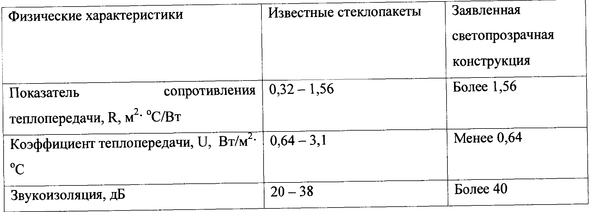
Таким образом, предлагаемое изобретение позволяет получить светопрозрачную конструкцию, имеющую повышенные теплоизоляционные показатели, обеспечивающую повышение защиты от холода и от избыточного проникновения солнечной радиации, создание эффекта солнечного коллектора в герметичной камере на основе принципа парника, снижение конвекции и возможность повышения изоляционных свойств за счет увеличения ширины герметичной камеры, повышенную защиту от торцевых ударов, повреждения (разбития) при перевозке, монтаже, благодаря рамке из термоизолирующего силового профиля, разборность конструкции для выполнения в процессе эксплуатации локального демонтажа без нарушения теплового контура здания до конструкции, состоящей из одного стеклопакета, включающего, по крайней мере, два стекла, в отличие от неразборных известных светопрозрачных конструкций в виде одинарного стекла или любых стеклопакетов, повышение герметичности, повышение звукоизоляции, отсутствие образования конденсата на стеклах, увеличение площади остекления без энергопотерь,
упрощение монтажа путем установки цельно изготовленной свегопрозрачной конструкции в проем без рамы, отсутствие промерзания откосов, повышение взломостойкости и пожаростойкости,
Что, в свою очередь, приводит к энергосбережению, к снижению эксплуатационных расходов на отопление и кондиционирование, снижению капитальных расходов за счет снижения лимита и стоимости подключения к теплоснабжению при централизованном отоплении и установки менее мощной системы отопления, отказа от системы кондиционирования, к повышению уровня пожаростойкости конструкции, снижению риска потери целостности, обрушения конструкции в результате пожара, к упрощению и обеспечению визуальной (без приборов) самодиагностики герметичности конструкции, которая исключает малейшее запотевание пространства между стеклами, к возможности изготовления открывающихся оконных створок, дверных полотен больших размеров, к снижению расходов на искусственное освещение, к отсутствию необходимости чистки внутреннего пространства в период эксплуатации, к снижению применения электрообогрева свегопрозрачных крыш, зимних садов, куполов, атриумов, зенитных фонарей и тому подобных конструкций, к возможности строительства полностью свегопрозрачных зданий без энергопотерь, к улучшению комфортного пребывания в помещении, к неограниченным возможностям в области архитектуры и дизайна.
Изобретение было раскрыто выше со ссылкой на конкретный вариант его осуществления. Для специалистов могут быть очевидны и иные варианты осуществления изобретения, не меняющие его сущности, как она раскрыта в настоящем описании. Соответственно, изобретение следует считать ограниченным по объему только нижеследующей формулой изобретения.
Claims
1. Свегопрозрачная конструкция, содержащая, по крайней мере, четыре стекла, объединенных, по крайней мере, в два независимых стеклопакета, содержащих каждый, по крайней мере, по два стекла, расположенных параллельно друг другу на расстоянии шириной 10-1000 мм, причем стекла в стекло пакетах склеены при помощи дистанционной рамки и герметика, а сами стеклопакеты соединены между собой при помощи рамки в виде термоизолирующего силового профиля, с образованием между внутренними стеклами стеклопакетов герметичной камеры.
2. Конструкция по п. 1, отличающаяся тем, что герметичная камера заполнена воздухом, инертным газом, углекислым газом или частично откаченным воздухом.
3. Конструкция по п. 2, отличающаяся тем, что в качестве инертного газа применены аргон, ксенон, криптон, гексафторид серы
4. Конструкция по п. 1, отличающаяся тем, что герметичная камера выполнена шириной 10-1000 мм
5. Конструкция по п. 1, отличающаяся тем, что пространство между стеклами в стеклопакете заполнено воздухом, инертным газом, углекислым газом.
Priority Applications (3)
| Application Number | Priority Date | Filing Date | Title |
|---|---|---|---|
| EA201700601A EA034269B1 (ru) | 2016-03-30 | 2016-04-05 | Энергоэффективная светопрозрачная конструкция |
| US16/088,839 US10662700B2 (en) | 2016-03-30 | 2016-04-05 | Energy efficient translucent structure |
| EP16897236.2A EP3438396A4 (en) | 2016-03-30 | 2016-04-05 | INDICATIVE ENERGY EFFICIENT STRUCTURE |
Applications Claiming Priority (2)
| Application Number | Priority Date | Filing Date | Title |
|---|---|---|---|
| RU2016111963 | 2016-03-30 | ||
| RU2016111963A RU2620241C1 (ru) | 2016-03-30 | 2016-03-30 | Энергоэффективная светопрозрачная конструкция |
Publications (1)
| Publication Number | Publication Date |
|---|---|
| WO2017171578A1 true WO2017171578A1 (ru) | 2017-10-05 |
Family
ID=58882568
Family Applications (1)
| Application Number | Title | Priority Date | Filing Date |
|---|---|---|---|
| PCT/RU2016/000190 Ceased WO2017171578A1 (ru) | 2016-03-30 | 2016-04-05 | Энергоэффективная светопрозрачная конструкция |
Country Status (5)
| Country | Link |
|---|---|
| US (1) | US10662700B2 (ru) |
| EP (1) | EP3438396A4 (ru) |
| EA (1) | EA034269B1 (ru) |
| RU (1) | RU2620241C1 (ru) |
| WO (1) | WO2017171578A1 (ru) |
Cited By (2)
| Publication number | Priority date | Publication date | Assignee | Title |
|---|---|---|---|---|
| WO2019161357A1 (en) | 2018-02-19 | 2019-08-22 | Kattmann Elias, LLC | Dynamic multi-pane insulating assembly and system |
| US12138887B2 (en) | 2018-02-19 | 2024-11-12 | Kattmann Elias, LLC | Dynamic multi-pane insulating assembly and system |
Families Citing this family (3)
| Publication number | Priority date | Publication date | Assignee | Title |
|---|---|---|---|---|
| RU2695045C1 (ru) * | 2019-01-07 | 2019-07-18 | Сергей Анатольевич Давыденко | Автомобильное стекло с изменяющейся прозрачностью |
| CN111980549B (zh) * | 2020-09-27 | 2024-10-25 | 蒋秉钧 | 一种两玻三腔复合轻体中空玻璃及其制造方法 |
| CN118517212A (zh) * | 2024-04-29 | 2024-08-20 | 信义节能玻璃(江门)有限公司 | 一种具有自发电加热除霜除雾除雪功能的节能中空玻璃 |
Citations (4)
| Publication number | Priority date | Publication date | Assignee | Title |
|---|---|---|---|---|
| US4081934A (en) * | 1976-09-03 | 1978-04-04 | Ppg Industries, Inc. | Seasonably adjustable window |
| SU1399441A1 (ru) * | 1986-07-31 | 1988-05-30 | Центральный научно-исследовательский и проектно-экспериментальный институт промышленных зданий и сооружений | Оконный блок |
| RU2476659C2 (ru) * | 2007-11-13 | 2013-02-27 | ИНФИНИТ ЭДЖ ТЕКНОЛОДЖИС, ЭлЭлСи | Оконная распорная деталь и оконный блок |
| RU146034U1 (ru) * | 2013-10-21 | 2014-09-27 | Владимир Юрьевич Овчаренко | Стеклопакет |
Family Cites Families (8)
| Publication number | Priority date | Publication date | Assignee | Title |
|---|---|---|---|---|
| US2834999A (en) * | 1955-11-17 | 1958-05-20 | Coldstream Refrigerator Mfg Lt | Sealed multiple glazed unit |
| US2918709A (en) * | 1956-04-30 | 1959-12-29 | Leonard J Corcoran | Transparent hot and cold insulating unit |
| US5009044A (en) * | 1987-06-25 | 1991-04-23 | Allied-Signal Inc. | Dual-pane thermal window with liquid crystal shade |
| FR2807783B1 (fr) | 2000-04-13 | 2002-12-20 | Saint Gobain Vitrage | Vitrage isolant et son procede de fabrication |
| EP1509668B1 (en) * | 2002-05-07 | 2006-11-08 | VKR Holding A/S | A panel element comprising a frame with a panel unit |
| US20070116907A1 (en) | 2005-11-18 | 2007-05-24 | Landon Shayne J | Insulated glass unit possessing room temperature-cured siloxane sealant composition of reduced gas permeability |
| RU2510704C2 (ru) | 2012-03-05 | 2014-04-10 | Александр Сергеевич Костюченко | Светопрозрачная конструкция с подогревом |
| EP2987936B1 (en) * | 2013-03-28 | 2018-10-10 | AGC-Lixil Window Technology Co., Ltd. | Multiplex glazed sash and product relating to multiplex glazed sash |
-
2016
- 2016-03-30 RU RU2016111963A patent/RU2620241C1/ru active
- 2016-04-05 US US16/088,839 patent/US10662700B2/en active Active
- 2016-04-05 EA EA201700601A patent/EA034269B1/ru not_active IP Right Cessation
- 2016-04-05 WO PCT/RU2016/000190 patent/WO2017171578A1/ru not_active Ceased
- 2016-04-05 EP EP16897236.2A patent/EP3438396A4/en not_active Withdrawn
Patent Citations (4)
| Publication number | Priority date | Publication date | Assignee | Title |
|---|---|---|---|---|
| US4081934A (en) * | 1976-09-03 | 1978-04-04 | Ppg Industries, Inc. | Seasonably adjustable window |
| SU1399441A1 (ru) * | 1986-07-31 | 1988-05-30 | Центральный научно-исследовательский и проектно-экспериментальный институт промышленных зданий и сооружений | Оконный блок |
| RU2476659C2 (ru) * | 2007-11-13 | 2013-02-27 | ИНФИНИТ ЭДЖ ТЕКНОЛОДЖИС, ЭлЭлСи | Оконная распорная деталь и оконный блок |
| RU146034U1 (ru) * | 2013-10-21 | 2014-09-27 | Владимир Юрьевич Овчаренко | Стеклопакет |
Non-Patent Citations (1)
| Title |
|---|
| See also references of EP3438396A4 * |
Cited By (6)
| Publication number | Priority date | Publication date | Assignee | Title |
|---|---|---|---|---|
| WO2019161357A1 (en) | 2018-02-19 | 2019-08-22 | Kattmann Elias, LLC | Dynamic multi-pane insulating assembly and system |
| EP3755935A4 (en) * | 2018-02-19 | 2021-10-20 | Kattmann Elias, LLC | DYNAMIC MULTI-PANEL INSULATION ARRANGEMENT AND SYSTEM |
| US11459815B2 (en) | 2018-02-19 | 2022-10-04 | Kattmann Elias, LLC | Dynamic multi-pane insulating assembly and system |
| US11802437B2 (en) | 2018-02-19 | 2023-10-31 | Kattmann Elias, LLC | Dynamic multi-pane insulating assembly and system |
| US12138887B2 (en) | 2018-02-19 | 2024-11-12 | Kattmann Elias, LLC | Dynamic multi-pane insulating assembly and system |
| US12480356B2 (en) | 2018-02-19 | 2025-11-25 | Kattmann Elias, LLC | Dynamic multi-pane insulating assembly and system |
Also Published As
| Publication number | Publication date |
|---|---|
| RU2620241C1 (ru) | 2017-05-23 |
| EA034269B1 (ru) | 2020-01-23 |
| US20190106932A1 (en) | 2019-04-11 |
| EP3438396A4 (en) | 2019-08-28 |
| EP3438396A1 (en) | 2019-02-06 |
| US10662700B2 (en) | 2020-05-26 |
| EA201700601A1 (ru) | 2018-04-30 |
Similar Documents
| Publication | Publication Date | Title |
|---|---|---|
| US8595994B1 (en) | Insulating glass unit with asymmetrical between-pane spaces | |
| EP3911827B1 (en) | Frame solution comprising compressed suspension elements | |
| US10267084B2 (en) | Panelized shadow box | |
| US6401428B1 (en) | Fenestration sealed frame, insulating glazing panels | |
| DK3198101T3 (en) | Spacer for double glazing | |
| KR101482298B1 (ko) | 알루미늄과 피브이씨를 적용한 복합 미서기 이중창 시스템 창호 | |
| US9661940B2 (en) | Glass element for a cabinet having a refrigerated chamber | |
| CN104781492B (zh) | 用于在设计成容纳较厚ig窗单元的窗框架中安装真空绝缘玻璃(vig)窗单元的隔离片系统 | |
| RU2620241C1 (ru) | Энергоэффективная светопрозрачная конструкция | |
| USH975H (en) | Thermal insulated glazing unit | |
| US20120324806A1 (en) | High R-Value, Removable and Transparent Window Insulation Panels | |
| EP2882920B1 (en) | Energy efficient fenestration assembly | |
| EP2188462A1 (en) | A pane module for use in a window | |
| EP3201414B1 (en) | Openable frameless door or window casement arrangement with insulated glazing | |
| KR20220123099A (ko) | 접착력이 향상된 스페이서(spacer) | |
| WO2012008871A1 (ru) | Стальная каркасно-рамная несущая конструкция стеклопакета | |
| EP3060739B1 (en) | Openable frameless door or window casement arrangement with insulated glazing | |
| RU2213193C2 (ru) | Стеклоблок для проемов помещений | |
| RU187580U1 (ru) | Ограждающая конструкция здания | |
| RU216306U1 (ru) | Самонесущий стеклопакет | |
| RU215808U1 (ru) | Самонесущий стеклопакет | |
| CN220203746U (zh) | 一种超低能耗建筑用门窗 | |
| RU207430U1 (ru) | Многослойное стекло | |
| CN218234875U (zh) | 太阳能得热系数和透光率可调的节能玻璃 | |
| RU159406U1 (ru) | Стеклопакет и дистанционная рамка |
Legal Events
| Date | Code | Title | Description |
|---|---|---|---|
| WWE | Wipo information: entry into national phase |
Ref document number: 201700601 Country of ref document: EA |
|
| NENP | Non-entry into the national phase |
Ref country code: DE |
|
| 121 | Ep: the epo has been informed by wipo that ep was designated in this application |
Ref document number: 16897236 Country of ref document: EP Kind code of ref document: A1 |