WO2017175439A1 - レール破断検知装置 - Google Patents
レール破断検知装置 Download PDFInfo
- Publication number
- WO2017175439A1 WO2017175439A1 PCT/JP2017/001131 JP2017001131W WO2017175439A1 WO 2017175439 A1 WO2017175439 A1 WO 2017175439A1 JP 2017001131 W JP2017001131 W JP 2017001131W WO 2017175439 A1 WO2017175439 A1 WO 2017175439A1
- Authority
- WO
- WIPO (PCT)
- Prior art keywords
- unit
- rail
- train
- track circuit
- current
- Prior art date
- Legal status (The legal status is an assumption and is not a legal conclusion. Google has not performed a legal analysis and makes no representation as to the accuracy of the status listed.)
- Ceased
Links
Images


Classifications
-
- B—PERFORMING OPERATIONS; TRANSPORTING
- B61—RAILWAYS
- B61L—GUIDING RAILWAY TRAFFIC; ENSURING THE SAFETY OF RAILWAY TRAFFIC
- B61L23/00—Control, warning or like safety means along the route or between vehicles or trains
- B61L23/04—Control, warning or like safety means along the route or between vehicles or trains for monitoring the mechanical state of the route
- B61L23/042—Track changes detection
- B61L23/044—Broken rails
-
- B—PERFORMING OPERATIONS; TRANSPORTING
- B61—RAILWAYS
- B61L—GUIDING RAILWAY TRAFFIC; ENSURING THE SAFETY OF RAILWAY TRAFFIC
- B61L1/00—Devices along the route controlled by interaction with the vehicle or train
- B61L1/18—Railway track circuits
- B61L1/181—Details
-
- B—PERFORMING OPERATIONS; TRANSPORTING
- B61—RAILWAYS
- B61L—GUIDING RAILWAY TRAFFIC; ENSURING THE SAFETY OF RAILWAY TRAFFIC
- B61L23/00—Control, warning or like safety means along the route or between vehicles or trains
- B61L23/04—Control, warning or like safety means along the route or between vehicles or trains for monitoring the mechanical state of the route
-
- E—FIXED CONSTRUCTIONS
- E01—CONSTRUCTION OF ROADS, RAILWAYS, OR BRIDGES
- E01B—PERMANENT WAY; PERMANENT-WAY TOOLS; MACHINES FOR MAKING RAILWAYS OF ALL KINDS
- E01B35/00—Applications of measuring apparatus or devices for track-building purposes
-
- G—PHYSICS
- G01—MEASURING; TESTING
- G01R—MEASURING ELECTRIC VARIABLES; MEASURING MAGNETIC VARIABLES
- G01R31/00—Arrangements for testing electric properties; Arrangements for locating electric faults; Arrangements for electrical testing characterised by what is being tested not provided for elsewhere
- G01R31/50—Testing of electric apparatus, lines, cables or components for short-circuits, continuity, leakage current or incorrect line connections
-
- B—PERFORMING OPERATIONS; TRANSPORTING
- B61—RAILWAYS
- B61L—GUIDING RAILWAY TRAFFIC; ENSURING THE SAFETY OF RAILWAY TRAFFIC
- B61L1/00—Devices along the route controlled by interaction with the vehicle or train
- B61L1/18—Railway track circuits
- B61L1/181—Details
- B61L1/185—Use of direct current
-
- B—PERFORMING OPERATIONS; TRANSPORTING
- B61—RAILWAYS
- B61L—GUIDING RAILWAY TRAFFIC; ENSURING THE SAFETY OF RAILWAY TRAFFIC
- B61L1/00—Devices along the route controlled by interaction with the vehicle or train
- B61L1/18—Railway track circuits
- B61L1/181—Details
- B61L1/187—Use of alternating current
-
- B—PERFORMING OPERATIONS; TRANSPORTING
- B61—RAILWAYS
- B61L—GUIDING RAILWAY TRAFFIC; ENSURING THE SAFETY OF RAILWAY TRAFFIC
- B61L25/00—Recording or indicating positions or identities of vehicles or trains or setting of track apparatus
- B61L25/02—Indicating or recording positions or identities of vehicles or trains
- B61L25/025—Absolute localisation, e.g. providing geodetic coordinates
-
- B—PERFORMING OPERATIONS; TRANSPORTING
- B61—RAILWAYS
- B61L—GUIDING RAILWAY TRAFFIC; ENSURING THE SAFETY OF RAILWAY TRAFFIC
- B61L25/00—Recording or indicating positions or identities of vehicles or trains or setting of track apparatus
- B61L25/02—Indicating or recording positions or identities of vehicles or trains
- B61L25/026—Relative localisation, e.g. using odometer
-
- B—PERFORMING OPERATIONS; TRANSPORTING
- B61—RAILWAYS
- B61L—GUIDING RAILWAY TRAFFIC; ENSURING THE SAFETY OF RAILWAY TRAFFIC
- B61L3/00—Devices along the route for controlling devices on the vehicle or train, e.g. to release brake or to operate a warning signal
- B61L3/16—Continuous control along the route
- B61L3/22—Continuous control along the route using magnetic or electrostatic induction; using electromagnetic radiation
- B61L3/221—Continuous control along the route using magnetic or electrostatic induction; using electromagnetic radiation using track circuits
Definitions
- the present invention relates to a rail breakage detecting device applicable to a rail provided with a track circuit.
- Patent Document 1 which is a conventional technique discloses a technique capable of distinguishing between a rail fracture state and a train existing line state using train position information.
- This invention is made in view of the above, Comprising: It aims at obtaining the rail breakage detection apparatus which can detect the rail breakage in a track circuit, without using the positional information on a train.
- the present invention uses information on whether the relay of the track circuit is on the saddle or is dropped, and information on the value of the current flowing in the track circuit.
- the rail breakage in the section in which the track circuit is provided is detected by determining whether or not the rail is broken and determining the presence of the train.
- FIG. 1 The figure which shows an example of a structure of the rail fracture
- FIG. The figure which shows an example of schematic structure when the train exists in the area of the track circuit shown in FIG.
- the flowchart which shows an example of operation
- FIG. The figure which shows an example of a structure of the rail fracture detection apparatus concerning Embodiment 2.
- FIG. The figure which shows an example of a structure of the rail fracture detection apparatus concerning Embodiment 3.
- FIG. The flowchart which shows an example of operation
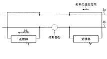
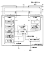
- FIG. 1 is a diagram illustrating an example of a configuration of a rail breakage detection apparatus according to a first exemplary embodiment of the present invention.
- a rail breakage detection device 5 shown in FIG. 1 includes a transmission unit 1, a reception unit 2, rails 3 a and 3 b to which the transmission unit 1 and the reception unit 2 are electrically connected, and a rail breakage detection unit 4.
- one section of the track circuit is shown in FIG. 1, and the traveling direction of the train is a direction from the reception unit 2 to the transmission unit 1.
- the transmission unit 1 includes a transmission unit power supply 11, a transmission unit resistor 12, a transmission unit current measurement unit 13, and a transmission unit power consumption calculation unit 14.
- the transmitter power supply 11 is a DC power supply connected in series between the rail 3a and the rail 3b.
- the transmitter resistor 12 is a resistor connected in series to the transmitter power supply 11.
- the transmitter current measuring unit 13 measures the current flowing through the transmitter resistor 12 and outputs a current measurement value I.
- the current measurement value I is input to the rail breakage detection unit 4.
- the transmission unit power consumption calculation unit 14 measures the power consumption in the transmission unit 1 and outputs a power consumption measurement value P.
- the power consumption measurement value P is calculated by the product of the voltage of the transmission unit power supply 11 and the current measurement value I measured by the transmission unit current measurement unit 13.
- the receiving unit 2 includes a relay 21 and a receiving unit voltage measuring unit 22.
- the receiver voltage measurement unit 22 measures the voltage applied to the relay 21 and outputs a voltage measurement value V.
- V the voltage applied to the relay 21
- the relay 21 falls, and when the applied voltage is equal to or higher than the preset threshold value, the relay 21 of the track circuit is I will go up.
- the relay falls and the train cannot enter the section of the track circuit.
- One end of the transmitter 1 and one end of the receiver 2 are connected to the rail 3a, and the other end of the transmitter 1 and the other end of the receiver 2 are connected to the rail 3b.
- the rail breakage detection unit 4 includes a determination unit 41.
- the determination unit 41 receives the current measurement value I from the transmission unit current measurement unit 13, the voltage measurement value V from the reception unit voltage measurement unit 22, and the power consumption measurement value P.
- FIG. 2 is a diagram illustrating an example of a schematic configuration when a train is on the track circuit section illustrated in FIG. 1.
- the train that is present is not shown, and the axle 6 of the train that is present is shown.
- the axle 6 short-circuits the rail 3a and the rail 3b. Therefore, in FIG. 2, the current from the transmitter 1 passes through the rail 3 a and flows to the rail 3 b through the axle 6. That is, the current is short-circuited by the axle 6.
- the current measurement values I of the transmitter current measurement unit 13 at this time is I 2.
- FIG. 3 is a diagram illustrating an example of a schematic configuration when rail breakage occurs in the section of the track circuit illustrated in FIG. 1.
- FIG. 3 there is a broken portion in the rail 3b.
- the current path is interrupted, and only a weak current flows.
- the current measurement value I of the transmitter current measurement unit 13 at this time is I 3 .
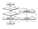
- FIG. 4 is a flowchart showing an example of the operation of the determination unit 41 of the rail breakage detection unit 4 shown in FIG.
- the determination unit 41 determines whether or not the relay of the track circuit in the section to be determined is on the saddle (S11).
- the voltage measurement value V of the receiver voltage measurement unit 22 is used to determine whether or not the relay of the track circuit is on the saddle. If the voltage measurement value V is greater than or equal to the preset threshold value, the track circuit relay is hoisting, and if the voltage measurement value V is less than the preset threshold value, the track circuit relay is falling. .
- the train is determined that the rail (S15). In other words, the relay is fall, and when the current value I is greater than I 3, the determination unit 41 determines that a train in the track circuit is rail. Or a voltage less than the threshold voltage measured value V is set in advance, and when the current value I is greater than I 3, the determination unit 41 determines that a train in the track circuit is rail.
- the determination unit 41 is a current value I of the transmitter current measurement unit 13 is determined whether or not greater than I 3
- the determination threshold I 0 may be set in advance, and the determination unit 41 may determine whether or not the current value I of the transmission unit current measurement unit 13 is greater than I 0 .
- the determination unit 41 can determine whether or not there is a rail break in the section of the track circuit.
- the determination unit 41 determines that a rail break exists, the train is stopped or the train is slowed down.
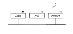
- the rail breakage detection unit 4 includes at least a processor, a memory, and an input unit, and the operation of each device can be realized by software.
- FIG. 5 is a diagram illustrating an example of a general configuration of hardware that realizes the rail breakage detection unit 4 according to the first embodiment.
- the apparatus shown in FIG. 5 includes a processor 42, a memory 43, and an input unit 44.
- the processor 42 performs calculation and control by software using the received data.
- the memory 43 stores received data or data and software necessary for the processor 42 to perform calculation and control.
- the input unit 44 receives the current measurement value I from the transmission unit current measurement unit 13 and the voltage measurement value V from the reception unit voltage measurement unit 22 as inputs.
- a plurality of processors 42 and memories 43 may be provided.
- the rail breakage detection apparatus uses information on whether the relay of the track circuit is on the saddle or is dropped, and information on the value of the current flowing in the track circuit.
- the rail breakage in the section where the track circuit is provided is detected.
- the rail breakage detection apparatus is provided between the two rails 3 a and 3 b, and includes a receiving unit 2 having a relay 21 of a track circuit, and a train traveling more than the receiving unit 2.
- the reception unit 2 includes a reception unit voltage measurement unit 22 that measures the voltage applied to the relay 21, and the transmission unit 1
- a transmitter unit power supply 11 that generates current
- a transmitter unit resistor 12 connected in series to the transmitter unit power source 11
- a transmitter unit current measuring unit 13 that measures the current of the transmitter unit resistor 12.
- the train position information is referred to and whether the train is in the track line or not depending on whether or not the train position information is included in the track circuit. It is possible to determine whether or not a broken portion is generated on the rail.
- the position information of the train which is on-vehicle information, and both the on-vehicle information and the ground information are required, so that the system is complicated.
- the position information of the train detected on the vehicle is not accurate because it is affected by the slipping or sliding of the wheels of the train.
- rail breakage in the track circuit can be detected using the voltage value of the receiving unit of the track circuit and the current value of the transmitting unit. Therefore, the rail breakage in the track circuit can be detected only by the information on the ground side without referring to the train position information that is on-vehicle information. Therefore, it is possible to detect a rail break in the track circuit without cooperation between the ground device and the on-vehicle device.
- the first embodiment can be realized with a simple configuration, it can be introduced at a low cost.
- the determination unit 41 detects the rail breakage using both the current measurement value I from the transmission unit current measurement unit 13 and the voltage measurement value V from the reception unit voltage measurement unit 22.
- rail breakage is detected using the current of the transmission unit 1 and the voltage of the reception unit 2, but the transmission unit uses the transmission unit power consumption calculation unit 14 provided on the transmission unit 1 side. Rail breakage may be detected by calculating power consumption on one side.
- a DC track circuit is described as an example of the track circuit.
- the track circuit may be an AC track circuit.
- the track circuit is illustrated and described in the first embodiment, the present invention is not limited to this and may be an electric circuit.
- this Embodiment 1 it is preferable to apply this Embodiment 1 to the area containing the curve part on a route. This is because the rail breakage is likely to occur in the curved portion on the route due to friction with the wheel. It is particularly preferable to apply the first embodiment to a portion where the radius of curvature of the curved portion on the route is small.
- Embodiment 1 it is also preferable to apply this Embodiment 1 to the area containing the welding part on a route. This is because rail breakage tends to occur at the welded portion on the route.
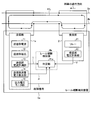
- FIG. FIG. 6 is a diagram illustrating an example of a configuration of the rail breakage detection apparatus according to the second exemplary embodiment of the present invention.
- a rail breakage detection device 5a shown in FIG. 6 includes a transmission unit 1a instead of the transmission unit 1, and a rail breakage detection unit 4a instead of the rail breakage detection unit 4 is different from the rail breakage detection device 5 shown in FIG. Different.
- Embodiment 1 is referred to for points not particularly mentioned.
- the transmission unit 1a has a configuration in which an output voltage monitoring unit 15 is added to the transmission unit 1 shown in FIG.
- the output voltage monitor unit 15 monitors the output voltage of the transmission unit power supply 11 and outputs a failure signal when the output voltage falls outside a preset voltage value range.
- the rail breakage detection unit 4a is different from the rail breakage detection unit 4 shown in FIG. 1 in that it includes a determination unit 41a to which this failure signal is input.
- FIG. 7 is a flowchart showing an example of the operation of the determination unit 41a of the rail breakage detection unit 4a shown in FIG.
- the process is started, and the determination unit 41a determines whether or not a failure signal has been received (S20).
- the determination unit 41a receives a failure signal (S20: Yes)
- the determination unit 41a has not received a failure signal (S20: No)
- the failure of the transmitter power supply 11 can be detected in advance by monitoring the output voltage of the transmitter power supply 11.
- FIG. FIG. 8 is a diagram illustrating an example of the configuration of the rail breakage detection apparatus according to the third embodiment of the present invention.
- a rail breakage detection device 5b shown in FIG. 8 is different from the rail breakage detection device 5a shown in FIG. 6 in that a rail breakage detection unit 4b is provided instead of the rail breakage detection unit 4a and a train position detection unit 7 is further provided.
- Embodiments 1 and 2 are used for points not particularly mentioned.
- the train position detection unit 7 outputs the train position information of the trains on the track having the rails 3a and 3b.
- This train position information is acquired from the pulse signal from the speed generator mounted on the train wheel and the absolute position information from the ground element, which the on-board device mounted on the train on the track has. This is car position information.
- the rail breakage detection unit 4b includes a determination unit 41b.
- the determination unit 41b includes a current measurement value I from the transmission unit current measurement unit 13, a voltage measurement value V from the reception unit voltage measurement unit 22, a power consumption measurement value P from the transmission unit power consumption calculation unit 14, and Train position information from the train position detector 7 is input.
- FIG. 9 is a flowchart showing an example of the operation of the determination unit 41b of the rail breakage detection unit 4b shown in FIG.
- the flowchart shown in FIG. 9 is different from the flowchart shown in FIG. 7 in the second embodiment in that the broken portion is specified (S31) when it is determined that there is a break in the track circuit section (S14). It is the same.
- FIG. 10 is a diagram showing an example of a schematic configuration when rail breakage occurs in the section of the track circuit shown in FIG.
- FIG. 10 shows the axles 6a and 6b of the train that is on the track, and the rail 3b has a broken portion.
- the axles 6a and 6b short-circuit the rail 3a and the rail 3b, and the traveling direction of the train is a direction from the axle 6a to the axle 6b.
- the position of the axle 6a is on the near side in the traveling direction from the broken portion, that is, the receiving portion 2 side, and the position of the axle 6b is on the front side in the traveling direction from the broken portion, that is, on the transmitting portion 1a side.
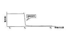
- FIG. 11 is a diagram illustrating an example of a relationship of current values according to the position of the axle, where the horizontal axis is the axle position and the vertical axis is the current value.
- the determination unit 41b of the rail break detection unit 4b shown in FIG. 8 refers to the train position information from the train position detection unit 7 and specifies that the position of the train axle when the current measurement value I rises is the break point. To do.
- the rail breakage detection apparatus includes the train position detection unit that acquires position information from the train on the track circuit and outputs the train position information, and the determination unit includes the train position information. And a rail fracture part is specified based on a current value or a current measurement value.
- the determination unit specifies that the position of the train axle when the current measurement value I rises is a broken portion.
- the rail breakage detection apparatus may include the transmission unit 1 instead of the transmission unit 1a.
Landscapes
- Engineering & Computer Science (AREA)
- Mechanical Engineering (AREA)
- Automation & Control Theory (AREA)
- Architecture (AREA)
- Civil Engineering (AREA)
- Structural Engineering (AREA)
- Physics & Mathematics (AREA)
- General Physics & Mathematics (AREA)
- Train Traffic Observation, Control, And Security (AREA)
- Investigating Or Analyzing Materials By The Use Of Electric Means (AREA)
- Geophysics And Detection Of Objects (AREA)
Abstract
Description
図1は、本発明の実施の形態1にかかるレール破断検知装置の構成の一例を示す図である。図1に示すレール破断検知装置5は、送信部1と、受信部2と、送信部1及び受信部2が電気的に接続されたレール3a,3bと、レール破断検知部4とを備える。ここで、図1には軌道回路の一区間が示されており、列車の進行方向は、受信部2から送信部1に向かう方向である。
図6は、本発明の実施の形態2にかかるレール破断検知装置の構成の一例を示す図である。図6に示すレール破断検知装置5aは、送信部1に代えて送信部1aを備え、レール破断検知部4に代えてレール破断検知部4aを備える点が図1に示すレール破断検知装置5と異なる。なお、特に言及しない点については実施の形態1を援用するものとする。
図8は、本発明の実施の形態3にかかるレール破断検知装置の構成の一例を示す図である。図8に示すレール破断検知装置5bは、レール破断検知部4aに代えてレール破断検知部4bを備え、更に列車位置検知部7を備える点が図6に示すレール破断検知装置5aと異なる。なお、特に言及しない点については実施の形態1,2を援用するものとする。
Claims (10)
- 軌道回路のリレーが扛上であるか又は落下であるかの情報と、該軌道回路に流れる電流値の情報とを用いて、レール破断の有無の判定及び列車の在線の判定を行うことで、該軌道回路が設けられた区間のレール破断を検知することを特徴とするレール破断検知装置。
- 前記リレーが落下であり、且つ前記電流値がしきい値より大きい場合には、前記軌道回路内に列車が在線していると判定することを特徴とする請求項1に記載のレール破断検知装置。
- 前記軌道回路のリレーを有する受信部よりも列車の進行方向側の2本のレール間に設けられて前記受信部と前記2本のレールとにより電流のループを形成する送信部を備え、
前記送信部が、送信部電源の電圧値と送信部抵抗に流れる電流値とにより消費電力を算出する消費電力算出部を備えることを特徴とする請求項1又は請求項2に記載のレール破断検知装置。 - 前記軌道回路上の列車から位置情報を取得して列車位置情報を出力する列車位置検知部を備え、
前記列車位置情報及び前記電流値に基づいてレール破断部分を特定することを特徴とする請求項1から請求項3のいずれか一項に記載のレール破断検知装置。 - 2本のレール間に設けられ、軌道回路のリレーを有する受信部と、
前記受信部よりも列車の進行方向側の前記2本のレール間に設けられて前記受信部と前記2本のレールとにより電流のループを形成する送信部と、
前記受信部からの情報と前記送信部からの情報とにより前記2本のレールの破断の有無及び列車の在線を判定する判定部とを備え、
前記受信部は、前記リレーへの印加電圧を計測する受信部電圧計測部を備え、
前記送信部は、前記電流を生じる送信部電源と、前記送信部電源に直列に接続された送信部抵抗と、前記送信部抵抗の電流を計測する送信部電流計測部とを備え、
前記判定部は、前記送信部電流計測部の電流計測値と前記受信部電圧計測部の電圧計測値とを用いて前記2本のレールの破断を判定することを特徴とするレール破断検知装置。 - 前記電圧計測値が予め設定した電圧しきい値未満であり、且つ前記電流計測値が電流しきい値より大きい場合には、前記軌道回路内に列車が在線していると判定することを特徴とする請求項5に記載のレール破断検知装置。
- 前記送信部が、前記送信部電源の電圧値と前記送信部抵抗に流れる電流値とにより消費電力を算出する消費電力算出部を備えることを特徴とする請求項5又は請求項6に記載のレール破断検知装置。
- 前記軌道回路上の列車から位置情報を取得して列車位置情報を出力する列車位置検知部を備え、
前記判定部は、前記列車位置情報及び前記電流計測値に基づいてレール破断部分を特定することを特徴とする請求項5から請求項7のいずれか一項に記載のレール破断検知装置。 - 前記軌道回路が、路線上の曲線部を含む区間に設けられていることを特徴とする請求項1から請求項8のいずれか一項に記載のレール破断検知装置。
- 前記軌道回路が、路線上の溶接部を含む区間に設けられていることを特徴とする請求項1から請求項8のいずれか一項に記載のレール破断検知装置。
Priority Applications (4)
| Application Number | Priority Date | Filing Date | Title |
|---|---|---|---|
| US16/077,227 US10946879B2 (en) | 2016-04-04 | 2017-01-13 | Rail fracture detection device |
| JP2018510233A JP6448853B2 (ja) | 2016-04-04 | 2017-01-13 | レール破断検知装置 |
| ES17778818T ES2945735T3 (es) | 2016-04-04 | 2017-01-13 | Dispositivo de detección de fractura de carril |
| EP17778818.9A EP3441279B1 (en) | 2016-04-04 | 2017-01-13 | Rail breakage detection device |
Applications Claiming Priority (2)
| Application Number | Priority Date | Filing Date | Title |
|---|---|---|---|
| PCT/JP2016/061037 WO2017175277A1 (ja) | 2016-04-04 | 2016-04-04 | レール破断検知装置 |
| JPPCT/JP2016/061037 | 2016-04-04 |
Publications (1)
| Publication Number | Publication Date |
|---|---|
| WO2017175439A1 true WO2017175439A1 (ja) | 2017-10-12 |
Family
ID=60000330
Family Applications (2)
| Application Number | Title | Priority Date | Filing Date |
|---|---|---|---|
| PCT/JP2016/061037 Ceased WO2017175277A1 (ja) | 2016-04-04 | 2016-04-04 | レール破断検知装置 |
| PCT/JP2017/001131 Ceased WO2017175439A1 (ja) | 2016-04-04 | 2017-01-13 | レール破断検知装置 |
Family Applications Before (1)
| Application Number | Title | Priority Date | Filing Date |
|---|---|---|---|
| PCT/JP2016/061037 Ceased WO2017175277A1 (ja) | 2016-04-04 | 2016-04-04 | レール破断検知装置 |
Country Status (5)
| Country | Link |
|---|---|
| US (1) | US10946879B2 (ja) |
| EP (1) | EP3441279B1 (ja) |
| JP (1) | JP6448853B2 (ja) |
| ES (1) | ES2945735T3 (ja) |
| WO (2) | WO2017175277A1 (ja) |
Cited By (4)
| Publication number | Priority date | Publication date | Assignee | Title |
|---|---|---|---|---|
| CN108819986A (zh) * | 2018-05-31 | 2018-11-16 | 北京全路通信信号研究设计院集团有限公司 | 一种用于对轨道线路进行故障检测的系统及方法 |
| CN109849964A (zh) * | 2019-03-29 | 2019-06-07 | 山西润泽丰科技开发有限公司 | 一种钢轨接头夹板断裂在线监测装置及其监测方法 |
| JP2021037830A (ja) * | 2019-09-03 | 2021-03-11 | 東日本旅客鉄道株式会社 | レール破断検知装置 |
| JPWO2024024274A1 (ja) * | 2022-07-29 | 2024-02-01 |
Families Citing this family (5)
| Publication number | Priority date | Publication date | Assignee | Title |
|---|---|---|---|---|
| CN107914737B (zh) * | 2017-10-19 | 2021-02-09 | 北京全路通信信号研究设计院集团有限公司 | 断轨检测方法及装置 |
| CN107985344B (zh) * | 2017-10-19 | 2021-02-09 | 北京全路通信信号研究设计院集团有限公司 | 断轨检测方法及装置 |
| US11919550B2 (en) | 2018-07-26 | 2024-03-05 | Mitsubishi Electric Corporation | Rail breakage detection device and rail breakage result management system |
| CN112114275B (zh) * | 2020-09-14 | 2024-11-22 | 交控科技股份有限公司 | 轨道状态检测方法及系统 |
| JP7604266B2 (ja) | 2021-02-26 | 2024-12-23 | 大同信号株式会社 | レール破断検知装置 |
Citations (6)
| Publication number | Priority date | Publication date | Assignee | Title |
|---|---|---|---|---|
| JPH058727A (ja) * | 1991-07-03 | 1993-01-19 | East Japan Railway Co | 軌道回路における列車在線検知用監視装置 |
| JP2003011816A (ja) * | 2001-07-02 | 2003-01-15 | Hitachi Ltd | 軌道回路装置 |
| JP2011057005A (ja) * | 2009-09-08 | 2011-03-24 | Railway Technical Res Inst | レール破断検知方法及びレール破断検知システム |
| JP2013043618A (ja) * | 2011-08-26 | 2013-03-04 | East Japan Railway Co | レール破断検知システム及びレール破断検知装置 |
| US20130240679A1 (en) * | 2012-03-19 | 2013-09-19 | Ansaldo Sts Usa, Inc. | Method and sequential monitoring overlay system for track circuits |
| US20150158510A1 (en) * | 2013-12-05 | 2015-06-11 | General Electric Company | Wayside monitoring system and method |
Family Cites Families (9)
| Publication number | Priority date | Publication date | Assignee | Title |
|---|---|---|---|---|
| DE3738696C2 (de) * | 1987-11-14 | 1998-05-14 | Sel Alcatel Ag | Verfahren und Einrichtung zur Ortung eines Schienenbruches |
| JPH04133601A (ja) * | 1990-09-21 | 1992-05-07 | Toshiba Corp | 保安機能付自動運転制御装置 |
| US5417388A (en) * | 1993-07-15 | 1995-05-23 | Stillwell; William R. | Train detection circuit |
| US5680054A (en) | 1996-02-23 | 1997-10-21 | Chemin De Fer Qns&L | Broken rail position detection using ballast electrical property measurement |
| US6102340A (en) * | 1997-02-07 | 2000-08-15 | Ge-Harris Railway Electronics, Llc | Broken rail detection system and method |
| JP4226400B2 (ja) * | 2003-07-17 | 2009-02-18 | 本田技研工業株式会社 | リレー駆動回路 |
| EP1824720A4 (en) * | 2004-12-13 | 2010-09-15 | Bombardier Transp Gmbh | SYSTEM FOR DETECTING BROKEN RAILS |
| JP2012188009A (ja) | 2011-03-10 | 2012-10-04 | Railway Technical Research Institute | レール破断検知方法及びレール破断検知装置 |
| US9701326B2 (en) * | 2014-09-12 | 2017-07-11 | Westinghouse Air Brake Technologies Corporation | Broken rail detection system for railway systems |
-
2016
- 2016-04-04 WO PCT/JP2016/061037 patent/WO2017175277A1/ja not_active Ceased
-
2017
- 2017-01-13 WO PCT/JP2017/001131 patent/WO2017175439A1/ja not_active Ceased
- 2017-01-13 US US16/077,227 patent/US10946879B2/en not_active Expired - Fee Related
- 2017-01-13 EP EP17778818.9A patent/EP3441279B1/en active Active
- 2017-01-13 JP JP2018510233A patent/JP6448853B2/ja not_active Expired - Fee Related
- 2017-01-13 ES ES17778818T patent/ES2945735T3/es active Active
Patent Citations (6)
| Publication number | Priority date | Publication date | Assignee | Title |
|---|---|---|---|---|
| JPH058727A (ja) * | 1991-07-03 | 1993-01-19 | East Japan Railway Co | 軌道回路における列車在線検知用監視装置 |
| JP2003011816A (ja) * | 2001-07-02 | 2003-01-15 | Hitachi Ltd | 軌道回路装置 |
| JP2011057005A (ja) * | 2009-09-08 | 2011-03-24 | Railway Technical Res Inst | レール破断検知方法及びレール破断検知システム |
| JP2013043618A (ja) * | 2011-08-26 | 2013-03-04 | East Japan Railway Co | レール破断検知システム及びレール破断検知装置 |
| US20130240679A1 (en) * | 2012-03-19 | 2013-09-19 | Ansaldo Sts Usa, Inc. | Method and sequential monitoring overlay system for track circuits |
| US20150158510A1 (en) * | 2013-12-05 | 2015-06-11 | General Electric Company | Wayside monitoring system and method |
Non-Patent Citations (1)
| Title |
|---|
| See also references of EP3441279A4 * |
Cited By (7)
| Publication number | Priority date | Publication date | Assignee | Title |
|---|---|---|---|---|
| CN108819986A (zh) * | 2018-05-31 | 2018-11-16 | 北京全路通信信号研究设计院集团有限公司 | 一种用于对轨道线路进行故障检测的系统及方法 |
| CN109849964A (zh) * | 2019-03-29 | 2019-06-07 | 山西润泽丰科技开发有限公司 | 一种钢轨接头夹板断裂在线监测装置及其监测方法 |
| JP2021037830A (ja) * | 2019-09-03 | 2021-03-11 | 東日本旅客鉄道株式会社 | レール破断検知装置 |
| JP7303705B2 (ja) | 2019-09-03 | 2023-07-05 | 東日本旅客鉄道株式会社 | レール破断検知装置 |
| JPWO2024024274A1 (ja) * | 2022-07-29 | 2024-02-01 | ||
| WO2024024274A1 (ja) * | 2022-07-29 | 2024-02-01 | 株式会社日立製作所 | レール破断検知システム及びレール破断検知方法 |
| JP7776650B2 (ja) | 2022-07-29 | 2025-11-26 | 株式会社日立製作所 | レール破断検知システム及びレール破断検知方法 |
Also Published As
| Publication number | Publication date |
|---|---|
| EP3441279A1 (en) | 2019-02-13 |
| ES2945735T3 (es) | 2023-07-06 |
| JPWO2017175439A1 (ja) | 2018-11-01 |
| US10946879B2 (en) | 2021-03-16 |
| EP3441279A4 (en) | 2019-07-31 |
| US20190047600A1 (en) | 2019-02-14 |
| JP6448853B2 (ja) | 2019-01-09 |
| EP3441279B1 (en) | 2023-04-26 |
| WO2017175277A1 (ja) | 2017-10-12 |
Similar Documents
| Publication | Publication Date | Title |
|---|---|---|
| JP6448853B2 (ja) | レール破断検知装置 | |
| US10081379B2 (en) | Broken rail detection system for communications-based train control | |
| RU2419568C2 (ru) | Система и способ обнаружения излома рельса или транспортного средства | |
| US20070132463A1 (en) | System and method for detecting rail break/vehicle | |
| CN105431342B (zh) | 用于监控被引导车辆的正确复轨的方法和设备 | |
| US11325623B2 (en) | Rail breakage detection device and rail breakage detection system | |
| JP6535619B2 (ja) | 列車制御システム | |
| JP5939692B2 (ja) | 踏切障害物多重コンピューター視覚識別システム | |
| KR101749890B1 (ko) | 차륜 검지 시스템 | |
| KR20140143180A (ko) | 속도 검출 장치 | |
| US20110127388A1 (en) | Device for the detection of the occupied or free state of a track section | |
| KR101550239B1 (ko) | 단등형 3현시 led 신호기를 이용한 열차 제어 방법 및 장치 | |
| KR20160045263A (ko) | 타이어 수명 예측 장치 및 방법 | |
| NL2037490B1 (nl) | Veiligheidsinrichting voor het bewaken van de integriteit van een treinsamenstel | |
| JP2002053040A (ja) | 鉄道車両の走行異常判別システム | |
| KR101599924B1 (ko) | 등거리 측정 제어 장치 및 등거리 측정 제어 방법 | |
| KR102835410B1 (ko) | 주행용 고무차륜의 상태 모니터링 시스템 및 방법 | |
| JP4727686B2 (ja) | 短絡支援装置及び短絡支援方法 | |
| KR102108765B1 (ko) | 철도 레일의 이상여부 감지장치 | |
| JP7014945B2 (ja) | レール破断検知装置 | |
| HK1232499B (zh) | 监视车辆的行驶状态的方法和设备和具有这种设备的车辆 | |
| JP2016116263A (ja) | 電力変換装置及び電力変換装置の制御方法 |
Legal Events
| Date | Code | Title | Description |
|---|---|---|---|
| ENP | Entry into the national phase |
Ref document number: 2018510233 Country of ref document: JP Kind code of ref document: A |
|
| NENP | Non-entry into the national phase |
Ref country code: DE |
|
| WWE | Wipo information: entry into national phase |
Ref document number: 2017778818 Country of ref document: EP |
|
| ENP | Entry into the national phase |
Ref document number: 2017778818 Country of ref document: EP Effective date: 20181105 |
|
| 121 | Ep: the epo has been informed by wipo that ep was designated in this application |
Ref document number: 17778818 Country of ref document: EP Kind code of ref document: A1 |