WO2017175537A1 - インホイールモータ動力線の配線構造およびインホイールモータ駆動装置 - Google Patents
インホイールモータ動力線の配線構造およびインホイールモータ駆動装置 Download PDFInfo
- Publication number
- WO2017175537A1 WO2017175537A1 PCT/JP2017/009520 JP2017009520W WO2017175537A1 WO 2017175537 A1 WO2017175537 A1 WO 2017175537A1 JP 2017009520 W JP2017009520 W JP 2017009520W WO 2017175537 A1 WO2017175537 A1 WO 2017175537A1
- Authority
- WO
- WIPO (PCT)
- Prior art keywords
- power line
- wheel
- wheel motor
- motor drive
- drive device
- Prior art date
- Legal status (The legal status is an assumption and is not a legal conclusion. Google has not performed a legal analysis and makes no representation as to the accuracy of the status listed.)
- Ceased
Links
Images














Classifications
-
- B—PERFORMING OPERATIONS; TRANSPORTING
- B60—VEHICLES IN GENERAL
- B60K—ARRANGEMENT OR MOUNTING OF PROPULSION UNITS OR OF TRANSMISSIONS IN VEHICLES; ARRANGEMENT OR MOUNTING OF PLURAL DIVERSE PRIME-MOVERS IN VEHICLES; AUXILIARY DRIVES FOR VEHICLES; INSTRUMENTATION OR DASHBOARDS FOR VEHICLES; ARRANGEMENTS IN CONNECTION WITH COOLING, AIR INTAKE, GAS EXHAUST OR FUEL SUPPLY OF PROPULSION UNITS IN VEHICLES
- B60K1/00—Arrangement or mounting of electrical propulsion units
- B60K1/04—Arrangement or mounting of electrical propulsion units of the electric storage means for propulsion
-
- B—PERFORMING OPERATIONS; TRANSPORTING
- B60—VEHICLES IN GENERAL
- B60G—VEHICLE SUSPENSION ARRANGEMENTS
- B60G13/00—Resilient suspensions characterised by arrangement, location or type of vibration dampers
-
- B—PERFORMING OPERATIONS; TRANSPORTING
- B60—VEHICLES IN GENERAL
- B60G—VEHICLE SUSPENSION ARRANGEMENTS
- B60G7/00—Pivoted suspension arms; Accessories thereof
- B60G7/001—Suspension arms, e.g. constructional features
-
- B—PERFORMING OPERATIONS; TRANSPORTING
- B60—VEHICLES IN GENERAL
- B60K—ARRANGEMENT OR MOUNTING OF PROPULSION UNITS OR OF TRANSMISSIONS IN VEHICLES; ARRANGEMENT OR MOUNTING OF PLURAL DIVERSE PRIME-MOVERS IN VEHICLES; AUXILIARY DRIVES FOR VEHICLES; INSTRUMENTATION OR DASHBOARDS FOR VEHICLES; ARRANGEMENTS IN CONNECTION WITH COOLING, AIR INTAKE, GAS EXHAUST OR FUEL SUPPLY OF PROPULSION UNITS IN VEHICLES
- B60K7/00—Disposition of motor in, or adjacent to, traction wheel
- B60K7/0007—Disposition of motor in, or adjacent to, traction wheel the motor being electric
-
- B—PERFORMING OPERATIONS; TRANSPORTING
- B60—VEHICLES IN GENERAL
- B60R—VEHICLES, VEHICLE FITTINGS, OR VEHICLE PARTS, NOT OTHERWISE PROVIDED FOR
- B60R16/00—Electric or fluid circuits specially adapted for vehicles and not otherwise provided for; Arrangement of elements of electric or fluid circuits specially adapted for vehicles and not otherwise provided for
- B60R16/02—Electric or fluid circuits specially adapted for vehicles and not otherwise provided for; Arrangement of elements of electric or fluid circuits specially adapted for vehicles and not otherwise provided for electric constitutive elements
- B60R16/0207—Wire harnesses
-
- B—PERFORMING OPERATIONS; TRANSPORTING
- B62—LAND VEHICLES FOR TRAVELLING OTHERWISE THAN ON RAILS
- B62D—MOTOR VEHICLES; TRAILERS
- B62D9/00—Steering deflectable wheels not otherwise provided for
-
- B—PERFORMING OPERATIONS; TRANSPORTING
- B60—VEHICLES IN GENERAL
- B60K—ARRANGEMENT OR MOUNTING OF PROPULSION UNITS OR OF TRANSMISSIONS IN VEHICLES; ARRANGEMENT OR MOUNTING OF PLURAL DIVERSE PRIME-MOVERS IN VEHICLES; AUXILIARY DRIVES FOR VEHICLES; INSTRUMENTATION OR DASHBOARDS FOR VEHICLES; ARRANGEMENTS IN CONNECTION WITH COOLING, AIR INTAKE, GAS EXHAUST OR FUEL SUPPLY OF PROPULSION UNITS IN VEHICLES
- B60K17/00—Arrangement or mounting of transmissions in vehicles
- B60K17/04—Arrangement or mounting of transmissions in vehicles characterised by arrangement, location or kind of gearing
- B60K17/043—Transmission unit disposed in on near the vehicle wheel, or between the differential gear unit and the wheel
-
- B—PERFORMING OPERATIONS; TRANSPORTING
- B60—VEHICLES IN GENERAL
- B60K—ARRANGEMENT OR MOUNTING OF PROPULSION UNITS OR OF TRANSMISSIONS IN VEHICLES; ARRANGEMENT OR MOUNTING OF PLURAL DIVERSE PRIME-MOVERS IN VEHICLES; AUXILIARY DRIVES FOR VEHICLES; INSTRUMENTATION OR DASHBOARDS FOR VEHICLES; ARRANGEMENTS IN CONNECTION WITH COOLING, AIR INTAKE, GAS EXHAUST OR FUEL SUPPLY OF PROPULSION UNITS IN VEHICLES
- B60K7/00—Disposition of motor in, or adjacent to, traction wheel
- B60K2007/0038—Disposition of motor in, or adjacent to, traction wheel the motor moving together with the wheel axle
-
- B—PERFORMING OPERATIONS; TRANSPORTING
- B60—VEHICLES IN GENERAL
- B60K—ARRANGEMENT OR MOUNTING OF PROPULSION UNITS OR OF TRANSMISSIONS IN VEHICLES; ARRANGEMENT OR MOUNTING OF PLURAL DIVERSE PRIME-MOVERS IN VEHICLES; AUXILIARY DRIVES FOR VEHICLES; INSTRUMENTATION OR DASHBOARDS FOR VEHICLES; ARRANGEMENTS IN CONNECTION WITH COOLING, AIR INTAKE, GAS EXHAUST OR FUEL SUPPLY OF PROPULSION UNITS IN VEHICLES
- B60K7/00—Disposition of motor in, or adjacent to, traction wheel
- B60K2007/0061—Disposition of motor in, or adjacent to, traction wheel the motor axle being parallel to the wheel axle
-
- B—PERFORMING OPERATIONS; TRANSPORTING
- B60—VEHICLES IN GENERAL
- B60Y—INDEXING SCHEME RELATING TO ASPECTS CROSS-CUTTING VEHICLE TECHNOLOGY
- B60Y2410/00—Constructional features of vehicle sub-units
- B60Y2410/115—Electric wiring; Electric connectors
Definitions
- the present invention relates to a power line that extends from an in-wheel motor drive device to a vehicle body and supplies electric power from the vehicle body to the in-wheel motor drive device.
- an in-wheel motor is provided inside a wheel of an electric vehicle and the wheel is driven by the in-wheel motor.
- Such an electric vehicle is advantageous in that it is not necessary to mount an engine or a motor on the vehicle body, and the interior space of the vehicle body such as a living room space or a cargo space can be enlarged.
- An in-wheel motor is connected to the body of the electric vehicle via a suspension device.
- an in-wheel motor control unit, a battery, and an inverter are mounted on the vehicle body.
- an in-wheel motor connected to the unsprung portion (wheel side) of the suspension device and an inverter mounted on the sprung portion (vehicle body side) of the suspension device are connected by a power line.
- a power line for supplying electric power from an inverter to an in-wheel motor conventionally, for example, the one described in Japanese Patent No. 4511976 (Patent Document 1) is known.
- the in-wheel motor Due to the action of the suspension device, the in-wheel motor is displaced in the vertical direction with respect to the vehicle body or steered in the horizontal direction. For this reason, it is necessary to appropriately support the middle part of the power line so that the power line does not bend excessively.
- an intermediate portion of the power line is attached to the end surface of the in-wheel motor by a clamp member.
- a plurality of fins are provided upright on the surface of the in-wheel motor described in the patent document.
- the present inventor has found that there is a further improvement in the conventional wiring structure. That is, since the clamp member is attached to the surface of the in-wheel motor, fins cannot be provided at the attachment location. Therefore, a sufficient number of cooling fins cannot be provided in the in-wheel motor.
- an object of the present invention is to provide a wiring structure capable of supporting a middle portion of a power line without providing a clamp member on the surface of the in-wheel motor.
- the wiring structure of the in-wheel motor power line includes an in-wheel motor drive device for driving a wheel, an upper end portion and a lower end portion, the upper end portion being connected to the vehicle body side member, and the lower end portion being an in-wheel portion.
- a damper connected to the motor drive device; a power line extending from the in-wheel motor drive device to the vehicle body; and a clamp member provided at a lower end portion of the damper to hold a middle portion of the power line.
- the clamp member that holds the middle portion of the power line is disposed apart from the in-wheel motor drive device, a sufficient number of cooling fins are provided on the surface of the in-wheel motor drive device. be able to.
- the damper is included in a strut that extends in the vertical direction and can be expanded and contracted in the vertical direction, and attenuates the expansion and contraction of the strut.
- the in-wheel motor drive device may be connected to the vehicle body side member by a combination of a damper and a suspension arm.
- the in-wheel motor drive device can be steered around a turning axis that intersects with the upper end of the strut and extends in the vertical direction.
- the in-wheel motor drive device may drive a non-turning wheel that is not steered.
- the clamp member includes an elastic member surrounding the outer periphery of the power line.
- the bending which acts on a power line can be relieve
- an intermediate portion of the power line may be surrounded by an O-shaped or C-shaped metal member.
- the elastic member is a block having a plurality of through holes, and a power line is passed through each through hole.
- a plurality of power lines can be arranged in an orderly manner.
- a plurality of power lines may be passed through one through hole.
- a clamp member includes a pair of base members that sandwich a lower end of a damper, a pair of end wall portions facing each other in the horizontal direction, and a horizontal position from one end wall portion to the other end wall portion. And a pair of end wall portions attached to the base member and constraining to hold the side surfaces of the elastic member. According to this embodiment, the horizontal movement of the power line can be restricted.
- the clamp member is disposed so as to overlap the wheel rim of the wheel as viewed in the axle direction of the wheel. According to this embodiment, it can prevent that a power line bends and interferes with a wheel. As another embodiment, the clamp member may be arranged away from the wheel rim of the wheel as viewed in the axle direction of the wheel.
- the clamp member is disposed so as to overlap with the turning axis when viewed in the axle direction of the wheel. According to this embodiment, the bending of the power line when the in-wheel motor drive device steers can be reduced. As another embodiment, the clamp member is arranged so as to be shifted in the vehicle front-rear direction from the wheel rim of the wheel as viewed in the axle direction of the wheel.
- a damper lower end portion includes a shaft portion and a damper bracket having an in-wheel motor connecting portion that is attached and fixed to the shaft portion and extends downward from the shaft portion to be coupled to an in-wheel motor drive device.
- the clamp member is provided on the shaft portion.
- the clamp member may be provided on the damper bracket.
- the power line extends in the vertical direction and is connected to the in-wheel motor driving device side at the lower side and connected to the vehicle body side at the upper side, and is driven in the in-wheel motor at the upper side.
- the clamp member grips the first region and the second region, including a second region connected to the apparatus side and connected to the vehicle body side below.
- the power line can be wired so as to be folded along the lower end of the damper.
- an in-wheel motor drive device, a damper, a power line, and a clamp member are respectively disposed on both sides in the vehicle width direction of the vehicle body, and a stabilizer extending from one side to the other side in the vehicle width direction of the vehicle body, It further includes a pair of stabilizer links arranged on both sides of the vehicle body in the vehicle width direction, and the stabilizer link is connected to the end of the stabilizer at one end and to the clamp member at the other end.
- the number of parts for connecting the stabilizer link to the lower end of the damper can be reduced.
- the other end of the stabilizer link may be separated from the clamp member and connected to the lower end of the damper.
- the present invention can also be established as an in-wheel motor drive device including an in-wheel motor power line.
- the in-wheel motor drive device of the present invention includes a wheel hub coupled to a wheel, a motor rotating shaft that drives the wheel hub, a casing that forms an outer shell, and a motor unit that has a power line connection provided in the casing, and one end thereof.
- a power line connecting portion, the other end extending to a vehicle body outside the casing, and a bendable power line for supplying electric power from the vehicle body to the motor portion, and connected to a lower end portion of the damper among the dampers extending vertically To do.
- the middle part of a power line is hold
- the clamp member that holds the middle portion of the power line is provided not at the in-wheel motor drive device but at the lower end of the damper, a sufficient number of cooling fins on the surface of the in-wheel motor drive device. Can be provided.
- a sufficient number of cooling fins can be provided on the surface of the in-wheel motor drive device. Therefore, the cooling effect of the in-wheel motor drive device can be improved.
- FIG. 1 is a schematic diagram showing a wiring structure of an in-wheel motor power line as a reference example, and shows a state viewed from the inner side in the vehicle width direction.
- FIG. 2 is a schematic diagram showing a reference example, and shows a state viewed from the front of the vehicle.
- FIG. 3 is a schematic view showing a reference example, and shows a state seen from above.
- the wheel wheel W, the in-wheel motor drive device 10, and the suspension device 70 are disposed outside the vehicle body 101 (only the outer portion in the vehicle width direction of the vehicle body is shown in FIG. 2). Further, the wheel wheel W, the in-wheel motor drive device 10 and the suspension device 70 are arranged symmetrically on both sides of the vehicle body 101 in the vehicle width direction, and constitute an electric vehicle.
- a tire T indicated by a virtual line is fitted to the outer periphery of the wheel W.
- Wheel wheel W and tire T constitute a wheel.
- the rim portion Wr of the wheel wheel W defines an inner space area of the wheel.
- the in-wheel motor drive device 10 is disposed in the inner space area.
- the in-wheel motor drive device 10 is connected to the wheel wheel W to drive the wheel.
- the suspension device 70 is a strut suspension device, and includes a lower arm 71 extending in the vehicle width direction and a strut 76 disposed above the lower arm 71 and extending in the vertical direction.
- the strut 76 is disposed on the inner side in the vehicle width direction with respect to the wheel wheel W and the in-wheel motor driving device 10, the lower end of the strut 76 is coupled to the in-wheel motor driving device 10, and the upper end of the strut 76 is above the wheel wheel W.
- the strut 76, the upper part of the wheel W, and the upper part of the in-wheel motor drive device 10 are accommodated in a wheel house 102 formed on the outer side in the vehicle width direction of the vehicle body 101.
- the strut 76 is a suspension member that has a built-in shock absorber 77 in the upper end region and can be expanded and contracted in the vertical direction.
- a coil spring 78 which is schematically shown by phantom lines, is disposed on the outer periphery of the shock absorber 77 to relieve the vertical axial force acting on the strut 76.
- a pair of coil spring seats 79 b and 79 c that hold the upper end and the lower end of the coil spring 78 are provided at the upper end portion and the central portion of the strut 76.
- Inside the shock absorber 77 is provided a damper that attenuates the axial force acting on the strut 76.
- the lower arm 71 is a suspension member disposed below the axis O of the in-wheel motor drive device 10, and includes a vehicle width direction outer end 72 and vehicle width direction inner ends 73d and 73f.
- the lower arm 71 is connected to the in-wheel motor drive device 10 via the ball joint 60 at the outer end 72 in the vehicle width direction.
- the lower arm 71 is connected to a vehicle body side member (not shown) at the vehicle width direction inner ends 73d and 73f.
- the lower arm 71 can swing in the vertical direction with the vehicle width direction inner ends 73d and 73f as base ends and the vehicle width direction outer ends 72 as free ends.
- the vehicle body side member refers to a member that is attached to the vehicle body side as viewed from a member to be described.
- a straight line connecting the outer end 72 in the vehicle width direction and the upper end 76a of the strut 76 extends in the vertical direction to form a turning axis K.
- the turning axis K basically extends in the vertical direction, but may be slightly inclined in the vehicle width direction and / or the vehicle longitudinal direction. In the figure, when the vehicle width direction inner ends 73d and 73f are not distinguished, the reference numeral 73 is simply given.
- a tie rod 80 is disposed above the lower arm 71.
- the tie rod 80 extends in the vehicle width direction, and an outer end in the vehicle width direction of the tie rod 80 is rotatably connected to the in-wheel motor drive device 10.
- the inner end of the tie rod 80 in the vehicle width direction is connected to a steering device (not shown).
- the steering device moves the tie rod 80 forward and backward in the vehicle width direction to steer the in-wheel motor drive device 10 and the wheel wheel W about the turning axis K.
- FIG. 4 is a schematic view showing the in-wheel motor drive device shown in FIGS. 1 to 3 taken out and showing a state seen from the outside in the vehicle width direction.
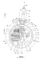
- FIG. 5 is a cross-sectional view showing the in-wheel motor drive device, and schematically shows a state seen from the outside in the vehicle width direction. In FIG. 5, each gear inside the speed reduction portion is represented by a tooth tip circle, and individual teeth are omitted.
- FIG. 6 is a developed sectional view schematically showing the in-wheel motor drive device. 6, the plane including the axis M and the axis Nf, the plane including the axis Nf and the axis Nl, and the plane including the axis Nl and the axis O illustrated in FIG. 5 are connected in this order. It is a development plane.
- FIG. 7 is a longitudinal sectional view showing the in-wheel motor drive device, which is shown together with the wheel and the suspension device. In order to avoid the complexity of the drawing, the gears inside the speed reduction portion are omitted
- the in-wheel motor drive device 10 includes a wheel hub bearing portion 11 connected to the center of the wheel wheel W represented by a virtual line, a motor portion 21 that drives the wheel wheel W of the wheel, and a motor portion. Is provided in a wheel house (not shown) of the electric vehicle.
- the motor unit 21 and the speed reduction unit 31 are not arranged coaxially with the axis O of the wheel hub bearing unit 11 but are arranged offset from the axis O of the wheel hub bearing unit 11 as shown in FIG.
- the in-wheel motor drive device 10 can drive an electric vehicle at a speed of 0 to 180 km / h on a public road.
- the wheel hub bearing portion 11 includes an outer ring 12 as a wheel hub coupled to the wheel wheel W, an inner fixing member 13 passed through a center hole of the outer ring 12, an outer ring 12 and an inner fixing member 13.
- a plurality of rolling elements 14 disposed in the annular gap are configured to constitute an axle.
- the inner fixing member 13 includes a non-rotating fixing shaft 15, a pair of inner races 16, a retaining nut 17, and a carrier 18.
- the fixed shaft 15 has a root portion 15r having a larger diameter than the tip portion 15e.
- the inner race 16 is fitted to the outer periphery of the fixed shaft 15 between the root portion 15r and the tip portion 15e.
- the retaining nut 17 is screwed into the tip portion 15e of the fixed shaft 15, and the inner race 16 is fixed between the retaining nut 17 and the root portion 15r.
- the fixed shaft 15 extends along the axis O and penetrates the main body casing 43 that forms the outline of the speed reduction portion 31.
- the tip 15e of the fixed shaft 15 passes through an opening 43p formed in the front portion 43f of the main body casing 43, and protrudes outward in the vehicle width direction from the front portion 43f.
- the root portion 15r of the fixed shaft 15 passes through an opening 43q formed in the back surface portion 43b from the inner side in the vehicle width direction than the back surface portion 43b of the main body casing 43.
- the front portion 43f and the back portion 43b are wall portions facing each other with an interval in the direction of the axis O.
- a carrier 18 is attached and fixed to the root portion 15r.
- the carrier 18 is connected to the suspension device 70 and the tie rod 80 outside the main body casing 43.
- the rolling elements 14 are arranged in double rows with a separation in the direction of the axis O.
- the outer peripheral surface of one inner race 16 in the axis O direction constitutes the inner raceway surface of the rolling elements 14 in the first row, and faces one inner peripheral surface of the outer ring 12 in the axis O direction.
- the outer peripheral surface of the other inner race 16 in the direction of the axis O constitutes the inner raceway surface of the rolling elements 14 in the second row, and faces the other inner peripheral surface of the outer ring 12 in the direction of the axis O.
- the vehicle width direction outer side (outboard side) is also referred to as one axial direction
- the vehicle width direction inner side (inboard side) is also referred to as the other axial direction. 6 corresponds to the vehicle width direction.
- the inner peripheral surface of the outer ring 12 constitutes the outer raceway surface of the rolling element 14.
- a flange portion 12f is formed at one end of the outer ring 12 in the axis O direction.
- the flange portion 12f constitutes a coupling seat portion for coupling coaxially with the brake disc BD and the spoke portion Ws of the wheel / wheel W.
- the outer ring 12 is coupled to the brake disc BD and the wheel wheel W at the flange portion 12f, and rotates integrally with the wheel wheel W.
- the flange portion 12f may be a protruding portion that protrudes toward the outer diameter side with an interval in the circumferential direction.
- the motor unit 21 includes a motor rotating shaft 22, a rotor 23, a stator 24, a motor casing 25, and a motor casing cover 25 v, and is sequentially arranged from the axis M of the motor unit 21 to the outer diameter side in this order. Is done.
- the motor unit 21 is a radial gap motor of an inner rotor and outer stator type, but may be of other types.
- the motor unit 21 may be an axial gap motor.
- the axis M that is the rotation center of the motor rotation shaft 22 and the rotor 23 extends in parallel with the axis O of the wheel hub bearing portion 11. That is, the motor unit 21 is disposed offset from the axis O of the wheel hub bearing unit 11. Most of the axial positions of the motor unit 21 excluding the tip of the motor rotating shaft 22 do not overlap with the axial positions of the inner fixing member 13 as shown in FIG.
- the motor casing 25 has a cylindrical shape, is coupled to the back portion 43b of the main body casing 43 at one end in the axis M direction, and is sealed by a lid-like motor casing cover 25v at the other end in the axis M direction. Both ends of the motor rotating shaft 22 are rotatably supported by the motor casing 25 and the motor casing cover 25v via rolling bearings 27 and 28.
- the motor unit 21 drives the outer ring 12 and the wheels.
- a power line terminal box 25 b is provided on the upper part of the in-wheel motor drive device 10.
- the power line terminal box 25b is formed across the upper portion of the motor casing 25 (FIG. 6) and the upper portion of the motor casing cover 25v (FIG. 6), and has a plurality of power line connecting portions 91.
- the power line terminal box 25b has three power line connection portions 91 and receives three-phase AC power.
- One end of a power line 93 is connected to each power line connecting portion 91.
- the core wire of the power line 93 is connected to a conductive wire extending from the coil of the stator 24 inside the power line terminal box 25b.
- a signal line terminal box 25c is formed at the center of the motor casing cover 25v.
- the signal line terminal box 25c is separated from the power line terminal box 25b.
- the signal line terminal box 25c is arranged so as to intersect the axis M as shown in FIG.
- the signal line terminal box 25c accommodates the rotation angle sensor 84.
- the rotation angle sensor 84 is provided at the axial end of the motor rotation shaft 22 and detects the rotation angle of the motor rotation shaft 22.
- a signal line connection portion 85 is provided in the signal line terminal box 25c.
- the signal line connecting portion 85 has a wall portion of the signal line terminal box 25c, a through hole penetrating the wall portion, and a female screw hole (not shown) provided in the wall portion adjacent to the through hole.
- a sleeve 86 and a signal line 87 are passed through the through hole.
- the sleeve 86 is a cylindrical body, is in close contact with the outer periphery of the signal line 87, protects the signal line 87, and seals the annular gap between the through hole and the signal line 87.
- On the outer peripheral surface of the sleeve 86 a tongue portion 86t protruding in the sleeve outer diameter direction is formed. Bolts not shown in FIG. 6 are screwed into the female screw holes of the tongue portion 86 t and the signal line connection portion 85, whereby the sleeve 86 is attached and fixed to the signal line connection portion 85.
- the signal line 87 includes a plurality of core wires made of a conductor and a covering portion of an insulator that covers the plurality of core wires so as to be bundled, and can be bent. One end of the signal line 87 is connected to the signal line connection portion 85. Although not shown, the signal line 87 extends from one end to the vehicle body 101 (FIG. 2).
- Each power line connecting portion 91 is also configured in the same manner as the signal line connecting portion 85, and is provided in a wall portion of the power line terminal box 25b, a through hole penetrating the wall portion, and a wall portion adjacent to the through hole. A female screw hole (not shown).
- One end of the sleeve 92 and the power line 93 is passed through the through hole.
- the sleeve 92 and the power line 93 extend from the through hole of the power line connecting portion 91 to the vehicle body 101 side.
- the power line 93 is passed through the sleeve 92 and extends from the sleeve 92 to the vehicle body 101 side.
- Each sleeve 92 is a cylindrical body and is in close contact with the outer periphery of the power line 93 to protect the power line 93.
- Each sleeve 92 is inserted into and fixed to the through hole of the power line connecting portion 91 together with one end portion of the power line 93 to hold one end portion of the power line 93, and further, an annular gap between the power line 93 and the through hole is formed. Seal.
- a tongue portion 92 t protruding in the sleeve outer diameter direction is formed on the outer peripheral surface of the sleeve 92.
- Bolts 91b shown in FIG. 1 are screwed into the female screw holes of the tongue portion 92t and the power line connecting portion 91, whereby the sleeve 92 is attached and fixed to the power line connecting portion 91.
- the speed reduction unit 31 includes an input shaft 32, an input gear 33, an intermediate gear 34, an intermediate shaft 35, an intermediate gear 36, an intermediate gear 37, an intermediate shaft 38, an intermediate gear 39, an output gear 40, an output shaft 41, and a main body casing 43.
- the input shaft 32 is a cylindrical body having a larger diameter than the distal end portion 22 e of the motor rotation shaft 22, and extends along the axis M of the motor portion 21.
- the distal end portion 22 e is received in the center hole at the other end portion in the axis M direction of the input shaft 32, and the input shaft 32 is coupled coaxially with the motor rotation shaft 22. Both ends of the input shaft 32 are supported by the main body casing 43 via rolling bearings 42a and 42b.
- the input gear 33 is an external gear having a smaller diameter than the motor unit 21 and is coupled to the input shaft 32 coaxially. Specifically, the input gear 33 is integrally formed on the outer periphery of the central portion of the input shaft 32 in the axis M direction.
- the output shaft 41 is a cylindrical body having a diameter larger than that of the cylindrical portion of the outer ring 12 and extends along the axis O of the wheel hub bearing portion 11.
- the other end of the outer ring 12 in the direction of the axis O is received in the center hole of one end of the output shaft 41 in the direction of the axis O, and the output shaft 41 is coupled to the outer ring 12 coaxially.
- Roller bearings 44 and 46 are arranged on the outer periphery of both ends of the output shaft 41 in the direction of the axis O.
- One end of the output shaft 41 in the direction of the axis O is supported by a front portion 43 f of the main body casing 43 via a rolling bearing 44.
- the other end of the output shaft 41 in the direction of the axis O is supported by the back surface portion 43 b of the main body casing 43 via the rolling bearing 46.
- the output gear 40 is an external gear and is coupled to the output shaft 41 coaxially.
- the output gear 40 is integrally formed on the outer periphery of the other end of the output shaft 41 in the axis O direction.
- the two intermediate shafts 35 and 38 extend in parallel with the input shaft 32 and the output shaft 41. That is, the speed reduction unit 31 is a four-axis parallel shaft gear reducer, and the axis O of the output shaft 41, the axis Nf of the intermediate shaft 35, the axis Nl of the intermediate shaft 38, and the axis M of the input shaft 32 are parallel to each other. In other words, it extends in the vehicle width direction.
- the axis M of the input shaft 32 is arranged in front of the axis O of the output shaft 41 as shown in FIG.
- the axis Nf of the intermediate shaft 35 is disposed in front of the vehicle with respect to the axis M of the input shaft 32.
- the axis Nl of the intermediate shaft 38 is arranged in front of the vehicle with respect to the axis O of the output shaft 41 and behind the axis M of the input shaft 32.
- the axis M of the input shaft 32, the axis Nf of the intermediate shaft 35, the axis Nl of the intermediate shaft 38, and the axis O of the output shaft 41 may be arranged in this order in the vehicle longitudinal direction. This order is also the order in which the driving force is transmitted.
- the axis M of the input shaft 32 is arranged above the axis O of the output shaft 41.
- the axis Nf of the intermediate shaft 35 is disposed above the axis M of the input shaft 32.
- the axis Nl of the intermediate shaft 38 is disposed above the axis Nf of the intermediate shaft 35.
- the plurality of intermediate shafts 35 and 38 need only be disposed above the input shaft 32 and the output shaft 41, and the intermediate shaft 35 may be disposed above the intermediate shaft 38 as a modification (not shown). Alternatively, as a modification not shown, the output shaft 41 may be disposed above the input shaft 32.
- the intermediate gear 34 and the intermediate gear 36 are external gears, and are coupled coaxially with the central portion of the intermediate shaft 35 in the direction of the axis Nf as shown in FIG. Both ends of the intermediate shaft 35 are supported by the main body casing 43 via rolling bearings 45a and 45b.
- the intermediate gear 37 and the intermediate gear 39 are external gears, and are coupled coaxially with the central portion of the intermediate shaft 38 in the direction of the axis Nl. Both ends of the intermediate shaft 38 are supported by the main body casing 43 via rolling bearings 48a and 48b.
- the main body casing 43 forms an outer shape of the speed reduction portion 31 and the wheel hub bearing portion 11, is formed in a cylindrical shape, and surrounds the axes O, Nf, Nl, and M as shown in FIG. Moreover, the main body casing 43 is accommodated in the inner space of the wheel wheel W as shown in FIG.
- the inner space of the wheel W is defined by an inner peripheral surface of the rim portion Wr and a spoke portion Ws that is coupled to one end of the rim portion Wr in the axis O direction.
- One area in the axial direction of the wheel hub bearing portion 11, the speed reduction portion 31, and the motor portion 21 is accommodated in the inner space region of the wheel wheel W. Further, the other axial region of the motor unit 21 protrudes from the wheel W to the other axial direction.
- the wheel wheel W accommodates most of the in-wheel motor drive device 10.
- the main body casing 43 has a portion 43 c directly below the axis O and a position away from the axis O of the output gear 40 in the vehicle front-rear direction, specifically below the axis M of the input gear 33 and downward. And a protruding portion. This protruding portion forms an oil tank 47 and is located below the portion 43c directly below.
- the lower end portion 18 b of the carrier 18 and the vehicle width direction outer end 72 of the lower arm 71 are arranged directly below the directly lower portion 43 c, and the vehicle width direction outer end 72 and the lower end portion 18 b of the lower arm 71 are
- the ball joints 60 are connected to each other through a ball joint 60.
- the oil tank 47 is partitioned by a substantially vertical rear side wall 43t and an inclined front side wall 43u as viewed in the direction of the axis O, and has a triangular shape that narrows downward.
- the rear side wall 43t faces the ball joint 60 (FIG. 7) in the vehicle front-rear direction with a space therebetween.
- the front side wall portion 43u faces the front and lower portions of the rim portion Wr (FIG. 7).
- the ball joint 60 includes a ball stud 61 and a socket 62 as shown in FIG.
- the ball stud 61 extends in the vertical direction, and has a ball portion 61b formed at the upper end and a stud portion 61s formed at the lower end.
- the socket 62 is provided in the inner side fixing member 13, and accommodates the ball
- the stud portion 61s penetrates the outer end 72 in the vehicle width direction of the lower arm 71 in the vertical direction.
- a male screw is formed on the outer periphery of the lower end of the stud portion 61 s, and the stud portion 61 s is attached and fixed to the lower arm 71 by screwing a nut 72 n from below. As shown in FIG.
- the ball joint 60 is located above the lower end of the oil tank 47.
- the ball joint 60 and the oil tank 47 are disposed in the inner space of the wheel W, the ball joint 60 is disposed immediately below the axis O, and the oil tank 47 is disposed away from the ball joint 60 in the vehicle front-rear direction.
- the ball joint 60 is arrange
- the turning axis K passes through the ball center of the ball portion 61 b and extends in the vertical direction, and intersects the fixed shaft 15 and the ground contact surface R of the tire T.
- the upper end portion of the carrier 18 is attached and fixed to the lower end of the strut 76.
- the main body casing 43 has a cylindrical shape, and as shown in FIG. 6, the input shaft 32, the input gear 33, the intermediate gear 34, the intermediate shaft 35, the intermediate gear 36, the intermediate gear 37, the intermediate shaft 38, the intermediate gear 39, and the output gear. 40, the output shaft 41, and the center part of the wheel hub bearing 11 in the direction of the axis O are accommodated. Lubricating oil is enclosed in the main body casing 43, and the speed reducing portion 31 is lubricated.
- the input gear 33, the intermediate gear 34, the intermediate gear 36, the intermediate gear 37, the intermediate gear 39, and the output gear 40 are helical gears.
- the main body casing 43 is a substantially flat front portion covering the cylindrical portion including the directly lower portion 43c and the oil tank 47 and the one axial side of the cylindrical portion of the speed reducing portion 31 as shown in FIG. 43f and the substantially flat back surface part 43b which covers the other axial side of the cylindrical part of the deceleration part 31.
- the back surface portion 43 b is coupled to the motor casing 25. Further, the back surface portion 43 b is coupled to the fixed shaft 15.
- An opening 43p through which the outer ring 12 passes is formed in the front portion 43f.
- the opening 43p is provided with a sealing material 43s for sealing an annular gap with the outer ring 12.
- the outer ring 12 serving as a rotating body is accommodated in the main body casing 43 except for one end portion in the axis O direction.
- a seal member 43v is disposed on the inner peripheral surface of the other end portion of the outer ring 12 in the axis O direction. The sealing material 43v seals the annular gap between the outer ring 12 and the back surface portion 43b.
- the small-diameter input gear 33 and the large-diameter intermediate gear 34 are arranged on the other axial side of the speed reduction unit 31 (on the motor unit 21 side) and mesh with each other.
- the small-diameter intermediate gear 36 and the large-diameter intermediate gear 37 are arranged on one side (flange portion 12f side) in the axial direction of the speed reduction portion 31 and mesh with each other.
- the small-diameter intermediate gear 39 and the large-diameter output gear 40 are arranged on the other side in the axial direction of the speed reduction portion 31 and mesh with each other.
- the input gear 33, the plurality of intermediate gears 34, 36, 37, 39 and the output gear 40 mesh with each other, and the input gear 33 passes through the plurality of intermediate gears 34, 36, 37, 39 to the output gear 40.
- the rotation of the input shaft 32 is decelerated by the intermediate shaft 35
- the rotation of the intermediate shaft 35 is decelerated by the intermediate shaft 38
- the rotation of the intermediate shaft 38 is decelerated by the output shaft 41. Is done.
- the deceleration part 31 ensures a sufficient reduction ratio.
- the intermediate gear 34 is a first intermediate gear positioned on the input side of the drive transmission path.
- the intermediate gear 39 is a final intermediate gear located on the output side of the drive transmission path.
- the output shaft 41, the intermediate shaft 38, and the input shaft 32 are arranged at intervals in the vehicle front-rear direction in this order. Further, the intermediate shaft 35 and the intermediate shaft 38 are disposed above the input shaft 32 and the output shaft 41.
- the intermediate shaft can be disposed above the outer ring 12 serving as a wheel hub, and a space for arranging the oil tank 47 can be secured below the outer ring 12, or the ball joint 60 (see FIG. 7) can be secured. Therefore, the turning axis K extending in the vertical direction can be provided so as to intersect with the wheel hub bearing portion 11, and the wheel wheel W and the in-wheel motor drive device 10 can be suitably turned around the turning axis K.
- FIG. 8 and 9 are schematic diagrams showing the in-wheel motor drive device and the power lines.
- FIG. 8 shows a state seen from the rear of the vehicle
- FIG. 9 shows a state seen from above the vehicle.
- three power lines 93 extend from the in-wheel motor drive device 10 to the vehicle body 101.
- the three power lines 93 supply three-phase AC power from the vehicle body 101 to the motor unit 21.
- Each power line 93 is composed of a core wire made of a conductor and a covering portion of an insulator covering the entire circumference of the core wire, and can be bent.
- One end of the power line 93 is held by each power line connecting portion 91 and the sleeve 92 so that the other end side is in an oblique posture toward the rear of the vehicle and inward in the vehicle width direction.
- one end portion of the power line 93 is held obliquely so as to extend at an angle ⁇ ° with a reference line parallel to the axle (axis O) in the straight traveling direction that is not steered.
- the angle ⁇ is a fixed value included in the range of the maximum turning angle ⁇ ° to 90 ° of the in-wheel motor drive device 10.
- ⁇ 90 °
- one end of each power line 93 extends in parallel with the vehicle longitudinal direction.
- the other end of the power line 93 is connected to the inverter 103 mounted on the vehicle body 101.
- each power line 93 is arranged with an interval in the direction of the turning axis K as shown in FIG. 8, and arranged so as to overlap in the direction of the turning axis K as shown in FIG.
- the one end part of each power line 93 is arrange
- Each power line 93 includes three regions extending continuously between one end and the other end of the power line 93. Of these three regions, the region connected to the in-wheel motor drive device 10 is referred to as an in-wheel motor drive device-side region 93d, and the region connected to the vehicle body 101 is referred to as a vehicle-body region 93f. A region between the driving device side region 93d and the vehicle body side region 93f is referred to as an intermediate region 93e.
- the in-wheel motor drive device side region 93d extends in the vertical direction, is connected to the in-wheel motor drive device 10 side above the in-wheel motor drive device side region 93d, and is intermediate below the in-wheel motor drive device side region 93d. Connect to region 93e.
- the vehicle body side region 93f extends in the vertical direction, is connected to the intermediate region 93e below the vehicle body side region 93f, and is connected to the vehicle body 101 side above the vehicle body side region 93f.
- the intermediate region 93e extends in a curved manner with both sides of the intermediate region 93e as an upper side and an intermediate part of the intermediate region 93e as a lower side.
- each power line 93 connected to each power line connecting portion 91 extends in the horizontal direction toward the in-wheel motor drive device side region 93d, but soon changes its direction downward to drive in-wheel motor drive. It is connected to the upper side of the device side region 93d.
- the in-wheel motor drive device side region 93d is not gripped by the clamp member.
- the plurality of power lines 93 are bundled with the clamp member 94 on the other end side of the vehicle body side region 93f and are held so as to extend in the vertical direction. For this reason, the vehicle body side region 93f extends in the vertical direction below the clamp member 94 without being gripped by the clamp member.
- the clamp member 94 is attached and fixed to the vehicle body 101 via the bracket 95. By disposing the bracket 95 on the inner side in the vehicle width direction than the wheel house 102, the vehicle body side region 93f can be wired on the inner side in the vehicle width direction than the wheel house 102.
- the power line 93 can be routed so as to bypass the wheel house 102, and the wheel house 102 can be made smaller by bringing the wall surface of the wheel house 102 closer to the in-wheel motor drive device 10.
- the vertical position of the clamp member 94 overlaps at least one vertical position of the three power line connecting portions 91. For this reason, all the power lines 93 are held by the in-wheel motor drive device 10 and the vehicle body 101 in a state of being curved in a U shape that bulges downward.
- the power line terminal box 25b and the three power line connecting portions 91 are arranged in front of the vehicle with respect to the axis O, and each power line connecting portion 91 is directed to the rear of the vehicle. Accordingly, the in-wheel motor drive device side region 93d can be wired in the vicinity of the turning axis K. Or as a modification which is not illustrated, power line terminal box 25b and three power line connection parts 91 may be arranged behind vehicles from axis line O, and each power line connection part 91 may be directed ahead of vehicles.
- the three power line connecting portions 91 are arranged in front of the vehicle with respect to the axis O, and the clamp member 94 is arranged in the rear of the vehicle with respect to the axis O.
- the in-wheel motor drive device side region 93d can be wired in the vicinity of the turning axis K.
- three power line connection parts 91 may be arranged in the vehicle rear rather than axis O, and clamp member 94 may be arranged in the vehicle ahead of axis O.
- the vehicle front-rear direction position of the in-wheel motor drive device side region 93d may be arranged so as to overlap the vehicle front-rear direction position of the vehicle body side region 93f in a straight traveling state.
- the in-wheel motor drive device side region 93d is relatively disposed on the outer side in the vehicle width direction, and the vehicle body side region 93f is disposed on the inner side in the vehicle width direction. For this reason, the intermediate region 93e extends in the vehicle width direction.
- the intermediate region 93e is suspended on both sides by the in-wheel motor drive device side region 93d and the vehicle body side region 93f, and is not gripped by the clamp member and floats in the air.
- FIG. 10 is a schematic diagram showing the power line and the sleeve taken out from the in-wheel motor drive device, and shows a state of looking down in the direction of the turning axis K from above.
- FIG. 10 only one power line connecting portion 91 is represented by a virtual line, and the others are omitted.
- Each sleeve 92 has the same dimensions and the same shape, and is arranged so that a part thereof overlaps when viewed in the direction of the turning axis K.
- the overlapping portion L of each sleeve 92 is common to all three sleeves 92.
- each sleeve 92 may be arranged so as to overlap the other sleeves 92 as a whole.
- FIG. 11 is a schematic diagram showing the power line and the sleeve taken out from the in-wheel motor drive device, showing a state seen in the vehicle width direction, and corresponds to FIG.
- FIG. 11 only one power line connecting portion 91 is represented by a solid line, and the other is represented by a virtual line.
- the distance from the turning axis K to each sleeve 92 is made substantially the same. Therefore, the stress at the time of turning which acts on each power line 93 can be made substantially the same.
- each power line 93 includes an in-wheel motor drive device side region 93d, an intermediate region 93e, and a vehicle body side region 93f extending continuously between one end and the other end.
- the in-wheel motor drive device side region 93d extends in the vertical direction, and is connected to the in-wheel motor drive device 10 side on the upper side and connected to the intermediate region 93e on the lower side.
- the vehicle body side region 93f extends in the vertical direction, and is connected to the intermediate region 93e on the lower side and connected to the vehicle body 101 side on the upper side.
- the intermediate region 93e extends in a curved manner with both sides as the upper side and the intermediate portion as the lower side.
- each power line 93 is hardly displaced, the curvature of the intermediate region 93e is hardly changed, and the in-wheel motor drive device side region 93d is only twisted. Therefore, each power line 93 is not repeatedly bent and stretched, and bending fatigue does not accumulate in the power line 93. Even if the strut 76 expands and contracts and the in-wheel motor drive device 10 bounces and rebounds in the vertical direction, the degree of curvature of the intermediate region 93e is only slightly changed, and the power line 93 is not repeatedly bent and extended.
- the vehicle body side region 93f extends in the vertical direction and is connected to the vehicle body 101 side on the upper side, so that the power line 93 can be routed around the wheel house 102. Therefore, there is no need to drill a through hole in the wheel house 102 and pass a power line through the through hole, and the rigidity and strength of the wheel house 102 are not reduced.
- the wall surface of the wheel house 102 can be moved more outward in the vehicle width direction than before and can be brought closer to the in-wheel motor drive device 10. Therefore, the wheel house 102 can be made smaller than before and the interior space can be made larger than before.
- each power line 93 extending from the power line connecting portion 91 is arranged so that at least a part thereof overlaps when viewed in the turning axis K direction.
- One end can be arranged at substantially the same distance from the turning axis K. Therefore, the stress at the time of turning does not concentrate on the specific power line 93, and the life of each power line 93 can be made uniform.
- each region can be freely bent or twisted. it can. Therefore, the stress at the time of turning does not concentrate on the specific part of each area
- the power line 93 is held by the clamp member 94 provided on the vehicle body 101 on the other side (vehicle body 101 side) than the vehicle body side region 93f, so that the vehicle body side region 93f extends in the vertical direction. Can be directed.
- the in-wheel motor drive device side region 93d on one end side and the vehicle body side region 93f on the other end side are arranged apart from each other in the vehicle width direction. can do.
- one end portion of the power line 93 extending from the power line connecting portion 91 is passed through the sleeve 92.
- Each sleeve 92 is inserted and fixed in the through hole of the power line connecting portion 91 together with one end portion of the power line 93 to hold one end portion of the power line 93 and further seal the annular gap between the power line 93 and the through hole. Stop. For this reason, the water tightness inside the power line terminal box 25b can be ensured.
- each sleeve 92 is arrange
- the strut 76 includes the coil spring 78 and the pair of coil spring seats 79b and 79c, and can be expanded and contracted in the direction of the turning axis K. Further, when viewed in the direction of the turning axis K, one end portion of the power line 93 connected to the power line connecting portion 91 is disposed so as to overlap the lower coil spring seat 79c on the lower side. Specifically, as shown in FIG. 7, one end portion 93a of the power line is accommodated in a projection region 79d of a lower coil spring seat 79c extending in parallel with the turning axis K.
- each power line 93 connected to the power line connecting portion 91 overlaps the lower coil spring seat 79c.
- One end portion 93a of the power line 93 is disposed in the vicinity of the turning axis K
- the in-wheel motor drive device side region 93d is also disposed in the vicinity of the turning axis K, and the in-wheel when the in-wheel motor drive device 10 is steered.
- the twist degree of the motor drive device side region 93d can be reduced. As the in-wheel motor drive device side region 93d is closer to the turning axis K, the degree of torsion during turning of the in-wheel motor drive device 10 can be further reduced.
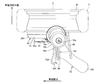
- FIG. 12 is a schematic diagram showing a wiring structure of the in-wheel motor power line according to the first embodiment of the present invention, and shows a state viewed from the inner side in the vehicle width direction.
- FIG. 13 is a schematic diagram showing the first embodiment, and shows a state viewed from the front of the vehicle.
- FIG. 14 is a schematic diagram showing the first embodiment, and shows a state seen from above the vehicle.
- the power line 93 is connected to the power line connecting portion 91 at one end, and extends downward from the one end to constitute the in-wheel motor drive device side region 93d.
- the power line 93 is extended upward from the power line connecting portion 91, and the lower coil spring seat 79 c is bent in the opposite direction and wired so as to extend downward. .
- Each power line 93 further includes a wheel vicinity region 93b between one end of the power line 93 on the power line connecting portion 91 side and the in-wheel motor drive device side region 93d.
- the wheel vicinity region 93b extends in the vertical direction and is wired near the upper portion of the tire T, and is connected to the power line connecting portion 91 side on the lower side and connected to the in-wheel motor drive device side region 93d on the upper side.
- connection portion 93c between the wheel vicinity region 93b and the in-wheel motor drive device side region 93d is turned around the strut 76 and is adjacent to the lower coil spring seat 79c. For this reason, the connection part 93 c is bent without difficulty with a curvature larger than the radius of the strut 76.
- the clearance between the power line 93 and the wheel is the shortest at the connection point 93c.
- the cover 97 is interposed between the trad of the tire T and the connection portion 93c.
- the cover 97 is attached and fixed to the outer peripheral surface of the strut 76, and supports the connection portion 93c from below.
- the wheel vicinity region 93 b and the in-wheel motor drive device side region 93 d extend along the strut 76 and are gripped by a clamp member 96 attached and fixed to the outer peripheral surface of the strut 76. For this reason, the wheel vicinity region 93b and the in-wheel motor drive device side region 93d are not bent away from the strut 76 at least in a portion from the clamp member 96 to the connection portion 93c.
- the clamp member 96 bundles a plurality of power lines 93 and wires them on the inner side surface in the vehicle width direction of the strut 76, and does not restrain the twist of each power line 93.
- the in-wheel motor drive device side region 93d of each power line 93 can be individually twisted.
- the in-wheel motor drive device side region 93d is wired on the lower side of the clamp member 96 and on the outer side in the vehicle width direction than the wheel vicinity region 93b, and extends downward beyond the wheel vicinity region 93b.
- each power line 93 further includes a wheel vicinity region 93b between one end of the power line 93 connected to the power line connecting portion 91 and the in-wheel motor drive device side region 93d.
- the wheel vicinity region 93b extends in the vertical direction, and is connected to the power line connecting portion 91 side on the lower side and connected to the in-wheel motor drive device side region 93d on the upper side.
- the wheel vicinity region 93b since the wheel vicinity region 93b is gripped by the clamp member 96 provided in the suspension device 70, the wheel vicinity region 93b can be held so as to extend in the vertical direction.
- the upper portion of the wheel vicinity region 93b and the upper portion of the in-wheel motor drive device side region 93d that are connected to each other at the connection point 93c are arranged along the lower surface of the lower spring seat 79c.
- Such a portion is referred to as a spring seat vicinity portion 93s in the following description.
- the spring seat vicinity portion 93 s is arranged at a location closest to the outer peripheral surface of the wheel (specifically, the tire T) in the power line 93. That is, the spring seat vicinity portion 93s is disposed between the outer peripheral surface of the tire T of the wheel positioned below and the lower spring seat 79c positioned above.
- the power line 93 When the power line 93 is viewed from the inner side in the vehicle width direction, as shown in FIG. 12, the power line 93 extends from the inner side in the vehicle width direction to the outer side and turns around the strut 76 so as to return to the inner side again.
- the portion 93 s near the spring seat corresponds to a portion turned around the strut 76.
- the spring seat vicinity portion 93s corresponds to a portion bent back in the direction of 180 °.
- the cover 97 is disposed between the outer peripheral surface of the tire T and the spring seat vicinity 93s, and covers the spring seat vicinity 93s from below. Even if foreign matters such as pebbles are splashed up by the outer peripheral surface of the tire T and fly at high speed to the spring seat vicinity portion 93s of the power line 93, the spring seat vicinity portion 93s is protected from the foreign matter by the cover 97.
- the strut 76 is disposed on the inner side in the vehicle width direction than the tire T of the wheel. And the lower end area
- region of the strut 76 has the vehicle width direction outer side surface 76f which faces a wheel, and the vehicle width direction inner side surface 76g located in the opposite side to the vehicle width direction outer side surface 76f.
- the wheel vicinity region 93b and the in-wheel motor drive device side region 93d are wired along the vehicle width direction inner side surface 76g.
- a shielding wall 98 is erected at the boundary between the vehicle width direction outer side surface 76f and the vehicle width direction inner side surface 76g.
- the shielding wall 98 is attached and fixed to the strut 76 between the upper cover 97 and the lower clamp member 96.
- the shielding wall 98 protrudes from the strut 76 in the vehicle front-rear direction and covers the wheel vicinity region 93b and the in-wheel motor drive device side region 93d. For this reason, the wheel vicinity region 93b and the in-wheel motor drive device side region 93d are hidden from the tire T on the outer side in the vehicle width direction.
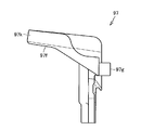
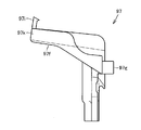
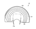
- FIG. 15A is a view showing the cover 97 taken out from the first embodiment, and shows a state seen from above.
- FIG. 15B is a view showing the cover 97 taken out from the first embodiment, and shows a state seen from the inner side in the vehicle width direction.
- FIG. 16A is a view showing the cover 97 taken out, showing a state seen in the vehicle front-rear direction and corresponding to FIG.
- the cover 97 has a plate-like portion 97f, a gripping portion 97g, and a peripheral wall portion 97k. As shown in FIG. 15A, the plate-like portion 97f and the grip portion 97g are integrally coupled. As shown in FIG. 15B, the plate-like portion 97f and the peripheral wall portion 97k are integrally coupled.
- the grip portion 97 g is disposed between the lower shielding wall 98 and the upper lower spring seat 79 c and is fixedly attached to the strut 76.
- the plate-like portion 97f extends obliquely outward and upward in the vehicle width direction from the grip portion 97g, and the surface of the plate-like portion 97f is inclined.
- the plate-like portion 97f of the cover 97 has a semicircular shape corresponding to half of the lower spring seat 79c, and has an arcuate edge and a straight edge.
- a peripheral wall portion 97k is erected on the arc-shaped edge.
- the plate-like portion 97f is provided so as to overlap the lower surface of the lower spring seat 79c and covers at least the outer half in the vehicle width direction of the lower spring seat 79c.
- the peripheral wall portion 97k protrudes upward from the upper surface of the plate-like portion 97f and comes into contact with the outer peripheral edge of the lower spring seat 79c.
- the lower spring seat 79c, the peripheral wall portion 97k, and the plate-like portion 97f which are three-side walls, define a space for accommodating the spring seat vicinity portion 93s of the power line 93.
- the peripheral wall portion 97k shown in FIG. 16A is arranged so as to snuggle up to the outer peripheral edge of the lower spring seat 79c. Or in the cover 97 of the modification shown to FIG. 16B, the nail
- a grip portion 97g is provided on the linear edge of the plate-like portion 97f of the cover 97.
- the grip portion 97g is formed in a C shape, and is attached and fixed to the strut 76 so that at least the outer surface 76f in the vehicle width direction of the strut 76 is held in a C shape above the clamp member 96.
- the plurality of power lines 93 are wired along the upper surface of the cover 97 between the lower cover 97 and the upper lower spring seat 79c.
- the upper surface of the cover 97 is a flat or curved surface as shown in FIG.
- FIG. 17 shows a modification of the cover 97.
- a plurality of grooves 97j that are curved and extend around the grip portion 97g are formed.
- Each groove 97j accepts a portion 93s near the spring seat of each power line 93 along the upper surface of the cover 97.
- the wheel which consists of the wheel wheel W and the tire T
- the in-wheel motor drive device 10 which is arrange
- a lower spring seat 79c that is disposed at an interval and supports the end of the spring 78, and a power line that extends from the in-wheel motor driving device 10 to the vehicle body 101 via the lower spring seat 79c and the outer peripheral surface of the wheel. 93 and between the lower spring seat 79c of the power line 93 and the wheel outer peripheral surface. And a cover 97 for covering the pulling sheet vicinity of 93s.
- the cover 97 is provided between the lower wheel (tire T) outer peripheral surface and the upper spring seat vicinity portion 93 s to protect the spring seat vicinity portion 93 s of the power line 93. Accordingly, even if the outer peripheral surface of the wheel rolls up foreign matters such as pebbles and the foreign matters fly at high speed toward the spring seat vicinity portion 93s, the foreign matter does not collide with the spring seat vicinity portion 93s.
- FIG. 18 shows a wiring structure of an in-wheel motor power line as a reference example.
- the reference example in FIG. 18 represents a state viewed from the front of the vehicle.
- no cover is provided between the outer peripheral surface of the lower wheel (tire T) and the upper spring seat vicinity 93s.
- the spring seat vicinity portion 93s faces the wheel outer peripheral surface, that is, the tire T.
- the outer peripheral surface of the tire T rolls up foreign matter such as pebbles, the foreign matter may collide with the spring seat vicinity portion 93s and the power line may be damaged.
- the struts 76 are arranged on the inner side in the vehicle width direction than the wheels.
- the lower end region of the strut 76 has a vehicle width direction outer side surface 76f as one side surface facing the wheel, and a vehicle width direction inner side surface 76g as another side surface located on the opposite side of the vehicle width direction outer side surface 76f.
- a wheel vicinity region 93 b from one end connected to the in-wheel motor drive device 10 to the spring seat vicinity portion 93 s is wired along the vehicle lateral direction inner side surface 76 g of the strut 76.
- the strut 76 can be interposed between a wheel and the wheel vicinity area
- the shielding wall 98 is erected at the boundary between the vehicle width direction outer side surface 76f and the vehicle width direction inner side surface 76g in the lower end region of the strut 76, the foreign matter flying from the wheels. Can be made more difficult to collide with the wheel vicinity region 93b.
- the cover 97 includes the plate-like portion 97f having a shape corresponding to half of the lower spring seat 79c, and the plate-like portion 97f covers more than half of the lower spring seat 79c. The portion near the spring seat 93s wired between 97f and the lower spring seat 79c can be reliably protected.
- the cover 97 further includes a C-shaped gripping portion 97g formed at the edge of the plate-shaped portion 97f, and the gripping portion 97g is attached and fixed to the strut 76 so as to hold the side surface of the strut 76.
- the Accordingly, the cover 97 can protect the power line 93 in cooperation with the strut 76.
- the plate-like portion 97f and the lower spring seat 79c are provided with claws and holes, respectively. Since these claws and holes engage with each other as the engaging portion and the engaged portion, the plate-like portion 97f is connected to the lower spring seat 79c. Even if a downward force is applied to the plate-like portion 97f from the power line 93, the plate-like portion 97f is not deformed or the plate-like portion 97f does not approach the outer peripheral surface of the tire T of the wheel.
- a groove 97j is formed on the upper surface of the plate-like portion 97f to receive the spring seat vicinity portion 93s of the power line 93 along the upper surface of the plate-like portion 97f.
- the three spring seat vicinity portions 93s are respectively received along the same number of grooves 97j, and the spring seat vicinity portions 93s can be held.
- the groove 97j extends while being curved with the grip portion 97g as the center, the plurality of spring seat vicinity portions 93s can be aligned concentrically with the grip portion 97g as the center.
- the clamp member 96 is disposed on the inner side in the vehicle width direction of the strut 76 as shown in FIG. 13, and holds a plurality of power lines extending in the vertical direction as shown in FIG. Specifically, the clamp member 96 holds three wheel vicinity regions 93b and three in-wheel motor drive device side regions 93d.
- a shock absorber 77 provided in the upper end region of the strut 76 is a combination of a damper and a spring 78. The damper is installed in the upper end region of the strut 76.
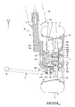
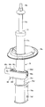
- FIG. 19 is a perspective view showing the strut and the clamp member taken out from the first embodiment.
- the clamp member 96 has a plurality of through holes 96h penetrating the clamp member 96 in the vertical direction, and a power line 93 is passed through each through hole 96h. Thereby, each power line 93 is hold
- the damper includes an upper rod 77b and a lower cylindrical shaft portion 77c. The shaft portion 77c slidably receives the rod 77b.
- a lower spring seat 79c and a clamp member 96 are provided on the side surface of the shaft portion 77c.
- a damper bracket 76d is provided at the lower end portion of the shaft portion 77c, that is, the lower end portion 76c of the strut 76.
- the damper bracket 76d is fixed to the lower end of the shaft portion 77c and produces an effect below the shaft portion 77c.
- the damper bracket 76d has a plate-like in-wheel motor connecting portion 76e protruding in the outer diameter direction of the shaft portion 77c.
- a through hole 76f is formed in the in-wheel motor connecting portion 76e.
- a bolt (not shown) passes through the through hole 76f, and a shaft portion of the bolt is screwed into a female screw hole (not shown) formed in the in-wheel motor drive device 10, whereby the damper bracket 76d is attached to the in-wheel motor drive device 10. Fixed.
- the clamp member 96 is disposed above the damper bracket 76d.
- the lower spring seat 79 c is disposed above the clamp member 96.
- FIG. 21 is a perspective view showing the clamp member taken out from the first embodiment.
- FIG. 22 is an exploded perspective view of the clamp member and corresponds to FIG.
- the clamp member 96 includes a pair of base members 96c and 96d, a block 96e, and a wall member 96f.
- One base member 96c is formed by bending a steel strip, and a ball joint connecting portion 96s is formed at one end.
- a hole 96o for receiving a ball stud is formed in the ball joint connecting portion 96s.
- the ball joint connecting portion 96s will be described in detail together with a stabilizer described later.
- a semi-cylindrical recess 96v that receives the shaft portion 77c at the lower end of the damper is formed.
- a plurality of through holes 96u are formed in both end portions 96x of the base member 96c located on both sides of the semi-cylindrical recess 96v.
- the other base member 96d is basically a rectangular parallelepiped block in which a semi-cylindrical recess 96v is formed on one side surface of the rectangular parallelepiped.
- the other side surface of the rectangular parallelepiped is formed flat.
- a plurality of female screw holes are formed in both end portions 96w located with the semi-cylindrical recess 96v interposed therebetween.
- the base member 96d is made of resin or light metal including aluminum.
- the block 96e is an elastic member made of rubber or sponge and has a plurality of through holes 96h. Six through holes 96h are provided, and are arranged in parallel to each other with an interval from one end to the other end of the block 96e. A notch 96j is provided from one side surface 96i of the block 96e to each through hole 96h. A pair of flange portions 96l and 96l are formed in the vicinity of both end openings 96k of the through hole 96h. The pair of flange portions 96l extend in parallel to each other from one end of the block 96e to the other end of the block 96e through the other side of the block 96e.
- a wide groove 96m is formed between the flange portions 96l and 96l.
- the wide groove 96m continues along the one end face 96z of the block 96e, the other side face of the block 96e, and the other end face of the block 96e.
- the wall member 96f is formed by bending a steel strip.
- the pair of end wall portions 96p, 96p facing each other in the horizontal direction and the edge of one end wall portion 96p to the edge of the other end wall portion 96p are horizontal.
- the wall member 96f has a shape corresponding to the above-described wide groove 96m.
- a round hole 96a and a long hole 96r are formed through each end wall portion 96p.
- female screw holes 96y and claws 96t are formed on both end surfaces of the other base member 96d described above. The arrangement of the female screw hole 96y and the claw 96t corresponds to the arrangement of the round hole 96a and the long hole 96r of the wall member 96f.
- each notch 96j of the block 96e is closed.
- one side surface of the block 96e is brought into contact with the other flat side surface of the base member 96d, and the wall member 96f is applied to the wide groove 96m on the other side surface of the block 96e.
- the long hole 96r of the wall member 96f engages with the claw 96t of the base member 96d, and the round hole 96a of the wall member 96f matches the female screw hole 96y of the base member 96d.
- the bolt 96g is passed through each round hole 96a of the wall member 96f, and the shaft portion of the bolt 96g is screwed into the female screw hole 96y of the base member 96d, whereby the wall member 96f is attached and fixed to the base member 96d.
- the block 96e is held by the wall member 96f and restrained so as not to drop off from the base member 96d, and the clamp member 96 shown in FIG. 21 is assembled.
- one clamp member 96 holds a plurality of power lines 93.
- the plurality of power lines 93 extend in the vertical direction and are connected to the in-wheel motor drive device 10 side at the lower side and the wheel vicinity region 93b connected to the vehicle body 101 side at the upper side, and the upper side extending in the vertical direction
- the in-wheel motor drive device side region 93d is connected to the vehicle body 101 side below.
- the clamp member 96 is an assembly member common to the plurality of power lines 93 and collectively holds the plurality of wheel vicinity regions 93b and the plurality of in-wheel motor drive device side regions 93d.
- the clamp member 96 is arranged so as to overlap with the rim portion Wr of the wheel W when viewed in the direction of the axis O, that is, the axle direction. Further, the clamp member is disposed so as to overlap with the turning axis K.
- a clamp member 96 may be provided on the damper bracket 76d as in the modification shown in FIG. In the modification, the base member 96c may be integrally coupled to the damper bracket 76d, or the base member 96c may be attached and fixed to the damper bracket 76d as another member.
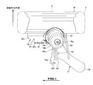
- FIG. 23 is a schematic diagram showing a wiring structure of an in-wheel motor power line according to the second embodiment of the present invention, and shows a state viewed from the inner side in the vehicle width direction.
- FIG. 24 is a schematic diagram showing the second embodiment, and shows a state seen from the front of the vehicle.
- FIG. 25 is a schematic diagram showing the second embodiment, and shows a state seen from above the vehicle.
- 2nd Embodiment about the structure which is common in embodiment mentioned above, the same code
- the signal line terminal box 25 is provided so as to protrude inward in the vehicle width direction from the motor casing cover 25v.
- the signal line terminal box 25 is provided in the motor unit 21 so as not to protrude.
- heat radiation fins 25f are provided over substantially the entire surface. The heat radiation fins 25f are also formed on the power line terminal box 25b.
- the heat dissipating fins 25f extend straight in the vehicle front-rear direction, and many radiating fins 25f are provided at intervals in the vertical direction. While the electric vehicle is traveling, the traveling wind flows smoothly between the plurality of heat radiation fins 25f, 25f parallel to each other. Therefore, the cooling efficiency of the motor unit 21 is improved.
- FIG. 26 is a schematic view showing a wiring structure of an in-wheel motor power line according to the third embodiment of the present invention, and shows a state viewed from the inner side in the vehicle width direction.
- FIG. 27 is a schematic view showing the third embodiment, and shows a state seen from the front of the vehicle.
- FIG. 28 is a schematic diagram showing the third embodiment, and shows a state viewed from above the vehicle.
- the same components as those in the above-described embodiment are denoted by the same reference numerals, description thereof is omitted, and different configurations are described below.
- a stabilizer and a pair of stabilizer links are superposed on the first embodiment described above.
- the in-wheel motor drive device 10, the suspension member 70, the damper built-in strut 76, the power line 93, the clamp member 96, and the stabilizer link 108 of the third embodiment are respectively provided on both sides of the vehicle body 101 in the vehicle width direction. It is provided and makes a pair. These pairs are arranged symmetrically with respect to a reference plane of the electric vehicle that passes through the center of the vehicle body 101 in the vehicle width direction and extends in the vehicle longitudinal direction and the vertical direction.
- the pair of stabilizer links 108 extend in the vertical direction.
- Stabilizer 104 extends in the vehicle width direction, and both end portions 105 change direction and extend forward of the vehicle.
- One end 106 of the stabilizer 104 is connected to the lower end 109 of one stabilizer link 108 via a ball joint 107.
- the other end of the stabilizer 104 is connected to the lower end 109 of the other stabilizer link 108 via a ball joint.
- a socket that accommodates the ball portion of the ball joint 107 is formed at the lower end 109, and a ball stud of the ball joint 107 is attached and fixed to one end 106 of the stabilizer 104.
- each stabilizer link 108 is connected to the clamp member 96 via the ball joint 111.
- a socket that accommodates the ball portion of the ball joint 111 is formed in the upper end 110 so that the ball portion 111 can freely move, and the ball stud of the ball joint 111 is fixedly attached to the hole 96o of the ball joint connecting portion 96s of the clamp member 96.
- the stabilizers 104 and 1 transmits the expansion and contraction of the strut 76 on one side in the vehicle width direction to the strut 76 on the other side in the vehicle width direction.
- the road surface step on one side in the vehicle width direction is received by the struts 76 on both sides in the vehicle width direction to reduce rolling.
- the wiring structure of the in-wheel motor power line according to the present invention is advantageously used in electric vehicles and hybrid vehicles.
Landscapes
- Engineering & Computer Science (AREA)
- Mechanical Engineering (AREA)
- Chemical & Material Sciences (AREA)
- Combustion & Propulsion (AREA)
- Transportation (AREA)
- Arrangement Or Mounting Of Propulsion Units For Vehicles (AREA)
Abstract
本発明は、車輪を駆動するインホイールモータ駆動装置と、上端部(77b)および下端部(77c)を有し上端部が車体側メンバと連結し下端部がインホイールモータ駆動装置と連結するダンパ(77)と、インホイールモータ駆動装置から車体まで延びる動力線と、ダンパの下端部に設けられて動力線の途中部分を保持するクランプ部材(96)とを備える。
Description
本発明は、インホイールモータ駆動装置から車体まで延びて車体からインホイールモータ駆動装置に電力を供給する動力線に関する。
電動車両の車輪内部にインホイールモータを設け、該車輪をインホイールモータで駆動する技術が従来知られている。かかる電動車両では、車体にエンジンやモータを搭載する必要がなく、居室空間や荷室空間等、車体の内部空間を大きくすることができる点で有利である。電動車両の車体には、サスペンション装置を介して、インホイールモータが連結される。また車体には、インホイールモータの制御部、バッテリ、およびインバータが搭載される。そしてサスペンション装置のばね下(車輪側)に連結されるインホイールモータと、サスペンション装置のばね上(車体側)に搭載されるインバータとを動力線で接続する。インバータからインホイールモータに電力を供給する動力線としては従来、例えば、特許4511976号公報(特許文献1)に記載のごときものが知られている。
サスペンション装置の作用によって、インホイールモータは車体に対して上下方向に変位し、あるいは左右方向に転舵する。このため動力線に無理な屈曲が発生しないよう、動力線の途中部分を適切に支持する必要がある。特許文献記載の動力線配線構造では、動力線の途中部分を、クランプ部材によってインホイールモータの端面に取り付ける。また特許文献記載のインホイールモータの表面には複数のフィンが立設される。
しかし、上記従来のような配線構造にあっては、さらに改善すべき点があることを本発明者は見いだした。つまりインホイールモータ表面にクランプ部材を取り付けているため、当該取り付け箇所にはフィンを設けることができない。したがって、インホイールモータに十分な数の冷却用フィンを設けることができなかった。
本発明は、上述の実情に鑑み、インホイールモータの表面にクランプ部材を設けることなく、動力線の途中部分を支持することができる配線構造を提供することを目的とする。
この目的のため本発明によるインホイールモータ動力線の配線構造は、車輪を駆動するインホイールモータ駆動装置と、上端部および下端部を有し上端部が車体側メンバと連結し下端部がインホイールモータ駆動装置と連結するダンパと、記インホイールモータ駆動装置から車体まで延びる動力線と、ダンパの下端部に設けられて動力線の途中部分を保持するクランプ部材とを備える。
かかる本発明によれば、動力線の途中部分を保持するクランプ部材を、インホイールモータ駆動装置から離隔して配置することから、インホイールモータ駆動装置の表面に十分な数の冷却用フィンを設けることができる。
本発明の一実施形態としてダンパは、上下方向に延びて該上下方向に伸縮可能なストラットに含まれ、ストラットの伸縮を減衰させる。他の実施形態として、ダンパおよびサスペンションアームの組み合わせでインホイールモータ駆動装置を車体側メンバに連結してもよい。
本発明の好ましい実施形態としてインホイールモータ駆動装置は、ストラットの上端部と交差して上下方向に延びる転舵軸線回りに転舵可能である。他の実施形態としてインホイールモータ駆動装置は、転舵しない非旋回輪を駆動するものであってもよい。
本発明のさらに好ましい実施形態としてクランプ部材は、動力線の外周を包囲する弾性部材を含む。かかる実施形態によれば、ねじれや若干の変位を許容して、動力線に作用する屈曲を緩和することができる。他の実施形態として、O字状やC字状の金属部材で動力線の途中部分を包囲してもよい。
本発明の一実施形態として、弾性部材は複数の貫通孔を有するブロックであり、各貫通孔に動力線を通される。かかる実施形態によれば、複数の動力線を整然と配列することができる。他の実施形態として、1個の貫通孔に複数の動力線を通してもよい。
本発明の一実施形態としてクランプ部材は、ダンパ下端部を挟持する1対の基部材と、水平方向に互いに向き合う1対の端壁部、および一方の端壁部から他方の端壁部まで水平方向に延びる中間壁部を有し1対の端壁部が基部材に取り付けられて弾性部材の側面を抱えるように拘束する金属製の壁部材とをさらに含む。かかる実施形態によれば、動力線の水平方向移動を規制することができる。
本発明の一実施形態として、車輪の車軸方向にみてクランプ部材は、車輪の車輪ホイールリムと重なるよう配置される。かかる実施形態によれば動力線が屈曲して車輪と干渉することを防止できる。他の実施形態として、車輪の車軸方向にみてクランプ部材は、車輪の車輪ホイールリムから離れて配置されてもよい。
本発明の一実施形態として、車輪の車軸方向にみてクランプ部材は、転舵軸線と重なるよう配置される。かかる実施形態によれば、インホイールモータ駆動装置が転舵する際の動力線の屈曲を少なくすることができる。他の実施形態として、車輪の車軸方向にみてクランプ部材は、車輪の車輪ホイールリムから車両前後方向にずらして配置される。
本発明の一実施形態としてダンパ下端部は、軸部と、該軸部に取付固定されて該軸部から下方へ延びインホイールモータ駆動装置と結合するためのインホイールモータ連結部を有するダンパブラケットを含み、クランプ部材は軸部に設けられる。他の実施形態として、クランプ部材はダンパブラケットに設けられてもよい。
本発明の一実施形態として動力線は、上下方向に延びて下方でインホイールモータ駆動装置側と接続し上方で車体側と接続する第1領域と、上下方向に延びて上方でインホイールモータ駆動装置側と接続し下方で車体側と接続する第2領域とを含み、クランプ部材は第1領域および第2領域を把持する。かかる実施形態によれば動力線を、ダンパ下端部に沿って、折り返すように配線することができる。
本発明の一実施形態としてインホイールモータ駆動装置と、ダンパと、動力線と、クランプ部材は車体の車幅方向両側にそれぞれ配置され、車体の車幅方向一側から他側まで延びるスタビライザと、車体の車幅方向両側にそれぞれ配置される1対のスタビライザリンクとをさらに備え、スタビライザリンクは、一端でスタビライザの端部と連結し、他端でクランプ部材と連結する。かかる実施形態によれば、スタビライザリンクをダンパ下端部に連結するための部品を少なくすることができる。他の実施形態としてスタビライザリンクの他端は、クランプ部材から離れて、ダンパ下端部に連結されてもよい。
本発明は、インホイールモータ動力線を含むインホイールモータ駆動装置としても成立可能である。すなわち本発明のインホイールモータ駆動装置は、車輪と結合する車輪ハブと、車輪ハブを駆動するモータ回転軸、外郭をなすケーシング、およびケーシングに設けられる動力線接続部を有するモータ部と、一端が動力線接続部と接続し、他端がケーシング外部の車体まで延び、車体からモータ部へ電力を供給する屈曲可能な動力線とを備え、上下方向に延びるダンパのうち該ダンパの下端部と連結する。そして動力線の途中部分は、ダンパ下端部に設けられるクランプ部材に保持される。
かかる本発明によれば、動力線の途中部分を保持するクランプ部材が、インホイールモータ駆動装置ではなくダンパ下端部に設けられることから、インホイールモータ駆動装置の表面に十分な数の冷却用フィンを設けることができる。
このように本発明によれば、インホイールモータ駆動装置の表面に十分な数の冷却用フィンを設けることができる。したがってインホイールモータ駆動装置の冷却効果を向上させることができる。
以下、本発明の実施の形態を、図面に基づき詳細に説明する。図1は、参考例になるインホイールモータ動力線の配線構造を示す模式図であり、車幅方向内側からみた状態を表す。図2は参考例を示す模式図であり、車両前方からみた状態を表す。図3は参考例を示す模式図であり、上方からみた状態を表す。参考例では、車体101(図2に車体の車幅方向外側部分のみ示す)の車幅方向外側に車輪ホイールW、インホイールモータ駆動装置10、およびサスペンション装置70が配置される。また車輪ホイールW、インホイールモータ駆動装置10、およびサスペンション装置70は車体101の車幅方向両側に左右対称に配置され、電動車両を構成する。
車輪ホイールWの外周には仮想線で示すタイヤTが嵌合する。車輪ホイールWおよびタイヤTは車輪を構成する。車輪ホイールWのリム部Wrは、車輪の内空領域を区画する。かかる内空領域にはインホイールモータ駆動装置10が配置される。インホイールモータ駆動装置10は車輪ホイールWと連結して車輪を駆動する。
サスペンション装置70はストラット式サスペンション装置であり車幅方向に延びるロアアーム71と、ロアアーム71よりも上方に配置されて上下方向に延びるストラット76を含む。ストラット76は車輪ホイールWおよびインホイールモータ駆動装置10よりも車幅方向内側に配置され、ストラット76の下端がインホイールモータ駆動装置10と結合し、ストラット76の上端が車輪ホイールWよりも上方で車体101と連結する。なおストラット76と、車輪ホイールWの上部と、インホイールモータ駆動装置10の上部は、車体101の車幅方向外側に形成されるホイールハウス102に収容される。
ストラット76は上端領域にショックアブソーバ77を内蔵して上下方向に伸縮可能なサスペンション部材である。ショックアブソーバ77の外周には仮想線で概略を示すコイルスプリング78が配置され、ストラット76に作用する上下方向の軸力を緩和する。ストラット76の上端部および中央部には、コイルスプリング78の上端および下端を挟んで保持する1対のコイルスプリングシート79b,79cが設けられる。ショックアブソーバ77の内部にはストラット76に作用する軸力を減衰させるダンパが設けられる。
ロアアーム71は、インホイールモータ駆動装置10の軸線Oよりも下方に配置されるサスペンション部材であって、車幅方向外側端72および車幅方向内側端73d,73fを含む。ロアアーム71は、車幅方向外側端72で、ボールジョイント60を介してインホイールモータ駆動装置10に連結される。またロアアーム71は車幅方向内側端73d,73fで図示しない車体側メンバに連結される。車幅方向内側端73d,73fを基端とし、車幅方向外側端72を遊端として、ロアアーム71は上下方向に揺動可能である。なお車体側メンバとは説明される部材からみて車体側に取り付けられる部材をいう。車幅方向外側端72とストラット76の上端76aを結ぶ直線は、上下方向に延びて転舵軸線Kを構成する。転舵軸線Kは基本的には上下方向に延びるが、車幅方向および/または車両前後方向に若干傾斜してもよい。なお図中において車幅方向内側端73d,73fを区別しない場合、単に符号73を付してある。
ロアアーム71よりも上方にはタイロッド80が配置される。タイロッド80は車幅方向に延び、タイロッド80の車幅方向外側端がインホイールモータ駆動装置10と回動可能に連結する。タイロッド80の車幅方向内側端は図示しない操舵装置と連結する。操舵装置はタイロッド80を車幅方向に進退動させて、インホイールモータ駆動装置10および車輪ホイールWを転舵軸線K回りに転舵させる。
次にインホイールモータ駆動装置につき説明する。
図4は図1~図3に示すインホイールモータ駆動装置を取り出して示す模式図であり、車幅方向外側からみた状態を表す。図5はインホイールモータ駆動装置を示す横断面図であり、車幅方向外側からみた状態を模式的に表す。図5中、減速部内部の各歯車は歯先円で表され、個々の歯を図略する。図6はインホイールモータ駆動装置を模式的に示す展開断面図である。図6で表される切断面は、図5に示す軸線Mおよび軸線Nfを含む平面と、軸線Nfおよび軸線Nlを含む平面と、軸線Nlおよび軸線Oを含む平面とを、この順序で接続した展開平面である。図7は、インホイールモータ駆動装置を示す縦断面図であり、車輪およびサスペンション装置とともに表す。図面の煩雑を避けるため図7中、減速部内部の各歯車は図略される。
インホイールモータ駆動装置10は、図6に示すように仮想線で表される車輪ホイールWの中心と連結する車輪ハブ軸受部11と、車輪の車輪ホイールWを駆動するモータ部21と、モータ部の回転を減速して車輪ハブ軸受部11に伝達する減速部31を備え、電動車両のホイールハウス(図示せず)に配置される。モータ部21および減速部31は、車輪ハブ軸受部11の軸線Oと同軸に配置されるのではなく、図5に示すように車輪ハブ軸受部11の軸線Oからオフセットして配置される。インホイールモータ駆動装置10は、公道で電動車両を時速0~180km/hで走行させることができる。
車輪ハブ軸受部11は、図6に示すように車輪ホイールWと結合する車輪ハブとしての外輪12と、外輪12の中心孔に通される内側固定部材13と、外輪12と内側固定部材13との環状隙間に配置される複数の転動体14を有し、車軸を構成する。内側固定部材13は、非回転の固定軸15と、1対のインナーレース16と、抜け止めナット17と、キャリア18とを含む。固定軸15は根元部15rが先端部15eよりも大径に形成される。インナーレース16は、根元部15rと先端部15eの間で、固定軸15の外周に嵌合する。抜け止めナット17は固定軸15の先端部15eに螺合して、抜け止めナット17と根元部15rの間にインナーレース16を固定する。
固定軸15は軸線Oに沿って延び、減速部31の外郭をなす本体ケーシング43を貫通する。固定軸15の先端部15eは、本体ケーシング43の正面部分43fに形成される開口43pを貫通し、正面部分43fよりも車幅方向外側へ突出する。固定軸15の根元部15rは、本体ケーシング43の背面部分43bよりも車幅方向内側から、背面部分43bに形成される開口43qを貫通する。なお正面部分43fと背面部分43bは軸線O方向に間隔を空けて互いに向き合う壁部分である。根元部15rにはキャリア18が取付固定される。キャリア18は本体ケーシング43の外部でサスペンション装置70およびタイロッド80と連結する。
転動体14は、軸線O方向に離隔して複列に配置される。軸線O方向一方のインナーレース16の外周面は、第1列の転動体14の内側軌道面を構成し、外輪12の軸線O方向一方の内周面と対面する。軸線O方向他方のインナーレース16の外周面は、第2列の転動体14の内側軌道面を構成し、外輪12の軸線O方向他方の内周面と対面する。以下の説明において、車幅方向外側(アウトボード側)を軸線方向一方ともいい、車幅方向内側(インボード側)を軸線方向他方ともいう。図6の紙面左右方向は、車幅方向に対応する。外輪12の内周面は転動体14の外側軌道面を構成する。
外輪12の軸線O方向一方端にはフランジ部12fが形成される。フランジ部12fはブレーキディスクBDおよび車輪ホイールWのスポーク部Wsと同軸に結合するための結合座部を構成する。外輪12はフランジ部12fでブレーキディスクBDおよび車輪ホイールWと結合して、車輪ホイールWと一体回転する。なお図示しない変形例として、フランジ部12fは周方向に間隔を空けて外径側へ突出する突出部であってもよい。
モータ部21は図6に示すように、モータ回転軸22、ロータ23、ステータ24、モータケーシング25、モータケーシングカバー25vを有し、この順序でモータ部21の軸線Mから外径側へ順次配置される。モータ部21は、インナーロータ、アウターステータ形式のラジアルギャップモータであるが、他の形式であってもよい。例えば図示しなかったがモータ部21はアキシャルギャップモータであってもよい。
モータ回転軸22およびロータ23の回転中心になる軸線Mは、車輪ハブ軸受部11の軸線Oと平行に延びる。つまりモータ部21は、車輪ハブ軸受部11の軸線Oから離れるようオフセットして配置される。モータ回転軸22の先端部を除いたモータ部21の大部分の軸線方向位置は、図6に示すように内側固定部材13の軸線方向位置と重ならない。モータケーシング25は筒状であり、軸線M方向一方端で本体ケーシング43の背面部分43bと結合し、軸線M方向他方端で蓋状のモータケーシングカバー25vに封止される。モータ回転軸22の両端部は、転がり軸受27,28を介して、モータケーシング25およびモータケーシングカバー25vに回転自在に支持される。モータ部21は外輪12および車輪を駆動する。
図1に示すようにインホイールモータ駆動装置10の上部には動力線端子箱25bが設けられる。動力線端子箱25bはモータケーシング25(図6)の上部およびモータケーシングカバー25v(図6)の上部に跨って形成され、複数の動力線接続部91を有する。動力線端子箱25bは、3個の動力線接続部91を有し、三相交流電力を受電する。各動力線接続部91には動力線93の一端が接続される。動力線93の芯線は、動力線端子箱25b内部で、ステータ24のコイルから延びる導線と接続する。
モータケーシングカバー25vの中心部には信号線端子箱25cが形成される。信号線端子箱25cは、動力線端子箱25bから離隔する。信号線端子箱25cは図6に示すように軸線Mと交差するように配置される。信号線端子箱25cは回転角センサ84を収容する。回転角センサ84は、モータ回転軸22の軸線方向端部に設けられて、モータ回転軸22の回転角度を検出する。信号線端子箱25cには信号線接続部85が設けられる。信号線接続部85は信号線端子箱25cの壁部分と、該壁部分を貫通する貫通孔と、この貫通孔に近接する壁部分に設けられた雌ねじ孔(図示せず)を有する。貫通孔にはスリーブ86および信号線87が通される。スリーブ86は、筒状体であり、信号線87の外周に密着して、信号線87を保護し、貫通孔と信号線87との環状隙間を封止する。スリーブ86の外周面には、スリーブ外径方向に突出する舌部86tが形成される。舌部86tおよび信号線接続部85の雌ねじ孔には図6に示さないボルトがねじ込まれ、これによりスリーブ86は信号線接続部85に取付固定される。
信号線87は導電体からなる複数の芯線と、複数の芯線を束ねるように被覆する絶縁体の被覆部からなり、屈曲可能である。信号線87の一端は、信号線接続部85と接続する。図示はしなかったが信号線87は一端から車体101(図2)まで延びる。
各動力線接続部91も、信号線接続部85と同様に構成され、動力線端子箱25bの壁部分と、該壁部分を貫通する貫通孔と、この貫通孔に近接する壁部分に設けられた雌ねじ孔(図示せず)を有する。貫通孔にはスリーブ92および動力線93の一端部が通される。スリーブ92および動力線93は、動力線接続部91の貫通孔から車体101側へ延出する。動力線93はスリーブ92に通されて、スリーブ92から車体101側へ延出する。各スリーブ92は、筒状体であり、動力線93の外周に密着して、動力線93を保護する。また各スリーブ92は、動力線93の一端部とともに動力線接続部91の貫通孔に差込固定されて、動力線93の一端部を保持し、さらに動力線93と貫通孔との環状隙間を封止する。スリーブ92を抜け止めするため、スリーブ92の外周面には、スリーブ外径方向に突出する舌部92tが形成される。舌部92tおよび動力線接続部91の雌ねじ孔には図1に示すボルト91bがねじ込まれ、これによりスリーブ92は動力線接続部91に取付固定される。
減速部31は、入力軸32、入力歯車33、中間歯車34、中間軸35、中間歯車36、中間歯車37、中間軸38、中間歯車39、出力歯車40、出力軸41、および本体ケーシング43を有する。入力軸32は、モータ回転軸22の先端部22eよりも大径の筒状体であって、モータ部21の軸線Mに沿って延びる。先端部22eは入力軸32の軸線M方向他方端部の中心孔に受け入れられて、入力軸32はモータ回転軸22と同軸に結合する。入力軸32の両端は転がり軸受42a,42bを介して、本体ケーシング43に支持される。入力歯車33は、モータ部21よりも小径の外歯歯車であり、入力軸32と同軸に結合する。具体的には入力歯車33は、入力軸32の軸線M方向中央部の外周に一体形成される。
出力軸41は、外輪12の円筒部分よりも大径の筒状体であって、車輪ハブ軸受部11の軸線Oに沿って延びる。外輪12の軸線O方向他方端は、出力軸41の軸線O方向一方端の中心孔に受け入れられて、出力軸41は外輪12と同軸に結合する。出力軸41の軸線O方向両端部外周には転がり軸受44,46が配置される。出力軸41の軸線O方向一方端は転がり軸受44を介して、本体ケーシング43の正面部分43fに支持される。出力軸41の軸線O方向他方端は転がり軸受46を介して、本体ケーシング43の背面部分43bに支持される。出力歯車40は外歯歯車であり、出力軸41と同軸に結合する。具体的には出力歯車40は出力軸41の軸線O方向他方端の外周に一体形成される。
2本の中間軸35,38は入力軸32および出力軸41と平行に延びる。つまり減速部31は四軸の平行軸歯車減速機であり、出力軸41の軸線Oと、中間軸35の軸線Nfと、中間軸38の軸線Nlと、入力軸32の軸線Mは互いに平行に延び、換言すると車幅方向に延びる。
各軸の車両前後方向位置につき説明すると、図5に示すように入力軸32の軸線Mは出力軸41の軸線Oよりも車両前方に配置される。また中間軸35の軸線Nfは入力軸32の軸線Mよりも車両前方に配置される。中間軸38の軸線Nlは出力軸41の軸線Oよりも車両前方かつ入力軸32の軸線Mよりも車両後方に配置される。図示しない変形例として入力軸32の軸線Mと、中間軸35の軸線Nfと、中間軸38の軸線Nlと、出力軸41の軸線Oが、この順序で車両前後方向に配置されてもよい。この順序は駆動力の伝達順序でもある。
各軸の上下方向位置につき説明すると、入力軸32の軸線Mは出力軸41の軸線Oよりも上方に配置される。中間軸35の軸線Nfは入力軸32の軸線Mよりも上方に配置される。中間軸38の軸線Nlは中間軸35の軸線Nfよりも上方に配置される。なお複数の中間軸35,38は、入力軸32および出力軸41よりも上方に配置されれば足り、図示しない変形例として中間軸35が中間軸38よりも上方に配置されてもよい。あるいは図示しない変形例として出力軸41が入力軸32よりも上方に配置されてもよい。
中間歯車34および中間歯車36は外歯歯車であり、図6に示すように中間軸35の軸線Nf方向中央部と同軸に結合する。中間軸35の両端部は、転がり軸受45a,45bを介して、本体ケーシング43に支持される。中間歯車37および中間歯車39は外歯歯車であり、中間軸38の軸線Nl方向中央部と同軸に結合する。中間軸38の両端部は、転がり軸受48a,48bを介して、本体ケーシング43に支持される。
本体ケーシング43は、減速部31および車輪ハブ軸受部11の外郭をなし、筒状に形成されて、図5に示すように軸線O、Nf、Nl、Mを取り囲む。また本体ケーシング43は、図7に示すように車輪ホイールWの内空領域に収容される。車輪ホイールWの内空領域はリム部Wrの内周面と、リム部Wrの軸線O方向一端と結合するスポーク部Wsとによって区画される。そして車輪ハブ軸受部11、減速部31、およびモータ部21の軸線方向一方領域が車輪ホイールWの内空領域に収容される。またモータ部21の軸線方向他方領域が車輪ホイールWから軸線方向他方へはみ出す。このように車輪ホイールWはインホイールモータ駆動装置10の大部分を収容する。
図5を参照して本体ケーシング43は、軸線Oの真下部分43cと、出力歯車40の軸線Oから車両前後方向に離れた位置、具体的には入力歯車33の軸線Mの真下で、下方へ突出する部分とを有する。この突出する部分はオイルタンク47を形成し、真下部分43cよりも下方に位置する。
図7を参照して真下部分43cの直下には、キャリア18の下端部18bと、ロアアーム71の車幅方向外側端72が配置され、ロアアーム71の車幅方向外側端72と下端部18bが、ボールジョイント60を介して方向自在に連結される。図5に示すように軸線O方向にみてオイルタンク47は、略垂直な後側壁部43tと、傾斜した前側壁部43uによって区画され、下向きに細くなる三角形状にされる。なお後側壁部43tは間隔を空けてボールジョイント60(図7)と車両前後方向に対面する。前側壁部43uはリム部Wr(図7)のうち前側かつ下側の部分と対面する。
ボールジョイント60は、図7に示すようにボールスタッド61およびソケット62を含む。ボールスタッド61は上下方向に延び、上端に形成されるボール部61bおよび下端に形成されるスタッド部61sを有する。ソケット62は内側固定部材13に設けられて、ボール部61bを摺動可能に収容する。スタッド部61sは、ロアアーム71の車幅方向外側端72を上下方向に貫通する。スタッド部61sの下端外周には雄ねじが形成され、下方からナット72nが螺合することにより、スタッド部61sはロアアーム71に取付固定される。図1に示すようにボールジョイント60は、オイルタンク47の下端よりも上方に位置する。ボールジョイント60およびオイルタンク47は、車輪ホイールWの内空領域に配置され、ボールジョイント60は軸線Oの直下に配置され、オイルタンク47はボールジョイント60から車両前後方向に離れて配置される。またボールジョイント60は、図7に示すように背面部分43bよりも車幅方向外側に配置される。転舵軸線Kはボール部61bのボール中心を通過して上下方向に延び、固定軸15と、タイヤTの接地面Rを交差する。キャリア18の上端部は、ストラット76の下端に取付固定される。
本体ケーシング43は、筒状であり、図6に示すように入力軸32、入力歯車33、中間歯車34、中間軸35、中間歯車36、中間歯車37、中間軸38、中間歯車39、出力歯車40、出力軸41、および車輪ハブ軸受部11の軸線O方向中央部を収容する。本体ケーシング43の内部には潤滑油が封入され、減速部31は潤滑される。入力歯車33、中間歯車34、中間歯車36、中間歯車37、中間歯車39、出力歯車40ははすば歯車である。
本体ケーシング43は、図5に示すように真下部分43cおよびオイルタンク47を含む筒状部分と、図6に示すように減速部31の筒状部分の軸線方向一方側を覆う略平坦な正面部分43fと、減速部31の筒状部分の軸線方向他方側を覆う略平坦な背面部分43bを有する。背面部分43bは、モータケーシング25と結合する。また背面部分43bは、固定軸15と結合する。
正面部分43fには外輪12が貫通するための開口43pが形成される。開口43pには、外輪12との環状隙間を封止するシール材43sが設けられる。このため回転体になる外輪12は、軸線O方向一方端部を除いて本体ケーシング43に収容される。外輪12の軸線O方向他方端部内周面にはシール材43vが配置される。シール材43vは外輪12と背面部分43bの環状隙間を封止する。
小径の入力歯車33と大径の中間歯車34は、減速部31の軸線方向他方側(モータ部21側)に配置されて互いに噛合する。小径の中間歯車36と大径の中間歯車37は、減速部31の軸線方向一方側(フランジ部12f側)に配置されて互いに噛合する。小径の中間歯車39と大径の出力歯車40は、減速部31の軸線方向他方側に配置されて互いに噛合する。このようにして入力歯車33と複数の中間歯車34、36,37,39と出力歯車40は、互いに噛合し、入力歯車33から複数の中間歯車34、36,37,39を経て出力歯車40に至る駆動伝達経路を構成する。そして上述した小径歯車および大径歯車の噛合により、入力軸32の回転は中間軸35で減速され、中間軸35の回転は中間軸38で減速され、中間軸38の回転は出力軸41で減速される。これにより減速部31は減速比を十分に確保する。複数の中間歯車のうち中間歯車34は、駆動伝達経路の入力側に位置する第1中間歯車となる。複数の中間歯車のうち中間歯車39は、駆動伝達経路の出力側に位置する最終中間歯車となる。
図5に示すように、出力軸41、中間軸38、および入力軸32は、この順序で車両前後方向に間隔を空けて配置される。さらに中間軸35および中間軸38は、入力軸32および出力軸41よりも上方に配置される。かかる参考例によれば、車輪ハブになる外輪12の上方に中間軸を配置し得て、外輪12の下方にオイルタンク47の配置スペースを確保したり、外輪12の真下にボールジョイント60(図7)を受け入れる空間を確保したりすることができる。したがって上下方向に延びる転舵軸線Kを車輪ハブ軸受部11に交差して設けることができ、車輪ホイールWおよびインホイールモータ駆動装置10を転舵軸線K回りに好適に転舵させることができる。
次にインホイールモータ動力線の配線構造につき説明する。
図8および図9はインホイールモータ駆動装置および動力線を示す模式図であり、図8は車両後方からみた状態を、図9は車両上方からみた状態を表す。参考例では、インホイールモータ駆動装置10から車体101まで3本の動力線93が延びる。3本の動力線93は三相交流電力を車体101からモータ部21に供給する。各動力線93は導電体からなる芯線と、芯線の全周を覆う絶縁体の被覆部からなり、屈曲可能である。動力線93の一端は、各動力線接続部91およびスリーブ92によって、他端側が車両後方かつ車幅方向内側に向かって斜めの姿勢になるよう保持される。具体的には動力線93の一端部は、転舵していない直進方向の車軸(軸線O)に平行な基準線と角度θ°で交差して延びるよう、斜めに保持される。なお角度θは、インホイールモータ駆動装置10の最大転舵角α°以上90°以下の範囲に含まれる固定値である。なおθ=90°の場合、各動力線93の一端部は、車両前後方向と平行に延びる。動力線93の他端は、車体101に搭載されるインバータ103と接続する。
各動力線93の一端部は、図8に示すように転舵軸線K方向に間隔を空けて整列し、図9に示すように転舵軸線K方向にみて重なるよう配置される。なお各動力線93の一端部は、図9に示すように全ての動力線接続部91が重なるよう配置される。
各動力線93は、動力線93の一端と他端の間に、連続して延びる3つの領域を含む。これら3つの領域のうち、インホイールモータ駆動装置10と接続する側の領域をインホイールモータ駆動装置側領域93dと呼び、車体101と接続する側の領域を車体側領域93fと呼び、インホイールモータ駆動装置側領域93dと車体側領域93fの間の領域を中間領域93eと呼ぶ。
インホイールモータ駆動装置側領域93dは、上下方向に延び、インホイールモータ駆動装置側領域93dの上側でインホイールモータ駆動装置10側と接続し、インホイールモータ駆動装置側領域93dの下側で中間領域93eと接続する。車体側領域93fは、上下方向に延び、車体側領域93fの下側で中間領域93eと接続し、車体側領域93fの上側で車体101側と接続する。中間領域93eは、中間領域93eの両側を上方とし中間領域93eの中間部分を下方として湾曲して延びる。
各動力線接続部91と接続する各動力線93の一端部は、インホイールモータ駆動装置側領域93dに向かって水平方向に延出するが、間もなく下方へ向きを変えて延び、インホイールモータ駆動装置側領域93dの上側に連なる。インホイールモータ駆動装置側領域93dは、クランプ部材によって把持されない。
図2に示すように複数の動力線93は、車体側領域93fよりも他端側で、クランプ部材94に束ねられ、上下方向に延びるよう保持される。このため車体側領域93fは、クランプ部材によって把持されることなく、クランプ部材94よりも下側で上下方向に延びる。クランプ部材94はブラケット95を介して車体101に取付固定される。ブラケット95をホイールハウス102よりも車幅方向内側に配置することにより、車体側領域93fをホイールハウス102よりも車幅方向内側に配線することができる。そしてホイールハウス102を迂回するように動力線93を配線し得るのみならず、ホイールハウス102の壁面をインホイールモータ駆動装置10に近づけてホイールハウス102を小さくすることができる。
図2に示すように、クランプ部材94の上下方向位置は、3個の動力線接続部91のうち少なくとも1個の上下方向位置と重なる。このため全ての動力線93は、下向きに膨らむU字状に湾曲した状態で、インホイールモータ駆動装置10および車体101に保持される。
図1に示すように、動力線端子箱25bおよび3個の動力線接続部91は軸線Oよりも車両前方に配置され、各動力線接続部91は車両後方に指向する。これによりインホイールモータ駆動装置側領域93dを転舵軸線Kの近傍に配線することができる。あるいは図示しない変形例として、動力線端子箱25bおよび3個の動力線接続部91は軸線Oよりも車両後方に配置され、各動力線接続部91は車両前方に指向してもよい。
また車輪ホイールWが転舵しない直進状態で、3個の動力線接続部91は軸線Oよりも車両前方に配置され、クランプ部材94は軸線Oよりも車両後方に配置される。これによりインホイールモータ駆動装置側領域93dを転舵軸線Kの近傍に配線することができる。あるいは図示しない変形例として、3個の動力線接続部91は軸線Oよりも車両後方に配置され、クランプ部材94は軸線Oよりも車両前方に配置されてもよい。いずれにせよ直進状態で、インホイールモータ駆動装置側領域93dの車両前後方向位置が、車体側領域93fの車両前後方向位置に重なるよう配置されるとよい。
インホイールモータ駆動装置側領域93dは相対的に車幅方向外側に配置され、車体側領域93fは車幅方向内側に配置される。このため中間領域93eは車幅方向に延びる。中間領域93eは、両側をインホイールモータ駆動装置側領域93dおよび車体側領域93fによって吊り下げられ、クランプ部材によって把持されず、宙に浮いている。
次に参考例の動力線接続部について説明する。
図10はインホイールモータ駆動装置から動力線およびスリーブを取り出して示す模式図であり、上方から転舵軸線K方向に見下ろした状態を表す。図面が煩雑になるのを避けるため、図10中、動力線接続部91を1個のみ仮想線で表し、他を図略する。各スリーブ92は同一寸法、同一形状であり、転舵軸線K方向にみて一部が重なるように配置される。各スリーブ92の重なり部分Lは、3個全てのスリーブ92に共通する。あるいは図示はしなかったが、各スリーブ92全体が他のスリーブ92全体と重なるように配置されてもよい。
図11はインホイールモータ駆動装置から動力線およびスリーブを取り出して示す模式図であり、車幅方向にみた状態を表し、図10に対応する。図面が煩雑になるのを避けるため、図11中、動力線接続部91を1個のみ実線で表し、他を仮想線で表す。参考例によれば、図10および図11に示すように転舵軸線Kから各スリーブ92までの距離は略同じにされる。したがって各動力線93に作用する転舵時の応力を略同じにすることができる。
ところで参考例によれば、各動力線93が一端と他端との間に、連続して延びるインホイールモータ駆動装置側領域93d、中間領域93e、および車体側領域93fを含む。インホイールモータ駆動装置側領域93dは、上下方向に延び、上側でインホイールモータ駆動装置10側と接続し、下側で中間領域93eと接続する。車体側領域93fは、上下方向に延び、下側で中間領域93eと接続し、上側で車体101側と接続する。中間領域93eは、両側を上方とし中間部分を下方として湾曲して延びる。これによりインホイールモータ駆動装置10が転舵する際、各動力線93は殆ど変位せず、中間領域93eの湾曲度も殆ど変化せず、インホイールモータ駆動装置側領域93dがねじれるにすぎない。したがって各動力線93は繰り返し曲げ伸ばしされず、動力線93に曲げ疲労が蓄積しない。ストラット76が伸縮して、インホイールモータ駆動装置10が上下方向にバウンドおよびリバウンドしても、中間領域93eの湾曲度が少し変化する程度にとどまり、動力線93は繰り返し曲げ伸ばしされない。
また参考例によれば、車体側領域93fが上下方向に延び、上側で車体101側と接続することから、ホイールハウス102を迂回して動力線93を配線することができる。したがってホイールハウス102に貫通孔を穿孔して該貫通孔に動力線を通す必要がなく、ホイールハウス102の剛性および強度が低下することがない。またホイールハウス102の壁面を従来よりも車幅方向外側に移設して、インホイールモータ駆動装置10に近づけることができる。したがってホイールハウス102を従来よりも小さくするとともに車内空間を従来よりも大きくすることができる。
また参考例によれば、動力線接続部91から延びる各動力線93の一端部は、転舵軸線K方向にみて、少なくとも一部が重なるように配置されることから、全ての動力線93の一端部を、転舵軸線Kから略同じ距離に配置することができる。したがって特定の動力線93に転舵時の応力が集中することがなく、各動力線93の寿命を揃えることができる。
また参考例によれば、インホイールモータ駆動装置側領域93d、中間領域93e、および車体側領域93fのうち少なくとも1は、何ら把持されないことから、各領域が自由に屈曲したりねじれたりすることができる。したがって各領域の特定の箇所に転舵時の応力が集中することがなく、動力線93の寿命を長くすることができる。
また参考例によれば、動力線93が車体側領域93fよりも他方側(車体101側)で、車体101に設けられるクランプ部材94に保持されることから、車体側領域93fを上下方向に延びるよう仕向けることができる。
また参考例によれば、中間領域93eが車幅方向に延びることから、一端側のインホイールモータ駆動装置側領域93dと、他端側の車体側領域93fとを、車幅方向に離して配置することができる。
また参考例によれば、動力線接続部91から延出する動力線93の一端部はスリーブ92に通される。各スリーブ92は、動力線93の一端部とともに動力線接続部91の貫通孔に差込固定されて、動力線93の一端部を保持し、さらに動力線93と貫通孔との環状隙間を封止する。このため動力線端子箱25bの内部の水密性を確保することができる。しかも各スリーブ92は、転舵軸線K方向にみて少なくとも一部が重なるように配置されることから、全ての動力線93の一端部を、転舵軸線Kから略同じ距離に配置することができる。したがって特定の動力線93に転舵時の応力が集中することがなく、各動力線93の寿命を長くすることができる。
また参考例によれば、ストラット76がコイルスプリング78および1対のコイルスプリングシート79b,79cを含み、転舵軸線K方向に伸縮可能である。また転舵軸線K方向にみて、動力線接続部91に接続される動力線93の一端部は、下側のロアコイルスプリングシート79cと重なるよう配置される。具体的には図7に示すように動力線の一端部93aが、転舵軸線Kと平行に延びるロアコイルスプリングシート79cの投影領域79dに収まる。これにより転舵軸線K方向にみて、動力線接続部91に接続される各動力線93の一端部は、ロアコイルスプリングシート79cと重なる。そして動力線93の一端部93aが転舵軸線K近傍に配置され、インホイールモータ駆動装置側領域93dも転舵軸線K近傍に配置され、インホイールモータ駆動装置10が転舵する際のインホイールモータ駆動装置側領域93dのねじれ度を少なくすることができる。そしてインホイールモータ駆動装置側領域93dが転舵軸線Kに近いほどインホイールモータ駆動装置10の転舵の際のねじれ度を益々少なくすることができる。
次に本発明の第1実施形態を説明する。図12は本発明の第1実施形態になるインホイールモータ動力線の配線構造を示す模式図であり、車幅方向内側からみた状態を表す。図13は第1実施形態を示す模式図であり、車両前方からみた状態を表す。図14は第1実施形態を示す模式図であり、車両上方からみた状態を表す。第1実施形態につき、前述した参考例と共通する構成については同一の符号を付して説明を省略し、異なる構成について以下に説明する。参考例では動力線93が一端で動力線接続部91と接続し、該一端から下方に延びてインホイールモータ駆動装置側領域93dを構成する。これに対し第1実施形態では図12および図13に示すように、動力線93を動力線接続部91から上方へ延ばし、ロアコイルスプリングシート79cで反対方向に曲げ返して下方へ延ばすよう配線する。
各動力線93は、動力線93の動力線接続部91側の一端とインホイールモータ駆動装置側領域93dとの間に車輪近傍領域93bをさらに含む。車輪近傍領域93bは、上下方向に延びてタイヤT上部の近傍に配線され、下側で動力線接続部91側と接続し、上側でインホイールモータ駆動装置側領域93dと接続する。
車輪近傍領域93bとインホイールモータ駆動装置側領域93dとの接続箇所93cは、ストラット76に回し掛けされ、ロアコイルスプリングシート79cと隣り合う。このため接続箇所93cは、ストラット76の半径よりも大きな曲率で無理なく曲げられる。
動力線93と車輪とのクリアランスは、接続箇所93cで最も短くなる。このためタイヤTのトラッドと接続箇所93cとの間にはカバー97が介在する。カバー97はストラット76の外周面に取付固定されて、接続箇所93cを下方から支持する。
車輪近傍領域93bおよびインホイールモータ駆動装置側領域93dは、ストラット76に沿って延び、ストラット76の外周面に取付固定されるクランプ部材96に把持される。このため車輪近傍領域93bおよびインホイールモータ駆動装置側領域93dは、少なくともクランプ部材96から接続箇所93cまでの部分で、ストラット76から離れるように屈曲することがない。なおクランプ部材96は、複数の動力線93を束ねてストラット76の車幅方向内側側面に配線するものであって、各動力線93のねじれを拘束するものでない。このため第1実施形態においても各動力線93のインホイールモータ駆動装置側領域93dは個々にねじれることができる。インホイールモータ駆動装置側領域93dは、クランプ部材96の下側で車輪近傍領域93bよりも車幅方向外側に配線され、車輪近傍領域93bを超えて下方に延びる。
ところで第1実施形態によれば、各動力線93は、動力線接続部91と接続する動力線93の一端とインホイールモータ駆動装置側領域93dとの間に車輪近傍領域93bをさらに含む。車輪近傍領域93bは、上下方向に延び、下側で動力線接続部91側と接続し、上側でインホイールモータ駆動装置側領域93dと接続する。これにより第1実施形態と比較してインホイールモータ駆動装置側領域93dを長くすることができ、インホイールモータ駆動装置10が転舵する際にインホイールモータ駆動装置側領域93dの単位長さ当たりのねじれ度を緩和することができる。
また第1実施形態によれば、車輪近傍領域93bがサスペンション装置70に設けられるクランプ部材96に把持されることから、上下方向に延びるように車輪近傍領域93bを保持することができる。
次に第1実施形態に設けられる動力線の保護カバーにつき説明する。
接続箇所93cで互いに接続する車輪近傍領域93bの上側部分とインホイールモータ駆動装置側領域93dの上側部分は、ロアスプリングシート79cの下面に沿って配置される。かかる部分を、以下の説明ではスプリングシート近傍部分93sという。図13に示すようにスプリングシート近傍部分93sは、動力線93のうち、車輪(具体的にはタイヤT)の外周面に最も近い箇所に配置される。つまりスプリングシート近傍部分93sは、下方に位置する車輪のタイヤTの外周面と上方に位置するロアスプリングシート79cとの間に配置される。
動力線93を車幅方向内側からみると、図12に示すように、動力線93は車幅方向内側から外側へ延び、再び内側へ戻るように、ストラット76に回し掛けされる。スプリングシート近傍部分93sは、ストラット76に回し掛けされた部分に相当する。換言するとスプリングシート近傍部分93sは、180°の向きに曲げ返された部分に相当する。
カバー97は、タイヤTの外周面とスプリングシート近傍部分93sとの間に配設され、下方からスプリングシート近傍部分93sを覆う。小石等の異物がタイヤTの外周面によって跳ね上げられて、動力線93のうちのスプリングシート近傍部分93sに高速で飛来しても、スプリングシート近傍部分93sはカバー97によって異物の飛来から保護される。
図13に示すように、ストラット76は、車輪のタイヤTよりも車幅方向内側に配置される。そしてストラット76の下端領域は、車輪と対面する車幅方向外側面76fと、車幅方向外側面76fとは反対側に位置する車幅方向内側面76gとを有する。車輪近傍領域93bおよびインホイールモータ駆動装置側領域93dは車幅方向内側面76gに沿って配線される。車幅方向外側面76fと車幅方向内側面76gの境界には遮蔽壁98が立設される。遮蔽壁98は、上方のカバー97および下方のクランプ部材96間でストラット76に取付固定される。遮蔽壁98はストラット76から車両前後方向に突出し、車輪近傍領域93bおよびインホイールモータ駆動装置側領域93dを覆う。このため、車輪近傍領域93bおよびインホイールモータ駆動装置側領域93dは車幅方向外側のタイヤTから見えなくされる。
図15Aは第1実施形態からカバー97を取り出して示す図であり、上方からみた状態を表す。図15Bは第1実施形態からカバー97を取り出して示す図であり、車幅方向内側からみた状態を表す。図16Aはカバー97を取り出して示す図であり、車両前後方向にみた状態を表し、図13に対応する。カバー97は板状部分97f、把持部分97g、および周壁部分97kを有する。図15Aに示すように、板状部分97fおよび把持部分97gは一体結合する。図15Bに示すように、板状部分97fおよび周壁部分97kは一体結合する。把持部分97gは図13に示すように下方の遮蔽壁98および上方のロアスプリングシート79c間に配置され、ストラット76に取付固定される。図13および図16Aに示すように板状部分97fは把持部分97gから車幅方向外側かつ上方へ斜めに延出し、板状部分97fの表面は傾斜する。
カバー97の板状部分97fは、ロアスプリングシート79cの半分に対応する半円形状のような形状であり、円弧状の縁と、直線状の縁とを有する。円弧状の縁には周壁部分97kが立設される。板状部分97fは、ロアスプリングシート79cの下面に重なるように設けられて、少なくともロアスプリングシート79cの車幅方向外側半分を覆う。周壁部分97kは板状部分97fの上側表面から上方へ突出し、ロアスプリングシート79cの外周縁と接触する。これにより三方の壁であるロアスプリングシート79cと周壁部分97kと板状部分97fが、動力線93のスプリングシート近傍部分93sを収容する空間を区画する。
図16Aに示す周壁部分97kはロアスプリングシート79cの外周縁に単に寄り添うよう配置される。あるいは図16Bに示す変形例のカバー97では、周壁部分97kに爪97iが設けられる。爪97iは、板状部分97fの上側表面から突出する。そしてロアスプリングシート79cの縁に形成される穴(図示せず)に係止する。
カバー97の板状部分97fの直線状の縁には把持部分97gが設けられる。把持部分97gは、C字状に形成され、クランプ部材96の上側で、ストラット76の少なくとも車幅方向外側面76fをC字で抱えるように、該ストラット76に取付固定される。
複数の動力線93は、下方のカバー97と上方のロアスプリングシート79cとの間で、カバー97の上側表面に沿って配線される。カバー97の上側表面は、図15に示すように平面あるいは曲面に形成され、凹凸のない表面である。
ここで附言すると、図15に示す実施形態に代えて、カバー97の上側表面には、動力線93の移動を規制する凹凸が形成されてもよい。図17にカバー97の変形例を示す。変形例のカバー97上側表面には、把持部分97gを中心として湾曲して延びる溝97jが複数形成される。各溝97jは各動力線93のスプリングシート近傍部分93sをカバー97上側表面に沿わせるように受け入れる。
ところで第1実施形態によれば、車輪ホイールWおよびタイヤTからなる車輪と、車輪ホイールWの内部に配置されて車輪ホイールWを駆動するインホイールモータ駆動装置10と、上下方向に延び上端を一端とし下端を他端として一端が車輪よりも外径側で車体101と連結し他端がインホイールモータ駆動装置10と連結するサスペンション部材としてのストラット76と、ストラット76に設けられ車輪の外周面から間隔を空けて配置されるとともにスプリング78の端部を支持するロアスプリングシート79cと、インホイールモータ駆動装置10からロアスプリングシート79cと車輪外周面との間を経由して車体101まで延びる動力線93と、動力線93のうちロアスプリングシート79cと車輪外周面との間に配置されるスプリングシート近傍部分93sを覆うカバー97とを備える。このように下方の車輪(タイヤT)外周面と上方のスプリングシート近傍部分93sとの間にカバー97を設けて、動力線93のスプリングシート近傍部分93sを保護する。したがって車輪外周面が小石等の異物を巻き上げることによって異物がスプリングシート近傍部分93sに向かって高速で飛来しても、異物はスプリングシート近傍部分93sに衝突しない。
比較のため、図18に参考例となるインホイールモータ動力線の配線構造を示す。図18の参考例は、車両前方からみた状態を表す。参考例では下方の車輪(タイヤT)外周面と上方のスプリングシート近傍部分93sとの間にカバーを設けていない。このためスプリングシート近傍部分93sは車輪外周面、つまりタイヤTと対面する。参考例では、タイヤT外周面が小石等の異物を巻き上げることによって異物がスプリングシート近傍部分93sに衝突し、動力線が損傷する虞がある。
説明を第1実施形態に戻すとストラット76は、車輪よりも車幅方向内側に配置される。またストラット76の下端領域は、車輪と対面する一側面としての車幅方向外側面76fと、車幅方向外側面76fとは反対側に位置する他側面としての車幅方向内側面76gとを有する。動力線93のうち、インホイールモータ駆動装置10と接続する一端部からスプリングシート近傍部分93sまでの車輪近傍領域93bが、ストラット76の車幅方向内側面76gに沿って配線される。これにより、車輪と車輪近傍領域93bとの間にストラット76を介在させることができ、車輪から飛来する異物が車輪近傍領域93bに衝突し難くすることができる。
また第1実施形態によれば、ストラット76の下端領域のうち車幅方向外側面76fと車幅方向内側面76gとの境界には遮蔽壁98が立設されることから、車輪から飛来する異物が車輪近傍領域93bに一層衝突し難くすることができる。
また第1実施形態によれば、カバー97はロアスプリングシート79cの半分に対応する形状の板状部分97fを含み、板状部分97fはロアスプリングシート79cの半分以上を覆うことから、板状部分97fおよびロアスプリングシート79c間に配線されるスプリングシート近傍部分93sを確実に保護することができる。
また第1実施形態によれば、カバー97は板状部分97fの縁に形成されるC字状の把持部分97gをさらに含み、把持部分97gはストラット76の側面を抱えるようストラット76に取付固定される。これによりカバー97は、ストラット76と協働して動力線93を保護することができる。
また第1実施形態によれば、板状部分97fおよびロアスプリングシート79cには、爪および穴がそれぞれ設けられる。これら爪および穴は、係合部および被係合部として互いに係合することから、板状部分97fはロアスプリングシート79cに連結される。仮に動力線93から板状部分97fに下向きの力が作用しても、板状部分97fが変形したり、あるいは板状部分97fが車輪のタイヤT外周面に接近したりすることがない。
また図17の変形例によれば、板状部分97fの上側表面には、動力線93のスプリングシート近傍部分93sを板状部分97f上側表面に沿わせるように受け入れる溝97jが形成される。これにより3本のスプリングシート近傍部分93sは、同数の溝97jに沿ってそれぞれ受け入れられ、スプリングシート近傍部分93sを保持することができる。また溝97jは把持部分97gを中心として湾曲して延びることから複数のスプリングシート近傍部分93sを、把持部分97gを中心として同心状に整列させることができる。
次に第1実施形態に設けられる動力線のクランプ部材につき説明する。
クランプ部材96は、図13に示すようにストラット76の車幅方向内側寄りに配設され、図12に示すように上下方向に延びる複数の動力線を保持する。具体的にはクランプ部材96は、3本の車輪近傍領域93bおよび3本のインホイールモータ駆動装置側領域93dを保持する。ストラット76の上端領域に設けられるショックアブソーバ77はダンパおよびスプリング78を組み合わせたものである。ダンパはストラット76の上端領域に内設される。
図19は第1実施形態からストラットおよびクランプ部材を取り出して示す斜視図である。クランプ部材96は、クランプ部材96を上下方向に貫通する複数の通し孔96hを有し、各通し孔96hに動力線93が通される。これにより各動力線93は上下方向に延びるよう保持される。ダンパは上側のロッド77bおよび下側の筒状の軸部77cを含み、軸部77cはロッド77bを摺動可能に受け入れる。ストラット76下端と結合するインホイールモータ駆動装置10が上下方向にバウンドおよびリバウンドして、軸部77cがロッド77bに対して往復運動すると、ダンパは自己の粘弾性によって軸部77cの往復運動を減衰させる。
軸部77cの側面にはロアスプリングシート79cおよびクランプ部材96が設けられる。軸部77cの下端部、つまりストラット76の下端部76c、にはダンパブラケット76dが設けられる。ダンパブラケット76dは軸部77cの下端に固定され、軸部77cよりも下方へ演出する。ダンパブラケット76dは軸部77cの外径方向に突出する板状のインホイールモータ連結部76eを有する。インホイールモータ連結部76eには貫通孔76fが形成される。貫通孔76fに図示しないボルトが貫通し、該ボルトの軸部がインホイールモータ駆動装置10に形成される図示しない雌ねじ孔に螺合することにより、ダンパブラケット76dはインホイールモータ駆動装置10に取付固定される。
クランプ部材96はダンパブラケット76dよりも上方に配置される。ロアスプリングシート79cはクランプ部材96よりも上方に配置される。
図21は第1実施形態からクランプ部材を取り出して示す斜視図である。図22はクランプ部材の分解斜視図であり、図21に対応する。クランプ部材96は、1対の基部材96c,96dと、ブロック96eと、壁部材96fとを含む。
一方の基部材96cは、帯鋼を折り曲げ形成したものであり、一端にボールジョイント連結部96sが形成される。ボールジョイント連結部96sにはボールスタッドを受け入れる孔96oが形成される。ボールジョイント連結部96sについては後述のスタビライザとともに詳しく説明する。基部材96cの両端間には、ダンパ下端の軸部77cを受け入れる半円筒形状凹部96vが形成される。また基部材96cの両端部のうち、半円筒形状凹部96vを挟んで位置する両端部分96xには、複数の貫通孔96uがそれぞれ穿設される。
他方の基部材96dは、基本的には直方体のブロックであって、当該直方体の一側面に半円筒形状凹部96vが形成されたものである。当該直方体の他側面は平坦に形成される。基部材96dの一側面のうち、半円筒形状凹部96vを挟んで位置する両端部分96wには、図示しない複数の雌ねじ孔がそれぞれ穿設される。基部材96dは、樹脂製、あるいはアルミニウム等を含む軽金属製である。
一方の基部材96cの半円筒形状凹部96vにダンパ下端の軸部77cを受け入れつつ、他方の基部材96dの半円筒形状凹部96vにもダンパ下端の軸部77cを受け入れて、一方の基部材96cの両端部分96xと他方の基部材96dの両端部分96wを突き合わせ、両端部分96xの各貫通孔96uにボルト96bを通し、該ボルト96bの軸部を両端部分96wの雌ねじ孔に螺合させることで、1対の基部材96c,96dはダンパ下端の軸部77cに取付固定される。
ブロック96eはゴム製あるいはスポンジ製の弾性部材であって複数の通し孔96hを有する。通し孔96hは6本設けられ、ブロック96eの一端から他端まで間隔を空けて互いに平行に配列される。ブロック96eの一側面96iから各通し孔96hまで切れ込み96jが設けられる。通し孔96hの両端開口近傍96kには、1対の鍔部96l,96lがそれぞれ形成される。1対の鍔部96lは、ブロック96eの一端からブロック96eの他側面を経てブロック96eの他端まで互いに平行に延びる。このため鍔部96l,96l間には幅広溝96mが形成される。幅広溝96mは、ブロック96eの一端面96z、ブロック96e他側面、およびブロック96e他端面に沿って連なる。
壁部材96fは、帯鋼を曲げ形成したものであり、水平方向に互いに向き合う1対の端壁部96p,96pと、一方の端壁部96pの縁から他方の端壁部96pの縁まで水平方向に延びる中間壁部を有する。壁部材96fは上述した幅広溝96mに対応する形状にされる。各端壁部96pには丸孔96aおよび長孔96rが貫通形成される。これに対し、上述した他方の基部材96dの両端面には、雌ねじ孔96yおよび爪96tがそれぞれ形成される。雌ねじ孔96yおよび爪96tの配置は、壁部材96fの丸孔96aおよび長孔96rの配置に対応する。
上述したブロック96eの各切れ込み96jを押し広げて、各通し孔96hには動力線93が通される。ブロック96eが原形に復帰すると各切れ込み96jは閉じる。複数の動力線93が共通するブロック96eによって把持された状態で、ブロック96eの一側面を基部材96dの平坦な他側面に当接させ、ブロック96e他側面の幅広溝96mに壁部材96fをあてがうと、壁部材96fの長孔96rが基部材96dの爪96tに係合するとともに、壁部材96fの丸孔96aが基部材96dの雌ねじ孔96yに合致する。そこで壁部材96fの各丸孔96aにボルト96gを通し、該ボルト96gの軸部を基部材96dの雌ねじ孔96yに螺合させることで、壁部材96fは基部材96dに取付固定される。そしてブロック96eは壁部材96fに抱えられて基部材96dから脱落しないよう拘束され、図21に示すクランプ部材96が組み立てられる。同時に1個のクランプ部材96は複数の動力線93を把持する。図12に示すように複数の動力線93は、上下方向に延びて下方でインホイールモータ駆動装置10側と接続し上方で車体101側と接続する車輪近傍領域93bと、上下方向に延びて上方でインホイールモータ駆動装置10側と接続し下方で車体101側と接続するインホイールモータ駆動装置側領域93dに分類される。クランプ部材96は複数の動力線93に共通する組み立て部材であり、複数の車輪近傍領域93bおよび複数のインホイールモータ駆動装置側領域93dをまとめて把持する。
クランプ部材96の配置につきさらに説明すると、図12に示すように軸線O方向、つまり車軸方向にみて、クランプ部材96は、車輪ホイールWのリム部Wrと重なるよう配置される。またクランプ部材は、転舵軸線Kと重なるよう配置される。
クランプ部材96の配置箇所は、これまで説明してきたように図19に示すとおりだが、これに限られるものではない。図20に示す変形例のようにクランプ部材96をダンパブラケット76dに設けてもよい。変形例では、基部材96cをダンパブラケット76dに一体結合してもよく、あるいは基部材96cを別部材のダンパブラケット76dに取付固定してもよい。
次に本発明の第2実施形態を説明する。図23は本発明の第2実施形態になるインホイールモータ動力線の配線構造を示す模式図であり、車幅方向内側からみた状態を表す。図24は第2実施形態を示す模式図であり、車両前方からみた状態を表す。図25は第2実施形態を示す模式図であり、車両上方からみた状態を表す。第2実施形態につき、前述した実施形態と共通する構成については同一の符号を付して説明を省略し、異なる構成について以下に説明する。前述の第2実施形態ではモータケーシングカバー25vから車幅方向内側に突出するよう信号線端子箱25が設けられる。これに対し第2実施形態では信号線端子箱25が突出しないようにモータ部21に設けられる。そしてモータ部21端面およびインホイールモータ駆動装置10の車幅方向内側端面を構成するモータケーシングカバー25vの表面には、略全面に亘って放熱フィン25fが設けられる。放熱フィン25fは動力線端子箱25bにも形成される。
放熱フィン25fは、車両前後方向に真っ直ぐ延び、上下方向に間隔を空けて多数立設される。電動車両の走行中、走行風は互いに平行な多数の放熱フィン25f,25f間を滞りなく流れる。したがってモータ部21の冷却効率が向上する。
次に本発明の第3実施形態を説明する。図26は本発明の第3実施形態になるインホイールモータ動力線の配線構造を示す模式図であり、車幅方向内側からみた状態を表す。図27は第3実施形態を示す模式図であり、車両前方からみた状態を表す。図28は第3実施形態を示す模式図であり、車両上方からみた状態を表す。第3実施形態につき、前述した実施形態と共通する構成については同一の符号を付して説明を省略し、異なる構成について以下に説明する。第3実施形態では、前述の第1実施形態にスタビライザおよび1対のスタビライザリンクを重畳して設ける。
第3実施形態のインホイールモータ駆動装置10と、サスペンション部材70と、ダンパ内蔵型のストラット76と、動力線93と、クランプ部材96と、スタビライザリンク108は、車体101の車幅方向両側にそれぞれ設けられて対をなす。これら各対は、車体101の車幅方向中央を通過して車両前後方向および上下方向に広がる電動車両の基準平面に関し対称に配置される。1対のスタビライザリンク108は上下方向に延びる。
スタビライザ104は車幅方向に延び、両端部105が向きを変えて車両前方に延びる。スタビライザ104の一端106は、ボールジョイント107を介して一方のスタビライザリンク108の下端109と連結する。スタビライザ104の他端も同様に、ボールジョイントを介して他方のスタビライザリンク108の下端109と連結する。具体的には、下端109にボールジョイント107のボール部を方向自在に収容するソケットが形成され、スタビライザ104の一端106にボールジョイント107のボールスタッドが取付固定される。
各スタビライザリンク108の上端110は、ボールジョイント111を介してクランプ部材96と連結する。具体的には、上端110にボールジョイント111のボール部を方向自在に収容するソケットが形成され、クランプ部材96のボールジョイント連結部96sの孔96oにボールジョイント111のボールスタッドが取付固定される。
車幅方向一方側の車輪が路面段差を越えつつ、車幅方向他方側の車輪が無段差路面を転がり走行して、電動車両が車幅方向左右に傾く場合(ローリング)において、スタビライザ104および1対のスタビライザリンク108は、車幅方向一方側のストラット76の伸縮を、車幅方向他方側のストラット76に伝達する。これにより車幅方向一方側の路面段差は、車幅方向両側のストラット76によって受けもたれ、ローリングを軽減する。
以上、図面を参照してこの発明の実施の形態を説明したが、この発明は、図示した実施の形態のものに限定されない。図示した実施の形態に対して、この発明と同一の範囲内において、あるいは均等の範囲内において、種々の修正や変形を加えることが可能である。
この発明になるインホイールモータ動力線の配線構造は、電気自動車およびハイブリッド車両において有利に利用される。
10 インホイールモータ駆動装置、21 モータ部、25 信号線端子箱、25f 放熱フィン、25v モータケーシングカバー、70 サスペンション部材、76 ストラット、76c 下端部、76d ダンパブラケット、76e インホイールモータ連結部、77 ショックアブソーバ(ダンパ)、77b ロッド、77c 軸部、78 スプリング、79c ロアスプリングシート、93 動力線、93b 車輪近傍領域、93d インホイールモータ駆動装置側領域、96 クランプ部材、96a 丸孔、96b,96g ボルト、96c,96d 基部材、96e ブロック、96f 壁部材、96j 切れ込み、96l 鍔部、96m 幅広溝、96p 端壁部、96r 長孔、96s ボールジョイント連結部、96t 爪、96v 半円筒形状凹部、96y 雌ねじ孔、96z 一端面、101 車体、104 スタビライザ、105 両端部、107,111 ボールジョイント、108 スタビライザリンク、K 転舵軸線、T タイヤ、W 車輪ホイール、Wr リム部。
Claims (12)
- 車輪を駆動するインホイールモータ駆動装置と、
上端部および下端部を有し前記上端部が車体側メンバと連結し前記下端部が前記インホイールモータ駆動装置と連結するダンパと、
前記インホイールモータ駆動装置から車体まで延びる動力線と、
前記ダンパの下端部に設けられて前記動力線の途中部分を保持するクランプ部材とを備える、インホイールモータ動力線の配線構造。 - 前記ダンパは、上下方向に延びて該上下方向に伸縮可能なストラットに含まれ、前記ストラットの伸縮を減衰させる、請求項1に記載のインホイールモータ動力線の配線構造。
- 前記インホイールモータ駆動装置は、前記ストラットの上端部と交差して上下方向に延びる転舵軸線回りに転舵可能である、請求項2に記載のインホイールモータ動力線の配線構造。
- 前記クランプ部材は、前記動力線の外周を包囲する弾性部材を含む、請求項3に記載のインホイールモータ動力線の配線構造。
- 前記弾性部材は複数の貫通孔を有するブロックであり、前記各貫通孔に前記動力線を通される、請求項4に記載のインホイールモータ動力線の配線構造。
- 前記クランプ部材は、前記ダンパ下端部を挟持する1対の基部材と、
水平方向に互いに向き合う1対の端壁部、および一方の端壁部から他方の端壁部まで水平方向に延びる中間壁部を有し、前記1対の端壁部が前記基部材に取り付けられて前記弾性部材の側面を抱えるように拘束する金属製の壁部材とをさらに含む、請求項4または5に記載のインホイールモータ動力線の配線構造。 - 前記車輪の車軸方向にみて、前記クランプ部材は、前記車輪の車輪ホイールリムと重なるよう配置される、請求項2~6のいずれかに記載のインホイールモータ動力線の配線構造。
- 前記車輪の車軸方向にみて、前記クランプ部材は、前記転舵軸線と重なるよう配置される、請求項3~6のいずれかに記載のインホイールモータ動力線の配線構造。
- 前記ダンパ下端部は、軸部と、該軸部に取付固定されて該軸部から下方へ延び前記インホイールモータ駆動装置と結合するためのインホイールモータ連結部を有するダンパブラケットを含み、
前記クランプ部材は前記軸部に設けられる、請求項1~8のいずれかに記載のインホイールモータ動力線の配線構造。 - 前記動力線は、上下方向に延びて下方で前記インホイールモータ駆動装置側と接続し上方で前記車体側と接続する第1領域と、上下方向に延びて上方で前記インホイールモータ駆動装置側と接続し下方で前記車体側と接続する第2領域とを含み、
前記クランプ部材は前記第1領域および前記第2領域を把持する、請求項1~9のいずれかに記載のインホイールモータ動力線の配線構造。 - 前記インホイールモータ駆動装置と、前記ダンパと、前記動力線と、前記クランプ部材は前記車体の車幅方向両側にそれぞれ配置され、
前記車体の車幅方向一側から他側まで延びるスタビライザと、
前記車体の車幅方向両側にそれぞれ配置される1対のスタビライザリンクとをさらに備え、
前記スタビライザリンクは、一端で前記スタビライザの端部と連結し、他端で前記クランプ部材と連結する、請求項1~10のいずれかに記載のインホイールモータ動力線の配線構造。 - 車輪と結合する車輪ハブと、
前記車輪ハブを駆動するモータ回転軸、外郭をなすケーシング、および前記ケーシングに設けられる動力線接続部を有するモータ部と、
一端が前記動力線接続部と接続し、他端がケーシング外部の車体まで延び、前記車体から前記モータ部へ電力を供給する屈曲可能な動力線とを備え、
上下方向に延びるダンパのうち該ダンパの下端部と連結し、
前記動力線の途中部分は、前記ダンパ下端部に設けられるクランプ部材に保持される、インホイールモータ駆動装置。
Priority Applications (3)
| Application Number | Priority Date | Filing Date | Title |
|---|---|---|---|
| CN201780021738.8A CN109070719A (zh) | 2016-04-06 | 2017-03-09 | 轮内电动机动力线的配线结构及轮内电动机驱动装置 |
| US16/090,283 US10632938B2 (en) | 2016-04-06 | 2017-03-09 | In-wheel motor power line wiring structure and in-wheel motor drive device |
| EP17778916.1A EP3441247A4 (en) | 2016-04-06 | 2017-03-09 | IN-WHEEL MOTOR POWER LINE WIRING STRUCTURE AND IN-WHEEL MOTOR DRIVE DEVICE |
Applications Claiming Priority (2)
| Application Number | Priority Date | Filing Date | Title |
|---|---|---|---|
| JP2016076684A JP2017185912A (ja) | 2016-04-06 | 2016-04-06 | インホイールモータ動力線の配線構造およびインホイールモータ駆動装置 |
| JP2016-076684 | 2016-04-06 |
Publications (1)
| Publication Number | Publication Date |
|---|---|
| WO2017175537A1 true WO2017175537A1 (ja) | 2017-10-12 |
Family
ID=60000725
Family Applications (1)
| Application Number | Title | Priority Date | Filing Date |
|---|---|---|---|
| PCT/JP2017/009520 Ceased WO2017175537A1 (ja) | 2016-04-06 | 2017-03-09 | インホイールモータ動力線の配線構造およびインホイールモータ駆動装置 |
Country Status (5)
| Country | Link |
|---|---|
| US (1) | US10632938B2 (ja) |
| EP (1) | EP3441247A4 (ja) |
| JP (1) | JP2017185912A (ja) |
| CN (1) | CN109070719A (ja) |
| WO (1) | WO2017175537A1 (ja) |
Cited By (1)
| Publication number | Priority date | Publication date | Assignee | Title |
|---|---|---|---|---|
| CN115214837A (zh) * | 2021-04-15 | 2022-10-21 | 雅马哈发动机株式会社 | 具有电动马达的自行车及其驱动单元 |
Families Citing this family (13)
| Publication number | Priority date | Publication date | Assignee | Title |
|---|---|---|---|---|
| JP6706563B2 (ja) * | 2016-09-23 | 2020-06-10 | Ntn株式会社 | インホイールモータ駆動装置用サスペンション構造 |
| JP6823418B2 (ja) * | 2016-09-30 | 2021-02-03 | Ntn株式会社 | インホイールモータ駆動装置 |
| WO2018216487A1 (ja) * | 2017-05-25 | 2018-11-29 | Ntn株式会社 | パークロック用ワイヤの配線構造 |
| JP2019181985A (ja) * | 2018-04-02 | 2019-10-24 | Ntn株式会社 | インホイールモータ駆動装置の動力線配線構造 |
| JP2019194054A (ja) * | 2018-05-02 | 2019-11-07 | マツダ株式会社 | インホイールモータ駆動装置 |
| JP7084262B2 (ja) * | 2018-09-13 | 2022-06-14 | Ntn株式会社 | インホイールモータ駆動装置 |
| JP7365192B2 (ja) * | 2019-10-16 | 2023-10-19 | 株式会社日立製作所 | ホイール内蔵型電動システム |
| KR102764142B1 (ko) * | 2019-10-25 | 2025-02-05 | 현대자동차주식회사 | 자동차용 휠 일체형 서스펜션 및 스티어링 장치 |
| JP7487591B2 (ja) * | 2020-07-13 | 2024-05-21 | 住友電装株式会社 | 配線部材の配索構造 |
| JP7380460B2 (ja) | 2020-07-13 | 2023-11-15 | 住友電装株式会社 | 足回り用配線モジュール及び足回り用配線モジュールの配索構造 |
| JP7834426B2 (ja) | 2020-07-13 | 2026-03-24 | 住友電装株式会社 | 足回り用配線モジュール及び足回り用配線モジュールの配索構造 |
| EP4019310B1 (en) * | 2020-12-28 | 2023-09-27 | Hyundai Mobis Co., Ltd. | Independent drive module |
| US12441155B2 (en) * | 2023-10-17 | 2025-10-14 | Ford Global Technologies, Llc | Midplane-mounted stabilizer bar link bracket |
Citations (6)
| Publication number | Priority date | Publication date | Assignee | Title |
|---|---|---|---|---|
| JP2005047306A (ja) * | 2003-07-29 | 2005-02-24 | Bridgestone Corp | インホイールモータの支持方法、及び、インホイールモータシステム |
| JP2005132174A (ja) * | 2003-10-29 | 2005-05-26 | Toyota Motor Corp | 車両構成部材 |
| JP2008308033A (ja) * | 2007-06-14 | 2008-12-25 | Toyota Motor Corp | 車輪駆動装置 |
| JP2015013528A (ja) * | 2013-07-04 | 2015-01-22 | 日産自動車株式会社 | インホイールモータ駆動車輪のモータ給電線配索構造 |
| JP2015160498A (ja) * | 2014-02-27 | 2015-09-07 | Ntn株式会社 | インホイールモータ駆動装置とダンパとの連結構造およびこの連結構造を備えるサスペンション装置 |
| JP2016032962A (ja) * | 2014-07-31 | 2016-03-10 | Ntn株式会社 | インホイールモータ駆動装置の電力線配索構造 |
Family Cites Families (28)
| Publication number | Priority date | Publication date | Assignee | Title |
|---|---|---|---|---|
| JPH03112724A (ja) * | 1989-09-25 | 1991-05-14 | Aisin Aw Co Ltd | 車両用モータの配線および配管装置 |
| US5150763A (en) * | 1991-04-24 | 1992-09-29 | Aisin Aw Co., Ltd. | Wiring and piping arrangement for a vehicle motor |
| US5087229A (en) * | 1991-05-06 | 1992-02-11 | General Motors Corporation | Independently suspended steerable motor wheel apparatus |
| US6039324A (en) * | 1998-01-20 | 2000-03-21 | Santa, Jr.; Gene J. | Bulkhead penetrator and method for separating cables from a bulkhead penetrator |
| JP2000115948A (ja) * | 1998-09-30 | 2000-04-21 | Suzuki Motor Corp | 車両のハーネス類配索構造 |
| JP3485044B2 (ja) * | 1999-10-15 | 2004-01-13 | トヨタ自動車株式会社 | 車両用アンテナ装置 |
| JP3440082B2 (ja) | 2001-02-19 | 2003-08-25 | 科学技術振興事業団 | 電気自動車用インホイールモーター |
| JP2005199879A (ja) * | 2004-01-16 | 2005-07-28 | Autech Japan Inc | ホイール構造 |
| JP4511976B2 (ja) | 2005-03-02 | 2010-07-28 | トヨタ自動車株式会社 | 車両駆動装置 |
| JP2007038913A (ja) * | 2005-08-04 | 2007-02-15 | Nissan Motor Co Ltd | サスペンション装置、及びサスペンション装置設計方法 |
| JP2007276738A (ja) * | 2006-04-11 | 2007-10-25 | Honda Motor Co Ltd | 電線保持装置 |
| JP5086582B2 (ja) * | 2006-08-09 | 2012-11-28 | 本田技研工業株式会社 | 操舵制御システムおよび操舵制御プログラム |
| JP4894564B2 (ja) * | 2007-03-07 | 2012-03-14 | 三菱自動車工業株式会社 | 電力線の配索構造 |
| WO2008144517A1 (en) * | 2007-05-17 | 2008-11-27 | Materialwerks Llc | Road wheel propulsion apparatus and method of making |
| JP5325653B2 (ja) * | 2009-05-19 | 2013-10-23 | 東海ゴム工業株式会社 | 電動モータ駆動式車両用の駆動ユニット防振保持装置 |
| JP6012143B2 (ja) * | 2011-05-17 | 2016-10-25 | 日産自動車株式会社 | 電気自動車の充放電ハーネス配索構造 |
| JP2013159224A (ja) * | 2012-02-06 | 2013-08-19 | Nissan Motor Co Ltd | 動力源一体式車輪のワイヤハーネス配索構造 |
| JP2013169048A (ja) * | 2012-02-15 | 2013-08-29 | Nsk Ltd | インホイールモータ及び駆動ユニット |
| JP2015089227A (ja) * | 2013-10-30 | 2015-05-07 | 株式会社フジクラ | 電線プロテクタ |
| JP2015116864A (ja) * | 2013-12-17 | 2015-06-25 | Ntn株式会社 | インホイールモータ駆動装置とホイールとの組立て構造 |
| JP2015201982A (ja) * | 2014-04-09 | 2015-11-12 | トヨタ自動車株式会社 | ケーブルクランプ |
| JP6347149B2 (ja) * | 2014-05-12 | 2018-06-27 | トヨタ自動車株式会社 | インホイールモータユニット |
| JP2016001041A (ja) * | 2014-06-12 | 2016-01-07 | 矢崎総業株式会社 | クランプ |
| CN106470862B (zh) * | 2014-06-27 | 2018-10-30 | 日产自动车株式会社 | 轮毂电机车的簧下供电装置 |
| JP6514468B2 (ja) * | 2014-09-17 | 2019-05-15 | Ntn株式会社 | インホイールモータ駆動装置の動力線配線構造 |
| JP2016088269A (ja) * | 2014-11-04 | 2016-05-23 | 矢崎総業株式会社 | 車両用ワイヤハーネスの取付構造 |
| JP2016101854A (ja) * | 2014-11-28 | 2016-06-02 | 矢崎総業株式会社 | 車両用ワイヤハーネスの取付構造 |
| JP6853622B2 (ja) * | 2015-09-29 | 2021-03-31 | Ntn株式会社 | インホイールモータ駆動装置、およびインホイールモータ駆動装置とサスペンション装置の連結構造 |
-
2016
- 2016-04-06 JP JP2016076684A patent/JP2017185912A/ja active Pending
-
2017
- 2017-03-09 WO PCT/JP2017/009520 patent/WO2017175537A1/ja not_active Ceased
- 2017-03-09 EP EP17778916.1A patent/EP3441247A4/en not_active Withdrawn
- 2017-03-09 US US16/090,283 patent/US10632938B2/en not_active Expired - Fee Related
- 2017-03-09 CN CN201780021738.8A patent/CN109070719A/zh active Pending
Patent Citations (6)
| Publication number | Priority date | Publication date | Assignee | Title |
|---|---|---|---|---|
| JP2005047306A (ja) * | 2003-07-29 | 2005-02-24 | Bridgestone Corp | インホイールモータの支持方法、及び、インホイールモータシステム |
| JP2005132174A (ja) * | 2003-10-29 | 2005-05-26 | Toyota Motor Corp | 車両構成部材 |
| JP2008308033A (ja) * | 2007-06-14 | 2008-12-25 | Toyota Motor Corp | 車輪駆動装置 |
| JP2015013528A (ja) * | 2013-07-04 | 2015-01-22 | 日産自動車株式会社 | インホイールモータ駆動車輪のモータ給電線配索構造 |
| JP2015160498A (ja) * | 2014-02-27 | 2015-09-07 | Ntn株式会社 | インホイールモータ駆動装置とダンパとの連結構造およびこの連結構造を備えるサスペンション装置 |
| JP2016032962A (ja) * | 2014-07-31 | 2016-03-10 | Ntn株式会社 | インホイールモータ駆動装置の電力線配索構造 |
Non-Patent Citations (1)
| Title |
|---|
| See also references of EP3441247A4 * |
Cited By (1)
| Publication number | Priority date | Publication date | Assignee | Title |
|---|---|---|---|---|
| CN115214837A (zh) * | 2021-04-15 | 2022-10-21 | 雅马哈发动机株式会社 | 具有电动马达的自行车及其驱动单元 |
Also Published As
| Publication number | Publication date |
|---|---|
| US10632938B2 (en) | 2020-04-28 |
| EP3441247A4 (en) | 2019-12-11 |
| US20190111865A1 (en) | 2019-04-18 |
| CN109070719A (zh) | 2018-12-21 |
| EP3441247A1 (en) | 2019-02-13 |
| JP2017185912A (ja) | 2017-10-12 |
Similar Documents
| Publication | Publication Date | Title |
|---|---|---|
| JP2017185912A (ja) | インホイールモータ動力線の配線構造およびインホイールモータ駆動装置 | |
| JP6334590B2 (ja) | インホイールモータ駆動装置 | |
| JP6918459B2 (ja) | インホイールモータ動力線の配線構造およびインホイールモータ駆動装置 | |
| JP6735132B2 (ja) | インホイールモータ駆動装置 | |
| EP3441251B1 (en) | Wiring structure for in-wheel motor power line, and in-wheel motor drive device | |
| JP6514468B2 (ja) | インホイールモータ駆動装置の動力線配線構造 | |
| JP2020104766A (ja) | インホイールモータ駆動装置を備えた車両 | |
| JP2019006265A (ja) | インホイールモータ動力線の配線構造 | |
| WO2018056283A1 (ja) | インホイールモータ駆動装置用サスペンション構造 | |
| JP2008308033A (ja) | 車輪駆動装置 | |
| WO2018061967A1 (ja) | インホイールモータ駆動装置 | |
| JP2017185909A (ja) | インホイールモータ駆動装置 | |
| JP6125066B1 (ja) | インホイールモータ駆動装置 | |
| JP7084110B2 (ja) | インホイールモータ電気ワイヤの配索構造 | |
| JP6688134B2 (ja) | インホイールモータ駆動装置 | |
| JP2017185908A (ja) | 電力線保護構造 | |
| JP2019142263A (ja) | ケーブルクランプ構造 | |
| JP2017185899A (ja) | インホイールモータ動力線の保護構造およびインホイールモータ駆動装置 | |
| JP2018199364A (ja) | パークロック用ワイヤの配線構造 | |
| WO2018216487A1 (ja) | パークロック用ワイヤの配線構造 | |
| JP2018199365A (ja) | パークロック用ワイヤの配線構造 | |
| JP7182890B2 (ja) | インホイールモータ駆動装置とサスペンション装置の連結構造 | |
| JP2020125013A (ja) | インホイールモータ駆動装置を備えた車両 |
Legal Events
| Date | Code | Title | Description |
|---|---|---|---|
| NENP | Non-entry into the national phase |
Ref country code: DE |
|
| WWE | Wipo information: entry into national phase |
Ref document number: 2017778916 Country of ref document: EP |
|
| ENP | Entry into the national phase |
Ref document number: 2017778916 Country of ref document: EP Effective date: 20181106 |
|
| 121 | Ep: the epo has been informed by wipo that ep was designated in this application |
Ref document number: 17778916 Country of ref document: EP Kind code of ref document: A1 |