WO2017175770A1 - 生体組織力学的物性量観測方法および生体組織力学的物性量観測装置 - Google Patents
生体組織力学的物性量観測方法および生体組織力学的物性量観測装置 Download PDFInfo
- Publication number
- WO2017175770A1 WO2017175770A1 PCT/JP2017/014142 JP2017014142W WO2017175770A1 WO 2017175770 A1 WO2017175770 A1 WO 2017175770A1 JP 2017014142 W JP2017014142 W JP 2017014142W WO 2017175770 A1 WO2017175770 A1 WO 2017175770A1
- Authority
- WO
- WIPO (PCT)
- Prior art keywords
- antenna electrode
- electrode film
- light
- voltage
- signal
- Prior art date
- Legal status (The legal status is an assumption and is not a legal conclusion. Google has not performed a legal analysis and makes no representation as to the accuracy of the status listed.)
- Ceased
Links
Images


Classifications
-
- A—HUMAN NECESSITIES
- A61—MEDICAL OR VETERINARY SCIENCE; HYGIENE
- A61F—FILTERS IMPLANTABLE INTO BLOOD VESSELS; PROSTHESES; DEVICES PROVIDING PATENCY TO, OR PREVENTING COLLAPSING OF, TUBULAR STRUCTURES OF THE BODY, e.g. STENTS; ORTHOPAEDIC, NURSING OR CONTRACEPTIVE DEVICES; FOMENTATION; TREATMENT OR PROTECTION OF EYES OR EARS; BANDAGES, DRESSINGS OR ABSORBENT PADS; FIRST-AID KITS
- A61F2/00—Filters implantable into blood vessels; Prostheses, i.e. artificial substitutes or replacements for parts of the body; Appliances for connecting them with the body; Devices providing patency to, or preventing collapsing of, tubular structures of the body, e.g. stents
- A61F2/02—Prostheses implantable into the body
- A61F2/08—Muscles; Tendons; Ligaments
-
- G—PHYSICS
- G01—MEASURING; TESTING
- G01N—INVESTIGATING OR ANALYSING MATERIALS BY DETERMINING THEIR CHEMICAL OR PHYSICAL PROPERTIES
- G01N21/00—Investigating or analysing materials by the use of optical means, i.e. using sub-millimetre waves, infrared, visible or ultraviolet light
- G01N21/17—Systems in which incident light is modified in accordance with the properties of the material investigated
- G01N21/25—Colour; Spectral properties, i.e. comparison of effect of material on the light at two or more different wavelengths or wavelength bands
- G01N21/31—Investigating relative effect of material at wavelengths characteristic of specific elements or molecules, e.g. atomic absorption spectrometry
- G01N21/35—Investigating relative effect of material at wavelengths characteristic of specific elements or molecules, e.g. atomic absorption spectrometry using infrared light
- G01N21/3581—Investigating relative effect of material at wavelengths characteristic of specific elements or molecules, e.g. atomic absorption spectrometry using infrared light using far infrared light; using Terahertz radiation
- G01N21/3586—Investigating relative effect of material at wavelengths characteristic of specific elements or molecules, e.g. atomic absorption spectrometry using infrared light using far infrared light; using Terahertz radiation by Terahertz time domain spectroscopy [THz-TDS]
-
- A—HUMAN NECESSITIES
- A61—MEDICAL OR VETERINARY SCIENCE; HYGIENE
- A61F—FILTERS IMPLANTABLE INTO BLOOD VESSELS; PROSTHESES; DEVICES PROVIDING PATENCY TO, OR PREVENTING COLLAPSING OF, TUBULAR STRUCTURES OF THE BODY, e.g. STENTS; ORTHOPAEDIC, NURSING OR CONTRACEPTIVE DEVICES; FOMENTATION; TREATMENT OR PROTECTION OF EYES OR EARS; BANDAGES, DRESSINGS OR ABSORBENT PADS; FIRST-AID KITS
- A61F2/00—Filters implantable into blood vessels; Prostheses, i.e. artificial substitutes or replacements for parts of the body; Appliances for connecting them with the body; Devices providing patency to, or preventing collapsing of, tubular structures of the body, e.g. stents
- A61F2/02—Prostheses implantable into the body
- A61F2/30—Joints
- A61F2/46—Special tools for implanting artificial joints
- A61F2/468—Testing instruments for artificial joints
-
- A—HUMAN NECESSITIES
- A61—MEDICAL OR VETERINARY SCIENCE; HYGIENE
- A61L—METHODS OR APPARATUS FOR STERILISING MATERIALS OR OBJECTS IN GENERAL; DISINFECTION, STERILISATION OR DEODORISATION OF AIR; CHEMICAL ASPECTS OF BANDAGES, DRESSINGS, ABSORBENT PADS OR SURGICAL ARTICLES; MATERIALS FOR BANDAGES, DRESSINGS, ABSORBENT PADS OR SURGICAL ARTICLES
- A61L27/00—Materials for grafts or prostheses or for coating grafts or prostheses
- A61L27/36—Materials for grafts or prostheses or for coating grafts or prostheses containing ingredients of undetermined constitution or reaction products thereof, e.g. transplant tissue, natural bone, extracellular matrix
- A61L27/3604—Materials for grafts or prostheses or for coating grafts or prostheses containing ingredients of undetermined constitution or reaction products thereof, e.g. transplant tissue, natural bone, extracellular matrix characterised by the human or animal origin of the biological material, e.g. hair, fascia, fish scales, silk, shellac, pericardium, pleura, renal tissue, amniotic membrane, parenchymal tissue, fetal tissue, muscle tissue, fat tissue, enamel
- A61L27/3612—Cartilage, synovial fluid
-
- G—PHYSICS
- G01—MEASURING; TESTING
- G01N—INVESTIGATING OR ANALYSING MATERIALS BY DETERMINING THEIR CHEMICAL OR PHYSICAL PROPERTIES
- G01N21/00—Investigating or analysing materials by the use of optical means, i.e. using sub-millimetre waves, infrared, visible or ultraviolet light
- G01N21/17—Systems in which incident light is modified in accordance with the properties of the material investigated
- G01N21/19—Dichroism
-
- G—PHYSICS
- G01—MEASURING; TESTING
- G01N—INVESTIGATING OR ANALYSING MATERIALS BY DETERMINING THEIR CHEMICAL OR PHYSICAL PROPERTIES
- G01N21/00—Investigating or analysing materials by the use of optical means, i.e. using sub-millimetre waves, infrared, visible or ultraviolet light
- G01N21/17—Systems in which incident light is modified in accordance with the properties of the material investigated
- G01N21/21—Polarisation-affecting properties
-
- G—PHYSICS
- G01—MEASURING; TESTING
- G01N—INVESTIGATING OR ANALYSING MATERIALS BY DETERMINING THEIR CHEMICAL OR PHYSICAL PROPERTIES
- G01N33/00—Investigating or analysing materials by specific methods not covered by groups G01N1/00 - G01N31/00
- G01N33/48—Biological material, e.g. blood, urine; Haemocytometers
- G01N33/483—Physical analysis of biological material
- G01N33/4833—Physical analysis of biological material of solid biological material, e.g. tissue samples, cell cultures
-
- A—HUMAN NECESSITIES
- A61—MEDICAL OR VETERINARY SCIENCE; HYGIENE
- A61F—FILTERS IMPLANTABLE INTO BLOOD VESSELS; PROSTHESES; DEVICES PROVIDING PATENCY TO, OR PREVENTING COLLAPSING OF, TUBULAR STRUCTURES OF THE BODY, e.g. STENTS; ORTHOPAEDIC, NURSING OR CONTRACEPTIVE DEVICES; FOMENTATION; TREATMENT OR PROTECTION OF EYES OR EARS; BANDAGES, DRESSINGS OR ABSORBENT PADS; FIRST-AID KITS
- A61F2/00—Filters implantable into blood vessels; Prostheses, i.e. artificial substitutes or replacements for parts of the body; Appliances for connecting them with the body; Devices providing patency to, or preventing collapsing of, tubular structures of the body, e.g. stents
- A61F2/02—Prostheses implantable into the body
- A61F2/30—Joints
- A61F2/30756—Cartilage endoprostheses
- A61F2002/30762—Means for culturing cartilage
-
- A—HUMAN NECESSITIES
- A61—MEDICAL OR VETERINARY SCIENCE; HYGIENE
- A61L—METHODS OR APPARATUS FOR STERILISING MATERIALS OR OBJECTS IN GENERAL; DISINFECTION, STERILISATION OR DEODORISATION OF AIR; CHEMICAL ASPECTS OF BANDAGES, DRESSINGS, ABSORBENT PADS OR SURGICAL ARTICLES; MATERIALS FOR BANDAGES, DRESSINGS, ABSORBENT PADS OR SURGICAL ARTICLES
- A61L2430/00—Materials or treatment for tissue regeneration
- A61L2430/06—Materials or treatment for tissue regeneration for cartilage reconstruction, e.g. meniscus
Definitions
- the present invention relates to a biomechanical physical property monitoring method and a biomechanical physical property monitoring apparatus.
- osteoarthritis is one of the joint diseases. Osteoarthritis rarely cures spontaneously once it suffers, and generally progresses irreversibly, making walking difficult. Therefore, osteoarthritis is one of the major factors to lower the quality of life in middle and old age.
- Regenerated tissue products such as regenerated cartilage
- regenerated cartilage have the unique problem that they can not be tested destructively. Therefore, at present, regenerated tissues are transplanted without quality evaluation. Therefore, there is a need for the development of a technique for noninvasively evaluating regenerated tissue.
- Cartilage tissue is composed of chondrocytes and extracellular matrix.
- extracellular matrix macromolecules such as collagen, hyaluronic acid and sulfated glucosaminoglycan are present.
- the extracellular matrix constructs a highly water-containing tissue by trapping a large number of water molecules, and achieves high viscoelasticity of cartilage tissue and the like.
- Regenerated cartilage is composed of a three-dimensional culture carrier and chondrocytes and a matrix produced by chondrocytes using chondrocytes collected and cultured from a living body.
- Patent Document 1 discloses a technique for measuring an object to be measured such as a biopolymer which has been difficult to measure by conventional spectroscopy. However, in Patent Document 1, it has not been possible to evaluate living tissues such as cartilage tissue and regenerated tissues such as regenerated cartilage.
- the present invention has been made in view of such circumstances, and an object thereof is to provide a technique capable of evaluating a living tissue such as a cartilage tissue and a regenerated tissue such as a regenerated cartilage.
- the present invention provides a biomechanical physical property observation method for observing mechanical physical properties of a living tissue by vibrational optical activity spectroscopy using pulsed light including a wavelength in the far infrared wavelength range.
- Cartilage tissue is a tissue containing a large amount of water. Water molecules trapped in the extracellular matrix are present as confined water in a state of being trapped in a state of being oriented to macromolecules such as extracellular matrix, not free water.
- the inventors of the present invention focused on the fact that the restraint of water molecules appears as viscosity against deformation due to compressive stress applied to the cartilage tissue, and measures the state of water molecules in the cartilage tissue to measure the tissue of the cartilage tissue. We considered that we could estimate the degree of formation and mechanical properties, and repeated studies.
- Vibration optical activity (Vibration Optical Activity, abbreviated as VOA) spectroscopy is a method of measuring the difference in spectrum to the left and right circularly polarized light shown by an optically active molecule, and combining it with the information of vibration spectrum, to investigate the steric information of the molecule. is there.
- the terahertz wave is in the far infrared region, and has good permeability to living tissue. Since terahertz waves overlap energy bands of intermolecular vibration and intramolecular vibration, it is possible to obtain information on tissue formation of living tissue including cartilage tissue.
- Terahertz waves have low photon energy, and the intensity and energy spectrum are mixed with noise and difficult to detect.
- vibrational optical activity spectroscopy in the terahertz band causes motion modes of water molecules (slow Debye relaxation mode, fast Debye relaxation mode, intermolecular stretching vibration mode, intermolecular declination vibration mode). It has been found that a spectrum assignable to can be obtained.
- a photoconductive film that receives pulsed excitation light to generate photocarriers, a pair of first antenna electrode films formed on the photoconductive film and facing each other through a gap, and the gap And one or more pairs of second antenna electrode films disposed opposite to each other and arranged at an angle with respect to the first antenna electrode film, and far infrared wavelength range by pulse laser light irradiation Voltage is applied to the first antenna electrode film and the second antenna electrode film while shifting the phase and / or the amplitude, and the pulse light is applied to the left and right circularly polarized light Modulating, irradiating the circularly polarized light to the living tissue, detecting a time series signal of the reflected pulsed light reflected by the living tissue or the transmitted pulsed light transmitted through the living tissue as a current signal, and the current signal as a voltage signal
- a reference signal of the same frequency as the voltage frequency applied to the first antenna electrode film and the second antenna electrode film is converted, the voltage signal is extracted, and the voltage signal is obtained by
- the present invention further comprises a photoconductive film for generating photocarriers by receiving pulsed laser light for excitation and an antenna electrode film formed on the photoconductive film, and irradiation of the pulsed laser light for excitation produces far-infrared radiation.
- a lock for taking out the voltage signal by synchronizing a reference signal having the same frequency as the voltage frequency of the modulation means, a detection means for outputting a signal, a current-voltage conversion means for converting the current signal into a voltage signal, Ampl
- Circularly polarized light can be synthesized by shifting the phase and / or amplitude of the pulsed light emitted from the first antenna electrode film and the pulsed light emitted from the second antenna electrode film by the modulation means.
- Circularly polarized light also includes elliptically polarized light.
- Such modulation means can modulate the phase, amplitude, and repetition frequency, thereby increasing the degree of freedom of the polarization pattern.
- the pulse light is modulated by the modulation means, so that modulation at an ultra high speed can be realized as compared with modulation by conventional chopper control.
- modulation can be applied at about 100 kHz to 1 MHz, and the modulation period can be made close to the time width of pulse laser light. This enables ultra-high-speed measurement and improves the S / N ratio.
- the influence of background noise can be reduced and the signal can be detected.
- the present invention it is possible to provide a technique for observing the degree of tissue formation and mechanical properties of a living tissue such as a cartilage tissue and a regenerated tissue such as a regenerated cartilage based on vibrational optical activity obtained using terahertz waves.
- the technology enables early diagnosis of osteoarthritis by being incorporated into an endoscope.
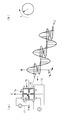
- FIG. 1 shows an example of a biomechanical physical property observation device according to the present embodiment.
- the biological tissue mechanical physical property observation device includes a pulse laser light source 1.
- An ultrashort pulse laser is used for the pulse laser light source 1.
- the ultrashort pulse laser is a femtosecond fiber laser or a femtosecond mode-locked titanium sapphire laser.
- the femtosecond fiber laser for example, an LD-pumped passive mode-locked fiber laser using a 1.55 ⁇ m band erbium (Er) -doped fiber laser as a laser gain medium is used.
- the femtosecond fiber laser may be an ytterbium (Yb) -doped fiber having a relatively wide band near 1.06 ⁇ m and a high quantum effect.
- the femtosecond fiber laser is used, for example, at a central oscillation wavelength (second harmonic output) of 780 nm, a pulse width of 120 to 75 fs (femtoseconds), an average output of 30 mW, and a repetition frequency of about 40 MHz.
- Ti: Al 2 O 3 (titanium-doped sapphire) crystal is used as a laser medium. Titanium-doped sapphire crystals are excellent in obtaining stable oscillation of femtosecond pulses.
- the femtosecond mode-locked titanium-sapphire laser is used, for example, with a central oscillation wavelength of 780 nm, a pulse width of 100 to 45 fs, an average output of 100 mW, and a repetition frequency of about 40 to 80 MHz.
- Femtosecond fiber lasers have advantages in practical aspects such as small size, light weight, simple stable operation, low cost, and low power consumption, compared to femtosecond mode-locked titanium sapphire lasers.
- the femtosecond mode-locked titanium-sapphire laser has an advantage that the spectral bandwidth is relatively wide compared to the femtosecond fiber laser, it is excellent in ultrashort pulse light oscillation, and high power oscillation is easy.
- the biological tissue mechanical property amount measuring apparatus further converts the femtosecond laser light (pulsed laser light) L 1 emitted from the pulsed laser light source 1 into the pulsed laser light L 2 for excitation and the pulsed laser light L 3 for detection.
- a beam splitter (splitting means) 2 for splitting is provided.
- the biological tissue mechanical property observation device further includes a terahertz wave generating element (radiating means) 3 for emitting pulse light including a wavelength in the far infrared wavelength range by irradiation of the pulsed laser light L 2 for excitation, and terahertz wave generation And a detection element (detection means) 4 for detecting a time-series signal of electric field intensity of transmission pulse light (or reflection pulse light) from a living tissue irradiated with pulse light from the element 3.
- Super-hemispheric silicon lenses 5 and 6 are disposed as shown in FIG. 1 on the light emission side of the terahertz wave generation element 3 and on the light incidence side of the detection element 4 respectively.
- the terahertz wave generation element 3 and the detection element 4 are photoconductive antenna (abbreviated as PCA) elements.
- the PCA element comprises a photoconductive film and an antenna electrode film.
- the photoconductive film is, for example, a thin film of gallium arsenide (abbreviated as LT-GaAs) grown at low temperature on a semi-insulating gallium arsenide (Semi-Insulating GaAs, abbreviated as SI-GaAs) substrate.
- LT-GaAs gallium arsenide
- SI-GaAs semi-insulating gallium arsenide
- the antenna electrode film is laminated on the LT-GaAs photoconductive film.
- the material of the antenna electrode film is gold (Au) or the like.
- the antenna electrode film can be formed on the LT-GaAs thin film by vapor deposition.
- FIG. 2 shows a plan view of the pattern of the antenna electrode film according to the present embodiment.
- the antenna electrode film is composed of a pair of first antenna electrode films 7 a disposed opposite to each other via a gap 8, and a pair or a plurality of pairs of second antenna electrode films 7 b disposed opposite to each other via the gap 8. .
- the gap 8 is shared by the first antenna electrode film 7a and the second antenna electrode film 7b.
- the pair of second antenna electrode films 7 b is arranged to have an angle with respect to the pair of first antenna electrode films 7 a.
- the second antenna electrode film 7 b is disposed so as to be different (substantially orthogonal) to the pair of first antenna electrode films 7 a in plan view and in substantially 90 ° orientation. That is, in the antenna electrode film, the pair of first antenna electrode films 7a and the pair of second antenna electrode films 7b have an orthogonal biaxial structure.
- the first antenna electrode film 7 a and the second antenna electrode film 7 b are each formed of the conductive transmission path 9 and the discharge electrode 10.
- the tip of the discharge electrode 10 faces the gap 8.
- the pattern of the antenna electrode film can be appropriately determined according to the frequency band of the terahertz wave to be emitted.
- the outer channel spacing d 1 of the conductive transmission line 9 is 30 [mu] m, the gap d 2 of the discharge electrode 10 facing to the 3 ⁇ m, respectively.
- a first lead 11 is connected to the conductive transmission path 9 of the first antenna electrode film 7a so that a voltage can be applied to the pair of first antenna electrode films 7a.
- a second lead 12 is connected to the conductive transmission path 9 of the second antenna electrode film 7 b so that a voltage can be applied to the pair of second antenna electrode films 7 b.
- the other ends of the first lead and the second lead are connected to the modulation means 13 shown in FIG.
- the modulation means 13 has a voltage generator (voltage generator) capable of independently applying a bias voltage to the first antenna electrode film 7a and the second antenna electrode film 7b.
- the modulation means 13 can receive the signal from the control means 14 and modulate the phase, amplitude and repetition frequency.
- a holding means 15 for holding a living tissue includes living tissue such as cartilage tissue and regenerated tissue such as regenerated cartilage.
- an optical delay means 16 for adjusting the time origin and an optical delay means 17 for measuring a time series signal are arranged.
- the arrangement order of the optical delay means 16 for time origin adjustment and the optical delay means 17 for time series signal measurement may be reversed.
- Each optical delay means 16, 17 comprises two corner cube mirrors 18 respectively.
- the corner cube mirror 18 is fixed to a one-axis drive automatic feed stage, and the stage feed changes the optical path length from the beam splitter 2 to the detection element 4 stepwise (or continuously).
- the movement of the stage can be measured by the He-Ne laser 19.
- the optical delaying means 16 and 17 of the above-mentioned configuration are characterized in that the optical path length can be changed twice as much as scanning of the corner cube mirror as compared with the case of one corner cube mirror. Therefore, there is an effect that setting for quick time origin adjustment and time series signal measurement becomes possible.
- a drive unit (trigger generation circuit) 20 for automatically scanning is connected to the optical delay means 16 for time origin adjustment and the optical delay means 17 for time series signal measurement, and this drive unit 20 is automatically controlled. Control means 14 are connected.
- An elliptical mirror (aspheric mirror) 21 and a plane mirror 22 are installed as optical elements in the incident side light path between the terahertz wave generating element 3 and the holding means 15.
- the elliptical mirror 21 condenses the pulsed light from the terahertz wave generating element 3.
- the plane mirror 22 is disposed between the optical paths of the terahertz wave generating element 3 and the elliptic mirror 21 and functions to turn back the pulsed light from the terahertz wave generating element 3.
- the number of the elliptical mirror 21 and the flat mirror 22 may be one each as in the present embodiment, but a plurality of the elliptical mirror 21 and the flat mirror 22 may be used in combination.
- an elliptical mirror (aspheric mirror) 23 and a plane mirror 24 are installed as optical elements.
- the elliptical mirror 23 condenses the transmitted pulsed light from the sample.
- the plane mirror 24 is disposed between the optical paths of the elliptical mirror 23 and the detection element 4 and functions to fold back the transmitted pulse light from the elliptical mirror 23.
- the elliptical mirror 23 and the plane mirror 24 may be one by one as in the present embodiment, or may be used in combination.
- AVC current-voltage conversion means
- the control means 14 is connected to the modulation means 13 and the current-voltage conversion means 25 directly and via the lock-in amplifier 26.
- the control means 14 can control the application of the voltage to the antenna electrode film by the modulation means 13.
- the control means 14 includes an A / D converter 14a, an information processing unit 14b, and an input / output unit 14c.
- the information processing unit 14 b includes, for example, a central processing unit (CPU), a random access memory (RAM), a read only memory (ROM), a computer readable storage medium, and the like. Then, a series of processes for realizing various functions are stored in the form of a program, for example, in a storage medium or the like in the form of a program, and the CPU reads this program into a RAM or the like to execute information processing and arithmetic processing. Thus, various functions are realized.
- the program may be installed in advance in a ROM or other storage medium, may be provided as stored in a computer-readable storage medium, or may be distributed via a wired or wireless communication means. Etc. may be applied.
- the computer readable storage medium is a magnetic disk, a magneto-optical disk, a CD-ROM, a DVD-ROM, a semiconductor memory or the like.
- Pulsed laser light L 1 from the pulsed laser light source 1 is radiated, the excitation pulse laser beam by the beam splitter 2 (pump pulse light) L 2 and the detection pulsed laser light (sampling pulsed light) is split into a L 3.
- the excitation pulse laser light L 2 is irradiated to the terahertz wave generation element 3 through the lens 27. Excitation pulsed laser light L 2 at this time is focused on the photoconductive film in the gap 8 of the antenna electrode film. In the state where the bias voltage is applied to the antenna electrode film, when the excitation pulse laser light L 2 is irradiated on the photoconductive film, the current by the light excitation flows instantaneously and the far infrared electromagnetic wave pulse (pulse light) is emitted .
- the modulation means 13 applies a bias voltage having the same amplitude and period simultaneously and with a phase shift to the first antenna electrode film 7a and the second antenna electrode film 7b in response to a command from the information processing unit 14b. Is modulated to circularly polarized light (see (a) and (b) in FIG. 3).
- the pulse light is guided to the elliptical mirror 21 after being folded back its optical path by the plane mirror 22 and collected to be irradiated to the sample.
- Transmitted pulsed light (or reflected pulsed light reflected by the sample) including optical information of the sample and transmitted through the sample is reflected by the elliptical mirror 23 and is then folded back by the plane mirror 24 and further guided to the detection element 4 Be done. At this time, the reflected or transmitted pulsed light is condensed on the photoconductive film in the gap 8 of the antenna electrode film.
- Beam splitter 2 detection pulse laser beam L 3 divided by the delay time difference by a predetermined time interval by the optical delay means 16 and the time-series signal optical delay means 17 for measuring for time origin adjustment is applied, The light is guided to the detection element 4. Detection pulsed laser light L 3 at this time is focused on the photoconductive film in the gap 8 of the antenna electrode film, which overlaps with the reflected or transmitted pulsed light of the sample.
- the detecting element 4 Only at the moment of the detection pulse laser beam L 3 is irradiated onto the photoconductive layer, the detecting element 4 is conductive. Therefore, the trigger is applied, and the electric field strength and the phase lead of the reflected or transmitted pulsed light from the sample which arrives at the moment of becoming conductive is detected as a current signal.
- the current signal detected by the detection element 4 is converted into a voltage signal by the current-voltage conversion means 25 and amplified and passed to the lock-in amplifier 26.
- the pulse light emitted from the terahertz wave generation element 3 is modulated by the modulation means 13, and the lock-in amplifier 26 uses the repetition frequency of the modulated pulse light as a reference signal, and only the voltage synchronized with the reference signal is a frequency. The signal is picked up with a filter and the influence of background noise is reduced.
- the voltage signal amplified by the lock-in amplifier 26 is converted to a digital signal by the A / D converter 14a.
- the information processing unit 14 b Fourier-transforms the digital signal to calculate the spectrum of the amplitude and phase of the electric field intensity of the reflected or transmitted pulsed light of the sample.
- the control means 14 can obtain a polarization spectrum by normalizing or subtracting the obtained spectrum with the spectrum when there is no sample.
- the control means 14 obtains the difference between the left and right polarizations of the obtained spectrum, thereby obtaining a vibrational circular dichroism spectrum (VCD spectrum: Vibrational Circular Dichroism Spectrum).
- VCD spectrum Vibrational Circular Dichroism Spectrum
- the control means 14 can obtain mechanical physical quantities of the sample based on the obtained polarization spectrum and vibrational circular dichroism spectrum, and can observe this.
- the mechanical physical quantities include elastic modulus ((), dielectric constant ( ⁇ ), relaxation time (T1), refractive index and the like.
- the terahertz wave generating element 3 is rotated. It is also possible to emit pulsed light having an arbitrary polarization plane without disposing the polarization element in the light path. Therefore, it is possible to realize polarization of pulsed light with a simple configuration without loss of pulsed light.
- the modulation means 13 can modulate pulse light by electronic control by the control means 14, the degree of freedom of the polarization pattern is high.
- pulse laser light source 2 beam splitter (splitting means) 3 Terahertz wave generator (radiation means) 4 Detection element (detection means) 5, 6 super hemispherical silicon lens 7a first antenna electrode film 7b second antenna electrode film 8 gap 9 conductive transmission path 10 discharge electrode 11 first lead 12 second lead 13 modulation means 14 control means 14a A / D converter 14b information processing unit 14c input / output unit 15 holding means 16 optical delay means 17 (for time origin adjustment) optical delay means 18 (for time series signal measurement) 18 corner cube mirror 19 He-Ne laser 20 driving device (trigger Generation circuit) 21, 23 Elliptical mirror (aspheric mirror) 22, 24 flat mirror 25 current voltage conversion means 26 lock in amplifier 27 lens
Landscapes
- Health & Medical Sciences (AREA)
- Life Sciences & Earth Sciences (AREA)
- Physics & Mathematics (AREA)
- Engineering & Computer Science (AREA)
- Chemical & Material Sciences (AREA)
- General Health & Medical Sciences (AREA)
- Biomedical Technology (AREA)
- Analytical Chemistry (AREA)
- General Physics & Mathematics (AREA)
- Immunology (AREA)
- Pathology (AREA)
- Biochemistry (AREA)
- Spectroscopy & Molecular Physics (AREA)
- Transplantation (AREA)
- Orthopedic Medicine & Surgery (AREA)
- Public Health (AREA)
- Oral & Maxillofacial Surgery (AREA)
- Veterinary Medicine (AREA)
- Animal Behavior & Ethology (AREA)
- Urology & Nephrology (AREA)
- Molecular Biology (AREA)
- Medicinal Chemistry (AREA)
- Heart & Thoracic Surgery (AREA)
- Cardiology (AREA)
- Vascular Medicine (AREA)
- Optics & Photonics (AREA)
- Food Science & Technology (AREA)
- Toxicology (AREA)
- Biophysics (AREA)
- Hematology (AREA)
- Rehabilitation Therapy (AREA)
- Rheumatology (AREA)
- Chemical Kinetics & Catalysis (AREA)
- Epidemiology (AREA)
- Botany (AREA)
- Zoology (AREA)
- Dermatology (AREA)
- Physical Education & Sports Medicine (AREA)
- Investigating Or Analysing Materials By Optical Means (AREA)
Abstract
Description
パルスレーザ光源1から放射されたパルスレーザ光L1は、ビームスプリッタ2によって励起用パルスレーザ光(ポンプパルス光)L2と検出用パルスレーザ光(サンプリングパルス光)L3とに分割される。
2 ビームスプリッタ(分割手段)
3 テラヘルツ波発生素子(放射手段)
4 検出素子(検出手段)
5,6 超半球シリコンレンズ
7a 第1アンテナ電極膜
7b 第2アンテナ電極膜
8 間隙
9 伝導性伝送路
10 放電用電極
11 第1リード
12 第2リード
13 変調手段
14 制御手段
14a A/D変換器
14b 情報処理部
14c 入出力部
15 保持手段
16 (時間原点調整用の)光学的遅延手段
17 (時系列信号測定用の)光学的遅延手段
18 コーナーキューブ鏡
19 He-Neレーザ
20 駆動装置(トリガー発生回路)
21,23 楕円鏡(非球面鏡)
22,24 平面鏡
25 電流電圧変換手段
26 ロックインアンプ
27 レンズ
Claims (3)
- 遠赤外波長域の波長を含むパルス光を用い、振動光学活性分光法により生体組織の力学的物性量を観測する生体組織力学的物性量観測方法。
- パルス励起光を受けて光キャリアを生成する光伝導膜と、
前記光伝導膜上に形成され、間隙を介して対向する一対の第1アンテナ電極膜と、
前記間隙を介して対向配置され、且つ前記第1アンテナ電極膜に対して角度を有して配置された一対または複数対の第2アンテナ電極膜と、
を有し、パルスレーザ光照射により遠赤外波長域の波長を含むパルス光を放射する放射手段を用い、
前記第1アンテナ電極膜および前記第2アンテナ電極膜へ同時に且つ位相をずらして電圧を印加し、前記パルス光を左右の円偏光に変調し、
前記円偏光を前記生体組織に照射し、
前記生体組織で反射した反射パルス光または前記生体組織を透過した透過パルス光の時系列信号を電流信号として検出し、
前記電流信号を電圧信号に変換し、
前記第1アンテナ電極膜および前記第2アンテナ電極膜へ印加した電圧周波数と同一周波数の参照信号を同期し、前記電圧信号を取り出し、
前記電圧信号を変換して得た振動円二色性スペクトルおよび/または偏光分光スペクトルをもとに前記生体組織の前記力学的物性量を観測する請求項1に記載の生体組織力学的物性量観測方法。 - 励起用パルスレーザ光を受けて光キャリアを生成する光伝導膜と前記光伝導膜上に形成されたアンテナ電極膜を備え、前記励起用パルスレーザ光の照射により遠赤外波長域の波長を含むパルス光を放射する放射手段と、
前記アンテナ電極膜に印加する電圧を発生させる電圧発生部を有し、前記放射手段から放射されるパルス光を左右の円偏光に変調する変調手段と、
生体組織が保持される保持手段と、
光伝導膜とアンテナ電極膜を備え、前記生体組織で反射した反射パルス光または前記生体組織を透過した透過パルス光の時系列信号を受けて電流信号を出力する検出手段と、
前記電流信号を電圧信号に変換する電流電圧変換手段と、
前記変調手段の電圧周波数と同一周波数の参照信号を同期し、前記電圧信号を取り出すロックインアンプと、
前記パルス光の変調を制御する制御手段と、
を備え、
前記アンテナ電極膜が、間隙を介して対向する一対の第1アンテナ電極膜と、前記間隙を介して対向配置され、且つ前記第1アンテナ電極膜に対して角度を有して配置された一対または複数対の第2アンテナ電極膜と、
を有し、
前記制御手段が、前記第1アンテナ電極膜および第2アンテナ電極膜に対して、それぞれ独立に電圧を印加するよう前記変調手段を制御する機能を有する生体組織力学的物性量観測装置。
Priority Applications (3)
| Application Number | Priority Date | Filing Date | Title |
|---|---|---|---|
| US16/091,531 US10718708B2 (en) | 2016-04-05 | 2017-04-04 | Method for observing dynamic physical property of biological tissue and device for observing dynamic physical property of biological tissue |
| EP17779148.0A EP3441748A4 (en) | 2016-04-05 | 2017-04-04 | METHOD FOR OBSERVING THE DYNAMIC PHYSICAL PROPERTIES OF BIOLOGICAL TISSUE AND DEVICE FOR OBSERVING THE DYNAMIC PHYSICAL PROPERTIES OF BIOLOGICAL TISSUE |
| JP2018510620A JP7078956B2 (ja) | 2016-04-05 | 2017-04-04 | 生体組織力学的物性量観測方法および生体組織力学的物性量観測装置 |
Applications Claiming Priority (2)
| Application Number | Priority Date | Filing Date | Title |
|---|---|---|---|
| JP2016-075571 | 2016-04-05 | ||
| JP2016075571 | 2016-04-05 |
Publications (1)
| Publication Number | Publication Date |
|---|---|
| WO2017175770A1 true WO2017175770A1 (ja) | 2017-10-12 |
Family
ID=60000479
Family Applications (1)
| Application Number | Title | Priority Date | Filing Date |
|---|---|---|---|
| PCT/JP2017/014142 Ceased WO2017175770A1 (ja) | 2016-04-05 | 2017-04-04 | 生体組織力学的物性量観測方法および生体組織力学的物性量観測装置 |
Country Status (4)
| Country | Link |
|---|---|
| US (1) | US10718708B2 (ja) |
| EP (1) | EP3441748A4 (ja) |
| JP (1) | JP7078956B2 (ja) |
| WO (1) | WO2017175770A1 (ja) |
Cited By (2)
| Publication number | Priority date | Publication date | Assignee | Title |
|---|---|---|---|---|
| WO2021070428A1 (ja) * | 2019-10-09 | 2021-04-15 | パナソニックIpマネジメント株式会社 | 撮影装置 |
| JPWO2022181320A1 (ja) * | 2021-02-25 | 2022-09-01 |
Families Citing this family (3)
| Publication number | Priority date | Publication date | Assignee | Title |
|---|---|---|---|---|
| EP3441748A4 (en) | 2016-04-05 | 2019-12-18 | Advanced Bio-Spectroscopy Co., Ltd. | METHOD FOR OBSERVING THE DYNAMIC PHYSICAL PROPERTIES OF BIOLOGICAL TISSUE AND DEVICE FOR OBSERVING THE DYNAMIC PHYSICAL PROPERTIES OF BIOLOGICAL TISSUE |
| CN108627546B (zh) * | 2018-04-16 | 2021-04-02 | 北京工业大学 | 一种纳米多层膜调制比的实时测量方法及装置 |
| GB2592015B (en) | 2020-02-11 | 2022-02-23 | Irsweep Ag | Vibrational circular dichroism spectroscopy |
Citations (3)
| Publication number | Priority date | Publication date | Assignee | Title |
|---|---|---|---|---|
| JP2006098294A (ja) * | 2004-09-30 | 2006-04-13 | Japan Science & Technology Agency | 赤外光放射装置および時系列変換パルス分光計測装置ならびに赤外光放射方法 |
| US20070222988A1 (en) * | 2006-03-21 | 2007-09-27 | Eric Jiang | Vibrational circular dichroism spectrometer using reflective optics |
| JP2012202812A (ja) * | 2011-03-25 | 2012-10-22 | Jasco Corp | 円二色性測定装置及び円二色性測定方法 |
Family Cites Families (18)
| Publication number | Priority date | Publication date | Assignee | Title |
|---|---|---|---|---|
| JP2000275103A (ja) | 1999-03-25 | 2000-10-06 | Jasco Corp | 時系列変換赤外分光装置 |
| JP4237363B2 (ja) | 1999-11-10 | 2009-03-11 | 日本分光株式会社 | 赤外分光装置 |
| JP2002277394A (ja) | 2001-03-15 | 2002-09-25 | Mitsuo Takeda | 誘電体物質の光物性定数の光学的測定方法及びその装置並びにその装置を組み込んだ製造システム |
| JP2003279412A (ja) | 2002-03-22 | 2003-10-02 | Nippon Spectral Kenkyusho:Kk | 単色パルス光励起によってフォトニック結晶部材から放射された白色電磁波を光源とする分光測定装置 |
| JP3851242B2 (ja) | 2002-07-29 | 2006-11-29 | 松下電器産業株式会社 | 無電極ランプ及び無電極ランプ用の発光バルブの製造方法 |
| JP3806742B2 (ja) | 2003-06-30 | 2006-08-09 | 独立行政法人科学技術振興機構 | 光伝導素子及びそれを用いた赤外放射素子並びにその検出素子 |
| JP2005069840A (ja) | 2003-08-22 | 2005-03-17 | Japan Science & Technology Agency | 時系列変換パルス分光計測装置の時系列信号取得のための光路差補償機構 |
| JP3830483B2 (ja) | 2003-10-17 | 2006-10-04 | 独立行政法人科学技術振興機構 | 反射分光スペクトル観測のための光学配置 |
| JP3914553B2 (ja) | 2004-09-29 | 2007-05-16 | 独立行政法人科学技術振興機構 | 時系列微弱信号の検出が可能な時系列変換パルス分光計測装置及びその方法 |
| JP4294566B2 (ja) | 2004-09-30 | 2009-07-15 | 独立行政法人科学技術振興機構 | 全反射吸収測定用プリズムを用いた全反射吸収測定方法 |
| JP3922463B2 (ja) | 2004-09-30 | 2007-05-30 | 独立行政法人科学技術振興機構 | 赤外光放射装置および赤外光検出装置ならびに時系列変換パルス分光計測装置 |
| WO2006035780A1 (ja) | 2004-09-30 | 2006-04-06 | Japan Science And Technology Agency | 赤外光放射装置、赤外光検出装置および時系列変換パルス分光計測装置ならびに赤外光放射方法 |
| JP2010223586A (ja) | 2009-03-19 | 2010-10-07 | Seiko Epson Corp | テラヘルツ分光測定装置およびテラヘルツ分光測定方法 |
| US8456629B2 (en) * | 2009-11-18 | 2013-06-04 | The Regents Of The University Of California | Apparatus and method for multiple-pulse impulsive stimulated raman spectroscopy |
| JP2011112548A (ja) | 2009-11-27 | 2011-06-09 | Sony Corp | 生体サンプル解析方法、生体サンプル解析装置及び生体サンプル解析プログラム |
| JP2014209094A (ja) | 2013-03-29 | 2014-11-06 | キヤノン株式会社 | テラヘルツ波を用いて試料の情報を取得する情報取得装置および情報取得方法 |
| JP6245600B2 (ja) * | 2013-08-30 | 2017-12-13 | 国立研究開発法人物質・材料研究機構 | 偏光感受性テラヘルツ波検出器 |
| EP3441748A4 (en) | 2016-04-05 | 2019-12-18 | Advanced Bio-Spectroscopy Co., Ltd. | METHOD FOR OBSERVING THE DYNAMIC PHYSICAL PROPERTIES OF BIOLOGICAL TISSUE AND DEVICE FOR OBSERVING THE DYNAMIC PHYSICAL PROPERTIES OF BIOLOGICAL TISSUE |
-
2017
- 2017-04-04 EP EP17779148.0A patent/EP3441748A4/en not_active Withdrawn
- 2017-04-04 JP JP2018510620A patent/JP7078956B2/ja active Active
- 2017-04-04 WO PCT/JP2017/014142 patent/WO2017175770A1/ja not_active Ceased
- 2017-04-04 US US16/091,531 patent/US10718708B2/en active Active
Patent Citations (3)
| Publication number | Priority date | Publication date | Assignee | Title |
|---|---|---|---|---|
| JP2006098294A (ja) * | 2004-09-30 | 2006-04-13 | Japan Science & Technology Agency | 赤外光放射装置および時系列変換パルス分光計測装置ならびに赤外光放射方法 |
| US20070222988A1 (en) * | 2006-03-21 | 2007-09-27 | Eric Jiang | Vibrational circular dichroism spectrometer using reflective optics |
| JP2012202812A (ja) * | 2011-03-25 | 2012-10-22 | Jasco Corp | 円二色性測定装置及び円二色性測定方法 |
Non-Patent Citations (3)
| Title |
|---|
| HIROAKI MINAMIDE ET AL.: "A Continuously Tunable Ring-Cavity THz-Wave Parametric Oscillator", THE REVIEW OF LASER ENGINEERING, vol. 29, no. 11, November 2001 (2001-11-01), pages 744 - 748, XP055429564 * |
| See also references of EP3441748A4 * |
| TAKASHI NOTAKE ET AL.: "Hacho Kahen Terahertz- ha Kogen o Mochiita Bunko Stokes Henko Keisoku System no Kaihatsu", EXTENDED ABSTRACTS, JAPAN SOCIETY OF APPLIED PHYSICS AND RELATED SOCIETIES, 2012, pages 04 - 201, XP9514968 * |
Cited By (6)
| Publication number | Priority date | Publication date | Assignee | Title |
|---|---|---|---|---|
| WO2021070428A1 (ja) * | 2019-10-09 | 2021-04-15 | パナソニックIpマネジメント株式会社 | 撮影装置 |
| CN114402191A (zh) * | 2019-10-09 | 2022-04-26 | 松下知识产权经营株式会社 | 摄影装置 |
| US12279026B2 (en) | 2019-10-09 | 2025-04-15 | Panasonic Intellectual Property Management Co., Ltd. | Imaging device |
| JPWO2022181320A1 (ja) * | 2021-02-25 | 2022-09-01 | ||
| WO2022181320A1 (ja) * | 2021-02-25 | 2022-09-01 | 大学共同利用機関法人自然科学研究機構 | 円偏光照射器、分析装置及び顕微鏡 |
| JP7749245B2 (ja) | 2021-02-25 | 2025-10-06 | 大学共同利用機関法人自然科学研究機構 | 円偏光照射器、分析装置及び顕微鏡 |
Also Published As
| Publication number | Publication date |
|---|---|
| US20190128803A1 (en) | 2019-05-02 |
| EP3441748A1 (en) | 2019-02-13 |
| JPWO2017175770A1 (ja) | 2019-06-27 |
| JP7078956B2 (ja) | 2022-06-01 |
| EP3441748A4 (en) | 2019-12-18 |
| US10718708B2 (en) | 2020-07-21 |
Similar Documents
| Publication | Publication Date | Title |
|---|---|---|
| JP7078956B2 (ja) | 生体組織力学的物性量観測方法および生体組織力学的物性量観測装置 | |
| US20250123147A1 (en) | Systems and methods for stimulated brillouin microscopy | |
| US9835840B2 (en) | Methods for optical amplified imaging using a two-dimensional spectral brush | |
| US6466806B1 (en) | Photoacoustic material analysis | |
| JP6386655B2 (ja) | テラヘルツ波発生装置及びそれを用いた分光装置 | |
| JP6692103B2 (ja) | テラヘルツ画像の高コントラスト/準リアルタイム取得用のシステム及び方法 | |
| JP7478479B2 (ja) | 光検出装置、および光検出方法 | |
| CN110132851B (zh) | 一种基于飞秒单脉冲干涉的瞬时二维光声波测量方法 | |
| US20140328365A1 (en) | Multifunctional laser device | |
| CN113552071A (zh) | 一种光声成像系统 | |
| JP2015158482A (ja) | 誘導ラマン散乱計測装置 | |
| CN104483289A (zh) | 基于扫频光学相干层析技术的双折射率检测装置及其方法 | |
| JP6799295B2 (ja) | 生体組織力学的物性量観測方法および生体組織力学的物性量観測装置 | |
| WO2023243052A1 (ja) | 光源 | |
| Lock et al. | Vibrational relaxation and coupling of two OH-stretch oscillators with an intramolecular hydrogen bond | |
| Lang et al. | Technology and applications of ultrafast fiber lasers | |
| TWI467169B (zh) | 利用脈衝雷射光源產生的聲學信號之造影系統 | |
| Chen et al. | Pulse-to-Pulse Wavelength Switching Near-infrared Fiber Laser for Multi-contrast PA Imaging | |
| Buccheri et al. | Spatial and spectral properties of small area THz generation for sub-wavelength microscopy | |
| Wu et al. | Tailoring Frequency Response of Fiber Laser Ultrasound Sensors via Delayed Self-Heterodyne Demodulation for versatile Photoacoustic Imaging | |
| Samolis et al. | Mid-infrared Photothermal Imaging of Fibroblast Cells | |
| Sulatsky et al. | Analysis of spectral characteristics of the human cornea obtained in the terahertz frequency range | |
| WO2025243411A1 (ja) | 2波数帯域用光源 | |
| Dasa et al. | High pulse energy supercontinuum laser for spectroscopic photoacoustic imaging of lipids in the 1650-1850 nm window | |
| Kao | The use of advanced light source and signal processing in scanning optical microscopy |
Legal Events
| Date | Code | Title | Description |
|---|---|---|---|
| ENP | Entry into the national phase |
Ref document number: 2018510620 Country of ref document: JP Kind code of ref document: A |
|
| NENP | Non-entry into the national phase |
Ref country code: DE |
|
| WWE | Wipo information: entry into national phase |
Ref document number: 2017779148 Country of ref document: EP |
|
| ENP | Entry into the national phase |
Ref document number: 2017779148 Country of ref document: EP Effective date: 20181105 |
|
| 121 | Ep: the epo has been informed by wipo that ep was designated in this application |
Ref document number: 17779148 Country of ref document: EP Kind code of ref document: A1 |