WO2017175978A1 - 양극활물질, 그 제조 방법, 및 이를 포함하는 리튬이차전지 - Google Patents
양극활물질, 그 제조 방법, 및 이를 포함하는 리튬이차전지 Download PDFInfo
- Publication number
- WO2017175978A1 WO2017175978A1 PCT/KR2017/002697 KR2017002697W WO2017175978A1 WO 2017175978 A1 WO2017175978 A1 WO 2017175978A1 KR 2017002697 W KR2017002697 W KR 2017002697W WO 2017175978 A1 WO2017175978 A1 WO 2017175978A1
- Authority
- WO
- WIPO (PCT)
- Prior art keywords
- active material
- positive electrode
- electrode active
- crystal structure
- cathode active
- Prior art date
- Legal status (The legal status is an assumption and is not a legal conclusion. Google has not performed a legal analysis and makes no representation as to the accuracy of the status listed.)
- Ceased
Links
Images












Classifications
-
- H—ELECTRICITY
- H01—ELECTRIC ELEMENTS
- H01M—PROCESSES OR MEANS, e.g. BATTERIES, FOR THE DIRECT CONVERSION OF CHEMICAL ENERGY INTO ELECTRICAL ENERGY
- H01M4/00—Electrodes
- H01M4/02—Electrodes composed of, or comprising, active material
- H01M4/36—Selection of substances as active materials, active masses, active liquids
- H01M4/48—Selection of substances as active materials, active masses, active liquids of inorganic oxides or hydroxides
- H01M4/52—Selection of substances as active materials, active masses, active liquids of inorganic oxides or hydroxides of nickel, cobalt or iron
- H01M4/525—Selection of substances as active materials, active masses, active liquids of inorganic oxides or hydroxides of nickel, cobalt or iron of mixed oxides or hydroxides containing iron, cobalt or nickel for inserting or intercalating light metals, e.g. LiNiO2, LiCoO2 or LiCoOxFy
-
- C—CHEMISTRY; METALLURGY
- C01—INORGANIC CHEMISTRY
- C01G—COMPOUNDS CONTAINING METALS NOT COVERED BY SUBCLASSES C01D OR C01F
- C01G41/00—Compounds of tungsten
- C01G41/02—Oxides; Hydroxides
-
- C—CHEMISTRY; METALLURGY
- C01—INORGANIC CHEMISTRY
- C01G—COMPOUNDS CONTAINING METALS NOT COVERED BY SUBCLASSES C01D OR C01F
- C01G53/00—Compounds of nickel
- C01G53/40—Complex oxides containing nickel and at least one other metal element
- C01G53/42—Complex oxides containing nickel and at least one other metal element containing alkali metals, e.g. LiNiO2
-
- C—CHEMISTRY; METALLURGY
- C01—INORGANIC CHEMISTRY
- C01G—COMPOUNDS CONTAINING METALS NOT COVERED BY SUBCLASSES C01D OR C01F
- C01G53/00—Compounds of nickel
- C01G53/40—Complex oxides containing nickel and at least one other metal element
- C01G53/42—Complex oxides containing nickel and at least one other metal element containing alkali metals, e.g. LiNiO2
- C01G53/44—Complex oxides containing nickel and at least one other metal element containing alkali metals, e.g. LiNiO2 containing manganese
- C01G53/50—Complex oxides containing nickel and at least one other metal element containing alkali metals, e.g. LiNiO2 containing manganese of the type (MnO2)n-, e.g. Li(NixMn1-x)O2 or Li(MyNixMn1-x-y)O2
- C01G53/502—Complex oxides containing nickel and at least one other metal element containing alkali metals, e.g. LiNiO2 containing manganese of the type (MnO2)n-, e.g. Li(NixMn1-x)O2 or Li(MyNixMn1-x-y)O2 containing lithium and cobalt
- C01G53/504—Complex oxides containing nickel and at least one other metal element containing alkali metals, e.g. LiNiO2 containing manganese of the type (MnO2)n-, e.g. Li(NixMn1-x)O2 or Li(MyNixMn1-x-y)O2 containing lithium and cobalt with the molar ratio of nickel with respect to all the metals other than alkali metals higher than or equal to 0.5, e.g. Li(MzNixCoyMn1-x-y-z)O2 with x ≥ 0.5
-
- C—CHEMISTRY; METALLURGY
- C01—INORGANIC CHEMISTRY
- C01G—COMPOUNDS CONTAINING METALS NOT COVERED BY SUBCLASSES C01D OR C01F
- C01G53/00—Compounds of nickel
- C01G53/80—Compounds containing nickel, with or without oxygen or hydrogen, and containing one or more other elements
- C01G53/82—Compounds containing nickel, with or without oxygen or hydrogen, and containing two or more other elements
-
- H—ELECTRICITY
- H01—ELECTRIC ELEMENTS
- H01M—PROCESSES OR MEANS, e.g. BATTERIES, FOR THE DIRECT CONVERSION OF CHEMICAL ENERGY INTO ELECTRICAL ENERGY
- H01M10/00—Secondary cells; Manufacture thereof
- H01M10/05—Accumulators with non-aqueous electrolyte
- H01M10/052—Li-accumulators
-
- H—ELECTRICITY
- H01—ELECTRIC ELEMENTS
- H01M—PROCESSES OR MEANS, e.g. BATTERIES, FOR THE DIRECT CONVERSION OF CHEMICAL ENERGY INTO ELECTRICAL ENERGY
- H01M4/00—Electrodes
- H01M4/02—Electrodes composed of, or comprising, active material
- H01M4/36—Selection of substances as active materials, active masses, active liquids
- H01M4/362—Composites
- H01M4/366—Composites as layered products
-
- H—ELECTRICITY
- H01—ELECTRIC ELEMENTS
- H01M—PROCESSES OR MEANS, e.g. BATTERIES, FOR THE DIRECT CONVERSION OF CHEMICAL ENERGY INTO ELECTRICAL ENERGY
- H01M4/00—Electrodes
- H01M4/02—Electrodes composed of, or comprising, active material
- H01M4/36—Selection of substances as active materials, active masses, active liquids
- H01M4/48—Selection of substances as active materials, active masses, active liquids of inorganic oxides or hydroxides
- H01M4/485—Selection of substances as active materials, active masses, active liquids of inorganic oxides or hydroxides of mixed oxides or hydroxides for inserting or intercalating light metals, e.g. LiTi2O4 or LiTi2OxFy
-
- H—ELECTRICITY
- H01—ELECTRIC ELEMENTS
- H01M—PROCESSES OR MEANS, e.g. BATTERIES, FOR THE DIRECT CONVERSION OF CHEMICAL ENERGY INTO ELECTRICAL ENERGY
- H01M4/00—Electrodes
- H01M4/02—Electrodes composed of, or comprising, active material
- H01M4/36—Selection of substances as active materials, active masses, active liquids
- H01M4/48—Selection of substances as active materials, active masses, active liquids of inorganic oxides or hydroxides
- H01M4/50—Selection of substances as active materials, active masses, active liquids of inorganic oxides or hydroxides of manganese
- H01M4/505—Selection of substances as active materials, active masses, active liquids of inorganic oxides or hydroxides of manganese of mixed oxides or hydroxides containing manganese for inserting or intercalating light metals, e.g. LiMn2O4 or LiMn2OxFy
-
- H—ELECTRICITY
- H01—ELECTRIC ELEMENTS
- H01M—PROCESSES OR MEANS, e.g. BATTERIES, FOR THE DIRECT CONVERSION OF CHEMICAL ENERGY INTO ELECTRICAL ENERGY
- H01M4/00—Electrodes
- H01M4/02—Electrodes composed of, or comprising, active material
- H01M4/62—Selection of inactive substances as ingredients for active masses, e.g. binders, fillers
- H01M4/624—Electric conductive fillers
- H01M4/626—Metals
-
- C—CHEMISTRY; METALLURGY
- C01—INORGANIC CHEMISTRY
- C01P—INDEXING SCHEME RELATING TO STRUCTURAL AND PHYSICAL ASPECTS OF SOLID INORGANIC COMPOUNDS
- C01P2002/00—Crystal-structural characteristics
- C01P2002/50—Solid solutions
- C01P2002/52—Solid solutions containing elements as dopants
-
- C—CHEMISTRY; METALLURGY
- C01—INORGANIC CHEMISTRY
- C01P—INDEXING SCHEME RELATING TO STRUCTURAL AND PHYSICAL ASPECTS OF SOLID INORGANIC COMPOUNDS
- C01P2002/00—Crystal-structural characteristics
- C01P2002/50—Solid solutions
- C01P2002/52—Solid solutions containing elements as dopants
- C01P2002/54—Solid solutions containing elements as dopants one element only
-
- C—CHEMISTRY; METALLURGY
- C01—INORGANIC CHEMISTRY
- C01P—INDEXING SCHEME RELATING TO STRUCTURAL AND PHYSICAL ASPECTS OF SOLID INORGANIC COMPOUNDS
- C01P2002/00—Crystal-structural characteristics
- C01P2002/70—Crystal-structural characteristics defined by measured X-ray, neutron or electron diffraction data
- C01P2002/72—Crystal-structural characteristics defined by measured X-ray, neutron or electron diffraction data by d-values or two theta-values, e.g. as X-ray diagram
-
- C—CHEMISTRY; METALLURGY
- C01—INORGANIC CHEMISTRY
- C01P—INDEXING SCHEME RELATING TO STRUCTURAL AND PHYSICAL ASPECTS OF SOLID INORGANIC COMPOUNDS
- C01P2004/00—Particle morphology
- C01P2004/01—Particle morphology depicted by an image
- C01P2004/03—Particle morphology depicted by an image obtained by SEM
-
- C—CHEMISTRY; METALLURGY
- C01—INORGANIC CHEMISTRY
- C01P—INDEXING SCHEME RELATING TO STRUCTURAL AND PHYSICAL ASPECTS OF SOLID INORGANIC COMPOUNDS
- C01P2004/00—Particle morphology
- C01P2004/01—Particle morphology depicted by an image
- C01P2004/04—Particle morphology depicted by an image obtained by TEM, STEM, STM or AFM
-
- C—CHEMISTRY; METALLURGY
- C01—INORGANIC CHEMISTRY
- C01P—INDEXING SCHEME RELATING TO STRUCTURAL AND PHYSICAL ASPECTS OF SOLID INORGANIC COMPOUNDS
- C01P2004/00—Particle morphology
- C01P2004/10—Particle morphology extending in one dimension, e.g. needle-like
- C01P2004/12—Particle morphology extending in one dimension, e.g. needle-like with a cylindrical shape
-
- C—CHEMISTRY; METALLURGY
- C01—INORGANIC CHEMISTRY
- C01P—INDEXING SCHEME RELATING TO STRUCTURAL AND PHYSICAL ASPECTS OF SOLID INORGANIC COMPOUNDS
- C01P2004/00—Particle morphology
- C01P2004/30—Particle morphology extending in three dimensions
- C01P2004/45—Aggregated particles or particles with an intergrown morphology
-
- H—ELECTRICITY
- H01—ELECTRIC ELEMENTS
- H01M—PROCESSES OR MEANS, e.g. BATTERIES, FOR THE DIRECT CONVERSION OF CHEMICAL ENERGY INTO ELECTRICAL ENERGY
- H01M4/00—Electrodes
- H01M4/02—Electrodes composed of, or comprising, active material
- H01M2004/021—Physical characteristics, e.g. porosity, surface area
-
- H—ELECTRICITY
- H01—ELECTRIC ELEMENTS
- H01M—PROCESSES OR MEANS, e.g. BATTERIES, FOR THE DIRECT CONVERSION OF CHEMICAL ENERGY INTO ELECTRICAL ENERGY
- H01M4/00—Electrodes
- H01M4/02—Electrodes composed of, or comprising, active material
- H01M2004/026—Electrodes composed of, or comprising, active material characterised by the polarity
- H01M2004/028—Positive electrodes
-
- H—ELECTRICITY
- H01—ELECTRIC ELEMENTS
- H01M—PROCESSES OR MEANS, e.g. BATTERIES, FOR THE DIRECT CONVERSION OF CHEMICAL ENERGY INTO ELECTRICAL ENERGY
- H01M4/00—Electrodes
- H01M4/02—Electrodes composed of, or comprising, active material
- H01M4/04—Processes of manufacture in general
- H01M4/0471—Processes of manufacture in general involving thermal treatment, e.g. firing, sintering, backing particulate active material, thermal decomposition, pyrolysis
-
- Y—GENERAL TAGGING OF NEW TECHNOLOGICAL DEVELOPMENTS; GENERAL TAGGING OF CROSS-SECTIONAL TECHNOLOGIES SPANNING OVER SEVERAL SECTIONS OF THE IPC; TECHNICAL SUBJECTS COVERED BY FORMER USPC CROSS-REFERENCE ART COLLECTIONS [XRACs] AND DIGESTS
- Y02—TECHNOLOGIES OR APPLICATIONS FOR MITIGATION OR ADAPTATION AGAINST CLIMATE CHANGE
- Y02E—REDUCTION OF GREENHOUSE GAS [GHG] EMISSIONS, RELATED TO ENERGY GENERATION, TRANSMISSION OR DISTRIBUTION
- Y02E60/00—Enabling technologies; Technologies with a potential or indirect contribution to GHG emissions mitigation
- Y02E60/10—Energy storage using batteries
Definitions
- the present application relates to a cathode active material, a method of manufacturing the same, and a lithium secondary battery including the same.
- Korean Patent Publication No. 10-2014-0119621 Application No. 10-2013-0150315
- Ni ⁇ Mn ⁇ Co ⁇ - ⁇ A ⁇ CO3 (A is one or two or more selected from the group consisting of B, Al, Ga, Ti and In) , ⁇ is 0.05 to 0.4, ⁇ is 0.5 to 0.8, ⁇ is 0 to 0.4, and ⁇ is 0.001 to 0.1) using a precursor for preparing a lithium excess cathode active material, and the type of metal to be substituted in the precursor
- a secondary battery having a high voltage capacity and a long lifespan is disclosed by adjusting the composition and controlling the type and amount of metal added.
- One technical problem to be solved by the present application is to provide a highly reliable cathode active material, a method of manufacturing the same, and a lithium secondary battery including the same.
- Another technical problem to be solved by the present application is to provide a high capacity cathode active material, a method of manufacturing the same, and a lithium secondary battery including the same.
- Another technical problem to be solved by the present application is to provide a long-life cathode active material, a method of manufacturing the same, and a lithium secondary battery including the same.
- Another technical problem to be solved by the present application is to provide a cathode active material having improved thermal stability, a method of manufacturing the same, and a lithium secondary battery including the same.
- the present application to solve the above technical problem provides a cathode active material.
- the cathode active material may include at least one of nickel, cobalt, manganese, or aluminum, lithium, and an additive metal
- the additive metal may include nickel, cobalt, manganese, and aluminum and other elements.
- the content of the added metal may be less than 2 mol% on average.
- the additive metal may have a constant concentration throughout the particle.
- the cathode active material may include a first crystal structure and a second crystal structure having different crystal systems.
- the ratio of the first crystal structure and the second crystal structure may be adjusted according to the content of the additive metal.
- the first crystal structure is a cubic crystal structure
- the second crystal structure is a trigonal or rhombohedral crystal structure
- the first crystal structure can be increased.
- the ratio of the first crystal structure is higher than the ratio of the second crystal structure, and at the particle center, the ratio of the second crystal structure is higher than the ratio of the first crystal structure.
- the cathode active material may be represented by the following ⁇ Formula 1>.
- M1, M2, M3 is any one selected from nickel, cobalt, manganese, or aluminum, 0 ⁇ a ⁇ 1, 0 ⁇ b ⁇ 1, 0 ⁇ c ⁇ 1, 0 ⁇ d ⁇ 0.02, at least one of a, b, and c is greater than 0, and M1, M2, M3, and M4 are different metals.
- M4 is any one of tungsten, molybdenum, zirconium, niobium, tantalum, titanium, rubidium, bismuth, magnesium, zinc, gallium, vanadium, chromium, calcium, strontium, or tin. It may include.
- the crystal structure may be controlled according to the d value in ⁇ Formula 1>, and the penetration amount of fluorine may be controlled during the charge and discharge process.
- the present invention provides a method for producing a cathode active material.
- the method for producing a positive electrode active material preparing a base aqueous solution containing at least one of nickel, cobalt, manganese, or aluminum, and an additional aqueous solution containing an additive metal, the base aqueous solution and the Providing an aqueous solution to the reactor to prepare a cathode active material precursor doped with the additive metal in a metal hydroxide including at least one of nickel, cobalt, manganese, or aluminum, and preparing the cathode active material precursor and the lithium salt.
- the method may include preparing a cathode active material doped with at least one of nickel, cobalt, manganese, or aluminum and a metal oxide containing lithium at less than 2 mol%.
- the firing temperature of the cathode active material precursor and the lithium salt may be adjusted according to the doping concentration of the additive metal.
- the firing temperature of the cathode active material precursor and the lithium salt may increase.
- the doping concentration of the additive metal may be adjusted by the concentration of the additive metal in the aqueous solution.
- the pH in the reactor can be adjusted.
- Cathode active material nickel, cobalt, manganese, or at least any one of aluminum, lithium, and an additive metal, the additive metal, nickel, cobalt, manganese, and other elements other than aluminum And the content of the additional metal (eg tungsten) may be less than 2 mol% on average. Accordingly, a high reliability cathode active material having high capacity and long life and improved thermal stability can be provided.
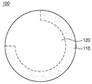
- FIG. 1 is a view for explaining a cathode active material according to an embodiment of the present invention.
- FIG. 2 is a view showing an A-B cross section of the positive electrode active material according to the embodiment of the present invention shown in FIG.
- FIG 3 is a view for explaining a cathode active material according to a modification of the embodiment of the present invention.
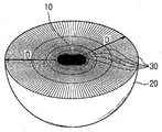
- FIG. 4 is a view for explaining the primary particles contained in the positive electrode active material according to an embodiment of the present invention.
- Example 6 is an ASTAR image of a cathode active material according to Example 7 of the present invention.
- EDS mapping data (after charging and discharging) of the cathode active material according to Example 7 of the present invention.
- Example 12 is an SEM image of a positive electrode active material according to Example 7 of the present invention.
- Example 13 is an SEM image of a positive electrode active material according to Example 10 of the present invention.
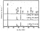
- Example 14 is XRD result data of the positive electrode active material according to Example 2, Example 7, Comparative Example 1 of the present invention.
- Example 15 is a graph measuring charge and discharge characteristics of the positive electrode active material according to Example 2, Example 7, Example 10, Example 12, and Comparative Example 1 of the present invention.
- 16 is a graph measuring capacity retention characteristics of the positive electrode active material according to Examples 2, 7, and 10, 12, and Comparative Example 1 of the present invention.
- Example 17 is a graph measuring capacity retention characteristics of the positive electrode active material according to Example 7 and Comparative Example 1 of the present invention.
- Example 19 is a graph of EIS measurement of a positive electrode active material according to Example 7 of the present invention.
- 20 to 23 are graphs measuring the differential capacity of the positive electrode active material according to Examples 2, 7, 10, and 3 and Comparative Example 1 of the present invention.
- 25 is a graph measuring capacity retention characteristics of the positive electrode active material according to Examples 1 to 4 and Comparative Example 1 of the present invention.
- 26 is a graph measuring charge and discharge characteristics of the positive electrode active material according to Examples 5 to 8 and Comparative Example 1 of the present invention.
- Example 30 is a graph measuring charge and discharge characteristics of the positive electrode active material according to Example 2, Example 7, Example 10, and Comparative Examples 1 to 5 of the present invention.
- 31 is a graph measuring capacity retention characteristics of the positive electrode active material according to Examples 2, 7, 10, and Comparative Examples 1 to 5 of the present invention.
- Example 32 is a XRD result graph of the positive electrode active material according to Example 13 of the present invention.
- 35 is a TEM photograph and SEAD pattern of the positive electrode active material according to Example 13 of the present invention.
- Example 36 is EPMA data of a cathode active material according to Example 13 of the present invention.
- Example 37 is a view showing TEM-EDX mapping of a positive electrode active material according to Example 13 of the present invention.
- Example 38 is a graph measuring charge and discharge characteristics of the positive electrode active material according to Example 13 and Comparative Example 6 of the present invention.
- Example 39 is a graph measuring capacity retention characteristics of the positive electrode active material according to Example 13 and Comparative Example 6 of the present invention.
- FIG. 41 is an SEM image of a cathode active material precursor according to Example 14 of the present invention.
- Example 43 is an SEM image of a cathode active material according to Example 14 of the present invention .
- Example 44 is a graph measuring charge and discharge characteristics of the positive electrode active material according to Example 14 and Comparative Example 7 of the present invention.
- Example 45 is a graph measuring capacity retention characteristics of the positive electrode active material according to Example 14 and Comparative Example 7 of the present invention.
- Example 46 is a graph of XRD results of a cathode active material according to Example 15 and Comparative Example 8 of the present invention.
- Example 47 is a graph measuring charge and discharge characteristics of the positive electrode active material according to Example 15 and Comparative Example 8 of the present invention.
- FIG. 48 is a graph measuring capacity retention characteristics of the positive electrode active material according to Example 15 and Comparative Example 8.
- FIG. 48 is a graph measuring capacity retention characteristics of the positive electrode active material according to Example 15 and Comparative Example 8.
- Example 49 is a graph showing the XRD results of the positive electrode active material according to Example 16 and Comparative Example 9 of the present invention.
- Example 50 is a graph measuring charge and discharge characteristics of the positive electrode active material according to Example 16 and Comparative Example 9 of the present invention.
- FIG. 51 is a graph measuring capacity retention characteristics of the positive electrode active material according to Example 16 and Comparative Example 9.
- FIG. 51 is a graph measuring capacity retention characteristics of the positive electrode active material according to Example 16 and Comparative Example 9.
- Example 52 is a graph illustrating charge and discharge characteristics of the cathode active material according to Example 17 and Comparative Example 1 of the present invention.
- FIG. 53 is a graph measuring capacity retention characteristics of the positive electrode active material according to Example 17 and Comparative Example 1.
- FIG. 53 is a graph measuring capacity retention characteristics of the positive electrode active material according to Example 17 and Comparative Example 1.
- Example 54 is a graph illustrating charge and discharge characteristics of the cathode active material according to Example 18 and Comparative Example 1 of the present invention.
- FIG. 55 is a graph measuring capacity retention characteristics of the positive electrode active material according to Example 18 and Comparative Example 1.
- FIG. 55 is a graph measuring capacity retention characteristics of the positive electrode active material according to Example 18 and Comparative Example 1.
- Example 56 is a graph measuring charge and discharge characteristics of the positive electrode active material according to Example 19 and Comparative Example 1 of the present invention.
- FIG. 57 is a graph measuring capacity retention characteristics of the positive electrode active material according to Example 19 and Comparative Example 1.
- FIG. 57 is a graph measuring capacity retention characteristics of the positive electrode active material according to Example 19 and Comparative Example 1.
- Example 58 is a graph illustrating charge and discharge characteristics of the positive electrode active material according to Example 20 and Comparative Example 1 of the present invention.
- FIG. 59 is a graph measuring capacity retention characteristics of the positive electrode active material according to Example 20 and Comparative Example 1.
- FIG. 59 is a graph measuring capacity retention characteristics of the positive electrode active material according to Example 20 and Comparative Example 1.
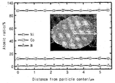
- 60 is a graph for explaining the atomic ratio of the positive electrode active material precursor according to Example 21 of the present invention.
- 61 is a graph for explaining the atomic ratio of the positive electrode active material according to Example 21 of the present invention.
- Example 62 is a graph measuring charge and discharge characteristics of the positive electrode active material according to Example 21 and Comparative Example 1 of the present invention.
- FIG. 63 is a graph measuring capacity retention characteristics of the positive electrode active material according to Example 21 and Comparative Example 1.
- FIG. 63 is a graph measuring capacity retention characteristics of the positive electrode active material according to Example 21 and Comparative Example 1.
- 65 is a graph illustrating lifetime characteristics of the positive electrode active material according to Examples 7, 14, 15, 16, 1, 7, 8, and 9 of the present invention. .
- 66 is a graph illustrating lifetime characteristics of the positive electrode active material according to Examples 7, 14, 15, 16, and 10 of the present invention.
- first, second, and third are used to describe various components, but these components should not be limited by these terms. These terms are only used to distinguish one component from another. Thus, what is referred to as a first component in one embodiment may be referred to as a second component in another embodiment.
- first component in one embodiment may be referred to as a second component in another embodiment.
- second component in another embodiment.
- Each embodiment described and illustrated herein also includes its complementary embodiment.
- the term 'and / or' is used herein to include at least one of the components listed before and after.
- the ratio of the first crystal structure in the specific portion is higher than the ratio of the second crystal structure, wherein the specific portion includes both the first crystal structure and the second crystal structure, In which the ratio of the first crystal structure is higher than the ratio of the second crystal structure, as well as the meaning that the specific portion has only the first crystal structure.
- the crystal system (triclinic), monoclinic (monoclinic), orthorhombic, tetragonal (tetragonal), trigonal (trigonal or rhombohedral), hexagonal (hexagonal) It can be composed of seven, and cubic (cubic).
- mol% refers to the content of any metal included in the positive electrode active material or the positive electrode active material precursor when the sum of the remaining metals other than lithium and oxygen in the positive electrode active material or the positive electrode active material precursor is 100%. It is interpreted as meaning that it represents.
- FIG. 1 is a view for explaining a positive electrode active material according to an embodiment of the present invention
- Figure 2 is a view showing an AB cross section of the positive electrode active material according to an embodiment of the present invention shown in Figure 1
- Figure 3 A diagram for describing a cathode active material according to a modified example of the embodiment of the present invention.
- the cathode active material 100 may include at least one of nickel, cobalt, manganese, or aluminum, lithium, and an additive metal.
- the cathode active material may be an oxide including at least one of nickel, cobalt, manganese, or aluminum, lithium, and an additive metal.
- the additive metal may be tungsten.
- the additive metal may include at least one of tungsten, molybdenum, niobium, tantalum, titanium, zirconium, bismuth, ruthenium, magnesium, zinc, gallium, vanadium, chromium, calcium, strontium, or tin. can do.
- the additive metal may include at least one of heavy metal elements having a specific gravity of 4 or more.
- the additive metal may include at least one of Group 4, Group 5, Group 6, Group 8, or Group 15 elements.
- the content of the additive metal (eg, tungsten) in the cathode active material 100 when the content of the additive metal (eg, tungsten) in the cathode active material 100 is 2 mol% or more, the capacity and lifespan characteristics of the cathode active material 100 may be reduced. Accordingly, according to one embodiment, the content of the additive metal (eg, tungsten) of the cathode active material 100 may be less than 2 mol%.
- the cathode active material 100 may be a metal oxide including nickel, lithium, the additive metal, and oxygen.
- the cathode active material 100 may be a metal oxide including nickel, cobalt, lithium, the additive metal, and oxygen.
- the cathode active material 100 may be a metal oxide including nickel, cobalt, manganese, lithium, the additive metal, and oxygen.
- the cathode active material 100 may be a metal oxide including nickel, cobalt, aluminum, lithium, the additive metal, and oxygen.
- Technical idea according to an embodiment of the present invention can be applied to the positive electrode active material containing a variety of materials.
- the concentration of the additive metal in the cathode active material 100 may be substantially constant (substantially).
- the concentration of the additive metal in the cathode active material 100, may be different or have a concentration gradient.
- the concentration of at least one of nickel, cobalt, manganese, or aluminum may be substantially constant in the cathode active material 100.
- the concentration of at least one of nickel, cobalt, manganese, or aluminum in the positive electrode active material 100 from the center of the particle toward the surface of the particle, the concentration gradient in the whole of the particle Or a concentration gradient in some of the particles.
- the cathode active material 100 may include a core part and a shell part having different concentrations of the core part and a metal (at least one of nickel, cobalt, manganese, or aluminum).
- Technical idea according to an embodiment of the present invention can be applied to the cathode active material of various structures and forms.
- the cathode active material may be represented by the following ⁇ Formula 1>.
- M1, M2, M3 is any one selected from nickel, cobalt, manganese, or aluminum, 0 ⁇ a ⁇ 1, 0 ⁇ b ⁇ 1, 0 ⁇ c ⁇ 1, 0 ⁇ d ⁇ 0.02, at least one of a, b, and c may be greater than 0, and M1, M2, M3, and M4 may be different metals.
- M4 may be the additive metal.
- the crystal structure according to the d value (mol% of M4) in the ⁇ Formula 1> can be controlled.
- the penetration amount of fluorine in the process including the positive electrode active material may be reduced (to be described later with reference to FIGS. 7 to 10).
- the cathode active material 100 may include a first crystal structure and a second crystal structure.
- the first crystal structure and the second crystal structure may be different crystal systems.
- the first crystal structure may be a cubic crystal structure
- the second crystal structure may be a trigonal or rhombohedral crystal structure.
- the crystal structure of the ionic cathode active material 100 may be confirmed by an ASTAR image.
- the first crystal structure may be any one of Cesium chloride structure, Rock-salt structure, Zincblende structure, or Weaire-Phelan structure.
- the cathode active material 100 may include a first portion 110 and a second portion 120.
- the first portion 110 may be a portion of the cathode active material 100 in which the ratio of the first crystal structure is higher than the ratio of the second crystal structure.
- the second portion 120 may be a portion of the cathode active material 100 in which the ratio of the second crystal structure is higher than the ratio of the first crystal structure. Unlike FIG. 2, the first portion 110 and the second portion 120 may not be clearly separated by a boundary line.
- the first portion 110 includes both the first crystal structure and the second crystal structure, wherein the ratio of the first crystal structure of the second crystal structure It is higher than the ratio, or in another embodiment, the first portion 110 may have only the first crystal structure.
- the second portion 120 includes both the first crystal structure and the second crystal structure, wherein the ratio of the second crystal structure of the first crystal structure Or higher than the ratio, or in another embodiment, the second portion 120 may have only the second crystal structure.
- the first portion 110 may surround at least a portion of the second portion 120.
- the thickness of the first portion 110 may be about 1 ⁇ m.
- the first portion 110 completely surrounds the second portion 120, that is, the core including the first portion 110 and the It may be a shell structure including the second portion 120.
- the cathode active material 100 may be a core-shell structure having a crystallographically different crystal system.
- the first portion 110 surrounds a portion of the second portion 120, and the second portion 120 is the positive electrode active material 100. It can make up part of the surface.
- the first portion 110 may be mainly located at the outside of the cathode active material 100, and the second portion 120 may be mainly located inside the cathode active material 100.
- the surface of the cathode active material 100 and a portion adjacent to the surface have a mainly or completely cubic crystal structure, and the center of the cathode active material 100 and a portion adjacent to the center are mainly or It may have a completely trigonal crystal structure.
- the cubic crystal structure ratio is higher than the trigonal crystal structure ratio, or only the cubic crystal structure is observed, and the positive electrode active material 100 is observed.
- the trigonal crystal structure ratio is higher than the cubic crystal structure ratio, or only the trigonal crystal structure can be observed.
- the ratio of the second portion 120 may be higher than the ratio of the first portion 110.
- the ratio of the second crystal structure may be higher than the ratio of the first crystal structure.
- the portion having the first crystal structure (or the first portion 110) and the portion having the second crystal structure (or the second portion 120) include the same material. can do.
- the cathode active material 100 is formed of an oxide including lithium, nickel, and tungsten
- the portion (or the second portion 120) may be formed of an oxide including lithium, nickel, and tungsten.
- the portion having the first crystal structure (or the first portion 110) and the portion having the second crystal structure (or the second portion 120) may be formed of an oxide including lithium, nickel, cobalt, manganese, and tungsten.
- the portion having the first crystal structure (or the first portion 110) and the portion having the second crystal structure (or the second portion 120) have the same chemical formula. Can be expressed. In other words, the portion having the first crystal structure (or the first portion 110) and the portion having the second crystal structure (or the second portion 120) may be chemically identical to each other.
- the positive electrode active material 100 includes the first portion 110 having a high ratio of the first crystal structure (eg, cubic crystal structure), and the first agent.
- the ratio of the second crystal structure eg, trigonal crystal structure
- the first portion 110 having a high ratio of the first crystal structure not only increases the mechanical strength of the cathode active material 100 but also reduces residual lithium on the surface of the cathode active material 100, thereby reducing the amount of the cathode active material. Capacity, life, and thermal stability of the secondary battery including the (100) can be improved.
- the ratio of the first crystal structure and the second crystal structure in the cathode active material 100 may be adjusted according to the content of the additive metal. Specifically, for example, as the content of the additive metal (eg, tungsten) increases, the ratio of the first crystal structure (eg, cubic system) in the cathode active material 100 may increase. have. When the content of the added metal is 2 mol% or more, the ratio of the first crystal structure (eg, cubic system) is increased, and the ratio of the second crystal structure (eg, trigonal system) is decreased, In the secondary battery including the cathode active material 100, it may be expected that the movement path of lithium ions is reduced. Accordingly, when the content of the additive metal (eg, tungsten) is 2 mol% or more, the charge / discharge characteristics of the secondary battery including the cathode active material 100 may decrease.
- the content of the additive metal eg, tungsten
- the content of the additive metal may be less than 2 mol%, and accordingly, the charge and discharge characteristics of the secondary battery including the cathode active material 100 may be improved. .
- FIG. 4 is a view for explaining the primary particles contained in the positive electrode active material according to an embodiment of the present invention.
- the cathode active material may include primary particles 30 and secondary particles in which the primary particles 30 are aggregated.
- the primary particles 30 may extend in a direction radiated toward the surface 20 of the secondary particles in one region inside the secondary particles.
- One region inside the secondary particles may be the center 10 of the secondary particles.
- the primary particles 30 may be in the form of a rod shape extending toward the surface 20 of the secondary particles in the region inside the secondary particles.
- the primary particles 30 having the rod shape that is, the primary particles 30 extending in the direction D of the surface portion 20 from the central portion 10 of the secondary particles.
- metal ions eg lithium ions
- migration paths of the electrolyte can be provided. Accordingly, the positive electrode active material according to the embodiment of the present invention may improve the charge and discharge efficiency of the secondary battery.
- the primary particles 30 relatively adjacent to the surface 20 of the secondary particles than the primary particles 30 relatively adjacent to the center 10 within the secondary particles. ) May have a longer length in the direction from the center 10 inside the secondary particles towards the surface 20 of the secondary particles. In other words, in at least a portion of the secondary particles that extend from the center 10 of the secondary particles to the surface 20, the length of the primary particles 30 is greater than the surface of the secondary particles. Closer to 20) may be increased.
- the content of the additive metal in the primary particles 30 is substantially May be identical to each other.
- the content of the additive metal in the primary particles 30 may be less than 2 mol%.
- the cathode active material according to the embodiment of the present invention may have a first crystal structure and a second crystal structure. Accordingly, some of the primary particles 30 may have both the first crystal structure and the second crystal structure. In addition, some of the primary particles 30 may have only the first crystal structure or only the second crystal structure. In this case, according to one embodiment, the closer to the surface 20 of the positive electrode active material, the proportion of the primary particles 30 having the first crystal structure (eg, cubic crystal structure) increases. In addition, the closer to the center 10 of the positive electrode active material, the proportion of the primary particles 30 having the second crystal structure (eg, trigonal crystal structure) may increase.
- the proportion of the primary particles 30 having the first crystal structure eg, cubic crystal structure
- the proportion of the primary particles 30 having the second crystal structure eg, trigonal crystal structure
- a base aqueous solution containing at least any one of nickel, cobalt, manganese, or aluminum, and an additional aqueous solution containing an additive metal are prepared.
- preparing the additive aqueous solution may include preparing a source containing the additive metal, and dissolving the source in a solvent to prepare the additive aqueous solution.
- the source may be tungsten oxide (WO 3 ).
- the solvent may be NaOH.
- the step of preparing the additive metal solution may include dissolving the source (eg, tungsten oxide) in a basic solution (eg, LiOH), and dissolving the LiOH in which the source is dissolved.
- a basic solution eg, LiOH
- Mixing with a solvent may include preparing the additive metal solution.
- the source can be easily dissolved.
- the solvent may adjust the pH in the reactor during the preparation of the positive electrode active material precursor using the aqueous solution, as described below.
- the base aqueous solution when the base aqueous solution includes nickel, for example, the base aqueous solution may be nickel sulfate. When the base aqueous solution includes cobalt, for example, the base aqueous solution may be cobalt sulfate. When the base aqueous solution includes manganese, the base aqueous solution may be manganese sulfate. When the base aqueous solution includes a plurality of metals in nickel, cobalt, manganese, or aluminum, the base aqueous solution may include a plurality of metal salt aqueous solutions.
- a cathode active material precursor doped with the additive metal in a metal hydroxide including at least one of nickel, cobalt, manganese, or aluminum may be prepared.
- an ammonia solution may be further provided to the reactor. The pH in the reactor may be controlled by the amount of the ammonia solution added and the solvent in which the additive metal is dissolved.
- the source including the additive metal may be dissolved in the base aqueous solution and provided in the reactor.
- the cathode active material precursor when the base solution includes nickel and the additive metal is tungsten, the cathode active material precursor may be represented by the following ⁇ Formula 2>. In Formula 2, x may be less than 1 and greater than 0.
- a cathode active material doped with the additive metal in at least one of nickel, cobalt, manganese, or aluminum and lithium may be prepared.
- the cathode active material may be represented as in the following ⁇ Formula 3>.
- the firing temperature of the positive electrode active material precursor and the lithium salt may be controlled according to the doping concentration of the additive metal. For example, as the doping concentration of the additive metal increases, the firing temperature of the cathode active material precursor and the lithium salt may increase. For example, when the doping concentration of the additive metal is 0.5 mol%, the firing temperature of the cathode active material precursor and the lithium salt is about 730 ° C., and when the doping concentration of the additive metal is 1.0%, the cathode active material precursor and When the calcination temperature of the lithium salt is about 760 ° C. and the doping concentration of the additive metal is 1.5 mol%, the calcination temperature of the cathode active material precursor and the lithium salt may be 790 ° C.
- the firing temperature of the cathode active material precursor and the lithium salt is not controlled according to the doping concentration of the additive metal, the charge and discharge characteristics of the secondary battery including the prepared cathode active material may be reduced. have.
- the firing temperature of the positive electrode active material precursor and the lithium salt is adjusted according to the doping concentration of the additive metal, the charge and discharge characteristics of the secondary battery including the positive electrode active material This can be improved.
- WO 3 powder was dissolved at 0.235 M concentration in 0.4 L of 1.5 M lithium hydroxide solution.
- the prepared solution was dissolved in 9.6 L of 4 M sodium hydroxide solution to prepare an aqueous solution of an additive metal in which W was dissolved.
- 10 liters of distilled water was added to the coprecipitation reactor (capacity 40L, the output of the rotary motor more than 750W), and N 2 gas was supplied to the reactor at a rate of 6 liters / minute, and stirred at 350 rpm while maintaining the temperature of the reactor at 45 ° C. .
- Aqueous solution of nickel sulfate at 2 M concentration was prepared at 0.561 liter / hour, and ammonia solution at 10.5 M concentration at 0.128 liter / hour was continuously added to the reactor for 15 to 35 hours.
- ammonia solution at 10.5 M concentration at 0.128 liter / hour was continuously added to the reactor for 15 to 35 hours.
- for pH adjustment and the addition of tungsten by supplying the aqueous solution was added to prepare a Ni 0 .995 W 0.005 (OH) 2 metal complex hydroxide.
- Ni 0 .995 W 0.005 (OH) 2 a metal complex hydroxide was filtered and dried for 12 hours in a vacuum dryer 110 °C After washing with water.
- Example 1 LiNi 0.995 W 0.005 O 2 710 °C
- Example 2 LiNi 0.995 W 0.005 O 2 730 °C
- Example 3 LiNi 0.995 W 0.005 O 2 750 °C
- Example 4 LiNi 0.995 W 0.005 O 2 770 °C
- Example 6 LiNi 0 .99 W 0 in accordance with the. 01 O 2 cathode active material powder was prepared.
- Example 7 LiNi 0 .99 W 0 in accordance with the. 01 O 2 cathode active material powder was prepared.
- Example 8 LiNi 0 .99 W 0 in accordance with the. 01 O 2 cathode active material powder was prepared.
- Example 5 LiNi 0.99 W 0.01 O 2 730 °C
- Example 6 LiNi 0.99 W 0.01 O 2 750 °C
- Example 7 LiNi 0.99 W 0.01 O 2 760 °C
- Example 8 LiNi 0.99 W 0.01 O 2 770 °C
- Example 11 Ni 0 .985 W 0.015 ( OH) 2 to the metal complex hydroxide and lithium hydroxide (LiOH) and baked at 810 °C, LiNi 0.985 W 0.015 O 2 positive electrode of Example 11 An active material powder was prepared.
- Example 9 LiNi 0.985 W 0.015 O 2 770 °C
- Example 10 LiNi 0.985 W 0.015 O 2 790 °C
- Example 11 LiNi 0.985 W 0.015 O 2 810 °C
- Ni (OH) 2 metal composite hydroxide was filtered, washed with water, and dried in a 110 ° C. vacuum dryer for 12 hours.
- Ni (OH) 2 metal composite hydroxide and lithium hydroxide (LiOH) were mixed at a molar ratio of 1: 1, and then heated at a temperature increase rate of 2 ° C./min, and then maintained at 450 ° C. for 5 hours, followed by preliminary firing. Baking at 10 ° C for 10 hours to prepare a LiNiO 2 cathode active material powder according to Comparative Example 1.
- Cathode active materials according to Examples 1 to 12 and Comparative Example 1 may be summarized as shown in Table 1 below.
- Example 1 LiNiO 2 Examples 1-4 LiNi 0.995 W 0.005 O 2 Examples 5-8 LiNi 0.99 W 0.01 O 2 Examples 9-11 LiNi 0.985 W 0.015 O 2 Example 12 LiNi 0.98 W 0.02 O 2
- Residual lithium according to Example 8 and Comparative Example 1 of the present invention was measured as shown in Table 5 below.
- the amount of residual lithium of the positive electrode active material according to Example 8 is about 6000 ppm lower than that of the residual lithium of the positive electrode active material according to Comparative Example 1.
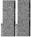
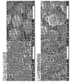
- FIG 5 is an ASTAR image of the positive electrode active material according to Comparative Example 1 of the present invention
- Figure 6 is an ASTAR image of the positive electrode active material according to Example 7 of the present invention.
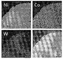
- FIG. 7 is EDS mapping data (before charging and discharging) of the positive electrode active material according to Comparative Example 1 of the present invention
- Figure 8 is EDS mapping data (before charging and discharging) of the positive electrode active material according to Example 7 of the present invention
- 9 is EDS mapping data (after charging and discharging) of the cathode active material according to Comparative Example 1 of the present invention
- FIG. 10 is EDS mapping data (after performing charging and discharging) of the cathode active material according to Example 7 of the present invention.
- tungsten which is an additive metal, is substantially uniformly distributed in the positive electrode active material particles.
- FIG. 11 is an SEM image of a cathode active material according to Comparative Example 1 of the present invention
- FIG. 12 is an SEM image of a cathode active material according to Example 7 of the present invention
- FIG. 13 is a cathode image of an anode active material according to Example 10 of the present invention. It is an SEM image
- FIG. 14 is XRD result data of the positive electrode active material according to Example 2, Example 7, and Comparative Example 1.
- Figure 15 is a graph measuring charge and discharge characteristics of the positive electrode active material according to Example 2, Example 7, Example 10, Example 12, and Comparative Example 1 of the present invention
- Figure 16 is a second embodiment of the present invention, It is a graph measuring the capacity retention characteristics of the positive electrode active material according to Example 7, Example 10, Example 12, and Comparative Example 1.
- a half cell was prepared using the cathode active material according to Comparative Example 1, Example 2, Example 7, Example 10, and Example 12, cut off 2.7 to 4.3 V, 0.1
- the discharge capacity was measured at C and 30 ° C., and the discharge capacity was measured according to the number of charge and discharge cycles at cut off at 2.7 ⁇ 4.3 V, 0.5 C and 30 ° C. Measurement results are shown in FIG. 15, FIG. 16, and Table 6 below.
- Example 1 247.5 96.8% 242.3 97.9% 232.5 93.9% 100 73.7%
- Example 2 246.7 96.1% 242.5 98.3% 233.1 94.5% 100 83.2%
- Example 7 244.0 95.6% 240.0 98.4% 233.2 95.6% 100 88.2% Conduct 10 240.8 94.9% 235.4 97.8% 226.6 94.1% 100 89.8%
- Example 12 201.4 96.0% 182.5 90.6% 160.7 79.8% 15 98.4%
- Example 17 is a graph measuring capacity retention characteristics of the positive electrode active material according to Example 7 and Comparative Example 1 of the present invention.
- FIG. 18 is an EIS measurement graph of a cathode active material according to Comparative Example 1 of the present invention
- FIG. 19 is an EIS measurement graph of a cathode active material according to Example 7 of the present invention.
- secondary batteries including the cathode active materials according to Comparative Example 1 and Example 7 were prepared, and electrochemical impedances according to charge and discharge cycles were measured.
- 20 to 23 is a graph measuring the differential capacity of the positive electrode active material according to Examples 2, 7, 7, 10, and 3 and Comparative Example 1 of the present invention.
- Figure 24 is a graph measuring the charge and discharge characteristics of the positive electrode active material according to Examples 1 to 4 and Comparative Example 1 of the present invention
- Figure 25 is the capacity of the positive electrode active material according to Examples 1 to 4 and Comparative Example 1 of the present invention It is a graph measuring retention characteristics.
- a half cell was prepared using the cathode active material according to Comparative Example 1 and Examples 1 to 4, and the discharge capacity was measured at cut-off 2.7 to 4.3 V, 0.1 C, and 30 ° C., and cut off 2.7 to 4.3 V, The discharge capacity was measured according to the number of charge and discharge cycles at 0.5C and 30 ° C. Measurement results are shown in FIG. 24, FIG. 25, and Table 9 below.
- Example 1 247.5 96.8% 242.3 97.9% 232.5 93.9% 100 73.7%
- Example 1 243.9 96.0% 239.0 98.0% 229.3 94.0% 100 75.2%
- Example 2 246.7 96.1% 242.5 98.3% 233.1 94.5% 100 83.2%
- Example 3 247.7 96.5% 241.4 97.5% 230.5 93.1% 100 80.8%
- Example 4 239.3 93.8% 236.7 98.9% 224.5 93.8% 100 80.5%
- the secondary battery prepared using the positive electrode active material according to Examples 1 to 4 It can be confirmed that the discharge capacity characteristics and life characteristics of the remarkably excellent.
- the firing temperature of the cathode active material precursor and the lithium salt may be higher than that of the cathode active material manufacturing method according to Comparative Example 1 in which the additive metal is not doped.
- controlling the firing temperature of the positive electrode active material precursor and the lithium salt to about 730 ° C. is an efficient method of improving the charge / discharge characteristics.
- FIG. 26 is a graph measuring the charge and discharge characteristics of the positive electrode active material according to Examples 5 to 8 and Comparative Example 1
- Figure 27 is a capacity of the positive electrode active material according to Examples 5 to 8 and Comparative Example 1 of the present invention It is a graph measuring retention characteristics.
- a half cell was prepared using the cathode active material according to Comparative Example 1, Examples 5 to 8, and the cut capacity was measured at cut off 2.7 to 4.3 V, 0.1 C, and 30 ° C., and cut off 2.7 to 4.3 V, The discharge capacity was measured according to the number of charge and discharge cycles at 0.5C and 30 ° C. Measurement results are shown in FIG. 26, FIG. 27, and Table 10 below.
- Example 1 247.5 96.8% 242.3 97.9% 232.5 93.9% 100 73.7%
- Example 5 242.1 96.0% 236.1 97.5% 226.1 93.4% 100 87.6%
- Example 6 238.1 95.1% 233.9 98.2% 226.5 95.1% 100 88.6%
- Example 7 244.0 95.6% 240.0 98.4% 233.2 95.6% 100 88.2%
- Example 8 245.0 95.6% 241.7 98.6% 234.9 95.9% 100 86.5%
- the secondary battery prepared using the positive electrode active material according to Examples 5 to 8, compared to the secondary battery prepared using the positive electrode active material according to Comparative Example 1 It can be confirmed that the discharge capacity characteristics and life characteristics of the remarkably excellent.
- the firing temperature of the positive electrode active material precursor and the lithium salt is high as compared with the method for preparing the positive electrode active material according to Comparative Example 1 in which the additive metal is not doped.
- the firing temperature of the positive electrode active material precursor and the lithium salt is increased. It can be seen that it is an efficient way to improve efficiency.
- Figure 29 is a capacity of the positive electrode active material according to Examples 9 to 11 and Comparative Example 1 of the present invention It is a graph measuring retention characteristics.
- Half cells were prepared using the cathode active materials according to Comparative Example 1 and Examples 9 to 11, and the cut-off capacity was measured at cut-off 2.7 to 4.3 V, 0.1 C, and 30 ° C., and cut off at 2.7 to 4.3 V, The discharge capacity was measured according to the number of charge and discharge cycles at 0.5C and 30 ° C. Measurement results are shown in FIG. 28, FIG. 29, and Table 11 below.
- the cathode active material was compared with the method for preparing a cathode active material according to Comparative Example 1 in which the additive metal was not doped. It can be seen that the firing temperature of the precursor and the lithium salt is high. In addition, the content of the added metal is 1.5 mol% as compared with that of the content of the added metal is 0.5 mol% as in Examples 1 to 4, and the content of the added metal is 1.0 mol% as in Examples 5 to 8. When increasing, it can be seen that increasing the firing temperature of the positive electrode active material precursor and the lithium salt is an efficient method of improving the charge and discharge efficiency.
- Ni (OH) 2 metal composite hydroxide was prepared by the same process as Comparative Example 1 described above.
- Ni (OH) 2 metal composite hydroxide was filtered, washed with water, and dried in a 110 ° C. vacuum dryer for 12 hours.
- LiNi 0.995 W 0.005 O 2 cathode active material powder according to Comparative Example 2 was mixed with Ni (OH) 2 metal composite hydroxide and WO 3 powder in a molar ratio of 99.5: 0.5, mixed with lithium hydroxide (LiOH), and calcined at 650 ° C. Was prepared.
- LiNiO 2 powder was prepared by the same process as Comparative Example 1 described above.
- the prepared LiNiO 2 powder and WO 3 were mixed in a molar ratio of 99.75: 0.25, ball-milled, and then heat-treated at 400 ° C. to prepare a W coating 0.25 mol% LiNiO 2 cathode active material according to Comparative Example 4.
- the positive electrode active material according to Comparative Example 2 to Comparative Example 4 may be arranged as shown in Table 12 below.
- FIG. 30 is a graph measuring the charge and discharge characteristics of the positive electrode active material according to Examples 2, 7, 10, and Comparative Examples 1 to 5 of the present invention
- Figure 31 is a Example 2
- Example of the present invention 7 Example 10
- Comparative Examples 1 to 5 is a graph measuring the capacity retention characteristics of the positive electrode active material.
- WO 3 powder was dissolved in 0.4 L of 1.5 M lithium hydroxide solution at a concentration of 0.47 M.
- the prepared solution was dissolved in 9.6 L of 4 M sodium hydroxide solution to prepare a 10 L aqueous solution of the additive metal in which W was dissolved.
- 10 liters of distilled water was put into a coprecipitation reactor (capacity 40L, output of a rotating motor of 750W or more), N 2 gas was supplied to the reactor at a rate of 6 liters / minute, and stirred at 350 rpm while maintaining the temperature of the reactor at 45 ° C.
- Ni 0 . 88 Co 0 .11 W 0.01 (OH ) 2 a metal complex hydroxide was filtered and dried for 12 hours in a vacuum dryer 110 °C After washing with water.
- the metal composite hydroxide and lithium hydroxide (LiOH) were mixed at a molar ratio of 1: 1, and then heated at a temperature rising rate of 2 ° C./min, and then maintained at 450 ° C. for 5 hours, followed by prefiring at 750 ° C. for 10 hours.
- a powder of LiNi 0.88 Co 0.11 W 0.01 O 2 cathode active material according to Example 13 was prepared.
- Ni 0 . 885 Co 0 .115 (OH) 2 the metal complex hydroxide was filtered and dried for 12 hours in a vacuum dryer 110 °C After washing with water.
- the metal composite hydroxide and lithium hydroxide (LiOH) were mixed at a molar ratio of 1: 1, and then heated at a heating rate of 2 ° C./min, and then maintained at 450 ° C. for 5 hours, followed by prefiring at 700 ° C. for 10 hours.
- LiNi 0.885 Co 0.115 O 2 cathode active material powder according to Comparative Example 6 was prepared.
- FIG. 32 is a XRD result graph of the positive electrode active material according to Example 13 of the present invention
- FIG. 33 is a SEM photograph of the positive electrode active material precursor and the positive electrode active material according to Comparative Example 6 of the present invention
- FIG. 34 is a thirteenth embodiment of the present invention. SEM picture of the positive electrode active material precursor and the positive electrode active material according to.
- the tungsten is doped in the positive electrode active material according to Example 13 of the present invention, and compared with the positive electrode active material according to Comparative Example 6, it is confirmed that the number of relatively collapsed particles Can be.
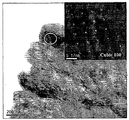
- 35 is a TEM photograph and SEAD pattern of the positive electrode active material according to Example 13 of the present invention.
- FIG. 35 it can be seen that a part of the positive electrode active material including tungsten according to the thirteenth embodiment of the present invention, that is, a cubic structure is observed on the surface of the positive electrode active material particles including tungsten according to the thirteenth embodiment. have.
- FIG. 36 is EPMA data of a positive electrode active material according to Example 13 of the present invention
- FIG. 37 is a diagram illustrating TEM-EDX mapping of the positive electrode active material according to Example 13 of the present invention.
- Table 14 shows the concentration of each element in the center and the surface of the positive electrode active material particles based on the EPMA data shown in FIG. 36, and Table 15 shows the positive electrode based on the TEM-EDX mapping shown in FIG. The overall composition of the active material is shown.
- FIG. 38 is a graph measuring charge and discharge characteristics of the positive electrode active material according to Example 13 and Comparative Example 6 of the present invention
- FIG. 39 is a measurement of capacity retention characteristics of the positive electrode active material according to Example 13 and Comparative Example 6 of the present invention. One graph.
- a half cell was prepared using the cathode active material according to Example 13 and Comparative Example 6, and the discharge capacity was measured under the conditions of cut off 2.7 to 4.3 V, 0.1 C, and 30 ° C., and cut off 2.7 to 4.3 V and 0.5 C. , Discharge capacity according to the number of charge and discharge cycles at 30 °C condition was measured. Measurement results are shown in FIGS. 38, 39 and Table 16 below.
- Example 13 doped with the additive metal, it was confirmed that the capacity characteristics and the charge-discharge characteristics were superior to those of Comparative Example 6 in which the additive metal was not doped. Can be.
- WO 3 powder was dissolved in 0.4 L of 1.5 M lithium hydroxide solution at a concentration of 0.47 M.
- the prepared solution was dissolved in 9.6 L of 4 M sodium hydroxide solution to prepare a 10 L aqueous solution of the additive metal in which W was dissolved.
- 10 liters of distilled water was put into a coprecipitation reactor (capacity 40L, output of a rotating motor of 750W or more), N 2 gas was supplied to the reactor at a rate of 6 liters / minute, and stirred at 350 rpm while maintaining the temperature of the reactor at 45 ° C.
- Ni 0 . 89 Co 0 . 05 Mn 0 .05 W 0.01 (OH ) 2 a metal complex hydroxide was filtered and dried for 12 hours in a vacuum dryer 110 °C After washing with water.
- the metal composite hydroxide and lithium hydroxide (LiOH) were mixed at a molar ratio of 1: 1, and then heated at a temperature rising rate of 2 ° C./min, and then maintained at 450 ° C. for 5 hours, followed by prefiring at 750 ° C. for 10 hours. Firing was performed to prepare LiNi 0.89 Co 0.05 Mn 0.05 W 0.01 O 2 cathode active material powder according to Example 14.
- Ni 0 . 90 Co 0 . 05 Mn 0 .05 (OH) 2 the metal complex hydroxide was filtered and dried for 12 hours in a vacuum dryer 110 °C After washing with water.
- the metal composite hydroxide and lithium hydroxide (LiOH) were mixed at a molar ratio of 1: 1, and then heated at a temperature rising rate of 2 ° C./min, and then maintained at 450 ° C. for 5 hours, followed by prefiring at 750 ° C. for 10 hours.
- LiNi 0.90 Co 0.05 Mn 0.05 O 2 cathode active material powder according to Comparative Example 7 was prepared.
- FIG. 40 is an SEM image of a cathode active material precursor according to Comparative Example 7 of the present invention
- FIG. 41 is an SEM image of a cathode active material precursor according to Example 14 of the present invention
- FIG. 42 is a cathode according to Comparative Example 7 of the present invention.
- SEM image of the active material Figure 43 is a SEM image of the positive electrode active material according to Example 14 of the present invention.
- Figure 45 is a measurement of the capacity retention characteristics of the positive electrode active material according to Example 14 and Comparative Example 7 of the present invention One graph.
- WO 3 powder was dissolved in 0.4 L of 1.5 M lithium hydroxide solution at a concentration of 0.47 M.
- the prepared solution was dissolved in 9.6 L of 4 M sodium hydroxide solution to prepare a 10 L aqueous solution of the additive metal in which W was dissolved.
- 10 liters of distilled water was put into a coprecipitation reactor (capacity 40L, output of a rotating motor of 750W or more), N 2 gas was supplied to the reactor at a rate of 6 liters / minute, and stirred at 350 rpm while maintaining the temperature of the reactor at 45 ° C.
- Ni 0 . 80 Co 0 . 15 Mn 0 .05 (OH) 2 the metal complex hydroxide was filtered and dried for 12 hours in a vacuum dryer 110 °C After washing with water.
- the metal composite hydroxide and lithium hydroxide (LiOH) were mixed at a molar ratio of 1: 1, and then heated at a heating rate of 2 ° C./min, and then maintained at 450 ° C. for 5 hours, followed by prefiring at 780 ° C. for 10 hours.
- a powder of LiNi 0.80 Co 0.15 Mn 0.05 O 2 cathode active material according to Comparative Example 8 was prepared.
- FIG. 46 is a graph showing the XRD results of the positive electrode active materials according to Example 15 and Comparative Example 8 of the present invention
- FIG. 47 is a graph measuring charge and discharge characteristics of the positive electrode active materials according to Example 15 and Comparative Example 8 of the present invention
- 48 is a graph measuring capacity retention characteristics of the positive electrode active material according to Example 15 and Comparative Example 8.
- a half cell was prepared using the positive electrode active material according to Example 15 and Comparative Example 8, and the discharge capacity was measured under the conditions of cut off 2.7 to 4.3 V, 0.1 C and 30 ° C., and cut off 2.7 to 4.3 V and 0.5 C. , Discharge capacity according to the number of charge and discharge cycles at 30 °C condition was measured. Measurement results are shown in FIG. 47, FIG. 48, and Table 18 below.
- Example 15 doped with the additive metal, it was confirmed that the capacity characteristics and charge and discharge characteristics are excellent compared to Comparative Example 8 in which the additive metal is not doped Can be.
- WO 3 powder was dissolved in 0.4 L of 1.5 M lithium hydroxide solution at a concentration of 0.47 M.
- the prepared solution was dissolved in 9.6 L of 4 M sodium hydroxide solution to prepare a 10 L aqueous solution of the additive metal in which W was dissolved.
- 10 liters of distilled water was put into a coprecipitation reactor (capacity 40L, output of a rotating motor of 750W or more), N 2 gas was supplied to the reactor at a rate of 6 liters / minute, and stirred at 350 rpm while maintaining the temperature of the reactor at 45 ° C.
- nickel: cobalt: manganese 60: 20: 20, molar ratio
- 10.5M ammonia solution is 0.128 liters / hour.
- LiNi 0.59 Co 0.20 Mn 0.20 W 0.01 O 2 cathode active material powder according to Example 16 was prepared.
- Ni 0 . 60 Co 0 . 20 Mn 0 .20 (OH) 2 the metal complex hydroxide was filtered and dried for 12 hours in a vacuum dryer 110 °C After washing with water.
- the metal composite hydroxide and lithium hydroxide (LiOH) were mixed at a molar ratio of 1: 1, and then heated at a heating rate of 2 ° C./min, and then maintained at 450 ° C. for 5 hours, followed by prefiring at 850 ° C. for 10 hours. Firing was performed to prepare LiNi 0.60 Co 0.20 Mn 0.20 O 2 cathode active material powder according to Comparative Example 9.
- FIG. 49 is a graph showing the XRD results of the cathode active materials according to Example 16 and Comparative Example 9 of the present invention
- FIG. 50 is a graph measuring charge and discharge characteristics of the cathode active materials according to Example 16 and Comparative Example 9 of the present invention
- 51 is a graph measuring capacity retention characteristics of the positive electrode active material according to Example 16 and Comparative Example 9.
- a half cell was prepared using the positive electrode active material according to Example 16 and Comparative Example 9, and the discharge capacity was measured under the conditions of cut off 2.7 to 4.3 V, 0.1 C, and 30 ° C., and cut off 2.7 to 4.3 V and 0.5 C. , Discharge capacity according to the number of charge and discharge cycles at 30 °C condition was measured. Measurement results are shown in FIG. 50, FIG. 51, and Table 19 below.
- Example 16 doped with the additive metal As can be seen in Figures 50, 51, and Table 19, in Example 16 doped with the additive metal, it was confirmed that the capacity characteristics and charge and discharge characteristics are superior to Comparative Example 9 without the addition metal doped. Can be.
- Na 2 MoO 4 powder was dissolved in 10 L of a 4 M sodium hydroxide solution at a concentration of 0.019 M to prepare a 10 L aqueous solution of the additive metal in which Mo was dissolved.
- 10 liters of distilled water was put into a coprecipitation reactor (capacity 40L, output of a rotating motor of 750W or more), N 2 gas was supplied to the reactor at a rate of 6 liters / minute, and stirred at 350 rpm while maintaining the temperature of the reactor at 45 ° C.
- Aqueous solution of nickel sulfate at 2 M concentration was prepared at 0.561 liter / hour, and ammonia solution at 10.5 M concentration at 0.128 liter / hour was continuously added to the reactor for 15 to 35 hours.
- the addition aqueous metal solution was supplied for pH adjustment and Mo-doping.
- Ni 0 . 99 Mo 0 .01 (OH) 2 the metal complex hydroxide was filtered and dried for 12 hours in a vacuum dryer 110 °C After washing with water.
- the metal composite hydroxide and lithium hydroxide (LiOH) were mixed at a molar ratio of 1: 1, and then heated at a heating rate of 2 ° C./min, and then maintained at 450 ° C. for 5 hours, followed by prefiring at 730 ° C. for 10 hours. Firing was performed to prepare a LiNi 0.99 Mo 0.01 O 2 cathode active material powder according to Example 17.
- FIG. 52 is a graph measuring charge and discharge characteristics of the positive electrode active material according to Example 17 and Comparative Example 1 of the present invention
- FIG. 53 is a graph measuring capacity retention characteristics of the positive electrode active material according to Example 17 and Comparative Example 1.
- a half cell was prepared using the positive electrode active material according to Example 17, and the discharge capacity was measured at cut off 2.7 to 4.3 V, 0.1 C, and 30 ° C., and cut off at 2.7 to 4.3 V, 0.5 C, and 30 ° C.
- the discharge capacity was measured according to the number of charge and discharge cycles, and compared with the half cell prepared using the positive electrode active material according to Comparative Example 1. Comparison results are shown in FIG. 52, FIG. 53, and Table 20 below.
- WO 3 powder was dissolved in 0.4 L of 1.5 M lithium hydroxide solution at a concentration of 0.47 M.
- the prepared solution was dissolved in 9.6 L of a 4 M sodium hydroxide solution to prepare a 10 L aqueous solution of pre-added metal in which W was dissolved.
- Na 2 MoO 4 powder was dissolved at 0.019 M in the pre-added metal solution to prepare 10 L of an additive metal solution in which W and Mo were dissolved.
- Ni 0 .98 W 0. 01 Mo 0 .01 (OH) 2 produced metal complex hydroxide, and dried for 12 hours at 110 °C vacuum dryer after washing with water.
- the metal composite hydroxide and lithium hydroxide (LiOH) were mixed at a molar ratio of 1: 1, and then heated at a heating rate of 2 ° C./min, and then maintained at 450 ° C. for 5 hours, followed by prefiring at 760 ° C. for 10 hours. Firing was performed to prepare LiNi 0.98 W 0.01 Mo 0.01 O 2 cathode active material powder according to Example 18.
- FIG. 54 is a graph measuring charge and discharge characteristics of a positive electrode active material according to Example 18 and Comparative Example 1
- FIG. 55 is a graph measuring capacity retention characteristics of the positive electrode active material according to Example 18 and Comparative Example 1.
- a half cell was prepared using the cathode active material according to Example 18, and the discharge capacity was measured at cut off 2.7 to 4.3 V, 0.1 C, and 30 ° C., and cut off at 2.7 to 4.3 V, 0.5 C, and 30 ° C.
- the discharge capacity was measured according to the number of charge and discharge cycles at and compared with the half cell prepared using the cathode active material according to Comparative Example 1. Comparative results are shown in FIG. 54, FIG. 55, and Table 21 below.
- Ni 0 . 995 Zr 0 .005 (OH) 2 the metal complex hydroxide was filtered and dried for 12 hours in a vacuum dryer 110 °C After washing with water.
- the metal composite hydroxide and lithium hydroxide (LiOH) were mixed at a molar ratio of 1: 1, and then heated at a heating rate of 2 ° C./min, and then maintained at 450 ° C. for 5 hours, followed by prefiring at 650 ° C. for 10 hours. Firing was performed to prepare LiNi 0.995 Zr 0.005 O 2 cathode active material powder according to Example 19.
- FIG. 56 is a graph measuring charge and discharge characteristics of a cathode active material according to Example 19 and Comparative Example 1 of the present invention
- FIG. 57 is a graph measuring capacity retention characteristics of the cathode active material according to Example 19 and Comparative Example 1 .
- a half cell was prepared using the cathode active material according to Example 19, and the discharge capacity was measured at cut off at 2.7 to 4.3 V, 0.1 C, and 30 ° C., and cut off at 2.7 to 4.3 V, 0.5 C, and 30 ° C.
- the discharge capacity was measured according to the number of charge and discharge cycles at and compared with the half cell prepared using the cathode active material according to Comparative Example 1. The comparison results are shown in FIG. 56, FIG. 57, and Table 22 below.
- Example 19 doped with the additive metal it was confirmed that the capacity characteristics and charge and discharge characteristics are superior to Comparative Example 1 without the addition metal doped. Can be.
- WO 3 powder was dissolved in 0.4 L of 1.5 M lithium hydroxide solution at a concentration of 0.47 M.
- the prepared solution was dissolved in 9.6 L of 4 M sodium hydroxide solution to prepare a 10 L aqueous solution of the additive metal in which W was dissolved.
- Ni 0 .985 W 0. 01 Zr 0 .005 (OH) 2 was filtered off and dried to give the metal complex hydroxide, for 12 hours at 110 °C vacuum dryer after washing with water.
- the metal composite hydroxide and lithium hydroxide (LiOH) were mixed at a molar ratio of 1: 1, and then heated at a heating rate of 2 ° C./min, followed by preliminary firing at 450 ° C. for 5 hours, followed by 10 hours at 790 ° C.
- LiNi 0.985 W 0.01 Zr 0.005 O 2 cathode active material powder according to Example 20 was prepared.
- FIG. 58 is a graph measuring charge and discharge characteristics of a positive electrode active material according to Example 20 and Comparative Example 1
- FIG. 59 is a graph measuring capacity retention characteristics of the positive electrode active material according to Example 20 and Comparative Example 1.
- a half cell was prepared using the cathode active material according to Example 20, and the discharge capacity was measured at cut off at 2.7 to 4.3 V, 0.1 C, and 30 ° C., and cut off at 2.7 to 4.3 V, 0.5 C, and 30 ° C.
- the discharge capacity was measured according to the number of charge and discharge cycles at and compared with the half cell prepared using the cathode active material according to Comparative Example 1. Comparison results are shown in FIG. 58, FIG. 59, and Table 23 below.
- Example 20 doped with the additive metal, it is confirmed that the capacity characteristics and charge and discharge characteristics are superior to Comparative Example 1 without the addition metal doped Can be.
- WO 3 powder was dissolved in 0.4 L of 1.5 M lithium hydroxide solution at a concentration of 0.47 M.
- the prepared solution was dissolved in 9.6 L of 4 M sodium hydroxide solution to prepare a 10 L aqueous first additive metal solution in which W was dissolved.
- Na 2 MoO 4 powder was dissolved in 0.019 M concentration in 10 L of a 4 M sodium hydroxide solution to prepare a 10 L aqueous solution of a second additive metal in which Mo was dissolved.
- the prepared Ni 0 .99 W 0. 005 Mo 0 .005 (OH) 2 the metal complex hydroxide was filtered and dried for 12 hours in a vacuum dryer 110 °C After washing with water.
- the metal composite hydroxide and lithium hydroxide (LiOH) were mixed at a molar ratio of 1: 1, and then heated at a heating rate of 2 ° C./min, and then maintained at 450 ° C. for 5 hours, followed by prefiring at 770 ° C. for 10 hours.
- LiNi 0.99 W 0.005 Mo 0.005 O 2 cathode active material powder according to Example 21 was prepared.
- FIG. 60 is a graph for explaining the atomic ratio of the positive electrode active material precursor according to the twenty-first embodiment of the present invention
- FIG. 61 is a graph for explaining the atomic ratio of the positive electrode active material according to the twenty-first embodiment of the present invention
- FIG. 63 is a graph measuring charge and discharge characteristics of a positive electrode active material according to Example 21 and Comparative Example 1
- FIG. 63 is a graph measuring capacity retention characteristics of the positive electrode active material according to Example 21 and Comparative Example 1.
- FIG. 60 is a graph for explaining the atomic ratio of the positive electrode active material precursor according to the twenty-first embodiment of the present invention
- FIG. 61 is a graph for explaining the atomic ratio of the positive electrode active material according to the twenty-first embodiment of the present invention
- FIG. 63 is a graph measuring charge and discharge characteristics of a positive electrode active material according to Example 21 and Comparative Example 1
- FIG. 63 is a graph measuring capacity retention characteristics of the positive electrode active material according to Example 21 and Comparative Example 1.
- Ni 0.99 W 0.005 Mo 0.005 (OH) 2 metal composite hydroxide as a cathode active material precursor according to Example 21 was prepared, and the atomic ratios thereof were measured as shown in FIG. 60 and Table 24.
- cathode active material according to Example 21 LiNi 0 .99 W 0. 005 Mo 0. 005 O 2
- the atomic ratio of was measured as shown in Figure 61 and Table 25.
- a half cell was prepared using the cathode active material according to Example 21, and the discharge capacity was measured under cut off conditions of 2.7 to 4.3 V, 0.1 C, and 30 ° C., and cut off 2.7 to 4.3 V, 0.5 C, and 30 degrees. Discharge capacity was measured according to the number of charge-discharge cycles under the condition of °C, and compared with the half cell prepared using the positive electrode active material according to Comparative Example 1. The comparison results are shown in FIGS. 62, 63, and Table 26 below.
- Example 21 doped with the additive metal, it was confirmed that the capacity characteristics and the charge-discharge characteristics are superior compared to Comparative Example 1 without the addition metal doped. Can be.
- 64 is a graph measuring charge and discharge characteristics of a positive electrode active material according to Examples 7, Examples 14, 15, 16, Comparative Example 1, Comparative Example 7, Comparative Example 8, and Comparative Example 9 of the present invention
- 65 is a measurement of the life characteristics of the positive electrode active material according to Example 7, Example 14, Example 15, Example 16, Comparative Example 1, Comparative Example 7, Comparative Example 8, and Comparative Example 9 of the present invention It is a graph.
- Example 7 (LNO + W), Example 14 (NCM 900505 + W), Example 15 (NCM 801505 + W), Example 16 (NCM 622 + W), Comparative Example
- the positive electrode active material according to the embodiments including the additive metal has superior capacity characteristics and charge / discharge characteristics as compared with the positive electrode active material according to the comparative examples that do not include the additive metal. have.
- the initial capacity increases as the nickel content increases, but it can be seen that the decreased capacity increases significantly according to the number of charge and discharge cycles.
- manufacturing a cathode active material including an additive metal according to embodiments of the present invention is an effective method for simultaneously implementing high capacity characteristics and long life characteristics.
- 66 is a graph illustrating lifetime characteristics of the positive electrode active material according to Examples 7, 14, 15, 16, and 10 of the present invention.
- NCA 82 ECO NCA cathode active material containing 82 mol% of Ni, Co, and Al sold by Ecopro was prepared, Examples 7, 14, 15, and The cathode active material according to Example 16 was compared with the life characteristics.
- a cathode active material and a method of manufacturing the same according to an embodiment of the present invention can be used in a lithium secondary battery and a method of manufacturing the same.
- the lithium secondary battery including the cathode active material according to the embodiment of the present invention may be utilized in various industrial fields such as a portable mobile device, an electric vehicle, and an ESS.
Landscapes
- Chemical & Material Sciences (AREA)
- Organic Chemistry (AREA)
- Inorganic Chemistry (AREA)
- Chemical Kinetics & Catalysis (AREA)
- Electrochemistry (AREA)
- General Chemical & Material Sciences (AREA)
- Composite Materials (AREA)
- Engineering & Computer Science (AREA)
- Manufacturing & Machinery (AREA)
- Battery Electrode And Active Subsutance (AREA)
- Inorganic Compounds Of Heavy Metals (AREA)
Abstract
양극활물질이 제공된다. 상기 양극활물질은, 니켈, 코발트, 망간, 또는 알루미늄 중에서 적어도 어느 하나, 리튬, 및 첨가 금속을 포함하되, 상기 첨가 금속은, 니켈, 코발트, 망간, 및 알루미늄과 다른 원소를 포함하고, 상기 첨가 금속의 함량은 평균 2mol% 미만일 수 있다.
Description
본 출원은 양극활물질, 그 제조 방법, 및 이를 포함하는 리튬이차전지에 관련된 것이다.
스마트폰, MP3 플레이어, 태블릿 PC와 같은 휴대용 모바일 전자 기기의 발전으로, 전기 에너지를 저장할 수 있는 이차 전지에 대한 수요가 폭발적으로 증가하고 있다. 특히, 전기 자동차, 중대형 에너지 저장 시스템, 및 고 에너지 밀도가 요구되는 휴대 기기의 등장으로, 리튬 이차 전지에 대한 수요가 증가하고 있는 실정이다.
이러한, 리튬 이차 전지에 대한 수요의 증가로, 리튬 이차 전지에 사용되는 양극활물질에 대한 연구 개발이 진행되고 있다. 예를 들어, 대한민국 특허공개공보 10-2014-0119621(출원번호 10-2013-0150315)에는, NiαMnβCoγ-δAδCO3(A는 B, Al, Ga, Ti 및 In 으로 이루어진 그룹에서 선택된 1개 또는 2개 이상이고, α는 0.05 내지 0.4이고, β는 0.5 내지 0.8이고, γ는 0 내지 0.4이고, δ는 0.001 내지 0.1)로 표시되는 리튬 과량 양극활물질 제조용 전구체를 이용하여, 전구체에서 치환되는 금속의 종류 및 조성을 조절하고, 첨가되는 금속의 종류 및 첨가량을 조절하여, 고전압 용량 및 장수명 특성을 갖는 이차전지가 개시되어 있다
본 출원이 해결하고자 하는 일 기술적 과제는, 고신뢰성의 양극활물질, 그 제조 방법, 및 이를 포함하는 리튬이차전지를 제공하는 데 있다.
본 출원이 해결하고자 하는 다른 기술적 과제는, 고용량의 양극활물질, 그 제조 방법, 및 이를 포함하는 리튬이차전지를 제공하는 데 있다.
본 출원이 해결하고자 하는 또 다른 기술적 과제는, 장수명의 양극활물질, 그 제조 방법, 및 이를 포함하는 리튬이차전지를 제공하는 데 있다.
본 출원이 해결하고자 하는 또 다른 기술적 과제는, 열적 안정성이 향상된 양극활물질, 그 제조 방법, 및 이를 포함하는 리튬이차전지를 제공하는 데 있다.
본 출원이 해결하고자 하는 기술적 과제는, 상술된 것에 제한되지 않는다.
상기 기술적 과제를 해결하기 본 출원은 양극활물질을 제공한다.
일 실시 예에 따르면, 상기 양극활물질은, 니켈, 코발트, 망간, 또는 알루미늄 중에서 적어도 어느 하나, 리튬, 및 첨가 금속을 포함하되, 상기 첨가 금속은, 니켈, 코발트, 망간, 및 알루미늄과 다른 원소를 포함하고, 상기 첨가 금속의 함량은 평균 2mol% 미만일 수 있다.
일 실시 예에 따르면, 상기 첨가 금속은 입자 전체에서 일정한 농도를 가질 수 있다.
일 실시 예에 따르면, 상기 양극활물질은, 결정계(crystal system)가 서로 다른 제1 결정 구조 및 제2 결정 구조를 포함할 수 있다.
일 실시 예에 따르면, 상기 첨가 금속의 함량에 따라서, 상기 제1 결정 구조 및 상기 제2 결정 구조의 비율이 조절될 수 있다.
일 실시 예에 따르면, 상기 제1 결정 구조는 입방정계(cubic) 결정 구조이고, 상기 제2 결정 구조는 삼방정계(trigonal 또는 rhombohedral) 결정 구조이고, 상기 첨가 금속의 함량이 증가할수록, 상기 제1 결정 구조가 증가될 수 있다.
일 실시 예에 따르면, 입자 표면에서, 상기 제1 결정 구조의 비율이 상기 제2 결정 구조의 비율보다 높고, 상기 입자 중심에서, 상기 제2 결정 구조의 비율이 상기 제1 결정 구조의 비율보다 높을 수 있다.
일 실시 예에 따르면, 상기 양극활물질은, 아래의 <화학식 1>로 표시될 수 있다.
<화학식 1>
LiM1aM2bM3cM4dO2
(상기 <화학식 1>에서, M1, M2, M3는 니켈, 코발트, 망간, 또는 알루미늄 중에서 선택된 어느 하나이고, 0≤a<1이고, 0≤b<1이고, 0≤c<1이고, 0<d<0.02이고, a, b, 및 c 중에서 적어도 어느 하나는 0보다 크고, M1, M2, M3, 및 M4는 서로 다른 금속이다.)
일 실시 예에 따르면, 상기 <화학식 1>에서 M4는, 텅스텐, 몰리브덴, 지르코늄, 니오븀, 탄탈륨, 티타늄, 루비듐, 비스무트, 마그네슘, 아연, 갈륨, 바나듐, 크롬, 칼슘, 스트론튬, 또는 주석 중에서 어느 하나를 포함할 수 있다.
일 실시 예에 따르면, 상기 <화학식 1>에서 d 값에 따라서, 결정 구조가 제어되고, 충방전 과정에서 플루오린의 침투량이 제어될 수 있다.
상기 기술적 과제는 해결하기 위해, 본 발명은 양극활물질의 제조 방법을 제공한다.
일 실시 예에 따르면, 상기 양극활물질의 제조 방법은, 니켈, 코발트, 망간, 또는 알루미늄 중에서 적어도 어느 하나를 포함하는 베이스 수용액, 및 첨가 금속을 포함하는 첨가 수용액을 준비하는 단계, 상기 베이스 수용액 및 상기 첨가 수용액을 반응기에 제공하여, 니켈, 코발트, 망간, 또는 알루미늄 중에서 적어도 어느 하나를 포함하는 금속 수산화물에 상기 첨가 금속이 도핑된, 양극활물질 전구체를 제조하는 단계, 및 상기 양극활물질 전구체 및 리튬염을 소성하여, 니켈, 코발트, 망간, 또는 알루미늄 중에서 적어도 어느 하나 및 리튬를 포함하는 금속 산화물에 상기 첨가 금속이 2mol% 미만으로 도핑된 양극활물질을 제조하는 단계를 포함할 수 있다.
일 실시 예에 따르면, 상기 첨가 금속의 도핑 농도에 따라서, 상기 양극활물질 전구체 및 상기 리튬염의 소성 온도를 조절할 수 있다.
일 실시 예에 따르면, 상기 첨가 금속의 도핑 농도가 증가할수록, 상기 양극활물질 전구체 및 상기 리튬염의 소성 온도가 증가될 수 있다.
일 실시 예에 따르면, 상기 첨가 금속의 도핑 농도는, 상기 첨가 수용액 내의 상기 첨가 금속의 농도에 의해 조절될 수 있다.
일 실시 예에 따르면, 상기 첨가 수용액에 의해, 상기 양극활물질 전구체를 제조하는 단계에서, 상기 반응기 내의 pH가 조절될 수 있다.
본 출원의 실시 예에 따른 양극활물질은, 니켈, 코발트, 망간, 또는 알루미늄 중에서 적어도 어느 하나, 리튬, 및 첨가 금속을 포함하되, 상기 첨가 금속은, 니켈, 코발트, 망간, 및 알루미늄과 다른 원소를 포함하고, 상기 첨가 금속(예를 들어, 텅스텐)의 함량은 평균 2mol% 미만일 수 있다. 이에 따라, 고용량 및 장수명을 갖고, 열적 안정성이 향상된 고신뢰성의 양극활물질이 제공될 수 있다.
도 1은 본 발명의 실시 예에 따른 양극활물질을 설명하기 위한 도면이다.
도 2는 도 1에 도시된 본 발명의 실시 예에 따른 양극활물질의 A-B 단면을 도시한 도면이다.
도 3은 본 발명의 실시 예의 변형 예에 따른 양극활물질을 설명하기 위한 도면이다.
도 4는 본 발명의 실시 예에 따른 양극활물질에 포함된 1차 입자를 설명하기 위한 도면이다.
도 5는 본 발명의 비교 예 1에 따른 양극활물질의 ASTAR 이미지이다.
도 6은 본 발명의 실시 예 7에 따른 양극활물질의 ASTAR 이미지이다.
도 7은 본 발명의 비교 예 1에 따른 양극활물질의 EDS 맵핑 데이터(충방전 수행 전)이다.
도 8은 본 발명의 실시 예 7에 따른 양극활물질의 EDS 맵핑 데이터(충방전 수행 전)이다.
도 9는 본 발명의 비교 예 1에 따른 양극활물질의 EDS 맵핑 데이터(충방전 수행 후)이다.
도 10은 본 발명의 실시 예 7에 따른 양극활물질의 EDS 맵핑 데이터(충방전 수행 후)이다.
도 11은 본 발명의 비교 예 1에 따른 양극활물질의 SEM 이미지이다.
도 12는 본 발명의 실시 예 7에 따른 양극활물질의 SEM 이미지이다.
도 13은 본 발명의 실시 예 10에 따른 양극활물질의 SEM 이미지이다.
도 14는 본 발명의 실시 예 2, 실시 예 7, 비교 예 1에 따른 양극활물질의 XRD 결과 데이터이다.
도 15는 본 발명의 실시 예 2, 실시 예 7, 실시 예 10, 실시 예 12, 및 비교 예 1에 따른 양극활물질의 충방전 특성을 측정한 그래프이다.
도 16은 본 발명의 실시 예 2, 실시 예 7, 및 실시 예 10, 실시 예 12, 및 비교 예 1에 따른 양극활물질의 용량 유지 특성을 측정한 그래프이다.
도 17은 본 발명의 실시 예 7 및 비교 예 1에 따른 양극활물질의 용량 유지 특성을 측정한 그래프이다.
도 18은 본 발명의 비교 예 1에 따른 양극활물질의 EIS 측정 그래프이다.
도 19는 본 발명의 실시 예 7에 따른 양극활물질의 EIS 측정 그래프이다.
도 20 내지 도 23는 본 발명의 실시 예 2, 실시 예 7, 실시 예 10, 및 3 및 비교 예 1에 따른 양극활물질의 미분 용량을 측정한 그래프이다.
도 24는 본 발명의 실시 예 1 내지 4 및 비교 예 1에 따른 양극활물질의 충방전 특성을 측정한 그래프이다.
도 25는 본 발명의 실시 예 1 내지 4 및 비교 예 1에 따른 양극활물질의 용량 유지 특성을 측정한 그래프이다.
도 26은 본 발명의 실시 예 5 내지 8 및 비교 예 1에 따른 양극활물질의 충방전 특성을 측정한 그래프이다.
도 27은 본 발명의 실시 예 5 내지 8 및 비교 예 1에 따른 양극활물질의 용량 유지 특성을 측정한 그래프이다.
도 28은 본 발명의 실시 예 9 내지 11 및 비교 예 1에 따른 양극활물질의 충방전 특성을 측정한 그래프이다.
도 29는 본 발명의 실시 예 9 내지 11 및 비교 예 1에 따른 양극활물질의 용량 유지 특성을 측정한 그래프이다.
도 30은 본 발명의 실시 예 2, 실시 예 7, 실시 예 10, 및 비교 예 1 내지 5에 따른 양극활물질의 충방전 특성을 측정한 그래프이다.
도 31은 본 발명의 실시 예 2, 실시 예 7, 실시 예 10, 및 비교 예 1 내지 5에 따른 양극활물질의 용량 유지 특성을 측정한 그래프이다.
도 32는 본 발명의 실시 예 13에 따른 양극활물질의 XRD 결과 그래프이다.
도 33은 본 발명의 비교 예 6에 따른 양극활물질 전구체 및 양극활물질의 SEM 사진이다.
도 34는은 본 발명의 실시 예 13에 따른 양극활물질 전구체 및 양극활물질의 SEM 사진이다.
도 35는 본 발명의 실시 예 13에 따른 양극활물질의 TEM 사진 및 SEAD pattern을 도시한 것이다.
도 36은 본 발명의 실시 예 13에 따른 양극활물질의 EPMA data이다.
도 37은 본 발명의 실시 예 13에 따른 양극활물질의 TEM-EDX mapping을 나타내는 도면이다.
도 38은 본 발명의 실시 예 13 및 비교 예 6에 따른 양극활물질의 충방전 특성을 측정한 그래프이다.
도 39는 본 발명의 실시 예 13 및 비교 예 6에 따른 양극활물질의 용량 유지 특성을 측정한 그래프이다.
도 40은 본 발명의 비교 예 7에 따른 양극활물질 전구체의 SEM 이미지이다.
도 41은 본 발명의 실시 예 14에 따른 양극활물질 전구체의 SEM 이미지이다.
도 42는 본 발명의 비교 예 7에 따른 양극활물질의 SEM 이미지이다.
도 43은 본 발명의 실시 예 14에 따른 양극활물질의 SEM 이미지이다.
도 44는 본 발명의 실시 예 14 및 비교 예 7에 따른 양극활물질의 충방전 특성을 측정한 그래프이다.
도 45은 본 발명의 실시 예 14 및 비교 예 7에 따른 양극활물질의 용량 유지 특성을 측정한 그래프이다.
도 46은 본 발명의 실시 예 15 및 비교 예 8에 따른 양극활물질의 XRD 결과 그래프이다.
도 47은 본 발명의 실시 예 15 및 비교 예 8에 따른 양극활물질의 충방전 특성을 측정한 그래프이다.
도 48은는 실시 예 15 및 비교 예 8에 따른 양극활물질의 용량 유지 특성을 측정한 그래프이다.
도 49는 본 발명의 실시 예 16 및 비교 예 9에 따른 양극활물질의 XRD 결과 그래프이다.
도 50은 본 발명의 실시 예 16 및 비교 예 9에 따른 양극활물질의 충방전 특성을 측정한 그래프이다.
도 51은 실시 예 16 및 비교 예 9에 따른 양극활물질의 용량 유지 특성을 측정한 그래프이다.
도 52 본 발명의 실시 예 17 및 비교 예 1에 따른 양극활물질의 충방전 특성을 측정한 그래프이다.
도 53은 실시 예 17 및 비교 예 1에 따른 양극활물질의 용량 유지 특성을 측정한 그래프이다.
도 54는 본 발명의 실시 예 18 및 비교 예 1에 따른 양극활물질의 충방전 특성을 측정한 그래프이다.
도 55는 실시 예 18 및 비교 예 1에 따른 양극활물질의 용량 유지 특성을 측정한 그래프이다.
도 56은 본 발명의 실시 예 19 및 비교 예 1에 따른 양극활물질의 충방전 특성을 측정한 그래프이다.
도 57은 실시 예 19 및 비교 예 1에 따른 양극활물질의 용량 유지 특성을 측정한 그래프이다.
도 58는 본 발명의 실시 예 20 및 비교 예 1에 따른 양극활물질의 충방전 특성을 측정한 그래프이다.
도 59는 실시 예 20 및 비교 예 1에 따른 양극활물질의 용량 유지 특성을 측정한 그래프이다.
도 60은 본 발명의 실시 예 21에 따른 양극활물질 전구체의 atomic ratio를 설명하기 위한 그래프이다.
도 61은 본 발명의 실시 예 21에 따른 양극활물질의 atomic ratio를 설명하기 위한 그래프이다.
도 62는 본 발명의 실시 예 21 및 비교 예 1에 따른 양극활물질의 충방전 특성을 측정한 그래프이다.
도 63은 실시 예 21 및 비교 예 1에 따른 양극활물질의 용량 유지 특성을 측정한 그래프이다.
도 64는 본 발명의 실시 예 7, 실시 예 14, 실시 예 15, 실시 예 16, 비교 예 1, 비교 예 7, 비교 예8, 및 비교 예 9에 따른 양극활물질의 충방전 특성을 측정한 그래프이다.
도 65는 본 발명의 실시 예 7, 실시 예 14, 실시 예 15, 실시 예 16, 비교 예 1, 비교 예 7, 비교 예8, 및 비교 예 9에 따른 양극활물질의 수명 특성을 측정한 그래프이다.
도 66은 본 발명의 실시 예 7, 실시 예 14, 실시 예 15, 실시 예 16, 및 비교 예 10에 따른 양극활물질의 수명 특성을 측정한 그래프이다.
이하, 첨부된 도면들을 참조하여 본 발명의 바람직한 실시 예를 상세히 설명할 것이다. 그러나 본 발명의 기술적 사상은 여기서 설명되는 실시 예에 한정되지 않고 다른 형태로 구체화 될 수도 있다. 오히려, 여기서 소개되는 실시 예는 개시된 내용이 철저하고 완전해질 수 있도록 그리고 당업자에게 본 발명의 사상이 충분히 전달될 수 있도록 하기 위해 제공되는 것이다.
본 명세서에서, 어떤 구성요소가 다른 구성요소 상에 있다고 언급되는 경우에 그것은 다른 구성요소 상에 직접 형성될 수 있거나 또는 그들 사이에 제 3의 구성요소가 개재될 수도 있다는 것을 의미한다. 또한, 도면들에 있어서, 막 및 영역들의 두께는 기술적 내용의 효과적인 설명을 위해 과장된 것이다.
또한, 본 명세서의 다양한 실시 예 들에서 제1, 제2, 제3 등의 용어가 다양한 구성요소들을 기술하기 위해서 사용되었지만, 이들 구성요소들이 이 같은 용어들에 의해서 한정되어서는 안 된다. 이들 용어들은 단지 어느 구성요소를 다른 구성요소와 구별시키기 위해서 사용되었을 뿐이다. 따라서, 어느 한 실시 예에 제 1 구성요소로 언급된 것이 다른 실시 예에서는 제 2 구성요소로 언급될 수도 있다. 여기에 설명되고 예시되는 각 실시 예는 그것의 상보적인 실시 예도 포함한다. 또한, 본 명세서에서 '및/또는'은 전후에 나열한 구성요소들 중 적어도 하나를 포함하는 의미로 사용되었다.
명세서에서 단수의 표현은 문맥상 명백하게 다르게 뜻하지 않는 한 복수의 표현을 포함한다. 또한, "포함하다" 또는 "가지다" 등의 용어는 명세서상에 기재된 특징, 숫자, 단계, 구성요소 또는 이들을 조합한 것이 존재함을 지정하려는 것이지, 하나 또는 그 이상의 다른 특징이나 숫자, 단계, 구성요소 또는 이들을 조합한 것들의 존재 또는 부가 가능성을 배제하는 것으로 이해되어서는 안 된다.
또한, 하기에서 본 발명을 설명함에 있어 관련된 공지 기능 또는 구성에 대한 구체적인 설명이 본 발명의 요지를 불필요하게 흐릴 수 있다고 판단되는 경우에는 그 상세한 설명은 생략할 것이다.
또한, 본 출원 명세서에서, 특정 부분에서 제1 결정 구조의 비율이 제2 결정 구조의 비율보다 높다는 것은, 상기 특정 부분이 상기 제1 결정 구조 및 상기 제2 결정 구조를 모두 포함하되, 상기 특정 부분에서 상기 제1 결정 구조의 비율이 상기 제2 결정 구조의 비율보다 높다는 것을 의미하는 것은 물론, 상기 특정 부분이 상기 제1 결정 구조만을 갖는다는 것을 포함하는 의미로 해석된다.
또한, 본 출원 명세서에서, 결정계(crystal system)는 삼사정계(triclinic), 단사정계(monoclinic), 사방정계(orthorhombic), 정방정계(tetragonal), 삼방정계(trigonal 또는 rhombohedral), 육방정계(hexagonal), 및 입방정계(cubic)의 7개로 구성될 수 있다.
또한, 본 출원 명세서에서 "mol%"는 양극활물질 또는 양극활물질 전구체에서 리튬과 산소를 제외한 나머지 금속의 합을 100%로 가정했을 경우, 양극활물질 또는 양극활물질 전구체에 포함된 임의의 금속의 함량을 나타내는 의미로 해석된다.
도 1은 본 발명의 실시 예에 따른 양극활물질을 설명하기 위한 도면이이고, 도 2는 도 1에 도시된 본 발명의 실시 예에 따른 양극활물질의 A-B 단면을 도시한 도면이고, 도 3은 본 발명의 실시 예의 변형 예에 따른 양극활물질을 설명하기 위한 도면이다.
도 1 및 도 2를 참조하면, 본 발명의 실시 예에 따른 양극활물질(100)은, 니켈, 코발트, 망간, 또는 알루미늄 중에서 적어도 어느 하나, 리튬, 및 첨가 금속을 포함할 수 있다. 다시 말하면, 상기 양극활물질은, 니켈, 코발트, 망간, 또는 알루미늄 중에서 적어도 어느 하나, 리튬, 및 첨가 금속을 포함하는 산화물일 수 있다. 예를 들어, 상기 첨가 금속은 텅스텐일 수 있다. 또는, 다른 예를 들어, 상기 첨가 금속은, 텅스텐, 몰리브덴, 니오븀, 탄탈륨, 티타늄, 지르코늄, 비스무트, 루테늄, 마그네슘, 아연, 갈륨, 바나듐, 크롬, 칼슘, 스트론튬, 또는 주석 중에서 적어도 어느 하나를 포함할 수 있다.
일 실시 예에 따르면, 상기 첨가 금속은 비중 4 이상의 중금속 원소 중의 적어도 어느 하나를 포함할 수 있다. 또는, 다른 실시 예에 따르면, 상기 첨가 금속은 4족, 5족, 6족, 8족, 또는 15족 원소 중에서 적어도 어느 하나를 포함할 수 있다.
본 발명의 실시 예에 따르면, 상기 양극활물질(100) 내 상기 첨가 금속(예를 들어, 텅스텐)의 함량이 2mol% 이상인 경우, 상기 양극활물질(100)의 용량 및 수명 특성이 저하될 수 있다. 이에 따라, 일 실시 예에 따르면, 상기 양극활물질(100)의 상기 첨가 금속(예를 들어, 텅스텐)의 함량은 2mol% 미만일 수 있다.
예를 들어, 상기 양극활물질(100)은, 니켈, 리튬, 상기 첨가 금속, 및 산소를 포함하는 금속 산화물일 수 있다. 또는, 다른 예를 들어, 상기 양극활물질(100)은, 니켈, 코발트, 리튬, 상기 첨가 금속, 및 산소를 포함하는 금속 산화물일 수 있다. 또는, 또 다른 예를 들어, 상기 양극활물질(100)은, 니켈, 코발트, 망간, 리튬, 상기 첨가 금속, 및 산소를 포함하는 금속 산화물일 수 있다. 또는, 또 다른 예를 들어, 상기 양극활물질(100)은, 니켈, 코발트, 알루미늄, 리튬, 상기 첨가 금속, 및 산소를 포함하는 금속 산화물일 수 있다. 본 발명의 실시 예에 따른 기술적 사상은, 다양한 물질을 포함하는 양극활물질에 적용될 수 있다.
일 실시 예에 따르면, 상기 양극활물질(100) 내에 상기 첨가 금속의 농도는 실질적으로(substantially) 일정할 수 있다. 또는, 다른 실시 예에 따르면, 상기 양극활물질(100) 내에서, 상기 첨가 금속의 농도는 서로 다르거나, 또는 농도 구배를 가질 수 있다.
일 실시 예에 따르면, 니켈, 코발트, 망간, 또는 알루미늄 중에서 적어도 어느 하나의 농도는 상기 양극활물질(100) 내에서 실질적으로 일정할 수 있다. 또는, 다른 실시 예에 따르면, 상기 양극활물질(100) 내에서 니켈, 코발트, 망간, 또는 알루미늄 중에서 적어도 어느 하나의 농도는, 입자의 중심에서 상기 입자의 표면 방향으로, 상기 입자의 전체에서 농도 구배를 갖거나, 또는 상기 입자의 일부에서 농도 구배를 가질 수 있다. 또는, 또 다른 실시 예에 따르면, 상기 양극활물질(100)은 코어부, 및 상기 코어부와 금속(니켈, 코발트, 망간, 또는 알루미늄 중에서 적어도 어느 하나)의 농도가 다른 쉘부를 포함할 수 있다. 본 발명의 실시 예에 따른 기술적 사상은, 다양한 구조 및 형태의 양극활물질에 적용될 수 있다.
일 실시 예에 따르면, 상기 양극활물질은 아래의 <화학식 1>로 표시될 수 있다.
<화학식 1>
LiM1aM2bM3cM4dO2
상기 <화학식 1>에서, M1, M2, M3는 니켈, 코발트, 망간, 또는 알루미늄 중에서 선택된 어느 하나이고, 0≤a<1이고, 0≤b<1이고, 0≤c<1이고, 0<d<0.02이고, a, b, 및 c 중에서 적어도 어느 하나는 0보다 크고, M1, M2, M3, 및 M4는 서로 다른 금속일 수 있다.
상기 <화학식 1>에서 M4가 상기 첨가 금속일 수 있다.
일 실시 예에 따르면, 상기 <화학식 1>에서 d 값(M4의 mol%)에 따라서, 결정 구조가 제어될 수 있다. 또한, 상기 <화학식 1>에서 d 값(M4의 mol%)에 따라서, 상기 양극활물질을 포함하는 과정에서 플루오린의 침투량이 감소될 수 있다(도 7 내지 도 10을 참조하여 후술됨).
상기 양극활물질(100)은, 제1 결정 구조(first crystal structure) 및 제2 결정 구조를 포함할 수 있다. 상기 제1 결정 구조 및 상기 제2 결정 구조는 서로 다른 결정계(crystal system)일 수 있다. 구체적으로, 일 실시 예에 따르면, 상기 제1 결정 구조는 입방정계(cubic) 결정 구조이고, 상기 제2 결정 구조는 삼방정계(trigonal 또는 rhombohedral) 결정 구조일 수 있다. 성가 양극활물질(100)의 결정 구조는 ASTAR 이미지로 확인될 수 있다.
상기 양극활물질(100)이 복수개의 원소를 포함하는 경우, 상기 제1 결정 구조는 Cesium chloride structure, Rock-salt structure, Zincblende structure, 또는 Weaire-Phelan structure 중 어느 하나일 수 있다.
상기 양극활물질(100)은, 제1 부분(110, first portion) 및 제2 부분(120, second portion)을 포함할 수 있다. 상기 제1 부분(110)은 상기 제1 결정 구조의 비율이 상기 제2 결정 구조의 비율보다 높은 상기 양극활물질(100)의 일부분일 수 있다. 상기 제2 부분(120)은 상기 제2 결정 구조의 비율이 상기 제1 결정 구조의 비율보다 높은 상기 양극활물질(100)의 일부분일 수 있다. 도 2에 도시된 바와 달리, 상기 제1 부분(110) 및 상기 제2 부분(120)은 명확하게 경계선에 의해 구분되지 않을 수 있다.
일 실시 예에 따르면, 상기 제1 부분(110)은, 상술된 바와 같이, 상기 제1 결정 구조 및 상기 제2 결정 구조를 모두 포함하되, 상기 제1 결정 구조의 비율이 상기 제2 결정 구조의 비율보다 높거나, 또는, 다른 실시 예에 따르면, 상기 제1 부분(110)은 상기 제1 결정 구조만을 가질 수 있다.
일 실시 예에 따르면, 상기 제2 부분(120)은, 상술된 바와 같이, 상기 제1 결정 구조 및 상기 제2 결정 구조를 모두 포함하되, 상기 제2 결정 구조의 비율이 상기 제1 결정 구조의 비율보다 높거나, 또는, 다른 실시 예에 따르면, 상기 제2 부분(120)은 상기 제2 결정 구조만을 가질 수 있다.
상기 제1 부분(110)은 상기 제2 부분(120)의 적어도 일부를 둘러쌀 수 있다. 예를 들어, 상기 제1 부분(110)의 두께는 약 1μm일 수 있다.
일 실시 예에 따르면, 도 2에 도시된 바와 같이, 상기 제1 부분(110)은 상기 제2 부분(120)을 완전히 둘러싸는, 다시 말하면, 상기 제1 부분(110)을 포함하는 코어 및 상기 제2 부분(120)을 포함하는 쉘 구조일 수 있다. 또 다시 말하면, 상기 양극활물질(100)은 결정학적으로 서로 다른 결정계를 갖는 코어-쉘 구조일 수 있다.
또는, 다른 실시 예에 따르면, 도 3에 도시된 바와 같이, 상기 제1 부분(110)은 상기 제2 부분(120)의 일부를 둘러싸고, 상기 제2 부분(120)이 상기 양극활물질(100)의 표면의 일부분을 구성할 수 있다.
상술된 바와 같이, 상기 제1 부분(110)은 주로(mainly) 상기 양극활물질(100)의 외곽에 위치하고, 상기 제2 부분(120)은 주로 상기 양극활물질(100)의 내부에 위치할 수 있다. 일 실시 예에 따르면, 상기 양극활물질(100)의 표면 및 상기 표면에 인접한 일부분은, 주로 또는 완전히 입방정계 결정 구조를 갖고, 상기 양극활물질(100)의 중심 및 상기 중심에 인접한 일부분은, 주로 또는 완전히 삼방정계 결정 구조를 가질 수 있다. 다시 말하면, 상기 양극활물질(100)의 표면 및 상기 표면에 인접한 일부분에서, 입방정계 결정 구조 비율이 삼방정계 결정 구조 비율보다 높거나, 또는 입방정계 결정 구조만이 관찰되고, 상기 양극활물질(100)의 중심 및 상기 중심에 인접한 일부분에서, 삼방정계 결정 구조 비율이 입방정계 결정 구조 비율보다 높거나, 또는 삼방정계 결정 구조만이 관찰될 수 있다.
일 실시 예에 따르면, 상기 양극활물질(100) 내에서, 상기 제2 부분(120)의 비율이 상기 제1 부분(110)의 비율보다 높을 수 있다. 예를 들어, 상기 양극활물질(100) 내에서, 상기 제2 결정 구조의 비율이 상기 제1 결정 구조의 비율보다 높을 수 있다.
상기 양극활물질(100)에서 상기 제1 결정 구조를 갖는 부분(또는 상기 제1 부분(110)) 및 상기 제2 결정 구조를 갖는 부분(또는 상기 제2 부분(120))은 서로 동일한 물질을 포함할 수 있다. 예를 들어, 상기 양극활물질(100)이 리튬, 니켈, 및 텅스텐을 포함하는 산화물로 형성되는 경우, 상기 제1 결정 구조를 갖는 부분(또는 상기 제1 부분(110)) 및 상기 제2 결정 구조를 갖는 부분(또는 상기 제2 부분(120))은 리튬, 니켈, 및 텅스텐을 포함하는 산화물로 형성될 수 있다. 또 다른 예를 들어, 상기 양극활물질(100)이 리튬, 니켈, 코발트, 망간, 및 텅스텐을 포함하는 산화물로 형성되는 경우, 상기 제1 결정 구조를 갖는 부분(또는 상기 제1 부분(110)) 및 상기 제2 결정 구조를 갖는 부분(또는 상기 제2 부분(120))은 리튬, 니켈, 코발트, 망간, 및 텅스텐을 포함하는 산화물로 형성될 수 있다.
또한, 일 실시 예에 따르면, 상기 제1 결정 구조를 갖는 부분(또는 상기 제1 부분(110)) 및 상기 제2 결정 구조를 갖는 부분(또는 상기 제2 부분(120))은 서로 동일한 화학식으로 표현될 수 있다. 다시 말하면, 상기 제1 결정 구조를 갖는 부분(또는 상기 제1 부분(110)) 및 상기 제2 결정 구조를 갖는 부분(또는 상기 제2 부분(120))은 화학적으로 서로 동일할 수 있다.
상술된 바와 같이, 본 발명의 실시 예에 따른 상기 양극활물질(100)은, 상기 제1 결정 구조(예를 들어, 입방정계 결정 구조)의 비율이 높은 상기 제1 부분(110), 및 상기 제2 결정 구조(예를 들어, 삼방정계 결정 구조)의 비율이 높고, 상기 제1 부분(110)으로 둘러싸인 상기 제2 부분(120)을 포함할 수 있다. 상기 제1 결정 구조의 비율이 높은 상기 제1 부분(110)에 의해 상기 양극활물질(100)의 기계적 강도가 향상되는 것은 물론, 상기 양극활물질(100) 표면의 잔류 리튬이 감소되어, 상기 양극활물질(100)을 포함하는 이차 전지의 용량, 수명, 및 열적 안정성이 향상될 수 있다.
또한, 본 발명의 실시 예에 따르면, 상기 첨가 금속의 함량에 따라서, 상기 양극활물질(100) 내에서 상기 제1 결정 구조 및 상기 제2 결정 구조의 비율이 조절될 수 있다. 구체적으로, 예를 들어, 상기 첨가 금속(예를 들어, 텅스텐)의 함량이 증가할수록, 상기 양극활물질(100) 내에서 상기 제1 결정 구조(예를 들어, 입방정계)의 비율이 증가될 수 있다. 상기 첨가 금속의 함량이 2mol% 이상인 경우, 상기 제1 결정 구조(예를 들어, 입방정계)의 비율이 증가되고, 상기 제2 결정 구조(예를 들어, 삼방정계)의 비율이 감소되어, 상기 양극활물질(100)을 포함하는 이차 전지에서 리튬 이온의 이동 path가 감소되는 것으로 예상될 수 있다. 이에 따라, 상기 첨가 금속(예를 들어, 텅스텐)의 함량이 2mol% 이상인 경우, 상기 양극활물질(100)을 포함하는 이차 전지의 충방전 특성이 저하될 수 있다.
하지만, 상술된 바와 같이, 본 발명의 실시 예에 따르면, 상기 첨가 금속의 함량이 2mol% 미만일 수 있고, 이에 따라, 상기 양극활물질(100)을 포함하는 이차 전지의 충방전 특성이 향상될 수 있다.
도 4는 본 발명의 실시 예에 따른 양극활물질에 포함된 1차 입자를 설명하기 위한 도면이다.
도 4를 참조하면, 일 실시 예에 따르면, 상기 양극활물질은, 1차 입자들(30), 및 상기 1차 입자들(30)이 응집된 2차 입자를 포함할 수 있다.
상기 1차 입자(30)들은, 상기 2차 입자 내부의 일 영역에서 상기 2차 입자의 표면(20)을 향하여 방사(放射, radiate)되는 방향으로 연장할 수 있다. 상기 2차 입자 내부의 일 영역은 상기 2차 입자의 중심(10)일 수 있다. 다시 말하면, 상기 1차 입자(30)는 상기 2차 입자 내부의 상기 일 영역에서 상기 2차 입자의 상기 표면(20)을 향하여 연장하는 로드 쉐입(rod shape) 형태일 수 있다.
상기 로드 형태를 갖는 상기 1차 입자(30)들 사이, 다시 말하면, 상기 2차 입자의 상기 중심부(10)에서 상기 표면부(20) 방향(D)으로 연장된 상기 1차 입자(30)들 사이에, 금속 이온(예를 들어, 리튬 이온) 및 전해질의 이동 경로가 제공될 수 있다. 이에 따라, 본 발명의 실시 예에 따른 양극활물질은, 이차 전지의 충방전 효율이 향상될 수 있다.
일 실시 예에 따르면, 상기 2차 입자 내부의 상기 중심(10)에 상대적으로 인접한 상기 1차 입자(30)보다, 상기 2차 입자의 상기 표면(20)에 상대적으로 인접한 상기 1차 입자(30)가, 상기 2차 입자의 내부의 상기 중심(10)에서 상기 2차 입자의 상기 표면(20)을 향하는 방향으로, 더 긴 길이를 가질 수 있다. 다시 말하면, 상기 2차 입자의 상기 중심(10)에서 상기 표면(20)으로 연장하는 상기 2차 입자의 적어도 일부분에서, 상기 1차 입자(30)들의 길이가, 상기 2차 입자의 상기 표면(20)에 인접할수록, 증가될 수 있다.
일 실시 예에 따르면, 도 1 내지 도 3을 참조하여 설명된 바와 같이, 상기 양극활물질(100)이 상기 첨가 금속을 포함하는 경우, 상기 1차 입자들(30) 내 상기 첨가 금속의 함량은 실질적으로 서로 동일할 수 있다. 예를 들어, 상기 1차 입자들(30) 내 상기 첨가 금속의 함량은 2mol% 미만일 수 있다.
또한, 도 1 내지 도 3을 참조하여 설명된 바와 같이, 본 발명의 실시 예에 따른 양극활물질은 제1 결정 구조 및 제2 결정 구조를 가질 수 있다. 이에 따라, 상기 1차 입자(30)들 중에서 일부는, 상기 제1 결정 구조 및 상기 제2 결정 구조를 모두 가질 수 있다. 또한, 상기 1차 입자(30)들 중에서 다른 일부는, 상기 제1 결정 구조만을 갖거나, 또는, 제2 결정 구조만을 가질 수 있다. 이 경우, 일 실시 예에 따르면, 상기 양극활물질의 상기 표면(20)에 인접할수록, 상기 제1 결정 구조(예를 들어, 입방정계 결정 구조)을 갖는 상기 1차 입자(30)의 비율이 증가하고, 상기 양극활물질의 상기 중심(10)에 인접할수록, 상기 제2 결정 구조(예를 들어, 삼방정계 결정 구조)을 갖는 상기 1차 입자(30)의 비율이 증가할 수 있다.
이하, 본 발명의 실시 예에 따른 양극활물질 제조 방법이 설명된다.
니켈, 코발트, 망간, 또는 알루미늄 중에서 적어도 어느 하나를 포함하는 베이스 수용액, 및 첨가 금속을 포함하는 첨가 수용액을 준비된다.
일 실시 예에 따르면, 상기 첨가 수용액을 준비하는 단계는, 상기 첨가 금속을 포함하는 소스를 준비하는 단계, 및 상기 소스를 용매에 용해하여, 상기 첨가 수용액을 제조하는 단계를 포함할 수 있다. 예를 들어, 상기 첨가 금속이 텅스텐인 경우, 상기 소스는 텅스텐 산화물(WO3)일 수 있다. 또한, 예를 들어, 상기 용매는 NaOH일 수 있다.
일 실시 예에 따르면, 상기 첨가 금속 수용액을 제조하는 단게는, 상기 소스(예를 들어, 텅스텐 산화물)을 염기성 용액(예를 들어, LiOH)에 용해하는 단계, 및 상기 소스가 용해된 LiOH를 상기 용매와 혼합하여 상기 첨가 금속 수용액을 제조하는 단계를 포함할 수 있다. 이에 따라, 상기 소스가 용이하게 용해될 수 있다.
상기 용매는 상기 소스를 용해하는 것 외에, 후술되는 바와 같이, 상기 첨가 수용액을 이용한 양극활물질 전구체 제조 과정에서, 반응기 내의 pH를 조절할 수 있다.
상기 베이스 수용액이 니켈을 포함하는 경우, 예를 들어, 상기 베이스 수용액은 황산 니켈일 수 있다. 상기 베이스 수용액이 코발트를 포함하는 경우, 예를 들어, 상기 베이스 수용액은 황산 코발트일 수 있다. 상기 베이스 수용액이 망간을 포함하는 경우, 상기 베이스 수용액은 황산 망간일 수 있다. 상기 베이스 수용액이, 니켈, 코발트, 망간, 또는 알루미늄 중에서 복수개의 금속을 포함하는 경우, 상기 베이스 수용액은, 복수개의 금속염 수용액들을 포함할 수 있다.
상기 베이스 수용액 및 상기 첨가 수용액을 상기 반응기에 제공하여, 니켈, 코발트, 망간, 또는 알루미늄 중에서 적어도 어느 하나를 포함하는 금속 수산화물에 상기 첨가 금속이 도핑된, 양극활물질 전구체가 제조될 수 있다. 상기 베이스 수용액 및 상기 첨가 수용액 외에, 암모니아 용액이 상기 반응기에 더 제공될 수 있다. 상기 반응기 내의 pH는 상기 암모니아 용액의 투입량 및 상기 첨가 금속이 용해된 상기 용매에 의해 조절될 수 있다.
다른 실시 예에 따르면, 상기 첨가 금속을 포함하는 상기 소스는, 상기 베이스 수용액 내에 용해되어, 상기 반응기 내에 제공될 수 있다.
예를 들어, 상기 베이스 용액이 니켈을 포함하고, 상기 첨가 금속이 텅스텐인 경우, 상기 양극활물질 전구체는 아래의 <화학식 2>로 표시될 수 있다. <화학식 2>에서 x는 1보다 작고, 0보다 클 수 있다.
<화학식 2>
Ni1-xWx(OH)2
상기 양극활물질 전구체 및 리튬염을 소성하여, 니켈, 코발트, 망간, 또는 알루미늄 중에서 적어도 어느 하나를 및 리튬를 포함하는 금속 산화물에 상기 첨가 금속이 도핑된 양극활물질이 제조될 수 있다.
상술된 바와 같이 예를 들어, 상기 베이스 용액이 니켈을 포함하고, 상기 첨가 금속이 텅스텐인 경우, 상기 양극활물질은 아래의 <화학식 3>와 같이 표시될 수 있다.
<화학식 3>
LiNi1-xWxO2
일 실시 예에 따르면, 상기 첨가 금속의 도핑 농도에 따라서, 상기 양극활물질 전구체 및 상기 리튬염의 소성 온도가 조절될 수 있다. 예를 들어, 상기 첨가 금속의 도핑 농도가 증가할수록, 상기 양극활물질 전구체 및 상기 리튬염의 소성 온도가 증가될 수 있다. 예를 들어, 상기 첨가 금속의 도핑 농도가 0.5mol%인 경우, 상기 양극활물질 전구체 및 상기 리튬염의 소성 온도는 약 730℃이고, 상기 첨가 금속의 도핑 농도가 1.0%인 경우, 상기 양극활물질 전구체 및 상기 리튬염의 소성 온도는 약 760℃이고, 상기 첨가 금속의 도핑 농도가 1.5mol%인 경우, 상기 양극활물질 전구체 및 상기 리튬염의 소성 온도는 790℃일 수 있다.
본 발명의 실시 예와 달리, 상기 첨가 금속의 도핑 농도에 따라서, 상기 양극활물질 전구체와 상기 리튬염의 소성 온도를 조절하지 않는 경우, 제조된 양극활물질을 포함하는 이차 전지의 충방전 특성이 저하될 수 있다.
하지만, 상술된 바와 같이, 본 발명의 실시 예에 따르면, 상기 첨가 금속의 도핑 농도에 따라서, 상기 양극활물질 전구체 및 상기 리튬염의 소성 온도가 조절되어, 상기 양극활물질을 포함하는 이차 전지의 충방전 특성이 향상될 수 있다.
이하, 상술된 본 발명의 실시 예에 따른 양극활물질의 특성 평가 결과가 설명된다.
실시 예 1 내지 4에 따른 양극활물질 제조
1.5 M 농도의 수산화리튬 용액 0.4 L에 WO3 분말을 0.235 M 농도로 용해하였다. 제조된 용액을 4 M 농도의 수산화나트륨 용액 9.6 L에 용해시켜 W가 용해된 첨가 금속 수용액을 제조하였다. 공침 반응기(용량40L, 회전 모터의 출력 750W 이상)에 증류수 10 리터를 넣은 뒤 N2 가스를 반응기에 6리터/분의 속도로 공급하고, 반응기의 온도를 45℃로 유지시키면서 350 rpm으로 교반하였다. 2M 농도의 황산니켈수용액을 0.561 리터/시간으로, 10.5M 농도의 암모니아 용액을 0.128리터/시간으로 반응기에 15~35 시간 동안 연속적으로 투입하여 제조하였다. 또한, pH 조정과 텅스텐 첨가를 위해, 첨가 수용액을 공급하여, Ni0
.995W0.005(OH)2 금속 복합 수산화물을 제조하였다.
제조된 Ni0
.995W0.005(OH)2 금속 복합 수산화물을 여과하고, 물 세척한 후에 110℃ 진공 건조기에서 12시간 건조시켰다. Ni0
.995W0.005(OH)2 금속 복합 수산화물과 수산화리튬(LiOH)을 1:1의 몰비로 혼합한 후에 2℃/min의 승온 속도로 가열한 후 450℃에서 5시간 유지시켜 예비 소성을 수행하였으며, 뒤이어 710℃에서 10시간 소성시켜, 실시 예 1에 따른 LiNi0.995W0.005O2 양극활물질 분말을 제조하였다.
상술된 실시 예 1과 동일한 공정을 수행하되, Ni0
.995W0.005(OH)2 금속 복합 수산화물과 수산화리튬(LiOH)을 730℃에서 소성하여, 실시 예 2에 따른 LiNi0.995W0.005O2 양극활물질 분말을 제조하였다.
상술된 실시 예 1과 동일한 공정을 수행하되, Ni0
.995W0.005(OH)2 금속 복합 수산화물과 수산화리튬(LiOH)을 750℃에서 소성하여, 실시 예 2에 따른 LiNi0.995W0.005O2 양극활물질 분말을 제조하였다.
상술된 실시 예 1과 동일한 공정을 수행하되, Ni0
.995W0.005(OH)2 금속 복합 수산화물과 수산화리튬(LiOH)을 770℃에서 소성하여, 실시 예 2에 따른 LiNi0.995W0.005O2 양극활물질 분말을 제조하였다.
| 구분 | 양극활물질 | 소성온도 |
| 실시 예 1 | LiNi0.995W0.005O2 | 710℃ |
| 실시 예 2 | LiNi0.995W0.005O2 | 730℃ |
| 실시 예 3 | LiNi0.995W0.005O2 | 750℃ |
| 실시 예 4 | LiNi0.995W0.005O2 | 770℃ |
실시 예 5 내지 8에 따른 양극활물질 제조
상술된 실시 예 1과 동일한 공정을 수행하되, WO3 분말을 0.47M 농도로 용해하여 첨가 금속 수용액을 제조하여, Ni0
.99W0.01(OH)2 금속 복합 수산화물을 제조하고, 수산화리튬(LiOH)와 소성을 730℃에서 수행하여, 실시 예 5에 따른 LiNi0
.99W0.
01O2 양극활물질 분말을 제조하였다.
상술된 실시 예 5와 동일한 공정을 수행하되, Ni0
.99W0.01(OH)2 금속 복합 수산화물과 수산화리튬(LiOH)을 750℃에서 소성하여, 실시 예 6에 따른 LiNi0
.99W0.
01O2 양극활물질 분말을 제조하였다.
상술된 실시 예 5와 동일한 공정을 수행하되, Ni0
.99W0.01(OH)2 금속 복합 수산화물과 수산화리튬(LiOH)을 760℃에서 소성하여, 실시 예 7에 따른 LiNi0
.99W0.
01O2 양극활물질 분말을 제조하였다.
상술된 실시 예 5와 동일한 공정을 수행하되, Ni0
.99W0.01(OH)2 금속 복합 수산화물과 수산화리튬(LiOH)을 770℃에서 소성하여, 실시 예 8에 따른 LiNi0
.99W0.
01O2 양극활물질 분말을 제조하였다.
| 구분 | 양극활물질 | 소성온도 |
| 실시 예 5 | LiNi0.99W0.01O2 | 730℃ |
| 실시 예 6 | LiNi0.99W0.01O2 | 750℃ |
| 실시 예 7 | LiNi0.99W0.01O2 | 760℃ |
| 실시 예 8 | LiNi0.99W0.01O2 | 770℃ |
실시 예 9 내지 11에 따른 양극활물질 제조
상술된 실시 예 1과 동일한 공정을 수행하되, WO3 분말을 0.705M 농도로 용해하여 첨가 금속 수용액을 제조하여, Ni0
.985W0.015(OH)2 금속 복합 수산화물을 제조하고, 수산화리튬(LiOH)와 소성을 770℃에서 수행하여, 실시 예에 9에 따른 LiNi0.985W0.015O2 양극활물질 분말을 제조하였다.
상술된 실시 예 9와 동일한 공정을 수행하되, Ni0
.985W0.015(OH)2 금속 복합 수산화물과 수산화리튬(LiOH)을 790℃에서 소성하여, 실시 예 10에 따른 LiNi0.985W0.015O2 양극활물질 분말을 제조하였다.
상술된 실시 예 9와 동일한 공정을 수행하되, Ni0
.985W0.015(OH)2 금속 복합 수산화물과 수산화리튬(LiOH)을 810℃에서 소성하여, 실시 예 11에 따른 LiNi0.985W0.015O2 양극활물질 분말을 제조하였다.
| 구분 | 양극활물질 | 소성온도 |
| 실시 예 9 | LiNi0.985W0.015O2 | 770℃ |
| 실시 예 10 | LiNi0.985W0.015O2 | 790℃ |
| 실시 예 11 | LiNi0.985W0.015O2 | 810℃ |
실시 예 12에 따른 양극활물질 제조
상술된 실시 예 1과 동일한 공정을 수행하되, WO3 분말을 0.94M 농도로 용해하여 첨가 금속 수용액을 제조하여, Ni0
.98W0.02(OH)2 금속 복합 수산화물을 제조하고, 수산화리튬(LiOH)와 소성을 790℃에서 수행하여, 실시 예 12에 따른 LiNi0
.98W0.
02O2 양극활물질 분말을 제조하였다.
비교 예 1에 따른 양극활물질 제조
공침 반응기(용량40L, 회전 모터의 출력 750W 이상)에 증류수 10 리터를 넣은 뒤 N2 가스를 반응기에 6리터/분의 속도로 공급하고, 반응기의 온도를 45℃로 유지시키면서 350 rpm으로 교반하였다. 2M농도의 황산니켈수용액을 0.561 리터/시간으로, 10.5M 농도의 암모니아 용액을 0.128리터/시간으로 반응기에 15~35 시간 동안 연속적으로 투입하여 제조하였다. 또한, pH 조정을 위해 수산화나트륨 용액을 공급하여, Ni(OH)2 금속 복합 수산화물을 제조하였다.
제조된 Ni(OH)2 금속 복합 수산화물을 여과하고, 물 세척한 후에 110℃ 진공 건조기에서 12시간 건조시켰다. Ni(OH)2 금속 복합 수산화물과 수산화리튬(LiOH)을 1:1의 몰비로 혼합한 후에 2℃/min의 승온 속도로 가열한 후 450℃에서 5시간 유지시켜 예비 소성을 수행하였으며, 뒤이어 650℃에서 10시간 소성시켜, 비교 예 1에 따른 LiNiO2 양극활물질 분말을 제조하였다.
실시 예 1 내지 12 및 비교 예 1에 따른 양극활물질은 아래 [표 1]과 같이 정리될 수 있다.
| 구분 | 양극활물질 |
| 비교 예 1 | LiNiO2 |
| 실시 예 1~4 | LiNi0.995W0.005O2 |
| 실시 예 5~8 | LiNi0.99W0.01O2 |
| 실시 예 9~11 | LiNi0.985W0.015O2 |
| 실시 예 12 | LiNi0.98W0.02O2 |
본 발명의 실시 예 8 및 비교 예 1에 따른 잔류 리튬을 아래 [표 5]와 같이 측정하였다.
| 구분 | LiOH (ppm) | Li2CO3 (ppm) | Total Residual Li (ppm) |
| 비교 예 1 | 17822.4 | 8128.8 | 25951.2 |
| 실시 예 8 | 16497.7 | 3516.0 | 20013.6 |
[표 5]에서 알 수 있듯이, 실시 예 8에 따른 양극활물질의 잔류 리튬 양이, 비교 예 1에 따른 양극활물질의 잔류 리튬 대비, 약 6000ppm 낮은 것을 확인할 수 있다.
도 5는 본 발명의 비교 예 1에 따른 양극활물질의 ASTAR 이미지이고, 도 6은 본 발명의 실시 예 7에 따른 양극활물질의 ASTAR 이미지이다.
도 5 및 도 6을 참조하면, 비교 예 1 및 실시 예 7에 따른 양극활물질의 ASTAR 이미지를 촬영하였다. 도 5 및 도 6에서, 검은색 영역은 삼방정계 결정 구조를 나타내고, 회색 영역은 입방정계 결정 구조를 나타낸다.
도 5 및 도 6에서 알 수 있듯이, 비교 예 1에 따른 양극활물질의 경우, 입방정계 결정 구조 및 삼방정계 결정 구조가 고르고 임의적으로 분포된 것을 확인할 수 있다. 반면, 실시 예 7에 따른 양극활물질의 경우, 입방정계 결정 구조가 양극활물질의 표면에 주로 분포하고, 삼방정계 결정 구조가 양극활물질의 내부에 주로 분포하는 것을 확인할 수 있다. 다시 말하면, 입방정계 결정 구조의 비율이 삼방정계 결정 구조의 비율보다 높은 제1 부분이, 삼방정계 결정 구조의 비율이 입방정계 결정 구조의 비율보다 높은 제2 부분의 적어도 일부분을 둘러싸는 것을 확인할 수 있다.
도 7은 본 발명의 비교 예 1에 따른 양극활물질의 EDS 맵핑 데이터(충방전 수행 전)이고, 도 8은 본 발명의 실시 예 7에 따른 양극활물질의 EDS 맵핑 데이터(충방전 수행 전)이고, 도 9는 본 발명의 비교 예 1에 따른 양극활물질의 EDS 맵핑 데이터(충방전 수행 후)이고, 도 10은 본 발명의 실시 예 7에 따른 양극활물질의 EDS 맵핑 데이터(충방전 수행 후)이다.
도 7 및 도 8을 참조하면, 본 발명의 실시 예 7에 따른 양극활물질의 경우, 첨가 금속인 텅스텐이 양극활물질 입자 내에 실질적으로 균일하게 분포된 것을 확인할 수 있다.
또한, 도 9 및 도 10을 참조하면, 첨가 금속을 포함하지 않는 비교 예 1에 따른 양극활물질의 경우, 충방전 과정에서, 전해질에 존재하는 플루오린(F)이 입자 내로 침투한 것을 확인할 수 있다. 반면, 첨가 금속인 텅스텐을 포함하는 실시 예 7에 따른 양극활물질의 경우, 비교 예 1과 보다 현저하게 작은, 극소량의 플루오린(F)이 입자 내로 침투한 것을 확인할 수 있다. 다시 말하면, 실시 예에 따라 첨가 금속(텅스텐)을 포함하는 양극활물질을 제조하는 경우, 충방전 과정에서 침투하는 플루오린(F)을 최소화할 수 있고, 이에 따라, 수명 특성 및 용량 특성이 향상될 수 있다.
도 11은 본 발명의 비교 예 1에 따른 양극활물질의 SEM 이미지이고, 도 12는 본 발명의 실시 예 7에 따른 양극활물질의 SEM 이미지이고, 도 13은 본 발명의 실시 예 10에 따른 양극활물질의 SEM 이미지이고, 도 14는 본 발명의 실시 예 2, 실시 예 7, 비교 예 1에 따른 양극활물질의 XRD 결과 데이터이다.
도 11 내지 도 14를 참조하면, 비교 예 1, 실시 예 7, 및 실시 예 10에 따른 양극활물질들의 SEM 이미지를 촬영하고, 실시 예 2, 실시 예 7, 및 비교 예 1에 따른 양극활물질의 XRD 결과를 측정하였다. 도 11 내지 도 13에서 알 수 있듯이, 비교 예 1에 따른 양극활물질의 경우 100회 충방전 후 입자가 붕괴된 것이 다수 확인되지만, 실시 예 7 및 실시 예 10에 따른 양극활물질의 경우 결정 구조가 안정화되어, 입자의 붕괴가 최소화되는 것을 확인할 수 있다.
도 15는 본 발명의 실시 예 2, 실시 예 7, 실시 예 10, 실시 예 12, 및 비교 예 1에 따른 양극활물질의 충방전 특성을 측정한 그래프이고, 도 16은 본 발명의 실시 예 2, 실시 예 7, 및 실시 예 10, 실시 예 12, 및 비교 예 1에 따른 양극활물질의 용량 유지 특성을 측정한 그래프이다.
도 15 및 도 16을 참조하면, 비교 예 1, 실시 예 2, 실시 예 7, 실시 예 10, 및 실시 예 12에 따른 양극활물질을 이용하여 half cell을 제조하고, cut off 2.7~4.3V, 0.1C, 30℃ 조건에서, 방전 용량을 측정하였고, cut off 2.7~4.3V, 0.5C, 30℃ 조건에서 충방전 사이클 횟수에 따른 방전 용량을 측정하였다. 측정 결과는 도 15, 도 16, 및 아래 [표 6]과 같다.
| 0.1C, 1st Dis-Capa (mAh/g) | 1st Efficiency | 0.2C Capacity (mAh/g) | 0.2C/0.1C | 0.5C Capacity (mAh/g) | 0.5C/0.1C | Cycle number | 0.5C Cycle Retention | |
| 비교 예 1 | 247.5 | 96.8% | 242.3 | 97.9% | 232.5 | 93.9% | 100 | 73.7% |
| 실시 예 2 | 246.7 | 96.1% | 242.5 | 98.3% | 233.1 | 94.5% | 100 | 83.2% |
| 실시 예 7 | 244.0 | 95.6% | 240.0 | 98.4% | 233.2 | 95.6% | 100 | 88.2% |
| 실시 10 | 240.8 | 94.9% | 235.4 | 97.8% | 226.6 | 94.1% | 100 | 89.8% |
| 실시 예 12 | 201.4 | 96.0% | 182.5 | 90.6% | 160.7 | 79.8% | 15 | 98.4% |
도 15, 도 16, 및 [표 6]에서 알 수 있듯이, 비교 예 1에 따른 양극활물질을 이용하여 제조된 이차 전지와 비교하여, 실시 예 2, 7, 10, 및 12에 따른 양극활물질을 이용하여 제조된 이차 전지의 방전 용량 특성 및 수명 특성이 현저하게 우수한 것을 확인할 수 있다. 또한, 실시 예 12에 따른 양극활물질의 경우, 텅스틴 과다로 인해, 방전 용량 특성이 오히려 현저하게 저하되는 것을 확인할 수 있다. 따라서, 양극활물질 내 첨가 금속의 함량을 2mol% 미만로 제어하는 것이, 이차 전지의 용량 특성을 향상시키는 효율적인 방법인 것을 확인할 수 있다.
도 17은 본 발명의 실시 예 7 및 비교 예 1에 따른 양극활물질의 용량 유지 특성을 측정한 그래프이다.
도 17을 참조하면, 실시 예 7 및 비교 예 1에 따른 양극활물질의 충방전 횟수에 따른 방전 용량을 측정하였다. 측정 결과는 도 17 및 아래 [표 7]과 같다.
| 구분 | 1st Discharge Capacity at 0.1 C(mAhg-1) | 1st AhEfficiency | 0.2C (mAhg-1)(0.2C/0.1C) | 0.5C(mAhg-1)(0.5C/0.1C) | 1C(mAhg-1)(1C/0.1C) | 2C(mAhg-1)(2C/0.1C) | 5C(mAhg-1)(5C/0.1C) |
| 비교 예 1 | 245.0 | 97.3% | 239.2(97.6%) | 232.7(95.0%) | 225.0(91.9%) | 215.1(87.8%) | 201.0(82.1%) |
| 실시 예 2 | 243.5 | 95.9% | 240.0(98.7%) | 234.0(96.2%) | 225.3(92.6%) | 215.9(88.8%) | 206.1(84.7%) |
도 17 및 [표 7]에서 알 수 있듯이, 비교 예1에 따른 양극활물질을 이용하여 제조된 이차 전지와 비교하여, 실시 예 2에 따른 양극활물질을 이용하여 제조된 이차 전지의 수명 특성이 우수한 것을 확인할 수 있다.
도 18은 본 발명의 비교 예 1에 따른 양극활물질의 EIS(electrochemical impedance spectroscopy) 측정 그래프이고, 도 19는 본 발명의 실시 예 7에 따른 양극활물질의 EIS 측정 그래프이다.
도 18 및 도 19를 참조하면, 비교 예 1 및 실시 예 7에 따른 양극활물질을 포함하는 이차 전지를 제조하고, 충방전 사이클에 따른 전기화학 임피던스를 측정하였다.
| 구분 | Resistance (Ω) | Cycle | |||
| 1st | 25th | 50th | 100th | ||
| 비교 예 1 | Rsf | 6.9 | 7 | 7.2 | 9.4 |
| Rct | 6.5 | 12.5 | 25.5 | 70.2 | |
| 실시 예 7 | Rsf | 6.1 | 6.4 | 6.8 | 7.3 |
| Rct | 6.3 | 11.3 | 14.7 | 22.1 | |
도 18, 도 19, 및 [표 8]에서 알 수 있듯이, 비교 예 1에 따른 양극활물질과 비교하여, 첨가 금속(텅스텐)을 포함하는 실시 예 7에 따른 양극활물질의 Rsf 값 및 Rct 값이 현저하게 낮은 것을 확인할 수 있다. 또한, 충방전 사이클이 증가함에 따라서, 그 차이가 점차적으로 증가하는 것을 확인할 수 있다. 다시 말하면, 비교 예 1에 따른 양극활물질과 비교하여, 실시 예 7에 따라 첨가 금속(텅스텐)을 포함하는 양극활물질의 표면이 더 안정적인 것을 확인할 수 있다.
도 20 내지 도 23은 본 발명의 실시 예 2, 실시 예 7, 실시 예 10, 및 3 및 비교 예 1에 따른 양극활물질의 미분 용량을 측정한 그래프이다.
도 20 내지 도 23을 참조하면, 실시 예 2, 실시 예 7, 실시 예 10, 및 비교 예 1에 따른 양극활물질을 이용하여 half cell을 제조하고, 미분 용량을 측정하였다. 도 20 내지 도 23에서 알 수 있듯이, 실시 예 2, 실시 예 7, 및 실시 예 10에 따른 양극활물질은, 비교 예 1에 따른 양극활물질과 비교하여, 상 변화(phase transition) 비율이 현저하게 낮은 것을 확인할 수 있다. 또한, 실시 예 7 및 실시 예 10에 따른 양극활물질의 경우 100 사이클 이후에도, 여전히 H1 Phase를 나타내는 것을 확인할 수 있다.
도 24는 본 발명의 실시 예 1 내지 4 및 비교 예 1에 따른 양극활물질의 충방전 특성을 측정한 그래프이고, 도 25는 본 발명의 실시 예 1 내지 4 및 비교 예 1에 따른 양극활물질의 용량 유지 특성을 측정한 그래프이다.
비교 예 1, 실시 예 1 내지 4에 따른 양극활물질을 이용하여 half cell을 제조하고, cut off 2.7~4.3V, 0.1C, 30℃ 조건에서, 방전 용량을 측정하였고, cut off 2.7~4.3V, 0.5C, 30℃ 조건에서 충방전 사이클 횟수에 따른 방전 용량을 측정하였다. 측정 결과는 도 24, 도 25, 및 아래 [표 9]과 같다.
| 0.1C, 1st Dis-Capa (mAh/g) | 1st Efficiency | 0.2C Capacity (mAh/g) | 0.2C/0.1C | 0.5C Capacity (mAh/g) | 0.5C/0.1C | Cycle number | 0.5C Cycle Retention | |
| 비교 예 1 | 247.5 | 96.8% | 242.3 | 97.9% | 232.5 | 93.9% | 100 | 73.7% |
| 실시 예 1 | 243.9 | 96.0% | 239.0 | 98.0% | 229.3 | 94.0% | 100 | 75.2% |
| 실시 예 2 | 246.7 | 96.1% | 242.5 | 98.3% | 233.1 | 94.5% | 100 | 83.2% |
| 실시예 3 | 247.7 | 96.5% | 241.4 | 97.5% | 230.5 | 93.1% | 100 | 80.8% |
| 실시 예 4 | 239.3 | 93.8% | 236.7 | 98.9% | 224.5 | 93.8% | 100 | 80.5% |
도 24, 도 25, 및 [표 9]에서 알 수 있듯이, 비교 예 1에 따른 양극활물질을 이용하여 제조된 이차 전지와 비교하여, 실시 예 1 내지 4에 따른 양극활물질을 이용하여 제조된 이차 전지의 방전 용량 특성 및 수명 특성이 현저하게 우수한 것을 확인할 수 있다. 또한, 첨가 금속이 도핑된 실시 예 1 내지 4의 경우, 첨가 금속이 도핑되지 않는 비교 예 1에 따른 양극활물질 제조 방법과 비교하여, 양극활물질 전구체와 리튬염의 소성 온도가 높은 것을 확인할 수 있다. 또한, 실시 예 2와 같이, 양극활물질 전구체와 리튬염의 소성 온도를 약 730℃로 제어하는 것이, 충방전 특성을 향상시키는 효율적인 방법인 것을 확인할 수 있다.
도 26은 본 발명의 실시 예 5 내지 8 및 비교 예 1에 따른 양극활물질의 충방전 특성을 측정한 그래프이고, 도 27은 본 발명의 실시 예 5 내지 8 및 비교 예 1에 따른 양극활물질의 용량 유지 특성을 측정한 그래프이다.
비교 예 1, 실시 예 5 내지 8에 따른 양극활물질을 이용하여 half cell을 제조하고, cut off 2.7~4.3V, 0.1C, 30℃ 조건에서, 방전 용량을 측정하였고, cut off 2.7~4.3V, 0.5C, 30℃ 조건에서 충방전 사이클 횟수에 따른 방전 용량을 측정하였다. 측정 결과는 도 26, 도 27, 및 아래 [표 10]과 같다.
| 0.1C, 1st Dis-Capa (mAh/g) | 1st Efficiency | 0.2C Capacity (mAh/g) | 0.2C/0.1C | 0.5C Capacity (mAh/g) | 0.5C/0.1C | Cycle number | 0.5C Cycle Retention | |
| 비교 예 1 | 247.5 | 96.8% | 242.3 | 97.9% | 232.5 | 93.9% | 100 | 73.7% |
| 실시 예 5 | 242.1 | 96.0% | 236.1 | 97.5% | 226.1 | 93.4% | 100 | 87.6% |
| 실시 예 6 | 238.1 | 95.1% | 233.9 | 98.2% | 226.5 | 95.1% | 100 | 88.6% |
| 실시예 7 | 244.0 | 95.6% | 240.0 | 98.4% | 233.2 | 95.6% | 100 | 88.2% |
| 실시 예 8 | 245.0 | 95.6% | 241.7 | 98.6% | 234.9 | 95.9% | 100 | 86.5% |
도 26, 도 27, 및 [표 10]에서 알 수 있듯이, 비교 예 1에 따른 양극활물질을 이용하여 제조된 이차 전지와 비교하여, 실시 예 5 내지 8에 따른 양극활물질을 이용하여 제조된 이차 전지의 방전 용량 특성 및 수명 특성이 현저하게 우수한 것을 확인할 수 있다. 또한, 첨가 금속을 도핑된 실시 예 5 내지 8의 경우, 첨가 금속이 도핑되지 않는 비교 예 1에 따른 양극활물질 제조 방법과 비교하여, 양극활물질 전구체와 리튬염의 소성 온도가 높은 것을 확인할 수 있다. 또한, 실시 예 1 내지 4와 같이 첨가 금속의 함량이 0.5mol%인 것과 비교하여, 첨가 금속의 함량이 1.0mol%로 증가하는 경우, 양극활물질 전구체와 리튬염의 소성 온도가 증가시키는 것이, 충방전 효율을 향상시키는 효율적인 방법임을 확인할 수 있다.
도 28은 본 발명의 실시 예 9 내지 11 및 비교 예 1에 따른 양극활물질의 충방전 특성을 측정한 그래프이고, 도 29는 본 발명의 실시 예 9 내지 11 및 비교 예 1에 따른 양극활물질의 용량 유지 특성을 측정한 그래프이다.
비교 예 1, 실시 예 9 내지 11에 따른 양극활물질을 이용하여 half cell을 제조하고, cut off 2.7~4.3V, 0.1C, 30℃ 조건에서, 방전 용량을 측정하였고, cut off 2.7~4.3V, 0.5C, 30℃ 조건에서 충방전 사이클 횟수에 따른 방전 용량을 측정하였다. 측정 결과는 도 28, 도 29, 및 아래 [표 11]와 같다.
| 0.1C, 1st Dis-Capa (mAh/g) | 1st Efficiency | 0.2C Capacity (mAh/g) | 0.2C/0.1C | 0.5C Capacity (mAh/g) | 0.5C/0.1C | Cycle number | 0.5C Cycle Retention | |
| 비교 예 1 | 247.5 | 96.8% | 242.3 | 97.9% | 232.5 | 93.9% | 100 | 73.7% |
| 실시 예 9 | 238.7 | 95.3% | 231.8 | 97.1% | 221.2 | 92.7% | 100 | 92.1% |
| 실시 예 10 | 240.8 | 94.9% | 235.4 | 97.8% | 226.6 | 94.1% | 100 | 89.8% |
| 실시 예 11 | 240.9 | 95.0% | 236.1 | 98.0% | 227.6 | 94.5% | 100 | 89.8% |
도 28, 도 29, 및 [표 11]에서 알 수 있듯이, 첨가 금속이 도핑된 실시 예 9 내지 11의 경우, 첨가 금속이 도핑되지 않는 비교 예 1에 따른 양극활물질 제조 방법과 비교하여, 양극활물질 전구체와 리튬염의 소성 온도가 높은 것을 확인할 수 있다. 또한, 실시 예 1 내지 4와 같이 첨가 금속의 함량이 0.5mol%인 것, 및 실시 예 5 내지 8과 같이 첨가 금속의 함량이 1.0mol%인 것과 비교하여, 첨가 금속의 함량이 1.5mol%로 증가하는 경우, 양극활물질 전구체와 리튬염의 소성 온도가 증가시키는 것이, 충방전 효율을 향상시키는 효율적인 방법임을 확인할 수 있다.
비교 예 2 및 비교 예 3에 따른 양극활물질 제조
상술된 비교 예 1과 동일한 공정을 수행하여, Ni(OH)2 금속 복합 수산화물을 제조하였다.
제조된 Ni(OH)2 금속 복합 수산화물을 여과하고, 물 세척한 후에 110℃ 진공 건조기에서 12시간 건조시켰다. Ni(OH)2 금속 복합 수산화물과 WO3 분말을 몰비 99.5:0.5로 혼합하고, 수산화리튬(LiOH)과 혼합 후, 650℃에서 소성하여, 비교 예 2에 따른 LiNi0.995W0.005O2 양극활물질 분말을 제조하였다.
상술된 비교 예 2와 동일한 공정을 수행하되, Ni(OH)2 금속 복합 수산화물과 WO3 분말을 몰비 99:1로 혼합하여, 비교 예 3에 따른 LiNi0
.99W0.
01O2 양극활물질 분말을 제조하였다.
비교 예 4 및 비교 예 5에 따른 양극활물질 제조
상술된 비교 예 1과 동일한 공정을 수행하여 LiNiO2 분말을 제조하였다.
제조된 LiNiO2 분말과 WO3를 99.75:0.25의 몰비로 혼합하여 ball-milling한 후 400℃에서 열처리하여, 비교 예 4에 따른 W coating 0.25mol% LiNiO2 양극활물질을 분말을 제조하였다.
상술된 비교 예 4와 동일한 공정을 수행하되, LiNiO2 분말과 WO3를 99.5:0.5의 몰비로 혼합하여 ball-milling한 후 400℃에서 열처리하여, 비교 예 5에 따른 W coating 0.5mol% LiNiO2 양극활물질을 분말을 제조하였다.
비교 예 2 내지 비교 예 4에 따른 양극활물질은 아래 [표 12]과 같이 정리될 수 있다.
| 구분 | 양극활물질 |
| 비교 예 2 | WO3 0.5mol% |
| 비교 예 3 | WO3 1.0mol% |
| 비교 예 4 | W coating 0.25mol% |
| 비교 예 5 | W coating 0.5mol% |
도 30은 본 발명의 실시 예 2, 실시 예 7, 실시 예 10, 및 비교 예 1 내지 5에 따른 양극활물질의 충방전 특성을 측정한 그래프이고, 도 31은 본 발명의 실시 예 2, 실시 예 7, 실시 예 10, 및 비교 예 1 내지 5에 따른 양극활물질의 용량 유지 특성을 측정한 그래프이다.
도 30 및 도 31을 참조하면, 비교 예 2 내지 5에 따른 양극활물질들을 이용하여, half cell을 제조하고, cut off 2.7~4.3V, 0.1C, 30℃ 조건에서, 방전 용량을 측정하였고, cut off 2.7~4.3V, 0.5C, 30℃ 조건에서 충방전 사이클 횟수에 따른 방전 용량을 측정하였다. 측정 결과는 도 30, 도 31, 및 아래 [표 13]와 같다.
| 0.1C, 1st Dis-Capa (mAh/g) | 1st Efficiency | 0.2C Capacity (mAh/g) | 0.2C/0.1C | 0.5C Capacity (mAh/g) | 0.5C/0.1C | Cycle number | 0.5C Cycle Retention | |
| 비교 예 2 | 246.9 | 97.1 | 242.2 | 98.1 | 233.8 | 94.7 | 100 | 76.7 |
| 비교 예 3 | 242.0 | 97.2 | 235.5 | 97.3 | 224.6 | 92.8 | 100 | 79.6 |
| 비교 예 4 | 247.5 | 97.6 | 242.2 | 97.9 | 233.1 | 94.2 | 58 | 88.8 |
| 비교 예 5 | 247.3 | 97.7 | 241.8 | 97.7 | 232.3 | 93.9 | 59 | 87.9 |
도 30, 도 31, [표 8], 및 [표 13]에서 알 수 있듯이, 비교 예 1 내지 비교 예 5에 따른 양극활물질을 이용하여 제조된 이차 전지와 비교하여, 실시 예에 따라 첨가 금속을 포함하는 양극활물질을 이용하여 제조된 이차 전지의 방전 용량 및 수명 특성이 현저하게 우수한 것을 확인할 수 있다.
실시 예 13에 따른 양극활물질 제조
1.5 M 농도의 수산화리튬 용액 0.4 L에 WO3 분말을 0.47M농도로 용해하였다. 제조된 용액을 4 M 농도의 수산화나트륨 용액 9.6L에 용해시켜 W가 용해된 10 L의 첨가 금속 수용액을 제조하였다. 공침반응기(용량40L, 회전모터의 출력 750W 이상)에 증류수 10리터를 넣은 뒤 N2 가스를 반응기에 6리터/분의 속도로 공급하고 반응기의 온도를 45℃로 유지시키면서 350 rpm으로 교반하였다. 2 M농도의 황산니켈, 황산코발트수용액(니켈:코발트= 88:11, 몰비)을 0.561 리터/시간으로, 10.5M 농도의 암모니아 용액을 0.128리터/시간으로 반응기에 15~35시간 동안 연속적으로 투입하여 제조하였다. 또한, 동시에 pH 조정과 W-doping을 위해 상기 첨가 금속 수용액을 공급하였다.
제조된 Ni0
.
88Co0
.11W0.01(OH)2 금속 복합 수산화물을 여과하고, 물 세척한 후에 110℃ 진공 건조기에서 12시간 건조시켰다. 상기 금속 복합 수산화물과 수산화리튬(LiOH)을 1:1의 몰비로 혼합한 후에 2℃/min의 승온 속도로 가열한 후 450℃에서 5시간 유지시켜 예비소성을 수행하였으며, 뒤이어 750 ℃에서 10시간 소성시켜, 실시 예 13에 따른 LiNi0.88Co0.11W0.01O2양극활물질 분말을 제조하였다.
비교 예 6에 따른 양극활물질 제조
공침반응기(용량40L, 회전모터의 출력 750W 이상)에 증류수 10리터를 넣은 뒤 N2 가스를 반응기에 6리터/분의 속도로 공급하고 반응기의 온도를 45℃로 유지시키면서 350 rpm으로 교반하였다. 2 M농도의 황산니켈, 황산코발트수용액(니켈:코발트= 88.5:11.5, 몰비)을 0.561 리터/시간으로, 10.5M 농도의 암모니아 용액을 0.128리터/시간으로 반응기에 15~35시간 동안 연속적으로 투입하여 제조하였다. 또한, 동시에 pH 조정을 위해 수산화나트륨 용액을 공급하였다.
제조된 Ni0
.
885Co0
.115 (OH)2 금속 복합 수산화물을 여과하고, 물 세척한 후에 110℃ 진공 건조기에서 12시간 건조시켰다. 상기 금속 복합 수산화물과 수산화리튬(LiOH)을 1:1의 몰비로 혼합한 후에 2℃/min의 승온 속도로 가열한 후 450℃에서 5시간 유지시켜 예비소성을 수행하였으며, 뒤이어 700 ℃에서 10시간 소성시켜, 비교 예 6에 따른 LiNi0.885Co0.115O2 양극활물질 분말을 제조하였다.
도 32는 본 발명의 실시 예 13에 따른 양극활물질의 XRD 결과 그래프이고, 도 33은 본 발명의 비교 예 6에 따른 양극활물질 전구체 및 양극활물질의 SEM 사진이고, 도 34는 본 발명의 실시 예 13에 따른 양극활물질 전구체 및 양극활물질의 SEM 사진이다.
도 32 내지 도 34를 참조하면, 본 발명의 실시 예 13에 따른 양극활물질에 텅스텐이 도핑된 것을 확인할 수 있으며, 비교 예 6에 따른 양극활물질과 비교하여, 상대적으로 붕괴된 입자의 수가 적은 것을 확인할 수 있다.
도 35는 본 발명의 실시 예 13에 따른 양극활물질의 TEM 사진 및 SEAD pattern을 도시한 것이다.
도 35를 참조하면, 본 발명의 실시 예 13에 따라 텅스텐을 포함하는 양극활물질의 일부분, 다시 말하면, 실시 예 13에 따라 텅스텐을 포함하는 양극활물질 입자의 표면부에 큐빅 구조가 관찰되는 것을 확인할 수 있다.
도 36은 본 발명의 실시 예 13에 따른 양극활물질의 EPMA data이고, 도 37은 본 발명의 실시 예 13에 따른 양극활물질의 TEM-EDX mapping을 나타내는 도면이다.
[표 14]는 도 36에 도시된 EPMA data에 기초하여, 양극활물질 입자의 중심 및 표면에서 원소별 농도를 나타낸 것이고, [표 15]는 도 37에 도시된 TEM-EDX mapping에 기초하여, 양극활물질의 전체 조성을 나타낸 것이다.
| 원소 | 농도 | |
| 중심 | 표면 | |
| 니켈 | 87.3 | 87.7 |
| 코발트 | 11.9 | 11.5 |
| 텅스텐 | 0.8 | 0.8 |
| 원소 | 농도 | |
| 디자인 | Atomic% | |
| 니켈 | 88 | 87.96 |
| 코발트 | 11 | 11.03 |
| 텅스텐 | 1 | 1.01 |
도 36, 도 37. [표 14], 및 [표 15]을 참조하면, 실시 예 13에 따른 양극활물질의 중심에서 표면까지 니켈 및 코발트의 농도는 물론이고, 텅스텐의 농도 또한 실질적으로 일정한 것을 확인할 수 있다. 다시 말하면, 실시 예 13에 따른 양극활물질의 중심에서 표면까지 실질적으로 동일한 물질로 형성되고, 실질적으로 동일한 화학식으로 표시될 수 있음을 확인할 수 있다.
도 38은 본 발명의 실시 예 13 및 비교 예 6에 따른 양극활물질의 충방전 특성을 측정한 그래프이고, 도 39는 본 발명의 실시 예 13 및 비교 예 6에 따른 양극활물질의 용량 유지 특성을 측정한 그래프이다.
실시 예 13 및 비교 예 6에 따른 양극활물질을 이용하여 half cell을 제조하고, cut off 2.7~4.3V, 0.1C, 30℃ 조건에서, 방전 용량을 측정하였고, cut off 2.7~4.3V, 0.5C, 30℃ 조건에서 충방전 사이클 횟수에 따른 방전 용량을 측정하였다. 측정 결과는 도 38, 도 39, 및 아래 [표 16]와 같다.
| 0.1C, 1st Dis-capa (mAh/g) | 1st Efficiency | 0.2C Capacity (mAh/g) | 0.2/0.1C | 0.5C Capacity (mAh/g) | 0.5C/0.1C | 1C Capacity (mAh/g) | 1C/0.1C | cycle | 1C Cycle Retention | L/L (mg/cm2) | |
| 비교 예 6 | 223.1 | 96.8% | 219.6 | 98.4% | 212.0 | 95.0% | 204.0 | 91.5% | 100 | 91.8% | 3.16 |
| 실시 예 13 | 226.5 | 95.4% | 221.3 | 97.7% | 211.3 | 93.3% | 201.7 | 89.0% | 100 | 99.3% | 3.07 |
도 38, 도 39, 및 [표 16] 에서 알 수 있듯이, 첨가 금속이 도핑된 실시 예 13의 경우, 첨가 금속이 도핑되지 않은 비교 예 6과 비교하여, 용량 특성 및 충방전 특성이 우수한 것을 확인할 수 있다.
실시 예 14에 따른 양극활물질 제조
1.5 M 농도의 수산화리튬 용액 0.4 L에 WO3 분말을 0.47M농도로 용해하였다. 제조된 용액을 4 M 농도의 수산화나트륨 용액 9.6L에 용해시켜 W가 용해된 10 L의 첨가 금속 수용액을 제조하였다. 공침반응기(용량40L, 회전모터의 출력 750W 이상)에 증류수 10리터를 넣은 뒤 N2 가스를 반응기에 6리터/분의 속도로 공급하고 반응기의 온도를 45℃로 유지시키면서 350 rpm으로 교반하였다. 2 M농도의 황산니켈, 황산코발트, 황산망간 수용액(니켈:코발트:망간= 90:5:5, 몰비)을 0.561 리터/시간으로, 10.5M 농도의 암모니아 용액을 0.128리터/시간으로 반응기에 15~35시간 동안 연속적으로 투입하여 제조하였다. 또한, 동시에 pH 조정과 W-doping을 위해 상기 첨가 금속 수용액을 공급하였다.
제조된 Ni0
.
89Co0
.
05Mn0
.05W0.01(OH)2 금속 복합 수산화물을 여과하고, 물 세척한 후에 110℃ 진공 건조기에서 12시간 건조시켰다. 상기 금속 복합 수산화물과 수산화리튬(LiOH)을 1:1의 몰비로 혼합한 후에 2℃/min의 승온 속도로 가열한 후 450℃에서 5시간 유지시켜 예비소성을 수행하였으며, 뒤이어 750 ℃에서 10시간 소성시켜, 실시 예 14에 따른 LiNi0.89Co0.05Mn0.05W0.01O2 양극활물질 분말을 제조하였다.
비교 예 7에 따른 양극활물질 제조
공침반응기(용량40L, 회전모터의 출력 750W 이상)에 증류수 10리터를 넣은 뒤 N2 가스를 반응기에 6리터/분의 속도로 공급하고 반응기의 온도를 45℃로 유지시키면서 350 rpm으로 교반하였다. 2 M농도의 황산니켈, 황산코발트, 및 황산 망간 수용액(니켈:코발트:망간 = 90:5:5, 몰비)을 0.561 리터/시간으로, 10.5M 농도의 암모니아 용액을 0.128리터/시간으로 반응기에 15~35시간 동안 연속적으로 투입하여 제조하였다. 또한, 동시에 pH 조정을 위해 수산화나트륨 용액을 공급하였다.
제조된 Ni0
.
90Co0
.
05Mn0
.05(OH)2 금속 복합 수산화물을 여과하고, 물 세척한 후에 110℃ 진공 건조기에서 12시간 건조시켰다. 상기 금속 복합 수산화물과 수산화리튬(LiOH)을 1:1의 몰비로 혼합한 후에 2℃/min의 승온 속도로 가열한 후 450℃에서 5시간 유지시켜 예비소성을 수행하였으며, 뒤이어 750 ℃에서 10시간 소성시켜, 비교 예 7에 따른 LiNi0.90Co0.05Mn0.05O2 양극활물질 분말을 제조하였다.
도 40은 본 발명의 비교 예 7에 따른 양극활물질 전구체의 SEM 이미지이고, 도 41은 본 발명의 실시 예 14에 따른 양극활물질 전구체의 SEM 이미지이고, 도 42는 본 발명의 비교 예 7에 따른 양극활물질의 SEM 이미지이고, 도 43은 본 발명의 실시 예 14에 따른 양극활물질의 SEM 이미지이다.
도 44는 본 발명의 실시 예 14 및 비교 예 7에 따른 양극활물질의 충방전 특성을 측정한 그래프이고, 도 45은 본 발명의 실시 예 14 및 비교 예 7에 따른 양극활물질의 용량 유지 특성을 측정한 그래프이다.
도 44 및 도 45를 참조하면, 비교 예 7 및 실시 예 14에 따른 양극활물질을 이용하여 half cell을 제조하고, cut off 2.7~4.3V, 0.1C, 30℃ 조건에서, 방전 용량을 측정하였고, cut off 2.7~4.3V, 0.5C, 30℃ 조건에서 충방전 사이클 횟수에 따른 방전 용량을 측정하였다. 측정 결과는 도 44, 도 45, 및 아래 [표 17]과 같다.
| 0.1C, 1st Dis-Capa (mAh/g) | 1st Efficiency | 0.2C Capacity (mAh/g) | 0.2C/0.1C | 0.5C Capacity (mAh/g) | 0.5C/0.1C | Cycle number | 0.5C Cycle Retention | |
| 비교 예 7 | 226.3 | 94.9% | 220.8 | 97.6% | 210.4 | 93.0% | 100 | 87.7% |
| 실시 예 14 | 223.7 | 95.6% | 217.4 | 97.2% | 206.9 | 92.5% | 100 | 95.9% |
도 44, 도 45, 및 [표 17]에서 알 수 있듯이, 비교 예 7에 따른 양극활물질을 이용하여 제조된 이차 전지와 비교하여, 실시 예 14에 따른 양극활물질을 이용하여 제조된 이차 전지의 방전 용량 특성 및 수명 특성이 현저하게 우수한 것을 확인할 수 있다.
실시 예 15에 따른 양극활물질 제조
1.5 M 농도의 수산화리튬 용액 0.4 L에 WO3 분말을 0.47M농도로 용해하였다. 제조된 용액을 4 M 농도의 수산화나트륨 용액 9.6L에 용해시켜 W가 용해된 10 L의 첨가 금속 수용액을 제조하였다. 공침반응기(용량40L, 회전모터의 출력 750W 이상)에 증류수 10리터를 넣은 뒤 N2 가스를 반응기에 6리터/분의 속도로 공급하고 반응기의 온도를 45℃로 유지시키면서 350 rpm으로 교반하였다. 2 M농도의 황산니켈, 황산코발트, 황산망간 수용액(니켈:코발트:망간= 80:15:5, 몰비)을 0.561 리터/시간으로, 10.5M 농도의 암모니아 용액을 0.128리터/시간으로 반응기에 15~35시간 동안 연속적으로 투입하여 제조하였다. 또한, 동시에 pH 조정과 W-doping을 위해 상기 첨가 금속 수용액을 공급하였다.
제조된 Ni0
.
79Co0
.
15Mn0
.05W0.01(OH)2 금속 복합 수산화물을 여과하고, 물 세척한 후에 110℃ 진공 건조기에서 12시간 건조시켰다. 상기 금속 복합 수산화물과 수산화리튬(LiOH)을 1:1의 몰비로 혼합한 후에 2℃/min의 승온 속도로 가열한 후 450℃에서 5시간 유지시켜 예비소성을 수행하였으며, 뒤이어 780 ℃에서 10시간 소성시켜, 실시 예 15에 따른 LiNi0.79Co0.15Mn0.05W0.01O2 양극활물질 분말을 제조하였다.
비교 예 8에 따른 양극활물질 제조
공침반응기(용량40L, 회전모터의 출력 750W 이상)에 증류수 10리터를 넣은 뒤 N2 가스를 반응기에 6리터/분의 속도로 공급하고 반응기의 온도를 45℃로 유지시키면서 350 rpm으로 교반하였다. 2 M농도의 황산니켈, 황산코발트, 및 황산 망간 수용액(니켈:코발트:망간 = 80:15:5, 몰비)을 0.561 리터/시간으로, 10.5M 농도의 암모니아 용액을 0.128리터/시간으로 반응기에 15~35시간 동안 연속적으로 투입하여 제조하였다. 또한, 동시에 pH 조정을 위해 수산화나트륨 용액을 공급하였다.
제조된 Ni0
.
80Co0
.
15Mn0
.05(OH)2 금속 복합 수산화물을 여과하고, 물 세척한 후에 110℃ 진공 건조기에서 12시간 건조시켰다. 상기 금속 복합 수산화물과 수산화리튬(LiOH)을 1:1의 몰비로 혼합한 후에 2℃/min의 승온 속도로 가열한 후 450℃에서 5시간 유지시켜 예비소성을 수행하였으며, 뒤이어 780 ℃에서 10시간 소성시켜, 비교 예 8에 따른 LiNi0.80Co0.15Mn0.05O2 양극활물질 분말을 제조하였다.
도 46은 본 발명의 실시 예 15 및 비교 예 8에 따른 양극활물질의 XRD 결과 그래프이고, 도 47은 본 발명의 실시 예 15 및 비교 예 8에 따른 양극활물질 의 충방전 특성을 측정한 그래프이고, 도 48는 실시 예 15 및 비교 예 8에 따른 양극활물질의 용량 유지 특성을 측정한 그래프이다.
실시 예 15 및 비교 예 8에 따른 양극활물질을 이용하여 half cell을 제조하고, cut off 2.7~4.3V, 0.1C, 30℃ 조건에서, 방전 용량을 측정하였고, cut off 2.7~4.3V, 0.5C, 30℃ 조건에서 충방전 사이클 횟수에 따른 방전 용량을 측정하였다. 측정 결과는 도 47, 도 48, 및 아래 [표 18]와 같다.
| 0.1C, 1st Dis-capa (mAh/g) | 1st Efficiency | 0.2C Capacity (mAh/g) | 0.2/0.1C | 0.5C Capacity (mAh/g) | 0.5C/0.1C | 1C Capacity (mAh/g) | 1C/0.1C | cycle | 1C Cycle Retention | L/L (mg/cm2) | |
| 비교 예 8 | 209.8 | 96.4% | 206.7 | 98.5% | 200.6 | 95.6% | 194.0 | 92.4% | 100 | 92.7% | 2.65 |
| 실시 예 15 | 211.5 | 96.6% | 207.9 | 98.3% | 202.1 | 95.6% | 194.6 | 92.0% | 100 | 96.6% | 3.31 |
도 47, 도 48, 및 [표 18] 에서 알 수 있듯이, 첨가 금속이 도핑된 실시 예 15의 경우, 첨가 금속이 도핑되지 않은 비교 예 8과 비교하여, 용량 특성 및 충방전 특성이 우수한 것을 확인할 수 있다.
실시 예 16에 따른 양극활물질 제조
1.5 M 농도의 수산화리튬 용액 0.4 L에 WO3 분말을 0.47M농도로 용해하였다. 제조된 용액을 4 M 농도의 수산화나트륨 용액 9.6L에 용해시켜 W가 용해된 10 L의 첨가 금속 수용액을 제조하였다. 공침반응기(용량40L, 회전모터의 출력 750W 이상)에 증류수 10리터를 넣은 뒤 N2 가스를 반응기에 6리터/분의 속도로 공급하고 반응기의 온도를 45℃로 유지시키면서 350 rpm으로 교반하였다. 2 M농도의 황산니켈, 황산코발트, 황산망간 수용액(니켈:코발트:망간= 60:20:20, 몰비)을 0.561 리터/시간으로, 10.5M 농도의 암모니아 용액을 0.128리터/시간으로 반응기에 15~35시간 동안 연속적으로 투입하여 제조하였다. 또한, 동시에 pH 조정과 W-doping을 위해 상기 첨가 금속 수용액을 공급하였다.
제조된 Ni0
.
59Co0
.
20Mn0
.20W0.01(OH)2 금속 복합 수산화물을 여과하고, 물 세척한 후에 110℃ 진공 건조기에서 12시간 건조시켰다. 상기 금속 복합 수산화물과 수산화리튬(LiOH)을 1:1의 몰비로 혼합한 후에 2℃/min의 승온 속도로 가열한 후 450℃에서 5시간 유지시켜 예비소성을 수행하였으며, 뒤이어 850 ℃에서 10시간 소성시켜, 실시 예 16에 따른 LiNi0.59Co0.20Mn0.20W0.01O2 양극활물질 분말을 제조하였다.
비교 예 9에 따른 양극활물질 제조
공침반응기(용량40L, 회전모터의 출력 750W 이상)에 증류수 10리터를 넣은 뒤 N2 가스를 반응기에 6리터/분의 속도로 공급하고 반응기의 온도를 45℃로 유지시키면서 350 rpm으로 교반하였다. 2 M농도의 황산니켈, 황산코발트, 및 황산 망간 수용액(니켈:코발트:망간 = 60:20:20, 몰비)을 0.561 리터/시간으로, 10.5M 농도의 암모니아 용액을 0.128리터/시간으로 반응기에 15~35시간 동안 연속적으로 투입하여 제조하였다. 또한, 동시에 pH 조정을 위해 수산화나트륨 용액을 공급하였다.
제조된 Ni0
.
60Co0
.
20Mn0
.20(OH)2 금속 복합 수산화물을 여과하고, 물 세척한 후에 110℃ 진공 건조기에서 12시간 건조시켰다. 상기 금속 복합 수산화물과 수산화리튬(LiOH)을 1:1의 몰비로 혼합한 후에 2℃/min의 승온 속도로 가열한 후 450℃에서 5시간 유지시켜 예비소성을 수행하였으며, 뒤이어 850 ℃에서 10시간 소성시켜, 비교 예 9에 따른 LiNi0.60Co0.20Mn0.20O2 양극활물질 분말을 제조하였다.
도 49는 본 발명의 실시 예 16 및 비교 예 9에 따른 양극활물질의 XRD 결과 그래프이고, 도 50은 본 발명의 실시 예 16 및 비교 예 9에 따른 양극활물질의 충방전 특성을 측정한 그래프이고, 도 51은 실시 예 16 및 비교 예 9에 따른 양극활물질의 용량 유지 특성을 측정한 그래프이다.
실시 예 16 및 비교 예 9에 따른 양극활물질을 이용하여 half cell을 제조하고, cut off 2.7~4.3V, 0.1C, 30℃ 조건에서, 방전 용량을 측정하였고, cut off 2.7~4.3V, 0.5C, 30℃ 조건에서 충방전 사이클 횟수에 따른 방전 용량을 측정하였다. 측정 결과는 도 50, 도 51, 및 아래 [표 19]와 같다.
| 0.1C, 1st Dis-capa (mAh/g) | 1st Efficiency | 0.2C Capacity (mAh/g) | 0.2/0.1C | 0.5C Capacity (mAh/g) | 0.5C/0.1C | 1C Capacity (mAh/g) | 1C/0.1C | cycle | 1C Cycle Retention | L/L (mg/cm2) | |
| 비교 예 9 | 190.5 | 94.8% | 187.0 | 98.2% | 181.5 | 95.3% | 175.5 | 92.1% | 100 | 95.5% | 3.69 |
| 실시 예 16 | 191.7 | 95.1% | 187.6 | 97.8% | 181.6 | 94.7% | 173.7 | 90.6% | 100 | 99.6% | 4.00 |
도 50, 도 51, 및 [표 19] 에서 알 수 있듯이, 첨가 금속이 도핑된 실시 예 16의 경우, 첨가 금속이 도핑되지 않은 비교 예 9와 비교하여, 용량 특성 및 충방전 특성이 우수한 것을 확인할 수 있다.
실시 예 17에 따른 양극활물질 제조
4 M 농도의 수산화나트륨 용액 10 L에 Na2MoO4 분말을 0.019M농도로 용해하여, Mo이 용해된 10 L의 첨가 금속 수용액을 제조하였다. 공침반응기(용량40L, 회전모터의 출력 750W 이상)에 증류수 10리터를 넣은 뒤 N2 가스를 반응기에 6리터/분의 속도로 공급하고 반응기의 온도를 45℃로 유지시키면서 350 rpm으로 교반하였다. 2 M농도의 황산니켈 수용액을 0.561 리터/시간으로, 10.5M 농도의 암모니아 용액을 0.128리터/시간으로 반응기에 15~35시간 동안 연속적으로 투입하여 제조하였다. 또한, 동시에 pH 조정과 Mo-doping을 위해 상기 첨가 금속 수용액을 공급하였다.
제조된 Ni0
.
99Mo0
.01(OH)2 금속 복합 수산화물을 여과하고, 물 세척한 후에 110℃ 진공 건조기에서 12시간 건조시켰다. 상기 금속 복합 수산화물과 수산화리튬(LiOH)을 1:1의 몰비로 혼합한 후에 2℃/min의 승온 속도로 가열한 후 450℃에서 5시간 유지시켜 예비소성을 수행하였으며, 뒤이어 730 ℃에서 10시간 소성시켜, 실시 예 17에 따른 LiNi0.99Mo0.01O2 양극활물질 분말을 제조하였다.
도 52는 본 발명의 실시 예 17 및 비교 예 1에 따른 양극활물질의 충방전 특성을 측정한 그래프이고, 도 53은 실시 예 17 및 비교 예 1에 따른 양극활물질의 용량 유지 특성을 측정한 그래프이다.
실시 예 17에 따른 양극활물질을 이용하여 half cell을 제조하고, cut off 2.7~4.3V, 0.1C, 30℃ 조건에서, 방전 용량을 측정하였고, cut off 2.7~4.3V, 0.5C, 30℃ 조건에서 충방전 사이클 횟수에 따른 방전 용량을 측정하고, 비교 예 1에 따른 양극활물질을 이용하여 제조된 half cell과 비교하였다. 비교 결과는 도 52, 도 53, 및 아래 [표 20]과 같다.
| 0.1C, 1st Dis-capa (mAh/g) | 1st Efficiency | 0.2C Capacity (mAh/g) | 0.2/0.1C | 0.5C Capacity (mAh/g) | 0.5C/0.1C | cycle | 0.5C Cycle Retention | L/L (mg/cm2) | |
| 비교 예 1 | 247.5 | 96.8% | 242.3 | 97.9% | 232.5 | 93.9% | 100 | 73.7% | 6.52 |
| 실시 예 16 | 245.4 | 95.2% | 242.4 | 98.8% | 236.6 | 96.4% | 100 | 82.6% | 5.09 |
도 52, 도 53, 및 [표 20] 에서 알 수 있듯이, 첨가 금속이 도핑된 실시 예 17의 경우, 첨가 금속이 도핑되지 않은 비교 예 1과 비교하여, 용량 특성 및 충방전 특성이 우수한 것을 확인할 수 있다.
실시 예 18에 따른 양극활물질 제조
1.5 M 농도의 수산화리튬 용액 0.4 L에 WO3 분말을 0.47M농도로 용해하였다. 제조된 용액을 4 M 농도의 수산화나트륨 용액 9.6L에 용해시켜 W가 용해된 10 L의 예비 첨가 금속 수용액을 제조하였다. 상기 예비 첨가 금속 수용액에 Na2MoO4 분말을 0.019M 농도로 용해하여, W 및 Mo이 용해된 10L의 첨가 금속 수용액을 제조하였다.
공침반응기(용량40L, 회전모터의 출력 750W 이상)에 증류수 10리터를 넣은 뒤 N2 가스를 반응기에 6리터/분의 속도로 공급하고 반응기의 온도를 45℃로 유지시키면서 350 rpm으로 교반하였다. 2 M농도의 황산니켈 수용액을 0.561 리터/시간으로, 10.5M 농도의 암모니아 용액을 0.128리터/시간으로 반응기에 15~35시간 동안 연속적으로 투입하여 제조하였다. 또한, 동시에 pH 조정과 W 및 Mo-doping을 위해 상기 첨가 금속 수용액을 공급하였다.
제조된 Ni0
.98W0.
01Mo0
.01(OH)2 금속 복합 수산화물을 여과하고, 물 세척한 후에 110℃ 진공 건조기에서 12시간 건조시켰다. 상기 금속 복합 수산화물과 수산화리튬(LiOH)을 1:1의 몰비로 혼합한 후에 2℃/min의 승온 속도로 가열한 후 450℃에서 5시간 유지시켜 예비소성을 수행하였으며, 뒤이어 760 ℃에서 10시간 소성시켜, 실시 예 18에 따른 LiNi0.98W0.01Mo0.01O2 양극활물질 분말을 제조하였다.
도 54는 본 발명의 실시 예 18 및 비교 예 1에 따른 양극활물질의 충방전 특성을 측정한 그래프이고, 도 55는 실시 예 18 및 비교 예 1에 따른 양극활물질의 용량 유지 특성을 측정한 그래프이다.
실시 예 18에 따른 양극활물질을 이용하여 half cell을 제조하고, cut off 2.7~4.3V, 0.1C, 30℃ 조건에서, 방전 용량을 측정하였고, cut off 2.7~4.3V, 0.5C, 30℃ 조건에서 충방전 사이클 횟수에 따른 방전 용량을 측정하고, 비교 예 1에 따른 양극활물질을 이용하여 제조된 half cell과 비교하였다. 비교 결과는 도 54, 도 55, 및 아래 [표 21]과 같다.
| 0.1C, 1st Dis-capa (mAh/g) | 1st Efficiency | 0.2C Capacity (mAh/g) | 0.2/0.1C | 0.5C Capacity (mAh/g) | 0.5C/0.1C | cycle | 0.5C Cycle Retention | L/L (mg/cm2) | |
| 비교 예 1 | 247.5 | 96.8% | 242.3 | 97.9% | 232.5 | 93.9% | 100 | 73.7% | 6.52 |
| 실시 예 18 | 236.7 | 94.6% | 229.5 | 96.9% | 218.9 | 92.5% | 100 | 92.9% | 4.39 |
도 54, 도 55, 및 [표 21] 에서 알 수 있듯이, 첨가 금속이 도핑된 실시 예 18의 경우, 첨가 금속이 도핑되지 않은 비교 예 1과 비교하여, 용량 특성 및 충방전 특성이 우수한 것을 확인할 수 있다.
실시 예 19에 따른 양극활물질 제조
공침반응기(용량40L, 회전모터의 출력 750W 이상)에 증류수 10리터를 넣은 뒤 N2 가스를 반응기에 6리터/분의 속도로 공급하고 반응기의 온도를 45℃로 유지시키면서 350 rpm으로 교반하였다. 2 M농도의 황산니켈 및 황산지르코늄 수용액(니켈:지르코늄= 99.5:0.5, 몰비)을 반응기에 15~35시간 동안 연속적으로 투입하여 제조하였다. 또한, 동시에 pH 조정 을 위해 수산화나트륨 용액을 공급하였다.
제조된 Ni0
.
995Zr0
.005(OH)2 금속 복합 수산화물을 여과하고, 물 세척한 후에 110℃ 진공 건조기에서 12시간 건조시켰다. 상기 금속 복합 수산화물과 수산화리튬(LiOH)을 1:1의 몰비로 혼합한 후에 2℃/min의 승온 속도로 가열한 후 450℃에서 5시간 유지시켜 예비소성을 수행하였으며, 뒤이어 650 ℃에서 10시간 소성시켜, 실시 예 19에 따른 LiNi0.995Zr0.005O2 양극활물질 분말을 제조하였다.
도 56은 본 발명의 실시 예 19 및 비교 예 1에 따른 양극활물질의 충방전 특성을 측정한 그래프이고, 도 57은 실시 예 19 및 비교 예 1에 따른 양극활물질의 용량 유지 특성을 측정한 그래프이다.
실시 예 19에 따른 양극활물질을 이용하여 half cell을 제조하고, cut off 2.7~4.3V, 0.1C, 30℃ 조건에서, 방전 용량을 측정하였고, cut off 2.7~4.3V, 0.5C, 30℃ 조건에서 충방전 사이클 횟수에 따른 방전 용량을 측정하고, 비교 예 1에 따른 양극활물질을 이용하여 제조된 half cell과 비교하였다. 비교 결과는 도 56, 도 57, 및 아래 [표 22]와 같다.
| 0.1C, 1st Dis-capa (mAh/g) | 1st Efficiency | 0.2C Capacity (mAh/g) | 0.2/0.1C | 0.5C Capacity (mAh/g) | 0.5C/0.1C | cycle | 0.5C Cycle Retention | |
| 비교 예 1 | 247.5 | 96.8% | 242.3 | 97.9% | 232.5 | 93.9% | 100 | 73.7% |
| 실시 예 19 | 247.9 | 96.6% | 242.3 | 97.7% | 230.9 | 93.1% | 100 | 80.9% |
도 56, 도 57, 및 [표 22] 에서 알 수 있듯이, 첨가 금속이 도핑된 실시 예 19의 경우, 첨가 금속이 도핑되지 않은 비교 예 1과 비교하여, 용량 특성 및 충방전 특성이 우수한 것을 확인할 수 있다.
실시 예 20에 따른 양극활물질 제조
1.5 M 농도의 수산화리튬 용액 0.4 L에 WO3 분말을 0.47M농도로 용해하였다. 제조된 용액을 4 M 농도의 수산화나트륨 용액 9.6L에 용해시켜 W가 용해된 10 L의 첨가 금속 수용액을 제조하였다.
공침반응기(용량40L, 회전모터의 출력 750W 이상)에 증류수 10리터를 넣은 뒤 N2 가스를 반응기에 6리터/분의 속도로 공급하고 반응기의 온도를 45℃로 유지시키면서 350 rpm으로 교반하였다. 2 M농도의 황산니켈 및 황산지르코늄 수용액(니켈:지르코늄= 99.5:0.5, 몰비)을 반응기에 15~35시간 동안 연속적으로 투입하였다. 또한, 동시에 pH 조정과 W-doping을 위해 상기 첨가 금속 수용액을 공급하였다.
제조된 Ni0
.985W0.
01Zr0
.005(OH)2 금속 복합 수산화물을 여과하고, 물 세척한 후에 110℃ 진공 건조기에서 12시간 건조시켰다. 상기 금속 복합 수산화물과 수산화리튬(LiOH)을 1:1의 몰비로 혼합한 후에 2℃/min의 승온 속도로 가열한 후 450℃에서 5시간 유지시켜 예비소성을 수행하였으며, 뒤이어 790 ℃에서 10시간 소성시켜, 실시 예 20에 따른 LiNi0.985W0.01Zr0.005O2 양극활물질 분말을 제조하였다.
도 58는 본 발명의 실시 예 20 및 비교 예 1에 따른 양극활물질의 충방전 특성을 측정한 그래프이고, 도 59는 실시 예 20 및 비교 예 1에 따른 양극활물질의 용량 유지 특성을 측정한 그래프이다.
실시 예 20에 따른 양극활물질을 이용하여 half cell을 제조하고, cut off 2.7~4.3V, 0.1C, 30℃ 조건에서, 방전 용량을 측정하였고, cut off 2.7~4.3V, 0.5C, 30℃ 조건에서 충방전 사이클 횟수에 따른 방전 용량을 측정하고, 비교 예 1에 따른 양극활물질을 이용하여 제조된 half cell과 비교하였다. 비교 결과는 도 58, 도 59, 및 아래 [표 23]과 같다.
| 0.1C, 1st Dis-capa (mAh/g) | 1st Efficiency | 0.2C Capacity (mAh/g) | 0.2/0.1C | 0.5C Capacity (mAh/g) | 0.5C/0.1C | cycle | 0.5C Cycle Retention | L/L (mg/cm2) | |
| 비교 예 1 | 247.5 | 96.8% | 242.3 | 97.9% | 232.5 | 93.9% | 100 | 73.7% | 6.52 |
| 실시 예 20 | 238.8 | 93.7% | 236.5 | 99.0% | 227.6 | 95.3% | 100 | 84.8% | 4.29 |
도 58, 도 59, 및 [표 23] 에서 알 수 있듯이, 첨가 금속이 도핑된 실시 예 20의 경우, 첨가 금속이 도핑되지 않은 비교 예 1과 비교하여, 용량 특성 및 충방전 특성이 우수한 것을 확인할 수 있다.
실시 예 21에 따른 양극활물질 제조
1.5 M 농도의 수산화리튬 용액 0.4 L에 WO3 분말을 0.47M농도로 용해하였다. 제조된 용액을 4 M 농도의 수산화나트륨 용액 9.6L에 용해시켜 W가 용해된 10 L의 제1 첨가 금속 수용액을 제조하였다.
4 M 농도의 수산화나트륨 용액 10 L에 Na2MoO4 분말을 0.019M농도로 용해하여, Mo이 용해된 10 L의 제2 첨가 금속 수용액을 제조하였다.
공침반응기(용량40L, 회전모터의 출력 750W 이상)에 증류수 10리터를 넣은 뒤 N2 가스를 반응기에 6리터/분의 속도로 공급하고 반응기의 온도를 45℃로 유지시키면서 350 rpm으로 교반하였다. 2 M농도의 황산니켈 수용액을 0.561리터/시간으로, 10.5M 농도의 암모니아 용액을 0.128리터/시간으로 투입하고, pH 조정과 Mo-doping을 위해 상기 제2 첨가 금속 수용액을 반응기에 15~35시간 동안 연속적으로 투입하여 코어부를 제조하였다.
코어부 제조 이후, 2M 농도의 황산 니켈 수용액을 0.561리터/시간으로 10.5M 농도의 암모니아 용액을 0.128리터/시간으로 투입하고, pH 조정과 W-doping을 위해 상기 제1 첨가 금속 수용액을 5~10시간 동안 연속적으로 투입하여 쉘부를 제조하였다.
제조된 Ni0
.99W0.
005Mo0
.005(OH)2 금속 복합 수산화물을 여과하고, 물 세척한 후에 110℃ 진공 건조기에서 12시간 건조시켰다. 상기 금속 복합 수산화물과 수산화리튬(LiOH)을 1:1의 몰비로 혼합한 후에 2℃/min의 승온 속도로 가열한 후 450℃에서 5시간 유지시켜 예비소성을 수행하였으며, 뒤이어 770 ℃에서 10시간 소성시켜, 실시 예 21에 따른 LiNi0.99W0.005Mo0.005O2 양극활물질 분말을 제조하였다.
도 60은 본 발명의 실시 예 21에 따른 양극활물질 전구체의 atomic ratio를 설명하기 위한 그래프이고, 도 61은 본 발명의 실시 예 21에 따른 양극활물질의 atomic ratio를 설명하기 위한 그래프이고, 도 62는 본 발명의 실시 예 21 및 비교 예 1에 따른 양극활물질의 충방전 특성을 측정한 그래프이고, 도 63은 실시 예 21 및 비교 예 1에 따른 양극활물질의 용량 유지 특성을 측정한 그래프이다.
상술된 바와 같이, 실시 예 21에 따른 양극활물질 전구체인 Ni0.99W0.005Mo0.005(OH)2 금속 복합 수산화물을 제조하고, atomic ratio를 도 60 및 [표 24]과 같이 측정하였다.
| 0 μm | 2.0 μm | 4.0 μm | 5.0 μm | |
| Ni | 99.17 | 99.01 | 98.84 | 99.00 |
| Mo | 0.83 | 0.95 | 0.63 | 0.02 |
| W | - | 0.04 | 0.53 | 0.98 |
또한, 실시 예 21에 따른 양극활물질 LiNi0
.99W0.
005Mo0
.
005O2
의 atomic ratio를 도 61 및 [표 25]와 같이 측정하였다.
| 0 μm | 2.0 μm | 4.0 μm | 5.0 μm | |
| Ni | 99.45 | 99.40 | 99.37 | 99.28 |
| Mo | 0.23 | 0.26 | 0.30 | 0.21 |
| W | 0.32 | 0.33 | 0.33 | 0.51 |
또한, 실시 예 21에 따른 양극활물질을 이용하여 half cell을 제조하고, cut off 2.7~4.3V, 0.1C, 30℃ 조건에서, 방전 용량을 측정하였고, cut off 2.7~4.3V, 0.5C, 30℃ 조건에서 충방전 사이클 횟수에 따른 방전 용량을 측정하고, 비교 예 1에 따른 양극활물질을 이용하여 제조된 half cell과 비교하였다. 비교 결과는 도 62, 도 63, 및 아래 [표 26]과 같다.
| 0.1C, 1st Dis-capa (mAh/g) | 1st Efficiency | 0.2C Capacity (mAh/g) | 0.2/0.1C | 0.5C Capacity (mAh/g) | 0.5C/0.1C | cycle | 0.5C Cycle Retention | L/L (mg/cm2) | |
| 비교 예 1 | 247.5 | 96.8% | 242.3 | 97.9% | 232.5 | 93.9% | 100 | 73.7% | 6.52 |
| 실시 예 21 | 248.3 | 95.8 | 245.2 | 98.7 | 239.2 | 96.3 | 100 | 85.0 | 6.01 |
도 62, 도 63, 및 [표 26] 에서 알 수 있듯이, 첨가 금속이 도핑된 실시 예 21의 경우, 첨가 금속이 도핑되지 않은 비교 예 1과 비교하여, 용량 특성 및 충방전 특성이 우수한 것을 확인할 수 있다.
도 64는 본 발명의 실시 예 7, 실시 예 14, 실시 예 15, 실시 예 16, 비교 예 1, 비교 예 7, 비교 예8, 및 비교 예 9에 따른 양극활물질의 충방전 특성을 측정한 그래프이고, 도 65는 본 발명의 실시 예 7, 실시 예 14, 실시 예 15, 실시 예 16, 비교 예 1, 비교 예 7, 비교 예8, 및 비교 예 9에 따른 양극활물질의 수명 특성을 측정한 그래프이다.
도 64 및 도 65를 참조하면, 실시 예 7(LNO+W), 실시 예 14(NCM 900505+W), 실시 예 15(NCM 801505+W), 실시 예 16(NCM 622+W), 비교 예 1(LNO Pristine), 비교 예 7(NCM 900505), 비교 예 8(NCM 801505), 및 비교 예 9(NCM 622)에 따른 양극활물질의 충방전 특성 및 수명 특성을 비교하였다.
도 64 및 도 65에서 알 수 있듯이, 첨가 금속을 포함하는 실시 예들에 따른 양극활물질이, 첨가 금속을 포함하지 않는 비교 예들에 따른 양극활물질과 비교하여, 용량 특성 및 충방전 특성이 우수한 것을 확인할 수 있다.
또한, 비교 예들에 따라서 첨가 금속을 포함하지 않는 양극활물질의 경우, 니켈의 함량이 증가함에 따라 초기 용량이 증가하지만, 충방전 횟수에 따라서, 감소되는 용량이 현저하게 증가하는 것을 확인할 수 있다. 다시 말하면, 본 발명의 실시 예들에 따라서 첨가 금속을 포함하는 양극활물질을 제조하는 것이, 고용량 특성 및 장수명 특성을 동시에 구현할 수 있는 효과적인 방법임을 확인할 수 있다.
도 66은 본 발명의 실시 예 7, 실시 예 14, 실시 예 15, 실시 예 16, 및 비교 예 10에 따른 양극활물질의 수명 특성을 측정한 그래프이다.
도 66을 참조하면, 비교 예 10으로 Ecopro에서 판매하는 82mol%의 Ni, Co, Al을 포함하는 NCA 양극활물질(NCA 82 ECO)을 준비하고, 실시 예 7, 실시 예 14, 실시 예 15, 및 실시 예 16에 따른 양극활물질과 수명 특성을 비교하였다.
도 66에서 알 수 있듯이, 비교 예 10에 따른 양극활물질과 비교하여, 실시 예들에 따라 첨가 금속을 포함하는 양극활물질의 충방전 특성이 현저하게 우수한 것을 확인할 수 있다.
이상, 본 발명을 바람직한 실시 예를 사용하여 상세히 설명하였으나, 본 발명의 범위는 특정 실시 예에 한정되는 것은 아니며, 첨부된 특허청구범위에 의하여 해석되어야 할 것이다. 또한, 이 기술분야에서 통상의 지식을 습득한 자라면, 본 발명의 범위에서 벗어나지 않으면서도 많은 수정과 변형이 가능함을 이해하여야 할 것이다.
본 발명의 실시 예에 따른 양극활물질 및 그 제조 방법은 리튬 이차 전지 및 그 제조 방법에 사용될 수 있다. 본 발명의 실시 예에 따른 양극활물질을 포함하는 리튬 이차 전지는, 휴대용 모바일 기기, 전기 자동차, ESS 등 다양한 산업 분야에 활용될 수 있다.
Claims (14)
- 니켈, 코발트, 망간, 또는 알루미늄 중에서 적어도 어느 하나, 리튬, 및 첨가 금속을 포함하되,상기 첨가 금속은, 니켈, 코발트, 망간, 및 알루미늄과 다른 원소를 포함하고,상기 첨가 금속의 함량은 평균 2mol% 미만인 것을 포함하는 양극활물질.
- 제1 항에 있어서,상기 첨가 금속은 입자 전체에서 일정한 농도를 갖는 것을 포함하는 양극활물질.
- 제1 항에 있어서,결정계(crystal system)가 서로 다른 제1 결정 구조 및 제2 결정 구조를 포함하는 양극활물질.
- 제3 항에 있어서,상기 첨가 금속의 함량에 따라서, 상기 제1 결정 구조 및 상기 제2 결정 구조의 비율이 조절되는 것을 포함하는 양극활물질.
- 제4 항에 있어서,상기 제1 결정 구조는 입방정계(cubic) 결정 구조이고,상기 제2 결정 구조는 삼방정계(trigonal 또는 rhombohedral) 결정 구조이고,상기 첨가 금속의 함량이 증가할수록, 상기 제1 결정 구조가 증가되는 것을 포함하는 양극활물질.
- 제3 항에 있어서,입자 표면에서, 상기 제1 결정 구조의 비율이 상기 제2 결정 구조의 비율보다 높고,상기 입자 중심에서, 상기 제2 결정 구조의 비율이 상기 제1 결정 구조의 비율보다 높은 것을 포함하는 양극활물질.
- 아래의 <화학식 1>로 표시되는 양극활물질.<화학식 1>LiM1aM2bM3cM4dO2(상기 <화학식 1>에서, M1, M2, M3는 니켈, 코발트, 망간, 또는 알루미늄 중에서 선택된 어느 하나이고, 0≤a<1이고, 0≤b<1이고, 0≤c<1이고, 0<d<0.02이고, a, b, 및 c 중에서 적어도 어느 하나는 0보다 크고, M1, M2, M3, 및 M4는 서로 다른 금속이다.)
- 제7 항에 있어서,상기 <화학식 1>에서 M4는, 텅스텐, 몰리브덴, 지르코늄, 니오븀, 탄탈륨, 티타늄, 루비듐, 비스무트, 마그네슘, 아연, 갈륨, 바나듐, 크롬, 칼슘, 스트론튬, 또는 주석 중에서 어느 하나를 포함하는 양극활물질.
- 제7 항에 있어서,상기 <화학식 1>에서 d 값에 따라서, 결정 구조가 제어되고, 충방전 과정에서 플루오린의 침투량이 제어되는 양극활물질.
- 니켈, 코발트, 망간, 또는 알루미늄 중에서 적어도 어느 하나를 포함하는 베이스 수용액, 및 첨가 금속을 포함하는 첨가 수용액을 준비하는 단계;상기 베이스 수용액 및 상기 첨가 수용액을 반응기에 제공하여, 니켈, 코발트, 망간, 또는 알루미늄 중에서 적어도 어느 하나를 포함하는 금속 수산화물에 상기 첨가 금속이 도핑된, 양극활물질 전구체를 제조하는 단계; 및상기 양극활물질 전구체 및 리튬염을 소성하여, 니켈, 코발트, 망간, 또는 알루미늄 중에서 적어도 어느 하나 및 리튬를 포함하는 금속 산화물에 상기 첨가 금속이 2mol% 미만으로 도핑된 양극활물질을 제조하는 단계를 포함하는 양극활물질의 제조 방법.
- 제10 항에 있어서,상기 첨가 금속의 도핑 농도에 따라서, 상기 양극활물질 전구체 및 상기 리튬염의 소성 온도를 조절하는 것을 포함하는 양극활물질의 제조 방법.
- 제10 항에 있어서,상기 첨가 금속의 도핑 농도가 증가할수록, 상기 양극활물질 전구체 및 상기 리튬염의 소성 온도가 증가되는 것을 포함하는 양극활물질의 제조 방법.
- 제10 항에 있어서,상기 첨가 금속의 도핑 농도는, 상기 첨가 수용액 내의 상기 첨가 금속의 농도에 의해 조절되는 것을 포함하는 양극활물질의 제조 방법.
- 제10 항에 있어서,상기 첨가 수용액에 의해, 상기 양극활물질 전구체를 제조하는 단계에서, 상기 반응기 내의 pH가 조절되는 것을 포함하는 양극활물질의 제조 방법.
Priority Applications (3)
| Application Number | Priority Date | Filing Date | Title |
|---|---|---|---|
| EP17779278.5A EP3441365A4 (en) | 2016-04-08 | 2017-03-13 | POSITIVE ELECTRODE ACTIVE MATERIAL, METHOD FOR THE MANUFACTURE THEREOF AND LITHIUM SUBSTITUTING BATTERY THEREWITH |
| CN201780022518.7A CN109415224B (zh) | 2016-04-08 | 2017-03-13 | 正极活性物质、其制备方法及包含其的锂二次电池 |
| US16/155,197 US10879532B2 (en) | 2016-04-08 | 2018-10-09 | Positive electrode active material, method for manufacturing same, and lithium secondary battery containing same |
Applications Claiming Priority (4)
| Application Number | Priority Date | Filing Date | Title |
|---|---|---|---|
| KR10-2016-0043718 | 2016-04-08 | ||
| KR20160043718 | 2016-04-08 | ||
| KR1020170021889A KR102516459B1 (ko) | 2016-04-08 | 2017-02-17 | 양극활물질, 그 제조 방법, 및 이를 포함하는 리튬이차전지 |
| KR10-2017-0021889 | 2017-02-17 |
Related Child Applications (1)
| Application Number | Title | Priority Date | Filing Date |
|---|---|---|---|
| US16/155,197 Continuation US10879532B2 (en) | 2016-04-08 | 2018-10-09 | Positive electrode active material, method for manufacturing same, and lithium secondary battery containing same |
Publications (1)
| Publication Number | Publication Date |
|---|---|
| WO2017175978A1 true WO2017175978A1 (ko) | 2017-10-12 |
Family
ID=60000476
Family Applications (1)
| Application Number | Title | Priority Date | Filing Date |
|---|---|---|---|
| PCT/KR2017/002697 Ceased WO2017175978A1 (ko) | 2016-04-08 | 2017-03-13 | 양극활물질, 그 제조 방법, 및 이를 포함하는 리튬이차전지 |
Country Status (2)
| Country | Link |
|---|---|
| CN (1) | CN109415224B (ko) |
| WO (1) | WO2017175978A1 (ko) |
Cited By (1)
| Publication number | Priority date | Publication date | Assignee | Title |
|---|---|---|---|---|
| WO2020003848A1 (ja) * | 2018-06-29 | 2020-01-02 | 株式会社豊田自動織機 | 層状岩塩構造のリチウムニッケルコバルトタングステン酸化物 |
Citations (6)
| Publication number | Priority date | Publication date | Assignee | Title |
|---|---|---|---|---|
| KR19990071411A (ko) * | 1998-02-10 | 1999-09-27 | 손욱 | 리튬 이차 전지용 양극 활물질 및 그 제조 방법 |
| JP2006236762A (ja) * | 2005-02-24 | 2006-09-07 | Ngk Insulators Ltd | リチウム二次電池 |
| JP2009117241A (ja) * | 2007-11-08 | 2009-05-28 | Mitsubishi Chemicals Corp | リチウム二次電池用正極活物質材料及びその製造方法、並びにそれを用いたリチウム二次電池用正極及びリチウム二次電池 |
| US20130089787A1 (en) * | 2010-06-21 | 2013-04-11 | Hiroki Nagai | Lithium ion secondary battery |
| KR20140119621A (ko) | 2013-03-30 | 2014-10-10 | (주)오렌지파워 | 리튬 과량 양극활물질 제조용 전구체 및 이에 의하여 제조된 리튬 과량 양극활물질 |
| KR20140142171A (ko) * | 2013-05-31 | 2014-12-11 | 한양대학교 산학협력단 | 리튬 전지용 양극 활물질 및 이의 제조방법 |
Family Cites Families (15)
| Publication number | Priority date | Publication date | Assignee | Title |
|---|---|---|---|---|
| US7026068B2 (en) * | 2001-12-19 | 2006-04-11 | Nichia Corporation | Positive electrode active material for lithium ion secondary battery |
| US9614220B2 (en) * | 2007-01-29 | 2017-04-04 | Umicore | Doped and island-covered lithium cobaltite oxides |
| US9608266B2 (en) * | 2007-01-29 | 2017-03-28 | Umicore | Cathode material for lithium-ion rechargeable batteries |
| CN101616870B (zh) * | 2007-01-29 | 2012-08-29 | 尤米科尔公司 | 岛覆盖锂砷钴矿氧化物 |
| WO2011122448A1 (ja) * | 2010-03-29 | 2011-10-06 | 住友金属鉱山株式会社 | 非水系電解質二次電池用正極活物質とその製造方法、および該正極活物質の前駆体、ならびに該正極活物質を用いた非水系電解質二次電池 |
| CN102339998B (zh) * | 2010-07-21 | 2016-06-22 | 北京当升材料科技股份有限公司 | 一种锂离子电池正极材料及其制备方法 |
| JP5485065B2 (ja) * | 2010-07-30 | 2014-05-07 | 三洋電機株式会社 | 非水電解質二次電池 |
| WO2012164752A1 (ja) * | 2011-05-30 | 2012-12-06 | 住友金属鉱山株式会社 | 非水系二次電池用正極活物質とその製造方法、ならびに該正極活物質を用いた非水系電解質二次電池 |
| JP6011838B2 (ja) * | 2011-08-31 | 2016-10-19 | トヨタ自動車株式会社 | リチウム二次電池 |
| DE102012102831A1 (de) * | 2012-04-02 | 2013-10-02 | Karlsruher Institut für Technologie | Dotierter Spinell, Verfahren zu seiner Herstellung, seine Verwendung und Lithium-Ionen Batterie |
| CN103066261B (zh) * | 2012-12-28 | 2015-07-29 | 龙能科技(苏州)有限公司 | 高容量高镍多元金属氧化物正极材料的合成方法 |
| KR101794097B1 (ko) * | 2013-07-03 | 2017-11-06 | 삼성에스디아이 주식회사 | 리튬 이차 전지용 양극 활물질, 이의 제조 방법, 그리고 이를 포함하는 리튬 이차 전지용 양극 및 리튬 이차 전지 |
| US10044030B2 (en) * | 2014-07-18 | 2018-08-07 | Samsung Electronics Co., Ltd. | Composite positive electrode active material positive electrode including the same, and lithium battery including the positive electrode |
| KR101702572B1 (ko) * | 2014-08-22 | 2017-02-13 | 주식회사 포스코이에스엠 | 무코발트 농도 구배 양극활물질의 제조 방법 및 이에 의하여 제조된 무코발트 농도 구배 양극활물질 |
| CN105070907B (zh) * | 2015-08-31 | 2018-06-05 | 宁波容百新能源科技股份有限公司 | 一种高镍正极材料及其制备方法和锂离子电池 |
-
2017
- 2017-03-13 WO PCT/KR2017/002697 patent/WO2017175978A1/ko not_active Ceased
- 2017-03-13 CN CN201780022518.7A patent/CN109415224B/zh active Active
Patent Citations (6)
| Publication number | Priority date | Publication date | Assignee | Title |
|---|---|---|---|---|
| KR19990071411A (ko) * | 1998-02-10 | 1999-09-27 | 손욱 | 리튬 이차 전지용 양극 활물질 및 그 제조 방법 |
| JP2006236762A (ja) * | 2005-02-24 | 2006-09-07 | Ngk Insulators Ltd | リチウム二次電池 |
| JP2009117241A (ja) * | 2007-11-08 | 2009-05-28 | Mitsubishi Chemicals Corp | リチウム二次電池用正極活物質材料及びその製造方法、並びにそれを用いたリチウム二次電池用正極及びリチウム二次電池 |
| US20130089787A1 (en) * | 2010-06-21 | 2013-04-11 | Hiroki Nagai | Lithium ion secondary battery |
| KR20140119621A (ko) | 2013-03-30 | 2014-10-10 | (주)오렌지파워 | 리튬 과량 양극활물질 제조용 전구체 및 이에 의하여 제조된 리튬 과량 양극활물질 |
| KR20140142171A (ko) * | 2013-05-31 | 2014-12-11 | 한양대학교 산학협력단 | 리튬 전지용 양극 활물질 및 이의 제조방법 |
Cited By (1)
| Publication number | Priority date | Publication date | Assignee | Title |
|---|---|---|---|---|
| WO2020003848A1 (ja) * | 2018-06-29 | 2020-01-02 | 株式会社豊田自動織機 | 層状岩塩構造のリチウムニッケルコバルトタングステン酸化物 |
Also Published As
| Publication number | Publication date |
|---|---|
| CN109415224A (zh) | 2019-03-01 |
| CN109415224B (zh) | 2022-04-01 |
Similar Documents
| Publication | Publication Date | Title |
|---|---|---|
| WO2021006520A1 (ko) | 리튬이차전지용 양극활물질, 그 제조방법 및 이를 포함하는 리튬이차전지 | |
| WO2019139445A1 (ko) | 양극활물질, 그 제조 방법, 및 이를 포함하는 리튬 이차 전지 | |
| WO2022139387A1 (ko) | 양극 활물질 및 이를 포함하는 리튬 이차 전지 | |
| WO2020153833A1 (ko) | 도핑원소를 포함하는 리튬이차전지용 복합금속산화물, 이로부터 형성된 리튬이차전지용 양극활물질 및 이를 포함하는 리튬이차전지 | |
| WO2024112059A1 (ko) | 양극 활물질의 재생 방법 및 이로부터 재생된 양극 활물질 | |
| WO2021167409A1 (ko) | 극미세 결정립 및 고배향성의 일차입자를 갖는 양극활물질 및 이를 포함하는 리튬이차전지 | |
| WO2018190675A1 (ko) | 양극활물질, 그 제조 방법, 및 이를 포함하는 리튬이차전지 | |
| WO2022139385A1 (ko) | 양극 활물질 및 이를 포함하는 리튬 이차 전지 | |
| WO2022139289A1 (ko) | 양극 활물질 및 이를 포함하는 리튬 이차 전지 | |
| WO2023090847A1 (ko) | 음극 및 이를 포함하는 이차전지 | |
| WO2019013501A1 (ko) | 비수전해액 첨가제, 이를 포함하는 리튬 이차전지용 비수전해액 및 리튬 이차전지 | |
| WO2020256473A1 (ko) | 이종원소가 도핑된 표면부를 갖는 양극활물질, 및 그 제조 방법 | |
| WO2021015535A1 (ko) | 리튬 이차전지 | |
| WO2022065855A1 (ko) | 고체이온전도체 화합물, 이를 포함하는 고체전해질, 이를 포함하는 전기화학 셀, 및 이의 제조방법 | |
| WO2023048550A1 (ko) | 리튬 이차전지용 양극 첨가제, 이의 제조 방법, 이를 포함하는 양극 및 리튬 이차전지 | |
| WO2023075442A1 (ko) | 음극 및 이를 포함하는 이차전지 | |
| WO2024010260A1 (ko) | 재생 양극 활물질, 이의 재사용 방법 및 이를 포함하는 이차 전지 | |
| WO2024010263A1 (ko) | 재생 양극 활물질, 이의 재생 방법 및 이를 포함하는 이차 전지 | |
| WO2024210526A1 (ko) | 양극 활물질, 이를 포함하는 양극 및 리튬 이차전지 | |
| WO2022158671A1 (ko) | 리튬 전이 금속 산화물, 리튬 이차 전지용 양극 첨가제 및 이를 포함하는 리튬 이차 전지 | |
| WO2017175979A2 (ko) | 양극활물질, 그 제조 방법, 및 이를 포함하는 리튬이차전지 | |
| WO2021045530A1 (ko) | 리튬 이차전지용 전해질 및 이를 포함하는 리튬 이차전지 | |
| WO2021075874A1 (ko) | 양극 활물질, 및 그 제조 방법 | |
| WO2015088252A1 (ko) | 리튬이온 이차전지용 음극 활물질 및 이의 제조방법 | |
| WO2019039903A2 (ko) | 리튬 이차전지용 비수전해액 및 이를 포함하는 리튬 이차전지 |
Legal Events
| Date | Code | Title | Description |
|---|---|---|---|
| NENP | Non-entry into the national phase |
Ref country code: DE |
|
| WWE | Wipo information: entry into national phase |
Ref document number: 2017779278 Country of ref document: EP |
|
| ENP | Entry into the national phase |
Ref document number: 2017779278 Country of ref document: EP Effective date: 20181108 |
|
| 121 | Ep: the epo has been informed by wipo that ep was designated in this application |
Ref document number: 17779278 Country of ref document: EP Kind code of ref document: A1 |