WO2017179187A1 - エネルギ吸収構造 - Google Patents
エネルギ吸収構造 Download PDFInfo
- Publication number
- WO2017179187A1 WO2017179187A1 PCT/JP2016/062095 JP2016062095W WO2017179187A1 WO 2017179187 A1 WO2017179187 A1 WO 2017179187A1 JP 2016062095 W JP2016062095 W JP 2016062095W WO 2017179187 A1 WO2017179187 A1 WO 2017179187A1
- Authority
- WO
- WIPO (PCT)
- Prior art keywords
- energy absorbing
- absorbing member
- energy
- load receiving
- skeleton
- Prior art date
- Legal status (The legal status is an assumption and is not a legal conclusion. Google has not performed a legal analysis and makes no representation as to the accuracy of the status listed.)
- Ceased
Links
Images


Classifications
-
- B—PERFORMING OPERATIONS; TRANSPORTING
- B60—VEHICLES IN GENERAL
- B60R—VEHICLES, VEHICLE FITTINGS, OR VEHICLE PARTS, NOT OTHERWISE PROVIDED FOR
- B60R19/00—Wheel guards; Radiator guards, e.g. grilles; Obstruction removers; Fittings damping bouncing force in collisions
- B60R19/02—Bumpers, i.e. impact receiving or absorbing members for protecting vehicles or fending off blows from other vehicles or objects
- B60R19/24—Arrangements for mounting bumpers on vehicles
- B60R19/26—Arrangements for mounting bumpers on vehicles comprising yieldable mounting means
- B60R19/34—Arrangements for mounting bumpers on vehicles comprising yieldable mounting means destroyed upon impact, e.g. one-shot type
-
- B—PERFORMING OPERATIONS; TRANSPORTING
- B60—VEHICLES IN GENERAL
- B60R—VEHICLES, VEHICLE FITTINGS, OR VEHICLE PARTS, NOT OTHERWISE PROVIDED FOR
- B60R19/00—Wheel guards; Radiator guards, e.g. grilles; Obstruction removers; Fittings damping bouncing force in collisions
- B60R19/02—Bumpers, i.e. impact receiving or absorbing members for protecting vehicles or fending off blows from other vehicles or objects
- B60R19/18—Bumpers, i.e. impact receiving or absorbing members for protecting vehicles or fending off blows from other vehicles or objects characterised by the cross-section; Means within the bumper to absorb impact
Definitions
- the present invention relates to an energy absorbing structure using an energy absorbing member made of fiber reinforced resin.
- Patent Document 1 discloses that an energy absorbing member made of fiber reinforced resin is used for a front side member in a front frame structure of a vehicle body. During a frontal collision of the vehicle, the collision load acts on the energy absorbing member, and the energy absorbing member is crushed to absorb the collision energy.
- the energy absorbing member made of fiber reinforced resin absorbs collision energy when the matrix resin impregnated in the reinforced fiber is deformed during crushing.
- the reinforcing fiber itself is not easily broken, and the energy absorption efficiency is further improved by breaking the reinforcing fiber.
- an object of the present invention is to further increase the energy absorption efficiency of the energy absorption member made of fiber reinforced resin.
- the present invention cuts an energy absorbing member when an impact load is input from the load receiving member toward the energy absorbing member in the vicinity of the end of the energy absorbing member corresponding to at least one of the load receiving member and the skeleton member.
- a slit is provided.
- the tearing portion tears the energy absorbing member.
- the energy absorption efficiency is further increased.
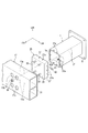
- FIG. 1 is a perspective view of a lower part of a vehicle body provided with an energy absorbing structure according to the first embodiment of the present invention.
- FIG. 2 is a side view including a partial cross section around the energy absorbing structure of FIG.
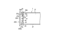
- FIG. 3 is an exploded perspective view around the energy absorbing structure of FIG. 4 is a perspective view of the energy absorbing member in the energy absorbing structure of FIG.
- FIG. 5 is a cross-sectional view showing a state where the energy absorbing member and the connecting member in the energy absorbing structure of FIG. 2 are connected.
- 6 is an operation explanatory diagram showing an initial state in which the energy absorbing member is crushed and deformed with respect to FIG.
- FIG. 7 is a cross-sectional view corresponding to FIG. 5, showing a second embodiment of the present invention.
- FIG. 8 is an operation explanatory view showing an initial state in which the energy absorbing member is deformed by crushing with respect to FIG.
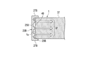
- FIG. 9 is a sectional view showing a third embodiment of the present invention in a state where the energy absorbing member and the connecting member are connected.
- FIG. 10 is a cross-sectional view at a position where the energy absorbing member and the connecting member are rotated 90 degrees with respect to FIG. 9 with the load input direction as an axis.
- FIG. 11 is a perspective view of the energy absorbing member and the connecting member of the third embodiment.
- FIG. 1 shows a lower part of a vehicle body to which an energy absorbing member 1 according to the first embodiment of the present invention is applied.
- the energy absorbing member 1 is a fiber-reinforced resin material configured by impregnating a matrix resin, which is a resin for impregnation, into carbon fibers, which are reinforcing fibers.
- the direction indicated by the arrow FR is the front side of the vehicle body
- the direction indicated by the arrow LH is the left side of the vehicle body
- the direction indicated by the arrow UP is the upper side of the vehicle body.
- the front side member 3 constitutes a skeleton member that forms the skeleton of the vehicle body, bends downward near the position corresponding to the dash panel 5, and is joined to the lower surface of the floor panel 7.
- the dash panel 5 separates the vehicle compartment 9 and the engine compartment 11.
- Side sills 13 are disposed along the vehicle longitudinal direction on both sides of the floor panel 7 in the vehicle width direction, and a hood ridge panel 15 is disposed on the upper side of the front side member 3 on the engine room side.
- the energy absorbing member 1 described above is attached to the front end of the front side member 3.
- a bumper reinforcement 17 is attached to the front end of the energy absorbing member 1 opposite to the front side member 3.
- the bumper reinforcement 17 is disposed along the vehicle width direction, and both ends protrude outward in the vehicle width direction from the energy absorbing member 1.
- a bumper fascia (not shown) is attached to the bumper reinforcement 17.
- the front side member 3 is formed in a quadrangular cylindrical shape, and includes a front end flange 3f at the front end portion on the energy absorbing member 1 side as shown in FIG.
- a rear end flange 1 f is provided at the rear end portion of the energy absorbing member 1 on the front side member 3 side.
- the front end member 3 and the energy absorbing member 1 are fixed by abutting the front end flange 3f and the rear end flange 1f with each other and fastening them with a plurality of bolts 19 and nuts 21.
- the energy absorbing member 1 and the bumper reinforcement 17 are fixed via a connecting member 23.
- the bumper reinforcement 17 and the connecting member 23 constitute a load receiving member.
- the energy absorbing member 1 has a rectangular cylindrical shape like the front side member 3.
- the connecting member 23 is a quadrangle larger than the energy absorbing member 1 when viewed from the front of the vehicle body.
- the connecting member 23 includes an end surface portion 25 that is abutted against the rear surface of the bumper reinforcement 17, and a side wall portion 27 that is bent from four peripheral edges of the end surface portion 25 and protrudes toward the energy absorbing member 1. As shown in FIG. 2, the inner side of the bent portion between the end surface portion 25 and the side wall portion 27 is a concave curved surface portion 29 over the entire circumference.
- the bumper reinforcement 17 is a hollow member whose cross-sectional shape is long in the vertical direction, includes a partition wall 31 at the center in the vertical direction, and a space having a substantially square cross section is formed above and below the partition wall 31.
- Four through holes 17a are provided on the rear surface of the bumper reinforcement 17, and stud bolts 33 are provided on the end surface portion 25 of the connecting member 23 corresponding to the through holes 17a.
- the bumper reinforcement 17 and the connecting member 23 are fixed and integrated by inserting the stud bolt 33 into the through hole 17a and fastening the nut 35 to the stud bolt 33 using the front working hole 17b.
- the connecting member 23 and the energy absorbing member 1 are fixed, they are attached so that the peripheral edge of the front end portion of the energy absorbing member 1 is covered from the outside by the four side walls 27 around the connecting member 23.
- the side wall portion 27 of the connecting member 23 is superimposed on the side surface 37 as the surface portion in the vicinity of the front end portion of the energy absorbing member 1 from the outside to form the overlapping portion 39.
- the side wall portion 27 of the connecting member 23 and the side surface 37 of the energy absorbing member 1 are overlapped in an orthogonal direction intersecting an input direction of an impact load described later.
- a plurality of bolt insertion holes 37a are formed through the side surface 37 of the energy absorbing member 1 in the overlapping portion 39, and a nut 41 is attached inside the side surface 37 around the bolt insertion hole 37a.
- the side wall 27 of the connecting member 23 is formed through the bolt insertion hole 27a.
- the coupling member 23 and the energy absorbing member 1 are fixed by inserting bolts 43 as fasteners into the bolt insertion holes 27 a and 37 a and fastening them to the nuts 41.
- the bolt insertion holes 27 a and 37 a constitute an attachment hole and penetrate the overlapping portion 39 in the overlapping direction.
- a gap 45 is formed between the peripheral front end 1a of the energy absorbing member 1 and the end face portion 25 of the connecting member 23 as shown in FIG.
- the curved surface portion 29 of the connecting member 23 is positioned in front of the peripheral front end 1a of the energy absorbing member 1, and the peripheral front end 1a and the curved surface portion 29 face each other.
- the curved surface portion 29 has an arc shape whose cross-sectional shape is 1/4 of a circle.
- the outer surface of the side surface 37 of the energy absorbing member 1 is substantially located on the tangent line of the arc-shaped end.
- the impact load received by the bumper reinforcement 17 when the automobile collides with the front is transmitted to the energy absorbing member 1 via the connecting member 23. At this time, the energy absorbing member 1 is crushed and deformed between the bumper reinforcement 17 and the front side member 3 to absorb the impact.
- the impact load when the energy absorbing member 1 undergoes crushing deformation is input to the energy absorbing member 1 through a fastening portion by the bolt 43 of the overlapping portion 39.
- the bolt 43 has the shaft part 43a inserted in the bolt insertion holes 27a and 37a. For this reason, the shaft portion 43a of the bolt 43 concentrates stress on the bolt insertion hole 37a with respect to the energy absorbing member 1, and becomes a starting point when the energy absorbing member 1 is crushed.
- Two or three bolts 43 are provided on one side surface 37 of the energy absorbing member 1.
- the impact load applied concentrated on the bolt insertion hole 37 a reaches the side surface 37 of the energy absorbing member 1 for each of the plurality of bolt insertion holes 37 a as indicated by an arrow P. become.
- the energy absorbing member 1 is crushed by an impact load applied to each of the plurality of bolt insertion holes 37a so as to be torn into a plurality along the load input direction starting from the bolt insertion hole 37a. That is, the bolt 43 is provided in the vicinity of the end of the energy absorbing member 1 and functions as a tearing portion that tears the energy absorbing member 1 along the load input direction.
- the connecting member 23 crushes the energy absorbing member 1 and approaches the front side member 3 from the state shown in FIG. 5 before receiving the impact load to the state shown in FIG. Move in the direction. At that time, the energy absorbing member 1 is displaced inward while the peripheral front end 1a is guided by the curved surface portion 29 of the connecting member 23 over the entire circumference to absorb the impact. 5 and 6, the stud bolt 33 similar to the connecting member 23 of FIG. 3 is omitted.
- the energy absorbing member 1 is configured so that the reinforcing fiber 47 indicated by a two-dot chain line extends in a direction intersecting with the load input direction substantially in the same direction as the arrow P, for example, at an angle of approximately 45 degrees. Are arranged.
- the reinforcing fiber 47 is also divided to absorb the impact load. Thereby, the energy absorption efficiency by the energy absorption member 1 increases. 4 and FIG. 11 described later, only a part of the reinforcing fiber 47 is illustrated, but actually, the reinforcing fiber 47 is provided on the entire energy absorbing member 1.
- the bolt 43 that fastens and fixes the energy absorbing member 1 and the connecting member 23 on the bumper reinforcement 17 side constitutes a slit portion that tears the energy absorbing member 1. For this reason, it is not necessary to provide a separate dedicated tearing portion, and the structure can be simplified.
- the energy absorbing member 1 has a cylindrical shape, and the overlapping portion 39 is formed by attaching the side wall portion 27 of the connecting member 23 so as to cover the outer peripheral side of the cylindrical energy absorbing member 1. ing.
- the energy absorbing member 1 is crushed substantially uniformly over the entire circumference with the connecting member 23 by being displaced inward so as to be wrapped from the outside by the side wall portion 27 at the time of crushing.
- the energy absorption efficiency is further increased.
- the energy absorption member 1 can suppress scattering to the outside by being displaced inward and crushed.
- the inside of the bent portion between the end surface portion 25 and the side wall portion 27 of the connecting member 23 is a concave curved surface portion 29.
- the energy absorbing member 1 smoothly displaces inward while the peripheral front end 1a is guided by the curved surface portion 29 of the connecting member 23, and can absorb the impact load more efficiently.
- the energy absorbing member 1 has a prismatic cylindrical shape, and the bolts 43 constituting the tearing portions are provided at positions corresponding to the side surfaces 37 of the energy absorbing member 1 constituted by the prisms.
- stress can be concentrated not only on the corners of the prisms where stress is easily concentrated, but also on the side surfaces 37 which are the surface portions, so that not only the corner portions but also the side surfaces 37 can be torn and crushed.
- the cylindrical energy absorbing member 1 is almost uniformly crushed over the entire circumference, and the energy absorption efficiency is extremely high.
- FIG. 7 and 8 show a second embodiment of the present invention.
- the shape of the connecting member 23A is different from the shape of the connecting member 23 of the first embodiment.
- Other configurations of the energy absorbing member 1 and the like are the same as those of the first embodiment, and the same components are denoted by the same reference numerals and detailed description thereof is omitted.
- the side wall portion 27A is located inside the outer peripheral edge of the end surface portion 25A.
- the end surface portion 25A is provided with a protruding portion 23Aa having an outer peripheral edge protruding outward with respect to the side wall portion 27A.
- the outer side of the bent portion between the side wall portion 27A and the protruding portion 23Aa is a concave curved surface portion 29A over the entire circumference. 7 and 8, the stud bolt 33 similar to the connecting member 23 of FIG. 3 is omitted.
- the rectangular side wall portion 27A is inserted into the energy absorbing member 1. That is, in the present embodiment, contrary to the first embodiment, the side wall portion 27A of the connecting member 23A is superimposed on the side surface 37 near the front end portion of the energy absorbing member 1 from the outside to form the overlapping portion 39A. Is done.
- the curved surface portion 29A of the connecting member 23A is located in front of the peripheral front end 1a of the energy absorbing member 1, and the peripheral front end 1a and the curved surface portion 29A face each other.
- the curved surface portion 29A has an arc shape whose cross-sectional shape is 1/4 of a circle.
- the outer surface of the side surface 37 of the energy absorbing member 1 is substantially located on the tangent line of the arc-shaped end.
- a bolt insertion hole 27Aa is formed so as to correspond to the bolt insertion hole 37a of the energy absorbing member 1.
- a nut 41 is fixed inside the periphery of the bolt insertion hole 27Aa. The connecting member 23A and the energy absorbing member 1 are fixed by inserting the bolt 43 into the bolt insertion holes 37a and 27Aa and fastening the bolt 43 to the nut 41.
- the impact load received by the bumper reinforcement 17 in the state of FIG. 7 is transmitted to the energy absorbing member 1 via the connecting member 23A. At this time, the energy absorbing member 1 is crushed and deformed between the bumper reinforcement 17 and the front side member 3 to absorb the impact.
- the impact load when the energy absorbing member 1 undergoes crushing deformation is input to the energy absorbing member 1 through the fastening portion by the bolt 43 of the overlapping portion 39A, as in the first embodiment.
- the bolt 43 has the shaft portion 43a inserted in the bolt insertion holes 27Aa and 37a. For this reason, the shaft portion 43a of the bolt 43 concentrates stress on the bolt insertion hole 37a, and becomes a starting point when the energy absorbing member 1 is crushed.
- the impact load applied to the bolt insertion hole 37a is a plurality as shown by an arrow P, as in FIG.
- Each bolt insertion hole 37 a reaches the side surface 37 of the energy absorbing member 1.
- the energy absorbing member 1 is crushed by an impact load applied to each of the plurality of bolt insertion holes 37a so as to be torn into a plurality along the load input direction starting from the bolt insertion hole 37a. That is, the shaft portion 43 a of the bolt 43 functions as a tearing portion that tears the energy absorbing member 1.
- the energy absorbing member 1 is located outside the side wall portion 27A of the connecting member 23A.
- the connecting member 23 ⁇ / b> A moves in the direction of approaching the front side member 3 so as to be in the state of FIG. 8 from the state of FIG. 7 before receiving the impact load by crushing the energy absorbing member 1.
- the energy absorbing member 1 is displaced outward while the peripheral front end 1a is guided by the curved surface portion 29A of the connecting member 23A over the entire circumference, and efficiently absorbs the impact.
- the reinforcing fiber 47 indicated by a two-dot chain line has an angle of, for example, approximately 45 degrees with respect to the load input direction substantially in the same direction as the arrow P. It is assumed that they are arranged in the crossing direction. In this case, when the energy absorbing member 1 is torn by the bolt 43 and absorbs the impact load, the reinforcing fiber 47 is also divided to absorb the impact load. Thereby, the energy absorption efficiency by the energy absorption member 1 increases.
- FIG. 9 to 11 show a third embodiment of the present invention.
- the shape of the connecting member 23B is different from the shape of the connecting member 23 of the first embodiment.
- Other configurations of the energy absorbing member 1 and the like are the same as those of the first embodiment, and the same components are denoted by the same reference numerals and detailed description thereof is omitted.
- the connecting member 23B is provided with a plurality of convex portions 49 as slits protruding toward the energy absorbing member 1 inside the end face portion 25B.
- the tip of the convex portion 49 is a convex curved surface.
- the side wall portion 27B is not provided with a bolt insertion hole. 9 to 11, the stud bolt 33 similar to the connecting member 23 of FIG. 3 is omitted.
- the convex portion 49 is located at the inner corner between the end surface portion 25B and the side wall portion 27B, and the tip of the convex curved surface is in contact with the peripheral front end 1a of the energy absorbing member 1.
- Two or three convex portions 49 are provided on one side surface 37 of the energy absorbing member 1.
- the circumferential direction positions of the plurality of convex portions 49 with respect to the energy absorbing member 1 are substantially the same positions as the plurality of bolt insertion holes 37a of the first embodiment.
- the energy absorbing member 1 is in a state where the front end portion is inserted inside the side wall portion 27B of the connecting member 23B, the front edge 1a of the peripheral edge is in contact with the convex portion 49, and the outer peripheral surface is substantially in close contact with the inner surface of the side wall portion 27B Become. In this state, the side wall 27B and the energy absorbing member 1 are bonded and fixed using, for example, an adhesive.
- the convex portion 49 becomes a tearing portion instead of the bolt 43 in the first and second embodiments. Therefore, as shown in FIG. 11, the impact load received by the connecting member 23 ⁇ / b> B is in a state in which stress is concentrated on the peripheral front end 1 a by the plurality of convex portions 49. As a result, the impact load reaches the side surface 37 of the energy absorbing member 1 for each of the plurality of convex portions 49 as indicated by the arrow P. As a result, the energy absorbing member 1 is torn into a plurality along the load input direction starting from the convex portion 49. That is, the convex part 49 functions as a tearing part that tears the energy absorbing member 1.
- the connecting member 23B moves in the direction of approaching the front side member 3 from the state of FIG. 9 before receiving the impact load by crushing the energy absorbing member 1. At that time, the energy absorbing member 1 is displaced inward while being cut to absorb the impact.
- the energy absorbing member 1 has an angle of, for example, approximately 45 degrees with respect to the load input direction in which the reinforcing fiber 47 indicated by a two-dot chain line is substantially the same as the arrow P. It is assumed that they are arranged in the crossing direction. In this case, when the energy absorbing member 1 is cut by the convex portion 49 and absorbs the impact load, the reinforcing fiber 47 is also divided to absorb the impact load. Thereby, the energy absorption efficiency by the energy absorption member 1 increases.
- the side wall portion 27B of the connecting member 23B is attached so as to cover the outer peripheral side of the energy absorbing member 1 as in the first embodiment. For this reason, when the energy absorbing member 1 is crushed from the outside so as to be wrapped from the outside by the side wall portion 27B at the time of crushing, the energy absorbing member 1 is crushed almost uniformly over the entire circumference with the connecting member 23B, and the energy absorption efficiency is It will increase even more. Furthermore, the energy absorption member 1 can suppress scattering to the outside by being displaced inward and crushed.
- 3rd Embodiment replaces with the volt
- connection member 23B and the energy absorption member 1 are being fixed with the adhesive agent, you may fix the surrounding four appropriate places using a volt
- the energy absorbing structure including the energy absorbing member 1 is provided in the front part of the vehicle body.
- the same effect can be obtained even if the energy absorbing structure is provided in the rear part of the vehicle body. Can do.
- the tearing portion constituted by the bolt 43 according to the first and second embodiments and the convex portion 49 according to the third embodiment is provided on the bumper reinforcement 17 side of the energy absorbing member 1.
- a tearing portion may be provided on the front side member 3 side of the energy absorbing member 1 or may be provided on both the bumper reinforcement 17 side and the front side member 3 side.
- the connecting member 23 sets the stud bolt 33 to a position corresponding to the bolt 19 in FIG. 2 and abuts the front end flange 3 f of the front side member 3 to fasten the nut 21 to the stud bolt 33.
- the energy absorbing member 1 does not have the rear end flange 1f shown in FIGS. ,
- the shape of both front and rear ends is made equivalent.
- the structure for attaching the rear end portion of the energy absorbing member 1 to the front side member 3 is the same as the case where the above-described tearing portion is provided only on the front side member 3 side of the energy absorbing member 1.
- the energy absorbing member 1 has a quadrangular cylindrical shape, but a polygonal shape other than the quadrangular prism shape or a cylindrical shape may be used.
- the shapes of the connecting members 23, 23 ⁇ / b> A, and 23 ⁇ / b> B are similarly changed corresponding to the shape of the energy absorbing member 1.
- the energy absorbing member 1 of each embodiment described above is in a direction in which the reinforcing fiber 47 intersects the load input direction in the same direction as the arrow P at an angle of approximately 45 degrees.
- the intersecting angle is not limited to an angle of 45 degrees.
- the reinforcing fibers 47 may intersect at an angle of 90 degrees with respect to the load input direction. In short, it is only necessary that the reinforcing fibers 47 intersect the load input direction substantially in the same direction as the arrow P.
- the reinforcing fiber 47 is cut by the cut portion by crossing the load input direction.
- the first embodiment using the bolts 43 and the third embodiment using the protrusions 49 may be combined.
- the bolts 43 and the convex portions 49 do not overlap along the load input direction.
- the present invention is applied to an energy absorbing structure using an energy absorbing member made of fiber reinforced resin.
Landscapes
- Engineering & Computer Science (AREA)
- Mechanical Engineering (AREA)
- Vibration Dampers (AREA)
- Body Structure For Vehicles (AREA)
Abstract
Description
3 フロントサイドメンバ(骨格部材)
17 バンパレインフォース(荷重受け部材)
23,23A,23B 連結部材(荷重受け部材)
27a,27Aa,37a ボルト挿入孔(取付孔)
37 エネルギ吸収部材の側面(面部)
39,39A 重ね合わせ部
43 ボルト(締結具、切り裂き部)
47 強化繊維
49 凸部(切り裂き部)
Claims (6)
- 車体の骨格を形成する骨格部材と、
前記骨格部材の端部に設けられ、繊維強化樹脂で構成されるエネルギ吸収部材と、
前記エネルギ吸収部材の前記骨格部材と反対側に設けられる荷重受け部材と、
前記荷重受け部材と前記骨格部材との少なくともいずれか一方に対応する前記エネルギ吸収部材の端部付近に設けられ、前記荷重受け部材から前記エネルギ吸収部材に向けて入力した衝撃荷重によって、前記エネルギ吸収部材を切り裂く切り裂き部と、を有し、
前記エネルギ吸収部材において前記衝撃荷重の入力方向に対して交差する方向に延びる強化繊維が、前記エネルギ吸収部材が切り裂かれる際に分断されることを特徴とするエネルギ吸収構造。 - 前記荷重受け部材と前記エネルギ吸収部材とが、前記衝撃荷重の入力方向に対して交差する方向に重ね合わされる重ね合わせ部を有し、
前記重ね合わせ部の重ね合わせ方向に貫通する取付孔が設けられ、
前記取付孔に締結具が挿入されて前記切り裂き部を構成していることを特徴とする請求項1に記載のエネルギ吸収構造。 - 前記エネルギ吸収部材は、筒形状であり、
前記荷重受け部材と前記骨格部材との少なくともいずれか一方が、前記筒形状のエネルギ吸収部材の外周側を覆うように取り付けられることで、前記重ね合わせ部が形成されていることを特徴とする請求項2に記載のエネルギ吸収構造。 - 前記荷重受け部材と前記骨格部材との少なくともいずれか一方の、前記切り裂き部が設けられる側の前記エネルギ吸収部材の端部に対向する部位が、凹状の曲面に形成されていることを特徴とする請求項2または3に記載のエネルギ吸収構造。
- 前記切り裂き部は、
前記荷重受け部材と前記骨格部材との少なくともいずれか一方の前記エネルギ吸収部材に対向する部位に、前記エネルギ吸収部材に向けて突出する凸部が設けられていることを特徴とする請求項1に記載のエネルギ吸収構造。 - 前記エネルギ吸収部材は、角柱の筒形状であり、
前記切り裂き部は、前記角柱の面部に対応する位置に設けられていることを特徴とする請求項1ないし5のいずれか1項に記載のエネルギ吸収構造。
Priority Applications (5)
| Application Number | Priority Date | Filing Date | Title |
|---|---|---|---|
| JP2018511849A JP6569804B2 (ja) | 2016-04-15 | 2016-04-15 | エネルギ吸収構造 |
| US16/093,159 US10710532B2 (en) | 2016-04-15 | 2016-04-15 | Energy absorption structure |
| CN201680084637.0A CN109070820B (zh) | 2016-04-15 | 2016-04-15 | 能量吸收结构 |
| PCT/JP2016/062095 WO2017179187A1 (ja) | 2016-04-15 | 2016-04-15 | エネルギ吸収構造 |
| EP16898647.9A EP3444146B1 (en) | 2016-04-15 | 2016-04-15 | Energy absorption structure |
Applications Claiming Priority (1)
| Application Number | Priority Date | Filing Date | Title |
|---|---|---|---|
| PCT/JP2016/062095 WO2017179187A1 (ja) | 2016-04-15 | 2016-04-15 | エネルギ吸収構造 |
Publications (1)
| Publication Number | Publication Date |
|---|---|
| WO2017179187A1 true WO2017179187A1 (ja) | 2017-10-19 |
Family
ID=60041520
Family Applications (1)
| Application Number | Title | Priority Date | Filing Date |
|---|---|---|---|
| PCT/JP2016/062095 Ceased WO2017179187A1 (ja) | 2016-04-15 | 2016-04-15 | エネルギ吸収構造 |
Country Status (5)
| Country | Link |
|---|---|
| US (1) | US10710532B2 (ja) |
| EP (1) | EP3444146B1 (ja) |
| JP (1) | JP6569804B2 (ja) |
| CN (1) | CN109070820B (ja) |
| WO (1) | WO2017179187A1 (ja) |
Cited By (1)
| Publication number | Priority date | Publication date | Assignee | Title |
|---|---|---|---|---|
| JP2019203572A (ja) * | 2018-05-24 | 2019-11-28 | 三菱重工業株式会社 | 衝撃吸収部材、及び緩衝体 |
Families Citing this family (4)
| Publication number | Priority date | Publication date | Assignee | Title |
|---|---|---|---|---|
| JP6581686B1 (ja) * | 2018-03-30 | 2019-09-25 | 株式会社Uacj | バンパー構造体 |
| FR3116491B1 (fr) * | 2020-11-26 | 2023-03-10 | Valeo Systemes Thermiques | Dispositif absorbeur d’énergie. |
| JP7505510B2 (ja) * | 2022-01-14 | 2024-06-25 | トヨタ自動車株式会社 | 車両構造及び車両の製造方法 |
| CN115370688B (zh) * | 2022-07-25 | 2025-06-20 | 中南大学 | 一种金属圆管的撕裂弯曲式吸能结构 |
Citations (4)
| Publication number | Priority date | Publication date | Assignee | Title |
|---|---|---|---|---|
| JPH05332386A (ja) * | 1992-05-28 | 1993-12-14 | Toyota Autom Loom Works Ltd | エネルギー吸収部材 |
| JP2005247096A (ja) * | 2004-03-03 | 2005-09-15 | Nippon Gmt Kk | 車両用衝撃吸収体及び車両用衝撃吸収装置 |
| WO2014042211A1 (ja) * | 2012-09-13 | 2014-03-20 | 本田技研工業株式会社 | 自動車の車体前部構造 |
| JP2015085788A (ja) * | 2013-10-30 | 2015-05-07 | いすゞ自動車株式会社 | 車両の所定部品の支持構造 |
Family Cites Families (12)
| Publication number | Priority date | Publication date | Assignee | Title |
|---|---|---|---|---|
| DE4425829C1 (de) * | 1994-07-21 | 1995-10-12 | Daimler Benz Aerospace Ag | Strukturelement im Sandwich-Form |
| DE19623449A1 (de) * | 1996-06-12 | 1998-01-02 | Daimler Benz Ag | Stoßenergie absorbierendes Rohrelement |
| US5914163A (en) * | 1997-10-10 | 1999-06-22 | General Motors Corporation | Reduced crush initiation force composite tube |
| US6601886B1 (en) * | 2002-05-31 | 2003-08-05 | Hexcel Corporation | Energy absorbing composite tube |
| DE10243460A1 (de) * | 2002-09-19 | 2004-04-01 | Rehau Ag + Co. | Polymerer Energieabsorber für Kraftfahrzeuge und Stoßfängersystem |
| NO20032896D0 (no) * | 2003-06-23 | 2003-06-23 | Norsk Hydro As | Energiabsorberende system |
| JP4440683B2 (ja) | 2004-03-26 | 2010-03-24 | 日産自動車株式会社 | 繊維強化プラスチック製エネルギー吸収部材の取付け構造 |
| EP2511141B1 (en) * | 2011-04-13 | 2014-01-22 | Volvo Car Corporation | Collision energy absorbing device and a method for controlling energy imparted to a vehicle during a collision |
| DE102012200410A1 (de) * | 2012-01-12 | 2013-07-18 | Thermoplast Composite Gmbh | Energie absorbierende Tragstruktur sowie Verfahren zur Herstellung von dieser |
| DE102012214751A1 (de) * | 2012-08-20 | 2014-06-05 | Bayerische Motoren Werke Aktiengesellschaft | Fahrzeug |
| DE102013200678A1 (de) * | 2013-01-17 | 2014-07-17 | Bayerische Motoren Werke Aktiengesellschaft | Energieaufnahmestruktur für ein Fahrzeug |
| CN104691467B (zh) * | 2015-01-06 | 2016-11-02 | 华侨大学 | 碰撞复合吸能装置和用途 |
-
2016
- 2016-04-15 WO PCT/JP2016/062095 patent/WO2017179187A1/ja not_active Ceased
- 2016-04-15 US US16/093,159 patent/US10710532B2/en active Active
- 2016-04-15 EP EP16898647.9A patent/EP3444146B1/en active Active
- 2016-04-15 CN CN201680084637.0A patent/CN109070820B/zh active Active
- 2016-04-15 JP JP2018511849A patent/JP6569804B2/ja active Active
Patent Citations (4)
| Publication number | Priority date | Publication date | Assignee | Title |
|---|---|---|---|---|
| JPH05332386A (ja) * | 1992-05-28 | 1993-12-14 | Toyota Autom Loom Works Ltd | エネルギー吸収部材 |
| JP2005247096A (ja) * | 2004-03-03 | 2005-09-15 | Nippon Gmt Kk | 車両用衝撃吸収体及び車両用衝撃吸収装置 |
| WO2014042211A1 (ja) * | 2012-09-13 | 2014-03-20 | 本田技研工業株式会社 | 自動車の車体前部構造 |
| JP2015085788A (ja) * | 2013-10-30 | 2015-05-07 | いすゞ自動車株式会社 | 車両の所定部品の支持構造 |
Cited By (2)
| Publication number | Priority date | Publication date | Assignee | Title |
|---|---|---|---|---|
| JP2019203572A (ja) * | 2018-05-24 | 2019-11-28 | 三菱重工業株式会社 | 衝撃吸収部材、及び緩衝体 |
| JP7065689B2 (ja) | 2018-05-24 | 2022-05-12 | 三菱重工業株式会社 | 衝撃吸収部材、及び緩衝体 |
Also Published As
| Publication number | Publication date |
|---|---|
| US10710532B2 (en) | 2020-07-14 |
| EP3444146A1 (en) | 2019-02-20 |
| US20190135210A1 (en) | 2019-05-09 |
| EP3444146A4 (en) | 2019-02-20 |
| JPWO2017179187A1 (ja) | 2019-02-21 |
| JP6569804B2 (ja) | 2019-09-04 |
| CN109070820A (zh) | 2018-12-21 |
| EP3444146B1 (en) | 2020-04-08 |
| CN109070820B (zh) | 2021-07-06 |
Similar Documents
| Publication | Publication Date | Title |
|---|---|---|
| JP6569804B2 (ja) | エネルギ吸収構造 | |
| JP5924334B2 (ja) | 異種材料の接合構造 | |
| JP5983583B2 (ja) | 車両の骨格構造 | |
| CN105882763B (zh) | 车辆用前围板部结构 | |
| JP6206387B2 (ja) | 車両用バックドアの接合方法 | |
| JP5954312B2 (ja) | 車両前部構造 | |
| JP6562064B2 (ja) | 車両の衝撃吸収構造 | |
| JP5862555B2 (ja) | 自動車の車体構造 | |
| JP2014240231A (ja) | 車体前部構造 | |
| JP2014080117A (ja) | 車両用電池搭載構造 | |
| JP2015209111A (ja) | 車両前部構造 | |
| CN111629921A (zh) | 冲击吸收部件 | |
| JP2018100055A (ja) | エネルギ吸収構造 | |
| JP6070481B2 (ja) | 接合構造 | |
| WO2015146903A1 (ja) | 車体側部構造 | |
| JP2001191955A (ja) | 自動車のカウルサイド部への補強構造 | |
| JP5802598B2 (ja) | 車両 | |
| JP6102817B2 (ja) | 車両後部構造 | |
| JP5093094B2 (ja) | ダッシュパネルとトンネル部との結合部構造 | |
| JP5644460B2 (ja) | バンパリインフォースメントと衝撃吸収部材との連結構造 | |
| CN105966463B (zh) | 车身前部结构 | |
| JP5251262B2 (ja) | 車両用フード構造 | |
| US20190126869A1 (en) | Energy absorbing structure | |
| JP6191469B2 (ja) | 車体の部材締結構造 | |
| JP4973045B2 (ja) | 車両前部構造 |
Legal Events
| Date | Code | Title | Description |
|---|---|---|---|
| ENP | Entry into the national phase |
Ref document number: 2018511849 Country of ref document: JP Kind code of ref document: A |
|
| NENP | Non-entry into the national phase |
Ref country code: DE |
|
| WWE | Wipo information: entry into national phase |
Ref document number: 2016898647 Country of ref document: EP |
|
| ENP | Entry into the national phase |
Ref document number: 2016898647 Country of ref document: EP Effective date: 20181115 |
|
| 121 | Ep: the epo has been informed by wipo that ep was designated in this application |
Ref document number: 16898647 Country of ref document: EP Kind code of ref document: A1 |