WO2017179277A1 - フィルタ再生システム、ecu及びフィルタ再生プログラム - Google Patents
フィルタ再生システム、ecu及びフィルタ再生プログラム Download PDFInfo
- Publication number
- WO2017179277A1 WO2017179277A1 PCT/JP2017/004656 JP2017004656W WO2017179277A1 WO 2017179277 A1 WO2017179277 A1 WO 2017179277A1 JP 2017004656 W JP2017004656 W JP 2017004656W WO 2017179277 A1 WO2017179277 A1 WO 2017179277A1
- Authority
- WO
- WIPO (PCT)
- Prior art keywords
- remaining
- soot
- dpf
- amount
- time
- Prior art date
- Legal status (The legal status is an assumption and is not a legal conclusion. Google has not performed a legal analysis and makes no representation as to the accuracy of the status listed.)
- Ceased
Links
Images


Classifications
-
- F—MECHANICAL ENGINEERING; LIGHTING; HEATING; WEAPONS; BLASTING
- F01—MACHINES OR ENGINES IN GENERAL; ENGINE PLANTS IN GENERAL; STEAM ENGINES
- F01N—GAS-FLOW SILENCERS OR EXHAUST APPARATUS FOR MACHINES OR ENGINES IN GENERAL; GAS-FLOW SILENCERS OR EXHAUST APPARATUS FOR INTERNAL-COMBUSTION ENGINES
- F01N3/00—Exhaust or silencing apparatus having means for purifying, rendering innocuous, or otherwise treating exhaust
- F01N3/02—Exhaust or silencing apparatus having means for purifying, rendering innocuous, or otherwise treating exhaust for cooling, or for removing solid constituents of, exhaust
- F01N3/021—Exhaust or silencing apparatus having means for purifying, rendering innocuous, or otherwise treating exhaust for cooling, or for removing solid constituents of, exhaust by means of filters
- F01N3/023—Exhaust or silencing apparatus having means for purifying, rendering innocuous, or otherwise treating exhaust for cooling, or for removing solid constituents of, exhaust by means of filters using means for regenerating the filters, e.g. by burning trapped particles
-
- F—MECHANICAL ENGINEERING; LIGHTING; HEATING; WEAPONS; BLASTING
- F01—MACHINES OR ENGINES IN GENERAL; ENGINE PLANTS IN GENERAL; STEAM ENGINES
- F01N—GAS-FLOW SILENCERS OR EXHAUST APPARATUS FOR MACHINES OR ENGINES IN GENERAL; GAS-FLOW SILENCERS OR EXHAUST APPARATUS FOR INTERNAL-COMBUSTION ENGINES
- F01N9/00—Electrical control of exhaust gas treating apparatus
- F01N9/002—Electrical control of exhaust gas treating apparatus of filter regeneration
-
- F—MECHANICAL ENGINEERING; LIGHTING; HEATING; WEAPONS; BLASTING
- F01—MACHINES OR ENGINES IN GENERAL; ENGINE PLANTS IN GENERAL; STEAM ENGINES
- F01N—GAS-FLOW SILENCERS OR EXHAUST APPARATUS FOR MACHINES OR ENGINES IN GENERAL; GAS-FLOW SILENCERS OR EXHAUST APPARATUS FOR INTERNAL-COMBUSTION ENGINES
- F01N2900/00—Details of electrical control or of the monitoring of the exhaust gas treating apparatus
- F01N2900/06—Parameters used for exhaust control or diagnosing
- F01N2900/14—Parameters used for exhaust control or diagnosing said parameters being related to the exhaust gas
- F01N2900/1404—Exhaust gas temperature
-
- F—MECHANICAL ENGINEERING; LIGHTING; HEATING; WEAPONS; BLASTING
- F01—MACHINES OR ENGINES IN GENERAL; ENGINE PLANTS IN GENERAL; STEAM ENGINES
- F01N—GAS-FLOW SILENCERS OR EXHAUST APPARATUS FOR MACHINES OR ENGINES IN GENERAL; GAS-FLOW SILENCERS OR EXHAUST APPARATUS FOR INTERNAL-COMBUSTION ENGINES
- F01N2900/00—Details of electrical control or of the monitoring of the exhaust gas treating apparatus
- F01N2900/06—Parameters used for exhaust control or diagnosing
- F01N2900/14—Parameters used for exhaust control or diagnosing said parameters being related to the exhaust gas
- F01N2900/1406—Exhaust gas pressure
-
- F—MECHANICAL ENGINEERING; LIGHTING; HEATING; WEAPONS; BLASTING
- F01—MACHINES OR ENGINES IN GENERAL; ENGINE PLANTS IN GENERAL; STEAM ENGINES
- F01N—GAS-FLOW SILENCERS OR EXHAUST APPARATUS FOR MACHINES OR ENGINES IN GENERAL; GAS-FLOW SILENCERS OR EXHAUST APPARATUS FOR INTERNAL-COMBUSTION ENGINES
- F01N2900/00—Details of electrical control or of the monitoring of the exhaust gas treating apparatus
- F01N2900/06—Parameters used for exhaust control or diagnosing
- F01N2900/14—Parameters used for exhaust control or diagnosing said parameters being related to the exhaust gas
- F01N2900/1411—Exhaust gas flow rate, e.g. mass flow rate or volumetric flow rate
-
- F—MECHANICAL ENGINEERING; LIGHTING; HEATING; WEAPONS; BLASTING
- F01—MACHINES OR ENGINES IN GENERAL; ENGINE PLANTS IN GENERAL; STEAM ENGINES
- F01N—GAS-FLOW SILENCERS OR EXHAUST APPARATUS FOR MACHINES OR ENGINES IN GENERAL; GAS-FLOW SILENCERS OR EXHAUST APPARATUS FOR INTERNAL-COMBUSTION ENGINES
- F01N2900/00—Details of electrical control or of the monitoring of the exhaust gas treating apparatus
- F01N2900/06—Parameters used for exhaust control or diagnosing
- F01N2900/16—Parameters used for exhaust control or diagnosing said parameters being related to the exhaust apparatus, e.g. particulate filter or catalyst
- F01N2900/1602—Temperature of exhaust gas apparatus
-
- F—MECHANICAL ENGINEERING; LIGHTING; HEATING; WEAPONS; BLASTING
- F01—MACHINES OR ENGINES IN GENERAL; ENGINE PLANTS IN GENERAL; STEAM ENGINES
- F01N—GAS-FLOW SILENCERS OR EXHAUST APPARATUS FOR MACHINES OR ENGINES IN GENERAL; GAS-FLOW SILENCERS OR EXHAUST APPARATUS FOR INTERNAL-COMBUSTION ENGINES
- F01N2900/00—Details of electrical control or of the monitoring of the exhaust gas treating apparatus
- F01N2900/06—Parameters used for exhaust control or diagnosing
- F01N2900/16—Parameters used for exhaust control or diagnosing said parameters being related to the exhaust apparatus, e.g. particulate filter or catalyst
- F01N2900/1606—Particle filter loading or soot amount
-
- Y—GENERAL TAGGING OF NEW TECHNOLOGICAL DEVELOPMENTS; GENERAL TAGGING OF CROSS-SECTIONAL TECHNOLOGIES SPANNING OVER SEVERAL SECTIONS OF THE IPC; TECHNICAL SUBJECTS COVERED BY FORMER USPC CROSS-REFERENCE ART COLLECTIONS [XRACs] AND DIGESTS
- Y02—TECHNOLOGIES OR APPLICATIONS FOR MITIGATION OR ADAPTATION AGAINST CLIMATE CHANGE
- Y02T—CLIMATE CHANGE MITIGATION TECHNOLOGIES RELATED TO TRANSPORTATION
- Y02T10/00—Road transport of goods or passengers
- Y02T10/10—Internal combustion engine [ICE] based vehicles
- Y02T10/40—Engine management systems
Definitions
- the present invention relates to a filter regeneration system, an ECU, and a filter regeneration program, and is particularly suitable for application to a filter regeneration system, an ECU, and a filter regeneration program that display a predicted regeneration remaining time of a filter.
- DPF diesel particulate filter
- PM particulate matter contained in exhaust gas of an internal combustion engine
- a vehicle equipped with a DPF performs DPF regeneration in which DPF is combusted and regenerated by a heater or the like (particularly soot of PM is combusted) in order to prevent functional degradation due to filter clogging. Kite is also called soot.
- This DPF regeneration is automatically started during traveling under the control of an engine control unit (ECU) that controls the engine. In addition, when regeneration during running is insufficient, it may be started by a driver's switch operation when the vehicle is stopped.
- ECU engine control unit
- the DPF system calculates in advance a time that is a standard for ending the DPF regeneration, and terminates the DPF regeneration based on the calculated time.
- the reference time for completing the DPF regeneration is used only by the ECU for controlling the DPF regeneration, and is not notified to the driver. Accordingly, the driver cannot know the approximate time for ending the DPF regeneration, and cannot make an efficient travel plan with DPF regeneration in mind.
- an object of the present invention is to propose a filter regeneration system, an ECU, and a filter regeneration program that can make an efficient travel plan to the driver by notifying the estimated regeneration remaining time of the DPF.
- the present invention provides a DPF filter regeneration system that collects particulate matter, and includes an ECU that controls the regeneration process of the DPF filter.
- the present soot remaining amount (Rp) is calculated based on the model, and the present soot remaining amount (Rt) is calculated based on a theoretical time model indicating the remaining soot amount, whichever is larger.
- the current estimated DPF regeneration remaining time (Tp, Tt) is calculated, and the estimated remaining DPF regeneration time (Tp, Tt) is notified to the driver.
- FIG. 1 is an overall configuration diagram of a filter regeneration system. It is an internal block diagram of ECU. It is a flowchart of DPF regeneration prediction remaining time calculation processing. It is a flowchart of DPF regeneration prediction remaining time calculation processing at the time of DPF regeneration. It is a conceptual diagram of a physical model. It is a conceptual diagram of a display model. It is a conceptual diagram of a time model.
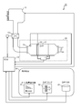
- FIG. 1 is an overall configuration diagram of the filter regeneration system 10.
- the filter regeneration system 10 includes an engine 11 serving as a power source of the vehicle, an ECU 12 that controls the engine 11, a post-processing device 20 that processes exhaust gas exhausted from the engine 11, and vehicle information obtained from the ECU 12. And an in-vehicle instrument 30 to be displayed to the person.
- the post-processing device 20 acquires a DPF 21 that performs post-processing of the exhaust gas from the engine 11, a temperature sensor 22 that acquires the temperature T EXH of the exhaust gas flowing into the DPF 21, and a flow rate M EXH of the exhaust gas that flows into the DPF 21 And a pressure sensor 24 for detecting a differential pressure P EXH between the exhaust gas upstream of the DPF and the exhaust gas downstream of the DPF.
- the in-vehicle instrument 30 is operated by judging from the soot remaining amount display unit 31 that displays the accumulated soot accumulation amount or the remaining amount of soot, the DPF lamp 32 that informs the driver of the DPF state by blinking or lighting, and the state of the DPF lamp. And a DPF switch 33 operated by a person. When the driver operates the DPF switch 33 and instructs the ECU 12 to start DPF regeneration, the ECU 12 instructs the engine 11 to start DPF regeneration.
- the soot remaining amount display unit 31 may indicate the remaining amount of soot by arranging a plurality of bars having different lengths as shown in FIG. 7 described later, or may display the remaining time. Further, the scheduled end time may be displayed by referring to the current time. The soot remaining amount display unit 31 is instructed from a display instruction unit 120E described later.
- the ECU 12 is connected to the engine 11 and the aftertreatment device 20, and is predetermined based on information acquired from the aftertreatment device 20 (temperature T EXH of exhaust gas flowing into the DPF 21, flow rate M EXH, and differential pressure P EXH ).
- the accumulated soot accumulation amount or the remaining amount of soot is calculated in the period of.
- the ECU 12 calculates the integrated soot reduction amount that is the combustion amount of soot from the exhaust gas temperature T EXH and the like at a predetermined cycle, and subtracts it from the integrated soot accumulation amount to burn the soot. The remaining amount of soot is calculated.
- the predetermined cycle may be a short cycle that can be displayed as always updated from the driver, such as 20 milliseconds, or the driver can check the update cycle, such as 1 second, 30 seconds, or 1 minute.
- a relatively long cycle may be used.
- two models are defined as a method for calculating the remaining amount of soot.
- One is a physical model that performs calculation at a predetermined cycle as described above, and the other is information obtained from the post-processing device 20 about the remaining amount of soot only at the start of DPF regeneration (the temperature of exhaust gas flowing into the DPF 21).
- the calculated remaining soot amount is decreased in a predetermined period within a predetermined period (a linear relationship between time and the remaining soot amount). It is a time model (based on a predetermined linear function that defines the relationship).
- the predetermined period may be, for example, the time it takes for the remaining soot to run out when running on a congested road (the longest time). It may be the time it takes for the remaining soot to run out when running on a relatively large road such as a main road at legal speed (standard time).
- An arbitrary time such as a value based on an experiment or a calculation result based on each information at the time of starting DPF regeneration from the ECU 12 can be set.
- the exhaust gas flow rate M EXH may not be a value acquired from the flow sensor 23, but may be a value calculated from an intake flow rate measurement value, the opening degree of the EGR valve 13, the engine speed detected from the sensor, and the like. Further, the soot remaining amount may be calculated from the engine load calculated from the engine speed and the fuel ejection amount (indicated value from the ECU 12 to the engine 11).
- the ECU 12 includes a soot remaining amount calculation unit 120A based on a physical model, a soot remaining amount calculation unit 120B based on a time model, and a soot remaining amount based on a physical model or a soot based on a time model.
- Regeneration model selection unit 120C for selecting any calculation result of remaining amount, DPF regeneration prediction remaining time calculation unit 120D for calculating DPF regeneration prediction remaining time based on the selected calculation result, and calculated DPF regeneration prediction remaining
- CPU Central Processing Unit
- the soot remaining amount calculation unit 120A based on the physical model, the soot remaining amount calculation unit 120B based on the time model, the reproduction model selection unit 120C, the DPF regeneration predicted remaining time calculation unit 120D, and the display instruction unit 120E are realized by software and / or hardware.
- DPF regeneration remaining time prediction process ECU12 performs the process as shown in FIG. First, the soot remaining amount calculation unit 120A based on the physical model calculates the accumulated soot accumulation amount or the soot remaining amount (SP11). Next, the DPF regeneration prediction remaining time calculation unit 120D performs DPF regeneration prediction remaining time conversion from the accumulated soot accumulation amount or the soot remaining amount based on the graph shown in FIG. 5 described later, and calculates the DPF regeneration prediction remaining time (SP12). . Finally, the display instruction unit 120E instructs the soot remaining amount display unit 31 of the in-vehicle instrument 30 to display the predicted DPF regeneration remaining time (SP13). These processes (SP11 to SP13) are repeated at a predetermined cycle. The display content instructed by the display instruction unit 120E to the in-vehicle instrument 30 may be an instruction to display not only the estimated DPF regeneration remaining time but also the accumulated soot accumulation amount or the remaining soot amount.
- the ECU 12 performs processing as shown in FIG. 4 at the time of DPF regeneration.
- the soot remaining amount calculation unit 120A based on the physical model calculates the remaining soot amount (Rp) based on the physical model (SP21).
- the soot remaining amount calculation unit 120B based on the time model calculates the soot remaining amount (Rt) based on the time model (SP22).
- the reproduction model selection unit 120C compares the soot remaining amount (Rp) obtained from the physical model with the soot remaining amount (Rt) obtained from the time model, and selects a larger value (the one with the larger soot remaining amount). (SP23).
- the DPF regeneration prediction remaining time calculation unit 120D calculates the DPF regeneration prediction remaining time (Tp or Tt) corresponding to the soot remaining amount (Rp or Rt) selected in step SP23.
- the display instruction unit 120E instructs the in-vehicle instrument 30 to display the estimated DPF regeneration remaining time (Tp or Tt) (SP24, SP25). These processes (SP21 to SP25) are repeated at a predetermined cycle.
- the display content instructed by the display instruction unit 120E to the in-vehicle instrument 30 may be an instruction to display not only the DPF regeneration predicted remaining time (Tp or Tt) but also the soot remaining amount (Rp or Rt).
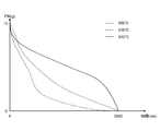
- FIG. 5 is a diagram used by the soot remaining amount calculation unit 120A based on the physical model when calculating the accumulated soot accumulation amount or the soot remaining amount.
- the relationship between the amount of PM for each temperature T EXH of the exhaust gas flowing into the DPF 21 and the time taken to burn the PM when the flow rate M EXH of the exhaust gas to the DPF 21 is constant is shown.
- PM may be regarded as an approximately accumulated soot accumulation amount or a soot remaining amount.
- the case where the temperature T EXH of the exhaust gas flowing into the DPF 21 is 550 ° C. is indicated by a solid line
- the case where it is 600 ° C. is indicated by a broken line
- the case where it is 650 ° C. is indicated by a dotted line.
- a PM amount or an accumulated soot accumulation amount corresponding to the temperature T EXH and the flow rate M EXH of the exhaust gas flowing into the DPF 21 at that time or The soot remaining amount can be obtained.
- the soot remaining amount ratio can be obtained, and the relationship is similar to the physical model indicated by the solid line in FIG.
- the graph of the display model indicated by a thick line in FIG. 6 is a graph of the processing result in FIG.
- the graph based on the physical model is compared with the graph based on the time model, and the graph shows a higher value of the soot remaining ratio axis with respect to the same time axis value. .
- the graph of the display model is the same as the graph of the physical model in the periods S1 and S3, and is the same graph as the time model in the periods S2 and S4. That is, the model with the larger soot remaining ratio is selected as the display model and actually displayed.
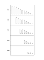
- FIG. 7 is a diagram showing the soot remaining amount calculated by the soot remaining amount calculating unit 120B based on the time model.
- the accumulated soot accumulation amount and a predetermined period based on the accumulated soot accumulation amount are calculated at the start of DPF regeneration (31A), and thereafter, the decrement is performed at a certain rate at a certain time.
- the soot remaining amount is calculated (estimated).
- an example is shown in which not the soot remaining amount but the soot remaining amount ratio compared with the accumulated soot accumulation amount at the start of regeneration and the soot remaining amount is displayed.
- 31A is an image diagram displayed on the soot remaining amount display unit 31 when the soot remaining amount ratio is 100%, and based on only the time model, time elapses at the same intervals as 31A, 31B, 31C, 31D, and 31E. In the case where it goes on, the soot remaining amount ratio decreases with 100%, 80%, 60%, 40%, 20% and the like.
- the soot remaining ratio update cycle is a predetermined cycle.
- the dotted line in FIG. 6 is a graph showing the relationship between the soot remaining amount ratio and time according to the time model.
- the driver can know the estimated time for DPF regeneration to end, and can make an efficient travel plan with DPF regeneration in mind.
- a prediction result which takes more time out of the two models of the physical model and the time model is adopted as a display model, a travel plan with a margin can be made.
- the driver can flexibly change the travel plan according to the scheduled end time displayed at that time. Therefore, an efficient travel plan can be made as a whole.
- the PM amount corresponding to the temperature T EXH and the flow rate M EXH of the exhaust gas that always flows into the DPF 21 at that time in a predetermined cycle in order to use the physical model Or although the soot remaining amount was calculated
- the temperature T EXH and the flow rate M EXH of the exhaust gas flowing into the DPF 21 only for a certain period at the start of regeneration may be confirmed and displayed based on the estimated display model based on those values.
- the traffic situation and legal speed of the road scheduled to travel may be acquired from the car navigation system, and the DPF regeneration prediction remaining time may be calculated based on the information.
Landscapes
- Engineering & Computer Science (AREA)
- Chemical & Material Sciences (AREA)
- Combustion & Propulsion (AREA)
- Mechanical Engineering (AREA)
- General Engineering & Computer Science (AREA)
- Processes For Solid Components From Exhaust (AREA)
- Exhaust Gas After Treatment (AREA)
Abstract
Description
図1は、フィルタ再生システム10の全体構成図である。フィルタ再生システム10は、車両の動力源となるエンジン11と、エンジン11を制御するECU12と、エンジン11から排気される排気ガスを処理する後処理装置20と、車両の情報をECU12から取得し運転者に表示する車内計器30とを備える。
ECU12には、図2に示す通り、物理モデルによるスート残量算出部120Aと、時間モデルによるスート残量算出部120Bと、物理モデルによるスート残量か時間モデルによるスート残量かの何れの算出結果を選択する再生モデル選択部120Cと、選択した算出結果に基づいてDPF再生予測残時間を算出するDPF再生予測残時間算出部120Dと、算出されたDPF再生予測残時間を表示するよう車内計器30に表示指示を行う表示指示部120Eとを備えるCPU(Central Processing Unit)120が含まれている。
ECU12は、図3に示す通りの処理を行う。まず物理モデルによるスート残量算出部120Aは、積算スート堆積量又はスート残量を算出する(SP11)。次にDPF再生予測残時間算出部120Dは、後述の図5に示すグラフに基づく積算スート堆積量又はスート残量からDPF再生予測残時間変換を行い、DPF再生予測残時間を算出する(SP12)。最後に表示指示部120Eは、車内計器30のスート残量表示部31にDPF再生予測残時間の表示を指示する(SP13)。これらの処理(SP11~SP13)を所定の周期で繰り返し行う。なお表示指示部120Eが車内計器30へ指示する表示内容は、DPF再生予測残時間だけではなく、積算スート堆積量又はスート残量の表示を指示してもよい。
以上のように本実施の形態におけるフィルタ再生システム10では、物理モデルと時間モデルの2つのモデルに基づいて、積算堆積量又はスート残量と、DPF再生予測残時間と、DPF再生予測時刻とを車内計器30に表示する。
なお上述の実施の形態においては、スート残量を比較して、物理モデルか時間モデルかを選択する場合を述べたが、DPF再生予測残時間を比較して物理モデルか時間モデルかを選択してもよい。
Claims (6)
- 微粒子状物質を捕集するDPF(21)のフィルタ再生システム(10)において、
前記DPF(21)のフィルタの再生処理を制御するECU(12)を備え、
前記ECU(12)は、
実際のスート残量を示す物理モデルに基づいて、現時点のスート残量(Rp)を算出するとともに理論上のスート残量を示す時間モデルに基づいて、現時点のスート残量(Rt)を算出し、
何れか大きい方のスート残量(Rp、Rt)に基づいて、現時点におけるDPF再生予測残時間(Tp、Tt)を算出し、
前記DPF再生予測残時間(Tp、Tt)を運転者に通知する
フィルタ再生システム。 - 前記ECU(12)は、前記物理モデルに基づいて、
再生の際に所定の周期で、前記DPF(21)に流入する排気ガスの温度を測定する温度センサ(22)からの信号と、前記DPF(21)に流入する排気ガスの流量を測定する流量センサ(23)からの信号とに基づいてスート減少量を算出し、
前記DPF(21)の再生の際に所定の周期で取得する積算スート堆積量から減算することで現時点のスート残量(Rp)を算出する
請求項1に記載のフィルタ再生システム。 - 前記ECU(12)は、前記時間モデルに基づいて、
前記DPF(21)の再生開始の際に取得する積算スート堆積量と、所定の期間とから時間とスート残量との直線的な関係を示す一次関数に基づいて現時点のスート残量(Rt)を算出する
請求項1に記載のフィルタ再生システム。 - 前記ECU(12)は、
車内計器(30)に前記DPF再生予測残時間(Tp、Tt)を表示する
請求項1に記載のフィルタ再生システム。 - 微粒子状物質を捕集するDPF(21)の再生処理を制御するECU(12)において、前記ECU(12)は、
実際のスート残量を示す物理モデルに基づいて、現時点のスート残量(Rp)を算出するとともに理論上のスート残量を示す時間モデルに基づいて、現時点のスート残量(Rt)を算出し、
何れか大きい方のスート残量(Rp、Rt)に基づいて、現時点におけるDPF再生予測残時間(Tp、Tt)を算出し、
前記DPF再生予測残時間(Tp、Tt)を運転者に通知する
ECU。 - 微粒子状物質を捕集するDPF(21)のフィルタ再生プログラムにおいて、
コンピュータに、
実際のスート残量を示す物理モデルに基づいて、現時点のスート残量(Rp)を算出するとともに理論上のスート残量を示す時間モデルに基づいて、現時点のスート残量(Rt)を算出する機能と、
何れか大きい方のスート残量(Rp、Rt)に基づいて、現時点におけるDPF再生予測残時間(Tp、Tt)を算出する機能と、
前記DPF再生予測残時間(Tp、Tt)を運転者に通知する機能と
を実現させるフィルタ再生プログラム。
Priority Applications (6)
| Application Number | Priority Date | Filing Date | Title |
|---|---|---|---|
| ES17782096T ES2794846T3 (es) | 2016-04-11 | 2017-02-09 | Sistema de reproducción de filtro, ECU y programa de reproducción de filtro |
| AU2017248873A AU2017248873A1 (en) | 2016-04-11 | 2017-02-09 | Filter reproduction system, ECU and filter reproduction program |
| CN201780022772.7A CN109072745B (zh) | 2016-04-11 | 2017-02-09 | 过滤器再生系统、ecu及过滤器再生程序模块 |
| JP2018511895A JP6670530B2 (ja) | 2016-04-11 | 2017-02-09 | フィルタ再生システム、ecu及びフィルタ再生プログラム |
| SG11201807958UA SG11201807958UA (en) | 2016-04-11 | 2017-02-09 | Filter regeneration system, ecu, and filter regeneration program |
| EP17782096.6A EP3444455B1 (en) | 2016-04-11 | 2017-02-09 | Filter reproduction system, ecu and filter reproduction program |
Applications Claiming Priority (2)
| Application Number | Priority Date | Filing Date | Title |
|---|---|---|---|
| JP2016078779 | 2016-04-11 | ||
| JP2016-078779 | 2016-04-11 |
Publications (1)
| Publication Number | Publication Date |
|---|---|
| WO2017179277A1 true WO2017179277A1 (ja) | 2017-10-19 |
Family
ID=60042546
Family Applications (1)
| Application Number | Title | Priority Date | Filing Date |
|---|---|---|---|
| PCT/JP2017/004656 Ceased WO2017179277A1 (ja) | 2016-04-11 | 2017-02-09 | フィルタ再生システム、ecu及びフィルタ再生プログラム |
Country Status (8)
| Country | Link |
|---|---|
| EP (1) | EP3444455B1 (ja) |
| JP (1) | JP6670530B2 (ja) |
| CN (1) | CN109072745B (ja) |
| AU (1) | AU2017248873A1 (ja) |
| ES (1) | ES2794846T3 (ja) |
| SG (1) | SG11201807958UA (ja) |
| TW (1) | TWI708890B (ja) |
| WO (1) | WO2017179277A1 (ja) |
Cited By (3)
| Publication number | Priority date | Publication date | Assignee | Title |
|---|---|---|---|---|
| CN110206616A (zh) * | 2019-06-28 | 2019-09-06 | 安徽江淮汽车集团股份有限公司 | 一种颗粒过滤器再生状态的指示方法、装置和系统 |
| CN115898601A (zh) * | 2022-11-21 | 2023-04-04 | 潍柴动力股份有限公司 | 一种颗粒捕集器再生控制方法和相关装置 |
| WO2025142075A1 (ja) * | 2023-12-27 | 2025-07-03 | 株式会社クボタ | 情報表示システム、情報表示方法、コンピュータプログラムおよび作業車両 |
Families Citing this family (4)
| Publication number | Priority date | Publication date | Assignee | Title |
|---|---|---|---|---|
| CN113404575B (zh) * | 2020-03-17 | 2022-11-08 | 联合汽车电子有限公司 | Gpf再生优化方法及gpf再生机会评估系统 |
| CN111810280A (zh) * | 2020-04-26 | 2020-10-23 | 东风商用车有限公司 | Dpf碳载量预警的系统 |
| CN111980791B (zh) * | 2020-09-02 | 2021-10-29 | 潍柴动力股份有限公司 | 一种数据处理方法及系统 |
| CN113448270B (zh) * | 2021-06-24 | 2022-08-30 | 瑞立集团瑞安汽车零部件有限公司 | 一种整车空气处理系统中干燥设备再生控制方法 |
Citations (3)
| Publication number | Priority date | Publication date | Assignee | Title |
|---|---|---|---|---|
| JP2004293413A (ja) * | 2003-03-27 | 2004-10-21 | Isuzu Motors Ltd | 排気ガス浄化システム |
| JP2005133607A (ja) * | 2003-10-29 | 2005-05-26 | Mazda Motor Corp | エンジンの制御装置 |
| JP2011089466A (ja) * | 2009-10-22 | 2011-05-06 | Toyota Industries Corp | ディーゼルエンジンの排気ガス浄化装置 |
Family Cites Families (7)
| Publication number | Priority date | Publication date | Assignee | Title |
|---|---|---|---|---|
| JP4325565B2 (ja) * | 2005-02-10 | 2009-09-02 | 日産自動車株式会社 | 内燃機関の排気浄化装置および排気浄化方法 |
| WO2007136753A2 (en) * | 2006-05-18 | 2007-11-29 | Clean Diesel Technologies, Inc. | Improvements in diesel particulate control |
| FR2966514A3 (fr) * | 2010-10-22 | 2012-04-27 | Renault Sa | Procede de determination des durees des regenerations d'un filtre a particules |
| US9140169B2 (en) * | 2011-11-17 | 2015-09-22 | GM Global Technology Operations LLC | Method for controlling regeneration within an after-treatment component of a compression-ignition engine |
| KR101880307B1 (ko) * | 2011-12-23 | 2018-07-20 | 두산인프라코어 주식회사 | 디젤 미립자 필터의 강제 재생 제어 장치 |
| GB2513586A (en) * | 2013-04-30 | 2014-11-05 | Gm Global Tech Operations Inc | Method of controlling a diesel particulate filter |
| US20150088399A1 (en) * | 2013-09-24 | 2015-03-26 | GM Global Technology Operations LLC | Exhaust system and method of estimating diesel particulate filter soot loading for same |
-
2017
- 2017-02-09 WO PCT/JP2017/004656 patent/WO2017179277A1/ja not_active Ceased
- 2017-02-09 EP EP17782096.6A patent/EP3444455B1/en active Active
- 2017-02-09 SG SG11201807958UA patent/SG11201807958UA/en unknown
- 2017-02-09 TW TW106104262A patent/TWI708890B/zh active
- 2017-02-09 AU AU2017248873A patent/AU2017248873A1/en not_active Abandoned
- 2017-02-09 JP JP2018511895A patent/JP6670530B2/ja active Active
- 2017-02-09 CN CN201780022772.7A patent/CN109072745B/zh active Active
- 2017-02-09 ES ES17782096T patent/ES2794846T3/es active Active
Patent Citations (3)
| Publication number | Priority date | Publication date | Assignee | Title |
|---|---|---|---|---|
| JP2004293413A (ja) * | 2003-03-27 | 2004-10-21 | Isuzu Motors Ltd | 排気ガス浄化システム |
| JP2005133607A (ja) * | 2003-10-29 | 2005-05-26 | Mazda Motor Corp | エンジンの制御装置 |
| JP2011089466A (ja) * | 2009-10-22 | 2011-05-06 | Toyota Industries Corp | ディーゼルエンジンの排気ガス浄化装置 |
Cited By (3)
| Publication number | Priority date | Publication date | Assignee | Title |
|---|---|---|---|---|
| CN110206616A (zh) * | 2019-06-28 | 2019-09-06 | 安徽江淮汽车集团股份有限公司 | 一种颗粒过滤器再生状态的指示方法、装置和系统 |
| CN115898601A (zh) * | 2022-11-21 | 2023-04-04 | 潍柴动力股份有限公司 | 一种颗粒捕集器再生控制方法和相关装置 |
| WO2025142075A1 (ja) * | 2023-12-27 | 2025-07-03 | 株式会社クボタ | 情報表示システム、情報表示方法、コンピュータプログラムおよび作業車両 |
Also Published As
| Publication number | Publication date |
|---|---|
| TW201741546A (zh) | 2017-12-01 |
| CN109072745A (zh) | 2018-12-21 |
| JPWO2017179277A1 (ja) | 2018-11-08 |
| CN109072745B (zh) | 2020-12-22 |
| EP3444455A1 (en) | 2019-02-20 |
| JP6670530B2 (ja) | 2020-03-25 |
| AU2017248873A1 (en) | 2018-10-11 |
| ES2794846T3 (es) | 2020-11-19 |
| EP3444455B1 (en) | 2020-04-08 |
| TWI708890B (zh) | 2020-11-01 |
| EP3444455A4 (en) | 2019-04-24 |
| SG11201807958UA (en) | 2018-10-30 |
Similar Documents
| Publication | Publication Date | Title |
|---|---|---|
| WO2017179277A1 (ja) | フィルタ再生システム、ecu及びフィルタ再生プログラム | |
| CN108252780B (zh) | 机动车辆中微粒过滤器的再生系统及方法 | |
| US11073060B2 (en) | Method for optimizing an active regeneration of a diesel particulate filter | |
| JP5206644B2 (ja) | ディーゼルエンジンの排気ガス浄化装置 | |
| EP1905991A1 (en) | Control method of exhaust gas purification system and exhaust gas purification system | |
| GB2479196A (en) | Method for regenerating a particulate filter using a navigation system | |
| GB2524112A (en) | A control apparatus for optimizing the regeneration of an aftertreatment device | |
| KR20130050999A (ko) | 배기 가스 정화 시스템 및 방법 | |
| JP2008196394A (ja) | 車載内燃機関の排気浄化装置 | |
| WO2011148817A1 (ja) | Dpfシステム | |
| CN105339622A (zh) | 再生过程的时机选择方法 | |
| JP5533259B2 (ja) | 排気ガス浄化システム | |
| CN109838296B (zh) | 具有驾驶者引导功能的颗粒过滤器再生管理方法和系统 | |
| US20060236686A1 (en) | Process for the removal of particulates from the exhaust gas of an internal combustion engine | |
| JP2008202574A (ja) | 車載ディーゼルエンジンの排気浄化装置 | |
| JP2011085096A (ja) | Dpf再生制御装置 | |
| WO2017130408A1 (ja) | 排気浄化装置 | |
| US9115618B2 (en) | Method for the regeneration of a carbon particulate filter | |
| JP5736759B2 (ja) | 内燃機関の排気浄化装置 | |
| JP5613477B2 (ja) | パティキュレートフィルタの再生装置 | |
| EP3153687B1 (en) | Controller for internal combustion engine | |
| JP6132803B2 (ja) | 内燃機関の排ガス浄化装置 | |
| JP2008215218A (ja) | 車載内燃機関の燃料残量警告装置 | |
| JP5799591B2 (ja) | 内燃機関制御装置 | |
| JP4739377B2 (ja) | 微粒子フィルタに蓄積された微粒子の量を決定する方法 |
Legal Events
| Date | Code | Title | Description |
|---|---|---|---|
| WWE | Wipo information: entry into national phase |
Ref document number: 2018511895 Country of ref document: JP |
|
| WWE | Wipo information: entry into national phase |
Ref document number: 11201807958U Country of ref document: SG |
|
| ENP | Entry into the national phase |
Ref document number: 2017248873 Country of ref document: AU Date of ref document: 20170209 Kind code of ref document: A |
|
| NENP | Non-entry into the national phase |
Ref country code: DE |
|
| WWE | Wipo information: entry into national phase |
Ref document number: 2017782096 Country of ref document: EP |
|
| ENP | Entry into the national phase |
Ref document number: 2017782096 Country of ref document: EP Effective date: 20181112 |
|
| 121 | Ep: the epo has been informed by wipo that ep was designated in this application |
Ref document number: 17782096 Country of ref document: EP Kind code of ref document: A1 |