WO2017179453A1 - 検査装置、検査方法 - Google Patents
検査装置、検査方法 Download PDFInfo
- Publication number
- WO2017179453A1 WO2017179453A1 PCT/JP2017/013945 JP2017013945W WO2017179453A1 WO 2017179453 A1 WO2017179453 A1 WO 2017179453A1 JP 2017013945 W JP2017013945 W JP 2017013945W WO 2017179453 A1 WO2017179453 A1 WO 2017179453A1
- Authority
- WO
- WIPO (PCT)
- Prior art keywords
- image
- windshield
- display
- imager
- inspection
- Prior art date
- Legal status (The legal status is an assumption and is not a legal conclusion. Google has not performed a legal analysis and makes no representation as to the accuracy of the status listed.)
- Ceased
Links
Images
Classifications
-
- G—PHYSICS
- G02—OPTICS
- G02B—OPTICAL ELEMENTS, SYSTEMS OR APPARATUS
- G02B27/00—Optical systems or apparatus not provided for by any of the groups G02B1/00 - G02B26/00, G02B30/00
- G02B27/01—Head-up displays
- G02B27/0101—Head-up displays characterised by optical features
- G02B27/0103—Head-up displays characterised by optical features comprising holographic elements
-
- B—PERFORMING OPERATIONS; TRANSPORTING
- B60—VEHICLES IN GENERAL
- B60K—ARRANGEMENT OR MOUNTING OF PROPULSION UNITS OR OF TRANSMISSIONS IN VEHICLES; ARRANGEMENT OR MOUNTING OF PLURAL DIVERSE PRIME-MOVERS IN VEHICLES; AUXILIARY DRIVES FOR VEHICLES; INSTRUMENTATION OR DASHBOARDS FOR VEHICLES; ARRANGEMENTS IN CONNECTION WITH COOLING, AIR INTAKE, GAS EXHAUST OR FUEL SUPPLY OF PROPULSION UNITS IN VEHICLES
- B60K35/00—Instruments specially adapted for vehicles; Arrangement of instruments in or on vehicles
- B60K35/20—Output arrangements, i.e. from vehicle to user, associated with vehicle functions or specially adapted therefor
- B60K35/21—Output arrangements, i.e. from vehicle to user, associated with vehicle functions or specially adapted therefor using visual output, e.g. blinking lights or matrix displays
- B60K35/23—Head-up displays [HUD]
-
- B—PERFORMING OPERATIONS; TRANSPORTING
- B60—VEHICLES IN GENERAL
- B60K—ARRANGEMENT OR MOUNTING OF PROPULSION UNITS OR OF TRANSMISSIONS IN VEHICLES; ARRANGEMENT OR MOUNTING OF PLURAL DIVERSE PRIME-MOVERS IN VEHICLES; AUXILIARY DRIVES FOR VEHICLES; INSTRUMENTATION OR DASHBOARDS FOR VEHICLES; ARRANGEMENTS IN CONNECTION WITH COOLING, AIR INTAKE, GAS EXHAUST OR FUEL SUPPLY OF PROPULSION UNITS IN VEHICLES
- B60K35/00—Instruments specially adapted for vehicles; Arrangement of instruments in or on vehicles
- B60K35/50—Instruments characterised by their means of attachment to or integration in the vehicle
- B60K35/53—Movable instruments, e.g. slidable
-
- B—PERFORMING OPERATIONS; TRANSPORTING
- B60—VEHICLES IN GENERAL
- B60K—ARRANGEMENT OR MOUNTING OF PROPULSION UNITS OR OF TRANSMISSIONS IN VEHICLES; ARRANGEMENT OR MOUNTING OF PLURAL DIVERSE PRIME-MOVERS IN VEHICLES; AUXILIARY DRIVES FOR VEHICLES; INSTRUMENTATION OR DASHBOARDS FOR VEHICLES; ARRANGEMENTS IN CONNECTION WITH COOLING, AIR INTAKE, GAS EXHAUST OR FUEL SUPPLY OF PROPULSION UNITS IN VEHICLES
- B60K35/00—Instruments specially adapted for vehicles; Arrangement of instruments in or on vehicles
- B60K35/80—Arrangements for controlling instruments
- B60K35/81—Arrangements for controlling instruments for controlling displays
-
- B—PERFORMING OPERATIONS; TRANSPORTING
- B60—VEHICLES IN GENERAL
- B60K—ARRANGEMENT OR MOUNTING OF PROPULSION UNITS OR OF TRANSMISSIONS IN VEHICLES; ARRANGEMENT OR MOUNTING OF PLURAL DIVERSE PRIME-MOVERS IN VEHICLES; AUXILIARY DRIVES FOR VEHICLES; INSTRUMENTATION OR DASHBOARDS FOR VEHICLES; ARRANGEMENTS IN CONNECTION WITH COOLING, AIR INTAKE, GAS EXHAUST OR FUEL SUPPLY OF PROPULSION UNITS IN VEHICLES
- B60K35/00—Instruments specially adapted for vehicles; Arrangement of instruments in or on vehicles
- B60K35/90—Calibration of instruments, e.g. setting initial or reference parameters; Testing of instruments, e.g. detecting malfunction
-
- G—PHYSICS
- G01—MEASURING; TESTING
- G01M—TESTING STATIC OR DYNAMIC BALANCE OF MACHINES OR STRUCTURES; TESTING OF STRUCTURES OR APPARATUS, NOT OTHERWISE PROVIDED FOR
- G01M11/00—Testing of optical apparatus; Testing structures by optical methods not otherwise provided for
-
- G—PHYSICS
- G02—OPTICS
- G02B—OPTICAL ELEMENTS, SYSTEMS OR APPARATUS
- G02B27/00—Optical systems or apparatus not provided for by any of the groups G02B1/00 - G02B26/00, G02B30/00
- G02B27/01—Head-up displays
- G02B27/0101—Head-up displays characterised by optical features
-
- B—PERFORMING OPERATIONS; TRANSPORTING
- B60—VEHICLES IN GENERAL
- B60K—ARRANGEMENT OR MOUNTING OF PROPULSION UNITS OR OF TRANSMISSIONS IN VEHICLES; ARRANGEMENT OR MOUNTING OF PLURAL DIVERSE PRIME-MOVERS IN VEHICLES; AUXILIARY DRIVES FOR VEHICLES; INSTRUMENTATION OR DASHBOARDS FOR VEHICLES; ARRANGEMENTS IN CONNECTION WITH COOLING, AIR INTAKE, GAS EXHAUST OR FUEL SUPPLY OF PROPULSION UNITS IN VEHICLES
- B60K2360/00—Indexing scheme associated with groups B60K35/00 or B60K37/00 relating to details of instruments or dashboards
- B60K2360/20—Optical features of instruments
- B60K2360/21—Optical features of instruments using cameras
-
- B—PERFORMING OPERATIONS; TRANSPORTING
- B60—VEHICLES IN GENERAL
- B60K—ARRANGEMENT OR MOUNTING OF PROPULSION UNITS OR OF TRANSMISSIONS IN VEHICLES; ARRANGEMENT OR MOUNTING OF PLURAL DIVERSE PRIME-MOVERS IN VEHICLES; AUXILIARY DRIVES FOR VEHICLES; INSTRUMENTATION OR DASHBOARDS FOR VEHICLES; ARRANGEMENTS IN CONNECTION WITH COOLING, AIR INTAKE, GAS EXHAUST OR FUEL SUPPLY OF PROPULSION UNITS IN VEHICLES
- B60K2360/00—Indexing scheme associated with groups B60K35/00 or B60K37/00 relating to details of instruments or dashboards
- B60K2360/20—Optical features of instruments
- B60K2360/33—Illumination features
- B60K2360/334—Projection means
-
- B—PERFORMING OPERATIONS; TRANSPORTING
- B60—VEHICLES IN GENERAL
- B60K—ARRANGEMENT OR MOUNTING OF PROPULSION UNITS OR OF TRANSMISSIONS IN VEHICLES; ARRANGEMENT OR MOUNTING OF PLURAL DIVERSE PRIME-MOVERS IN VEHICLES; AUXILIARY DRIVES FOR VEHICLES; INSTRUMENTATION OR DASHBOARDS FOR VEHICLES; ARRANGEMENTS IN CONNECTION WITH COOLING, AIR INTAKE, GAS EXHAUST OR FUEL SUPPLY OF PROPULSION UNITS IN VEHICLES
- B60K35/00—Instruments specially adapted for vehicles; Arrangement of instruments in or on vehicles
- B60K35/20—Output arrangements, i.e. from vehicle to user, associated with vehicle functions or specially adapted therefor
- B60K35/21—Output arrangements, i.e. from vehicle to user, associated with vehicle functions or specially adapted therefor using visual output, e.g. blinking lights or matrix displays
- B60K35/23—Head-up displays [HUD]
- B60K35/235—Head-up displays [HUD] with means for detecting the driver's gaze direction or eye points
-
- G—PHYSICS
- G02—OPTICS
- G02B—OPTICAL ELEMENTS, SYSTEMS OR APPARATUS
- G02B27/00—Optical systems or apparatus not provided for by any of the groups G02B1/00 - G02B26/00, G02B30/00
- G02B27/01—Head-up displays
- G02B27/0101—Head-up displays characterised by optical features
- G02B2027/011—Head-up displays characterised by optical features comprising device for correcting geometrical aberrations, distortion
-
- G—PHYSICS
- G02—OPTICS
- G02B—OPTICAL ELEMENTS, SYSTEMS OR APPARATUS
- G02B27/00—Optical systems or apparatus not provided for by any of the groups G02B1/00 - G02B26/00, G02B30/00
- G02B27/01—Head-up displays
- G02B27/0101—Head-up displays characterised by optical features
- G02B2027/0138—Head-up displays characterised by optical features comprising image capture systems, e.g. camera
-
- G—PHYSICS
- G02—OPTICS
- G02B—OPTICAL ELEMENTS, SYSTEMS OR APPARATUS
- G02B27/00—Optical systems or apparatus not provided for by any of the groups G02B1/00 - G02B26/00, G02B30/00
- G02B27/01—Head-up displays
- G02B27/0101—Head-up displays characterised by optical features
- G02B2027/014—Head-up displays characterised by optical features comprising information/image processing systems
Definitions
- the present invention relates to an inspection apparatus and an inspection method.
- a head-up display device (hereinafter referred to as a HUD device) is mounted on a vehicle, enlarges an image generated by a display with a concave mirror and projects it on a windshield of the vehicle, and transmits a virtual image of the image to the driver from inside the vehicle. It is a device that displays in a visible manner. In order to improve the visibility of the virtual image by the driver, it is important to inspect the quality of the final image, which is a virtual image.
- the present invention has been made in view of the above points, and an object of the present invention is to improve the accuracy of inspection in an inspection apparatus that inspects the final image of the HUD apparatus without using a concave mirror.
- the inspection apparatus enlarges the image output from the display with a concave mirror and projects the image onto a windshield of the vehicle, and inspects the virtual image in the head-up display device that displays the virtual image of the image so as to be visible from the inside of the vehicle.
- An inspection apparatus a windshield, a display that generates an image and projects the image onto the windshield without passing through a concave mirror, and an imager that captures a virtual image of the image projected onto the windshield
- storage means for storing preset data of the shape of the windshield and the positional relationship between the windshield, the display device, and the image pickup device, and the image pickup device is moved to a predetermined position.
- the image distortion correction by the concave mirror is calculated, It is a requirement to include display control means for controlling the display so as to generate the image in consideration of image distortion correction, and image inspection means for inspecting distortion of the virtual image picked up by the image pickup device. .
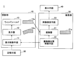
- FIG. 1 is a block diagram showing an example of an inspection apparatus according to the present embodiment.
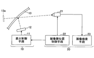
- FIG. 2 is a schematic diagram showing an example of an inspection apparatus according to the present embodiment. However, in FIG. 2, only some of the components of FIG. 1 are illustrated.
- the inspection apparatus 1 includes a projection unit 10, an inspection unit 20, a storage unit 30, and a display unit 40, and a final image of the HUD apparatus without using a concave mirror. It is an apparatus for inspecting the distortion of the image, and a reflection double image can be inspected as necessary.
- the display unit 40 is an option, and the inspection apparatus 1 may not include the display unit 40.
- the inspection apparatus 1 will be described in detail.
- the projection unit 10 includes display control means 11, a display device 12, and a windshield 13.
- the display control means 11 is a means for calculating an image to be displayed on the display 12 and controlling the display 12 to display the calculated image.
- the display control unit 11 is connected to the storage unit 30 and can acquire information necessary for the inspection from the storage unit 30.
- the storage means 30 for example, a semiconductor such as a flash memory, a hard disk, an optical disk, or the like can be used.
- the information necessary for the inspection includes, for example, information on the shape of the windshield 13, information on the positional relationship between the windshield 13 and the HUD device, and information on the optical system in the HUD device.
- the information on the shape of the windshield 13 includes the vertical and lateral curvatures of the windshield 13, the vehicle mounting angle, the cross-sectional shape (flat, wedge shape), and the like.
- the display 12 is a device that generates an image 12 a under the control of the display control means 11 and projects the image 12 a onto the windshield 13.
- the image 12a is directly projected on the windshield 13 without passing through the concave mirror.
- the image 12a may be projected onto the windshield 13 via an optical element that does not cause distortion, such as a plane mirror.
- a liquid crystal panel or the like can be used as the display device 12.
- the image 12a can be, for example, an image that displays an arbitrary geometric shape convenient for inspection as a virtual image.
- a rectangle is displayed as a virtual image.
- the image 12a is an image in which a reverse distortion is intentionally added to the rectangle as shown in FIG.
- the windshield 13 is a member onto which the image 12a generated by the display device 12 is projected.
- the image 12a projected on the windshield 13 becomes visible as a final image 13a (virtual image) from a predetermined position.
- the distortion generated by the windshield 13 and the inverse distortion of the image 12a are offset, and a rectangular final image 13a (virtual image) is visually recognized.
- the inspection unit 20 includes an imager 21, an imager position control unit 22, and an image inspection unit 23.
- the image pickup device 21 is a means for picking up the final image 13a (virtual image) of the image 12a projected on the windshield 13 as a picked-up image 21a.
- the imaging device 21 is configured such that the imaging direction can be adjusted to an arbitrary angle in the horizontal plane and the vertical plane so that the final image 13a can be captured.
- the image pickup device 21 is configured to be movable back and forth, left and right, and up and down. Note that the imaging direction corresponds to the line-of-sight direction of the vehicle driver during actual use.
- a CCD (Charge-Coupled Device) camera or a CMOS (Complementary Metal-Oxide-Semiconductor) camera can be used as the image pickup device 21.
- the imager position control means 22 is a means for controlling the imager 21 to a predetermined position (including an angle).
- the image pickup device position control means 22 controls the image pickup device 21 to a position where the final image 13a can be picked up.
- the display means 40 for example, a liquid crystal display or an organic EL display can be used.
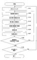
- FIG. 3 is an example of a flowchart showing an inspection method using the inspection apparatus according to the present embodiment.
- the windshield 13 (WS) is set, and the windshield 13 and the display device 12 are brought into a predetermined positional relationship. Since the positional relationship between the windshield 13 and the HUD device in actual use is set for each vehicle type, here the positional relationship between the windshield 13 and the indicator 12 corresponds to the above setting in actual use.
- the windshield 13 is set at a predetermined position.
- the windshield 13 is carried on a belt conveyor, for example, and can be set at a predetermined position using a robot, but is not limited thereto.
- the display 12 may be configured to be movable, and a display moving means for controlling the position of the display 12 may be provided.
- the display device moving means reads the data indicating the positional relationship between the windshield 13 and the display device 12 and the data indicating the positional information of the image pickup device 21 stored in the storage device 30 and reading the data.
- the position of the display 12 is controlled based on the above. Thereby, the position of the display 12 can be finely adjusted so that the windshield 13 set at a predetermined position and the display 12 have a normal positional relationship.
- step S102 the image pickup device position control means 22 moves (positions) the image pickup device 21 to a predetermined position where the final image 13a can be picked up.
- the imager position control unit 22 reads out data indicating the positional relationship between the windshield 13, the display unit 12, and the imager 21 stored in the storage unit 30, and performs imaging based on the read data.
- the position of the vessel 21 is controlled.
- the position where the image pickup device 21 should be disposed corresponds to the driver's viewpoint position during actual use.
- step S103 the display control means 11 is based on the data read from the storage means 30 (that is, the shape of the windshield 13, the windshield 13, the display 12 and the moved image pickup device 21). Based on the positional relationship), in step S102, image distortion correction by the concave mirror corresponding to the position of the image pickup device 21 after movement is calculated, and an image 12a in consideration of the image distortion correction is calculated.
- the display control unit 11 can calculate the image 12a in consideration of image distortion correction, for example, by ray tracing.
- the optical system of the HUD device including the concave mirror has a role of correcting the distortion of the virtual image caused by the shape of the windshield.
- the image distortion correction calculated in step S103 corresponds to the distortion correction by the optical system of the HUD device including the concave mirror.
- the distortion correction value also changes. Therefore, in the inspection apparatus 1, when the position of the image pickup device 21 is moved, it is necessary to newly calculate image distortion correction corresponding to the position of the image pickup device 21 after the movement.
- step S104 the display control means 11 controls the display device 12, and the display device 12 generates an image 12a that takes into account the image distortion correction calculated in step S103, and opens the image 12a without passing through the concave mirror. Project to the shield 13.
- the image 12a is projected onto the windshield 13 and becomes a final image 13a which is a virtual image.
- step S105 the final image 13a (virtual image of the image 12a) projected on the windshield 13 is imaged by the imaging device 21.
- the image inspection unit 23 acquires the information of the captured image 21a and analyzes the received light data for each pixel by image processing, thereby inspecting the distortion of the final image 13a. If necessary, the image inspection means 23 can inspect the reflected double image by analyzing the light reception data for each pixel by image processing.
- step S107 the display unit 40 displays the virtual image and the inspection result of the image inspection unit 23 (distortion and reflection double image graphs and numerical values).
- the inspection of the final image 13a at the position of the image pickup device 21 corresponding to one of the driver's viewpoint positions is completed.
- step S108 the inspection unit 20 determines whether or not to inspect by changing the position of the image pickup device 21.
- the process proceeds to step S102 and the same processing as described above is repeated.
- the position where the light from the display enters the concave mirror changes. That is, when the inspection is performed by changing the position of the image pickup device 21, it is necessary to move the position of the image 12a generated by the display device 12 in accordance with the position of the image pickup device 21 in step S104.
- the display device 12 is large, the image 12a may be moved within the display device 12, but when the display device 12 is small, the display device 12 itself may be moved (including tilting).
- step S109 For example, an input unit for inputting measurement conditions from the outside is provided in the inspection unit 20, and the operator of the inspection apparatus 1 performs the number of inspections in advance (how many imagers 21 are inspected) via the input unit. Enter. Until the inspection unit 20 determines that the number of inspections input from the input unit has been reached, the processing from step S102 to S108 is repeated.
- step S109 the inspection unit 20 determines whether to inspect by changing the windshield 13 (WS) to another WS.
- the process proceeds to step S101 and the same processing as described above is repeated.
- the windshield 13 is changed and inspection is not performed, all inspections are completed.
- an input means for inputting measurement conditions from the outside is provided in the inspection unit 20, and the operator of the inspection apparatus 1 inputs the number of windshields to be inspected in advance. Until the inspection unit 20 determines that the number input from the input means has been reached, the processing from step S101 to S109 is repeated.
- the final image 13a when the driver's viewpoint position changes by inspecting the image pickup device 21 by sequentially changing (moving) the imaging device 21 to different positions. Can be inspected for quality.
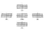
- FIG. 4 is a diagram illustrating an example of an image (virtual image) including distortion generated by the concave mirror when the driver's viewpoint changes.
- the driver's viewpoint position is in the center and when the driver moves in the up-down direction from the center, not much distortion occurs.
- the viewpoint position of the driver moves from the center in the left-right direction, a relatively large distortion of the parallelogram is generated.
- the display control means 11 calculates an image distortion correction corresponding to the position of the image pickup device 21 after the movement. Then, the display 12 generates an image that has been subjected to image distortion correction corresponding to the position of the image pickup device 21 after movement. At this time, the position of the image in the display 12 is moved as necessary. For example, when the image pickup device is at a position corresponding to the center of the driver's line of sight, large distortion does not occur, and when the image pickup device is at a position corresponding to the left and right of the driver's line of sight, FIG. A relatively large distortion of a similar parallelogram shape is generated.
- the description is made on the assumption that the windshield is a windshield, but the present invention is not limited to this, and the windshield may be glass other than the windshield.
Landscapes
- Engineering & Computer Science (AREA)
- Chemical & Material Sciences (AREA)
- Physics & Mathematics (AREA)
- Combustion & Propulsion (AREA)
- Transportation (AREA)
- Mechanical Engineering (AREA)
- General Physics & Mathematics (AREA)
- Optics & Photonics (AREA)
- Analytical Chemistry (AREA)
- Instrument Panels (AREA)
- Testing Of Optical Devices Or Fibers (AREA)
Abstract
Description
図1は、本実施の形態に係る検査装置の一例を示すブロック図である。図2は、本実施の形態に係る検査装置の一例を示す模式図である。但し、図2では、図1の構成要素の一部のみを図示している。
10 投影部
11 表示制御手段
12 表示器
12a 画像
13 ウィンドシールド
13a 最終像
20 検査部
21 撮像器
22 撮像器位置制御手段
23 画像検査手段
30 記憶手段
40 表示手段
Claims (7)
- 表示器から出力した画像を凹面鏡で拡大して車両のウィンドシールドに投影し、前記画像の虚像を前記車両の内部から視認可能に表示させるヘッドアップディスプレイ装置における前記虚像を検査する検査装置であって、
ウィンドシールドと、
画像を生成して、凹面鏡を介さずに前記画像を前記ウィンドシールドに投影する表示器と、
前記ウィンドシールドに投影された前記画像の虚像を撮像する撮像器と、
予め設定された、前記ウィンドシールドの形状と、前記ウィンドシールド、前記表示器、及び、前記撮像器の位置関係と、のデータを格納した記憶手段と、
前記撮像器を所定位置に移動させる撮像器位置制御手段と、
移動後の前記撮像器の位置に対応した前記データに基づいて前記凹面鏡による像歪み補正を計算し、前記像歪み補正を考慮した前記画像を生成するように前記表示器を制御する表示制御手段と、
前記撮像器が撮像した前記虚像の歪みを検査する画像検査手段と、を備える検査装置。 - 前記画像検査手段は、前記撮像器が撮像した前記虚像の歪みを検査すると共に、前記撮像器が撮像した前記虚像の反射二重像を検査する、請求項1に記載の検査装置。
- 前記表示器を所定位置に移動させる表示器移動手段を備える、請求項1又は2に記載の検査装置。
- 前記画像検査手段の検査結果を表示する表示手段を備える、請求項1乃至3の何れか一項に記載の検査装置。
- 前記表示器が生成した前記画像は、前記凹面鏡を含めた光学系を全く介さずに前記ウィンドシールドに直接投影される、請求項1乃至4の何れか一項に記載の検査装置。
- 表示器から出力した画像を凹面鏡で拡大して車両のウィンドシールドに投影し、前記画像の虚像を前記車両の内部から視認可能に表示させるヘッドアップディスプレイ装置における前記虚像を検査する検査方法であって、
ウィンドシールドと表示器を所定の位置関係に配置するステップと、
撮像器を所定位置に移動するステップと、
前記ウィンドシールドの形状と、前記ウィンドシールド、前記表示器、及び、移動後の前記撮像器の位置関係と、に基づいて凹面鏡による像歪み補正を計算するステップと、
前記表示器により、前記像歪み補正を考慮した画像を生成し、凹面鏡を介さずに前記画像を前記ウィンドシールドに投影するステップと、
前記撮像器により、前記ウィンドシールドに投影された前記画像の虚像を撮像するステップと、
前記撮像器が撮像した前記虚像の歪みを検査するステップと、を備えた検査方法。 - 前記撮像器が撮像した前記虚像の反射二重像を検査するステップを備えた、請求項6に記載の検査方法。
Priority Applications (4)
| Application Number | Priority Date | Filing Date | Title |
|---|---|---|---|
| EP17782271.5A EP3444584B1 (en) | 2016-04-14 | 2017-04-03 | Inspecting device and inspecting method |
| JP2018511967A JP6888617B2 (ja) | 2016-04-14 | 2017-04-03 | 検査装置、検査方法 |
| CN201780023124.3A CN109073501B (zh) | 2016-04-14 | 2017-04-03 | 检查装置、检查方法 |
| US16/150,908 US10948719B2 (en) | 2016-04-14 | 2018-10-03 | Inspection device and inspection method |
Applications Claiming Priority (2)
| Application Number | Priority Date | Filing Date | Title |
|---|---|---|---|
| JP2016081531 | 2016-04-14 | ||
| JP2016-081531 | 2016-04-14 |
Related Child Applications (1)
| Application Number | Title | Priority Date | Filing Date |
|---|---|---|---|
| US16/150,908 Continuation US10948719B2 (en) | 2016-04-14 | 2018-10-03 | Inspection device and inspection method |
Publications (1)
| Publication Number | Publication Date |
|---|---|
| WO2017179453A1 true WO2017179453A1 (ja) | 2017-10-19 |
Family
ID=60042111
Family Applications (1)
| Application Number | Title | Priority Date | Filing Date |
|---|---|---|---|
| PCT/JP2017/013945 Ceased WO2017179453A1 (ja) | 2016-04-14 | 2017-04-03 | 検査装置、検査方法 |
Country Status (5)
| Country | Link |
|---|---|
| US (1) | US10948719B2 (ja) |
| EP (1) | EP3444584B1 (ja) |
| JP (1) | JP6888617B2 (ja) |
| CN (1) | CN109073501B (ja) |
| WO (1) | WO2017179453A1 (ja) |
Cited By (7)
| Publication number | Priority date | Publication date | Assignee | Title |
|---|---|---|---|---|
| CN108344562A (zh) * | 2018-03-12 | 2018-07-31 | 福耀集团(上海)汽车玻璃有限公司 | 一种hud前挡玻璃检测设备及方法 |
| EP3620842A1 (de) * | 2018-09-06 | 2020-03-11 | Volkswagen AG | Konzept zum einstellen eines head-up-displays in einem kraftfahrzeug |
| CN111164493A (zh) * | 2018-08-29 | 2020-05-15 | 法国圣戈班玻璃厂 | 用于平视显示器(hud)的检测装置 |
| JP2021015166A (ja) * | 2019-07-10 | 2021-02-12 | マクセル株式会社 | ヘッドアップディスプレイ及びそのキャリブレーション方法 |
| JP2021067528A (ja) * | 2019-10-21 | 2021-04-30 | Agc株式会社 | ガラスの検査装置、ガラスの検査方法 |
| JPWO2023120603A1 (ja) * | 2021-12-21 | 2023-06-29 | ||
| JP2025537899A (ja) * | 2022-11-22 | 2025-11-20 | 福耀玻璃工業集団股▲フン▼有限公司 | 光学素子検出方法、システム及びアプリケーション |
Families Citing this family (9)
| Publication number | Priority date | Publication date | Assignee | Title |
|---|---|---|---|---|
| BR112018076924A2 (pt) * | 2016-07-18 | 2019-04-02 | Saint-Gobain Glass France | sistema de visor head-up para representar informação de imagem para um observador |
| JP6975003B2 (ja) * | 2017-09-29 | 2021-12-01 | 株式会社デンソー | 周辺監視装置およびその校正方法 |
| JP7123403B2 (ja) * | 2019-04-04 | 2022-08-23 | 株式会社Qdレーザ | 画像検査装置 |
| JP7478919B2 (ja) * | 2019-06-27 | 2024-05-08 | パナソニックオートモーティブシステムズ株式会社 | 表示制御装置、画像表示システム、移動体、表示制御方法及びプログラム |
| US20210157135A1 (en) * | 2019-11-26 | 2021-05-27 | GM Global Technology Operations LLC | Head-up display image acquistion and correction |
| WO2022130762A1 (ja) * | 2020-12-15 | 2022-06-23 | Agc株式会社 | 欠陥検査装置、欠陥検査方法および製造方法 |
| CN116204970B (zh) * | 2021-11-30 | 2025-11-11 | 上海汽车集团股份有限公司 | 整车抬头显示系统与前风挡的动态试验方法 |
| KR102979934B1 (ko) * | 2023-09-14 | 2026-06-23 | 주식회사 케이씨씨글라스 | 영상검사장치 및 이를 포함하는 영상검사 시스템 |
| WO2026018108A1 (en) | 2024-07-16 | 2026-01-22 | Sergio FORTE | Automatic inspection system for identifying and evaluating defects on vehicle windscreens |
Citations (9)
| Publication number | Priority date | Publication date | Assignee | Title |
|---|---|---|---|---|
| JPH03505489A (ja) * | 1988-07-01 | 1991-11-28 | ローベルト ボツシユ ゲゼルシヤフト ミツト ベシユレンクテル ハフツング | 自動車のヘツドアツプ表示装置 |
| JPH0640271A (ja) * | 1992-07-23 | 1994-02-15 | Central Glass Co Ltd | 表示装置 |
| US20050219522A1 (en) * | 2004-04-02 | 2005-10-06 | Jones Michael I | System and method for the measurement of optical distortions |
| JP2008209212A (ja) * | 2007-02-26 | 2008-09-11 | Denso Corp | 表示歪み測定装置及び表示歪み補正方法 |
| JP2009262666A (ja) * | 2008-04-23 | 2009-11-12 | Calsonic Kansei Corp | 車両用ヘッドアップディスプレイ装置の調整方法 |
| US8711486B2 (en) * | 2012-06-26 | 2014-04-29 | GM Global Technology Operations LLC | System for highlighting targets on head up displays with near focus plane |
| JP2015087698A (ja) * | 2013-11-01 | 2015-05-07 | Necプラットフォームズ株式会社 | 虚像表示装置 |
| JP2015087512A (ja) * | 2013-10-30 | 2015-05-07 | アイシン・エィ・ダブリュ株式会社 | ヘッドアップディスプレイ装置 |
| WO2015141759A1 (ja) * | 2014-03-20 | 2015-09-24 | 富士フイルム株式会社 | 反射部材、投映スクリーン、コンバイナ、および、遮熱部材 |
Family Cites Families (5)
| Publication number | Priority date | Publication date | Assignee | Title |
|---|---|---|---|---|
| US5422812A (en) | 1985-05-30 | 1995-06-06 | Robert Bosch Gmbh | Enroute vehicle guidance system with heads up display |
| DE102005037797B4 (de) * | 2005-08-03 | 2011-06-01 | Fraunhofer-Gesellschaft zur Förderung der angewandten Forschung e.V. | System und Verfahren zur automatischen Kalibrierung einer Projektion, sowie eine Verwendung des Systems |
| KR101634224B1 (ko) * | 2008-11-05 | 2016-06-28 | 존슨 컨트롤스 게엠베하 | 차량용 디스플레이 시스템 또는 자동차용 투사식 디스플레이, 및 교정 방법 |
| JP6065804B2 (ja) | 2013-10-08 | 2017-01-25 | 株式会社デンソー | 検査装置 |
| JP6370181B2 (ja) * | 2014-09-18 | 2018-08-08 | カルソニックカンセイ株式会社 | 車両用ヘッドアップディスプレイ装置 |
-
2017
- 2017-04-03 WO PCT/JP2017/013945 patent/WO2017179453A1/ja not_active Ceased
- 2017-04-03 EP EP17782271.5A patent/EP3444584B1/en active Active
- 2017-04-03 CN CN201780023124.3A patent/CN109073501B/zh not_active Expired - Fee Related
- 2017-04-03 JP JP2018511967A patent/JP6888617B2/ja active Active
-
2018
- 2018-10-03 US US16/150,908 patent/US10948719B2/en not_active Expired - Fee Related
Patent Citations (9)
| Publication number | Priority date | Publication date | Assignee | Title |
|---|---|---|---|---|
| JPH03505489A (ja) * | 1988-07-01 | 1991-11-28 | ローベルト ボツシユ ゲゼルシヤフト ミツト ベシユレンクテル ハフツング | 自動車のヘツドアツプ表示装置 |
| JPH0640271A (ja) * | 1992-07-23 | 1994-02-15 | Central Glass Co Ltd | 表示装置 |
| US20050219522A1 (en) * | 2004-04-02 | 2005-10-06 | Jones Michael I | System and method for the measurement of optical distortions |
| JP2008209212A (ja) * | 2007-02-26 | 2008-09-11 | Denso Corp | 表示歪み測定装置及び表示歪み補正方法 |
| JP2009262666A (ja) * | 2008-04-23 | 2009-11-12 | Calsonic Kansei Corp | 車両用ヘッドアップディスプレイ装置の調整方法 |
| US8711486B2 (en) * | 2012-06-26 | 2014-04-29 | GM Global Technology Operations LLC | System for highlighting targets on head up displays with near focus plane |
| JP2015087512A (ja) * | 2013-10-30 | 2015-05-07 | アイシン・エィ・ダブリュ株式会社 | ヘッドアップディスプレイ装置 |
| JP2015087698A (ja) * | 2013-11-01 | 2015-05-07 | Necプラットフォームズ株式会社 | 虚像表示装置 |
| WO2015141759A1 (ja) * | 2014-03-20 | 2015-09-24 | 富士フイルム株式会社 | 反射部材、投映スクリーン、コンバイナ、および、遮熱部材 |
Non-Patent Citations (1)
| Title |
|---|
| See also references of EP3444584A4 * |
Cited By (17)
| Publication number | Priority date | Publication date | Assignee | Title |
|---|---|---|---|---|
| CN108344562A (zh) * | 2018-03-12 | 2018-07-31 | 福耀集团(上海)汽车玻璃有限公司 | 一种hud前挡玻璃检测设备及方法 |
| CN108344562B (zh) * | 2018-03-12 | 2023-09-08 | 福耀集团(上海)汽车玻璃有限公司 | 一种hud前挡玻璃检测设备及方法 |
| KR20210038941A (ko) * | 2018-08-29 | 2021-04-08 | 쌩-고벵 글래스 프랑스 | 헤드 업 디스플레이(hud)용 시험 장치 |
| KR102602262B1 (ko) * | 2018-08-29 | 2023-11-14 | 쌩-고벵 글래스 프랑스 | 헤드 업 디스플레이(hud)용 시험 장치 |
| CN111164493A (zh) * | 2018-08-29 | 2020-05-15 | 法国圣戈班玻璃厂 | 用于平视显示器(hud)的检测装置 |
| CN111164493B (zh) * | 2018-08-29 | 2024-12-31 | 法国圣戈班玻璃厂 | 用于平视显示器(hud)的检测装置 |
| JP2021528689A (ja) * | 2018-08-29 | 2021-10-21 | サン−ゴバン グラス フランス | ヘッドアップディスプレイ(hud)のための試験装置 |
| US11340453B2 (en) | 2018-08-29 | 2022-05-24 | Saint-Gobain Glass France | Testing device for a head-up display (HUD) |
| JP7189973B2 (ja) | 2018-08-29 | 2022-12-14 | サン-ゴバン グラス フランス | ヘッドアップディスプレイ(hud)のための試験装置 |
| EP3620842A1 (de) * | 2018-09-06 | 2020-03-11 | Volkswagen AG | Konzept zum einstellen eines head-up-displays in einem kraftfahrzeug |
| JP2021015166A (ja) * | 2019-07-10 | 2021-02-12 | マクセル株式会社 | ヘッドアップディスプレイ及びそのキャリブレーション方法 |
| JP7221161B2 (ja) | 2019-07-10 | 2023-02-13 | マクセル株式会社 | ヘッドアップディスプレイ及びそのキャリブレーション方法 |
| JP7331618B2 (ja) | 2019-10-21 | 2023-08-23 | Agc株式会社 | ガラスの検査装置、ガラスの検査方法 |
| JP2021067528A (ja) * | 2019-10-21 | 2021-04-30 | Agc株式会社 | ガラスの検査装置、ガラスの検査方法 |
| JPWO2023120603A1 (ja) * | 2021-12-21 | 2023-06-29 | ||
| JP7703688B2 (ja) | 2021-12-21 | 2025-07-07 | 京セラ株式会社 | 撮像装置および画像処理方法 |
| JP2025537899A (ja) * | 2022-11-22 | 2025-11-20 | 福耀玻璃工業集団股▲フン▼有限公司 | 光学素子検出方法、システム及びアプリケーション |
Also Published As
| Publication number | Publication date |
|---|---|
| US10948719B2 (en) | 2021-03-16 |
| EP3444584B1 (en) | 2022-02-23 |
| JP6888617B2 (ja) | 2021-06-16 |
| JPWO2017179453A1 (ja) | 2019-03-07 |
| EP3444584A4 (en) | 2019-11-20 |
| US20190033588A1 (en) | 2019-01-31 |
| CN109073501B (zh) | 2021-03-23 |
| CN109073501A (zh) | 2018-12-21 |
| EP3444584A1 (en) | 2019-02-20 |
Similar Documents
| Publication | Publication Date | Title |
|---|---|---|
| JP6888617B2 (ja) | 検査装置、検査方法 | |
| CN102414536B (zh) | 数字光学比较器 | |
| JP4861034B2 (ja) | 車載カメラのキャリブレーションシステム | |
| JP5401940B2 (ja) | 投写光学系のズーム比測定方法、そのズーム比測定方法を用いた投写画像の補正方法及びその補正方法を実行するプロジェクタ | |
| CN112484691B (zh) | 图像处理装置、测距装置、测距方法及记录介质 | |
| US20150189267A1 (en) | Image projection device and calibration method thereof | |
| TWI484283B (zh) | 影像計算量測方法、影像計算量測裝置及影像檢查裝置 | |
| US20090067701A1 (en) | System and method for detecting blemishes on surface of object | |
| JP2005347790A (ja) | 台形歪み補正装置を備えたプロジェクタ | |
| KR101403860B1 (ko) | 웨이퍼표면 검사장치 및 이를 이용한 웨이퍼 표면 검사방법 | |
| JP2004260785A (ja) | 画像歪み補正機能を備えたプロジェクタ装置 | |
| US20140293035A1 (en) | Image processing apparatus, imaging apparatus, microscope system, image processing method, and computer-readable recording medium | |
| WO2014171304A1 (ja) | 撮像装置、撮像装置駆動方法、撮像装置制御プログラム | |
| CN114979418B (zh) | 图像处理装置 | |
| JP2014212462A (ja) | 撮像装置 | |
| US10935500B2 (en) | Welding monitoring system and welding monitoring method | |
| JP5555049B2 (ja) | タイヤ検査装置 | |
| KR101522312B1 (ko) | Pcb 제품 검사 장치 및 이를 이용한 pcb 제품 검사 방법 | |
| KR20170066749A (ko) | 헤드업 디스플레이의 영상 왜곡 보정 장치 및 방법 | |
| JP5531883B2 (ja) | 調整方法 | |
| US20160189422A1 (en) | Process and Device for Determining the 3D Coordinates of an Object | |
| JP2012198306A (ja) | 表示性能測定装置、表示性能測定方法、およびプロジェクター装置 | |
| JP2016170052A (ja) | 目検出装置及び車両用表示システム | |
| US12607851B2 (en) | Method for calibrating, in an automated manner, a virtual retinal scan display for a pair of smart glasses, calibration device, and virtual retinal scan display | |
| WO2020016994A1 (ja) | 画像歪み検査装置、画像歪み検査方法及びプログラム |
Legal Events
| Date | Code | Title | Description |
|---|---|---|---|
| ENP | Entry into the national phase |
Ref document number: 2018511967 Country of ref document: JP Kind code of ref document: A |
|
| NENP | Non-entry into the national phase |
Ref country code: DE |
|
| WWE | Wipo information: entry into national phase |
Ref document number: 2017782271 Country of ref document: EP |
|
| ENP | Entry into the national phase |
Ref document number: 2017782271 Country of ref document: EP Effective date: 20181114 |
|
| 121 | Ep: the epo has been informed by wipo that ep was designated in this application |
Ref document number: 17782271 Country of ref document: EP Kind code of ref document: A1 |