WO2017183073A1 - 手動結束工具 - Google Patents
手動結束工具 Download PDFInfo
- Publication number
- WO2017183073A1 WO2017183073A1 PCT/JP2016/062228 JP2016062228W WO2017183073A1 WO 2017183073 A1 WO2017183073 A1 WO 2017183073A1 JP 2016062228 W JP2016062228 W JP 2016062228W WO 2017183073 A1 WO2017183073 A1 WO 2017183073A1
- Authority
- WO
- WIPO (PCT)
- Prior art keywords
- tool
- band
- binding
- switching
- tightening
- Prior art date
- Legal status (The legal status is an assumption and is not a legal conclusion. Google has not performed a legal analysis and makes no representation as to the accuracy of the status listed.)
- Ceased
Links
Images






Classifications
-
- B—PERFORMING OPERATIONS; TRANSPORTING
- B65—CONVEYING; PACKING; STORING; HANDLING THIN OR FILAMENTARY MATERIAL
- B65B—MACHINES, APPARATUS OR DEVICES FOR, OR METHODS OF, PACKAGING ARTICLES OR MATERIALS; UNPACKING
- B65B13/00—Bundling articles
- B65B13/18—Details of, or auxiliary devices used in, bundling machines or bundling tools
- B65B13/24—Securing ends of binding material
- B65B13/34—Securing ends of binding material by applying separate securing members, e.g. deformable clips
- B65B13/345—Hand tools
-
- B—PERFORMING OPERATIONS; TRANSPORTING
- B65—CONVEYING; PACKING; STORING; HANDLING THIN OR FILAMENTARY MATERIAL
- B65B—MACHINES, APPARATUS OR DEVICES FOR, OR METHODS OF, PACKAGING ARTICLES OR MATERIALS; UNPACKING
- B65B13/00—Bundling articles
- B65B13/02—Applying and securing binding material around articles or groups of articles, e.g. using strings, wires, strips, bands or tapes
- B65B13/025—Hand-held tools
- B65B13/027—Hand-held tools for applying straps having preformed connecting means, e.g. cable ties
-
- B—PERFORMING OPERATIONS; TRANSPORTING
- B65—CONVEYING; PACKING; STORING; HANDLING THIN OR FILAMENTARY MATERIAL
- B65B—MACHINES, APPARATUS OR DEVICES FOR, OR METHODS OF, PACKAGING ARTICLES OR MATERIALS; UNPACKING
- B65B13/00—Bundling articles
- B65B13/18—Details of, or auxiliary devices used in, bundling machines or bundling tools
-
- B—PERFORMING OPERATIONS; TRANSPORTING
- B65—CONVEYING; PACKING; STORING; HANDLING THIN OR FILAMENTARY MATERIAL
- B65B—MACHINES, APPARATUS OR DEVICES FOR, OR METHODS OF, PACKAGING ARTICLES OR MATERIALS; UNPACKING
- B65B13/00—Bundling articles
- B65B13/18—Details of, or auxiliary devices used in, bundling machines or bundling tools
- B65B13/22—Means for controlling tension of binding means
Definitions
- the present invention relates to a manual bundling tool.
- a manual binding tool for example, see Patent Document 1
- This type of manual bundling tool includes a handle and a lever, a tightening mechanism that pulls the band portion after passing through the head portion of the bundling band with respect to the head portion, and the head portion with the distal end side of the band portion as a base end portion. And a cutting mechanism for cutting the band part in the vicinity of the head part.
- the manual binding tool further includes a tightening force adjusting mechanism capable of arbitrarily setting a maximum value of the tightening force by the tightening mechanism.
- the manual bundling tool operates the tightening mechanism until the tightening force by the tightening mechanism reaches a maximum value (set value) when the lever is rotated, and the tightening force is set to a set value. When it reaches, the fixing mechanism and the cutting mechanism are operated in place of the tightening mechanism.
- the operation timing of the push-out mechanism and the cutting mechanism reaches the maximum value set by the tightening force adjusting mechanism when the tightening force by the tightening mechanism is reached by continuing the lever turning operation. It was limited to when. That is, the extrusion mechanism and the cutting mechanism cannot be arbitrarily operated before or after the tightening force by the tightening mechanism reaches the maximum value.
- the binding band when the binding band is tightened so loosely that the bundle of linear members forming the object to be bound is scattered, or when the binding band is tightened so tightly as to damage the object to be bound.
- the tightening force by the tightening mechanism reaches the maximum value, the extrusion mechanism and the cutting mechanism are operated, and there is a possibility that the binding band cannot be properly tightened.
- the present invention has been made in view of such circumstances, and an object of the present invention is to provide a manual binding tool capable of appropriately tightening a binding band.
- Manual binding tool A manual binding tool that can be used for the binding band to bind the objects to be bound by a metal binding band that includes a band-shaped band portion and a head portion provided at one longitudinal end of the band portion. Because A tool body having a housing part, a handle part projecting from the housing part, and a set part formed continuously to the housing part and capable of setting the head part of the binding band; A first operating tool provided to be displaceable with respect to the tool main body so as to face the handle portion; The other end in the longitudinal direction of the band part after passing through the head part set in the setting part can be pulled in a direction away from the head part according to the displacement operation of the first operating tool.
- a tightening mechanism configured as follows: A holding mechanism capable of holding the other end side in the longitudinal direction of the band portion pulled by the tightening mechanism in the tool body so that the band portion does not return and move to the head portion side; A second operating tool provided to be displaceable with respect to the tool body; In response to the displacement operation of the second operating tool, the other end side in the longitudinal direction of the band part passing through the head part already set in the set part is placed on the head part in the longitudinal direction of the band part.
- a fixing mechanism configured to be able to be fixed using A third operating tool provided to be displaceable with respect to the tool body; The other end in the longitudinal direction of the band part after passing through the head part already set in the set part is cut to be separated in the longitudinal direction of the band part according to the displacement operation of the third operating tool.
- a cutting mechanism configured to be able to perform the above operation.
- the tool body has a pistol shape
- the set portion is disposed in an area corresponding to a muzzle portion in the tool body.
- the set part is configured so that the other end in the longitudinal direction of the band part after passing through the head part set in the set part is positioned on the opposite side of the handle part with the housing part interposed therebetween. It is provided in the main body.
- the set part is detachably attached to the housing part.
- the second operation tool and the third operation tool are the same operation tool.
- the second operating tool and the third operating tool are respectively The first operating tool; A switching operation tool for switching a mechanism that operates according to the displacement of the first operation tool between the tightening mechanism, the fixing mechanism, and the cutting mechanism is used.
- the switching operation tool is displaceable integrally with the first operation tool with respect to the tool body so that the switching operation tool can be grasped together with each of the handle portion and the first operation tool, and the first operation tool. Is attached to the first operating tool so as to be relatively displaceable.
- a mechanism for disabling switching by the switching operation tool during displacement of the first operation tool A mechanism for disabling switching by the switching operation tool during displacement of the first operation tool
- FIG. 1 is a perspective view of a manual binding tool according to an embodiment of the present invention.
- FIG. 2 is a side view of the manual binding tool of FIG. 3A is a front view of a binding band used for the manual binding tool of FIG. 1, and
- FIG. 3B is a rear view of the binding band.
- 4A is a longitudinal sectional view of the proximal end side of the binding band of FIG. 3, and
- FIG. 4B is a transverse sectional view of the proximal end side.
- FIG. 5 is a side view of a schematic configuration of the manual binding tool of FIG.
- FIG. 6 is an exploded view of the manual binding tool of FIG.
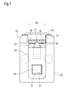
- FIG. 7 is a front view of the distal end portion of the manual binding tool of FIG. FIG.
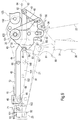
- FIG. 8 is a perspective view when the tightening mechanism in the manual bundling tool of FIG. 1 is in the first state.
- FIG. 9 is a side view when the tightening mechanism of FIG. 8 is in the first state.
- FIG. 10 is a partially enlarged view of FIG.
- FIG. 11 is a side view when the tightening mechanism of FIG. 8 is in the second state.
- FIG. 12 is a partially enlarged view of FIG.
- FIG. 13 is a side view when the fixing mechanism and the cutting mechanism in the manual binding tool of FIG. 1 are each in the first state.
- FIG. 14 is a side view when the fixing mechanism and the cutting mechanism of FIG. 13 are in the second state.
- FIG. 15 is a side view when the fixing mechanism and the cutting mechanism of FIG. 13 are in the third state.
- FIG. 10 is a partially enlarged view of FIG.
- FIG. 11 is a side view when the tightening mechanism of FIG. 8 is in the second state.
- FIG. 12 is a partially
- FIG. 16 is a partially enlarged view of FIG.
- FIG. 17A is a side view showing a state where the set unit in the manual binding tool of FIG. 1 is removed from the housing unit
- FIG. 17B is a front view of a set unit different from the set unit.
- FIG. 18 is a side view when the tightening force adjusting mechanism in the manual binding tool of FIG. 1 is in the first state.
- FIG. 19 is a side view when the tightening force adjusting mechanism of FIG. 18 is in the second state.
- FIG. 20 is a side view when the release mechanism in the manual binding tool of FIG. 1 is in the first state.
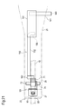
- FIG. 21 is a plan view of the release mechanism of FIG.
- FIG. 22 is a side view when the release mechanism of FIG. 20 is in the second state.
- the arrow X direction in FIG. 1 is the forward direction of the manual binding tool 1
- the arrow Y direction is the upward direction of the manual binding tool 1
- the arrow Z direction is the left direction of the manual binding tool 1. I do.
- the manual binding tool 1 is used to bind a target to be bound (for example, a bundle of linear members 4 such as wiring or piping) 3 with a metal binding band 2. It can be used for the binding band 2.
- the binding band 2 includes a band-shaped band portion 10 and a head portion 11 provided at one end portion (base end portion) 12 in the longitudinal direction of the band portion 10.
- the manual bundling tool 1 is wound around the bundling target 3 and the bundling band 2 is placed on the other end (tip portion) 13 in the longitudinal direction of the band unit 10 after passing through the head unit 11.
- the distal end part 13 side can be fixed to the base end part 12 using the head part 11 so that the band part 10 is kept in a tightened state. It is configured.
- the band portion 10 of the binding band 2 is manufactured using a metal member such as a stainless steel plate, and is predetermined. It is formed in a long shape having a bandwidth of.
- the base end portion 12 of the band portion 10 includes a through hole 14.
- the tip portion 13 of the band portion 10 has a tapered shape.
- the head portion 11 is manufactured using a metal member such as a stainless steel plate, and is formed in a C shape that can be externally fitted to the band portion 10.
- the head portion 11 includes a passage hole 15 through which the band portion 10 can pass, a first opening portion 16 and a second opening portion 17 that are coaxially positioned with the through hole 14, and protrusion portions 18 and 19. Is held by the base end portion 12 of the band portion 10.
- the manual binding tool 1 includes a tool body 20.
- the tool body 20 includes a housing portion 21, a handle portion 22 projecting from the housing portion 21, a continuous connection with the housing portion 21, and the bundling
- the head portion 11 of the band 2 is formed so as to be settable and has a set portion 23.
- the casing portion 21 and the handle portion 22 are configured using a left portion 25 and a right portion 26 that are detachable from each other.
- the casing portion 21 has a hollow shape and extends in the front-rear direction so that the front end (tip end) side is thinner than the front-rear midway portion.
- the handle portion 22 is provided so as to project downward from the front and rear halfway portion of the housing portion 21.
- the handle portion 22 is provided with a grip 24.
- the tool body 20 has a pistol shape, and the set portion 23 is disposed in a region (front end portion) corresponding to a muzzle portion in the tool body 20.
- the set portion 23 is configured such that the head portion 11 can be set so that the tip portion 13 side of the band portion 10 passes through the head portion 11 (the passage hole 15) and protrudes rearward therefrom. ing.
- the set portion 23 includes a fitting portion 27 that can fit the head portion 11 from the front, and the band that protrudes from the head portion 11 fitted to the fitting portion 27. And a guide portion 28 that can guide the tip portion 13 side of the portion 10 backward.
- the guide portion 28 includes a front passage 29 having a width W ⁇ b> 1 so as to pass the tip portion 13 side of the band portion 10, and is disposed behind the fitting portion 27.
- the manual bundling tool 1 includes a first operation tool.
- the first operation tool is provided to be displaceable with respect to the tool body 20 so as to face the handle portion 22 of the tool body 20.
- the first operation tool is a trigger 30 that can be artificially displaced (rotated), and includes a first operation unit 31 and left and right extensions extending from the first operation unit 31. Part 32.
- the trigger 30 extends in the vertical direction.
- the first operation unit 31 is disposed below the housing unit 21 and in front of the handle unit 22.
- the first operation unit 31 is provided with a grip 33.
- the left and right extending portions 32 are generally disposed in the housing portion 21.
- the left and right extending portions 32 are rotatably supported by bushes 35 held by the casing portion 21 at their upper ends.
- the trigger 30 has a non-operating position (a position indicated by a solid line in FIG. 5) in which the first operating portion 31 is separated from the handle portion 22 by a predetermined amount, or the first operating portion 31 is moved from the non-operating position. Also, an operation position (position indicated by a two-dot chain line in FIG. 5) close to the handle portion 22 can be taken. The trigger 30 is held at the non-operation position by the force of the kick spring 36 when not operated.
- the trigger 30 when the trigger 30 is operated against the force of the kick spring 36, the trigger 30 is rotated counterclockwise in FIG. 5 with the bush 35 as a fulcrum so as to take the operation position.
- the trigger 30 is rotated clockwise in FIG. 5 by the force of the kick spring 36 so as to return to the non-operation position.
- the manual bundling tool 1 includes a tightening mechanism 40.
- the tightening mechanism 40 separates the front end portion 13 side of the band portion 10 after passing through the head portion 11 already set in the setting portion 23 with respect to the head portion 11 in accordance with the displacement operation of the trigger 30. It is configured so that it can be pulled in the direction (backward).
- the tightening mechanism 40 is generally provided in the housing portion 21 of the tool main body 20, and is provided between the trigger 30 and the distal end portion of the housing portion 21.
- the tightening mechanism 40 includes a tightening lever 41, a trigger link 42, a link bar 43, a rear chuck bar 44, a front chuck bar 45, and a chuck 46.
- the tightening lever 41 includes left and right plate portions 51 and a connecting portion 52 that connects the left and right plate portions 51.
- the front and rear halfway portions of the left and right plate portions 51 are positioned between the left and right extending portions 32 of the trigger 30, and the connecting portion 52 is located forward of the left and right extending portions 32. It is arranged to be located.
- the left and right plate portions 51 are rotatably supported by the bush 35 at their upper ends.
- long holes 53 are provided so as to extend substantially in the vertical direction.
- a first pin 54 is inserted into the elongated hole 53 so as to be movable along the longitudinal direction of the elongated hole 53.
- the first pin 54 is supported by a lower end portion of a tension slide 121, which will be described later, and is held in the upper portion of the long hole 53 during tightening by the tightening mechanism 40 (see FIG. 18).
- the connecting portion 52 extends between the left and right plate portions 51.
- a recess 55 is provided at the front end of the tightening lever 41 (the front end of each of the left and right plate portions 51 and / or the connecting portion 52) so as to open substantially upward.
- the recess 55 is formed so as to be engageable with the switching pin 85.
- the switching pin 85 can be engaged with and disengaged from the recess 55 according to the operation of the trigger 30.
- the tension lever 41 is held in the state shown in FIG. 5 by the force of the kick spring 56 when the trigger 30 is in the non-operation position.
- the tightening lever 41 receives a force against the force of the kick spring 56 via the switching pin 85 and uses the bush 35 as a fulcrum. 5 is rotated counterclockwise.
- the trigger link 42 includes left and right plate portions 57 and a connecting portion 58 that connects the left and right plate portions 57.
- the trigger link 42 is disposed so that the front portions of the left and right plate portions 57 and the connecting portion 58 are positioned between the left and right plate portions 51 of the tightening lever 41, respectively.
- the left and right plate portions 57 are rotatably supported by the bush 35 at their upper ends.
- the lower portions of the left and right plate portions 57 are each provided with a recess 59 so as to open downward.
- the first pin 54 protruding from the elongated hole 53 in the tightening lever 41 can be engaged with the recess 59.
- the trigger link 42 can rotate about the bush 35 as a fulcrum integrally with the tightening lever 41 by engagement with the pin 54.
- the link bar 43 has a long shape and is provided on the rear side of the trigger link 42.
- the link bar 43 is rotatably connected to the rear lower end portions of the left and right plate portions 57 of the trigger link 42 via a second pin 61 at one longitudinal end portion (front lower end portion).
- the link bar 43 is disposed so as to extend rearward and upward from a connection portion with the trigger link 42.
- the rear chuck bar 44 extends in the front-rear direction, and is rotatable at one longitudinal end portion (rear end portion) via the other longitudinal end portion (rear upper end portion) of the link bar 43 and the third pin 62. It is connected to.
- a cylindrical body 63 is fitted on each of both longitudinal ends of the third pin 62.
- the cylindrical body 63 is supported by a guide groove 64 provided on the inner surface side of the housing portion 21 so as to be capable of reciprocating in the front-rear direction.
- the front chuck bar 45 extends in the front-rear direction, and is connected to the other longitudinal end portion (front end portion) of the rear chuck bar 44 via a fourth pin 65 at one longitudinal end portion (rear end portion). Yes.
- the front chuck bar 45 is disposed so as to extend forward from a connecting portion with the rear chuck bar 44 so that the other end portion in the longitudinal direction (front end portion) is located behind the set portion 23. .
- the front chuck bar 45 can be reciprocated in the front-rear direction integrally with the rear chuck bar 44. That is, the front chuck bar 45 integrally moves rearward as the rear chuck bar 44 moves rearward along the guide groove 64, and the rear chuck bar 44 moves along the guide groove 64. As it moves forward, it can move forward one time.
- the front end of the front chuck bar 45 is positioned immediately behind the set portion 23 (the guide portion 28). It becomes.
- the front chuck bar 45 is located on the rearmost side, the front end portion of the front chuck bar 45 is separated from the set portion 23 by a predetermined amount as shown in FIG.
- the chuck 46 is rotatably supported by a front end portion of the front chuck bar 45 via a fifth pin 66. As shown in FIG. 10, the chuck 46 has a rear passage path 67 formed in the front end portion of the front chuck bar 45 for passing the front end portion 13 side of the band portion 10 after passing through the front passage path 29. As described above, the front chuck bar 45 is disposed at a position facing the front upper end 68.
- the chuck 46 has a claw portion facing the rear passage 67 at the rear upper end.
- the chuck 46 cooperates with a front upper end portion 68 of the front chuck bar 45 by using a claw portion of the chuck 46 and a part on the front end portion 13 side of the band portion 10 passing through the rear passage path 67. Therefore, the kick spring 69 is urged to rotate counterclockwise in FIG.
- the front end portion 13 side of the band portion 10 moves back in the direction (forward direction) through the rear passage 67.
- the tip portion 13 side of the band portion 10 is allowed to advance in the direction opposite to the direction of exiting the rear passage path 67 (rearward direction).
- the chuck 46 rotates against the force of the kick spring 69 when the front end of the front chuck bar 45 is in the foremost position, that is, immediately behind the set portion 23.
- the rear passage 67 is brought into a released state so that the tip portion 13 side of the band portion 10 is movable when hitting the set portion 23 (the guide portion 28).
- the manual bundling tool 1 is also provided with a holding mechanism 70.
- the holding mechanism 70 is configured so that the tip portion 13 side of the band portion 10 pulled by the tightening mechanism 40 does not move back to the head portion 11 side (front side) already set in the set portion 23.
- the tool body 20 can be held.
- the holding mechanism 70 includes a detent chuck 71.
- the detent chuck 71 is rotatably supported on the guide portion 28 of the set portion 23 via a sixth chuck pin 72. As shown in FIG. 10, the detent chuck 71 is provided in front of the chuck 46, and the front passage 29 that can be arranged continuously with the rear passage 67 is formed in the guide portion 28. As described above, the guide portion 28 is disposed at a position facing the upper end portion 73.
- the detent chuck 71 has a claw portion facing the front passage 29 at the rear upper end.
- the detent chuck 71 cooperates with the upper end portion 73 of the guide portion 28 by using a claw portion of the detent chuck 71 to cooperate with the upper end portion 73 of the guide portion 28 on a part of the band portion 10 on the front end portion 13 side. In order to act and pinch, it is urged
- the front end portion 13 side of the band portion 10 moves in a direction (forward direction) through the front passage 29. This is prevented, and the tip portion 13 side of the band portion 10 is allowed to move in the direction (rearward direction) opposite to the direction through the front passage 29.
- the said manual binding tool 1 is also provided with the 2nd operation tool.
- the second operation tool is provided to be displaceable with respect to the tool body 20.
- the second operating tool is configured using the trigger 30 and a switching lever 80 as a switching operating tool that can be artificially displaced (rotated).
- the switching lever 80 is supported by the trigger 30.
- the switching lever 80 switches a mechanism that operates in accordance with the displacement of the trigger 30 between the tightening mechanism 40 and a fixing mechanism 90 described later (in the present embodiment, the fixing mechanism 90 and the cutting mechanism 100). belongs to.
- the switching lever 80 is attached to the trigger 30 so that it can be displaced integrally with the trigger 30 and can be displaced relative to the trigger 30 when displaced.
- the switching lever 80 includes a second operation portion 81 and left and right extending portions 82 extending from the second operation portion 81.
- the switching lever 80 extends substantially in the vertical direction and is provided on the front side of the trigger 30.
- the second operation portion 81 is disposed below the housing portion 21, and the left and right extending portions 82 are disposed in the housing portion 21.
- the switching lever 80 is pivotally connected to the middle part of the trigger 30 via a seventh pin 83 at the middle part.
- the switching pin 85 extends between the upper end portions of the left and right extending portions 82 so that the switching pin 85 can be displaced according to the operation of the switching lever 80 and / or the trigger 30. ing.
- the switching lever 80 includes a first switching operation position where the second operation unit 81 is not displaced with respect to the trigger 30 (see FIGS. 5 and 13), and the second operation unit 81 with respect to the trigger 30.
- the second switching operation position relatively displaced can be taken.
- the switching lever 80 is held at the first switching operation position by the force of the kick spring 86 when not operated.
- the switching lever 80 when the switching lever 80 is operated against the force of the kick spring 86, the switching lever 80 rotates counterclockwise in FIG. 13 with the seventh pin 83 as a fulcrum so as to take the second switching operation position. Be made.
- the switching lever 80 is rotated by the force of the kick spring 86 so as to return to the first switching operation position.
- the switching lever 80 When the switching lever 80 is displaced together with the trigger 30 in the first switching operation position, the switching pin 85 is engaged with the recess 55 of the tightening lever 41 (see FIG. 11). When the trigger 30 is operated against the force of the kick spring 86 in a state where the trigger 30 is in the non-operation position, the switching lever 80 engages the switching pin 85 with a punch lever 91 described later (see FIG. 14). ).
- the manual binding tool 1 is also provided with the fixing mechanism 90.
- the fixing mechanism 90 uses a part of the band portion 10 on the side of the distal end portion 13 side that is passing through the head portion 11 already set in the setting portion 23 as a displacement operation of the switching lever 80 and the trigger 30. Accordingly, the distal end portion 13 side can be fixed to the base end portion 12 of the band portion 10 using the head portion 11.
- the fixing mechanism 90 is generally provided in the front portion of the housing portion 21 of the tool body 20 and is provided between the switching lever 80 and the trigger 30 and the set portion 23.
- the fixing mechanism 90 can operate alternatively to the tightening mechanism 40 by the switching action of the switching lever 80, and includes the punch lever 91, a holder 92, and a punch 93.
- the punch lever 91 has a bent shape that protrudes downward, and is provided to extend in the front-rear direction.
- the punch lever 91 is disposed below the front chuck bar 45 and is rotatably supported by the front portion of the housing portion 21 via an eighth pin 94 at a front and rear halfway portion.
- the eighth pin 94 is disposed in front of the bent portion of the punch lever 91.
- the rear end portion 95 of the punch lever 91 is disposed in the vicinity of the lower portion of the switching pin 85 so as to be engageable with the switching pin 85 provided on the switching lever 80 from below.
- the front end portion 96 of the punch lever 91 is inserted into the insertion hole 97 of the holder 92 so as to engage with the holder 92 disposed in the fitting portion 27 of the set portion 23 (see FIG. 7 and FIG. 7). (See FIG. 10).
- the punch lever 91 is held so as not to engage with the switching pin 85 by the force of the kick spring 98 when the switching lever 80 is in the first switching operation position (see FIG. 13).
- the punch lever 91 engages with the switching pin 85 when receiving a force against the force of the kick spring 98 via the switching pin 85 when the switching lever 80 is in the second switching operation position. (See FIG. 14).
- the punch lever 91 After the engagement with the switching pin 85, the punch lever 91 is rotated clockwise in FIG. 13 with the eighth pin 94 as a fulcrum when the switching lever 80 is operated together with the trigger 30 (FIG. 13). 15). The punch lever 91 cannot be engaged with the switching pin 85 if the trigger 30 is not in the non-operation position when the switching lever 80 moves to the second switching operation position.
- the holder 92 is provided in the fitting portion 27.
- the holder 92 has the insertion hole 97 penetrating the holder 92 in the front-rear direction, and is integrally connected to the front end portion 96 of the punch lever 91 inserted into the insertion hole 97.
- the holder 92 can be displaced in the vertical direction according to the rotation of the punch lever 91 when the front end 96 is inserted into the insertion hole 97.
- the punch 93 protrudes upward from the upper surface of the holder 92 so as to be displaced together with the holder 92 in the vertical direction.
- the punch 93 has a pointed protruding end formed so as to taper upward. From the protruding end, the through hole 14 of the band unit 10 and the first opening of the head unit 11 are formed. 16 and the second opening 17 are formed so as to pass through.
- the punch 93 is a non-deformation position (see FIG. 13) that does not hinder the setting of the head portion 11 to the setting portion 23, or the band portion 10 within the head portion 11 that has been set to the setting portion 23.
- a deformation position (see FIGS. 15 and 16) that sequentially passes through the first opening 16, the through hole 14, and the second opening 17 in order to plastically deform a part on the tip portion 13 side into the convex portion 99 is taken. To get.
- the convex portion 99 formed on the front end portion 13 side of the band portion 10 is engaged with the inner surface of the second opening portion 17 of the head portion 11 in the longitudinal direction (front-rear direction) of the band portion 10. .
- the distal end portion 13 side of the band portion 10 can be fixed to the base end portion 12 side using the head portion 11. ing.
- the manual binding tool 1 is also provided with a third operation tool.
- the third operation tool is provided so as to be displaceable with respect to the tool body 20.
- the third operating tool is the same operating tool as the second operating tool, and includes the trigger 30 and a switching lever 80 that can be artificially displaced (rotated).
- the second operation tool also serves as the third operation tool.
- the manual bundling tool 1 is also provided with the cutting mechanism 100.
- the cutting mechanism 100 moves the tip portion 13 side of the band portion 10 after passing through the head portion 11 set in the setting portion 23 in accordance with the displacement operation of the trigger 30 and the switching lever 80. It is comprised so that it can cut
- the cutting mechanism 100 includes the punch lever 91, the holder 92, and a cutter blade 101.
- the cutter blade 101 protrudes upward from the upper surface of the holder 92 so as to be displaced in the vertical direction together with the holder 92. That is, the cutter blade 101 can be displaced in synchronization with the displacement of the punch 93.
- the cutter blade 101 is disposed behind the punch 93.
- the band portion is at a time later than the operation start time of the punch 93 with respect to the distal end portion 13 side of the band portion 10. It is formed so that the cutting of the front end portion 13 side of 10 can be completed.
- the cutter blade 101 does not cut the front end portion 13 side of the band portion 10 that protrudes rearward from the passage hole 15 of the head portion 11 already set in the setting portion 23 toward the front passage 29.
- a cutting position (see FIG. 13) or a cutting position (see FIG. 15) for cutting the distal end 13 side of the band unit 10 between the head unit 11 and the holding mechanism 70 can be taken. .
- a pre-processing step for attaching the binding band 2 to the manual binding tool 1 and the binding target 3 is performed. That is, the band portion 10 of the binding band 2 is wound around the binding target 3. And the head part 11 of the said binding band 2 is set to the setting part 23 (the said fitting part 27) of the said tool main body 20 in the said manual binding tool 1.
- the band part 10 is passed from the tip part 13 side through the passage hole 15 of the head part 11, the front passage path 29 in the manual bundling tool 1, and the rear passage path 67 in this order, and the tip part 13 side of the band part 10. Is held by the holding mechanism 70. According to the present embodiment, if the work relating to the binding band 2 needs to be performed again, it can be performed using the release mechanism 150 described later.
- the end portion 13 side of the band portion 10 after passing through the rear passage path 67 is pulled in a direction (rearward) away from the head portion 11 by an artificial operation. .
- the movement of the band portion 10 on the distal end portion 13 side is not hindered by the detent chuck 71 in the holding mechanism 70 and the chuck 46 in the tightening mechanism 40 as described above.
- the handle portion 22 and the trigger 30 of the tool main body 20 are gripped, and the trigger 30 is operated to be displaced from the non-operation position shown in FIG. 9 to the operation position shown in FIG.
- the switching lever 80 is displaced together with the trigger 30 in the first switching operation position, so that the switching pin 85 is first displaced rearward so as to engage with the recess 55, and then the recess 55. In the engaged state, it is further displaced rearward. Therefore, the tightening lever 41 is pushed by the switching pin 85 and rotates counterclockwise in FIG. 9 with the bush 35 as a fulcrum.
- Rotation of the tightening lever 41 causes the first pin 54 inserted through the long hole 53 to be displaced rearward. Since the first pin 54 is engaged with the recess 59, the trigger link 42 is pushed by the first pin 54 and rotates counterclockwise in FIG. 9 with the bush 35 as a fulcrum. Therefore, the link bar 43 is displaced so as to move the rear upper end portion rearward along the guide groove 64.
- the rear chuck bar 44 moves rearward due to the displacement of the link bar 43. Accordingly, the front chuck bar 45 moves rearward. Accordingly, the chuck 46 starts to move backward so as to be separated from the set portion 23 so as to grip the tip portion 13 side of the band portion 10 in the rear passage path 67, and subsequently the tip of the band portion 10. It moves further backward while holding the part 13 side.
- the tightening mechanism 40 can pull the tip portion 13 side of the band portion 10 backward with respect to the head portion 11 so as to increase the tightening force of the binding band 2 by a predetermined amount. Then, the trigger 30 is released to return to the original state. As a result, the tightening mechanism 40 returns to its original state so that it can be operated by re-operation of the trigger 30.
- the operation of the trigger 30 is performed at least once until the tightening force of the binding band 2 becomes a desired tightening force.
- the end time of the tightening step may be determined by visually observing the state of the binding band 2, for example.
- the tightening force adjusting mechanism 120 may be used for the determination.
- a fixing step is performed to fix the distal end portion 13 side to the base end portion 12 of the band portion 10 using the fixing mechanism 90. Specifically, first, the handle portion 22 and the switching lever 80 are grasped in a state where the trigger 30 is in the non-operation position, and the switching lever 80 is moved from the first switching operation position shown in FIG. It operates so that it may displace to the said 2nd switching operation position shown.
- the switching pin 85 is engaged with the rear end portion 95 of the punch lever 91 from above so that the mechanism that operates according to the displacement of the trigger 30 is switched. Then, the trigger 30 is further grasped with the switching lever 80 being displaced to the second switching operation position as described above, and is displaced to the operation position together with the switching lever 80 as shown in FIG. To operate.
- the punch lever 91 is pushed by the switching pin 85 and rotates clockwise in FIG. 14 with the eighth pin 94 as a fulcrum. Therefore, the holder 92 is displaced upward. Accordingly, as shown in FIG. 16, the punch 93 deforms a part of the band portion 10 on the tip end portion 13 side into the convex portion 99 in the head portion 11 already set in the setting portion 23. Displace upward.
- a cutting step for removing an excess portion of the band portion 10 on the front end portion 13 side is performed using the cutting mechanism 100.
- the cutting step can be performed substantially simultaneously with the fixing step by one operation of the switching lever 80 and the trigger 30 in the fixing step.
- the fixing mechanism 90 fixes the front end portion 13 side of the band portion 10 to the base end portion 12 using the head portion 11.
- the cutting mechanism 100 cuts and removes the excess portion on the distal end portion 13 side of the band portion 10. Thereafter, the trigger 30 and the switching lever 80 are released to return to the original state.
- the fixing mechanism 90 and the cutting mechanism 100 return to the original state. And after ending the fixing step and the cutting step in this way, the head portion 11 is removed from the set portion 23, and the extra portion on the front end portion 13 side of the band portion 10 is removed from the holding mechanism 70 and the like. Remove from. Thereby, the implementation of the binding operation using the manual binding tool 1 is completed.
- the object 3 to be bound can be bound by the binding band 2 having a desired tightening force.
- the fixing of the band unit 10 by the fixing mechanism 90 and the cutting of the band unit 10 by the cutting mechanism 100 are performed at any time regardless of the operation result of the tightening mechanism 40. Is possible.
- the fixing and cutting of the band portion 10 is performed, for example, in a state where the binding band 2 is tightened so tightly that the binding target 3 may be damaged, or a large number of linear members that are the binding target 3 It is possible to avoid performing in a state where the bundle is loosely tightened so that the bundle may be separated. As a result, the binding band 2 can be appropriately tightened.
- the tool body 20 has a pistol shape, and the set portion 23 is disposed in a region corresponding to the muzzle portion of the tool body 20. That is, the set portion 23 is provided at a relatively thin front end portion (tip portion) of the tool body 20, and the band portion 10 is extended from the head portion 11 set on the set portion 23 during the binding operation. Be able to.
- the set portion 23 is disposed at the distal end portion of the housing portion 21 so as to be located on the opposite side (upper side) of the protruding direction of the handle portion 22, the bundling is performed.
- the band 2 is attached to the manual bundling tool 1, it is possible to prevent the occurrence of a problem that the tip portion 13 side of the band portion 10 corresponds to the hand holding the trigger 30 or the like when the band portion 10 is pulled.
- the set portion 23 of the tool body 20 is detachably attached to the housing portion 21. Therefore, by simply replacing the set part 23 with another set part 113 (see FIG. 17B) including the front passage 29 having the width W2, the other band having a band width different from the band 2 is obtained. Most of the manual binding tool 1 can be used.
- the manual bundling tool 1 (excluding the set unit 23) can be obtained simply by exchanging the set unit 23 with the other set unit 113 separately prepared. ) Can be used. Therefore, it is not necessary to prepare a manual binding tool (all) separate from the manual binding tool 1, and the manual binding tool 1 can be made compatible with various binding bands at a low cost.
- the switching lever 80 can be displaced integrally with the trigger 30 with respect to the tool body 20 so that the switching lever 80 can be grasped together with each of the handle portion 22 and the trigger 30. And it is attached to the trigger 30 so that it can be displaced relative to the trigger 30.
- the manual bundling tool 1 has a mechanism that disables switching by the switching lever 80 during the displacement of the trigger 30. That is, when the trigger 30 is in a position displaced from the non-operation position due to the operation of the tightening mechanism 40, the switching pin 85 cannot be engaged with the punch lever 91 even if the switching lever 80 is operated. It comes to become.
- the switching lever 80 when the switching lever 80 is unintentionally displaced (for example, when a finger that does not grip the trigger 30 and the handle portion 22 is applied to the switching lever 80 in the tightening step).
- the fixing mechanism 90 and the cutting mechanism 100 can be prevented from operating erroneously so that the fixing and cutting with respect to the band unit 10 are performed.
- the manual binding tool 1 includes the tightening force adjusting mechanism 120.
- the tightening force adjusting mechanism 120 is for adjusting the maximum value of the tightening force of the binding band 2 by the tightening mechanism 40 so as to increase or decrease.
- the end time of the tightening step can be determined based on the maximum value (set value) set by the tightening force adjusting mechanism 120.
- the tension adjusting mechanism 120 includes the tension slide 121, the tension through 122, the tension plate 123, the tension base 124, the tension dial 125, and the rolling cam 126. And a compression coil spring 127.
- the tightening force adjusting mechanism 120 is provided at the rear portion of the housing portion 21.
- the tension slide 121 extends in the vertical direction and is disposed between the left and right plate portions 57 in the trigger link 42. A lower end portion of the tension slide 121 is connected to the tightening lever 41 and the trigger link 42 via the first pin 54, and an upper end portion of the tension slide 121 is connected to the tension through 122 via a roller pin 131. ing.
- the tension through 122 is disposed on the rear side of the bush 35 and is rotatably supported by the housing portion 21 via a ninth pin 130.
- a concave portion 133 is provided at the front portion of the tension through 122 to fit the roller pin 131 in a rotatable manner.
- At the rear of the tension through 122 there is provided a long hole 135 through which the tenth pin 132 is inserted so as to be reciprocally movable in the front-rear direction.
- the tension plate 123 has a U shape.
- the tension plate 123 is arranged in a state where the tension through 122 is sandwiched from the left and right so that the closed portion is located behind the tension through 122.
- the tension plate 123 is connected to the tension through 122 via the ninth pin 132.
- the tension base 124 is disposed behind the closing portion of the tension plate 123 at a predetermined interval.
- the tension dial 125 is provided on the rear side of the tension base 124 so as to be exposed to the outside of the housing portion 21.
- the rolling cam 126 is provided on the front side of the tension base 124 so as to reciprocate in the front-rear direction with respect to the housing portion 21.
- the tension dial 125 can be held in any one of a plurality of rotating states.
- the rolling cam 126 may be held at a position that is moved by a predetermined amount in the front-rear direction according to the rotation state of the tension dial 125.
- the compression coil spring 127 is provided between the tension plate 123 and the rolling cam 126 so that the expansion / contraction direction is the front-rear direction.
- the tension pin 122 keeps the position so that the roller pin 131 maintains its position.
- the tension slide 121 is rotated in conjunction with the tightening lever 41 and the trigger link 42 using the roller pin 131 as a fulcrum.
- the tension through 122 rotates so that the tension slide 121 is displaced as shown in FIG. 19 when the trigger 30 is operated.
- the first pin 54 moves into the lower portion of the elongated hole 53 to release the engagement with the recess 59 of the trigger link 42, while the step 137 connected to the recess 59 is provided.
- the plurality of rotation states related to the tension dial 125 include a predetermined rotation state in which the operation of the tightening force adjustment mechanism 120 is invalidated.
- the description of the tightening force adjusting mechanism 120 described above is for the case where the tension dial 125 is rotated to any one of the rotating states other than the predetermined rotating state.
- the manual binding tool 1 includes a release operation tool.
- the release operation tool is provided to be displaceable with respect to the tool body 20.
- the release operation tool is a release pin 140 that can be operated artificially.
- the release pin 140 extends in the left-right direction, and is disposed so that one end portion side (left end portion side) in the longitudinal direction penetrates the long hole 141 of the housing portion 21.
- the release pin 140 is provided so as to be displaceable in the front-rear direction along the long hole 141 with respect to the housing portion 21, and a non-release operation position located on the rear side of the long hole 141, A release operation position positioned in front of the elongated hole 141 with respect to the release operation position can be taken.
- the release pin 140 is held in a state exposed to the outside of the housing portion 21.
- the manual binding tool 1 includes the release mechanism 150.
- the release mechanism 150 is configured to be able to release the holding of the band portion 10 of the binding band 2 by the holding mechanism 70 according to the displacement of the release pin 140.
- the release mechanism 150 includes a moving body 151, a pressing body 152, and a connecting body 153.
- the moving body 151 extends in the front-rear direction and is disposed behind the holding mechanism 70 (the detent chuck 71).
- the movable body 151 is supported by the casing portion 21 so as to be capable of reciprocating in the front-rear direction along a guide groove 155 provided on the inner surface side of the casing portion 21.
- the other end side (right end side) in the longitudinal direction of the release pin 140 is fixed to the rear part of the moving body 151.
- the pressing body 152 is made of a rod-like member and extends in the front-rear direction.
- the pressing body 152 is disposed between the moving body 151 and the detent chuck 71 so as to be capable of reciprocating in the front-rear direction.
- a bent portion 156 is provided at the rear end portion of the pressing body 152.
- the pressing body 152 is integrally connected to the movable body 151 via the bent portion 156.
- the connecting body 153 is disposed in front of the pressing body 152.
- the connecting body 153 is provided integrally with the detent chuck 71 so as to operate in conjunction with the detent chuck 71.
- the connecting body 153 has a contact surface facing the front end portion of the pressing body 152, and the contact surface can contact the front end portion of the pressing body 152.
- the release mechanism 150 is configured such that when the release pin 140 is in the non-release operation position, the front end portion of the pressing body 152 abuts (or separates) from the coupling body 153. It is like that. Therefore, at this time, the release mechanism 150 does not obstruct the action of the holding mechanism 70 (the action that the detent chuck 71 grips the front end portion 13 side of the band portion 10).
- the release mechanism 150 when the release pin 140 is displaced to the release operation position, the release mechanism 150 is arranged so that the detent chuck 71 rotates clockwise in FIG.
- the pressing body 152 is configured to press the connecting body 153. Therefore, at this time, the release mechanism 150 changes the front passage 29 to a released state so that the tip portion 13 side of the band portion 10 is movable.
- the release pin 140 When the operation of the release pin 140 is completed, the release pin 140 is moved rearward in FIG. 22 by the force of the kick spring 74 so as to return to the non-release operation position. Note that the release pin 140 protrudes in a direction (leftward) different from the protruding direction (downward) of the trigger 30 with respect to the housing portion 21 in order to avoid the occurrence of an erroneous operation as much as possible.
- the release mechanism 150 is It is possible to release the tip portion 13 side of the band portion 10 from the holding mechanism 70 and move the band portion 10 in an arbitrary direction (forward or backward) with respect to the tool body 20.
- the entire binding band 2 can be removed from the manual binding tool 1 or the tip portion 13 side of the band portion 10 can be moved back to the head portion 11 to easily and quickly perform the work related to the binding band 2. You can start over.
Landscapes
- Engineering & Computer Science (AREA)
- Mechanical Engineering (AREA)
- Basic Packing Technique (AREA)
Abstract
Description
手動結束工具は、
帯状のバンド部と、前記バンド部の長手方向一端部に設けられたヘッド部とを備える金属製の結束バンドにより被結束対象を結束するために、前記結束バンドに対して用いられ得る手動結束工具であって、
筐体部、前記筐体部から突設されたハンドル部、および、前記筐体部に連設されかつ前記結束バンドのヘッド部をセット可能に形成されたセット部を有する工具本体と、
前記ハンドル部と対向するように、前記工具本体に対して変位可能に設けられた第1操作具と、
前記セット部にセット済みの前記ヘッド部を通過後の前記バンド部の長手方向他端部側を、前記第1操作具の変位操作に応じて、前記ヘッド部に対し離れる方向へ引っ張ることができるように構成された引締機構と、
前記引締機構により引っ張られた前記バンド部の長手方向他端部側を、これが前記ヘッド部側へ戻り移動しないように、前記工具本体に保持し得る保持機構と、
前記工具本体に対して変位可能に設けられた第2操作具と、
前記セット部にセット済みの前記ヘッド部を通過中の前記バンド部の長手方向他端部側を、前記第2操作具の変位操作に応じて、前記バンド部の長手方向一端部に前記ヘッド部を用いて固定することができるように構成された固定機構と、
前記工具本体に対して変位可能に設けられた第3操作具と、
前記セット部にセット済みの前記ヘッド部を通過後の前記バンド部の長手方向他端部側を、前記第3操作具の変位操作に応じて、前記バンド部の長手方向に分離すべく切断することができるように構成された切断機構とを備えるものである。
前記工具本体は、ピストル形状を有し、
前記セット部は、前記工具本体において銃口部分に相当する領域に配置されている。
前記セット部は、当該セット部にセットされた前記ヘッド部を通過後の前記バンド部の長手方向他端部側が前記筐体部を挟んで前記ハンドル部と反対側に位置するように、前記工具本体に備えられている。
前記セット部は、前記筐体部に着脱可能に取り付けられている。
前記第2操作具と前記第3操作具とは、同一の操作具である。
前記第2操作具と前記第3操作具とは、それぞれ、
前記第1操作具と、
前記第1操作具の変位に応じて動作する機構を前記引締機構と前記固定機構および前記切断機構との間で切り替えるための切替操作具とを用いて構成されている。
前記切替操作具は、前記ハンドル部および前記第1操作具の各々と一緒に握られ得るように、前記工具本体に対して前記第1操作具と一体的に変位可能にかつ前記第1操作具に対して相対的に変位可能に、前記第1操作具に取り付けられている。
前記第1操作具の変位中に前記切替操作具による切替を不能とする機構を有している。
2 結束バンド
3 被結束対象
10 バンド部
11 ヘッド部
20 工具本体
21 筐体部
22 ハンドル部
23 セット部
30 トリガー(第1操作具・第2操作具および第3操作具の一部)
40 引締機構
70 保持機構
80 切替レバー(第2操作具および第3操作具の切替操作具)
85 切替ピン
90 固定機構
100 切断機構
Claims (8)
- 帯状のバンド部と、前記バンド部の長手方向一端部に設けられたヘッド部とを備える金属製の結束バンドにより被結束対象を結束するために、前記結束バンドに対して用いられ得る手動結束工具において、
筐体部、前記筐体部から突設されたハンドル部、および、前記筐体部に連設されかつ前記結束バンドのヘッド部をセット可能に形成されたセット部を有する工具本体と、
前記ハンドル部と対向するように、前記工具本体に対して変位可能に設けられた第1操作具と、
前記セット部にセット済みの前記ヘッド部を通過後の前記バンド部の長手方向他端部側を、前記第1操作具の変位操作に応じて、前記ヘッド部に対し離れる方向へ引っ張ることができるように構成された引締機構と、
前記引締機構により引っ張られた前記バンド部の長手方向他端部側を、これが前記ヘッド部側へ戻り移動しないように、前記工具本体に保持し得る保持機構と、
前記工具本体に対して変位可能に設けられた第2操作具と、
前記セット部にセット済みの前記ヘッド部を通過中の前記バンド部の長手方向他端部側を、前記第2操作具の変位操作に応じて、前記バンド部の長手方向一端部に前記ヘッド部を用いて固定することができるように構成された固定機構と、
前記工具本体に対して変位可能に設けられた第3操作具と、
前記セット部にセット済みの前記ヘッド部を通過後の前記バンド部の長手方向他端部側を、前記第3操作具の変位操作に応じて、前記バンド部の長手方向に分離すべく切断することができるように構成された切断機構とを備える手動結束工具。 - 前記工具本体は、ピストル形状を有し、
前記セット部は、前記工具本体において銃口部分に相当する領域に配置されている、請求項1に記載の手動結束工具。 - 前記セット部は、当該セット部にセットされた前記ヘッド部を通過後の前記バンド部の長手方向他端部側が前記筐体部を挟んで前記ハンドル部と反対側に位置するように、前記工具本体に備えられている、請求項1または請求項2に記載の手動結束工具。
- 前記セット部は、前記筐体部に着脱可能に取り付けられている、請求項1から請求項3のいずれか一項に記載の手動結束工具。
- 前記第2操作具と前記第3操作具とは、同一の操作具である、請求項1から請求項4のいずれか一項に記載の手動結束工具。
- 前記第2操作具と前記第3操作具とは、それぞれ、
前記第1操作具と、
前記第1操作具の変位に応じて動作する機構を前記引締機構と前記固定機構および前記切断機構との間で切り替えるための切替操作具とを用いて構成されている、請求項5に記載の手動結束工具。 - 前記切替操作具は、前記ハンドル部および前記第1操作具の各々と一緒に握られ得るように、前記工具本体に対して前記第1操作具と一体的に変位可能にかつ前記第1操作具に対して相対的に変位可能に、前記第1操作具に取り付けられている、請求項6に記載の手動結束工具。
- 前記第1操作具の変位中に前記切替操作具による切替を不能とする機構を有している、請求項6または請求項7に記載の手動結束工具。
Priority Applications (6)
| Application Number | Priority Date | Filing Date | Title |
|---|---|---|---|
| US16/093,414 US11008123B2 (en) | 2016-04-18 | 2016-04-18 | Manual binding tool |
| KR1020187032936A KR102184898B1 (ko) | 2016-04-18 | 2016-04-18 | 수동 결속 공구 |
| JP2018512652A JP6640995B2 (ja) | 2016-04-18 | 2016-04-18 | 手動結束工具 |
| EP16899347.5A EP3446986A4 (en) | 2016-04-18 | 2016-04-18 | MANUAL BUNDLING TOOL |
| CN201680085764.2A CN109415129B (zh) | 2016-04-18 | 2016-04-18 | 手动捆绑工具 |
| PCT/JP2016/062228 WO2017183073A1 (ja) | 2016-04-18 | 2016-04-18 | 手動結束工具 |
Applications Claiming Priority (1)
| Application Number | Priority Date | Filing Date | Title |
|---|---|---|---|
| PCT/JP2016/062228 WO2017183073A1 (ja) | 2016-04-18 | 2016-04-18 | 手動結束工具 |
Publications (2)
| Publication Number | Publication Date |
|---|---|
| WO2017183073A1 true WO2017183073A1 (ja) | 2017-10-26 |
| WO2017183073A8 WO2017183073A8 (ja) | 2018-08-23 |
Family
ID=60116643
Family Applications (1)
| Application Number | Title | Priority Date | Filing Date |
|---|---|---|---|
| PCT/JP2016/062228 Ceased WO2017183073A1 (ja) | 2016-04-18 | 2016-04-18 | 手動結束工具 |
Country Status (6)
| Country | Link |
|---|---|
| US (1) | US11008123B2 (ja) |
| EP (1) | EP3446986A4 (ja) |
| JP (1) | JP6640995B2 (ja) |
| KR (1) | KR102184898B1 (ja) |
| CN (1) | CN109415129B (ja) |
| WO (1) | WO2017183073A1 (ja) |
Cited By (1)
| Publication number | Priority date | Publication date | Assignee | Title |
|---|---|---|---|---|
| US11008125B2 (en) | 2018-05-18 | 2021-05-18 | Panduit Corp. | Tool for tensioning metal locking ties |
Families Citing this family (10)
| Publication number | Priority date | Publication date | Assignee | Title |
|---|---|---|---|---|
| CN109476388B (zh) | 2016-04-18 | 2021-07-30 | 海尔曼太通株式会社 | 手动捆扎工具 |
| US10934044B2 (en) * | 2017-03-31 | 2021-03-02 | The Boeing Company | Tools for releasing cable ties |
| US11511894B2 (en) | 2019-09-26 | 2022-11-29 | Hellermanntyton Corporation | Cable tie application tool |
| EP4163215A1 (en) | 2021-10-01 | 2023-04-12 | HellermannTyton GmbH | Automatic bundling tool device optimized for a range of one-piece-tie strap thicknesses |
| USD1012641S1 (en) | 2021-10-25 | 2024-01-30 | Aptiv Technologies Limited | Tool nosepiece |
| US12157240B2 (en) | 2021-10-26 | 2024-12-03 | Hellermanntyton Corporation | Severing a cable tie with a rounded cut |
| US12509260B2 (en) | 2022-01-11 | 2025-12-30 | Illinois Tool Works Inc. | Cable tie tool |
| CN114872952B (zh) * | 2022-05-09 | 2024-02-23 | 一汽解放汽车有限公司 | 扎带枪 |
| DE202022002179U1 (de) | 2022-10-06 | 2024-01-11 | Hellermanntyton Gmbh | Automatische Bündelwerkzeugvorrichtung mit Führungseinheit für verformte und/oder lose einteilige Bänder |
| USD1051687S1 (en) * | 2023-01-25 | 2024-11-19 | Illinois Tool Works Inc. | Cable tie tool |
Citations (5)
| Publication number | Priority date | Publication date | Assignee | Title |
|---|---|---|---|---|
| JPH024614A (ja) * | 1988-06-09 | 1990-01-09 | Akira Kaneko | 電線類結束用バンド切断器 |
| JP2006240695A (ja) * | 2005-03-04 | 2006-09-14 | Hellermann Tyton Co Ltd | 結束引締め具 |
| JP2009262965A (ja) * | 2008-04-25 | 2009-11-12 | Hellermann Tyton Co Ltd | 手動結束工具 |
| JP2012144257A (ja) * | 2011-01-06 | 2012-08-02 | Hellermann Tyton Co Ltd | 手動型結束工具 |
| WO2014024295A1 (ja) * | 2012-08-09 | 2014-02-13 | ヘラマンタイトン株式会社 | 手動結束工具 |
Family Cites Families (26)
| Publication number | Priority date | Publication date | Assignee | Title |
|---|---|---|---|---|
| FR2206729A5 (ja) * | 1972-11-16 | 1974-06-07 | Rhone Poulenc Sa | |
| CH629719A5 (en) * | 1978-06-05 | 1982-05-14 | Fromm Ag | Hand-operated steel-band tie-round appliance |
| DK162342C (da) * | 1985-01-16 | 1992-03-16 | Japan Banok Co Ltd | Bindemaskine |
| US4928738A (en) * | 1988-07-25 | 1990-05-29 | Idex, Inc. | Tool for tightening cable ties |
| US4947901A (en) * | 1989-02-06 | 1990-08-14 | Malco Products, Inc. | Strap tensioning and cut off tool |
| US5193592A (en) | 1991-02-22 | 1993-03-16 | Astro Tool Corp. | Connector banding tool |
| US5167265A (en) * | 1991-07-05 | 1992-12-01 | Kyoichi Limited | Hand-operated binding device |
| US5205328A (en) * | 1992-03-18 | 1993-04-27 | Panduit Corp. | Portable cable tie tool |
| EP0664256B1 (de) | 1994-01-24 | 1997-03-05 | Orgapack Ag | Spann- und Verschliessvorrichtung zum Umreifen eines Gegenstandes mit einem Kunststoffband |
| JP3769336B2 (ja) * | 1996-11-22 | 2006-04-26 | タイトン株式会社 | 可搬電動式結束バンド引締装置 |
| US6206053B1 (en) * | 1999-11-01 | 2001-03-27 | Panduit Corp. | Cable tie tensioning and severing tool |
| NZ519013A (en) * | 2001-05-21 | 2003-05-30 | Orgapack Gmbh | Manually actuated strapping unit for wrapping a steel strap around a packaged item |
| US7086426B2 (en) * | 2003-07-07 | 2006-08-08 | Thomas & Betts International, Inc. | Ergonomic cable tie installation tool |
| US7059362B2 (en) * | 2003-10-16 | 2006-06-13 | Daniels Manufacturing Corporation | Adaptable hand operated safety cable tool |
| US7089970B2 (en) * | 2003-12-02 | 2006-08-15 | Panduit Corp. | Ratchet style installation tool |
| US7458398B2 (en) * | 2005-10-20 | 2008-12-02 | Panduit Corp. | Metal tie tool with rotary gripper and ball setting device |
| KR100741161B1 (ko) * | 2006-05-19 | 2007-07-20 | 동아베스텍 주식회사 | 케이블타이 절단방법 및 상기 절단방법을 수행하는케이블타이 절단기 |
| JP4978088B2 (ja) * | 2006-07-24 | 2012-07-18 | マックス株式会社 | 鉄筋結束機におけるワイヤのねじ切れ防止方法 |
| CN201077538Y (zh) * | 2007-08-10 | 2008-06-25 | 毛汉明 | 一种扎带枪 |
| US7591451B2 (en) | 2007-11-13 | 2009-09-22 | Hellermanntyton Corporation | Bundle tie tensioning clutch |
| CN102642632B (zh) * | 2011-02-18 | 2015-08-05 | 海尔曼太通株式会社 | 手动型打捆工具 |
| US10450096B2 (en) | 2011-11-14 | 2019-10-22 | Hellermanntyton Co., Ltd. | Manual bundling tool |
| WO2014024296A1 (ja) * | 2012-08-09 | 2014-02-13 | ヘラマンタイトン株式会社 | 手動結束工具 |
| US9481102B1 (en) * | 2013-09-10 | 2016-11-01 | The Boeing Company | Spacer for a cable tie tensioning and severing tool |
| US11034472B2 (en) * | 2014-05-08 | 2021-06-15 | Band-It-Idex, Inc. | Band tensioning tool and calibration device therefor |
| CN109476388B (zh) | 2016-04-18 | 2021-07-30 | 海尔曼太通株式会社 | 手动捆扎工具 |
-
2016
- 2016-04-18 WO PCT/JP2016/062228 patent/WO2017183073A1/ja not_active Ceased
- 2016-04-18 KR KR1020187032936A patent/KR102184898B1/ko active Active
- 2016-04-18 EP EP16899347.5A patent/EP3446986A4/en not_active Withdrawn
- 2016-04-18 JP JP2018512652A patent/JP6640995B2/ja active Active
- 2016-04-18 CN CN201680085764.2A patent/CN109415129B/zh active Active
- 2016-04-18 US US16/093,414 patent/US11008123B2/en active Active
Patent Citations (5)
| Publication number | Priority date | Publication date | Assignee | Title |
|---|---|---|---|---|
| JPH024614A (ja) * | 1988-06-09 | 1990-01-09 | Akira Kaneko | 電線類結束用バンド切断器 |
| JP2006240695A (ja) * | 2005-03-04 | 2006-09-14 | Hellermann Tyton Co Ltd | 結束引締め具 |
| JP2009262965A (ja) * | 2008-04-25 | 2009-11-12 | Hellermann Tyton Co Ltd | 手動結束工具 |
| JP2012144257A (ja) * | 2011-01-06 | 2012-08-02 | Hellermann Tyton Co Ltd | 手動型結束工具 |
| WO2014024295A1 (ja) * | 2012-08-09 | 2014-02-13 | ヘラマンタイトン株式会社 | 手動結束工具 |
Non-Patent Citations (1)
| Title |
|---|
| See also references of EP3446986A4 * |
Cited By (1)
| Publication number | Priority date | Publication date | Assignee | Title |
|---|---|---|---|---|
| US11008125B2 (en) | 2018-05-18 | 2021-05-18 | Panduit Corp. | Tool for tensioning metal locking ties |
Also Published As
| Publication number | Publication date |
|---|---|
| EP3446986A4 (en) | 2019-12-11 |
| US20190127095A1 (en) | 2019-05-02 |
| CN109415129A (zh) | 2019-03-01 |
| JP6640995B2 (ja) | 2020-02-05 |
| KR20190018415A (ko) | 2019-02-22 |
| EP3446986A1 (en) | 2019-02-27 |
| WO2017183073A8 (ja) | 2018-08-23 |
| CN109415129B (zh) | 2021-07-30 |
| JPWO2017183073A1 (ja) | 2019-02-21 |
| KR102184898B1 (ko) | 2020-12-01 |
| US11008123B2 (en) | 2021-05-18 |
Similar Documents
| Publication | Publication Date | Title |
|---|---|---|
| WO2017183073A1 (ja) | 手動結束工具 | |
| JP6640996B2 (ja) | 手動結束工具 | |
| JP6220881B2 (ja) | 結束バンドの固定構造および結束工具 | |
| JP6035337B2 (ja) | 手動結束工具 | |
| JP2019130328A (ja) | 外科用クリップアプリケータ | |
| WO2013040378A4 (en) | Automatic surgical ligation clip applier | |
| US20110204120A1 (en) | Laproscopic Stapler | |
| JPS6221539B2 (ja) | ||
| WO2014194383A1 (en) | Improvements in applicators for animal identification ear tags | |
| JP5740161B2 (ja) | 手動型結束工具 | |
| US20150239588A1 (en) | Manual bundling tool | |
| NO146018B (no) | Verktoey for stramming av sammenbindingsloekker for kabler | |
| JP6035336B2 (ja) | 手動結束工具 | |
| JP5297684B2 (ja) | 手動結束工具 | |
| JP2019129728A (ja) | 釣針外し器 | |
| GB1587370A (en) | Strip pulling and cutting pincers | |
| EP3740140B1 (en) | Clip pushing mechanism for surgical clip applicator | |
| KR102300283B1 (ko) | 원예용 결속기 | |
| CN102642632B (zh) | 手动型打捆工具 | |
| JP6773644B2 (ja) | バンド切断装置及びナイフ | |
| EP1757185A1 (en) | An earmarking tool | |
| JPH06345041A (ja) | 結束バンド切断器 |
Legal Events
| Date | Code | Title | Description |
|---|---|---|---|
| WWE | Wipo information: entry into national phase |
Ref document number: 2018512652 Country of ref document: JP |
|
| NENP | Non-entry into the national phase |
Ref country code: DE |
|
| ENP | Entry into the national phase |
Ref document number: 20187032936 Country of ref document: KR Kind code of ref document: A |
|
| WWE | Wipo information: entry into national phase |
Ref document number: 2016899347 Country of ref document: EP |
|
| ENP | Entry into the national phase |
Ref document number: 2016899347 Country of ref document: EP Effective date: 20181119 |
|
| 121 | Ep: the epo has been informed by wipo that ep was designated in this application |
Ref document number: 16899347 Country of ref document: EP Kind code of ref document: A1 |