WO2017183298A1 - 核酸分析装置および核酸分析方法 - Google Patents
核酸分析装置および核酸分析方法 Download PDFInfo
- Publication number
- WO2017183298A1 WO2017183298A1 PCT/JP2017/007212 JP2017007212W WO2017183298A1 WO 2017183298 A1 WO2017183298 A1 WO 2017183298A1 JP 2017007212 W JP2017007212 W JP 2017007212W WO 2017183298 A1 WO2017183298 A1 WO 2017183298A1
- Authority
- WO
- WIPO (PCT)
- Prior art keywords
- container
- unit
- nucleic acid
- axis
- reagent
- Prior art date
- Legal status (The legal status is an assumption and is not a legal conclusion. Google has not performed a legal analysis and makes no representation as to the accuracy of the status listed.)
- Ceased
Links
Images






Classifications
-
- B—PERFORMING OPERATIONS; TRANSPORTING
- B01—PHYSICAL OR CHEMICAL PROCESSES OR APPARATUS IN GENERAL
- B01L—CHEMICAL OR PHYSICAL LABORATORY APPARATUS FOR GENERAL USE
- B01L3/00—Containers or dishes for laboratory use, e.g. laboratory glassware; Droppers
- B01L3/50—Containers for the purpose of retaining a material to be analysed, e.g. test tubes
- B01L3/508—Rigid containers without fluid transport within
- B01L3/5085—Rigid containers without fluid transport within for multiple samples, e.g. microtitration plates
- B01L3/50851—Rigid containers without fluid transport within for multiple samples, e.g. microtitration plates specially adapted for heating or cooling samples
-
- G—PHYSICS
- G01—MEASURING; TESTING
- G01N—INVESTIGATING OR ANALYSING MATERIALS BY DETERMINING THEIR CHEMICAL OR PHYSICAL PROPERTIES
- G01N35/00—Automatic analysis not limited to methods or materials provided for in any single one of groups G01N1/00 - G01N33/00; Handling materials therefor
- G01N35/00029—Automatic analysis not limited to methods or materials provided for in any single one of groups G01N1/00 - G01N33/00; Handling materials therefor provided with flat sample substrates, e.g. slides
- G01N35/00069—Automatic analysis not limited to methods or materials provided for in any single one of groups G01N1/00 - G01N33/00; Handling materials therefor provided with flat sample substrates, e.g. slides whereby the sample substrate is of the bio-disk type, i.e. having the format of an optical disk
-
- C—CHEMISTRY; METALLURGY
- C12—BIOCHEMISTRY; BEER; SPIRITS; WINE; VINEGAR; MICROBIOLOGY; ENZYMOLOGY; MUTATION OR GENETIC ENGINEERING
- C12M—APPARATUS FOR ENZYMOLOGY OR MICROBIOLOGY; APPARATUS FOR CULTURING MICROORGANISMS FOR PRODUCING BIOMASS, FOR GROWING CELLS OR FOR OBTAINING FERMENTATION OR METABOLIC PRODUCTS, i.e. BIOREACTORS OR FERMENTERS
- C12M1/00—Apparatus for enzymology or microbiology
-
- C—CHEMISTRY; METALLURGY
- C12—BIOCHEMISTRY; BEER; SPIRITS; WINE; VINEGAR; MICROBIOLOGY; ENZYMOLOGY; MUTATION OR GENETIC ENGINEERING
- C12N—MICROORGANISMS OR ENZYMES; COMPOSITIONS THEREOF; PROPAGATING, PRESERVING, OR MAINTAINING MICROORGANISMS; MUTATION OR GENETIC ENGINEERING; CULTURE MEDIA
- C12N15/00—Mutation or genetic engineering; DNA or RNA concerning genetic engineering, vectors, e.g. plasmids, or their isolation, preparation or purification; Use of hosts therefor
- C12N15/09—Recombinant DNA-technology
-
- C—CHEMISTRY; METALLURGY
- C12—BIOCHEMISTRY; BEER; SPIRITS; WINE; VINEGAR; MICROBIOLOGY; ENZYMOLOGY; MUTATION OR GENETIC ENGINEERING
- C12Q—MEASURING OR TESTING PROCESSES INVOLVING ENZYMES, NUCLEIC ACIDS OR MICROORGANISMS; COMPOSITIONS OR TEST PAPERS THEREFOR; PROCESSES OF PREPARING SUCH COMPOSITIONS; CONDITION-RESPONSIVE CONTROL IN MICROBIOLOGICAL OR ENZYMOLOGICAL PROCESSES
- C12Q1/00—Measuring or testing processes involving enzymes, nucleic acids or microorganisms; Compositions therefor; Processes of preparing such compositions
- C12Q1/68—Measuring or testing processes involving enzymes, nucleic acids or microorganisms; Compositions therefor; Processes of preparing such compositions involving nucleic acids
-
- C—CHEMISTRY; METALLURGY
- C12—BIOCHEMISTRY; BEER; SPIRITS; WINE; VINEGAR; MICROBIOLOGY; ENZYMOLOGY; MUTATION OR GENETIC ENGINEERING
- C12Q—MEASURING OR TESTING PROCESSES INVOLVING ENZYMES, NUCLEIC ACIDS OR MICROORGANISMS; COMPOSITIONS OR TEST PAPERS THEREFOR; PROCESSES OF PREPARING SUCH COMPOSITIONS; CONDITION-RESPONSIVE CONTROL IN MICROBIOLOGICAL OR ENZYMOLOGICAL PROCESSES
- C12Q1/00—Measuring or testing processes involving enzymes, nucleic acids or microorganisms; Compositions therefor; Processes of preparing such compositions
- C12Q1/68—Measuring or testing processes involving enzymes, nucleic acids or microorganisms; Compositions therefor; Processes of preparing such compositions involving nucleic acids
- C12Q1/6844—Nucleic acid amplification reactions
- C12Q1/686—Polymerase chain reaction [PCR]
-
- G—PHYSICS
- G01—MEASURING; TESTING
- G01N—INVESTIGATING OR ANALYSING MATERIALS BY DETERMINING THEIR CHEMICAL OR PHYSICAL PROPERTIES
- G01N35/00—Automatic analysis not limited to methods or materials provided for in any single one of groups G01N1/00 - G01N33/00; Handling materials therefor
-
- G—PHYSICS
- G01—MEASURING; TESTING
- G01N—INVESTIGATING OR ANALYSING MATERIALS BY DETERMINING THEIR CHEMICAL OR PHYSICAL PROPERTIES
- G01N35/00—Automatic analysis not limited to methods or materials provided for in any single one of groups G01N1/00 - G01N33/00; Handling materials therefor
- G01N35/02—Automatic analysis not limited to methods or materials provided for in any single one of groups G01N1/00 - G01N33/00; Handling materials therefor using a plurality of sample containers moved by a conveyor system past one or more treatment or analysis stations
-
- G—PHYSICS
- G01—MEASURING; TESTING
- G01N—INVESTIGATING OR ANALYSING MATERIALS BY DETERMINING THEIR CHEMICAL OR PHYSICAL PROPERTIES
- G01N35/00—Automatic analysis not limited to methods or materials provided for in any single one of groups G01N1/00 - G01N33/00; Handling materials therefor
- G01N35/02—Automatic analysis not limited to methods or materials provided for in any single one of groups G01N1/00 - G01N33/00; Handling materials therefor using a plurality of sample containers moved by a conveyor system past one or more treatment or analysis stations
- G01N35/025—Automatic analysis not limited to methods or materials provided for in any single one of groups G01N1/00 - G01N33/00; Handling materials therefor using a plurality of sample containers moved by a conveyor system past one or more treatment or analysis stations having a carousel or turntable for reaction cells or cuvettes
-
- G—PHYSICS
- G01—MEASURING; TESTING
- G01N—INVESTIGATING OR ANALYSING MATERIALS BY DETERMINING THEIR CHEMICAL OR PHYSICAL PROPERTIES
- G01N35/00—Automatic analysis not limited to methods or materials provided for in any single one of groups G01N1/00 - G01N33/00; Handling materials therefor
- G01N35/10—Devices for transferring samples or any liquids to, in, or from, the analysis apparatus, e.g. suction devices, injection devices
- G01N35/1002—Reagent dispensers
-
- B—PERFORMING OPERATIONS; TRANSPORTING
- B01—PHYSICAL OR CHEMICAL PROCESSES OR APPARATUS IN GENERAL
- B01L—CHEMICAL OR PHYSICAL LABORATORY APPARATUS FOR GENERAL USE
- B01L2200/00—Solutions for specific problems relating to chemical or physical laboratory apparatus
- B01L2200/02—Adapting objects or devices to another
- B01L2200/026—Fluid interfacing between devices or objects, e.g. connectors, inlet details
-
- B—PERFORMING OPERATIONS; TRANSPORTING
- B01—PHYSICAL OR CHEMICAL PROCESSES OR APPARATUS IN GENERAL
- B01L—CHEMICAL OR PHYSICAL LABORATORY APPARATUS FOR GENERAL USE
- B01L2200/00—Solutions for specific problems relating to chemical or physical laboratory apparatus
- B01L2200/16—Reagents, handling or storing thereof
-
- B—PERFORMING OPERATIONS; TRANSPORTING
- B01—PHYSICAL OR CHEMICAL PROCESSES OR APPARATUS IN GENERAL
- B01L—CHEMICAL OR PHYSICAL LABORATORY APPARATUS FOR GENERAL USE
- B01L2300/00—Additional constructional details
- B01L2300/08—Geometry, shape and general structure
- B01L2300/0803—Disc shape
-
- B—PERFORMING OPERATIONS; TRANSPORTING
- B01—PHYSICAL OR CHEMICAL PROCESSES OR APPARATUS IN GENERAL
- B01L—CHEMICAL OR PHYSICAL LABORATORY APPARATUS FOR GENERAL USE
- B01L2300/00—Additional constructional details
- B01L2300/18—Means for temperature control
-
- G—PHYSICS
- G01—MEASURING; TESTING
- G01N—INVESTIGATING OR ANALYSING MATERIALS BY DETERMINING THEIR CHEMICAL OR PHYSICAL PROPERTIES
- G01N35/00—Automatic analysis not limited to methods or materials provided for in any single one of groups G01N1/00 - G01N33/00; Handling materials therefor
- G01N2035/00178—Special arrangements of analysers
- G01N2035/00326—Analysers with modular structure
-
- G—PHYSICS
- G01—MEASURING; TESTING
- G01N—INVESTIGATING OR ANALYSING MATERIALS BY DETERMINING THEIR CHEMICAL OR PHYSICAL PROPERTIES
- G01N35/00—Automatic analysis not limited to methods or materials provided for in any single one of groups G01N1/00 - G01N33/00; Handling materials therefor
- G01N35/02—Automatic analysis not limited to methods or materials provided for in any single one of groups G01N1/00 - G01N33/00; Handling materials therefor using a plurality of sample containers moved by a conveyor system past one or more treatment or analysis stations
- G01N35/04—Details of the conveyor system
- G01N2035/0439—Rotary sample carriers, i.e. carousels
- G01N2035/0446—Combinations of the above
- G01N2035/0449—Combinations of the above using centrifugal transport of liquid
Definitions
- the present invention relates to a nucleic acid analyzer and a nucleic acid analysis method.
- Patent Document 1 describes a nucleic acid analyzer for amplifying and analyzing a target nucleic acid contained in a sample.
- a nucleic acid purification cartridge and a nucleic acid amplification cartridge are used for extraction and detection of a target nucleic acid.
- the cartridge for nucleic acid purification is used for automatically purifying nucleic acid.
- the cartridge for nucleic acid amplification is used to amplify and detect the target nucleic acid from the nucleic acid extracted using the cartridge for nucleic acid purification.
- a reaction tank is arranged in the cartridge for nucleic acid purification, and amplification of target nucleic acid and fluorescent labeling are performed in this reaction tank.
- the amplified target nucleic acid is detected by irradiating the reaction tank with light.
- Patent Document 1 since only one reaction tank is provided for the nucleic acid amplification cartridge, the number of nucleic acid amplification cartridges that can be installed in the apparatus can be analyzed simultaneously. If a large number of nucleic acid amplification cartridges can be arranged in the apparatus to improve the processing efficiency, the installation area of the apparatus will be significantly increased.
- the first aspect of the present invention relates to a nucleic acid analyzer.
- the nucleic acid analyzer according to this aspect is provided with a first container for installing the first container so that a plurality of reagent storage portions of the first container storing a reagent for nucleic acid extraction are arranged along the first axis.
- a dispensing unit for transferring an extraction liquid containing nucleic acid extracted using a nucleic acid extraction reagent in the first container from the first container along the first axis, and disposed along the first axis.
- the injection port into which the extract transferred by the dispensing unit is injected, a plurality of storage units storing reagents for amplifying the nucleic acids in the extract, and the injection port and the plurality of storage units are connected A second container installation section for installing a second container including a flow path to be detected, and a detection section for detecting a nucleic acid amplification reaction occurring in the plurality of storage sections.
- the second aspect of the present invention relates to a nucleic acid analysis method.
- the nucleic acid analysis method according to this aspect has a plurality of reagent storage units that store reagents for nucleic acid extraction, and extracts nucleic acids in a first container in which the plurality of reagent storage units are installed along a predetermined axis, A first passage which is disposed along the predetermined axis and includes an injection port, a plurality of storage portions storing a reagent for amplifying a nucleic acid, and a flow path connecting the injection port and the plurality of storage portions.
- the extraction liquid containing the nucleic acid extracted in the first container is injected into the inlets of the two containers, and nucleic acid amplification reactions that occur in the plurality of storage portions of the second container into which the extraction liquid has been injected are detected.
- the installation area of the apparatus can be suppressed.
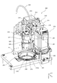
- FIG. 1 is a diagram schematically illustrating a configuration when the nucleic acid analyzer according to the first embodiment is viewed from above.
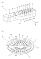
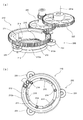
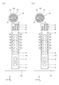
- FIG. 2A is a perspective view schematically illustrating the configuration of the first container according to the first embodiment.
- FIG. 2B is a perspective view schematically showing the configuration of the second container according to the first embodiment.
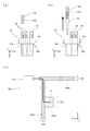
- FIGS. 3A and 3B are side views schematically showing the configuration of the third container and the suction part according to the first embodiment.
- FIG.3 (c) is a figure which shows typically the structure of the dispensing unit which concerns on Embodiment 1.
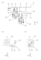
- FIG. FIG. 4A is a cross-sectional view schematically showing the configuration of the temperature adjustment unit arranged under the first container installation unit according to the first embodiment.
- FIG. 4B and 4C are diagrams schematically illustrating the configuration of the magnetic force application unit according to the first embodiment.
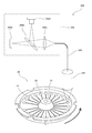
- FIG. 5 is a diagram schematically illustrating the configuration of the detection unit according to the first embodiment.
- FIG. 6 is a perspective view illustrating configurations of a rotation unit, a detection unit, and an urging unit according to the first embodiment.
- FIG. 7A is a perspective view illustrating configurations of a container installation unit, a rotation drive unit, and a guide unit according to the first embodiment.
- FIG. 7B is a plan view illustrating the configuration of the container installation unit and the guide unit according to the first embodiment.
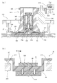
- FIG. 8 is a cross-sectional view schematically illustrating the configuration of the urging unit, the second container, the container installation unit, and the first temperature adjustment unit according to the first embodiment.
- FIGS. 9A and 9B show the positional relationship between the urging unit, the second container, the container installation unit, and the first temperature adjustment unit when the pressing member according to the first embodiment is positioned at the first position. It is sectional drawing shown typically.
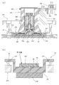
- FIGS. 10A and 10B show the positional relationship between the urging unit, the second container, the container installation unit, and the first temperature adjustment unit when the pressing member according to the first embodiment is positioned at the second position. It is sectional drawing shown typically.
- 11A and 11B show the positional relationship between the urging unit, the second container, the container installing unit, and the first temperature adjusting unit when the pressing member according to the first embodiment is positioned at the third position. It is sectional drawing shown typically.
- FIG. 10A and 10B show the positional relationship between the urging unit, the second container, the container installation unit, and the first temperature adjustment unit when the pressing member according to the first embodiment is positioned at the second position. It is sectional drawing shown typically.
- FIG. 10A and 10B show the positional relationship between
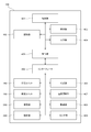
- FIG. 12 is a block diagram illustrating a configuration of the nucleic acid analyzer according to the first embodiment.
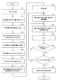
- FIG. 13 is a flowchart showing processing of the nucleic acid analyzer according to the first embodiment.
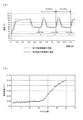
- FIG. 14A is a diagram illustrating an example of a graph showing a relationship between elapsed time and temperature according to the first embodiment.
- FIG. 14B is a diagram illustrating an example of a graph showing the relationship between the number of cycles and the fluorescence intensity according to the first embodiment.
- FIG. 15A is a diagram for explaining the acquisition of the cycle number based on the threshold value of the fluorescence intensity in the graph showing the relationship between the cycle number and the fluorescence intensity according to the first embodiment.
- FIG. 14A is a diagram illustrating an example of a graph showing a relationship between elapsed time and temperature according to the first embodiment.
- FIG. 14B is a diagram illustrating an example of a graph showing the relationship between the number of cycles and the fluorescence intensity according to the first embodiment.
- FIG. 15B is a diagram for explaining that the amount of mutation is acquired based on the acquired number of cycles according to the first embodiment.
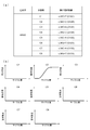
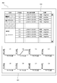
- FIG. 16A is a diagram illustrating an example of genes to be analyzed by the nucleic acid analyzer according to the first embodiment, names of the respective storage units, and detection target nucleic acids detected in the respective storage units.
- FIG. 16B is a diagram illustrating an example of a graph showing the relationship between the number of cycles and the fluorescence intensity based on each storage unit according to the first embodiment.
- FIG. 17 is a diagram schematically illustrating a result screen displayed on the display unit according to the first embodiment.
- FIGS. 18A and 18B are diagrams schematically illustrating the arrangement of the second container installation unit according to the second embodiment.
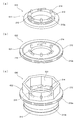
- FIGS. 19A to 19C are perspective views schematically showing the configuration of the container installation section according to the third embodiment.
- FIGS. 20A to 20D are diagrams schematically showing the configuration of the floating prevention mechanism according to the fourth embodiment.
- FIG. 21A is a cross-sectional view schematically showing the configuration of the urging unit according to the fifth embodiment.
- FIG. 21B schematically shows a positional relationship among the urging unit, the second container, the container installation unit, and the first temperature control unit when the pressing member according to the fifth embodiment is positioned at the second position. It is sectional drawing.
- FIG. 22 is a diagram schematically illustrating a configuration when the nucleic acid analyzer according to the sixth embodiment is viewed from above.
- the present invention is applied to an apparatus that automatically performs from nucleic acid extraction to real-time PCR, detection of nucleic acid amplification reaction, and nucleic acid analysis.
- the nucleic acid analyzer 100 includes a plate member 101, a dispensing unit 140, temperature control units 150 and 160, a magnetic force application unit 170, a transfer unit 180, a rotation unit 200, and a first unit.
- a temperature adjustment unit 230 and a detection unit 240 are provided.
- the XYZ axes are orthogonal to each other. The X-axis positive direction indicates the rear, the Y-axis positive direction indicates the left direction, and the Z-axis positive direction indicates the vertically downward direction. In the following drawings, the XYZ axes are the same as the XYZ axes shown in FIG.
- the X axis corresponds to the first axis
- the Y axis corresponds to the second axis.
- the X axis and the Y axis intersect perpendicularly, but do not have to intersect completely perpendicularly.
- the plate member 101 is parallel to the XY plane.
- the plate member 101 is provided with three first container placement portions 110, three second container placement portions 120, and three third container placement portions 130.
- the plate member 101 includes three rows of one first container placement portion 110, one second container placement portion 120, and one third container placement portion 130 arranged along the X axis in plan view. Is provided. In other words, in plan view, the three first container installation parts 110 are arranged along the Y axis, the three second container installation parts 120 are arranged along the Y axis, and the three third container installation parts 130 are Arranged along the Y-axis.
- the first container installation unit 110 is an installation unit for installing the first container 10.
- the first container installation unit 110 includes an opening 111 formed in the plate member 101 and a support plate 112 that is vertically below the plate member 101. In plan view, the opening 111 has a slightly larger outline than the outer shape of the first container 10, and the support plate 112 is provided on the rear side of the opening 111.
- the first container 10 is configured such that the lower end 10b of the first container 10 shown in FIG. 2A is supported vertically by the support plate 112, and the side surface of the first container 10 is supported by the opening 111. It is installed in one container installation unit 110.
- the first container 10 is installed in the first container installation unit 110.
- the first container 10 installed in the first container installation unit 110 has a shape that is long in the X-axis direction.
- the first container 10 includes a reaction unit 11, a reagent storage unit 12, reagent storage units 13a to 13h, mixing units 14a to 14d, a reagent storage unit 15, And a waste liquid storage unit 16.
- the reaction unit 11, the reagent storage unit 12, the reagent storage units 13a to 13h, the mixing units 14a to 14d, the reagent storage unit 15 and the waste liquid storage unit 16 are provided in the first container 10 so that the upper part is opened. It is a well that can contain liquid.
- the reagent storage units 12, 13a to 13h store in advance a reagent for nucleic acid extraction.
- the reagent container 12, the reagent containers 13a to 13h, and the upper part of the waste liquid container 16 are sealed with an aluminum seal 10a.
- the reagent container 15 stores the reagent when the first container 10 is installed in the first container installation unit 110.
- the reagent storage unit 12 stores a reagent containing magnetic particles and a magnetic particle storage solution in advance
- the reagent storage units 13a to 13h include a solubilization solution, proteinase K, oil, The eluate, the extraction reagent stock solution, the second washing solution stock solution, the diluted solution stock solution, and the first washing solution stock solution are accommodated.
- the extraction of nucleic acid using the first container 10 will be described later with reference to FIG.
- 1st container 10 is installed in the 1st container installation part 110 so that a plurality of reagent storage parts of the 1st container 10 may be arranged along the X-axis.
- the reaction unit 11 and the reagent storage unit 12 are also arranged along the X axis.
- the second container installation unit 120 is an installation unit for installing the second container 20.
- the three second container installation parts 120 are respectively arranged on the X axis positive direction side of the three first container installation parts 110. Thereby, the second container installation unit 120 is arranged on the X axis positive direction side of the first container 10 installed in the first container installation unit 110.
- the second container installation unit 120 includes an upper surface of the plate member 101 and three pins 121 installed on the upper surface of the plate member 101.
- the second container 20 is installed in the second container installation unit 120 when an engaged portion 27 a of the second container 20 described later engages with the three pins 121.
- the 2nd container installation part 120 is arrange
- the second container 20 includes an injection port 21, 23 storage units 22, and 23 flow paths 23 that connect the injection port 21 and the 23 storage units 22.
- the second container 20 is a disk-shaped container in which an injection port 21 is disposed at a central position, and 23 accommodating portions 22 are disposed at regular intervals in the circumferential direction from the central position to a position on the outer peripheral side having a constant diameter.
- the center position of the second container 20 is the rotation center when the second container 20 is rotated, as will be described later.
- the twenty-three storage portions 22 are arranged side by side in the circumferential direction at a certain diameter from the rotation center of the second container 20.
- the second container 20 is a disk-shaped container, but the second container 20 is not necessarily a disk-shaped container.
- the second container 20 includes an upper surface portion 24, a protrusion 25, a lower surface portion 26, and a flange portion 27.
- the protrusion 25 is disposed at the center position of the second container 20.
- the protrusion 25 is reduced in thickness in the vertical direction toward the end of the second container 20, and is axisymmetric with respect to a straight line passing through the center position of the second container 20 and parallel to the vertical direction.
- the protrusion 25 includes an upper surface portion 25a and a slope portion 25b.
- the upper surface of the upper surface portion 25a is parallel to the horizontal plane.
- the injection port 21 is a hole formed in the upper surface portion 25a and parallel to the vertical direction.
- the upper surface portion 24 is made of a translucent member.
- the upper surface of the upper surface portion 24 is a surface parallel to the horizontal plane, and a recess and a groove for forming the accommodating portion 22 and the flow path 23 are formed on the lower surface of the upper surface portion 24, respectively.
- the lower surface portion 26 is made of thin film aluminum having high thermal conductivity. The lower surface portion 26 is attached to the ABS resin attached to the lower surface of the upper surface portion 24 from below.
- the collar portion 27 is a flat plate parallel to a horizontal plane formed outside the upper surface portion 24.
- the hook portion 27 is formed with three engaged portions 27a.
- the engaged portion 27a is a notch.
- the engaged portion 27a is engaged with an engaging portion 214 of a container installing portion 210 described later.
- the engaged portion 27a may be engaged with the engaging portion 214 of the container setting portion 210, and may be a hole, a concave portion, a protrusion, or the like instead of the notch.
- the extraction liquid containing the nucleic acid extracted in the first container 10 located on the X axis negative side is injected into the injection port 21.
- the storage unit 22 stores in advance a reagent for amplifying the nucleic acid in the extract.
- the second container 20 is a reaction container for reacting the extract injected from the injection port 21 with the reagent in the storage unit 22.
- the second container 20 for performing nucleic acid amplification is provided with a plurality of accommodating portions 22, and the nucleic acid extracted in the first container 10 arranged on the X-axis negative direction side, Nucleic acids can be analyzed at the same time as the number of accommodating portions 22. Thereby, the efficiency of analysis can be improved.
- a plurality of analyzes can be performed in parallel only by installing one second container 20 for the extracted nucleic acid. Therefore, the installation area of the nucleic acid analyzer 100 can be suppressed.
- the inlet 21 of the second container 20 installed in the second container installation unit 120 is positioned at the approximate center of the width of the first container 10 in the Y-axis direction in the Y-axis direction in plan view. Thereby, the 1st container 10 and the 2nd container 20 will be arrange
- the third container installation unit 130 is an installation unit for installing the third container 30.
- the third container installation unit 130 includes an opening 131 formed in the plate member 101 and a support plate 132 that is vertically below the plate member 101. In a plan view, the opening 131 has a contour that is slightly larger than the outer shape of the third container 30.
- An opening 132 a is formed in the support plate 132.
- the body of the third container 30 is passed through the opening 132 a, and the lower surface 30 a of the flange formed on the outer periphery of the third container 30 shown in FIG. By being supported in the direction, it is installed in the third container installation unit 130.
- the third container 30 is installed in the third container installation unit 130.
- the third container 30 holds one puncture tip 31 and seven pipette tips 32.
- the puncture tip 31 is a tip for piercing the aluminum seal 10a of the first container 10 so as to open the upper part of the housing part below the aluminum seal 10a.
- the pipette tip 32 has a hole penetrating in the vertical direction.
- FIGS. 3A and 3B when the suction part 141 of the dispensing unit 140 is lowered from directly above the pipette tip 32, the pipette tip 32 is attached to the lower end of the suction part 141. Then, the pipette tip 32 is extracted from the third container 30 by raising the suction part 141. Similarly, the puncture tip 31 is attached to the lower end of the suction portion 141.
- a hole 141 a is formed in the suction part 141 so that liquid can be sucked and discharged from the lower end of the suction part 141.
- the dispensing unit 140 transfers the extract contained in the first container 10 from the first container 10 to the inlet 21 of the second container 20.
- the dispensing unit 140 includes a suction unit 141, a pump 142, a vertical transfer unit 143, a front / rear transfer unit 144, and a left / right transfer unit 145.
- the suction part 141 is detachable from the puncture tip 31 and the pipette tip 32.
- the suction part 141 is configured by a nozzle.
- the pump 142 is connected to the hole 141 a of the suction part 141.
- the pump 142 applies a positive pressure and a negative pressure to the suction unit 141 and sucks and discharges the liquid through the pipette tip 32 attached to the lower end of the suction unit 141.
- the vertical transfer unit 143 includes a rail 143a extending along the Z axis and a stepping motor (not shown).
- the vertical transfer unit 143 drives the stepping motor to transfer the suction unit 141 in the Z-axis direction along the rail 143a.
- the front-rear transport unit 144 includes a rail 144a extending along the X axis and a stepping motor (not shown).
- the rail 144a is a rail for moving the suction portion 141 along the X axis.
- the front / rear transport unit 144 drives the stepping motor to transport the vertical transport unit 143 in the X-axis direction along the rail 144a.
- the left-right transfer unit 145 includes a rail 145a extending along the Y axis and a stepping motor (not shown).
- the rail 145a is a rail for moving the suction part 141 along the Y axis.
- the left / right transfer unit 145 drives the stepping motor to transfer the front / rear transfer unit 144 in the Y-axis direction along the rail 145a.
- the suction unit 141, the vertical transfer unit 143, the front / rear transfer unit 144, and the left / right transfer unit 145 can move along the XYZ axes inside the nucleic acid analyzer 100.
- the dispensing unit 140 transfers the extract from the first container 10 to the second container 20 along the X axis. Specifically, the dispensing unit 140 aspirates the extract from the first container 10 by the pipette tip 32 attached to the aspirating unit 141. Thereafter, the dispensing unit 140 moves the pipette tip 32 to the inlet 21 of the second container 20 arranged on the X axis positive direction side of the first container 10 that sucked the extract. Then, the dispensing unit 140 discharges the extract from the inlet 21 to the second container 20.
- the first container 10 is provided with two rows of a plurality of reagent storage portions arranged along the X axis in the Y axis direction in plan view. Specifically, the first container 10 is provided with rows of reagent storage portions 13a, 13c, 13e, and 13g and rows of reagent storage portions 13b, 13d, 13f, and 13h.
- the dispensing unit 140 moves the pipette tip 32 in the X-axis direction and the Y-axis direction, and aspirates the reagent from the reagent storage units 13a to 13h.
- the length in the X-axis direction of the 1st container 10 can be compressed compared with the case where all the reagent storage parts are located in a line with the X-axis direction. Therefore, the layout in the nucleic acid analyzer 100 can be made compact.
- the dispensing unit 140 dispenses the reagent in each first container 10 installed in each first container installation unit 110 through a dispensing path set for each of the three first container installation units 110. Do. That is, one dispensing unit 140 performs a dispensing operation on the three first container installation units 110. Similarly, one dispensing unit 140 performs a dispensing operation on the three second container installation units 120. Thus, when one common dispensing unit 140 is used for each container, the layout in the nucleic acid analyzer 100 can be made compact compared to the case where a plurality of dispensing units are used.
- the temperature adjustment units 150 and 160 are arranged at a front position in the opening 111 of the first container installation unit 110 in a plan view.
- the temperature adjustment unit 150 includes a heat block 151 and a heater 152, and heats the reaction unit 11 of the first container 10 installed in the first container installation unit 110.
- a hole 151 a having substantially the same shape as that of the reaction portion 11 is formed.
- the temperature adjustment unit 160 includes a heat block 161 and a heater 162, and heats the reagent storage unit 12 of the first container 10 installed in the first container installation unit 110.
- the temperature adjustment unit 160 is moved upward, and the reagent storage unit 12 is stored in the hole 161a. In this state, the heat of the heater 162 is transmitted to the reagent storage unit 12 through the heat block 161.
- the temperature adjustment unit 160 is moved downward.
- the magnetic force application unit 170 is disposed vertically below the plate member 101 and is configured to be movable in the Y-axis direction.
- the magnetic force application unit 170 includes a support portion 171 and two magnets 172.
- the temperature adjustment unit 160 is retracted vertically downward.
- the magnetic force application unit 170 is brought close to the reagent storage unit 12 of the first container 10 installed in the first container installation unit 110.
- the magnetic particles contained in the reagent storage unit 12 are attracted to the magnet 172 as shown in FIG. 4C, and the X axis of the reagent storage unit 12 is drawn. Adsorbs to the negative wall surface and the Y-axis negative wall surface.
- the transfer unit 180 includes a hand unit 181 and a mechanism for moving the hand unit 181 along the Y-axis direction.
- the transfer unit 180 grips and transfers the second container 20 between the second container installation part 120 and the position of the rotating part 200.
- the transfer unit 180 is injected with the extract and transfers the second container 20 installed in the second container installation unit 120 to the position of the rotating unit 200.
- the transfer unit 180 may suck and transfer the upper surface of the upper surface part 24 of the second container 20 by the suction unit.
- the rotation unit 200 includes a container installation unit 210 and a rotation drive unit 220.
- the second container 20 is installed in the container installation unit 210.
- the rotating unit 200 rotates the second container 20 into which the extract has been injected in order to send the extract to the storage unit 22 through the flow path 23 by centrifugal force.
- the rotation drive unit 220 rotates the container installation unit 210 on which the second container 20 is installed by applying a driving force to a first outer surface 212 of the container installation unit 210 to be described later.
- the second container 20 is rotated by rotating 210, and the extraction liquid injected from the injection port 21 is sent to the storage unit 22 through the flow path 23 by centrifugal force.
- the first temperature adjusting unit 230 is rotated by the rotating unit 200 to adjust the temperature of the second container 20 installed in the container installing unit 210 so that the nucleic acid amplification reaction occurs in the housing unit 22.
- the first temperature adjustment unit 230 is configured by a Peltier element.
- the storage unit 22 stores in advance a reagent for amplifying a detection target nucleic acid in which a mutation has occurred in the detection target site of the nucleic acid and a reagent including a fluorescent probe that binds to the detection target nucleic acid.
- the fluorescent probe contains a fluorescent substance.
- the detection target nucleic acid is labeled with a fluorescent substance.
- fluorescence is generated from the fluorescent material when the fluorescent material of the fluorescent probe is irradiated with excitation light.
- the fluorescent probe is not bound to the detection target nucleic acid, no fluorescence is generated from the fluorescent substance even when the fluorescent substance of the fluorescent probe is irradiated with excitation light.
- the nucleic acid amplification reaction occurs in the storage unit 22 by adjusting the temperature by the first temperature control unit 230.
- the detection target nucleic acid is contained in the nucleic acid
- the detection target nucleic acid is amplified in the accommodation unit 22
- the detection target nucleic acid is not amplified in the accommodation unit 22. Therefore, when the detection target nucleic acid is amplified, the amplified detection target nucleic acid is labeled with the fluorescent substance of the fluorescent probe, so that fluorescence is generated according to the amplification amount when the accommodating portion 22 is irradiated with excitation light. It will be.
- the rotating unit 200 moves the storage units 22 so that the temperature-controlled storage units 22 are sequentially positioned at detection positions by the detection unit 240.
- the rotation driving unit 220 rotates the container installation unit 210 to sequentially position the storage units 22 of the second containers 20 installed in the container installation unit 210 at the detection positions according to a predetermined order.
- the detection unit 240 detects a nucleic acid amplification reaction occurring in the storage unit 22 positioned at the detection position by the rotation unit 200. Specifically, the detection unit 240 detects the intensity of the fluorescence signal indicating the amount of amplification product obtained by the nucleic acid amplification reaction.
- the detection unit 240 includes a detection head 241 and an optical unit 242 connected to the detection head 241 via an optical fiber 243.
- the detection unit 240 detects the nucleic acid amplification reaction by irradiating the storage unit 22 of the second container 20 with light.
- the detection head 241 is disposed so as to irradiate the housing portion 22 with light and to face the housing portion 22 of the second container 20.
- the optical unit 242 includes a light source 242a, a dichroic mirror 242b, a condenser lens 242c, and a photodetector 242d.
- the light source 242a emits excitation light having a predetermined wavelength.
- the excitation light emitted from the light source 242a excites the fluorescent substance of the fluorescent probe to generate fluorescence when the fluorescent probe is bound to the detection target substance.
- the dichroic mirror 242b reflects the excitation light emitted from the light source 242a and transmits the fluorescence generated from the fluorescent material of the fluorescent probe.
- the condensing lens 242c condenses the excitation light reflected by the dichroic mirror 242b and guides it to the optical fiber 243.
- the condensing lens 242c condenses the fluorescence emitted from the optical fiber 243 to the condensing lens 242c and guides it to the dichroic mirror 242b.
- the photodetector 242d receives the fluorescence transmitted through the dichroic mirror 242b, measures the intensity of the received fluorescence, and outputs an electrical signal corresponding to the intensity of the fluorescence.
- the analysis unit 401 described later generates a plurality of time-series data indicating the nucleic acid amplification reaction occurring in each storage unit 22 from the fluorescent electrical signal detected by the photodetector 242d of the detection unit 240. Then, the analysis unit 401 determines whether or not the detection target substance is included in each storage unit 22 based on the time series data, and displays a determination result or the like on the display unit 403 described later. Thus, the nucleic acid analysis is completed.
- the rotating unit 200, the first temperature adjusting unit 230, and the detecting unit 240 are arranged at the same position in plan view. That is, when viewed from above, a part of the rotating unit 200, a part of the first temperature adjusting unit 230, and a part of the detecting unit 240 overlap each other.
- temperature adjustment and detection for the second container 20 can be performed smoothly. Therefore, real-time PCR can be performed on each storage unit 22 of the second container 20.
- the rotation unit 200, the first temperature adjustment unit 230, and the detection unit 240 can be compactly arranged in the nucleic acid analyzer 100.
- the rotation unit 200, the first temperature adjustment unit 230, and the detection unit 240 are at different positions from the straight line connecting the first container installation unit 110 and the second container installation unit 120.
- the transfer unit 180 transfers the second container 20 installed in the second container installation unit 120 to the positions of the rotation unit 200, the first temperature adjustment unit 230, and the detection unit 240.
- the rotation drive unit 220 rotates the container installation unit 210 by applying a driving force to the first outer surface 212 of the container installation unit 210 where the second container 20 is installed, and the detection unit 240 causes the container installation unit 210 to rotate.
- the first temperature adjustment unit 230 is disposed on the lower side of the second container 20 installed in the container installation unit 210.
- the first temperature adjustment unit 230 and the detection unit 240 may be arranged at positions where the second container 20 installed in the container installation unit 210 is sandwiched vertically, and the detection unit 240 is connected to the container installation unit 210. What is necessary is just to detect the nucleic acid amplification reaction which arises in the accommodating part 22 so that the installed 2nd container 20 may be pinched
- the detection unit 240 is disposed below the second container 20 installed in the container installation unit 210, and the first temperature adjustment unit 230 is disposed above the second container 20 installed in the container installation unit 210. May be.
- the container installation unit 210 includes an inner surface 211, a first outer surface 212, a second outer surface 213, three engagement portions 214, Three elastic members 215.
- the shape of the container installation part 210 is a cylindrical shape whose upper and lower sides are open.
- the container installation part 210 does not necessarily need to be cylindrical.
- the container installation part 210 should just be the cylindrical shape of the 1st outer surface 212 and the groove
- the shape of the container installation part 210 does not necessarily need to be opened up and down.
- the container installation part 210 may include a bottom part having high thermal conductivity. In this case, the temperature of the lower surface of the lower surface portion 26 of the second container 20 may be adjusted by the first temperature adjustment unit 230 via the bottom surface of the container installation unit 210.
- the inner side surface 211, the first outer side surface 212, and the second outer side surface 213 are cylindrical.
- a gear portion 212 a is formed on the first outer surface 212.
- On the second outer surface 213, a groove 213 a having a constant width is formed in the vertical direction over the entire circumference of the second outer surface 213.
- the nucleic acid analyzer 100 includes a guide unit 250 that contacts the second outer surface 213 and guides the rotation of the container installation unit 210.
- the guide portion 250 includes three guide members 251 that fit into the grooves 213a of the second outer surface 213.
- the guide member 251 is configured by a roller. When the guide member 251 is fitted into the groove 213a, the container installation unit 210 can rotate with the position in the horizontal plane and the position in the vertical direction fixed.
- variety may be formed in the perpendicular direction over the perimeter of the 2nd outer side surface 213.
- a plurality of two rollers that sandwich the upper and lower portions of the protrusion of the second outer surface 213 may be disposed on the outer periphery of the second outer surface 213.
- a shelf parallel to the horizontal plane is provided over the entire circumference of the inner side surface 211 below the inner side surface 211 of the container setting unit 210.
- the engaging portion 214 and the elastic member 215 are arranged on a shelf below the inner side surface 211.
- the engaging portion 214 has a cylindrical shape having a diameter slightly smaller than the diameter of the engaged portion 27a of the second container 20.
- the elastic member 215 is configured by a leaf spring.
- the second container 20 is inserted into the inner side surface 211 and installed in the container installation unit 210. Specifically, the engaging portion 214 engages with the engaged portion 27a of the second container 20, and the elastic member 215 supports the lower surface of the flange portion 27 of the second container 20, whereby the second container 20 is installed in the container installation unit 210.
- the rotation drive unit 220 includes a motor 221 and transmission gears 222 and 223. Further, the rotation drive unit 220 includes a gear unit 212 a formed on the first outer side surface 212 of the container installation unit 210 as a component.
- the motor 221 is a stepping motor.
- the transmission gears 222 and 223 connect the drive shaft 221 a of the motor 221 and the gear portion 212 a of the first outer surface 212.
- the center of the transmission gear 222 is connected to the drive shaft 221 a of the motor 221.
- the transmission gear 222 meshes with a gear part above the transmission gear 223.
- the gear portion 212 a of the first outer surface 212 meshes with the gear portion below the transmission gear 223.
- the diameter of the gear part above the transmission gear 223 is smaller than the diameter of the gear part below the transmission gear 223.
- the transmission gear 223 functions as an acceleration gear. Therefore, the rotation speed of the container installation portion 210 can be increased more than the rotation speed of the drive shaft 221a. it can.
- a belt spanned between the outer periphery of the drive shaft 221a and the outer periphery of the first outer surface 212 may be used as a means for transmitting the driving force of the motor 221 to the container installation unit 210.
- a belt spanned between the outer periphery of the drive shaft 221a and the outer periphery of the first outer surface 212 may be used.
- the belt slips, and thus it is necessary to keep the drive shaft 221a and the first outer surface 212 away from each other.
- the installation area of the nucleic acid analyzer 100 increases. Therefore, as described above, it is desirable that the driving force of the motor 221 is transmitted to the container installation unit 210 by the transmission gears 222 and 223 and the gear unit 212a.
- the nucleic acid analyzer 100 includes an urging unit 300 at the position of the rotating unit 200, the first temperature adjusting unit 230, and the detecting unit 240.
- the urging unit 300 is disposed on the opposite side of the first temperature adjustment unit 230 with respect to the second container 20 installed in the container installation unit 210. Specifically, it is disposed above the second container 20 installed in the container installation unit 210.
- the urging unit 300 urges the second container 20 installed in the container installation unit 210 toward the first temperature adjustment unit 230.
- the urging unit 300 includes a moving mechanism 310, a support body 320, and a pressing member 330.
- the moving mechanism 310 includes a motor 311, a belt 312, a gear 313, a support portion 314, a spring 315, a support member 316, and a rail 317.
- the motor 311 is a stepping motor.
- the belt 312 connects the drive shaft of the motor 311 and the gear 313.
- the gear 313 is installed on a member in the nucleic acid analyzer 100 so as to be rotatable.
- the support portion 314 is installed on the gear 313 so as to move up and down in accordance with the rotation of the gear 313.
- the upper end of the spring 315 is installed on the lower surface of the support portion 314, and the lower end of the spring 315 is installed on the upper surface of the support member 316.
- the support member 316 is installed on the rail 317 so as to be movable along the rail 317.
- the rail 317 is installed on a member in the nucleic acid analyzer 100 and extends in the vertical direction.
- the support 320 is installed on the lower surface of the support member 316.
- the pressing member 330 is installed at the lower end of the support 320.
- the drive shaft of the motor 311 rotates
- the gear 313 rotates and the support portion 314 moves up and down.
- the support part 314 moves up and down
- the support member 316, the support body 320, and the pressing member 330 move up and down via the spring 315 in accordance with the movement of the support part 314.
- the pressing member 330 can press the surface of the second container 20 installed in the container installation unit 210 on the side opposite to the first temperature adjusting unit 230.
- the pressing member 330 can press the upper surface of the upper surface portion 24 of the second container 20 installed in the container installation unit 210.
- the detection head 241 is disposed on the opposite side of the first temperature adjustment unit 230 with respect to the second container 20 installed in the container installation unit 210.
- the detection head 241 is supported by a support member 316 that supports the pressing member 330 and moves up and down. Note that the entire detection unit 240 may be supported by the support member 316.
- FIG. 8 shows a part of the moving mechanism 310, the support 320, the pressing member 330, the container installation unit 210, and the second container 20 positioned immediately above the container installation unit 210. It is a figure which shows the cut surface cut
- the support 320 has a hole 320a penetrating in the vertical direction.
- the support body 320 includes a bearing portion 321, a support member 322, a shaft member 323, a receiving member 324, and a heat insulating member 325 in the hole 320 a.
- the bearing portion 321 is fixed to the hole 320a.
- the support member 322 is supported by the bearing portion 321 so as to be rotatable about the vertical direction as the center of rotation.
- the shaft member 323 is installed at the lower end of the support member 322 so as to coincide with the rotation axis of the support member 322.
- the shaft member 323 is configured such that the shaft diameter at the lower end portion is slightly smaller than the inlet 21. Thereby, the shaft member 323 comes to fit into the injection port 21 of the second container 20, and the backflow of the liquid from the injection port 21 is suppressed.
- the shaft member 323 is a shaft defining portion that engages with the inlet 21 of the second container 20 installed in the container installing portion 210 and defines the rotation axis of the second container 20.
- the receiving member 324 is installed on the lower surface of the support member 322 so as to surround the periphery of the shaft member 323.
- the receiving member 324 is made of fluororubber.
- the receiving member 324 has a circular shape with a hole penetrating vertically in the central portion in plan view, and the outer peripheral portion of the lower surface swells downward.
- the urging unit 300 includes a second temperature adjusting unit 340.
- the second temperature adjustment unit 340 is installed on the lower surface of the support 320 via a heat insulating member 325.
- the second temperature adjustment unit 340 adjusts the temperature of the second container 20 installed in the container installation unit 210.
- the second temperature adjustment unit 340 is a heater, and heats the second container 20 by heating the upper surface of the upper surface part 24 of the second container 20.
- the pressing member 330 is installed on the lower surface of the second temperature adjusting unit 340 and the lower surface of the support 320, and the outer diameter of the pressing member 330 is larger than the outer diameter of the support 320.
- the pressing member 330 has a hole 331 that presses a region overlapping the 23 accommodating portions 22 of the second container 20 and penetrates vertically at a position corresponding to the accommodating portion 22.
- the detection unit 240 detects the storage unit 22 through the hole 331.
- a hole 332 is formed in the center of the pressing member 330 so as to penetrate the pressing member 330 in the vertical direction.
- the first temperature adjustment unit 230 is located on the lower surface of the lower surface portion 26 of the second container 20 installed in the container installation unit 210 from the center position of the second container 20 to at least the radial position where the storage unit 22 is disposed. And a temperature control surface covering the entire area. That is, the diameter of the first temperature adjustment unit 230 is set to be at least equal to or larger than the diameter of the circle in which the storage units 22 are arranged. Thereby, temperature control of the accommodating part 22 can be performed smoothly.
- the elastic member 215 moves the second container 20 away from the first temperature adjustment unit 230.
- the urging unit 300 resists the urging by the elastic member 215 and causes the second container 20 installed in the container installation unit 210 to have the first temperature. It moves in the direction toward the adjustment unit 230.
- the pressing member 330 presses the second container 20 downward, and the lower surface of the lower surface portion 26 of the second container 20 is the first temperature adjusting portion 230. It is made into the state which touches the upper surface of this.
- the support portion 314 is further moved downward, so that the spring 315 is contracted as shown in FIG.
- the second container 20 is pressed against the first temperature adjustment unit 230 via the support member 316, the support body 320, and the pressing member 330.
- the position of the pressing member 330 when the pressing member 330 abuts against the second container 20 and presses the second container 20 is hereinafter referred to as a “first position”.
- the first temperature adjustment unit 230 and the second temperature adjustment unit 340 perform temperature adjustment on the second container 20.
- the first position, the second position and the third position described later are stored in a storage unit 402 described later, and are read from the storage unit 402 when the control unit 405 drives the biasing unit 300.
- the pressing member 330 is It positions so that it may contact the upper surface part 24 of the 2nd container 20 slightly. At this time, the pressing member 330 slightly presses the upper surface of the upper surface portion 24 of the second container 20 supported by the elastic member 215, and the elastic member 215 is slightly contracted. Thereby, even if the container installation part 210 rotates at high speed from the state of Fig.9 (a), (b) and the 2nd container 20 is rotated at high speed, the motion of the 2nd container 20 in the vertical direction is suppressed.
- the position of the pressing member 330 when the second container 20 is rotated at a high speed is referred to as a “second position”.
- the second position is a position that is farther from the first temperature adjustment unit 230 than the first position, and is a position that restricts the movement of the second container 20 in the vertical direction.
- the rotation driving unit 220 rotates the second container 20 at a high speed by rotating the container setting unit 210 at a high speed.
- the shaft member 323 When the pressing member 330 is positioned at the second position, the shaft member 323 is inserted into the injection port 21, and the receiving member 324 comes into contact with the upper surface portion 25a of the protrusion 25.
- the second container 20 is rotated at a high speed in this state, the shaft member 323 and the receiving member 324 are rotated, and the support member 322 provided with the shaft member 323 and the receiving member 324 is rotated.
- the rotating shaft of the 2nd container 20 is prescribed
- the lower surface portion 26 of the second container 20 has the first temperature control. Without being pressed against the upper surface of the portion 230, it is in a state of slightly touching.
- the position of the pressing member 330 at this time is hereinafter referred to as a “third position”.
- the third position is a position between the first position and the second position, and more specifically is a position moved slightly upward from the first position.
- the detection unit 240 detects the nucleic acid amplification reaction for the storage unit 22 of the second container 20.
- the second container 20 When the pressing member 330 is positioned at the third position, the second container 20 is pushed upward by the elastic member 215 and pushed downward by the pressing member 330. Thereby, since the position of the second container 20 in the vertical direction becomes a predetermined position, the focal position of the excitation light irradiated from the detection head 241 through the hole 331 to the irradiation position is set to a desired vertical direction in the housing unit 22. Can be positioned at
- the nucleic acid analyzer 100 includes the dispensing unit 140, the transfer unit 180, the rotating unit 200, the detecting unit 240, and the biasing unit 300, as described above.
- the nucleic acid analyzer 100 also includes an analysis unit 401, a storage unit 402, a display unit 403, an input unit 404, a control unit 405, an interface 406, a temperature adjustment unit 407, a drive unit 408, and a sensor unit. 409.
- the analysis unit 401 is constituted by a CPU. When the analysis unit 401 receives a start instruction via the input unit 404, the analysis unit 401 transmits an instruction signal to the control unit 405 so as to start the nucleic acid analysis process.
- the analysis unit 401 generates a plurality of time-series data indicating the nucleic acid amplification reaction occurring in each storage unit 22 of the second container 20 from the fluorescent electrical signal detected by the detection unit 240. Based on the generated time-series data, the analysis unit 401 determines whether the detection target nucleic acid whose nucleic acid detection target site is mutated is positive or negative.
- the storage unit 402 includes a RAM, a ROM, a hard disk, and the like.
- the display unit 403 is configured by a display.
- the input unit 404 is configured with a keyboard, a mouse, and the like.
- the nucleic acid analyzer 100 may include a display input unit configured by a touch panel display instead of the display unit 403 and the input unit 404.
- the control unit 405 is configured by a CPU or a microcomputer.
- the control unit 405 includes a dispensing unit 140, a transfer unit 180, a rotating unit 200, a detecting unit 240, a biasing unit 300, a temperature adjusting unit 407, a driving unit 408, and a sensor via an interface 406.
- Part 409 The temperature adjustment unit 407 includes temperature adjustment units 150 and 160, a first temperature adjustment unit 230, and a second temperature adjustment unit 340.
- the drive unit 408 includes various drive units arranged in the nucleic acid analyzer 100.
- the sensor unit 409 includes various sensors arranged in the nucleic acid analyzer 100.
- the operator When analyzing the sample by the nucleic acid analyzer 100, the operator installs a new first container 10 in the first container installation unit 110 and stores the sample in the reaction unit 11 of the first container 10.
- the specimen of Embodiment 1 is a formalin-fixed paraffin-embedded (FFPE) tissue section.
- the operator stores ethanol in the reagent storage unit 15.
- the operator installs a new second container 20 in the second container installation unit 120.
- the new second container 20 accommodates reagents for amplifying and fluorescently labeling different detection target nucleic acids in each accommodating portion 22.
- the operator installs a new third container 30 in the third container installation unit 130.
- the nucleic acid analyzer 100 can perform nucleic acid analysis on three samples in parallel.
- the nucleic acid analyzer 100 includes three sets including the first container installation unit 110, the second container installation unit 120, and the third container installation unit 130 that are arranged along the X-axis direction. One set is used for each specimen.
- the operator installs the first container 10, the second container 20, and the third container 30 for the plurality of sets.
- a procedure for nucleic acid analysis in one set will be described.
- the control unit 405 drives the dispensing unit 140 to attach the puncture tip 31 to the lower end of the suction unit 141.
- the control unit 405 drives the dispensing unit 140 to pierce the puncture tip 31 into the aluminum seal 10a, whereby the reagent storage unit 12, the reagent storage units 13a to 13h, and the waste liquid storage unit of the first container 10 Open the top of 16.
- the control unit 405 drives the dispensing unit 140 to purify the extract in the first container 10.
- the pipette tip 32 is appropriately attached to and exchanged with respect to the suction portion 141, and the suction portion 141 sucks and discharges the liquid via the pipette tip 32.
- step S11 specifically, the control unit 405 performs the following control.
- the control unit 405 dispenses the solubilized solution in the reagent storage unit 13 a to the reaction unit 11. Thereby, the FFPE section is immersed.
- the control unit 405 moves the temperature adjustment unit 150 upward and warms the reaction unit 11 with the heater 152. Thereby, paraffin melts.
- control unit 405 dispenses proteinase K in the reagent storage unit 13b to the reaction unit 11, and dispenses oil in the reagent storage unit 13c to the reaction unit 11.
- the oil in the reagent storage unit 13c is mineral oil.
- control unit 405 adjusts the temperature of the reaction unit 11 by the temperature adjustment unit 150. Thereby, the protein in the reaction part 11 is decomposed
- control unit 405 brings the magnetic force application unit 170 closer to the reagent storage unit 12. Thereby, the magnetic particles in the reagent storage unit 12 are collected on the wall surface of the reagent storage unit 12. Then, the control unit 405 drives the dispensing unit 140 to move the magnetic particle storage liquid in the reagent storage unit 12 to the waste liquid storage unit 16. Then, the control unit 405 moves the magnetic force application unit 170 away from the reagent storage unit 12. Subsequently, the control unit 405 drives the dispensing unit 140 to dispense the ethanol in the reagent storage unit 15 and the extraction reagent in the reagent storage unit 13e into the mixing unit 14c, and is stored in the mixing unit 14c. The mixed solution of ethanol and extraction reagent is dispensed into the reagent storage unit 12.
- control unit 405 drives the dispensing unit 140 to move the sample solution in the reaction unit 11 to the reagent storage unit 12 and repeats aspiration and discharge in the reagent storage unit 12, whereby the reagent storage unit 12. Stir the sample solution inside.
- control unit 405 drives the temperature adjustment unit 160 to adjust the temperature of the reagent storage unit 12.
- the control unit 405 brings the magnetic force application unit 170 closer to the reagent storage unit 12.
- the magnetic particles in the reagent storage unit 12 are collected on the wall surface of the reagent storage unit 12.
- control unit 405 drives the dispensing unit 140 to suck the supernatant of the reagent storage unit 12 and transfer the sucked liquid to the waste liquid storage unit 16. Then, the control unit 405 moves the magnetic force application unit 170 away from the reagent storage unit 12.
- control unit 405 drives the dispensing unit 140 to dispense the ethanol in the reagent storage unit 15 and the stock solution of the first cleaning liquid in the reagent storage unit 13h to the mixing unit 14b, and to the mixing unit 14b.
- the mixed solution of the stored ethanol and the first cleaning liquid is dispensed into the reagent storage unit 12.
- control unit 405 drives the dispensing unit 140 to stir the sample solution in the reagent storage unit 12.
- the control unit 405 brings the magnetic force application unit 170 closer to the reagent storage unit 12.
- control unit 405 controls the dispensing unit 140 to suck the supernatant of the reagent storage unit 12 and transfer the sucked liquid to the waste liquid storage unit 16. Then, the control unit 405 moves the magnetic force application unit 170 away from the reagent storage unit 12.
- control unit 405 drives the dispensing unit 140 to dispense the ethanol in the reagent storage unit 15 and the stock solution of the second cleaning liquid in the reagent storage unit 13f to the mixing unit 14d, and to the mixing unit 14d.
- the mixed solution of the stored ethanol and the second cleaning liquid is dispensed into the reagent storage unit 12.
- control unit 405 drives the dispensing unit 140 to stir the sample solution in the reagent storage unit 12.
- the control unit 405 brings the magnetic force application unit 170 closer to the reagent storage unit 12.
- control unit 405 drives the dispensing unit 140 to suck the supernatant of the reagent storage unit 12 and transfer the sucked liquid to the waste liquid storage unit 16. Then, the control unit 405 moves the magnetic force application unit 170 away from the reagent storage unit 12. Thus, impurities in the reagent storage unit 12 are cleaned.
- the impurity cleaning is performed, but the impurity cleaning may be omitted. That is, the extraction liquid may be injected into the inlet 21 of the second container 20 without removing impurities.
- control unit 405 drives the dispensing unit 140 to dispense the eluate from the reagent storage unit 13d into the reagent storage unit 12, and stirs the sample solution in the reagent storage unit 12. Subsequently, the control unit 405 drives the temperature adjustment unit 160 to adjust the temperature of the reagent storage unit 12. Thereby, the nucleic acid in the reagent storage unit 12 is eluted from the magnetic particles.
- control unit 405 brings the magnetic force application unit 170 closer to the reagent storage unit 12. Thereby, the magnetic particles in the reagent storage unit 12 are collected on the wall surface of the reagent storage unit 12. Subsequently, the control unit 405 drives the dispensing unit 140 to move the sample solution in the reagent storage unit 12 to the mixing unit 14a. Then, the control unit 405 moves the magnetic force application unit 170 away from the reagent storage unit 12. Subsequently, the control unit 405 dispenses the diluted stock solution of the reagent storage unit 13g to the mixing unit 14a, and stirs the sample solution in the mixing unit 14a. Thereby, the density
- step S12 the control unit 405 drives the dispensing unit 140 to inject the extract from the mixing unit 14a into the inlet 21 of the second container 20 installed in the second container installation unit 120.
- step S ⁇ b> 13 the control unit 405 drives the transfer unit 180 to transfer the second container 20 installed in the second container installation unit 120 to the container installation unit 210 and sets it in the container installation unit 210.
- step S14 the control unit 405 drives the urging unit 300, positions the pressing member 330 at the second position as shown in FIGS. 10A and 10B, drives the rotating unit 200, and 2 The container 20 is rotated at high speed, and a centrifugal force is applied to the second container 20.
- the rotating unit 200 rotates the second container 20 at 4500 rpm for 5 seconds.
- the rotation speed of the second container 20 is preferably 1000 rpm or more.
- step S15 the control unit 405 drives the transfer unit 180 to transfer the second container 20 rotated by the rotation unit 200 to the second container installation unit 120.
- step S ⁇ b> 16 the control unit 405 drives the dispensing unit 140, and is rotated by the rotation unit 200, and the inlet 21 of the second container 20 transferred to the second container installation unit 120 is inserted into the reagent container 13 c. Inject oil.
- step S ⁇ b> 17 the control unit 405 drives the transfer unit 180 to transfer the second container 20 filled with oil again to the position of the rotating unit 200 and sets it in the container installation unit 210.
- step S18 the control unit 405 drives the biasing unit 300, positions the pressing member 330 at the second position as shown in FIGS. 10A and 10B, drives the rotating unit 200, and 2
- the container 20 is rotated at high speed, and a centrifugal force is applied to the second container 20.
- the rotating unit 200 rotates the second container 20 at 4500 rpm for 3 seconds.
- the air in the flow path 23 of the second container 20 is replaced with the oil injected from the injection port 21.
- steps S19 to S25 nucleic acid amplification reaction detection and nucleic acid analysis are performed.
- detection and analysis are performed based on the principle of BNA clamp PCR.
- the principle of detection and analysis is not limited to BNA clamp PCR, but may be, for example, PCR + Invader.
- step S ⁇ b> 19 the control unit 405 pulls out bubbles in the second container 20 from the inlet 21. Specifically, the control unit 405 drives the urging unit 300 to position the pressing member 330 at the first position as shown in FIGS. Then, the controller 405 raises the temperature of the first temperature controller 230 and the second temperature controller 340 to 94 ° C., and then turns off the second temperature controller 340 to increase the temperature of the first temperature controller 230. Lower to 57 ° C. Thereby, the temperature of the second container 20 is raised to around 94 ° C. and then lowered to around 57 ° C.
- control unit 405 drives the urging unit 300 to position the pressing member 330 at the second position as shown in FIGS. 10A and 10B and drives the rotating unit 200 to drive the second container.
- the rotating unit 200 rotates the second container 20 at 4500 rpm for 5 seconds. Thereby, a centrifugal force is applied to the second container 20, and the bubbles in the second container 20 are extracted from the inlet 21.
- the second temperature adjusting unit 340 is turned off and the first temperature adjusting unit 340 is turned off.
- the temperature of the section 230 is lowered to about 57 ° C. Thereby, after the temperature of the 2nd container 20 rose to 94 degreeC vicinity, it falls to 58 degreeC vicinity. Thereafter, in the section T0, the temperature of the first temperature adjusting unit 230 is slightly increased, and the second container 20 is rotated by the rotating unit 200 to remove bubbles.
- step S20 the control unit 405 drives the urging unit 300 to position the pressing member 330 at the first position as shown in FIGS. 9 (a) and 9 (b). Then, the controller 405 increases the temperatures of the first temperature controller 230 and the second temperature controller 340 to the first temperature, and then turns off the second temperature controller 340 and sets the temperature of the first temperature controller 230.
- the temperature of the second container 20 is adjusted by lowering the temperature to a second temperature lower than the first temperature.
- the first temperature is 94 ° C., for example
- the second temperature is 57 ° C., for example.
- the temperature of the second container 20 is raised to around 94 ° C. and then lowered to around 57 ° C.
- step S21 the control unit 405 drives the urging unit 300, positions the pressing member 330 at the third position as shown in FIGS. 11A and 11B, and drives the rotating unit 200. Then, the second container 20 is rotated so that the storage unit 22 is positioned at the detection position of the detection unit 240.
- step S ⁇ b> 22 the control unit 405 drives the detection unit 240 while maintaining the pressing member 330 at the third position, and detects a nucleic acid amplification reaction that occurs in the storage unit 22.
- the detection unit 240 irradiates the accommodation unit 22 with excitation light through the hole 331 of the holding member 330, and the fluorescence generated from the accommodation unit 22 is received by the photodetector 242d.
- the control unit 405 acquires the fluorescence intensity based on the electrical signal output from the photodetector 242d, and causes the storage unit 402 to store the acquired fluorescence intensity.
- step S23 the control unit 405 determines whether or not the detection of all the accommodation units 22 has been completed. When detection of all the accommodating parts 22 is not completed, the control part 405 returns a process to step S21. In this case, in step S21, the control unit 405 drives the rotating unit 200 in a state where the pressing member 330 is positioned at the third position, and the adjacent storage unit 22 that has not yet been detected is positioned at the detection position. As a result, the second container 20 is rotated by the circumferential pitch of the accommodating portion 22. Then, as described above, in step S22, the nucleic acid amplification reaction is detected through the hole 331 of the pressing member 330.
- the rotation driving unit 220 rotates the second container 20 by the circumferential pitch of the storage unit 22 while the biasing unit 300 positions the pressing member 330 at the third position, and the biasing unit 300
- the operation in which the detection unit 240 detects the nucleic acid amplification reaction with respect to the storage unit 22 while the pressing member 330 is maintained at the third position is repeated.
- the nucleic acid amplification reaction is sequentially detected from all the accommodating portions 22 arranged in the circumferential direction.
- the adjacent containers 22 are sequentially positioned at the detection position while the second container 20 is rotated in a certain direction. However, even if the non-adjacent containers 22 are sequentially positioned at the detection position. Good. For example, when the detection of the first storage portion 22 is finished, the second storage portion 22 at a position advanced two clockwise from the first storage portion 22 is positioned at the detection position, and the second storage portion When the detection of 22 is finished, the third housing portion 22 at a position returned by one counterclockwise from the second housing portion 22 may be positioned at the detection position.
- step S24 the control unit 405 determines whether or not the number of cycles has reached a predetermined number of cycles.
- the cycle is a process composed of steps S20 to S23.
- the predetermined number of cycles is 55 cycles, for example. That is, in step S24, it is determined whether or not a single cycle consisting of steps S20 to S23 has been performed for a predetermined number of cycles in total. If the number of cycles has not reached the predetermined number of cycles, the control unit 405 returns the process to step S20. Then, the control unit 405 executes the cycle composed of steps S20 to S23 again.
- the second temperature adjustment unit 340 is turned off.
- the temperature of the first temperature adjusting unit 230 is lowered to about 57 ° C.
- the temperature of the first temperature adjustment unit 230 is slightly increased, and nucleic acid amplification reactions are sequentially detected from all the accommodation units 22.
- the example of FIG. 14A shows that after the temperatures of the first temperature adjustment unit 230 and the second temperature adjustment unit 340 are raised to about 102 ° C. in one cycle, the second temperature adjustment unit 340 is turned off.
- the temperature of the first temperature adjusting unit 230 is lowered to about 57 ° C.
- the temperature of the first temperature adjustment unit 230 is slightly increased, and nucleic acid amplification reactions are sequentially detected from all the accommodation units 22.
- the temperature of the first temperature controller 230 when the nucleic acid amplification reaction is detected, if the temperature of the first temperature controller 230 is slightly increased, the temperature of the first temperature controller 230 is 58 ° C. Compared to the case where the temperature is constant in the vicinity, the temperature of the second container 20 can be easily set to be constant.
- step S25 the analysis unit 401 determines the presence or absence of the detection target nucleic acid in each storage unit 22, and displays the determination result and the like on the display unit 403.
- the control unit 405 drives the transfer unit 180 to transfer the second container 20 installed in the container installation unit 210 to the second container installation unit 120. To do. The transferred second container 20 is then discarded.
- step S25 the determination process in step S25 will be described in detail.
- the analysis unit 401 creates a graph based on time-series data indicating the fluorescence intensity of all the cycles acquired from one storage unit 22, as shown in FIG. 14 (b).
- FIG. 14B shows an example in which the total number of cycles is 59.
- the analysis unit 401 sets a threshold value Lsh of the fluorescence intensity stored in the storage unit 402 in the graph of the cycle number and the fluorescence intensity.
- the analysis unit 401 acquires the cycle number Nc1 when the fluorescence intensity reaches the threshold value Lsh. That is, the analysis unit 401 acquires the rise timing of the fluorescence intensity in the graph of the cycle number and the fluorescence intensity.
- the variation amount DM1 corresponding to the cycle number Nc1 is acquired in the graph of the rising cycle number and the variation amount, which is acquired in advance using the calibration curve and stored in the storage unit 402.
- the analysis unit 401 determines that the detection target nucleic acid is present in the storage unit 22.
- the analysis unit 401 determines that there is no detection target nucleic acid in the storage unit 22.
- the analysis unit 401 determines that the detection target nucleic acid is present in the storage unit 22, the determination of the detection target nucleic acid for the sample is positive, and when it is determined that the detection target nucleic acid is not present in the storage unit 22, the detection target for the sample. Nucleic acid determination is negative.
- step S25 the display process in step S25 will be described in detail.
- the nucleic acid analyzer 100 particularly analyzes DNA.
- the presence or absence of a mutation in KRAS which is a kind of cancer-related gene, is determined.
- a plurality of detection target nucleic acids of KRAS associated with colorectal cancer are detected in the eight accommodating portions 22 indicated by C1 to C8.
- each of the storage units 22 indicated by C1 to C8 stores in advance a reagent for amplifying the corresponding detection target nucleic acid and a reagent containing a fluorescent probe for labeling the corresponding detection target nucleic acid.
- the analysis unit 401 displays a graph of the cycle number and the fluorescence intensity for each storage unit 22, as shown in FIG. create.
- the fluorescence intensity increases with an increase in the number of cycles in the accommodating portion 22 indicated by C2, and the fluorescent intensity increases in the accommodating portion 22 indicated by C1, C3 to C8.
- the analysis unit 401 determines that the detection target nucleic acid corresponding to the storage unit 22 indicated by C2 is positive, and determines that the detection target nucleic acid corresponding to the storage unit 22 indicated by C1, C3 to C8 is negative.
- the analysis unit 401 displays a screen 500 including a list 510 and a graph area 520 on the display unit 403 as shown in FIG.
- the list 510 displays a list of detection target nucleic acid determination results corresponding to each storage unit 22 for each sample.
- the graph area 520 displays a graph based on each storage unit 22 for the sample selected in the list 510.
- nucleic acid analysis can be performed only by performing a minimum procedure such as setting a sample and a container.
- the nucleic acid analyzer 100 of the first embodiment is not limited to KRAS, but includes BRAF, PIK3CA, NRAS, EGFR, ALK Fusions, ALK Mut.
- the presence or absence of such mutations can be determined.
- the presence or absence of mutations in KRAS, BRAF, PIK3CA, and NRAS is useful for diagnosis of colorectal cancer, for example.
- KRAS, BRAF, PIK3CA, NRAS, EGFR, ALK Fusions, and ALK Mut The presence or absence of mutation is useful for diagnosis of non-small cell lung cancer, for example.
- the injection port 21 of the second container 20 installed in the second container installation unit 120 is positioned at a position deviating from the center of the width of the first container 10 in the Y-axis direction in the Y-axis direction.
- the width range in the Y-axis direction of the first container 10 installed in the first container installation unit 110 and the second container installation unit 120 are installed.
- the first container installation unit 110 and the second container installation unit 120 are arranged so that the range of the width of the second container 20 in the Y-axis direction overlaps.
- the inlet 21 of the second container 20 is deviated from the center of the width of the first container 10 in the Y-axis direction in the Y-axis direction, but the first container in the Y-axis direction. It is positioned within a range of 10 widths.
- the inlet 21 of the second container 20 is positioned outside the range of the width of the first container 10 in the Y-axis direction in the Y-axis direction. The range of the two containers 20 overlaps the range of the first container 10 in the Y-axis direction.
- the second container installation part 120 when the second container installation part 120 is arranged, the second container installation part 120 is arranged on the X axis positive direction side of the first container 10,
- the movement of the dispensing unit 140 can be configured simply, and the installation area of the nucleic acid analyzer 100 can be suppressed.
- the shape of the container setting portion constituting the rotating portion 200 is the shape shown in FIGS. 19 (a) to 19 (c).
- the container installation part 610 shown in FIG. 19A the inner side surface 211 surrounding the three engagement parts 214 is omitted and replaced with the second outer side surface 213 as compared with the container installation part 210 of the first embodiment.
- a collar portion 611 is formed.
- the container installation portion 610 can be rotated in a state where the position in the horizontal plane and the vertical direction is fixed by a member that sandwiches the flange portion 611 from the outside at a plurality of locations in the circumferential direction. It becomes.
- the container installation unit 610 is also configured in a cylindrical shape whose upper and lower sides are open, and the second container 20 can be installed as in the first embodiment.
- the container installation unit 620 shown in FIG. 19B the inner surface 211 and the second outer surface 213 are omitted, and the engagement unit 214 and the elastic member 215 are installed, as compared with the container installation unit 210 of the first embodiment.
- the region is enlarged in the outward direction, and a groove 621 is formed in the circumferential direction on the upper and lower surfaces of the enlarged region.
- the container installation portion 620 is formed by a member that sandwiches the groove 621 on the upper surface side and the groove 621 on the lower surface side from above and below at multiple locations in the circumferential direction via balls. However, it can rotate in a state where the position in the horizontal plane and the vertical direction is fixed.
- the container installation part 620 is also configured in a cylindrical shape whose upper and lower sides are open, and the second container 20 can be installed as in the first embodiment.
- the cylindrical part extends upward from the position of the engagement part 214 in the vertical direction as compared with the container installation part 210 of the first embodiment.
- the cylindrical portion extending above the engaging portion 214 has a regular octagonal cross section along the horizontal plane on both the inner surface 631 and the outer surface 632.
- the second container 20 is inserted into the cylindrical inner surface 631 and installed in the container installation unit 630.
- a floating prevention mechanism 700 is used instead of the pressing member 330 in order to suppress the shake of the second container 20 in the vertical direction.
- the floating prevention mechanism 700 includes a support portion 710 and three fastening portions 720 installed on the support portion 710.
- the three fastening portions 720 are arranged at different positions in the circumferential direction of the circle with the center position of the floating prevention mechanism 700 as the center.
- the fastening portion 720 includes an engaging portion 721, a flange portion 722, a weight portion 723, and a spring 724.
- the engaging portion 721 is installed on the upper surface side of the support portion 710.
- a shaft (not shown) that penetrates the inside of the engaging portion 721 in the vertical direction is installed so as to be rotatable with respect to the engaging portion 721.
- a collar portion 722 and a weight portion 723 are provided, respectively.
- the collar part 722 and the weight part 723 extend in a direction away from the axis of the engaging part 721 in the horizontal plane.
- Both ends of the spring 724 are installed in the engaging portion 721 and the weight portion 723.
- the weight portion 723 is biased by the spring 724 and is directed to the inside of the floating prevention mechanism 700.
- the flange portion 722 is directed to the outside of the floating prevention mechanism 700.
- the floating prevention mechanism 700 is installed inside the container installation unit 210 such that the first temperature adjustment unit 230 is positioned on the support unit 710.
- the second container 20 when the second container 20 is installed in the container installation part 210, the three container parts 722 are directed outward by springs 724, so the second container 20 is provided with the container part 722. It can be inserted from above the anti-floating mechanism 700 without contacting it. Then, the three engaged portions 27 a of the second container 20 are engaged with the three engaging portions 721. Thereby, the 2nd container 20 is installed in the container installation part 210 in the state by which the movement in a horizontal surface was suppressed similarly to Embodiment 1.
- FIG. 20B when the second container 20 is installed in the container installation part 210, the three container parts 722 are directed outward by springs 724, so the second container 20 is provided with the container part 722. It can be inserted from above the anti-floating mechanism 700 without contacting it. Then, the three engaged portions 27 a of the second container 20 are engaged with the three engaging portions 721. Thereby, the 2nd container 20 is installed in the container installation part 210 in the state by which the movement in a horizontal surface was
- the support 320 includes a receiving member 326 instead of the shaft member 323 and the receiving member 324 as compared with the first embodiment.
- the receiving member 326 is made of fluororubber like the receiving member 324 of the first embodiment.
- the receiving member 326 is installed on the lower surface of the support member 322.
- the receiving member 326 has a circular shape in plan view, and extends downward so that the outer peripheral portion of the lower surface is along the slope portion 25 b of the second container 20.
- the receiving member 326 when the pressing member 330 is positioned at the second position, the receiving member 326 is fitted into the protrusion 25. Thereby, even if the 2nd container 20 rotates at high speed, since the upper part of the inlet 21 will be in the state sealed by the receiving member 326, scattering of the liquid which flows backward from the inlet 21 can be prevented. Moreover, since the receiving member 326 fits into the protrusion 25, the rotation axis of the second container 20 can also be defined.
- the sixth embodiment is different from the first embodiment in the installation form of the first container 10 and the third container 30.
- the number of reagent containing portions 13a to 13h arranged along the X axis that is the first axis is larger than the number of reagent containing portions 13a to 13h arranged along the Y axis that is the second axis.
- the number of reagent storage units 13a to 13h arranged along the Y axis that is the second axis is arranged along the X axis that is the first axis.
- the first container 10 is installed so as to be larger than the number of the reagent storage units 13a to 13h.
- the reaction unit 11, the reagent storage unit 12, the reagent storage units 13a to 13h, the mixing units 14a to 14d, the reagent storage unit 15, and the waste liquid storage unit 16 are arranged in the left-right direction (Y-axis direction).
- Three first containers 10 are respectively installed.
- the three third containers 30 holding the puncture tip 31 and the pipette tip 32 are respectively installed on the left side (Y axis positive side) of the three first containers 10. Furthermore, in the sixth embodiment, as compared with the first embodiment, the installation interval of the second containers 20 is widened.
- the width of the front-rear direction (X-axis direction) is compressed compared to the first embodiment by changing the installation form of the first container 10 and the third container in this way, The width in the left-right direction (Y-axis direction) is expanded.
- the transfer range of the dispensing unit 140 and the transfer unit 180 is changed with the change of the installation form of the 1st container 10, the 2nd container 20, and the 3rd container 30.
- FIG. Other configurations are the same as those of the first embodiment.
- the third container 30 is disposed on the left side (Y axis positive side) of the first container 10, but the third container 30 is on the right side (Y axis negative side) of the first container 10. It may be arranged.
- the installation positions of the first container 10, the second container 20, and the third container 30 can be changed as appropriate.
Landscapes
- Chemical & Material Sciences (AREA)
- Life Sciences & Earth Sciences (AREA)
- Health & Medical Sciences (AREA)
- Organic Chemistry (AREA)
- Engineering & Computer Science (AREA)
- General Health & Medical Sciences (AREA)
- Zoology (AREA)
- Wood Science & Technology (AREA)
- Biochemistry (AREA)
- Physics & Mathematics (AREA)
- Bioinformatics & Cheminformatics (AREA)
- Genetics & Genomics (AREA)
- Analytical Chemistry (AREA)
- Biotechnology (AREA)
- Immunology (AREA)
- General Engineering & Computer Science (AREA)
- Proteomics, Peptides & Aminoacids (AREA)
- Microbiology (AREA)
- Molecular Biology (AREA)
- Biophysics (AREA)
- Pathology (AREA)
- General Physics & Mathematics (AREA)
- Biomedical Technology (AREA)
- Chemical Kinetics & Catalysis (AREA)
- Plant Pathology (AREA)
- Hematology (AREA)
- Clinical Laboratory Science (AREA)
- Medicinal Chemistry (AREA)
- Sustainable Development (AREA)
- Apparatus Associated With Microorganisms And Enzymes (AREA)
- Automatic Analysis And Handling Materials Therefor (AREA)
- Measuring Or Testing Involving Enzymes Or Micro-Organisms (AREA)
- Investigating, Analyzing Materials By Fluorescence Or Luminescence (AREA)
- Optical Measuring Cells (AREA)
Abstract
Description
実施形態1は、核酸抽出から、リアルタイムPCR、核酸増幅反応の検出、核酸分析までを自動的に行う装置に本発明を適用したものである。
実施形態2では、第2容器設置部120に設置された第2容器20の注入口21が、Y軸方向において、Y軸方向における第1容器10の幅の中央から外れた位置に位置付けられる。この場合、図18(a)、(b)に示すように、第1容器設置部110に設置された第1容器10のY軸方向における幅の範囲と、第2容器設置部120に設置された第2容器20のY軸方向における幅の範囲とが重なるよう、第1容器設置部110と第2容器設置部120とが配置される。
実施形態3では、回転部200を構成する容器設置部の形状が、図19(a)~(c)に示す形状とされる。
実施形態4では、容器設置部210において第2容器20を高速回転させる場合に、第2容器20の鉛直方向におけるぶれを抑制するために、押さえ部材330に代えて、浮き防止機構700が用いられる。
図21(a)に示すように、実施形態5では、実施形態1と比較して、支持体320が、軸部材323と受け部材324に代えて、受け部材326を備える。受け部材326は、実施形態1の受け部材324と同様、フッ素ゴムにより構成される。受け部材326は、支持部材322の下面に設置されている。受け部材326は、平面視において円形状であり、下面の外周部分が第2容器20の斜面部25bに沿うように下方向に延びている。
図22に示すように、実施形態6では、実施形態1と比較して、第1容器10および第3容器30の設置形態が相違している。すなわち、実施形態1では、第1軸であるX軸に沿って並ぶ試薬収容部13a~13hの数が、第2軸であるY軸に沿って並ぶ試薬収容部13a~13hの数よりも多くなるように第1容器10が設置されたが、実施形態6では、第2軸であるY軸に沿って並ぶ試薬収容部13a~13hの数が、第1軸であるX軸に沿って並ぶ試薬収容部13a~13hの数よりも多くなるように第1容器10が設置される。実施形態6では、反応部11、試薬収容部12、試薬収容部13a~13h、混合部14a~14d、試薬収容部15、および廃液収容部16が左右方向(Y軸方向)に並ぶように、3つの第1容器10がそれぞれ設置される。
11 反応部
12、13a~13h、15 試薬収容部
20 第2容器
21 注入口
22 収容部
23 流路
32 ピペットチップ
100 核酸分析装置
110 第1容器設置部
120 第2容器設置部
140 分注ユニット
141 吸引部
144a、145a レール
180 移送ユニット
200 回転部
210 容器設置部
220 回転駆動部
230 第1温度調節部
240 検出部
401 解析部
610~630 容器設置部
Claims (24)
- 核酸抽出用の試薬を収容した第1容器の複数の試薬収容部が第1軸に沿って配置されるように前記第1容器を設置するための第1容器設置部と、
前記第1容器において前記核酸抽出用の試薬を用いて抽出された核酸を含む抽出液を、前記第1軸に沿って前記第1容器から移送する分注ユニットと、
前記第1軸に沿って配置されており、前記分注ユニットにより移送された前記抽出液が注入される注入口と、前記抽出液中の核酸を増幅するための試薬を収容した複数の収容部と、前記注入口と前記複数の収容部とを接続する流路と、を含む第2容器を設置するための第2容器設置部と、
前記複数の収容部で生じる核酸増幅反応を検出する検出部と、を備える、核酸分析装置。
- 前記複数の収容部で前記核酸増幅反応が生じるように、前記分注ユニットにより前記抽出液が注入された前記第2容器の温度を調節する温度調節部と、
温度調節された前記複数の収容部を前記検出部による検出位置に位置づけるように、前記複数の収容部を移送する回転部と、を備え、
前記温度調節部および前記回転部が、平面視において同じ位置に配置されている、請求項1に記載の核酸分析装置。
- 前記温度調節部および前記回転部は、前記第1容器設置部と前記第2容器設置部とを繋ぐ直線上とは異なる位置にあり、
第2容器設置部に設置された前記第2容器を、前記温度調節部および前記回転部の位置に移送する移送ユニットを備える、請求項2に記載の核酸分析装置。
- 前記分注ユニットは、
ピペットチップを着脱可能な吸引部と、
前記第1軸に沿って前記吸引部を移動させるための前記第1軸に沿って延びたレールと、を備え、
前記吸引部に装着された前記ピペットチップにより前記第1容器から前記抽出液を吸引した後、前記ピペットチップを前記注入口に移動させ、前記注入口から前記抽出液を前記第2容器に吐出する、請求項1ないし3の何れか一項に記載の核酸分析装置。
- 前記第1容器には、前記第1軸に沿って並ぶ複数の前記試薬収容部の列が、平面視において前記第1軸と交わる第2軸に沿って複数設けられ、
前記分注ユニットは、
前記第2軸に沿って前記吸引部を移動させるための前記第2軸に沿って延びたレールを備え、
前記第1軸および前記第2軸に沿って前記ピペットチップを移動させて、前記各試薬収容部から前記試薬を吸引する、請求項4に記載の核酸分析装置。
- 前記第1容器設置部に設置された前記第1容器の前記第1軸と交わる第2軸の方向における幅の範囲と、前記第2容器設置部に設置された前記第2容器の前記第2軸の方向における幅の範囲とが重なる、請求項1ないし5の何れか一項に記載の核酸分析装置。
- 前記第2容器設置部に設置された前記第2容器の前記注入口が、前記第1軸と交わる第2軸の方向において、前記第2軸の方向における前記第1容器の幅の略中央に位置付けられる、請求項1ないし6の何れか一項に記載の核酸分析装置。
- 複数の前記第1容器設置部が、平面視において前記第1軸と交わる第2軸に沿って配置され、
複数の前記第2容器設置部が、それぞれ、複数の前記第1容器設置部の前記第1軸の方向側に配置されている、請求項1ないし7の何れか一項に記載の核酸分析装置。
- 複数の前記第2容器設置部にそれぞれ設置された前記第2容器の前記注入口が前記第2軸に沿って並ぶように、複数の前記第2容器設置部が配置されている、請求項8に記載の核酸分析装置。
- 前記分注ユニットは、前記複数の第1容器設置部に対してそれぞれ設定された分注経路を通って各第1容器設置部に設置された前記第1容器において前記試薬の分注を行う、請求項8または9に記載の核酸分析装置。
- 前記複数の収容部を前記検出部による検出位置に位置づけるように、前記複数の収容部を移送する回転部を備え、
前記回転部は、前記流路を介して遠心力により前記抽出液を前記収容部に送るために、前記抽出液が注入された前記第2容器を回転させる、請求項1ないし10の何れか一項に記載の核酸分析装置。
- 前記第2容器は、中心位置に前記注入口が配置され、外周側の位置に前記複数の前記収容部が配置された円盤状の容器であり、
前記回転部は、
前記第2容器を設置するための容器設置部と、
前記第2容器が設置された前記容器設置部を回転させることにより前記第2容器を回転させて、前記注入口から注入された前記抽出液を、前記流路を介して遠心力により前記収容部に送る回転駆動部と、を備える、請求項11に記載の核酸分析装置。
- 前記回転部は、1000rpm以上の回転速度で前記第2容器を回転させて、前記収容部に前記抽出液を送る、請求項11または12に記載の核酸分析装置。
- 前記第2容器設置部と前記回転部の位置との間で前記第2容器を移送する移送ユニットを備え、
前記移送ユニットは、前記抽出液が注入され、前記第2容器設置部に設置されている前記第2容器を前記回転部の位置に移送し、
前記回転部は、前記回転部の位置に移送された前記第2容器を回転させる、請求項11ないし13の何れか一項に記載の核酸分析装置。
- 前記移送ユニットは、前記回転部により回転された前記第2容器を前記第2容器設置部に移送し、
前記分注ユニットは、前記回転部により回転され、前記第2容器設置部に移送された前記第2容器に、前記第1容器に収容されているオイルを注入し、
前記移送ユニットは、前記オイルが注入された前記第2容器を前記回転部の位置に再び移送し、
前記回転部は、前記回転部の位置に移送された前記第2容器を再び回転させる、請求項14に記載の核酸分析装置。
- 前記複数の収容部で前記核酸増幅反応が生じるように、前記分注ユニットにより前記抽出液が注入された前記第2容器の温度を調節する温度調節部を備え、
前記温度調節部は、前記第2容器の温度を第1温度と前記第1温度よりも低い第2温度との間で変化させるサイクルを複数回繰り返し、
前記回転部は、前記温度調節部が前記第2容器に対する温度を前記第2温度に変化させてから前記第1温度に立ち上げるまでの期間において、前記複数の収容部を前記検出部による前記光の照射位置に位置付けるよう、前記第2容器を移送し、
前記検出部は、前記各サイクルにおける前記期間において、前記複数の収容部で生じる前記核酸増幅反応を検出する、請求項11ないし15の何れか一項に記載の核酸分析装置。
- 前記温度調節部は、前記回転部により回転された前記第2容器の温度を調節し、
前記検出部は、前記第2容器の前記収容部で生じる前記核酸増幅反応を検出する、請求項16に記載の核酸分析装置。
- 前記検出部は、前記核酸の検出標的核酸を標識する蛍光物質に光を照射し、前記蛍光物質から生じた蛍光を検出し、
前記検出部により検出された前記蛍光の電気信号から、各収容部で生じる前記核酸増幅反応を示す複数の時系列データを生成する解析部を備える、請求項1ないし17の何れか一項に記載の核酸分析装置。
- 前記第1容器には、前記核酸抽出のための反応部が前記第1軸に沿って設けられ、
前記分注ユニットは、ピペットチップにより、前記第1容器の前記試薬収容部から前記反応部に試薬を分注し、前記反応部で抽出された前記核酸を含む前記抽出液を、前記反応部から前記第2容器の前記注入口へ移送する、請求項1ないし18の何れか一項に記載の核酸分析装置。
- 前記第1容器には、前記第1軸に沿って並ぶ複数の前記試薬収容部の列が、平面視において前記第1軸と交わる第2軸に沿って複数設けられ、前記第1軸に沿って並ぶ前記試薬収容部の数が、前記第2軸に沿って並ぶ前記試薬収容部の数よりも多くなっている、請求項1ないし19の何れか一項に記載の核酸分析装置。
- 前記第1容器には、前記第1軸に沿って並ぶ複数の前記試薬収容部の列が、平面視において前記第1軸と交わる第2軸に沿って複数設けられ、前記第2軸に沿って並ぶ前記試薬収容部の数が、前記第1軸に沿って並ぶ前記試薬収容部の数よりも多くなっている、請求項1ないし19の何れか一項に記載の核酸分析装置。
- 核酸抽出用の試薬を収容した複数の試薬収容部を有し、複数の前記試薬収容部が所定の軸に沿って設置された第1容器において核酸を抽出し、
前記所定の軸に沿って配置されており、注入口と、前記核酸を増幅するための試薬を収容した複数の収容部と、前記注入口と前記複数の収容部とを接続する流路と、を含む第2容器の前記注入口に、前記第1容器において抽出された核酸を含む抽出液を注入し、
前記抽出液が注入された前記第2容器の前記複数の収容部で生じる核酸増幅反応を検出する、核酸分析方法。
- 前記第1容器には、前記所定の軸に沿って並ぶ複数の前記試薬収容部の列が、平面視において前記所定の軸と交わる他の軸に沿って複数設けられ、前記所定の軸に沿って並ぶ前記試薬収容部の数が、前記他の軸に沿って並ぶ前記試薬収容部の数よりも多くなっている、請求項22に記載の核酸分析方法。
- 前記第1容器には、前記所定の軸に沿って並ぶ複数の前記試薬収容部の列が、平面視において前記所定の軸と交わる他の軸に沿って複数設けられ、前記他の軸に沿って並ぶ前記試薬収容部の数が、前記所定の軸に沿って並ぶ前記試薬収容部の数よりも多くなっている、請求項22に記載の核酸分析方法。
Priority Applications (4)
| Application Number | Priority Date | Filing Date | Title |
|---|---|---|---|
| JP2018512806A JP6466027B2 (ja) | 2016-04-20 | 2017-02-24 | 核酸分析装置 |
| EP17785643.2A EP3447116A4 (en) | 2016-04-20 | 2017-02-24 | NUCLEIC ACID ANALYSIS DEVICE AND NUCLEIC ACID ANALYSIS METHOD |
| CN201780023455.7A CN109072155A (zh) | 2016-04-20 | 2017-02-24 | 核酸分析装置及核酸分析方法 |
| US16/165,036 US10814326B2 (en) | 2016-04-20 | 2018-10-19 | Nucleic acid analyzer and nucleic acid analyzing method |
Applications Claiming Priority (2)
| Application Number | Priority Date | Filing Date | Title |
|---|---|---|---|
| JP2016-084853 | 2016-04-20 | ||
| JP2016084853 | 2016-04-20 |
Related Child Applications (1)
| Application Number | Title | Priority Date | Filing Date |
|---|---|---|---|
| US16/165,036 Continuation US10814326B2 (en) | 2016-04-20 | 2018-10-19 | Nucleic acid analyzer and nucleic acid analyzing method |
Publications (1)
| Publication Number | Publication Date |
|---|---|
| WO2017183298A1 true WO2017183298A1 (ja) | 2017-10-26 |
Family
ID=60116761
Family Applications (1)
| Application Number | Title | Priority Date | Filing Date |
|---|---|---|---|
| PCT/JP2017/007212 Ceased WO2017183298A1 (ja) | 2016-04-20 | 2017-02-24 | 核酸分析装置および核酸分析方法 |
Country Status (5)
| Country | Link |
|---|---|
| US (1) | US10814326B2 (ja) |
| EP (1) | EP3447116A4 (ja) |
| JP (4) | JP6466027B2 (ja) |
| CN (1) | CN109072155A (ja) |
| WO (1) | WO2017183298A1 (ja) |
Cited By (3)
| Publication number | Priority date | Publication date | Assignee | Title |
|---|---|---|---|---|
| WO2019189753A1 (ja) * | 2018-03-29 | 2019-10-03 | 栄研化学株式会社 | 全自動遺伝子検査装置 |
| JP2019174188A (ja) * | 2018-03-27 | 2019-10-10 | 凸版印刷株式会社 | 試薬カートリッジ、核酸抽出セットおよび溶液廃棄方法 |
| CN112852611A (zh) * | 2020-11-26 | 2021-05-28 | 珠海启奥生物技术有限公司 | 一种核酸提取设备及其控制方法 |
Families Citing this family (9)
| Publication number | Priority date | Publication date | Assignee | Title |
|---|---|---|---|---|
| CN110161003B (zh) * | 2019-05-17 | 2022-07-22 | 深圳市刚竹医疗科技有限公司 | 光学检测装置及实时荧光定量核酸扩增检测系统 |
| CN116018410A (zh) * | 2020-09-01 | 2023-04-25 | 株式会社日立高新技术 | 前处理机构一体型核酸分析装置 |
| CN112175809A (zh) * | 2020-10-27 | 2021-01-05 | 广州和实生物技术有限公司 | 一体化核酸检测工作站 |
| CN112625886B (zh) * | 2020-12-31 | 2024-04-05 | 无锡市第五人民医院 | 一种用于新冠肺炎病毒检测的鼻咽拭子自动分装装置 |
| JP7719606B2 (ja) * | 2021-01-15 | 2025-08-06 | シスメックス株式会社 | 核酸分析方法および核酸分析装置 |
| CN118401676A (zh) | 2021-09-23 | 2024-07-26 | N6科技公司 | 样本分析的方法和系统 |
| CN116948813A (zh) * | 2022-04-20 | 2023-10-27 | 上海科技大学 | 一种crispr核酸检测系统及方法 |
| CN118356999A (zh) * | 2023-01-19 | 2024-07-19 | 深圳市新产业生物医学工程股份有限公司 | 待测物提取装置及具有其的核酸检测一体机 |
| KR102861226B1 (ko) * | 2023-02-28 | 2025-09-18 | (주)한국바이오셀프 | 액체생검을 위한 인체유래 물질 추출 자동화 기기 및 이를 이용한 인체유래 물질 추출 방법 |
Citations (4)
| Publication number | Priority date | Publication date | Assignee | Title |
|---|---|---|---|---|
| WO2005118772A1 (ja) | 2004-06-02 | 2005-12-15 | Arkray, Inc. | 核酸増幅用容器、核酸調製キット、および核酸分析装置 |
| JP2006126010A (ja) * | 2004-10-28 | 2006-05-18 | Ishikawa Seisakusho Ltd | 検体試料の遠心分注方法及び遠心分注装置 |
| JP2012161340A (ja) * | 2009-09-30 | 2012-08-30 | Toppan Printing Co Ltd | 核酸分析装置、及び、核酸の分離精製方法 |
| JP2014190858A (ja) * | 2013-03-27 | 2014-10-06 | Sysmex Corp | 検体分析装置 |
Family Cites Families (17)
| Publication number | Priority date | Publication date | Assignee | Title |
|---|---|---|---|---|
| US7273749B1 (en) * | 1990-06-04 | 2007-09-25 | University Of Utah Research Foundation | Container for carrying out and monitoring biological processes |
| US5895631A (en) * | 1995-03-20 | 1999-04-20 | Precision System Science Co., Ltd. | Liquid processing method making use of pipette device and apparatus for same |
| CN1965073A (zh) * | 2004-06-02 | 2007-05-16 | 爱科来株式会社 | 核酸扩增用容器、核酸调制试剂盒和核酸分析装置 |
| US7794659B2 (en) * | 2005-03-10 | 2010-09-14 | Gen-Probe Incorporated | Signal measuring system having a movable signal measuring device |
| JP4187259B2 (ja) * | 2005-10-04 | 2008-11-26 | キヤノン株式会社 | 構造体の加圧支持機構 |
| JP4827483B2 (ja) * | 2005-10-04 | 2011-11-30 | キヤノン株式会社 | 核酸試料処理装置 |
| US7998708B2 (en) * | 2006-03-24 | 2011-08-16 | Handylab, Inc. | Microfluidic system for amplifying and detecting polynucleotides in parallel |
| JP5038004B2 (ja) * | 2007-04-12 | 2012-10-03 | キヤノン株式会社 | 分析装置 |
| US8133671B2 (en) * | 2007-07-13 | 2012-03-13 | Handylab, Inc. | Integrated apparatus for performing nucleic acid extraction and diagnostic testing on multiple biological samples |
| JP5372418B2 (ja) * | 2008-06-23 | 2013-12-18 | 株式会社日立ハイテクノロジーズ | 核酸分析装置,自動分析装置、及び分析方法 |
| US9156010B2 (en) | 2008-09-23 | 2015-10-13 | Bio-Rad Laboratories, Inc. | Droplet-based assay system |
| GB2502409B8 (en) * | 2008-09-23 | 2014-10-15 | Bio Rad Laboratories | Droplet-based assay system |
| US9089844B2 (en) * | 2010-11-01 | 2015-07-28 | Bio-Rad Laboratories, Inc. | System for forming emulsions |
| JP5249988B2 (ja) * | 2010-05-07 | 2013-07-31 | 株式会社日立ハイテクノロジーズ | 核酸増幅装置及びそれを用いた核酸検査装置 |
| CN103988082B (zh) * | 2011-11-25 | 2016-09-07 | 凸版印刷株式会社 | 试样分析芯片和试样分析方法以及基因分析方法 |
| KR101762295B1 (ko) * | 2012-02-10 | 2017-08-04 | (주)바이오니아 | 생체시료의 자동 분석 장치 및 방법 |
| JP6557656B2 (ja) * | 2014-05-15 | 2019-08-07 | タカノ株式会社 | 分析チップ及び試料分析装置 |
-
2017
- 2017-02-24 WO PCT/JP2017/007212 patent/WO2017183298A1/ja not_active Ceased
- 2017-02-24 EP EP17785643.2A patent/EP3447116A4/en not_active Withdrawn
- 2017-02-24 CN CN201780023455.7A patent/CN109072155A/zh active Pending
- 2017-02-24 JP JP2018512806A patent/JP6466027B2/ja not_active Expired - Fee Related
-
2018
- 2018-10-19 US US16/165,036 patent/US10814326B2/en not_active Expired - Fee Related
-
2019
- 2019-01-08 JP JP2019000992A patent/JP6971527B2/ja not_active Expired - Fee Related
- 2019-01-08 JP JP2019000994A patent/JP6949063B2/ja not_active Expired - Fee Related
- 2019-01-08 JP JP2019000993A patent/JP2019054826A/ja not_active Ceased
Patent Citations (4)
| Publication number | Priority date | Publication date | Assignee | Title |
|---|---|---|---|---|
| WO2005118772A1 (ja) | 2004-06-02 | 2005-12-15 | Arkray, Inc. | 核酸増幅用容器、核酸調製キット、および核酸分析装置 |
| JP2006126010A (ja) * | 2004-10-28 | 2006-05-18 | Ishikawa Seisakusho Ltd | 検体試料の遠心分注方法及び遠心分注装置 |
| JP2012161340A (ja) * | 2009-09-30 | 2012-08-30 | Toppan Printing Co Ltd | 核酸分析装置、及び、核酸の分離精製方法 |
| JP2014190858A (ja) * | 2013-03-27 | 2014-10-06 | Sysmex Corp | 検体分析装置 |
Non-Patent Citations (1)
| Title |
|---|
| See also references of EP3447116A4 |
Cited By (7)
| Publication number | Priority date | Publication date | Assignee | Title |
|---|---|---|---|---|
| JP2019174188A (ja) * | 2018-03-27 | 2019-10-10 | 凸版印刷株式会社 | 試薬カートリッジ、核酸抽出セットおよび溶液廃棄方法 |
| WO2019189753A1 (ja) * | 2018-03-29 | 2019-10-03 | 栄研化学株式会社 | 全自動遺伝子検査装置 |
| JPWO2019189753A1 (ja) * | 2018-03-29 | 2020-04-30 | 栄研化学株式会社 | 全自動遺伝子検査装置 |
| CN111902527A (zh) * | 2018-03-29 | 2020-11-06 | 荣研化学株式会社 | 全自动基因检测装置 |
| EP3778851A4 (en) * | 2018-03-29 | 2021-12-29 | Eiken Kagaku Kabushiki Kaisha | Fully automatic genetic testing device |
| CN112852611A (zh) * | 2020-11-26 | 2021-05-28 | 珠海启奥生物技术有限公司 | 一种核酸提取设备及其控制方法 |
| CN112852611B (zh) * | 2020-11-26 | 2023-09-22 | 上海金诺奥美生物科技有限公司 | 一种核酸提取设备及其控制方法 |
Also Published As
| Publication number | Publication date |
|---|---|
| EP3447116A4 (en) | 2019-12-11 |
| JPWO2017183298A1 (ja) | 2019-01-17 |
| JP6466027B2 (ja) | 2019-02-13 |
| CN109072155A (zh) | 2018-12-21 |
| JP2019054825A (ja) | 2019-04-11 |
| JP6949063B2 (ja) | 2021-10-13 |
| JP6971527B2 (ja) | 2021-11-24 |
| US10814326B2 (en) | 2020-10-27 |
| JP2019054826A (ja) | 2019-04-11 |
| US20190046980A1 (en) | 2019-02-14 |
| EP3447116A1 (en) | 2019-02-27 |
| JP2019062912A (ja) | 2019-04-25 |
Similar Documents
| Publication | Publication Date | Title |
|---|---|---|
| JP6466027B2 (ja) | 核酸分析装置 | |
| JP6496083B2 (ja) | 核酸分析装置および核酸分析方法 | |
| JP6134018B2 (ja) | 自動反応・光測定装置およびその方法 | |
| KR102134053B1 (ko) | 직동형 반응 처리장치 및 그 방법 | |
| KR101646549B1 (ko) | 일체화된 반응 및 검출 수단을 구비한 시험 장치용 시스템 | |
| KR101900120B1 (ko) | 반응 용기 및 그 제조 방법 | |
| JP6771683B2 (ja) | 全自動遺伝子検査装置 | |
| JP2017153405A (ja) | 検体前処理装置、検体前処理カートリッジおよび検体前処理方法 | |
| JP2013212086A (ja) | フローセル、これを用いた分析装置、及び分析方法 | |
| JP7061471B2 (ja) | 核酸分析装置 | |
| JP7492884B2 (ja) | 検体処理装置、測定装置および測定方法 | |
| JPWO2008096563A1 (ja) | マイクロチップ検査システム、マイクロチップ検査装置及びプログラム | |
| EP4526040A1 (en) | System and method for automated digital polymerase chain reaction | |
| KR102953528B1 (ko) | 유전자 증폭장치 |
Legal Events
| Date | Code | Title | Description |
|---|---|---|---|
| DPE2 | Request for preliminary examination filed before expiration of 19th month from priority date (pct application filed from 20040101) | ||
| ENP | Entry into the national phase |
Ref document number: 2018512806 Country of ref document: JP Kind code of ref document: A |
|
| NENP | Non-entry into the national phase |
Ref country code: DE |
|
| WWE | Wipo information: entry into national phase |
Ref document number: 2017785643 Country of ref document: EP |
|
| ENP | Entry into the national phase |
Ref document number: 2017785643 Country of ref document: EP Effective date: 20181120 |
|
| 121 | Ep: the epo has been informed by wipo that ep was designated in this application |
Ref document number: 17785643 Country of ref document: EP Kind code of ref document: A1 |