WO2017183475A1 - 電極触媒ならびに当該電極触媒を用いる膜電極接合体および燃料電池 - Google Patents
電極触媒ならびに当該電極触媒を用いる膜電極接合体および燃料電池 Download PDFInfo
- Publication number
- WO2017183475A1 WO2017183475A1 PCT/JP2017/014415 JP2017014415W WO2017183475A1 WO 2017183475 A1 WO2017183475 A1 WO 2017183475A1 JP 2017014415 W JP2017014415 W JP 2017014415W WO 2017183475 A1 WO2017183475 A1 WO 2017183475A1
- Authority
- WO
- WIPO (PCT)
- Prior art keywords
- platinum
- catalyst
- carrier
- metal
- supported
- Prior art date
- Legal status (The legal status is an assumption and is not a legal conclusion. Google has not performed a legal analysis and makes no representation as to the accuracy of the status listed.)
- Ceased
Links
Images


Classifications
-
- B—PERFORMING OPERATIONS; TRANSPORTING
- B01—PHYSICAL OR CHEMICAL PROCESSES OR APPARATUS IN GENERAL
- B01J—CHEMICAL OR PHYSICAL PROCESSES, e.g. CATALYSIS OR COLLOID CHEMISTRY; THEIR RELEVANT APPARATUS
- B01J35/00—Catalysts, in general, characterised by their form or physical properties
- B01J35/30—Catalysts, in general, characterised by their form or physical properties characterised by their physical properties
- B01J35/391—Physical properties of the active metal ingredient
-
- H—ELECTRICITY
- H01—ELECTRIC ELEMENTS
- H01M—PROCESSES OR MEANS, e.g. BATTERIES, FOR THE DIRECT CONVERSION OF CHEMICAL ENERGY INTO ELECTRICAL ENERGY
- H01M4/00—Electrodes
- H01M4/86—Inert electrodes with catalytic activity, e.g. for fuel cells
- H01M4/90—Selection of catalytic material
- H01M4/92—Metals of platinum group
- H01M4/925—Metals of platinum group supported on carriers, e.g. powder carriers
-
- B—PERFORMING OPERATIONS; TRANSPORTING
- B01—PHYSICAL OR CHEMICAL PROCESSES OR APPARATUS IN GENERAL
- B01J—CHEMICAL OR PHYSICAL PROCESSES, e.g. CATALYSIS OR COLLOID CHEMISTRY; THEIR RELEVANT APPARATUS
- B01J23/00—Catalysts comprising metals or metal oxides or hydroxides, not provided for in group B01J21/00
- B01J23/70—Catalysts comprising metals or metal oxides or hydroxides, not provided for in group B01J21/00 of the iron group metals or copper
- B01J23/89—Catalysts comprising metals or metal oxides or hydroxides, not provided for in group B01J21/00 of the iron group metals or copper combined with noble metals
- B01J23/8913—Cobalt and noble metals
-
- B—PERFORMING OPERATIONS; TRANSPORTING
- B01—PHYSICAL OR CHEMICAL PROCESSES OR APPARATUS IN GENERAL
- B01J—CHEMICAL OR PHYSICAL PROCESSES, e.g. CATALYSIS OR COLLOID CHEMISTRY; THEIR RELEVANT APPARATUS
- B01J35/00—Catalysts, in general, characterised by their form or physical properties
- B01J35/60—Catalysts, in general, characterised by their form or physical properties characterised by their surface properties or porosity
- B01J35/61—Surface area
- B01J35/618—Surface area more than 1000 m2/g
-
- H—ELECTRICITY
- H01—ELECTRIC ELEMENTS
- H01M—PROCESSES OR MEANS, e.g. BATTERIES, FOR THE DIRECT CONVERSION OF CHEMICAL ENERGY INTO ELECTRICAL ENERGY
- H01M4/00—Electrodes
- H01M4/86—Inert electrodes with catalytic activity, e.g. for fuel cells
- H01M4/88—Processes of manufacture
- H01M4/8825—Methods for deposition of the catalytic active composition
- H01M4/8828—Coating with slurry or ink
-
- H—ELECTRICITY
- H01—ELECTRIC ELEMENTS
- H01M—PROCESSES OR MEANS, e.g. BATTERIES, FOR THE DIRECT CONVERSION OF CHEMICAL ENERGY INTO ELECTRICAL ENERGY
- H01M4/00—Electrodes
- H01M4/86—Inert electrodes with catalytic activity, e.g. for fuel cells
- H01M4/90—Selection of catalytic material
- H01M4/92—Metals of platinum group
- H01M4/921—Alloys or mixtures with metallic elements
-
- H—ELECTRICITY
- H01—ELECTRIC ELEMENTS
- H01M—PROCESSES OR MEANS, e.g. BATTERIES, FOR THE DIRECT CONVERSION OF CHEMICAL ENERGY INTO ELECTRICAL ENERGY
- H01M8/00—Fuel cells; Manufacture thereof
- H01M8/10—Fuel cells with solid electrolytes
- H01M8/1004—Fuel cells with solid electrolytes characterised by membrane-electrode assemblies [MEA]
-
- B—PERFORMING OPERATIONS; TRANSPORTING
- B01—PHYSICAL OR CHEMICAL PROCESSES OR APPARATUS IN GENERAL
- B01J—CHEMICAL OR PHYSICAL PROCESSES, e.g. CATALYSIS OR COLLOID CHEMISTRY; THEIR RELEVANT APPARATUS
- B01J35/00—Catalysts, in general, characterised by their form or physical properties
- B01J35/60—Catalysts, in general, characterised by their form or physical properties characterised by their surface properties or porosity
- B01J35/64—Pore diameter
- B01J35/647—2-50 nm
-
- H—ELECTRICITY
- H01—ELECTRIC ELEMENTS
- H01M—PROCESSES OR MEANS, e.g. BATTERIES, FOR THE DIRECT CONVERSION OF CHEMICAL ENERGY INTO ELECTRICAL ENERGY
- H01M8/00—Fuel cells; Manufacture thereof
- H01M8/10—Fuel cells with solid electrolytes
- H01M2008/1095—Fuel cells with polymeric electrolytes
-
- Y—GENERAL TAGGING OF NEW TECHNOLOGICAL DEVELOPMENTS; GENERAL TAGGING OF CROSS-SECTIONAL TECHNOLOGIES SPANNING OVER SEVERAL SECTIONS OF THE IPC; TECHNICAL SUBJECTS COVERED BY FORMER USPC CROSS-REFERENCE ART COLLECTIONS [XRACs] AND DIGESTS
- Y02—TECHNOLOGIES OR APPLICATIONS FOR MITIGATION OR ADAPTATION AGAINST CLIMATE CHANGE
- Y02E—REDUCTION OF GREENHOUSE GAS [GHG] EMISSIONS, RELATED TO ENERGY GENERATION, TRANSMISSION OR DISTRIBUTION
- Y02E60/00—Enabling technologies; Technologies with a potential or indirect contribution to GHG emissions mitigation
- Y02E60/30—Hydrogen technology
- Y02E60/50—Fuel cells
Definitions
- the present invention relates to an electrode catalyst, a membrane electrode assembly using the electrode catalyst, and a fuel cell.
- a fuel cell is a clean power generation system in which the product of an electrode reaction is water in principle and has almost no adverse effect on the global environment.
- a polymer electrolyte fuel cell (PEFC) is expected as a power source for electric vehicles because it operates at a relatively low temperature.
- the configuration of a polymer electrolyte fuel cell generally has a structure in which an electrolyte membrane-electrode assembly (MEA) is sandwiched between separators.
- MEA electrolyte membrane-electrode assembly
- the electrolyte membrane-electrode assembly is formed by sandwiching a polymer electrolyte membrane between a pair of electrode catalyst layers and a gas diffusible electrode (gas diffusion layer; GDL).
- GDL gas diffusible electrode
- both electrodes (cathode and anode) sandwiching the solid polymer electrolyte membrane are represented by the following reaction formulas according to their polarities. Electrode reaction proceeds to obtain electrical energy. First, hydrogen contained in the fuel gas supplied to the anode (negative electrode) side is oxidized by the catalyst component to become protons and electrons (2H 2 ⁇ 4H + + 4e ⁇ : reaction 1). Next, the generated protons pass through the solid polymer electrolyte contained in the electrode catalyst layer and the solid polymer electrolyte membrane in contact with the electrode catalyst layer, and reach the cathode (positive electrode) side electrode catalyst layer.
- the electrons generated in the anode-side electrode catalyst layer include the conductive carrier constituting the electrode catalyst layer, the gas diffusion layer in contact with the side of the electrode catalyst layer different from the solid polymer electrolyte membrane, the separator, and the outside.
- the cathode side electrode catalyst layer is reached through the circuit.
- the protons and electrons that have reached the cathode electrode catalyst layer react with oxygen contained in the oxidant gas supplied to the cathode side to generate water (O 2 + 4H + + 4e ⁇ ⁇ 2H 2 O: Reaction 2). .
- electricity can be taken out through the above-described electrochemical reaction.
- International Publication No. 2014/060646 has a mode radius of 2.5 to 10 nm of mesopore distribution with a radius of 1 to 10 nm, and alloy fine particles are supported in the mesopore. The resulting catalyst is disclosed.
- an object of this invention is to provide the electrode catalyst which can exhibit high activity.
- Another object of the present invention is to provide an electrolyte membrane-electrode assembly and a fuel cell using the electrode catalyst of the present invention.
- the present inventors have conducted intensive research to solve the above problems.
- the mode radius of the mesopore distribution of the electrode catalyst is less than 2.5 nm, and the content of metal components other than platinum in the catalyst metal particles existing in the mesopores is in a specific range. It has been found that the above problems can be solved.
- FIG. 1 It is a schematic sectional explanatory drawing which shows the shape and structure of the electrode catalyst which concerns on one Embodiment of this invention.
- 20 is an electrode catalyst
- 22 is a catalyst metal
- 23 is a catalyst carrier
- 24 is a mesopore.
- FIG. 1 shows the basic composition of the polymer electrolyte fuel cell which concerns on one Embodiment of this invention.
- 1 is a polymer electrolyte fuel cell (PEFC)
- 2 is a solid polymer electrolyte membrane
- 3a is an anode catalyst layer
- 3c is a cathode catalyst layer
- 4a is an anode gas diffusion layer
- 4c is a cathode gas diffusion layer
- 5a is an anode separator
- 5c is a cathode separator
- 6a is an anode gas flow path
- 6c is a cathode gas flow path
- 7 is a refrigerant flow path
- 10 is an electrolyte membrane-electrode assembly (MEA).
- MEA electrolyte membrane-electrode assembly
- the electrode catalyst of the present invention (also referred to herein as “catalyst”) includes a catalyst carrier and a catalyst metal, and the catalyst metal is supported on the catalyst carrier. And a catalyst metal contains metal components other than platinum and platinum.
- the catalyst satisfies the following configurations (a) and (b): (a) having a hole (primary hole) (meso hole) having a radius of 1 nm or more, and a mode of hole distribution of the meso hole The radius is 1 nm or more and less than 2.5 nm; (b) platinum and an alloy fine particle of a metal component other than platinum are supported in the mesopores, and the platinum content relative to the metal component other than platinum in the alloy fine particles supported in the mesopores The molar ratio is 1.0 to 10.0.
- an electrode catalyst having a mode radius of mesopore distribution of less than 2.5 nm platinum alloy particles containing a certain amount of metal components other than platinum are present in the mesopore, Activity is improved.
- the mode radius of the mesopore hole distribution is also simply referred to as the “mode diameter of the mesopore”.
- the catalyst performance is remarkably improved.
- the mode diameter of the mesopore of the catalyst is less than 2.5 nm, the electrolyte (electrolyte polymer) is less likely to enter the mesopore than when the mode diameter of the mesopore is 2.5 nm or more. It is considered that the catalytic activity is improved as compared with the case where the mode diameter is 2.5 nm or more.
- the presence of alloy fine particles as a catalyst metal improves the catalytic activity as compared with platinum alone, and the presence of alloy fine particles in the mesopores allows the alloy fine particles to be present substantially only on the support surface. It is considered that the catalytic activity is improved. This is presumed to be due to the following mechanism.
- the electrolyte electrolyte polymer
- the electrolyte electrolyte polymer
- the catalytic activity is relatively lowered due to the reduction of the surface reactive activity area.
- the electrolyte hardly penetrates into the mesopores, the reduction of the reaction active area due to the adsorption of the electrolyte can be prevented by supporting the alloy fine particles inside the carrier.
- the penetration of the electrolyte electrolyte polymer
- produce in a fuel cell plays the role, and can utilize the alloy fine particle which exists in a support
- the alloy fine particles exhibit excellent catalytic activity, the amount of platinum used can be reduced.
- the electrode catalyst of the present invention exhibits high activity (area specific activity (activity per unit platinum surface area), mass specific activity (activity per unit platinum mass)) even with a small platinum content. it can. For this reason, the membrane electrode assembly and fuel cell which used the electrode catalyst of this invention for the catalyst layer are excellent in electric power generation performance.
- X to Y indicating a range means “X or more and Y or less”. Unless otherwise specified, measurement of operation and physical properties is performed under conditions of room temperature (20 to 25 ° C.) / Relative humidity 40 to 50%.
- a first embodiment of the present invention is an electrode catalyst in which a catalyst metal is supported on a catalyst carrier, the electrode catalyst having mesopores having a radius of 1 nm or more, and a mode of pore distribution of the mesopores Platinum having a radius of not less than 1 nm and less than 2.5 nm, and supported by alloy fine particles comprising platinum and a metal component other than platinum as catalyst metals in the mesopores, and platinum for metal components other than platinum in the alloy fine particles supported in the mesopores Is an electrode catalyst having a molar ratio of 1.0 to 10.0.
- FIG. 1 is a schematic cross-sectional explanatory view showing the shape and structure of a catalyst according to an embodiment of the present invention.
- the electrode catalyst 20 of this embodiment includes a catalyst metal 22 and a catalyst carrier 23.
- the electrode catalyst 20 has mesopores 24 having a radius of 1 nm or more. At this time, the mode diameter of the mesopores is 1 nm or more and less than 2.5 nm.
- the catalytic metal 22 supported in the mesopores is alloy fine particles substantially containing platinum and a metal component other than platinum.
- substantially means 80% by weight or more, more preferably 90% by weight or more, further preferably 95% by weight or more, particularly preferably 98% by weight or more (upper limit 100% by weight) in the catalyst metal. It indicates that it is a fine particle. Note that at least a part of the alloy fine particles may be carried inside the mesopores 24, and a part thereof may be carried on the surface of the carrier 23.
- the alloy fine particles are supported in the mesopores by the following procedure. Using a scanning electron microscope (Scanning electron microscope; SEM) and a transmission electron microscope (Transmission electron microscope; TEM), the catalyst metal particles exposed on the catalyst particle surface and the catalyst metal particles in the mesopores are identified. For each particle, the content molar ratio of the metal component is measured using EDX (energy dispersive X-ray spectroscopy) to confirm that the particle is an alloy fine particle of platinum and non-platinum metal.
- SEM scanning electron microscope
- TEM Transmission electron microscope
- the “molar ratio of platinum to metal components other than platinum in the alloy fine particles supported in the mesopores” similarly identifies 10 to 50 catalyst metal particles in the mesopores
- EDX After measuring the content molar ratio of the metal component to the second decimal place using energy dispersive X-ray spectroscopy, the value obtained by calculating the average content molar ratio is adopted. At this time, the average content molar ratio is calculated to the second decimal place, and the second decimal place is rounded off.
- the molar ratio of platinum to metal components other than platinum in the alloy fine particles supported in the mesopores is simply “ The molar ratio of platinum ”is 1.0 to 10.0. By setting the content molar ratio of platinum within such a range, the catalytic activity is remarkably improved.
- the platinum molar ratio is preferably 1.0 to 9.0, more preferably 2.5 to 8.5, and more preferably 2.8 to 8.5 from the viewpoint of catalytic activity. Is more preferable.
- the platinum content molar ratio is the amount of the non-platinum metal precursor charged when supporting the non-platinum metal, the particle diameter of the platinum particles supported in the mesopores before supporting the non-platinum metal, and the support before supporting the non-platinum metal. It can be controlled by the degree of hydrophilicity of the metal, the size of the mesopores of the carrier before supporting the non-platinum metal, or the implementation of a defoaming treatment. The larger the amount of the non-platinum metal precursor charged, the smaller the platinum molar ratio. The larger the particle size of the platinum particles supported in the mesopores, the more the alloying of the platinum particles and the non-platinum metal is promoted, and the platinum content molar ratio becomes smaller.
- the defoaming treatment facilitates the introduction of the non-platinum metal precursor liquid into the mesopores, promotes the alloying of the platinum particles and the non-platinum metal, and reduces the platinum molar ratio.
- the control of the particle diameter of the platinum particles supported in the mesopores is as follows. The platinum particles are grown by carrying out a heat treatment after the platinum particles are supported; the preparation of the platinum metal precursor when the platinum metal is supported It can be controlled by the amount.
- the average diameter (diameter) of the alloy fine particles in the mesopores is preferably 2.0 nm or more, more preferably 2.0 nm or more and 30.0 nm or less, further preferably 3.0 nm or more and 10.0 nm or less, More preferably, it is 3.5 nm or more and 8.0 nm or less, and particularly preferably 4.0 nm or more and 5.0 nm or less.
- the ratio of non-platinum metal in the alloy fine particles supported in the mesopores is improved, and a catalyst having a desired non-platinum metal content ratio is easily obtained.
- the average particle size of the alloy fine particles in the mesopores is 2.0 nm or more, the alloy fine particles are supported relatively firmly in the mesopores and more effectively prevent contact with the electrolyte in the catalyst layer. Is prevented.
- elution due to potential change can be prevented, and deterioration in performance over time can be suppressed. For this reason, the catalytic activity can be further improved, that is, the catalytic reaction can be promoted more efficiently.
- the alloy fine particles in the mesopores is 30 nm or less, the alloy fine particles can be supported inside the mesopores of the carrier by a simple method, and the electrolyte coverage of the alloy fine particles can be reduced. .
- the “average particle diameter of alloy fine particles in the mesopores” in the present invention employs values calculated as follows: a scanning electron microscope (SEM) and a transmission electron microscope (Transmission).
- SEM scanning electron microscope
- Transmission transmission electron microscope
- the catalyst metal exposed on the surface of the catalyst particles and the catalyst metal in the mesopores are specified by using electron microscopy (TEM).
- TEM electron microscopy
- 10 to 50 catalyst metals in the mesopores are specified, and the particle size (diameter) is obtained to the second decimal place for each particle, and the average value is calculated. At this time, the average value is obtained to the second decimal place, and the second decimal place is rounded off to the first decimal place.
- the catalyst has mesopores, and the mode radius (most frequent diameter) of the pore distribution of the mesopores is preferably 1 nm or more and less than 2.5 nm, and preferably 1 nm or more and 2 nm or less.
- the mode diameter of the mesopore is naturally 1 nm or more.
- the electrolyte electrolyte polymer
- the mode radius of the pore distribution of the mesopores of the catalyst is preferably 0.6 or less with respect to the average particle diameter of the alloy fine particles in the mesopores, and more preferably 0.1 to 0.6. preferable.
- the deactivation of the surface of the alloy fine particles is further suppressed, and high catalytic activity can be exhibited more, that is, the catalytic reaction can be further promoted.
- the catalyst metal is supported relatively firmly in the pores (mesopores), and the contact with the electrolyte in the catalyst layer is more effectively suppressed / prevented.
- elution due to potential change can be prevented, and deterioration in performance over time can be suppressed. For this reason, the catalytic activity can be further improved, that is, the catalytic reaction can be promoted more efficiently.
- the pore volume of pores (mesopores) having a radius of 1 nm or more and less than 2.5 nm in the catalyst is not particularly limited, but is preferably 0.4 cc / g or more. If the pore volume is in the above range, a large amount of catalyst metal can be stored (supported) in the mesopores, and the electrolyte and catalyst metal can be physically separated in the catalyst layer (catalyst metal and electrolyte). Can be more effectively suppressed / prevented). Therefore, the activity of the catalytic metal can be utilized more effectively. Further, the presence of many mesopores can promote the catalytic reaction more effectively.
- the void volume of a hole having a radius of 1 nm or more and less than 2.5 nm is also simply referred to as “mesopore void volume”.
- the pore volume of the mesopores is more preferably 0.4 to 3 cc / g carrier, and particularly preferably 0.4 to 1.5 cc / g carrier.
- “Mesopore vacancy radius (nm)” means the vacancy radius measured by the nitrogen adsorption method (DH method). Further, “mode radius (nm) of pore distribution of mesopores” means a pore radius at a point where a peak value (maximum frequency) is obtained in a differential pore distribution curve obtained by a nitrogen adsorption method (DH method). . The radius (nm) of the mesopores of the catalyst can be measured by applying the DH method.
- the pore volume of mesopores means the total volume of mesopores having a radius of 1 nm or more and less than 2.5 nm present in the catalyst, and is represented by the volume per gram of support (cc / g support).
- the “mesopore pore volume (cc / g carrier)” is calculated as the area (integrated value) below the differential pore distribution curve obtained by the nitrogen adsorption method (DH method). The pore volume of the catalyst can be measured by applying the DH method.
- the “differential pore distribution” is a distribution curve in which the pore diameter is plotted on the horizontal axis and the pore volume corresponding to the pore diameter in the catalyst is plotted on the vertical axis. That is, when the pore volume of the catalyst obtained by the nitrogen adsorption method (DH method) is V and the pore diameter is D, the differential pore volume dV is divided by the logarithmic difference d (log D) of the pore diameter. A value (dV / d (logD)) is obtained. A differential pore distribution curve is obtained by plotting this dV / d (logD) against the average pore diameter of each section.
- the differential hole volume dV refers to an increase in the hole volume between measurement points.
- the method for measuring the mesopore radius and the pore volume by the nitrogen adsorption method is not particularly limited.
- “Science of adsorption” (2nd edition Seiichi Kondo, Tatsuo Ishikawa, Abe Tatsuo, Maruzen Co., Ltd.) and “Fuel cell analysis method” (Yoshio Takasu, Yuu Yoshitake, Tatsumi Ishihara, Chemistry), Dollion, G. R. Heal: J. Appl. Chem. , 14, 109 (1964), etc., can be employed.
- the BET specific surface area of the electrode catalyst (the BET specific surface area of the catalyst per 1 g of support (m 2 / g support)) is not particularly limited, but is preferably 600 m 2 / g support or more, and preferably 600 to 3000 m 2 / g support. More preferably, the carrier is 1100 to 1800 m 2 / g.
- the specific surface area as described above many alloy particles can be stored (supported) in the mesopores. Further, the electrolyte and the alloy particles in the catalyst layer are physically separated (contact and contact between the alloy particles and the electrolyte can be more effectively suppressed / prevented). Therefore, the activity of the alloy particles can be used more effectively.
- the “BET specific surface area (m 2 / g support)” of the catalyst is measured by a nitrogen adsorption method. More specifically, about 0.04 to 0.07 g of catalyst (support) powder is precisely weighed and sealed in a sample tube. This sample tube is preliminarily dried at 90 ° C. for several hours in a vacuum dryer to obtain a measurement sample. For weighing, an electronic balance (AW220) manufactured by Shimadzu Corporation is used. In the case of a coated sheet, a net weight of about 0.03 to 0.04 g of the coated layer obtained by subtracting the weight of Teflon (registered trademark) (base material) of the same area from the total weight is used as the sample weight. .
- the BET specific surface area is measured under the following measurement conditions.
- a BET specific surface area is calculated from the slope and intercept by creating a BET plot from a relative pressure (P / P 0 ) range of about 0.00 to 0.45.
- the catalytic metal has a function of catalyzing an electrochemical reaction.
- Catalytic metals include platinum and non-platinum metals.
- Non-platinum metal is not particularly limited, but ruthenium, iridium, rhodium, palladium, osmium, tungsten, lead, iron, copper, silver, chromium, cobalt, nickel, manganese, vanadium, molybdenum, gallium, aluminum, zinc, zirconium Etc.
- Non-platinum metal is not particularly limited, catalytic activity, from the viewpoint of forming easiness of intermetallic compounds and L1 2 structure to be described later, is preferably a transition metal.
- the transition metal refers to a Group 3 element to a Group 12 element, and the type of the transition metal is not particularly limited.
- Catalytic activity in view of the intermetallic compound or L1 2 structure formation easiness of the transition metal, vanadium (V), chromium (Cr), manganese (Mn), iron (Fe), cobalt (Co), copper It is preferably selected from the group consisting of (Cu), zinc (Zn) and zirconium (Zr). Among these, cobalt (Co) is preferable.
- the activity is increased by including a metal atom that forms an intermetallic compound with platinum (Pt) among the transition metals. Since the transition metal easily forms an intermetallic compound with platinum (Pt), the specific mass activity (activity per mass) can be further improved while reducing the amount of platinum used. Moreover, the alloy of the said transition metal and platinum can achieve a higher area specific activity (activity per unit area).
- the transition metal may be alloyed with platinum alone or two or more of them may be alloyed with platinum.
- platinum and non-platinum metal alloy particles are carried in the mesopores.
- an alloy is a general term for a metal element having one or more metal elements or non-metal elements added and having metallic properties.
- the alloy structure consists of a eutectic alloy, which is a mixture of the component elements as separate crystals, a component element completely melted into a solid solution, and a component element composed of an intermetallic compound or a compound of a metal and a nonmetal. There are things that are forming.
- the alloy fine particles in the electrode catalyst have an intermetallic compound structure in which platinum atoms and metal atoms other than platinum are regularly arranged as an internal structure. Having an intermetallic compound structure can be detected by the presence of peaks peculiar to intermetallic compounds in an X-ray diffraction (XRD) pattern.
- XRD X-ray diffraction
- alloy particles in the electrocatalyst is an L1 2 structure
- degree of order of the L1 2 structure is 30 to 100%.
- the alloy fine particles having the above configuration can exhibit high activity even with a small platinum content.
- Rules of the L1 2 structure is preferably 40 to 100%, more preferably 45 to 100%, even more preferably it is 47 to 95%. Thereby, the activity (especially area specific activity) of an electrode catalyst can be improved more.
- the catalyst particles are subjected to X-ray diffraction (XRD) under the following conditions to obtain an XRD pattern.
- XRD X-ray diffraction
- the peak area (Ia) observed in the range of 2 ⁇ value of 39 to 41 ° and the peak area (Ib) observed in the range of 31 to 34 ° are measured.
- the peak observed in the range of 2 ⁇ value of 39 to 41 ° is a peak derived from (111) of the platinum portion or the alloy portion.
- peak 2 ⁇ value is observed in the range of 31 ⁇ 34 ° is a unique peak L1 2 structure of the alloy particles.
- X is a value specific to the non-platinum metal constituting the alloy fine particles. Specifically, X is a value shown in the following table.
- the composition of the alloy fine particles present in the entire electrode catalyst is not particularly limited. From the viewpoint of catalytic activity and the like, the composition of the catalyst metal present in the entire electrode catalyst is preferably 1.0 to 15.0 moles of platinum with respect to 1 mole of non-platinum metal. It is more preferably 0.0 mol, and particularly preferably 1.5 to 6.0 mol. With such a composition, high catalytic activity can be exhibited while reducing the platinum content, and the cost of the fuel cell can be reduced.
- the composition of the catalytic metal present in the entire electrode catalyst can be measured by ICP-MS (Inductively Coupled Plasma Mass Spectrometer).
- Electrode catalyst together with the above alloy fine particles, platinum, ruthenium, iridium, rhodium, palladium, osmium, tungsten, lead, iron, copper, silver, chromium, cobalt, nickel, manganese, vanadium, molybdenum, gallium, aluminum, etc.
- a catalyst component may be included.
- the shape and size of the alloy fine particles are not particularly limited, and the same shape and size as known catalyst components can be adopted.
- As the shape for example, a granular shape, a scale shape, a layered shape, and the like can be used, but a granular shape is preferable.
- the catalyst metal loading concentration (sometimes referred to as loading amount or loading rate) is not particularly limited, but is preferably 2 to 70% by weight with respect to the total amount of the carrier. It is preferable to set the support concentration in such a range because aggregation of the catalyst particles is suppressed and an increase in the thickness of the electrode catalyst layer can be suppressed. More preferably, it is 5 to 60% by weight, and further preferably 10 to 60% by weight.
- the amount of the catalyst metal supported can be examined by a conventionally known method such as inductively coupled plasma emission analysis (ICP atomic emission spectrometry), inductively coupled plasma mass spectrometry (ICP mass spectrometry), or fluorescent X-ray analysis (XRF). it can.
- the material of the catalyst carrier has mesopores, and pores with a mesopore mode diameter of 1 nm or more and less than 2.5 nm can be formed inside the carrier, and catalyst components are supported in a dispersed state inside the mesopores.
- the catalyst carrier is mainly composed of carbon.
- Japanese Patent Application Laid-Open No. 2010-208887 US Patent Application Publication No. 2011/318254, the same applies hereinafter
- International Publication No. 2009/075264 US Patent Application Publication No. 2011/058308
- a carrier produced by a method described in a gazette such as the specification, and the like hereinafter as a starting material, and a catalyst in which platinum and a non-platinum metal are supported thereon as an electrode catalyst.
- a catalyst in which platinum and a non-platinum metal are supported thereon as an electrode catalyst.
- the main component of carbon include acetylene black, channel black, oil furnace black, gas furnace black (for example, Vulcan), lamp black, thermal black, ketjen black (registered trademark), and the like.
- Black pearl (registered trademark); graphitized acetylene black; graphitized channel black; graphitized oil furnace black; graphitized gas furnace black; graphitized lamp black; graphitized thermal black; graphitized ketjen black; Black pearl; carbon nanotube; carbon nanofiber; carbon nanohorn; carbon fibril; activated carbon; coke; natural graphite; “The main component is carbon” means that the main component contains carbon atoms, and is a concept that includes both carbon atoms and substantially carbon atoms. It may be included. “Substantially consists of carbon atoms” means that contamination of impurities of about 2 to 3% by weight or less can be allowed.
- porous metals such as Sn (tin) and Ti (titanium), and conductive metal oxides can also be used as carriers.
- the average particle diameter (diameter) of the carrier is preferably 20 to 100 nm. If it is such a range, even if it is a case where the said void
- the value of the “average particle diameter of the carrier” is observed in several to several tens of fields using an observation means such as a scanning electron microscope (SEM) or a transmission electron microscope (TEM) unless otherwise specified. The value calculated as the average value of the particle diameter of the particles shall be adopted.
- the “particle diameter” means the maximum distance among the distances between any two points on the particle outline.
- the method for producing the electrode catalyst is not particularly limited, but it is preferred that after platinum particles are supported on a carrier, non-platinum metal is supported / alloyed on the platinum particles.
- the manufacturing method of the electrode of this invention is not limited to the method as described below.
- the method for producing an electrode catalyst includes a step (1) of preparing a platinum particle-supported carrier by adding a reducing agent to a solution containing the carrier and a platinum precursor, and a platinum particle-supported carrier and a non-platinum metal precursor. And (2) performing an alloying treatment, and further comprising a step (A) of hydrophilizing the carrier. Furthermore, it is important that the step (A) is performed after the step (1) and before the step (2) from the viewpoint of promoting alloying of the non-platinum metal in the mesopores.
- a preferred embodiment of the method for producing an electrode catalyst includes a step (1) of preparing a platinum particle-supported carrier by adding a reducing agent to a mixed solution containing a carrier and a platinum precursor, and a treatment for hydrophilizing the platinum particle-supported carrier. And a step (2) of mixing a hydrophilized platinum particle-supported carrier and a non-platinum metal precursor and further subjecting it to an alloying treatment in this order. .
- the electrode catalyst of this embodiment is characterized in that a specific amount of non-platinum metal is contained in the alloy particles in the mesopores.
- a specific amount of non-platinum metal is contained in the alloy particles in the mesopores.
- the catalyst metal particles in the mesopores are The present inventors have found that it is formed of approximately platinum metal.
- the solution containing non-platinum metal is less likely to enter the mesopore than the solution containing platinum metal. I assumed that.
- the carrier and the non-platinum metal are brought into contact and alloyed, so that the alloying of the platinum particles in the mesopores and the non-platinum metal is surely performed. It is believed that alloy particles of a specific ratio can be created in the mesopores.
- Step (1) is a step of preparing a platinum particle-supported carrier by adding a reducing agent to a mixed solution containing a carrier and a platinum precursor.
- a carrier having mesopores with a radius of 1 nm or more and a mode diameter of the mesopores of 1 nm or more and less than 2.5 nm.
- a carrier having mesopores is also referred to herein as a “porous carrier”. Specifically, such a carrier is disclosed in Japanese Patent Application Laid-Open No. 2010-208887 (US Patent Application Publication No. 2011/318254, the same applies hereinafter) and International Publication No.
- pores having a specific pore distribution having mesopores with a radius of 1 nm or more and having a mode diameter of the mesopores of 1 nm or more and less than 2.5 nm
- pores having a specific pore distribution having mesopores with a radius of 1 nm or more and having a mode diameter of the mesopores of 1 nm or more and less than 2.5 nm
- the carrier used has a BET specific surface area of preferably 600 to 3000 m 2 / g, more preferably 1000 to 1800 m 2 / g. If the specific surface area is as described above, sufficient mesopores can be secured, so that more alloy particles can be stored (supported) in the mesopores. In addition, the electrolyte and alloy particles in the catalyst layer are physically separated, and contact between the alloy particles and the electrolyte can be more effectively suppressed / prevented. Therefore, the activity of the alloy particles can be used more effectively. In addition, the balance between the dispersibility of the catalyst component on the catalyst carrier and the effective utilization rate of the catalyst component can be appropriately controlled.
- the mode radius (most frequent diameter) of the pore distribution of the mesopores of the carrier used is 1 nm or more and less than 2.5 nm, and preferably 1 nm or more and 2 nm or less.
- the pore volume of vacancies (mesopores) having a radius of 1 nm or more and less than 2.5 nm of the carrier used is not particularly limited, but is preferably 0.6 cc / g or more, more preferably 0.6 to 3 cc. / G carrier, more preferably 0.6 to 1.5 cc / g carrier, particularly preferably 0.6 to 0.8 cc / g carrier.
- a support obtained by further heat-treating the support having the specific pores may be used as the support.
- the amorphous part of the carrier before the heat treatment is removed, so that the mode diameter of the mesopores of the carrier is increased and the introduction of the non-platinum metal precursor liquid into the mesopores is promoted. This is preferable because it facilitates the alloying of platinum particles and non-platinum metal.
- the heat treatment temperature of the support in the heat treatment is preferably more than 1300 ° C. and 1880 ° C. or less, more preferably 1380 to 1880 ° C., and further preferably 1400 to 1860 ° C.
- the temperature increase rate in the heat treatment is preferably 100 to 1000 ° C./hour, particularly preferably 300 to 800 ° C./hour.
- the heat treatment time (holding time at a predetermined heat treatment temperature) is preferably 1 to 10 minutes, and particularly preferably 2 to 8 minutes.
- heat processing can be performed in inert gas atmosphere, such as argon gas and nitrogen gas.
- Platinum salt and a platinum complex can be used. More specifically, chloroplatinic acid (typically its hexahydrate; H 2 [PtCl 6 ] ⁇ 6H 2 O), nitrates such as dinitrodiammine platinum, sulfates, ammonium salts, amines, tetraammine platinum and Use ammine salts such as hexaammineplatinum, carbonates, bicarbonates, halides such as platinum chloride, inorganic salts such as nitrite and oxalic acid, carboxylates such as formate, hydroxides, alkoxides, etc. Can do.
- the said platinum precursor may be used individually by 1 type, or may be used as a 2 or more types of mixture.
- the solvent used in preparing the mixed solution containing the support and the platinum precursor is not particularly limited and is appropriately selected depending on the type of the platinum precursor used.
- the form of the mixed solution is not particularly limited, and includes a solution, a dispersion, and a suspension. Specific examples include water, organic solvents such as methanol, ethanol, 1-propanol and 2-propanol, acids and alkalis. Among these, water is preferable from the viewpoint of sufficiently dissolving the ionic compound of platinum, and it is particularly preferable to use pure water or ultrapure water.
- the said solvent may be used independently or may be used with the form of a 2 or more types of mixture.
- the method for preparing the mixed solution containing the carrier and the platinum precursor is not particularly limited. For example, after a platinum precursor is dissolved in a solvent, a carrier is added thereto; a carrier is added to a solvent and then a platinum precursor is added; a carrier and a platinum precursor are added to the solvent; a platinum precursor and a carrier These may be added to the solvent separately and then mixed together. Since the platinum precursor can uniformly coat the support, it is preferable to add the support to the platinum precursor after dissolving it in a solvent.
- the platinum concentration when the platinum precursor is dissolved in the solvent is not particularly limited, but the platinum concentration is preferably 0.1 to 50% by weight with respect to the solution after dissolution, 0.5 to More preferably, it is 20% by weight.
- the stirring conditions are not particularly limited as long as they can be mixed uniformly.
- the mixture can be uniformly dispersed and mixed by using an appropriate stirrer such as a stirrer or a homogenizer, or by applying ultrasonic waves such as an ultrasonic dispersing device.
- the stirring temperature is preferably 0 to 50 ° C., more preferably 5 to 40 ° C.
- what is necessary is just to set suitably as stirring time so that dispersion
- reducing agents examples include ethanol, methanol, propanol, formic acid, formate such as sodium formate and potassium formate, citrate such as formaldehyde, sodium thiosulfate, citric acid, sodium citrate, trisodium citrate, and hydrogenation.
- Sodium boron (NaBH 4 ) and hydrazine (N 2 H 4 ) can be used. These may be in the form of hydrates. Two or more types may be mixed and used. Further, the reducing agent may be added in the form of a reducing agent solution.
- the amount of the reducing agent added is not particularly limited as long as it is an amount sufficient to reduce platinum ions.
- the addition amount of the reducing agent is preferably 1 to 200 mol, more preferably 1.5 to 100 mol, per 1 mol of platinum ions. With such an amount, platinum ions can be sufficiently reduced.
- these total addition amount is the said range.
- the stirring conditions are not particularly limited as long as they can be mixed uniformly.
- the mixture can be uniformly dispersed and mixed by using an appropriate stirrer such as a stirrer or a homogenizer, or by applying ultrasonic waves such as an ultrasonic dispersing device.
- the stirring temperature is preferably 0 ° C. to the boiling point of the solution.
- the stirring time is not particularly limited as long as the platinum precursor and the reducing agent can be mixed uniformly.
- the platinum particle-supported carrier is obtained by the above reduction reaction.
- heat treatment may be performed to increase the particle size of the platinum particles in the mesopores.
- the particle size of the platinum particles is larger, alloying of the non-platinum metal with respect to the platinum particles existing in the mesopores is promoted, and the content ratio of the non-platinum metal in the alloy fine particles in the mesopores can be increased. For this reason, you may perform the said heat processing in order to control the content rate of the non-platinum metal in the alloy fine particle in a mesopore.
- the heat treatment conditions are not particularly limited as long as the particle diameter of the platinum particles can be increased.
- the heat treatment temperature is preferably 500 to 1200 ° C., more preferably 700 to 1100 ° C.
- the heat treatment time is preferably 0.1 to 3 hours, more preferably 0.1 to 1.5 hours. Note that the heat treatment step may be performed in a hydrogen atmosphere.
- the obtained platinum particle-supporting carrier may be isolated from the solution.
- the isolation method is not particularly limited, and the platinum particle-supported carrier may be filtered and dried. If necessary, washing (for example, washing with water) may be performed after filtering the platinum particle-supporting carrier. Further, the filtration and the washing step may be repeated if necessary. Further, after filtration or washing, the platinum particle supporting carrier may be dried. Here, the platinum particle-supported carrier may be dried in the air or under reduced pressure.
- the drying temperature is not particularly limited, but can be performed, for example, in the range of about 10 to 100 ° C., preferably about room temperature (25 ° C.) to about 80 ° C.
- the drying time is not particularly limited. For example, the drying time can be 1 to 60 hours, preferably 5 to 50 hours.
- the amount of platinum supported on the carrier can be controlled by appropriately setting the platinum concentration in the mixed solution, the immersion time of the carrier, the reduction conditions, and the like.
- the supported concentration (also referred to as supported amount or supported rate) of the obtained platinum particle-supported carrier is not particularly limited, but should be 10 to 60% by weight with respect to the total amount of the carrier from the viewpoint of catalytic activity. Is preferred.
- Step (A) is a step of hydrophilizing the carrier.
- Such a hydrophilization treatment promotes the introduction of non-platinum metal precursors into mesopores, and can form alloy particles in which the catalyst particles in the mesopores are uniformly alloyed, thereby improving the catalytic activity. Can do.
- hydrophilic treatment of the carrier examples include a method of introducing a hydrophilic group into the carrier as described in JP2012-124001A (US Patent Application Publication No. 2013/244137).
- the hydrophilic group is preferably at least one selected from the group consisting of a hydroxyl group, a lactone group, and a carboxyl group.
- the introduction amount (bonding amount) of the hydrophilic group is appropriately set so that the alloy composition in the mesopores is within an appropriate range, but is preferably 0.01 to 5.0 mmol / g, preferably 0.1 to More preferably, it is 3.0 mmol / g.
- the quantitative determination of hydrophilic groups uses a titration method, specifically, the method described in paragraph “0025” of JP2012-124001A, and is described in detail as follows.
- the amount of the hydrophilic group is measured by the following titration method. That is, first, a 2.5 g sample is washed with 1 L of warm pure water and dried. After drying, the sample is weighed so that the amount of carrier contained in the sample is 0.25 g, stirred with 55 ml of water for 10 minutes, and then subjected to ultrasonic dispersion for 2 minutes. Next, the dispersion is moved to a glove box purged with nitrogen gas, and nitrogen gas is bubbled for 10 minutes.
- an excessive amount of a 0.1 M base aqueous solution is added to the dispersion, and the basic solution is subjected to neutralization titration with 0.1 M hydrochloric acid, and the amount of hydrophilic groups is determined from the neutralization point.
- three types of NaOH, Na 2 CO 3 and NaHCO 3 are used as the aqueous base solution, and neutralization titration work is performed for each. This is because the type of hydrophilic group to be neutralized differs for each base used. In the case of NaOH, the carboxyl group, lactone group, and hydroxyl group, and in the case of Na 2 CO 3 , the carboxyl group, lactone group, and NaHCO 3 are used.
- the amount of the hydrophilic group is calculated from the results of the three types of bases and amounts added in the titration and the amount of hydrochloric acid consumed.
- a pH meter is used for confirmation of the neutralization point. The pH is 7.0 for NaOH, pH 8.5 for Na 2 CO 3 , and pH 4.5 for NaHCO 3 . Thereby, the total amount of the carboxyl group, the lactone group, and the hydroxyl group is determined.
- the introduction of the hydrophilic group can be performed by bringing the carrier into contact with an oxidizing solution.
- the oxidizing solution include sulfuric acid, nitric acid, phosphorous acid, potassium permanganate, hydrogen peroxide, hydrochloric acid, chloric acid, hypochlorous acid, and chromic acid.
- sulfuric acid and nitric acid it is preferable to use at least one of sulfuric acid and nitric acid because a hydrophilic group can be easily introduced.
- This oxidizing solution treatment may be repeated not only when the carrier is brought into contact with the oxidizing solution once but also multiple times. Moreover, when performing acid treatment in multiple times, you may change the kind of solution for every process.
- the concentration of the oxidizing solution is preferably 0.1 to 10.0 mol / L, and the carrier is preferably mixed (immersed) in the solution.
- the mixed carrier dispersion is preferably stirred in order to mix uniformly.
- the stirring conditions are not particularly limited as long as they can be mixed uniformly.
- the mixture can be uniformly dispersed and mixed by using an appropriate stirrer such as a stirrer or a homogenizer, or by applying ultrasonic waves such as an ultrasonic dispersing device.
- the stirring temperature is preferably 0 to 50 ° C., more preferably 5 to 40 ° C. Moreover, what is necessary is just to set suitably as stirring time so that dispersion
- the heating condition is not particularly limited as long as it can provide a hydrophilic group to the carrier.
- the heating temperature is preferably 50 to 100 ° C., more preferably 60 to 95 ° C.
- the heating time is preferably 0.5 to 3 hours.
- the platinum-supported carrier after the hydrophilic treatment may be isolated from the dispersion.
- the isolation method is not particularly limited, and the platinum carrier may be filtered and dried. If necessary, the platinum-supported carrier may be filtered and then washed (for example, washed with water). Further, the filtration and the washing step may be repeated if necessary. Further, after filtration or washing, the platinum-supported carrier may be dried.
- the platinum-supported carrier may be dried in the air or under reduced pressure.
- the drying temperature is not particularly limited, but can be performed, for example, in the range of about 10 to 100 ° C., preferably about room temperature (25 ° C.) to about 80 ° C.
- the drying time is not particularly limited. For example, the drying time can be 1 to 60 hours, preferably 5 to 50 hours.
- the dispersion of the platinum-supported carrier after the hydrophilic treatment may be used as it is in the step (2).
- Step (2) is a step of mixing a platinum particle-supported carrier and a non-platinum metal precursor that have been subjected to hydrophilic treatment, and further subjecting it to an alloying treatment.
- Non-platinum metal salts and non-platinum metal complexes can be used as the non-platinum metal precursor. More specifically, non-platinum metals such as nitrates, sulfates, ammonium salts, amines, carbonates, bicarbonates, halides such as bromides and chlorides, inorganic salts such as nitrites and oxalic acid, formates, etc. And carboxylates, hydroxides, alkoxides, oxides, and the like. That is, a compound in which the non-platinum metal can be converted into a metal ion in a solvent such as pure water is preferable.
- non-platinum metal salts include ruthenium chloride, ruthenium nitrate, sodium ruthenate, potassium ruthenate, iridium chloride, iridium nitrate, hexaammineiridium hydroxide, iridium chloride, ammonium iridium chloride, and iridium chloride.
- non-platinum metal precursor examples thereof include potassium acid, rhodium chloride, rhodium nitrate, palladium chloride, palladium nitrate, dinitrodiammine palladium, iron chloride, cobalt sulfate, cobalt chloride, and cobalt hydroxide.
- the said non-platinum metal precursor may be used individually by 1 type, or may be used as a 2 or more types of mixture.
- the non-platinum metal precursor may be in the form of a hydrate.
- the non-platinum metal precursor may be mixed with a platinum particle support as a non-platinum metal precursor liquid.
- the solvent used for the non-platinum metal precursor solution is the same as the solvent listed in the above step (1).
- the non-platinum metal concentration of the non-platinum metal precursor liquid is preferably 0.1 to 50% by weight, and more preferably 0.5 to 20% by weight.
- a carrier carrying platinum and non-platinum metal can be prepared by mixing (immersing) the platinum particle-supporting carrier into the non-platinum metal precursor.
- the mixing method of the platinum particle-supported carrier and the non-platinum metal precursor subjected to the hydrophilic treatment is not particularly limited.
- a platinum particle carrier is mixed (immersed) in a non-platinum metal precursor solution;
- a solvent dispersion of a hydrophilized platinum particle carrier is mixed with a non-platinum metal precursor (or non-platinum metal precursor solution). Any of the following methods may be used.
- the stirring conditions are not particularly limited as long as they can be mixed uniformly.
- the mixture can be uniformly dispersed and mixed by using an appropriate stirrer such as a stirrer or a homogenizer, or by applying ultrasonic waves such as an ultrasonic dispersing device.
- the stirring temperature is preferably 0 to 50 ° C., more preferably 5 to 40 ° C.
- what is necessary is just to set suitably as stirring time so that dispersion
- a reducing agent is added to the hydrophilized platinum particle-supported carrier and the non-platinum metal precursor, or the non-platinum precursor solution. May be added.
- reducing agents include ethanol, methanol, propanol, formic acid, formate such as sodium formate and potassium formate, citrate such as formaldehyde, sodium thiosulfate, citric acid, sodium citrate, trisodium citrate, and hydrogenation.
- Sodium boron (NaBH 4 ) and hydrazine (N 2 H 4 ) can be used. These may be in the form of hydrates. Two or more types may be mixed and used.
- the reducing agent may be added in the form of a reducing agent solution.
- the amount of the reducing agent added is not particularly limited as long as it is sufficient to reduce the non-platinum metal precursor.
- the addition amount of the reducing agent is preferably 1 to 20 mol, more preferably 1.5 to 10 mol, per 1 mol of the non-platinum metal precursor. With such an amount, the non-platinum metal precursor can be sufficiently reduced.
- these total addition amount is the said range.
- step (2) the amount of non-platinum metal supported on the carrier can be controlled by appropriately setting the non-platinum metal concentration of the non-platinum metal precursor liquid, the immersion time of the non-platinum metal precursor, and the like.
- the platinum and non-platinum metal support can be obtained by the above treatment.
- platinum and non-platinum metal-supported carriers may be isolated from the dispersion.
- the isolation method is not particularly limited, and platinum and non-platinum metal-supported carriers may be filtered and dried. If necessary, washing (for example, washing with water) may be performed after filtering the platinum and non-platinum metal support. Further, the filtration and the washing step may be repeated if necessary.
- the platinum and non-platinum metal support may be dried. Here, the platinum and non-platinum metal support may be dried in air or under reduced pressure.
- the drying temperature is not particularly limited, but can be performed, for example, in the range of about 10 to 100 ° C., preferably about room temperature (25 ° C.) to about 80 ° C.
- the drying time is not particularly limited.
- the drying time can be 1 to 60 hours, preferably 5 to 50 hours.
- a specific method of alloying treatment is not particularly limited, and a known method can be appropriately employed.
- the heat treatment conditions are not particularly limited as long as alloying proceeds.
- the heat treatment temperature is preferably 600 to 1200 ° C., more preferably 800 to 1200 ° C.
- the heat treatment time is preferably 0.5 to 10 hours, and more preferably 1 to 4 hours.
- the heat treatment atmosphere is not particularly limited, but the heat treatment is preferably performed in a non-oxidizing atmosphere in order to suppress and prevent oxidation of the alloy (platinum and non-platinum metal).
- the non-oxidizing atmosphere include an inert gas atmosphere and a reducing gas atmosphere.
- the inert gas is not particularly limited, but helium (He), neon (Ne), argon (Ar), krypton (Kr), xenon (Xe), nitrogen (N 2 ), and the like can be used.
- the said inert gas may be used independently or may be used with the form of 2 or more types of mixed gas.
- the reducing gas atmosphere is not particularly limited as long as the reducing gas is contained, but a mixed gas atmosphere of the reducing gas and the inert gas is more preferable.
- the reducing gas is not particularly limited, but hydrogen (H 2 ) gas and carbon monoxide (CO) gas are preferable.
- Further heat treatment may be performed after the alloying treatment.
- the degree of order of the L1 2 structure of the alloy particles in the catalyst can be increased to 30 to 100%. Note that by selecting the heat treatment conditions, it is possible to control the degree of order of the L1 2 structure.
- the heat treatment conditions are not particularly limited as long as the degree of order can be increased to 30 to 100%, but control of the heat treatment temperature and time is important.
- the heat treatment temperature is 350 to 450 ° C.
- the heat treatment is preferably performed for a time exceeding 120 minutes, more preferably 240 minutes or more.
- the upper limit of the heat treatment time at the above heat treatment temperature is not particularly limited as long as it is a temperature at which the catalyst particles can be supported on the carrier, and is appropriately selected depending on the particle size and type of the catalyst particles.
- the heat treatment time is usually 36 hours or less, preferably 24 hours or less, more preferably 10 hours or less, and even more preferably 5 hours or less.
- the heat treatment atmosphere when the heat treatment temperature is 350 to 450 ° C. is not particularly limited, but the heat treatment is preferably performed in a non-oxidizing atmosphere in order to suppress and prevent oxidation of the alloy (platinum and non-platinum metal). .
- the non-oxidizing atmosphere has the same definition as described in the column of the alloying treatment, the description thereof is omitted here.
- the reducing gas atmosphere is not particularly limited as long as the reducing gas is contained, but a mixed gas atmosphere of the reducing gas and the inert gas is more preferable.
- the concentration of the reducing gas contained in the inert gas is not particularly limited, but the content of the reducing gas in the inert gas is preferably 10 to 100% by volume, more preferably 50 to 100% by volume.
- the heat treatment is preferably performed in a reducing gas atmosphere. Under such conditions, the degree of order of the obtained catalyst particles (alloy particles) can be effectively controlled by 30 to 100% while suppressing an increase in the catalyst particle diameter.
- the heat treatment temperature is higher than 450 ° C. and lower than 750 ° C., it is preferable to perform the heat treatment for 10 minutes or more, more preferably for 20 minutes or more.
- the upper limit of the heat treatment time at the heat treatment temperature is not particularly limited as long as it is a temperature at which the catalyst particles can be supported on the carrier, and is appropriately selected depending on the particle size and type of the catalyst particles.
- the heat treatment time is usually 36 hours or less, preferably 24 hours or less, more preferably 10 hours or less, and even more preferably 5 hours or less.
- the heat treatment atmosphere when the heat treatment temperature is higher than 450 ° C. and not higher than 750 ° C. is not particularly limited, but the heat treatment is performed in a non-oxidizing atmosphere in order to suppress and prevent oxidation of the alloy (platinum and non-platinum metal). Preferably it is done.
- the non-oxidizing atmosphere has the same definition as described in the column of the alloying treatment, the description thereof is omitted here.
- the heat treatment is preferably performed in an inert gas atmosphere or a reducing gas atmosphere. Under the above conditions, the degree of order of the obtained catalyst particles (alloy particles) can be effectively controlled by 30 to 100% while suppressing an increase in the catalyst particle diameter.
- the heat treatment temperature exceeds 750 ° C.
- the heat treatment is performed in an inert gas atmosphere for 10 to 120 minutes, more preferably 30 to 100 minutes, particularly preferably more than 45 minutes and 90 minutes or less. It is preferable.
- the upper limit of the heat treatment temperature is not particularly limited as long as it is a temperature at which the state in which the catalyst particles are supported on the carrier can be maintained, and is appropriately selected depending on the particle size and type of the catalyst particles. Further, although the degree of order increases in proportion to the temperature and time during the heat treatment, the particle diameter tends to increase due to sintering. Considering the above points, for example, the heat treatment temperature may be 1000 ° C. or less. Under such conditions, an increase in the catalyst particle diameter can be suppressed and further aggregation of the obtained catalyst particles (alloy particles) on the carrier can be suppressed.
- inert gas atmosphere and “reducing gas atmosphere” have the same definitions as those described in the column of the alloying treatment, and thus description thereof is omitted here.
- the degree of order of the obtained catalyst particles (alloy particles) can be effectively controlled by 30 to 100% while suppressing an increase in the catalyst particle diameter.
- the heat treatment after the alloying treatment is performed at a temperature of 350 to 450 ° C. for a time exceeding 120 minutes in (a) a reducing gas atmosphere or an inert gas atmosphere. (B) performed for 10 minutes or more at a temperature of 450 ° C. or higher and 750 ° C. or lower in a reducing gas atmosphere or an inert gas atmosphere; (c) at a temperature of 750 ° C. or higher in an inert gas atmosphere; For 10 to 120 minutes; or (d) for 10 to 45 minutes at a temperature above 750 ° C. in a reducing gas atmosphere.
- Electrode catalyst of the electrode catalyst of the first embodiment can exhibit high activity (area specific activity (activity per unit area), mass specific activity (activity per mass)) even with a small platinum content. For this reason, the membrane electrode assembly and fuel cell which used the electrode catalyst of 1st embodiment for the catalyst layer are excellent in electric power generation performance.
- a fuel cell includes a membrane electrode assembly (MEA), a pair of separators including an anode side separator having a fuel gas flow path through which fuel gas flows and a cathode side separator having an oxidant gas flow path through which oxidant gas flows.
- MEA membrane electrode assembly
- Anode side separator having a fuel gas flow path through which fuel gas flows
- a cathode side separator having an oxidant gas flow path through which oxidant gas flows.
- the fuel cell of this embodiment is excellent in durability and can exhibit high power generation performance.
- FIG. 2 is a schematic diagram showing a basic configuration of a polymer electrolyte fuel cell (PEFC) 1 according to an embodiment of the present invention.
- the PEFC 1 first has a solid polymer electrolyte membrane 2 and a pair of catalyst layers (an anode catalyst layer 3a and a cathode catalyst layer 3c) that sandwich the membrane.
- the laminate of the solid polymer electrolyte membrane 2 and the catalyst layers (3a, 3c) is further sandwiched between a pair of gas diffusion layers (GDL) (anode gas diffusion layer 4a and cathode gas diffusion layer 4c).
- GDL gas diffusion layers
- the polymer electrolyte membrane 2, the pair of catalyst layers (3a, 3c), and the pair of gas diffusion layers (4a, 4c) constitute a membrane electrode assembly (MEA) 10 in a stacked state.
- MEA membrane electrode assembly
- MEA 10 is further sandwiched between a pair of separators (anode separator 5a and cathode separator 5c).
- the separators (5 a, 5 c) are illustrated so as to be located at both ends of the illustrated MEA 10.
- the separator is generally used as a separator for an adjacent PEFC (not shown).
- the MEAs are sequentially stacked via the separator to form a stack.
- a gas seal portion is disposed between the separator (5a, 5c) and the solid polymer electrolyte membrane 2 or between PEFC 1 and another adjacent PEFC.
- the separators (5a, 5c) are obtained, for example, by forming a concavo-convex shape as shown in FIG. 2 by subjecting a thin plate having a thickness of 0.5 mm or less to a press treatment.
- the convex part seen from the MEA side of the separator (5a, 5c) is in contact with MEA 10. Thereby, the electrical connection with MEA 10 is ensured.
- a recess (space between the separator and the MEA generated due to the uneven shape of the separator) seen from the MEA side of the separator (5a, 5c) is used for circulating gas during operation of PEFC 1. Functions as a gas flow path.
- a fuel gas for example, hydrogen
- an oxidant gas for example, air
- the recess viewed from the side opposite to the MEA side of the separator (5a, 5c) is a refrigerant flow path 7 for circulating a refrigerant (for example, water) for cooling the PEFC during operation of the PEFC 1.
- a refrigerant for example, water
- the separator is usually provided with a manifold (not shown). This manifold functions as a connection means for connecting cells when a stack is formed. With such a configuration, the mechanical strength of the fuel cell stack can be ensured.
- the separators (5a, 5c) are formed in an uneven shape.
- the separator is not limited to such a concavo-convex shape, and may be any form such as a flat plate shape and a partially concavo-convex shape as long as the functions of the gas flow path and the refrigerant flow path can be exhibited. Also good.
- the fuel cell having the MEA of the present embodiment as described above exhibits excellent power generation performance and durability.
- the type of the fuel cell is not particularly limited.
- the polymer electrolyte fuel cell has been described as an example.
- an alkaline fuel cell and a direct methanol fuel cell are used.
- a micro fuel cell is used.
- a polymer electrolyte fuel cell (PEFC) is preferable because it is small and can achieve high density and high output.
- the fuel cell is useful as a stationary power source in addition to a power source for a moving body such as a vehicle in which a mounting space is limited.
- the fuel used when operating the fuel cell is not particularly limited.
- hydrogen, methanol, ethanol, 1-propanol, 2-propanol, 1-butanol, secondary butanol, tertiary butanol, dimethyl ether, diethyl ether, ethylene glycol, diethylene glycol and the like can be used.
- hydrogen and methanol are preferably used in that high output is possible.
- the application application of the fuel cell is not particularly limited, but it is preferably applied to a vehicle.
- the electrolyte membrane-electrode assembly of the present invention is excellent in power generation performance and durability, and can be downsized.
- the fuel cell of this invention is especially advantageous when this fuel cell is applied to a vehicle from the point of in-vehicle property. Therefore, the present invention provides a vehicle having the fuel cell of the present invention.
- the MEA is composed of an electrolyte membrane, an anode catalyst layer and an anode gas diffusion layer, a cathode catalyst layer and a cathode gas diffusion layer which are sequentially formed on both surfaces of the electrolyte membrane.
- the electrode catalyst of the first embodiment is used for at least one of the cathode catalyst layer and the anode catalyst layer.
- the catalyst layer includes an electrode catalyst and an electrolyte.
- the catalyst is coated with an electrolyte, but the electrolyte does not enter the mesopores of the catalyst (support). For this reason, the alloy fine particles on the surface of the carrier are in contact with the electrolyte, but the alloy fine particles supported in the mesopores are not in contact with the electrolyte.
- the alloy fine particles in the mesopores form a three-phase interface between oxygen gas and water in a non-contact state with the electrolyte, thereby ensuring a reaction active area of the alloy fine particles.
- the electrode catalyst of the first embodiment may be present in either the cathode catalyst layer or the anode catalyst layer, but is preferably used in the cathode catalyst layer. As described above, the catalyst of the first embodiment can effectively use the catalyst by forming a three-phase interface with water without contacting the electrolyte, but water is formed in the cathode catalyst layer. It is.
- the catalyst content (mg / cm 2 ) per unit catalyst application area is not particularly limited as long as sufficient catalyst dispersion and power generation performance can be obtained.
- the platinum content per unit catalyst application area is preferably 0.5 mg / cm 2 or less.
- the use of an expensive noble metal catalyst typified by platinum constituting alloy particles is a high cost factor for fuel cells. Therefore, it is preferable to reduce the amount of expensive platinum used (platinum content) to the above range and reduce the cost.
- the lower limit of the platinum content is not particularly limited as long as the power generation performance is obtained, but is 0.01 mg / cm 2 or more, for example. More preferably, the platinum content is 0.02 to 0.4 mg / cm 2 .
- alloy particles having high activity can be used and the activity per catalyst weight can be improved, so that the amount of expensive catalyst used can be reduced. Is possible.
- inductively coupled plasma emission spectroscopy is used for measurement (confirmation) of “catalyst (platinum) content per unit catalyst application area (mg / cm 2 )”.
- ICP inductively coupled plasma emission spectroscopy
- a person skilled in the art can easily carry out a method of making the desired “catalyst (platinum) content per unit catalyst coating area (mg / cm 2 )”, and control the slurry composition (catalyst concentration) and coating amount. By doing so, the content can be adjusted.
- the electrolyte is not particularly limited, but is preferably an ion conductive polymer electrolyte. Since the polymer electrolyte plays a role of transmitting protons generated around the catalyst active material on the fuel electrode side, it is also called a proton conductive polymer.
- the polymer electrolyte is not particularly limited, and conventionally known knowledge can be appropriately referred to.
- Polymer electrolytes are roughly classified into fluorine-based polymer electrolytes and hydrocarbon-based polymer electrolytes depending on the type of ion exchange resin that is a constituent material.
- ion exchange resins constituting the fluorine-based polymer electrolyte include Nafion (registered trademark, manufactured by DuPont), Aciplex (registered trademark, manufactured by Asahi Kasei Co., Ltd.), Flemion (registered trademark, manufactured by Asahi Glass Co., Ltd.), and the like.
- Perfluorocarbon sulfonic acid polymer perfluorocarbon phosphonic acid polymer, trifluorostyrene sulfonic acid polymer, ethylene tetrafluoroethylene-g-styrene sulfonic acid polymer, ethylene-tetrafluoroethylene copolymer, polyvinylidene fluoride-per Examples thereof include fluorocarbon sulfonic acid polymers. From the viewpoint of excellent heat resistance, chemical stability, durability, and mechanical strength, these fluorine-based polymer electrolytes are preferably used, and particularly preferably fluorine-based polymer electrolytes composed of perfluorocarbon sulfonic acid polymers. Is used.
- hydrocarbon electrolyte examples include sulfonated polyethersulfone (S-PES), sulfonated polyaryletherketone, sulfonated polybenzimidazole, phosphonated polybenzimidazole, sulfonated polystyrene, and sulfonated polyetherether.
- S-PES sulfonated polyethersulfone
- polyaryletherketone sulfonated polybenzimidazole
- phosphonated polybenzimidazole phosphonated polybenzimidazole
- sulfonated polystyrene examples include sulfonated polyetherether.
- examples thereof include ketone (SPEEK) and sulfonated polyphenylene (S-PPP).
- SPEEK ketone
- S-PPP sulfonated polyphenylene
- ion exchange resin As for the ion exchange resin mentioned above, only 1 type may be used independently and 2 or more types may be used together. Moreover, it is not restricted only to the material mentioned above, Other materials may be used.
- the catalyst layer of this embodiment contains a polymer electrolyte having a small EW.
- the catalyst layer of this embodiment preferably has an EW of 1500 g / eq.
- the following polymer electrolyte is contained, More preferably, it is 1200 g / eq.
- the following polymer electrolyte is included, and particularly preferably 1000 g / eq.
- the following polymer electrolytes are included.
- the EW of the polymer electrolyte is preferably 600 or more.
- the catalyst layer of this embodiment may include a liquid proton conductive material that can connect the catalyst and the polymer electrolyte in a proton conductive state between the catalyst and the polymer electrolyte.
- a liquid proton conductive material By introducing a liquid proton conductive material, a proton transport path through the liquid proton conductive material is secured between the catalyst and the polymer electrolyte, and protons necessary for power generation are efficiently transported to the catalyst surface. Is possible. Thereby, since the utilization efficiency of a catalyst improves, it becomes possible to reduce the usage-amount of a catalyst, maintaining electric power generation performance.
- the liquid proton conductive material only needs to be interposed between the catalyst and the polymer electrolyte, and the pores (secondary voids) between the porous carriers in the catalyst layer and the voids (mesopores) in the porous carrier. Etc .: primary vacancies).
- the liquid proton conductive material is not particularly limited as long as it has ion conductivity and can exhibit a function of forming a proton transport path between the catalyst and the polymer electrolyte.
- Specific examples include water, protic ionic liquid, aqueous perchloric acid solution, aqueous nitric acid solution, aqueous formic acid solution, and aqueous acetic acid solution.
- the liquid proton conductive material When water is used as the liquid proton conductive material, water as the liquid proton conductive material is introduced into the catalyst layer by moistening the catalyst layer with a small amount of liquid water or humidified gas before starting power generation. Can do. Moreover, the water produced by the electrochemical reaction during the operation of the fuel cell can be used as the liquid proton conductive material. Therefore, it is not always necessary to hold the liquid proton conductive material when the fuel cell is in operation.
- the surface distance between the catalyst and the electrolyte is preferably 0.28 nm or more, which is the diameter of oxygen ions constituting water molecules.
- water liquid proton conductive material
- the polymer electrolyte liquid conductive material holding part
- a material other than water such as an ionic liquid
- An ionic liquid may be added when applying to the layer substrate.
- a water repellent such as polytetrafluoroethylene, polyhexafluoropropylene, tetrafluoroethylene-hexafluoropropylene copolymer, a dispersing agent such as a surfactant, glycerin, ethylene glycol (EG), as necessary.
- a thickener such as polyvinyl alcohol (PVA) and propylene glycol (PG), and an additive such as a pore-forming agent may be contained.
- the film thickness (dry film thickness) of the catalyst layer is preferably 0.05 to 30 ⁇ m, more preferably 1 to 20 ⁇ m, still more preferably 2 to 15 ⁇ m.
- the above applies to both the cathode catalyst layer and the anode catalyst layer.
- the cathode catalyst layer and the anode catalyst layer may be the same or different.
- the electrolyte membrane is composed of, for example, a solid polymer electrolyte membrane.
- the solid polymer electrolyte membrane has a function of selectively allowing protons generated in the anode catalyst layer during operation of a fuel cell (such as PEFC) to permeate the cathode catalyst layer along the film thickness direction.
- the solid polymer electrolyte membrane also has a function as a partition for preventing the fuel gas supplied to the anode side and the oxidant gas supplied to the cathode side from being mixed.
- the electrolyte material constituting the solid polymer electrolyte membrane is not particularly limited, and conventionally known knowledge can be appropriately referred to.
- the fluorine-based polymer electrolyte and hydrocarbon-based polymer electrolyte described as the polymer electrolyte in the catalyst layer can be used in the same manner. At this time, it is not always necessary to use the same polymer electrolyte used for the catalyst layer.
- the thickness of the electrolyte membrane may be appropriately determined in consideration of the characteristics of the obtained fuel cell, and is not particularly limited.
- the thickness of the electrolyte membrane is usually about 5 to 300 ⁇ m. When the thickness of the electrolyte membrane is within such a range, the balance of strength during film formation, durability during use, and output characteristics during use can be appropriately controlled.
- the gas diffusion layers are catalyst layers (3a, 3c) of gas (fuel gas or oxidant gas) supplied via the gas flow paths (6a, 6c) of the separator. ) And a function as an electron conduction path.
- the material which comprises the base material of a gas diffusion layer (4a, 4c) is not specifically limited, A conventionally well-known knowledge can be referred suitably.
- a sheet-like material having conductivity and porosity such as a carbon woven fabric, a paper-like paper body, a felt, and a non-woven fabric can be used.
- the thickness of the substrate may be appropriately determined in consideration of the characteristics of the obtained gas diffusion layer, but may be about 30 to 500 ⁇ m. If the thickness of the substrate is within such a range, the balance between mechanical strength and diffusibility such as gas and water can be appropriately controlled.
- the gas diffusion layer preferably contains a water repellent for the purpose of further improving water repellency and preventing flooding.
- the water repellent is not particularly limited, but fluorine-based high repellents such as polytetrafluoroethylene (PTFE), polyvinylidene fluoride (PVdF), polyhexafluoropropylene, and tetrafluoroethylene-hexafluoropropylene copolymer (FEP). Examples thereof include molecular materials, polypropylene, and polyethylene.
- the gas diffusion layer has a carbon particle layer (microporous layer; MPL, not shown) made of an aggregate of carbon particles containing a water repellent agent on the catalyst layer side of the substrate. You may have.
- MPL microporous layer
- the carbon particles contained in the carbon particle layer are not particularly limited, and conventionally known materials such as carbon black, graphite, and expanded graphite can be appropriately employed. Among them, carbon black such as oil furnace black, channel black, lamp black, thermal black, acetylene black and the like can be preferably used because of excellent electron conductivity and a large specific surface area.
- the average particle size of the carbon particles is preferably about 10 to 100 nm. Thereby, while being able to obtain the high drainage property by capillary force, it becomes possible to improve contact property with a catalyst layer.
- Examples of the water repellent used for the carbon particle layer include the same water repellents as described above.
- fluorine-based polymer materials can be preferably used because of excellent water repellency, corrosion resistance during electrode reaction, and the like.
- the mixing ratio of the carbon particles to the water repellent in the carbon particle layer is about 90:10 to 40:60 (carbon particles: water repellent) by weight in consideration of the balance between water repellency and electronic conductivity. It is good.
- the method for producing the electrolyte membrane-electrode assembly is not particularly limited, and a conventionally known method can be used.
- a catalyst layer is transferred or applied to an electrolyte membrane by hot pressing, and this is dried, and the gas diffusion layer is bonded to the microporous layer side of the gas diffusion layer (if the microporous layer is not included)
- a gas diffusion electrode (GDE) is prepared by applying a catalyst layer in advance on one side of the base material layer and drying, and bonding the gas diffusion electrode to both sides of the solid polymer electrolyte membrane by hot pressing Can be used.
- Application and joining conditions such as hot pressing may be appropriately adjusted according to the type of polymer electrolyte (perfluorosulfonic acid type or hydrocarbon type) in the solid polymer electrolyte membrane or the catalyst layer.
- the separator has a function of electrically connecting each cell in series when a plurality of single cells of a fuel cell such as a polymer electrolyte fuel cell are connected in series to form a fuel cell stack.
- the separator also functions as a partition that separates the fuel gas, the oxidant gas, and the coolant from each other.
- each of the separators is preferably provided with a gas flow path and a cooling flow path.
- a material constituting the separator conventionally known materials such as dense carbon graphite, carbon such as a carbon plate, and metal such as stainless steel can be appropriately employed without limitation.
- the thickness and size of the separator and the shape and size of each flow path provided are not particularly limited, and can be appropriately determined in consideration of the desired output characteristics of the obtained fuel cell.
- the manufacturing method of the fuel cell is not particularly limited, and conventionally known knowledge can be appropriately referred to in the field of the fuel cell.
- a fuel cell stack having a structure in which a plurality of electrolyte membrane-electrode assemblies are stacked and connected in series via a separator may be formed so that the fuel cell can exhibit a desired voltage.
- the shape of the fuel cell is not particularly limited, and may be determined as appropriate so that desired battery characteristics such as voltage can be obtained.
- the above-mentioned PEFC and electrolyte membrane-electrode assembly use a catalyst layer having excellent power generation performance and durability. Therefore, the PEFC and the electrolyte membrane-electrode assembly are excellent in power generation performance and durability.
- the PEFC of this embodiment and the fuel cell stack using the same can be mounted on a vehicle as a driving power source, for example.
- each operation is performed under conditions of room temperature (25 ° C.) / Relative humidity of 40 to 50%.
- Carrier A was produced by the method described in WO2009 / 075264.
- the carrier A had a specific surface area of 1570 m 2 / g, a mode radius of mesopore distribution of 1.2 nm, and a mesopore pore volume of 0.73 cc / g.
- Synthesis example 2 The carrier A produced in Synthesis Example 1 was heated to 1800 ° C. under an argon atmosphere and then held at this temperature for 8 minutes.
- the carrier B thus obtained had a BET specific surface area of 1200 m 2 / g, a mesopore pore distribution mode radius of 1.65 nm, and a mesopore pore volume of 0.63 cc / g.
- Synthetic Example 3 International Publication No. 2014/175106 Corresponding to Synthetic Example 2
- Magnesium oxide having an average crystallite size of 5 nm and a thermoplastic resin mixed at a weight ratio of 2: 8 were heat-treated at 900 ° C. in a nitrogen atmosphere. Thereafter, the obtained product was washed with dilute sulfuric acid and dried to prepare Carrier C.
- the carrier C had a specific surface area of 1600 m 2 / g, a mesopore mode diameter of 2.4 nm, and a mesopore void volume of 0.87 cc / g.
- Synthesis Example 4 International Publication No. 2014/175106 Corresponding to Synthesis Example 1 A composite obtained by mixing magnesium oxide having an average crystallite size of 10 nm and a thermoplastic resin in a weight ratio of 3: 7 is heat-treated at 900 ° C. in a nitrogen atmosphere. Thereafter, the obtained product was washed with dilute sulfuric acid and dried to prepare a carrier D.
- the carrier D had a specific surface area of 1300 m 2 / g, a mesopore mode diameter of 6.1 nm, and a mesopore void volume of 0.45 cc / g.
- Example 1 Step (1): Preparation of platinum particle-supported carrier 19 g of carrier A was immersed in 1000 g of a dinitrodiammine platinum nitrate aqueous solution (platinum content: 8 g) having a platinum concentration of 0.8% by weight, and after stirring, 100% methanol as a reducing agent. 100 ml of was added. This solution was stirred and mixed at the boiling point (about 95 ° C.) for 7 hours, and platinum was supported on the carrier. And it filtered and dried and obtained the platinum particle support
- Step (2) Cobalt alloying step
- Sodium hydroxide was added to the hydrophilized platinum particle-supported carrier liquid obtained above to adjust the pH to 2, and then a cobalt precursor (cobalt sulfate, cobalt content 1.6 g) was added.
- a total amount of a separately prepared reducing agent solution (10 g of sodium borohydride dissolved in 1 L of pure water) was added thereto, and the mixture was stirred and mixed with a stirrer at room temperature for 1 hour for reduction precipitation.
- the electrode catalyst was manufactured by performing the alloying process for 1 hour at 800 degreeC in 100 volume% hydrogen gas.
- the concentration (supported amount) of the catalyst metal of this electrode catalyst was 30.6% by weight (Pt: 29.0% by weight, Co: 1.6% by weight) with respect to the support.
- Example 2 A platinum particle-supported carrier was obtained in the same manner as in step (1) of Example 1 except that carrier B was used in place of carrier A in step (1) of Example 1. This was held in 100% by volume hydrogen gas at a temperature of 900 ° C. for 1 hour, and the obtained carrier was used as a platinum particle-carrying carrier. The platinum-supported concentration (supported amount) of this platinum particle-supported carrier was 29.7% by weight based on the carrier. The resulting platinum particle-supported carrier was hydrophilized in the same manner as in Example 1 to obtain a hydrophilized platinum particle-supported carrier.
- a cobalt precursor (cobalt sulfate, cobalt content 4.8 g) was added.
- a total amount of a separately prepared reducing agent solution (15 g of sodium borohydride dissolved in 1 L of pure water) was added thereto, and the mixture was stirred and mixed with a stirrer at room temperature for 1 hour for reduction precipitation.
- the electrode catalyst was manufactured by performing the alloying process for 1 hour at 800 degreeC in 100 volume% hydrogen gas.
- the concentration (supported amount) of the catalyst metal of this electrode catalyst was 31.8% by weight (Pt: 29.9% by weight, Co: 1.9% by weight) with respect to the support.
- Example 3 In step (1) of Example 2, 1000 g (platinum content: 8 g) of a dinitrodiamine platinum nitric acid aqueous solution having a platinum concentration of 0.8% by weight was immersed in 8 g of carrier B to obtain a platinum particle supporting carrier (platinum supporting concentration ( Amount of supported) An electrode catalyst was produced in the same manner as in Example 2 except that 49.4% by weight) was obtained with respect to the support. The concentration (supported amount) of the catalyst metal of this electrode catalyst was 54.4% by weight (Pt: 49.3% by weight, Co: 5.1% by weight) with respect to the support.
- Example 4 A heat treatment step was performed on the electrode catalyst obtained in Example 3 at 600 ° C. for 120 minutes in a hydrogen gas atmosphere. With respect to this electrode catalyst, the degree of order was measured and found to be 49%. Further, the catalyst metal loading concentration (loading amount) of this electrode catalyst was 58.1 wt% (Pt: 52.7 wt%, Co: 5.4 wt%) with respect to the support.
- Example 1 An electrode catalyst was produced in the same manner as in Example 1 except that the hydrophilic treatment was not performed.
- the catalyst metal loading concentration (loading amount) of this electrode catalyst was 29.6 wt% (Pt: 27.7 wt%, Co: 1.9 wt%) with respect to the support.
- Example 2 The platinum particle-supported carrier obtained in the step (1) of Example 1 was held in 100 vol% hydrogen gas at a temperature of 900 ° C. for 1 hour, and the obtained platinum particle-supported carrier was used as an electrode catalyst.
- the platinum-supported concentration (supported amount) of this platinum particle-supported carrier was 30.4% by weight based on the carrier.
- Comparative Example 3 Corresponding to Comparative Example 1 of International Publication No. 2014/175106 12 g of carrier C prepared in Synthesis Example 3 was immersed in a solution containing platinum and stirred. Next, this solution was stirred and mixed at the boiling point (about 95 ° C.) for 7 hours, and then filtered and dried to prepare a platinum particle-supported carrier. At this time, the platinum-containing solution used was 1000 g (platinum content: 8 g) of a dinitrodiammine platinum nitric acid solution having a platinum concentration of 0.8% by weight.
- the platinum particle-supporting carrier obtained above was immersed in a solution containing cobalt and stirred for 1 hour. Subsequently, this solution was dried at 60 ° C. to prepare a second supported carrier. At this time, the cobalt-containing solution used was 60 g of cobalt chloride aqueous solution (cobalt content: 0.4 g) having a cobalt concentration of 0.66% by weight.
- an electrode catalyst was manufactured by performing an alloying treatment at 1000 ° C. for 2 hours in 100% hydrogen gas.
- the concentration (supported amount) of the catalyst metal of this electrode catalyst was 30.6% by weight (Pt: 28.7% by weight, Co: 1.9% by weight) with respect to the support.
- Comparative Example 4 Corresponding to Example 1 of International Publication No. 2014/175106 A catalyst was produced in the same manner as in Comparative Example 3 except that the carrier D produced in Synthesis Example 4 was used. The concentration (supported amount) of the catalyst metal of this electrode catalyst was 30.6% by weight (Pt: 27.8% by weight, Co: 2.8% by weight) with respect to the support.
- Ketjen black (particle size: 30 to 60 nm) is used as a carrier, and platinum (Pt) with an average particle size of 2.5 nm is supported on the catalyst metal so that the loading ratio is 50% by weight as catalyst metal.
- gaskets Teijin Dupont, Teonex, 25 ⁇ m (adhesion layer: 10 ⁇ m)
- the cathode catalyst ink was applied to the exposed portion on one side of the polymer electrolyte membrane to a size of 5 cm ⁇ 2 cm by spray coating.
- the catalyst ink was dried by maintaining the stage for spray coating at 60 ° C. for 1 minute to obtain a cathode catalyst layer having a film thickness (dry film thickness) of 10 ⁇ m.
- the amount of platinum supported at this time is 0.15 mg / cm 2 .
- an anode catalyst layer having a film thickness (dry film thickness) of 10 ⁇ m was formed by spray coating and heat treatment on the electrolyte membrane in the same manner as the cathode catalyst layer.
- MEA membrane electrode assembly
- the area specific activity per platinum surface area was obtained by measuring a current value with a potential of 0.9 V under the same conditions as the measurement of mass specific activity and dividing this by the effective catalyst surface area.
- the measurement of the catalyst effective surface area was calculated from the amount of electricity generated by adsorption of protons on the catalyst metal by sweeping the potential of the measurement object under the conditions shown in Table 2.
Landscapes
- Chemical & Material Sciences (AREA)
- Engineering & Computer Science (AREA)
- Chemical Kinetics & Catalysis (AREA)
- Materials Engineering (AREA)
- General Chemical & Material Sciences (AREA)
- Electrochemistry (AREA)
- Organic Chemistry (AREA)
- Manufacturing & Machinery (AREA)
- Life Sciences & Earth Sciences (AREA)
- Sustainable Development (AREA)
- Sustainable Energy (AREA)
- Inert Electrodes (AREA)
- Catalysts (AREA)
- Fuel Cell (AREA)
Abstract
Description
本発明の第一実施形態は、触媒金属が触媒担体に担持されてなる電極触媒であって、前記電極触媒は半径が1nm以上であるメソ孔を有し、該メソ孔の空孔分布のモード半径が1nm以上2.5nm未満であり、メソ孔内に触媒金属として白金および白金以外の金属成分からなる合金微粒子が担持され、メソ孔内に担持される合金微粒子における白金以外の金属成分に対する白金の含有モル比が1.0~10.0である、電極触媒である。
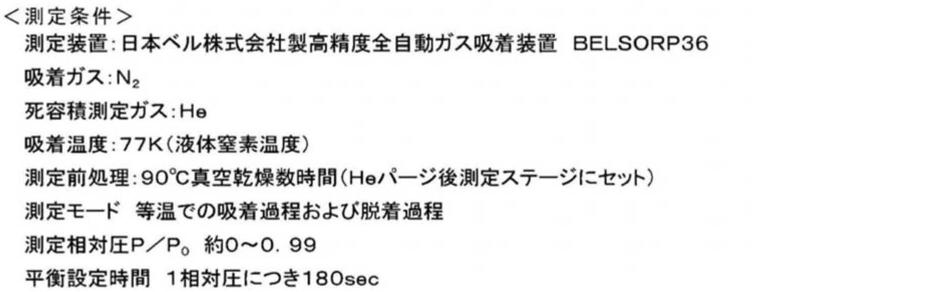
触媒金属は、電気的化学反応の触媒作用をする機能を有する。
触媒粒子を、下記条件によりX線回折(X-ray diffraction)(XRD)を行い、XRDパターンを得る。得られたXRDパターンにおいて、2θ値が39~41°の範囲に観測されるピーク面積(Ia)および31~34°の範囲に観測されるピーク面積(Ib)を測定する。ここで、2θ値が39~41°の範囲に観測されるピークは、白金部分もしくは合金部分の(111)由来のピークである。また、2θ値が31~34°の範囲に観測されるピークは、合金微粒子のL12構造に固有のピークである。
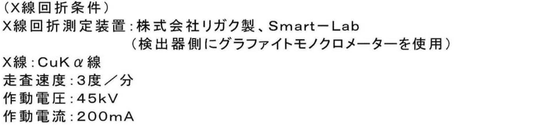


触媒担体の材質は、メソ孔を有し、メソ孔のモード径が1nm以上2.5nm未満となる空孔を担体の内部に形成することができ、触媒成分をメソ孔内部に分散状態で担持させるのに充分な比表面積と充分な電子伝導性とを有するものであれば特に制限されない。好ましくは、触媒担体は主成分がカーボンである。好適には、後述のように、特開2010-208887号公報(米国特許出願公開第2011/318254号明細書、以下同様)や国際公開第2009/075264号(米国特許出願公開第2011/058308号明細書、以下同様)などの公報に記載される方法を用いて製造された担体を出発原料として、これに白金および非白金金属を担持したものを電極触媒とすることが好ましい。その他、主成分がカーボンであるものとしては、具体的には、アセチレンブラック、チャンネルブラック、オイルファーネスブラック、ガスファーネスブラック(例えば、バルカン)、ランプブラック、サーマルブラック、ケッチェンブラック(登録商標)などのカーボンブラック;ブラックパール(登録商標);黒鉛化アセチレンブラック;黒鉛化チャンネルブラック;黒鉛化オイルファーネスブラック;黒鉛化ガスファーネスブラック;黒鉛化ランプブラック;黒鉛化サーマルブラック;黒鉛化ケッチェンブラック;黒鉛化ブラックパール;カーボンナノチューブ;カーボンナノファイバー;カーボンナノホーン;カーボンフィブリル;活性炭;コークス;天然黒鉛;人造黒鉛などを挙げることができる。「主成分がカーボンである」とは、主成分として炭素原子を含むことをいい、炭素原子のみからなる、実質的に炭素原子からなる、の双方を含む概念であり、炭素原子以外の元素が含まれていてもよい。「実質的に炭素原子からなる」とは、2~3重量%程度以下の不純物の混入が許容されうることを意味する。
電極触媒の製造方法は特に限定されるものではないが、白金粒子を担体に担持した後、該白金粒子に対して非白金金属を担持・合金化することが好ましい。
工程(1)は、担体および白金前駆体を含む混合液に還元剤を添加して白金粒子担持担体を調製する工程である。
工程(A)は担体を親水化処理する工程である。このような親水化処理により、非白金金属前駆体のメソ孔への導入が促進され、メソ孔内の触媒粒子が均一に合金化した合金粒子を形成することができ、触媒活性を向上させることができる。
工程(2)は、親水化処理された白金粒子担持担体および非白金金属前駆体を混合し、さらに合金化処理を施す工程である。
本発明の他の実施形態は、第一実施形態の電極触媒を含む膜電極接合体および燃料電池である。第一実施形態の電極触媒の電極触媒は、少ない白金含有量であっても、高い活性(面積比活性(単位面積当たりの活性)、質量比活性(質量当たりの活性))を発揮できる。このため、第一実施形態の電極触媒を触媒層に用いた膜電極接合体および燃料電池は、発電性能に優れる。
MEAは、電解質膜、上記電解質膜の両面に順次形成されるアノード触媒層およびアノードガス拡散層ならびにカソード触媒層およびカソードガス拡散層から構成される。そしてこの電解質膜-電極接合体において、カソード触媒層およびアノード触媒層の少なくとも一方に第一実施形態の電極触媒が使用される。
触媒層は、電極触媒および電解質を含む。
電解質膜は、例えば、固体高分子電解質膜から構成される。この固体高分子電解質膜は、例えば、燃料電池(PEFC等)の運転時にアノード触媒層で生成したプロトンを膜厚方向に沿ってカソード触媒層へと選択的に透過させる機能を有する。また、固体高分子電解質膜は、アノード側に供給される燃料ガスとカソード側に供給される酸化剤ガスとを混合させないための隔壁としての機能をも有する。
ガス拡散層(アノードガス拡散層4a、カソードガス拡散層4c)は、セパレータのガス流路(6a、6c)を介して供給されたガス(燃料ガスまたは酸化剤ガス)の触媒層(3a、3c)への拡散を促進する機能、および電子伝導パスとしての機能を有する。
電解質膜-電極接合体の作製方法としては、特に制限されず、従来公知の方法を使用できる。例えば、電解質膜に触媒層をホットプレスで転写または塗布し、これを乾燥したものに、ガス拡散層を接合する方法や、ガス拡散層のマイクロポーラス層側(マイクロポーラス層を含まない場合には、基材層の片面)に触媒層を予め塗布して乾燥することによりガス拡散電極(GDE)を2枚作製し、固体高分子電解質膜の両面にこのガス拡散電極をホットプレスで接合する方法を使用することができる。ホットプレス等の塗布、接合条件は、固体高分子電解質膜や触媒層内の高分子電解質の種類(パ-フルオロスルホン酸系や炭化水素系)によって適宜調整すればよい。
セパレータは、固体高分子形燃料電池などの燃料電池の単セルを複数個直列に接続して燃料電池スタックを構成する際に、各セルを電気的に直列に接続する機能を有する。また、セパレータは、燃料ガス、酸化剤ガス、および冷却剤を互に分離する隔壁としての機能も有する。これらの流路を確保するため、上述したように、セパレータのそれぞれにはガス流路および冷却流路が設けられていることが好ましい。セパレータを構成する材料としては、緻密カーボングラファイト、炭素板などのカーボンや、ステンレスなどの金属など、従来公知の材料が適宜制限なく採用できる。セパレータの厚さやサイズ、設けられる各流路の形状やサイズなどは特に限定されず、得られる燃料電池の所望の出力特性などを考慮して適宜決定できる。
国際公開第2009/075264号に記載の方法により、担体Aを作製した。担体Aは、比表面積が1570m2/g、メソ孔の空孔分布のモード半径が1.2nm、メソ孔の空孔容積が0.73cc/gであった。
合成例1で作製した担体Aを、アルゴン雰囲気下で1800℃にまで加熱した後、この温度で8分間保持した。
5nmの平均結晶子サイズを有する酸化マグネシウムと熱可塑性樹脂を、2:8の重量比で混合した複合物を窒素雰囲気900℃で熱処理したのち、得られたものを希硫酸で洗浄、乾燥することで担体Cを作製した。担体Cは、比表面積が1600m2/g、メソ孔のモード径が2.4nm、メソ孔の空孔容積が0.87cc/gであった。
10nmの平均結晶子サイズを有する酸化マグネシウムと熱可塑性樹脂を、3:7の重量比で混合した複合物を窒素雰囲気900℃で熱処理したのち、得られたものを希硫酸で洗浄、乾燥することで担体Dを作製した。担体Dは、比表面積が1300m2/g、メソ孔のモード径が6.1nm、メソ孔の空孔容積が0.45cc/gであった。
1.工程(1):白金粒子担持担体の作製
白金濃度0.8重量%のジニトロジアンミン白金硝酸水溶液1000g(白金含有量:8g)に、担体Aを19g浸漬させ、撹拌後、還元剤として100%メタノールを100ml添加した。この溶液を沸点(約95℃)で7時間、撹拌、混合し、白金を担体に担持させた。そして、濾過、乾燥することにより白金粒子担持担体を得た。この白金粒子担持担体の白金担持濃度(担持量)は、担体に対して、24.5重量%であった。担持濃度はICP分析により測定した。
1.0mol/Lの硝酸水溶液2Lに上記で得られた白金粒子担持担体20g添加し、撹拌後、撹拌を維持しながら、95℃にて2時間加熱した。加熱処理した後、室温まで冷却して親水化処理白金粒子担持担体液を得た(親水基結合量1.2mmol/g)。
上記で得られた親水化処理白金粒子担持担体液に水酸化ナトリウムを加えpHを2とした後、コバルト前駆体(硫酸コバルト、コバルト含有量1.6g)を投入した。これに、別途調製した還元剤溶液(水素化ホウ素ナトリウム10gを純水1Lに溶解)を全量投入し、室温で1時間、スターラーで撹拌・混合し、還元析出させた。そして、濾過、乾燥後、100体積%水素ガス中で、800℃、1時間の合金化処理を行うことで、電極触媒を製造した。この電極触媒の触媒金属の担持濃度(担持量)は、担体に対して、30.6重量%(Pt:29.0重量%、Co:1.6重量%)であった。
実施例1の工程(1)において、担体Aの代わりに担体Bを用いたこと以外は実施例1の工程(1)と同様にして白金粒子担持担体を得た。これを100体積%水素ガス中で、温度900℃に1時間保持して、得られた担体を白金粒子担持担体として用いた。この白金粒子担持担体の白金担持濃度(担持量)は、担体に対して、29.7重量%であった。得られた白金粒子担持担体に実施例1と同様にして親水化処理を行い、親水化処理白金粒子担持担体を得た。
実施例2の工程(1)において、白金濃度0.8重量%のジニトロジアミン白金硝酸水溶液を1000g(白金含有量:8g)に、担体Bを8g浸漬させて白金粒子担持担体(白金担持濃度(担持量) 担体に対して、49.4重量%)を得たこと以外は実施例2と同様にして電極触媒を製造した。この電極触媒の触媒金属の担持濃度(担持量)は、担体に対して、54.4重量%(Pt:49.3重量%、Co:5.1重量%)であった。
実施例3で得られた電極触媒に対して、水素ガス雰囲気下で、600℃で120分間、熱処理工程を実施した。この電極触媒について、規則度を測定したところ、49%であった。また、この電極触媒の触媒金属の担持濃度(担持量)は、担体に対して、58.1重量%(Pt:52.7重量%、Co:5.4重量%)であった。
実施例1において、親水化処理を行わなかったこと以外は、実施例1と同様にして電極触媒を製造した。この電極触媒の触媒金属の担持濃度(担持量)は、担体に対して、29.6重量%(Pt:27.7重量%、Co:1.9重量%)であった。
実施例1の工程(1)において得られた白金粒子担持担体を、100体積%水素ガス中で、温度900℃に1時間保持して、得られた白金粒子担持担体を電極触媒として用いた。この白金粒子担持担体の白金担持濃度(担持量)は、担体に対して、30.4重量%であった。
合成例3で作製した12gの担体Cを、白金を含む溶液に浸漬し、撹拌した。次いで、この溶液を、沸点(約95℃)で7時間撹拌、混合した後、ろ過、乾燥を行うことで、白金粒子担持担体を調製した。この際、用いた白金を含む溶液は、白金濃度0.8重量%のジニトロジアンミン白金硝酸溶液1000g(白金含有量:8g)である。
合成例4で作製した担体Dを用いたこと以外は、比較例3と同様にして触媒を製造した。この電極触媒の触媒金属の担持濃度(担持量)は、担体に対して、30.6重量%(Pt:27.8重量%、Co:2.8重量%)であった。
1.性能評価用回転電極(RDE)の作製
実施例及び比較例の電極触媒を、それぞれ、直径5mmのグラッシーカーボンディスクにより構成される回転ディスク電極(幾何面積:0.19cm2)上に白金の単位面積当たりの担持量が34μg/cm2となるように均一にNafionと共に分散担持し、性能評価用電極を作製した。
上記で作製した各触媒粉末と、高分子電解質としてのアイオノマ分散液(Nafion(登録商標)D2020,EW=1100g/eq(g/mol)、DuPont社製)とを、カーボン担体に対する高分子電解質の重量比が0.9となるよう混合した。さらに、水:n-プロピルアルコール=6:4(重量比)である溶媒を固形分率(Pt+カーボン担体+高分子電解質)が7重量%となるよう添加して、カソード触媒インクを調製した。
各膜電極接合体について、下記評価条件下、0.9V時の合金重量当たり発電電流(μA/g(Pt))を測定し、酸素還元活性評価を行った。

白金表面積あたりの面積比活性は、質量比活性の測定と同様の条件下で、電位が0.9Vの電流値を計測し、これを触媒有効表面積で除することにより値を得た。なお、触媒有効表面積の測定は、表2に示す条件のもとに測定対象の電位を掃引し、触媒金属に対するプロトンの吸着による電気量から算出した。

各実施例及び比較例の性能評価用回転電極(RDE)に対して、N2ガスで飽和した25℃の0.1M過塩素酸中において、可逆水素電極(RHE)に対して0.05~1.2Vの電位範囲で、50mVs-1の走査速度でサイクリックボルタンメトリーを行った。得られたボルタモグラムの0.05~0.4Vに現れる水素吸着ピークの面積より、各電極触媒の電気化学的表面積(cm2)を算出した。


Claims (8)
- 触媒金属が触媒担体に担持されてなる電極触媒であって、
前記触媒金属は、白金および白金以外の金属成分を含み、
半径が1nm以上であるメソ孔を有し、該メソ孔の空孔分布のモード半径が1nm以上2.5nm未満であり、
前記メソ孔内に白金および白金以外の金属成分の合金微粒子が担持され、メソ孔内に担持される合金微粒子における白金以外の金属成分に対する白金の含有モル比が1.0~10.0である、電極触媒。 - 前記メソ孔の空孔容積が0.4cc/g担体以上である、請求項1に記載の電極触媒。
- 前記メソ孔内に担持される合金微粒子の平均径が2.0nm以上である、請求項1または2に記載の電極触媒。
- 電極触媒中の合金微粒子が、内部構造として白金原子および白金以外の金属原子が規則正しく配列した金属間化合物構造を有する、請求項1~3のいずれか1項に記載の電極触媒。
- 電極触媒中の合金微粒子が、L12構造を有し、L12構造の規則度(Extent of ordering)が30~100%である、請求項4に記載の電極触媒。
- 前記白金以外の金属成分がコバルト(Co)である、請求項1~5のいずれか1項に記載の電極触媒。
- 請求項1~6のいずれか1項に記載の電極触媒および電解質を含む、膜電極接合体。
- 請求項7に記載の膜電極接合体を含む、燃料電池。
Priority Applications (6)
| Application Number | Priority Date | Filing Date | Title |
|---|---|---|---|
| US16/094,562 US10562018B2 (en) | 2016-04-19 | 2017-04-06 | Electrode catalyst, and membrane electrode assembly and fuel cell using electrode catalyst |
| EP17785817.2A EP3446781B1 (en) | 2016-04-19 | 2017-04-06 | Electrocatalyst, membrane electrode assembly using said electrocatalyst, and fuel cell |
| JP2018513107A JP6628867B2 (ja) | 2016-04-19 | 2017-04-06 | 電極触媒ならびに当該電極触媒を用いる膜電極接合体および燃料電池 |
| CN201780024342.9A CN109070064B (zh) | 2016-04-19 | 2017-04-06 | 电极催化剂以及使用该电极催化剂的膜电极接合体及燃料电池 |
| CA3021498A CA3021498C (en) | 2016-04-19 | 2017-04-06 | High activity alloy-based electrode catalyst, and membrane electrode assembly and fuel cell using high activity alloy-based electrode catalyst |
| KR1020187030285A KR102076926B1 (ko) | 2016-04-19 | 2017-04-06 | 전극 촉매 그리고 당해 전극 촉매를 사용하는 막 전극 접합체 및 연료 전지 |
Applications Claiming Priority (2)
| Application Number | Priority Date | Filing Date | Title |
|---|---|---|---|
| JP2016-083843 | 2016-04-19 | ||
| JP2016083843 | 2016-04-19 |
Publications (1)
| Publication Number | Publication Date |
|---|---|
| WO2017183475A1 true WO2017183475A1 (ja) | 2017-10-26 |
Family
ID=60116800
Family Applications (1)
| Application Number | Title | Priority Date | Filing Date |
|---|---|---|---|
| PCT/JP2017/014415 Ceased WO2017183475A1 (ja) | 2016-04-19 | 2017-04-06 | 電極触媒ならびに当該電極触媒を用いる膜電極接合体および燃料電池 |
Country Status (7)
| Country | Link |
|---|---|
| US (1) | US10562018B2 (ja) |
| EP (1) | EP3446781B1 (ja) |
| JP (1) | JP6628867B2 (ja) |
| KR (1) | KR102076926B1 (ja) |
| CN (1) | CN109070064B (ja) |
| CA (1) | CA3021498C (ja) |
| WO (1) | WO2017183475A1 (ja) |
Cited By (2)
| Publication number | Priority date | Publication date | Assignee | Title |
|---|---|---|---|---|
| DE102022105062A1 (de) | 2021-03-04 | 2022-09-08 | Cataler Corporation | Elektrokatalysator |
| KR20240149981A (ko) | 2022-03-04 | 2024-10-15 | 닛신보 홀딩스 가부시키 가이샤 | 금속담지촉매, 전극 및 전지 |
Families Citing this family (13)
| Publication number | Priority date | Publication date | Assignee | Title |
|---|---|---|---|---|
| CN109804491B (zh) * | 2016-10-05 | 2022-05-24 | 三井金属矿业株式会社 | 电极催化剂的制造方法以及电极催化剂 |
| CN109921045B (zh) * | 2017-12-12 | 2021-07-20 | 中国科学院大连化学物理研究所 | 一种以铂黑为载体的氧电极催化剂的制备与应用 |
| WO2020138800A1 (ko) * | 2018-12-26 | 2020-07-02 | 코오롱인더스트리 주식회사 | 촉매, 이의 제조 방법, 이를 포함하는 전극, 이를 포함하는 막-전극 어셈블리, 및 이를 포함하는 연료 전지 |
| JP6931808B1 (ja) | 2019-12-12 | 2021-09-08 | パナソニックIpマネジメント株式会社 | 燃料電池用の電極触媒、燃料電池の電極触媒層、膜/電極接合体および燃料電池 |
| KR102855179B1 (ko) * | 2020-03-13 | 2025-09-03 | 현대자동차주식회사 | 용출된 전이금속이 제거된 연료전지용 촉매 잉크의 제조방법 |
| US11705558B2 (en) * | 2020-06-19 | 2023-07-18 | Robert Bosch Gmbh | Patterned catalyst layers in fuel cells |
| CN116322993B (zh) * | 2020-09-29 | 2026-03-20 | 恩亿凯嘉股份有限公司 | 电极用催化剂、气体扩散电极形成用组合物、气体扩散电极、膜-电极接合体以及燃料电池堆 |
| CN116390810B (zh) * | 2020-09-29 | 2026-03-20 | 恩亿凯嘉股份有限公司 | 电极用催化剂、气体扩散电极形成用组合物、气体扩散电极、膜-电极接合体以及燃料电池堆 |
| JP7072040B1 (ja) * | 2020-12-10 | 2022-05-19 | 株式会社キャタラー | 燃料電池用触媒及びその製造方法 |
| KR20220091754A (ko) * | 2020-12-24 | 2022-07-01 | 현대자동차주식회사 | 인터메탈릭 촉매 및 이의 제조 방법 |
| KR20220103288A (ko) * | 2021-01-15 | 2022-07-22 | 현대자동차주식회사 | 인터메탈릭 촉매 및 이의 제조 방법 |
| JP7738275B2 (ja) | 2021-03-19 | 2025-09-12 | パナソニックIpマネジメント株式会社 | 電極触媒を用いる電極触媒層、膜/電極接合体および電気化学デバイス |
| CN114005995B (zh) * | 2021-11-01 | 2023-11-10 | 天津理工大学 | 一种柔性金属电极的制备方法 |
Citations (9)
| Publication number | Priority date | Publication date | Assignee | Title |
|---|---|---|---|---|
| JP2005135817A (ja) * | 2003-10-31 | 2005-05-26 | Nittetsu Gijutsu Joho Center:Kk | 燃料電池用電極触媒 |
| JP2006228502A (ja) * | 2005-02-16 | 2006-08-31 | Mitsui Chemicals Inc | 燃料電池用電極触媒とその製造方法およびそれを用いた電極と燃料電池 |
| WO2007055411A1 (ja) * | 2005-11-14 | 2007-05-18 | Cataler Corporation | 燃料電池用触媒、燃料電池用電極、及びこれを備えた固体高分子型燃料電池 |
| JP2008290062A (ja) * | 2007-04-25 | 2008-12-04 | Kansai Coke & Chem Co Ltd | 触媒担体、触媒、触媒担体の製造方法、および触媒の製造方法 |
| JP2008311055A (ja) * | 2007-06-14 | 2008-12-25 | Asahi Kasei Corp | 非白金系燃料電池用電極および燃料電池 |
| JP2010198885A (ja) * | 2009-02-24 | 2010-09-09 | Ishifuku Metal Ind Co Ltd | 燃料電池用白金規則格子触媒及びその製造方法 |
| WO2014175106A1 (ja) * | 2013-04-25 | 2014-10-30 | 日産自動車株式会社 | 電極、並びにこれを含む燃料電池用電極触媒層 |
| WO2014175100A1 (ja) * | 2013-04-25 | 2014-10-30 | 日産自動車株式会社 | 触媒ならびに当該触媒を用いる電極触媒層、膜電極接合体および燃料電池 |
| JP2015204216A (ja) * | 2014-04-15 | 2015-11-16 | トヨタ自動車株式会社 | 燃料電池用電極触媒、及び燃料電池用電極触媒の製造方法 |
Family Cites Families (11)
| Publication number | Priority date | Publication date | Assignee | Title |
|---|---|---|---|---|
| WO2002003489A1 (en) * | 2000-07-03 | 2002-01-10 | Matsushita Electric Industrial Co., Ltd. | Polyelectrolyte fuel cell |
| US8486551B2 (en) * | 2005-09-29 | 2013-07-16 | Micro Silitron Inc. | Fuel cell unit, fuel cell unit array, fuel cell module and fuel cell system |
| JP2007335338A (ja) * | 2006-06-19 | 2007-12-27 | Toyota Motor Corp | 燃料電池用電極触媒の製造方法、燃料電池用電極触媒、及びこれを備えた固体高分子型燃料電池 |
| US7670988B2 (en) * | 2006-10-17 | 2010-03-02 | Stc, Unm | Nanostructured anode PT-RU electrocatalysts for direct methanol fuel cells |
| JP4880064B1 (ja) | 2010-12-08 | 2012-02-22 | 田中貴金属工業株式会社 | 固体高分子形燃料電池用触媒及びその製造方法 |
| FI124743B (fi) | 2012-10-18 | 2015-01-15 | Wärtsilä Finland Oy | Polttoaineen ruiskutusjärjestely |
| US10573901B2 (en) * | 2013-04-25 | 2020-02-25 | Tanaka Kikinzoku Kogyo K.K. | Catalyst and manufacturing method thereof, and electrode catalyst layer using the catalyst |
| CN105142784A (zh) * | 2013-04-25 | 2015-12-09 | 日产自动车株式会社 | 催化剂以及使用该催化剂的电极催化剂层、膜电极接合体及燃料电池 |
| CN105142778B (zh) * | 2013-04-25 | 2017-11-10 | 日产自动车株式会社 | 催化剂以及使用该催化剂的电极催化剂层、膜电极接合体及燃料电池 |
| EP2990105B1 (en) * | 2013-04-25 | 2018-11-21 | Nissan Motor Co., Ltd | Catalyst, and electrode catalyst layer, film electrode assembly, and fuel cell each including said catalyst |
| CN105594035B (zh) | 2013-08-09 | 2018-07-06 | 日产自动车株式会社 | 催化剂颗粒及使用其的电极催化剂、电解质膜-电极接合体和燃料电池 |
-
2017
- 2017-04-06 EP EP17785817.2A patent/EP3446781B1/en active Active
- 2017-04-06 WO PCT/JP2017/014415 patent/WO2017183475A1/ja not_active Ceased
- 2017-04-06 JP JP2018513107A patent/JP6628867B2/ja active Active
- 2017-04-06 CN CN201780024342.9A patent/CN109070064B/zh active Active
- 2017-04-06 US US16/094,562 patent/US10562018B2/en active Active
- 2017-04-06 CA CA3021498A patent/CA3021498C/en active Active
- 2017-04-06 KR KR1020187030285A patent/KR102076926B1/ko active Active
Patent Citations (9)
| Publication number | Priority date | Publication date | Assignee | Title |
|---|---|---|---|---|
| JP2005135817A (ja) * | 2003-10-31 | 2005-05-26 | Nittetsu Gijutsu Joho Center:Kk | 燃料電池用電極触媒 |
| JP2006228502A (ja) * | 2005-02-16 | 2006-08-31 | Mitsui Chemicals Inc | 燃料電池用電極触媒とその製造方法およびそれを用いた電極と燃料電池 |
| WO2007055411A1 (ja) * | 2005-11-14 | 2007-05-18 | Cataler Corporation | 燃料電池用触媒、燃料電池用電極、及びこれを備えた固体高分子型燃料電池 |
| JP2008290062A (ja) * | 2007-04-25 | 2008-12-04 | Kansai Coke & Chem Co Ltd | 触媒担体、触媒、触媒担体の製造方法、および触媒の製造方法 |
| JP2008311055A (ja) * | 2007-06-14 | 2008-12-25 | Asahi Kasei Corp | 非白金系燃料電池用電極および燃料電池 |
| JP2010198885A (ja) * | 2009-02-24 | 2010-09-09 | Ishifuku Metal Ind Co Ltd | 燃料電池用白金規則格子触媒及びその製造方法 |
| WO2014175106A1 (ja) * | 2013-04-25 | 2014-10-30 | 日産自動車株式会社 | 電極、並びにこれを含む燃料電池用電極触媒層 |
| WO2014175100A1 (ja) * | 2013-04-25 | 2014-10-30 | 日産自動車株式会社 | 触媒ならびに当該触媒を用いる電極触媒層、膜電極接合体および燃料電池 |
| JP2015204216A (ja) * | 2014-04-15 | 2015-11-16 | トヨタ自動車株式会社 | 燃料電池用電極触媒、及び燃料電池用電極触媒の製造方法 |
Cited By (3)
| Publication number | Priority date | Publication date | Assignee | Title |
|---|---|---|---|---|
| DE102022105062A1 (de) | 2021-03-04 | 2022-09-08 | Cataler Corporation | Elektrokatalysator |
| US11901568B2 (en) | 2021-03-04 | 2024-02-13 | Toyota Jidosha Kabushiki Kaisha | Electrocatalyst |
| KR20240149981A (ko) | 2022-03-04 | 2024-10-15 | 닛신보 홀딩스 가부시키 가이샤 | 금속담지촉매, 전극 및 전지 |
Also Published As
| Publication number | Publication date |
|---|---|
| CN109070064A (zh) | 2018-12-21 |
| EP3446781A4 (en) | 2019-03-27 |
| US20190336956A1 (en) | 2019-11-07 |
| CN109070064B (zh) | 2020-07-28 |
| EP3446781A1 (en) | 2019-02-27 |
| CA3021498A1 (en) | 2017-10-26 |
| CA3021498C (en) | 2019-12-17 |
| JPWO2017183475A1 (ja) | 2019-02-28 |
| KR20180128938A (ko) | 2018-12-04 |
| JP6628867B2 (ja) | 2020-01-15 |
| EP3446781B1 (en) | 2020-09-09 |
| KR102076926B1 (ko) | 2020-02-12 |
| US10562018B2 (en) | 2020-02-18 |
Similar Documents
| Publication | Publication Date | Title |
|---|---|---|
| JP6628867B2 (ja) | 電極触媒ならびに当該電極触媒を用いる膜電極接合体および燃料電池 | |
| JP5998277B2 (ja) | 燃料電池用触媒、およびこれを含む燃料電池用電極触媒層 | |
| JP6461805B2 (ja) | 触媒用炭素粉末ならびに当該触媒用炭素粉末を用いる触媒、電極触媒層、膜電極接合体および燃料電池 | |
| CA2910237C (en) | Catalyst and manufacturing method thereof, and electrode catalyst layer using the catalyst | |
| JP6113837B2 (ja) | 触媒ならびに当該触媒を用いる電極触媒層、膜電極接合体および燃料電池 | |
| JP5998275B2 (ja) | 燃料電池用触媒ならびに当該燃料電池用触媒を用いる電極触媒層、膜電極接合体および燃料電池 | |
| JP6172281B2 (ja) | 触媒粒子ならびにこれを用いる電極触媒、電解質膜−電極接合体および燃料電池 | |
| JP6327681B2 (ja) | 燃料電池用電極触媒、その製造方法、当該触媒を含む燃料電池用電極触媒層ならびに当該触媒または触媒層を用いる燃料電池用膜電極接合体および燃料電池 | |
| JP6008044B2 (ja) | 燃料電池用触媒ならびに当該燃料電池用触媒を用いる電極触媒層、膜電極接合体および燃料電池 | |
| JP6323818B2 (ja) | 燃料電池用電極触媒、燃料電池用電極触媒層、その製造方法ならびに当該触媒層を用いる膜電極接合体および燃料電池 | |
| JP5998276B2 (ja) | 触媒の製造方法ならびに当該触媒を用いる電極触媒層、膜電極接合体および燃料電池 | |
| JP2016054065A (ja) | 電極触媒の製造方法 | |
| JP6191368B2 (ja) | 燃料電池用膜電極接合体および燃料電池 | |
| JP6183120B2 (ja) | 燃料電池用膜電極接合体および燃料電池 | |
| JP6672622B2 (ja) | 燃料電池用電極触媒層およびその製造方法、ならびに当該触媒層を用いる膜電極接合体、燃料電池および車両 | |
| JP6846210B2 (ja) | 電極触媒ならびに当該電極触媒を用いる膜電極接合体および燃料電池 |
Legal Events
| Date | Code | Title | Description |
|---|---|---|---|
| ENP | Entry into the national phase |
Ref document number: 2018513107 Country of ref document: JP Kind code of ref document: A |
|
| ENP | Entry into the national phase |
Ref document number: 3021498 Country of ref document: CA |
|
| ENP | Entry into the national phase |
Ref document number: 20187030285 Country of ref document: KR Kind code of ref document: A |
|
| NENP | Non-entry into the national phase |
Ref country code: DE |
|
| WWE | Wipo information: entry into national phase |
Ref document number: 2017785817 Country of ref document: EP |
|
| ENP | Entry into the national phase |
Ref document number: 2017785817 Country of ref document: EP Effective date: 20181119 |
|
| 121 | Ep: the epo has been informed by wipo that ep was designated in this application |
Ref document number: 17785817 Country of ref document: EP Kind code of ref document: A1 |