WO2017183654A1 - 無線端末及び基地局 - Google Patents
無線端末及び基地局 Download PDFInfo
- Publication number
- WO2017183654A1 WO2017183654A1 PCT/JP2017/015703 JP2017015703W WO2017183654A1 WO 2017183654 A1 WO2017183654 A1 WO 2017183654A1 JP 2017015703 W JP2017015703 W JP 2017015703W WO 2017183654 A1 WO2017183654 A1 WO 2017183654A1
- Authority
- WO
- WIPO (PCT)
- Prior art keywords
- specific
- cell
- bearer
- control unit
- lcg
- Prior art date
- Legal status (The legal status is an assumption and is not a legal conclusion. Google has not performed a legal analysis and makes no representation as to the accuracy of the status listed.)
- Ceased
Links
Images




Classifications
-
- H—ELECTRICITY
- H04—ELECTRIC COMMUNICATION TECHNIQUE
- H04W—WIRELESS COMMUNICATION NETWORKS
- H04W76/00—Connection management
- H04W76/10—Connection setup
- H04W76/11—Allocation or use of connection identifiers
-
- H—ELECTRICITY
- H04—ELECTRIC COMMUNICATION TECHNIQUE
- H04W—WIRELESS COMMUNICATION NETWORKS
- H04W72/00—Local resource management
- H04W72/04—Wireless resource allocation
-
- H—ELECTRICITY
- H04—ELECTRIC COMMUNICATION TECHNIQUE
- H04W—WIRELESS COMMUNICATION NETWORKS
- H04W16/00—Network planning, e.g. coverage or traffic planning tools; Network deployment, e.g. resource partitioning or cells structures
- H04W16/14—Spectrum sharing arrangements between different networks
-
- H—ELECTRICITY
- H04—ELECTRIC COMMUNICATION TECHNIQUE
- H04W—WIRELESS COMMUNICATION NETWORKS
- H04W76/00—Connection management
- H04W76/10—Connection setup
- H04W76/12—Setup of transport tunnels
Definitions
- the present disclosure relates to a radio terminal and a base station used in a mobile communication system.
- 3GPP Third Generation Partnership Project
- carrier aggregation a technology for wireless terminals to communicate with base stations simultaneously using multiple cells (ie, multiple component carriers), has been specified. Yes.
- the maximum number of cells for carrier aggregation (that is, the maximum number of cells to be aggregated) is 5.
- the maximum number of cells for carrier aggregation is expanded to 32. Therefore, in the future, it is considered that a plurality of cells to be aggregated do not have similar characteristics, but cells having various characteristics can be aggregated.
- a wireless terminal communicates with a base station by simultaneously using a plurality of cells including a LAA (Licensed Assisted Access) cell.
- the wireless terminal includes a control unit that performs a process of receiving setting information from the base station for setting whether to permit transmission of data on a specific LC (Logical Channel) of the wireless terminal on the LAA cell.
- LC Logical Channel
- a base station communicates with a wireless terminal by simultaneously using a plurality of cells including a LAA (Licensed Assisted Access) cell.
- the base station includes a control unit that performs a process of transmitting setting information for setting whether to permit transmission of data on a specific LC (Logical Channel) of the wireless terminal on the LAA cell to the wireless terminal.
- LC Logical Channel
- a wireless terminal communicates with a base station using a plurality of cells simultaneously.
- the wireless terminal includes a control unit that performs a process of receiving, from the base station, an association setting for setting an association between a specific bearer or a specific LCG (Logical Channel Group) of the wireless terminal and one or a plurality of specific cells. .
- the control unit associates the specific bearer or the specific LCG with the one or more specific cells based on the association setting.
- a base station communicates with a wireless terminal using a plurality of cells simultaneously.
- the base station includes a control unit that generates an association setting for setting an association between a specific bearer or a specific LCG (Logical Channel Group) of the wireless terminal and one or a plurality of specific cells.
- the said control part performs the process which transmits the said matching setting to the said radio
- FIG. 1 is a diagram illustrating a configuration of an LTE (Long Term Evolution) system that is a mobile communication system according to an embodiment.
- the LTE system is a mobile communication system based on the 3GPP standard.
- the LTE system includes a UE (User Equipment) 100, an E-UTRAN (Evolved-UMTS Terrestrial Radio Access Network) 10, and an EPC (Evolved Packet Core) 20.
- UE User Equipment
- E-UTRAN Evolved-UMTS Terrestrial Radio Access Network
- EPC Evolved Packet Core
- the UE 100 corresponds to a wireless terminal.
- the UE 100 is a mobile communication device.
- the UE 100 performs communication with a cell (serving cell).
- the E-UTRAN 10 corresponds to a radio access network.
- the E-UTRAN 10 includes an eNB 200 (evolved Node-B).
- the eNB 200 corresponds to a base station.
- the eNB 200 is connected to each other via the X2 interface.
- the eNB 200 manages one or a plurality of cells and performs radio communication with the UE 100 that has established a connection with the own cell.
- the eNB 200 has a radio resource management (RRM) function, a routing function of user data (hereinafter simply referred to as “data”), a measurement control function for mobility control / scheduling, and the like.
- RRM radio resource management
- Cell is used as a term indicating a minimum unit of a wireless communication area.
- Cell is also used as a term indicating a function of performing wireless communication with the UE 100.
- the EPC 20 corresponds to a core network.
- the EPC 20 includes an MME (Mobility Management Entity) / S-GW (Serving-Gateway) 300.
- MME Mobility Management Entity
- S-GW Serving-Gateway
- MME performs various mobility control etc. with respect to UE100.
- the S-GW performs data transfer control.
- the MME / S-GW 300 is connected to the eNB 200 via the S1 interface.
- FIG. 2 is a diagram illustrating a configuration of the UE 100 (wireless terminal). As illustrated in FIG. 2, the UE 100 includes a reception unit 110, a transmission unit 120, and a control unit 130.
- the receiving unit 110 performs various types of reception under the control of the control unit 130.
- the receiving unit 110 includes an antenna and a receiver.
- the receiver converts a radio signal received by the antenna into a baseband signal (received signal) and outputs the baseband signal to the control unit 130.
- the transmission unit 120 performs various transmissions under the control of the control unit 130.
- the transmission unit 120 includes an antenna and a transmitter.
- the transmitter converts the baseband signal (transmission signal) output from the control unit 130 into a radio signal and transmits it from the antenna.
- the control unit 130 performs various controls in the UE 100.
- the control unit 130 includes a processor and a memory.
- the memory stores a program executed by the processor and information used for processing by the processor.
- the processor includes a baseband processor and a CPU (Central Processing Unit).
- the baseband processor performs modulation / demodulation and encoding / decoding of the baseband signal.
- the CPU performs various processes by executing programs stored in the memory.
- the processor executes processing to be described later.
- FIG. 3 is a diagram illustrating a configuration of the eNB 200 (base station). As illustrated in FIG. 3, the eNB 200 includes a transmission unit 210, a reception unit 220, a control unit 230, and a backhaul communication unit 240.
- the transmission unit 210 performs various transmissions under the control of the control unit 230.
- the transmission unit 210 includes an antenna and a transmitter.
- the transmitter converts the baseband signal (transmission signal) output from the control unit 230 into a radio signal and transmits it from the antenna.
- the receiving unit 220 performs various types of reception under the control of the control unit 230.
- the receiving unit 220 includes an antenna and a receiver.
- the receiver converts a radio signal received by the antenna into a baseband signal (received signal) and outputs the baseband signal to the control unit 230.
- the control unit 230 performs various controls in the eNB 200.
- the control unit 230 includes a processor and a memory.
- the memory stores a program executed by the processor and information used for processing by the processor.
- the processor includes a baseband processor and a CPU (Central Processing Unit).
- the baseband processor performs modulation / demodulation and encoding / decoding of the baseband signal.
- the CPU performs various processes by executing programs stored in the memory.
- the processor executes processing to be described later.
- the backhaul communication unit 240 is connected to the neighboring eNB 200 via the X2 interface.
- the backhaul communication unit 240 is connected to the MME / S-GW 300 via the S1 interface.
- the backhaul communication unit 240 is used for communication performed on the X2 interface, communication performed on the S1 interface, and the like.
- FIG. 4 is a diagram showing a configuration of a protocol stack of a radio interface in the LTE system.
- the radio interface protocol is divided into the first to third layers of the OSI reference model.
- the first layer is a physical (PHY) layer.
- the second layer includes a MAC (Medium Access Control) layer, an RLC (Radio Link Control) layer, and a PDCP (Packet Data Convergence Protocol) layer.
- the third layer includes an RRC (Radio Resource Control) layer.
- the physical layer performs encoding / decoding, modulation / demodulation, antenna mapping / demapping, and resource mapping / demapping. Data and control information are transmitted between the physical layer of the UE 100 and the physical layer of the eNB 200 via a physical channel.
- the MAC layer performs data priority control, retransmission processing by hybrid ARQ (HARQ), random access procedure, and the like. Data and control information are transmitted between the MAC layer of the UE 100 and the MAC layer of the eNB 200 via a transport channel.
- the MAC layer of the eNB 200 includes a scheduler. The scheduler determines the uplink / downlink transport format (transport block size, modulation / coding scheme (MCS)) and the resource blocks allocated to the UE 100.
- MCS modulation / coding scheme
- the RLC layer transmits data to the RLC layer on the receiving side using the functions of the MAC layer and the physical layer. Data and control information are transmitted between the RLC layer of the UE 100 and the RLC layer of the eNB 200 via a logical channel.
- the PDCP layer performs header compression / decompression and encryption / decryption.
- the RRC layer is defined only in the control plane that handles control information. Messages for various settings (RRC messages) are transmitted between the RRC layer of the UE 100 and the RRC layer of the eNB 200.
- the RRC layer controls the logical channel, the transport channel, and the physical channel according to establishment, re-establishment, and release of the radio bearer.
- RRC connection When there is a connection (RRC connection) between the RRC of the UE 100 and the RRC of the eNB 200, the UE 100 is in the RRC connected mode. Otherwise, the UE 100 is in RRC idle mode.
- the NAS (Non-Access Stratum) layer located above the RRC layer performs session management and mobility management.
- FIG. 5 is a diagram showing a configuration of a radio frame used in the LTE system.
- the radio frame is composed of 10 subframes arranged in the time direction.
- Each subframe is composed of two slots arranged in the time direction.
- the length of each subframe is 1 ms.
- the length of each slot is 0.5 ms.
- Each subframe includes a plurality of resource blocks (RB) in the frequency direction.
- Each subframe includes a plurality of symbols in the time direction.
- Each resource block includes a plurality of subcarriers in the frequency direction.
- One symbol and one subcarrier constitute one resource element (RE).
- a frequency resource can be specified by a resource block, and a time resource can be specified by a subframe (or slot).
- Carrier aggregation The carrier aggregation will be described.
- the mobile communication system according to the embodiment supports carrier aggregation.
- carrier aggregation a plurality of component carriers are aggregated to ensure a wide transmission bandwidth.
- the UE 100 performs transmission or reception simultaneously on a plurality of component carriers.
- the UE 100 in which carrier aggregation is set has one RRC connection with the network.
- one serving cell provides NAS mobility information to the UE 100.
- security information security input
- the one serving cell is referred to as a primary cell.
- the component carrier corresponding to the primary cell is referred to as a primary component carrier.
- the primary cell is changed by handover.
- a secondary cell is set together with the primary cell so as to form a set of serving cells.
- the component carrier corresponding to the secondary cell is referred to as a secondary component carrier.
- the number of serving cells that can be set depends on the carrier aggregation capability of the UE 100. Setting (addition) and removal of secondary cells are performed by the RRC layer (RRC entity).
- the activation and deactivation of the set secondary cell is performed by the MAC layer (MAC entity).
- the MAC entity of the eNB 200 activates / deactivates the set secondary cell by transmitting an activation / deactivation MAC control element to the UE 100.
- the primary cell cannot be deactivated.
- the MAC entity of the UE 100 has a deactivation timer set by the RRC entity.
- the MAC entity of the UE 100 starts a deactivation timer when the secondary cell is activated.
- the MAC entity of the UE 100 deactivates the secondary cell in response to expiration of the deactivation timer.
- a plurality of configured serving cells can be grouped into a timing advance group (TAG) consisting of cells having the same timing advance (TA).
- TAG timing advance group
- the UE 100 can perform simultaneous transmission / reception of a plurality of serving cells by applying different timing advance for each timing advance group.
- FIG. 6 is a diagram illustrating a second layer (layer 2) structure in the UE 100 in which carrier aggregation is set.
- layers 2 layers 2 structure
- operations related to the uplink will be mainly described.
- the PDCP entity and the RLC entity of the UE 100 process data of a plurality of radio bearers.
- the MAC entity processes data of a plurality of logical channels (Logical Channels) corresponding to a plurality of radio bearers.
- the maximum number of radio bearers (logical channels) is eight.
- the data radio bearer is added in ToAddModList of RadioResourceConfigDedicated which is a type of RRC signaling, and has an upper limit of eight. Signaling radio bearers are added in the same manner, and finally three signaling radio bearers are established.
- the MAC entity of the UE 100 groups a plurality of logical channels into four LCGs (Logical Channel Group).
- the MAC entity of the UE 100 manages the retention amount of data for each LCG as a buffer status, and transmits a buffer status report to the eNB 200.
- the data retention amount may be referred to as “mount of data available for transmission”.
- the MAC entity of the UE 100 performs prioritization (scheduling / priority handling) of a plurality of logical channels so as to preferentially transmit high priority logical channels using uplink radio resources allocated by the eNB 200.
- the MAC entity of the UE 100 multiplexes the data of the logical channels with priorities and provides the data to the physical layer entity through the HARQ entity.
- the transport block generated by each HARQ entity is associated with one serving cell. Such a procedure of the MAC entity is referred to as logical channel prioritization.
- the UE 100 has a connection with the master eNB and the secondary eNB, and performs communication using the cell group (master cell group) of the master eNB and the cell group (secondary cell group) of the secondary eNB at the same time.
- the UE 100 has an RRC connection only with the master eNB, and transmits and receives RRC signaling to and from the master eNB.
- the first to fourth embodiments are embodiments mainly related to “Logical channel prioritization” in carrier gregation.
- FIG. 7 is a diagram illustrating operations of the UE 100 and the eNB 200 according to the first embodiment.
- the UE 100 In the initial state of FIG. 7, the UE 100 is in a state where an RRC connection with the eNB 200 has been established (that is, RRC connected mode).
- the eNB 200 generates an association setting (Mapping configuration).
- the association setting sets the association between the specific bearer or specific LCG of the UE 100 and one or a plurality of specific cells.
- a bearer is a radio bearer (RB).
- the radio bearer may be a data radio bearer (DRB).
- the specific cell is a serving cell of the UE 100 and is a cell used for carrier aggregation.
- the specific cell may be a secondary cell set in the UE 100.
- the eNB 200 generates the association setting so that the characteristics of the secondary cell set in the UE 100 and the characteristics of the traffic (bearer or LCG) are matched.
- the cell characteristics include whether or not the cell is an unlicensed spectrum and / or cell load status (wireless load, backhaul load) and the like.
- An unlicensed spectrum cell may be referred to as an LAA (Licensed Assisted Access) cell.
- the traffic characteristic may be a QoS (Quality of Service) characteristic such as whether or not the traffic requires low delay.
- the eNB 200 can generate the association setting so that the bearer or the LCG for which high QoS is required is associated with the cell of the licensed spectrum.
- eNB200 can produce
- the eNB 200 transmits the association setting to the UE 100.
- the eNB 200 may transmit the association setting to the UE 100 by RRC signaling on the primary cell.
- the RRC signaling may be UE-specific RRC signaling (Dedicated signaling).
- the association setting may include a combination of a bearer ID and a cell ID or a combination of an LCG ID and a cell ID. Since bearers and logical channels have a one-to-one relationship, bearer IDs may be read as logical channel IDs.
- the eNB 200 sets (adds) a secondary cell to the UE 100, the eNB 200 may transmit the association setting including the bearer ID or the LCG ID associated with the secondary to the UE 100.
- step S102 the UE 100 receives the association setting from the eNB 200.
- the UE 100 associates its specific bearer or specific LCG with one or a plurality of specific cells based on the association setting.
- the MAC entity of the UE 100 may acquire a combination of the bearer ID and the cell ID included in the association setting from the RRC entity, and associate the bearer ID with the cell ID.
- the MAC entity of the UE 100 may acquire a combination of the LCG ID and the cell ID included in the association setting from the RRC entity, and associate the LCG indicated by the LCG ID with the cell indicated by the cell ID. .
- step S104 the eNB 200 and the UE 100 perform communication by carrier aggregation using a plurality of cells (a plurality of serving cells) simultaneously.
- UE100 transmits the data of a specific bearer or specific LCG on the 1 or several specific cell corresponding to the specific bearer or the specific LCG.
- the characteristics of the aggregated cell and the traffic characteristics can be matched. Further, since the number of LCGs “4” is half that of the number of bearers “8”, it is preferable to associate the LCG with the cell instead of the bearer. Thereby, compared with the case where a bearer is matched with a cell, the complexity of control and setting can be halved.
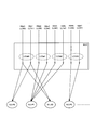
- FIG. 8 is a diagram illustrating an example of “Logical channel prioritization” according to the first embodiment.
- the radio bearer is expressed as RB
- the logical channel is expressed as LC.
- RB # 0 (LC # 0) and RB # 1 (LC # 1) belong to LCG # 0, and RB # 2 (LC # 2) and RB # 3 (LC # 3) belong to LCG RB # 4 (LC # 4) and RB # 5 (LC # 5) belong to LCG # 2, and RB # 6 (LC # 6) and RB # 7 (LC # 7) belong to LCG # 3 Belonging to.
- RB # 0 (LC # 0) and RB # 1 (LC # 1) belong to LCG # 0
- RB # 2 (LC # 2) and RB # 3 (LC # 3) belong to LCG RB # 4 (LC # 4) and RB # 5 (LC # 5) belong to LCG # 2
- RB # 6 (LC # 6) and RB # 7 (LC # 7) belong to LCG # 3 Belonging to.
- the association between the RB (LC) and the LCG is set by the eNB 200, it is not limited to the example of FIG.
- the MAC entity of the UE 100 performs processing of associating the LCG with the cell based on the association setting and transmitting the LCG data on the corresponding cell.
- the MAC entity of the UE 100 associates LCG # 0 with the cell # 0 and the cell # 2, and performs processing of transmitting the data of the LCG # 0 on the cell # 0 and the cell # 2.
- the MAC entity of the UE 100 associates LCG # 1 with cell # 1, and performs processing of transmitting LCG # 1 data on cell # 1.
- the MAC entity of UE 100 associates LCG # 2 with cell # 1, and performs processing for transmitting LCG # 2 data on cell # 1.
- the MAC entity of the UE 100 associates LCG # 3 with cell # 3, and performs processing of transmitting LCG # 3 data on cell # 3.
- one or more specific cells indicated by the association setting are cells (Allowed cells) that the UE 100 is allowed to use for transmission.
- cells Allowed cells
- a problem Radio problem
- one or more specific cells indicated by the association setting are cells (Prohibited cells) that the UE 100 is prohibited from using for transmission.
- the association setting sets an association between the specific bearer or the specific LCG of the UE 100 and one or a plurality of prohibited cells (Prohibited cells).
- UE100 prohibits transmitting the data of a specific bearer on the prohibition cell corresponding to the specific bearer based on the association setting. That is, UE100 transmits the data of a specific bearer on cells other than the prohibited cell corresponding to the specific bearer.
- UE100 prohibits transmitting the data of specific LCG on the prohibition cell corresponding to the said specific LCG based on an association setting. That is, UE100 transmits the data of specific LCG on cells other than the prohibition cell corresponding to the specific LCG.
- the cell other than the prohibited cell may be a serving cell autonomously selected by the UE 100.
- the eNB 200 generates an association setting so that a non-GBR (Guaranted Bit Rate) bearer such as web browsing does not use a licensed spectrum cell. Thereby, the load of the cell of a licensed spectrum can be reduced.
- the eNB 200 generates the association setting so that a bearer requiring high QoS such as an emergency VoLTE (Voice over LTE) call does not use an unlicensed spectrum cell (LAA cell). Thereby, it is possible to appropriately transmit bearer data for which high QoS is required.
- a bearer requiring high QoS such as an emergency VoLTE (Voice over LTE) call does not use an unlicensed spectrum cell (LAA cell).
- RRC connection reconfiguration for changing the association between a bearer (or LCG) and a cell by reusing an existing RLF (Radio Link Failure) mechanism.
- RLF Radio Link Failure
- a method of starting the eNB 200 is conceivable.
- the RRC connection reconfiguration may be performed by removing a cell in which a problem has occurred or adding a good cell to the association setting.
- the existing RLF mechanism only the primary cell is monitored, and the secondary cell is out of scope.
- the eNB 200 determines that the specific cell is not functioning when uplink transmission of the UE 100 is not performed after transmitting UL grant.
- the UE 100 includes one or a plurality of specific cells depending on whether a data retention amount (stacked data amount) or a data retention time (data stacked duration) exceeds a threshold set by the eNB 200. It is determined that a problem has occurred.
- the threshold may be set by UE dedicated RRC signaling or broadcast RRC signaling. Thereby, the problem which arose in the secondary cell can be detected rapidly, without depending on the structure of the existing RLF.
- the existing RLF mechanism may be extended to the secondary cell, and a problem occurring in the secondary cell may be detected by an RLM (Radio Link Monitoring) function.
- RLM Radio Link Monitoring
- an alternative cell is a cell determined by RRC configuration, a primary cell, a cell to which uplink resources are allocated (that is, a cell that has already transmitted UL grant), or a cell that UE 100 has autonomously selected. is there.
- UE100 may transmit the notification (indication) regarding the said problem to eNB200, when it judges that the problem had arisen in the specific cell. For example, the UE 100 transmits a notification on the primary cell.
- the notification may include the ID of the cell in which the problem has occurred, the ID of the bearer corresponding to the cell, or the ID of the LCG corresponding to the cell.
- FIG. 9 is a diagram illustrating an example of the operation of the UE 100 according to the second embodiment.
- the UE 100 receives a threshold setting from the eNB 200 by RRC signaling.
- the threshold value is a threshold value for the data retention amount or a threshold value for the data retention time.
- the eNB 200 sets a common threshold value for each bearer (or LCG) by broadcast RRC signaling.
- eNB200 may set a threshold separately for every bearer (or LCG) by UE separate RRC signaling.
- the UE 100 monitors its own uplink buffer, and grasps the retention amount or residence time of data of its own bearer (or LCG).
- the UE 100 compares the grasped data retention amount or data retention time with a threshold value.
- the UE 100 may consider uplink radio resources allocated in the corresponding cell. For example, the UE 100 may compare a value obtained by subtracting the uplink allocated radio resource amount from the data retention amount with a threshold value.
- step S202 When the data retention amount or the data retention time does not exceed the threshold (step S202: NO), the UE 100 determines that there is no problem in the corresponding cell. And in step S203, UE100 performs the process which transmits the data of a bearer (or LCG) on the corresponding cell.
- a bearer or LCG
- step S202 When the data retention amount or the data retention time exceeds the threshold (step S202: YES), the UE 100 determines that a problem has occurred in the corresponding cell. And in step S204, UE100 performs the process which transmits the data of a bearer (or LCG) on an alternative cell. Moreover, UE100 may transmit the notification (indication) regarding the said problem to eNB200.
- the eNB 200 can grasp the data retention amount (buffer status) for each bearer in the UE 100.
- the eNB 200 can grasp the data retention amount of the bearer corresponding to the specific cell in which the problem has occurred.
- the UE100 which concerns on 3rd Embodiment transmits the buffer status report which shows the amount of data retention in the bearer unit instead of the LCG unit to eNB200.
- the buffer status report according to the third embodiment may be an extension of an existing long BSR.
- BSR is a kind of MAC control element.
- the buffer status report according to the third embodiment may be referred to as an extra long BSR.
- FIG. 10 is a diagram illustrating an example of the extra long BSR according to the third embodiment.
- the extra long BSR has eight fields for storing eight buffer statuses (Buffer Size # 0 to Buffer Size # 7). Each field is associated with a bearer ID (or logical channel ID). That is, Buffer Size # 0 to # 7 correspond to bearers # 0 to # 7 (or logical channels # 0 to # 7), respectively.
- the extra long BSR has a data size of 6 octets.
- the buffer status indicated by the extra long BSR may be coarser (that is, less accurate) than the existing long BSR.
- the buffer status indicated by the extra long BSR may be only the lower bits (for example, LSB) of the value indicating the data retention amount in units of bearers.
- the buffer status report according to the third embodiment may be an extension of the existing short BSR.
- the buffer status report according to the third embodiment includes a field for storing one bearer ID (or one logical channel ID) and a buffer status corresponding to the one bearer ID (or one logical channel ID). And a field for storing.
- the buffer status report according to the third embodiment may further include a field for storing a cell ID corresponding to the bearer ID (or logical channel ID).
- the extra long BSR may have eight cell ID fields corresponding to eight bearer IDs (or eight logical channel IDs).
- the buffer status report may have one cell ID field corresponding to one bearer ID (or one logical channel ID).
- UE100 may transmit the buffer status report which concerns on 3rd Embodiment on a primary cell according to detecting the problem of a specific cell (secondary cell). Instead of transmission on the primary cell, transmission on an alternative cell according to the second embodiment may be used. Or UE100 may transmit the buffer status report which concerns on 3rd Embodiment according to having received the request from eNB200.
- the eNB 200 may determine an uplink radio resource to be allocated to the UE 100 by the serving cell other than the cell in which the problem has occurred based on the cell ID and the buffer status included in the buffer status report, or set a new secondary in the UE 100. May be.
- the master eNB that has received the buffer status report may transfer the buffer status report to the secondary eNB over the X2 interface.
- the extra long BSR according to the third embodiment may indicate a data retention amount (buffer status) in units of LCG.
- UE100 which concerns on 4th Embodiment determines the specific cell used for transmission of the data of a specific bearer among several specific cells based on the priority set to the several specific cell.
- the plurality of specific cells include a first specific cell and a second specific cell having a lower priority than the first specific cell.
- UE100 performs the process which transmits data using only a 1st specific cell according to the retention amount of the data of a specific bearer not exceeding the threshold set by eNB200.
- the priority and the threshold may be set from the eNB 200 by RRC signaling.
- UE100 performs the process which transmits data using both a 1st specific cell and a 2nd specific cell according to the retention amount of the data of a specific bearer exceeding the threshold value.
- UE100 may transmit the buffer status report which shows the retention amount of the data of a specific bearer to eNB200 according to having determined using a 2nd specific cell for transmission of data.
- FIG. 11 is a diagram illustrating an example of the operation of the UE 100 according to the fourth embodiment.
- the UE 100 divides the specific bearer (RB # 0) into two virtual bearers.
- the bearer division is performed by the PDCP entity, the RLC entity, or the MAC entity of the UE 100.
- the first virtual bearer is associated with the first specific cell (cell # 0), and the second virtual bearer is associated with the second specific cell (cell # 1).
- Such a setting may be performed from the eNB 200 by RRC signaling. Specifically, the eNB 200 sets the UE 100 with the high priority cell (that is, the first specific cell) that is used regularly and the low priority cell that is used temporarily (that is, the second specific cell).
- eNB200 may set to UE100 whether the said bearer is divided
- the PDCP entity distributes the data of RB # 0 to the first virtual bearer (cell # 0) and the second virtual bearer (cell # 1).
- the UE 100 transmits data using the first virtual bearer (cell # 0) and deactivates the second virtual bearer (cell # 1).
- the UE 100 monitors the uplink buffer and grasps the data retention amount (buffer status) of RB # 0.
- the UE 100 activates the second virtual bearer (cell # 1) when the data retention amount exceeds the threshold value.
- the activation of the second virtual bearer (cell # 1) is performed implicitly. That is, the eNB 200 determines that the second virtual bearer (cell # 1) has been activated based on the buffer status report from the UE 100. Assuming that the eNB 200 sets a threshold, the eNB 200 can determine whether or not the second virtual bearer (cell # 1) has been activated depending on whether or not the buffer status is greater than the threshold.
- the buffer status report may be triggered in response to the buffer status exceeding a threshold or activating a secondary cell.
- one bearer may be associated with three or more cells.
- one bearer may be divided into three or more virtual bearers.
- the plurality of specific cells include a first specific cell belonging to the master cell group and a second specific cell belonging to the secondary cell group.
- the association setting sets the association between the specific bearer of the UE 100 and the first and second specific cells.
- the UE 100 associates the specific bearer with the first and second specific cells based on the association setting.
- FIG. 12 is a diagram illustrating an example of the operation of the UE 100 according to the modification of the fourth embodiment.
- the UE 100 includes a MAC entity (MAC # 0) for the master cell group and a MAC entity (MAC # 1) for the secondary cell group.
- the division of the bearer (RB # 0) is performed by the PDCP entity or the RLC entity of the UE 100.
- the first virtual bearer is associated with the first specific cell (cell # 0).
- the second virtual bearer is associated with the second specific cell (cell # 1).
- Such a setting may be performed from the eNB 200 by RRC signaling.
- the PDCP entity distributes the data of RB # 0 to the first virtual bearer (cell # 0) and the second virtual bearer (cell # 1).
- the PDCP entity provides the data of the first virtual bearer to MAC # 0 and provides the data of the second virtual bearer to MAC # 1.
- Other operations are the same as those in the fourth embodiment.
- the fifth embodiment is an embodiment relating to setting of SPS (Semi-Persistent Scheduling).
- the UE100 which concerns on 5th Embodiment receives SPS setting information (SPS configuration) which sets SPS from eNB200 by RRC signaling.
- SPS setting information according to the fifth embodiment is setting information unique to a bearer or LCG.
- the SPS setting information may include a bearer ID or an LCG ID. It should be noted that the existing SPS configuration information is not unique to the bearer or the LCG but is unique to the UE 100.
- UE100 applies SPS setting information to a bearer or LCG.
- the SPS configuration information includes parameters such as SPS RNTI, resource allocation interval, number of HARQ processes, threshold for implicit configuration release, and transmission power.
- the SPS setting information is setting information unique to the LCG.
- the UE 100 may apply the SPS setting information to communication in a specific cell corresponding to the predetermined LCG.
- LCG-based SPS settings Thereby, complexity can be reduced compared with the case where cell-based SPS setting or bearer-based SPS setting is used.
- LCS settings can be applied to each LCG by using LCG-based SPS settings.
- an SPS setting optimized for VoLTE can be applied to one LCG
- an SPS setting optimized for latency reduction can be applied to another LCG.
- the sixth embodiment will be described mainly with respect to differences from the first to fifth embodiments.
- the sixth embodiment is an embodiment related to cell activation / cell deactivation.
- the UE 100 receives instruction information (hereinafter referred to as “activation / deactivation instruction information”) instructing cell activation or cell deactivation from the eNB 200.
- the activation / deactivation instruction information is, for example, a kind of MAC control element.
- the activation / deactivation instruction information is information unique to the bearer or the LCG.
- the activation / deactivation instruction information may include a bearer ID or an LCG ID. It should be noted that the existing activation / deactivation instruction information is not unique to the bearer or the LCG, but is setting information unique to the UE 100.
- UE100 applies activation / deactivation instruction information in common to all cells associated with the bearer or the LCG. For example, when the UE 100 is instructed to activate the bearer or the LCG, the UE 100 activates all the cells corresponding to the bearer or the LCG. When the UE 100 is instructed to deactivate the bearer or the LCG, the UE 100 deactivates all the cells corresponding to the bearer or the LCG.
- the deactivation timer is set for each bearer or LCG.
- the eNB 200 may set the deactivation timer in the UE 100 together with the bearer ID or the LCG ID by RRC signaling.
- the activation / deactivation instruction information is setting information unique to the LCG.
- the activation / deactivation instruction information includes the LCG ID.
- eNB200 may notify UE100 what rule should be used.
- the UE 100 When one cell is associated with a plurality of bearers or a plurality of LCGs, the UE 100 has instructed cell activation for at least one of the plurality of bearers or at least one of the plurality of LCGs. In response to this, the one cell is activated. The UE 100 deactivates the one cell when cell deactivation is instructed to all of the plurality of bearers or all of the plurality of LCGs.
- activating cell # 1 When activation of LCG # 1 is instructed, UE100 activates cell # 1 even if activation of LCG # 2 is not instructed. Similarly, when activation of LCG # 2 is instructed, UE 100 activates cell # 1 even if activation of LCG # 1 is not instructed.
- deactivating cell # 1 Second, the operation of deactivating cell # 1 will be described. Even if the deactivation of LCG # 1 is instructed, the UE 100 does not deactivate the cell # 1 if the LCG # 2 is activated. Similarly, even if the deactivation of LCG # 2 is instructed, UE100 does not deactivate cell # 1 if LCG # 1 is activated. The UE 100 deactivates the cell # 1 only when deactivation is instructed (including expiration of the deactivation timer) for both the LCGs # 1 and # 2.
- the seventh embodiment will be described mainly with respect to differences from the first to sixth embodiments.
- the seventh embodiment is an embodiment related to setting of DRX (Distinction Reception). It should be noted that the above-described embodiment is an embodiment mainly for the uplink, whereas the seventh embodiment is an embodiment for the downlink.
- the UE100 which concerns on 7th Embodiment receives DRX setting information which sets DRX from eNB200 by RRC signaling.
- the DRX configuration information according to the fifth embodiment is configuration information unique to a bearer, LCG, or TAG.
- the DRX setting information may include a bearer ID, an LCG ID, or a TAG ID. It should be noted that the existing DRX configuration information is not unique to the bearer, LCG, or TAG, but is unique to the UE 100.
- UE100 applies DRX setting information in common to all the cells matched with the bearer, LCG, or TAG.
- the DRX setting information is setting information unique to the LCG.
- the UE 100 may apply the DRX setting information to communication in a specific cell corresponding to the predetermined LCG.
- the UE 100 may monitor the PDCCH with a different DRX pattern for each LCG.
- the DRX setting information includes parameters such as onDurationTimer, drx-InactivityTimer, drx-RetransmissionTimer, longDRX-CycleStartOffset, shortDRX-Cycle, drxShortCycleTimer.
- the DRX pattern is determined by these parameters.
- the setting method for each bearer or LCG is shown, but the present invention is not limited to this.
- the setting may be performed for each IP flow.
- An IP flow is a series of packet flows from a specific IP address to a specific IP address.
- the setting may be performed on a group in which the IP flows are aggregated. The group may be referred to as a bearer or LCG.
- the LTE system is exemplified as the mobile communication system.
- the present invention is not limited to LTE systems.
- the present invention may be applied to a system other than the LTE system.
- This disclosure is useful in the mobile communication field.
Landscapes
- Engineering & Computer Science (AREA)
- Computer Networks & Wireless Communication (AREA)
- Signal Processing (AREA)
- Mobile Radio Communication Systems (AREA)
Abstract
Description
実施形態に係る移動通信システムの構成について説明する。図1は、実施形態に係る移動通信システムであるLTE(Long Term Evolution)システムの構成を示す図である。LTEシステムは、3GPP規格に基づく移動通信システムである。
キャリアアグリゲーションについて説明する。実施形態に係る移動通信システムは、キャリアアグリゲーションをサポートする。キャリアアグリゲーションにおいて、広い送信帯域幅を確保するために複数のコンポーネントキャリアがアグリゲートされる。UE100は、複数のコンポーネントキャリア上で同時に送信又は受信を行う。
第1実施形態について説明する。第1実施形態乃至第4実施形態は、主としてキャリアグリゲーションにおける「Logical channel prioritization」に関する実施形態である。
第1実施形態の変更例について、第1実施形態との相違点を主として説明する。
第2実施形態について、第1実施形態との相違点を主として説明する。
第3実施形態について、第1及び第2実施形態との相違点を主として説明する。
第4実施形態について、第1乃至第3実施形態との相違点を主として説明する。
第4実施形態の変更例について説明する。第4実施形態の変更例において、上述した第4実施形態をデュアルコネクティビティに拡張する。
第5実施形態について、第1乃至第4実施形態との相違点を主として説明する。第5実施形態は、SPS(Semi-Persistent Scheduling)の設定に関する実施形態である。
第6実施形態について、第1乃至第5実施形態との相違点を主として説明する。第6実施形態は、セルアクティベーション/セルディアクティベーションに関する実施形態である。
第7実施形態について、第1乃至第6実施形態との相違点を主として説明する。第7実施形態は、DRX(Discontinuous Reception)の設定に関する実施形態である。なお、上述した実施形態は主として上りリンクを対象とする実施形態であるのに対して、第7実施形態は下りリンクを対象とする実施形態である点に留意すべきである。
上述した実施形態では、ベアラやLCG毎の設定方法を示したがこれに限らない。前記設定はIPフロー毎に実施されてもよい。IPフローとは、特定のIPアドレスから特定のIPアドレスへの一連のパケットの流れである。また、当該IPフローを集約したグループに対して前記設定が実施されてもよい。当該グループがベアラやLCGと称されることもある。
米国仮出願第62/326134号(2016年4月22日出願)の全内容が、参照により、本願明細書に組み込まれている。
Claims (19)
- LAA(Licensed Assisted Access)セルを含む複数のセルを同時に用いて基地局と通信する無線端末であって、
前記無線端末の特定LC(Logical Channel)のデータを前記LAAセル上で送信することを許可するか否かを設定する設定情報を前記基地局から受信する処理を行う制御部を備える
無線端末。 - LAA(Licensed Assisted Access)セルを含む複数のセルを同時に用いて無線端末と通信する基地局であって、
前記無線端末の特定LC(Logical Channel)のデータを前記LAAセル上で送信することを許可するか否かを設定する設定情報を前記無線端末に送信する処理を行う制御部を備える
基地局。 - 複数のセルを同時に用いて基地局と通信する無線端末であって、
前記無線端末の特定ベアラ又は特定LCG(Logical Channel Group)と1又は複数の特定セルとの対応付けを設定する対応付け設定を前記基地局から受信する処理を行う制御部を備え、
前記制御部は、前記対応付け設定に基づいて、前記特定ベアラ又は前記特定LCGを前記1又は複数の特定セルに対応付ける
無線端末。 - 前記制御部は、前記特定ベアラ又は前記特定LCGのデータを前記1又は複数の特定セル上で送信する処理を行う
請求項3に記載の無線端末。 - 前記対応付け設定は、前記特定LCGと前記1又は複数の特定セルとの対応付けを設定し、
前記制御部は、前記対応付け設定に基づいて前記特定LCGを前記1又は複数の特定セルに対応付け、
前記制御部は、前記特定LCGのデータを前記1又は複数の特定セル上で送信する処理を行う
請求項4に記載の無線端末。 - 前記1又は複数の特定セルは、前記無線端末が送信に用いることが禁止されるセルからなり、
前記制御部は、前記特定ベアラ又は前記特定LCGのデータを前記1又は複数の特定セル上で送信することを禁止する
請求項3に記載の無線端末。 - 前記制御部は、前記データの滞留量又は前記データの滞留時間が、前記基地局により設定された閾値を超えたことに応じて、前記1又は複数の特定セルに問題が生じたと判断する
請求項4に記載の無線端末。 - 前記制御部は、前記問題が生じたと判断したことに応じて、前記問題が生じた特定セル以外の代替セル上で前記データを送信する処理を行う
請求項7に記載の無線端末。 - 前記制御部は、前記問題が生じたと判断したことに応じて、前記問題に関する通知を前記基地局に送信する処理を行う
請求項7に記載の無線端末。 - 前記対応付け設定は、前記特定ベアラと前記1又は複数の特定セルとの対応付けを設定し、
前記制御部は、前記対応付け設定に基づいて前記特定ベアラを前記1又は複数の特定セルに対応付け、
前記制御部は、LCG単位ではなくベアラ単位でのデータ滞留量を示すバッファステータス報告を前記基地局に送信する処理を行う
請求項4に記載の無線端末。 - 前記制御部は、前記複数の特定セルに設定された優先度に基づいて、前記複数の特定セルのうち前記データの送信に用いる特定セルを決定する
請求項4に記載の無線端末。 - 前記複数の特定セルは、第1特定セルと、前記第1特定セルに比べて低い優先度を有する第2特定セルと、を含み、
前記制御部は、前記データの滞留量が前記基地局により設定された閾値を超えないことに応じて、前記第1特定セルのみを用いて前記データを送信する処理を行い、
前記制御部は、前記データの滞留量が前記閾値を超えたことに応じて、前記第1特定セル及び前記第2特定セルの両方を用いて前記データを送信する処理を行う
請求項11に記載の無線端末。 - 前記制御部は、前記第2特定セルを前記データの送信に用いると決定したことに応じて、前記データの滞留量を示すバッファステータス報告を前記基地局に送信する処理を行う
請求項12に記載の無線端末。 - 前記複数の特定セルは、マスタセルグループに属する第1特定セルと、セカンダリセルグループに属する第2特定セルと、を含み、
前記対応付け設定は、前記特定ベアラと前記第1及び第2特定セルとの対応付けを設定し、
前記制御部は、前記対応付け設定に基づいて、前記特定ベアラを前記第1及び第2特定セルに対応付ける
請求項4に記載の無線端末。 - 前記制御部は、SPS(Semi-Persistent Scheduling)を設定するSPS設定情報を前記基地局から受信する処理を行い、
前記SPS設定情報は、ベアラ又はLCGに固有の設定情報であり、
前記制御部は、前記SPS設定情報を前記ベアラ又は前記LCGに適用する
請求項3に記載の無線端末。 - 前記制御部は、セルアクティベーション又はセルディアクティベーションを指示する指示情報を前記基地局から受信する処理を行い、
前記指示情報は、ベアラ又はLCGに固有の情報であり、
前記制御部は、前記ベアラ又は前記LCGに対応付けられた全てのセルに前記指示情報を共通に適用する
請求項3に記載の無線端末。 - 複数のベアラ又は複数のLCGに1つのセルが対応付けられた場合において、
前記制御部は、前記複数のベアラの少なくとも1つ又は前記複数のLCGの少なくとも1つに対して前記セルアクティベーションが指示されたことに応じて、前記1つのセルをアクティベートし、
前記制御部は、前記複数のベアラの全て又は前記複数のLCGの全てに対して前記セルディアクティベーションが指示されたことに応じて、前記1つのセルをディアクティベートする
請求項16に記載の無線端末。 - 前記制御部は、DRX(Discontinuous Reception)を設定するDRX設定情報を前記基地局から受信する処理を行い、
前記DRX設定情報は、ベアラ、LCG、又はTAG(Timing Advance Group)に固有の設定情報であり、
前記制御部は、前記ベアラ、前記LCG、又は前記TAGに対応付けられた全てのセルに前記DRX設定情報を共通に適用する
請求項3に記載の無線端末。 - 複数のセルを同時に用いて無線端末と通信する基地局であって、
前記無線端末の特定ベアラ又は特定LCG(Logical Channel Group)と1又は複数の特定セルとの対応付けを設定する対応付け設定を生成する制御部を備え、
前記制御部は、前記対応付け設定を前記無線端末に送信する処理を行う
基地局。
Priority Applications (4)
| Application Number | Priority Date | Filing Date | Title |
|---|---|---|---|
| JP2018513194A JP6538273B2 (ja) | 2016-04-22 | 2017-04-19 | 無線端末及び基地局 |
| EP17785992.3A EP3432665B1 (en) | 2016-04-22 | 2017-04-19 | Radio terminal and base station |
| US16/163,293 US10750478B2 (en) | 2016-04-22 | 2018-10-17 | Radio terminal and base station communicate simultaneously through a plurality of cells |
| US16/932,614 US10952184B2 (en) | 2016-04-22 | 2020-07-17 | Radio terminal and base station communicate simultaneously through a plurality of cells |
Applications Claiming Priority (2)
| Application Number | Priority Date | Filing Date | Title |
|---|---|---|---|
| US201662326134P | 2016-04-22 | 2016-04-22 | |
| US62/326,134 | 2016-04-22 |
Related Child Applications (1)
| Application Number | Title | Priority Date | Filing Date |
|---|---|---|---|
| US16/163,293 Continuation US10750478B2 (en) | 2016-04-22 | 2018-10-17 | Radio terminal and base station communicate simultaneously through a plurality of cells |
Publications (1)
| Publication Number | Publication Date |
|---|---|
| WO2017183654A1 true WO2017183654A1 (ja) | 2017-10-26 |
Family
ID=60116748
Family Applications (1)
| Application Number | Title | Priority Date | Filing Date |
|---|---|---|---|
| PCT/JP2017/015703 Ceased WO2017183654A1 (ja) | 2016-04-22 | 2017-04-19 | 無線端末及び基地局 |
Country Status (4)
| Country | Link |
|---|---|
| US (2) | US10750478B2 (ja) |
| EP (1) | EP3432665B1 (ja) |
| JP (1) | JP6538273B2 (ja) |
| WO (1) | WO2017183654A1 (ja) |
Cited By (1)
| Publication number | Priority date | Publication date | Assignee | Title |
|---|---|---|---|---|
| EP3753235B1 (en) * | 2018-04-13 | 2024-02-28 | Samsung Electronics Co., Ltd. | Method and system for handling data path creation in wireless network system |
Families Citing this family (9)
| Publication number | Priority date | Publication date | Assignee | Title |
|---|---|---|---|---|
| WO2017191918A2 (en) * | 2016-05-01 | 2017-11-09 | Lg Electronics Inc. | Method for managing packets for v2x communication and apparatus therefor |
| CN108307503A (zh) * | 2016-09-07 | 2018-07-20 | 华为技术有限公司 | 一种数据传输的方法及终端 |
| JP2021514126A (ja) * | 2018-02-15 | 2021-06-03 | テレフオンアクチーボラゲット エルエム エリクソン(パブル) | フル構成で接続を再開するための方法、ネットワークノード、無線デバイス、およびコンピュータプログラム製品 |
| CN113259959B (zh) * | 2020-02-13 | 2025-01-14 | 华为技术有限公司 | 一种通信方法及装置 |
| CN114828073B (zh) * | 2021-01-29 | 2025-08-12 | 大唐移动通信设备有限公司 | 资源配置方法、装置、设备以及存储介质 |
| CN117223388A (zh) * | 2021-05-10 | 2023-12-12 | 苹果公司 | 用于scg激活/去活的承载重新配置 |
| JP7695415B2 (ja) * | 2021-06-22 | 2025-06-18 | テレフオンアクチーボラゲット エルエム エリクソン(パブル) | I/oデバイスを介したユーザへの通信サービスの提供 |
| WO2024173512A1 (en) * | 2023-02-14 | 2024-08-22 | Interdigital Patent Holdings, Inc. | Bsr prioritization for mode 1 wireless transmit/receive unit(s) in multipath |
| EP4666658A1 (en) * | 2023-02-14 | 2025-12-24 | InterDigital Patent Holdings, Inc. | Dynamic selection of bsr for mode 1 wireless transmit/receive unit(s) in multipath |
Family Cites Families (5)
| Publication number | Priority date | Publication date | Assignee | Title |
|---|---|---|---|---|
| EP2317815A1 (en) * | 2009-11-02 | 2011-05-04 | Panasonic Corporation | Power-limit reporting in a communication system using carrier aggregation |
| US20120250631A1 (en) * | 2011-03-31 | 2012-10-04 | Renesas Mobile Corporation | Multiplexing Logical Channels in Mixed Licensed and Unlicensed Spectrum Carrier Aggregation |
| KR101568310B1 (ko) * | 2013-02-01 | 2015-11-12 | 주식회사 케이티 | 스몰 셀 환경에서의 사용자 플레인 데이터 전송 방법 및 장치 |
| JP6215447B2 (ja) * | 2013-04-05 | 2017-10-18 | エルジー エレクトロニクス インコーポレイティド | 無線通信システムでmacエンティティを確立/リリースするための方法及びこのための装置 |
| US10667256B2 (en) * | 2015-11-12 | 2020-05-26 | Cisco Technology, Inc. | System and method to provide dynamic bandwidth allocation over wide area networks |
-
2017
- 2017-04-19 JP JP2018513194A patent/JP6538273B2/ja active Active
- 2017-04-19 WO PCT/JP2017/015703 patent/WO2017183654A1/ja not_active Ceased
- 2017-04-19 EP EP17785992.3A patent/EP3432665B1/en active Active
-
2018
- 2018-10-17 US US16/163,293 patent/US10750478B2/en active Active
-
2020
- 2020-07-17 US US16/932,614 patent/US10952184B2/en active Active
Non-Patent Citations (6)
| Title |
|---|
| "Logical Channel Prioritization in LAA", 3GPP TSG-RAN WG2#93BIS R2-162858, 2 April 2016 (2016-04-02), XP051082599, Retrieved from the Internet <URL:http://www.3gpp.org/ ftp/tsg_ran/WG2_RL2/TSGR2_93bis/Docs/R2-162858. zip> [retrieved on 20170524] * |
| "Nokia, Alcatel -Lucent Shanghai Bell , UL support for LAA Scells", 3GPP TSG-RAN WG2#93BIS R2- 162669, 1 April 2016 (2016-04-01), XP051082249, Retrieved from the Internet <URL:http://www.3gpp.org/ftp/ tsg_ran/WG2_RL2/TSGR2_93bis/Docs/R2-162669.zip> [retrieved on 20170524] * |
| "Uplink QoS support for LAA", 3GPP TSG-RAN WG2#93BIS R2-162469, 2 April 2016 (2016-04-02), XP051080207, Retrieved from the Internet <URL:http://www.3gpp.org/ftp/tsg _ ran/WG2 _ RL2/TSGR2 _ 93bis/Docs/R2-162469.zip> [retrieved on 20170524] * |
| ERICSSON: "Routing restrictions in LAA", 3GPP TSG-RAN WG2#93BIS R2-162748, 1 April 2016 (2016-04-01), XP051082225, Retrieved from the Internet <URL:http: //www.3gpp.org/ftp/tsg _ ran/WG2 _ RL2/TSGR2 _ 93bis/ Docs/R2-162748.zip> [retrieved on 20170524] * |
| ERICSSON: "Uplink for eLWA", 3GPP TSG-RAN WG2#93BIS R2-162795, 1 April 2016 (2016-04-01), XP051082560, Retrieved from the Internet <URL:http: //www.3gpp.org/ftp/tsg_ran/WG2_RL2/TSGR2_93bis/ Docs/R2-162795.zip> [retrieved on 20170524] * |
| XINWEI: "The BSR design for the LWA bearer", 3GPP TSG-RAN WG2#93BIS R2-162180, 1 April 2016 (2016-04-01), XP051081990, Retrieved from the Internet <URL:http: //www.3gpp.org/ftp/tsg _ ran/WG2 _ RL2/TSGR2 _ 93bis/ Docs/R2-162180.zip> [retrieved on 20170524] * |
Cited By (1)
| Publication number | Priority date | Publication date | Assignee | Title |
|---|---|---|---|---|
| EP3753235B1 (en) * | 2018-04-13 | 2024-02-28 | Samsung Electronics Co., Ltd. | Method and system for handling data path creation in wireless network system |
Also Published As
| Publication number | Publication date |
|---|---|
| US10952184B2 (en) | 2021-03-16 |
| JP6538273B2 (ja) | 2019-07-03 |
| US20190053199A1 (en) | 2019-02-14 |
| EP3432665A4 (en) | 2019-03-20 |
| US10750478B2 (en) | 2020-08-18 |
| EP3432665B1 (en) | 2020-11-18 |
| US20200351835A1 (en) | 2020-11-05 |
| EP3432665A1 (en) | 2019-01-23 |
| JPWO2017183654A1 (ja) | 2019-01-10 |
Similar Documents
| Publication | Publication Date | Title |
|---|---|---|
| US10952184B2 (en) | Radio terminal and base station communicate simultaneously through a plurality of cells | |
| JP6306753B2 (ja) | 制御方法、ユーザ端末、プロセッサ、及び基地局 | |
| US10098162B2 (en) | Mobile communication system, user terminal, base station, processor, and communication control method | |
| US9661635B2 (en) | Communication control method, base station, user terminal, processor, and non-transitory storage medium for inter-terminal communication | |
| JP6829208B2 (ja) | 無線端末及び基地局 | |
| US10667252B2 (en) | Radio terminal | |
| US10021039B2 (en) | Mobile communication system and user terminal | |
| US9713159B2 (en) | Communication control method and base station | |
| US20150189487A1 (en) | Communication control method, user terminal, processor, and storage medium | |
| US9923689B2 (en) | Mobile communication system, user terminal, and processor for assigning radio resources for transmission of sounding reference signals and device to device communication resources | |
| US9924496B2 (en) | Network apparatus and user terminal | |
| WO2018173677A1 (ja) | 通信制御方法、無線端末、及び基地局 | |
| US10433150B2 (en) | Communication method, radio terminal, processor and base station | |
| WO2014192629A1 (ja) | ユーザ端末、基地局及びプロセッサ | |
| JP6781692B2 (ja) | 通信装置及び通信方法 |
Legal Events
| Date | Code | Title | Description |
|---|---|---|---|
| ENP | Entry into the national phase |
Ref document number: 2018513194 Country of ref document: JP Kind code of ref document: A |
|
| WWE | Wipo information: entry into national phase |
Ref document number: 2017785992 Country of ref document: EP |
|
| ENP | Entry into the national phase |
Ref document number: 2017785992 Country of ref document: EP Effective date: 20181016 |
|
| NENP | Non-entry into the national phase |
Ref country code: DE |
|
| 121 | Ep: the epo has been informed by wipo that ep was designated in this application |
Ref document number: 17785992 Country of ref document: EP Kind code of ref document: A1 |