WO2017183709A1 - 深部体温計 - Google Patents
深部体温計 Download PDFInfo
- Publication number
- WO2017183709A1 WO2017183709A1 PCT/JP2017/015986 JP2017015986W WO2017183709A1 WO 2017183709 A1 WO2017183709 A1 WO 2017183709A1 JP 2017015986 W JP2017015986 W JP 2017015986W WO 2017183709 A1 WO2017183709 A1 WO 2017183709A1
- Authority
- WO
- WIPO (PCT)
- Prior art keywords
- temperature
- thermal resistor
- wiring pattern
- thermal
- temperature sensor
- Prior art date
- Legal status (The legal status is an assumption and is not a legal conclusion. Google has not performed a legal analysis and makes no representation as to the accuracy of the status listed.)
- Ceased
Links
Images


Classifications
-
- G—PHYSICS
- G01—MEASURING; TESTING
- G01K—MEASURING TEMPERATURE; MEASURING QUANTITY OF HEAT; THERMALLY-SENSITIVE ELEMENTS NOT OTHERWISE PROVIDED FOR
- G01K13/00—Thermometers specially adapted for specific purposes
- G01K13/20—Clinical contact thermometers for use with humans or animals
-
- G—PHYSICS
- G01—MEASURING; TESTING
- G01K—MEASURING TEMPERATURE; MEASURING QUANTITY OF HEAT; THERMALLY-SENSITIVE ELEMENTS NOT OTHERWISE PROVIDED FOR
- G01K7/00—Measuring temperature based on the use of electric or magnetic elements directly sensitive to heat ; Power supply therefor, e.g. using thermoelectric elements
- G01K7/16—Measuring temperature based on the use of electric or magnetic elements directly sensitive to heat ; Power supply therefor, e.g. using thermoelectric elements using resistive elements
- G01K7/22—Measuring temperature based on the use of electric or magnetic elements directly sensitive to heat ; Power supply therefor, e.g. using thermoelectric elements using resistive elements the element being a non-linear resistance, e.g. thermistor
- G01K7/24—Measuring temperature based on the use of electric or magnetic elements directly sensitive to heat ; Power supply therefor, e.g. using thermoelectric elements using resistive elements the element being a non-linear resistance, e.g. thermistor in a specially-adapted circuit, e.g. bridge circuit
-
- G—PHYSICS
- G01—MEASURING; TESTING
- G01K—MEASURING TEMPERATURE; MEASURING QUANTITY OF HEAT; THERMALLY-SENSITIVE ELEMENTS NOT OTHERWISE PROVIDED FOR
- G01K3/00—Thermometers giving results other than momentary value of temperature
- G01K3/08—Thermometers giving results other than momentary value of temperature giving differences of values; giving differentiated values
- G01K3/14—Thermometers giving results other than momentary value of temperature giving differences of values; giving differentiated values in respect of space
-
- G—PHYSICS
- G01—MEASURING; TESTING
- G01K—MEASURING TEMPERATURE; MEASURING QUANTITY OF HEAT; THERMALLY-SENSITIVE ELEMENTS NOT OTHERWISE PROVIDED FOR
- G01K7/00—Measuring temperature based on the use of electric or magnetic elements directly sensitive to heat ; Power supply therefor, e.g. using thermoelectric elements
- G01K7/16—Measuring temperature based on the use of electric or magnetic elements directly sensitive to heat ; Power supply therefor, e.g. using thermoelectric elements using resistive elements
- G01K7/22—Measuring temperature based on the use of electric or magnetic elements directly sensitive to heat ; Power supply therefor, e.g. using thermoelectric elements using resistive elements the element being a non-linear resistance, e.g. thermistor
- G01K7/223—Measuring temperature based on the use of electric or magnetic elements directly sensitive to heat ; Power supply therefor, e.g. using thermoelectric elements using resistive elements the element being a non-linear resistance, e.g. thermistor characterised by the shape of the resistive element
-
- G—PHYSICS
- G01—MEASURING; TESTING
- G01K—MEASURING TEMPERATURE; MEASURING QUANTITY OF HEAT; THERMALLY-SENSITIVE ELEMENTS NOT OTHERWISE PROVIDED FOR
- G01K7/00—Measuring temperature based on the use of electric or magnetic elements directly sensitive to heat ; Power supply therefor, e.g. using thermoelectric elements
- G01K7/42—Circuits effecting compensation of thermal inertia; Circuits for predicting the stationary value of a temperature
- G01K7/427—Temperature calculation based on spatial modeling, e.g. spatial inter- or extrapolation
Definitions
- the present invention relates to a deep body thermometer for measuring a deep body temperature, and more particularly to a non-heated deep body thermometer.
- an unheated deep thermometer (heat flow type deep thermometer) having a heat flow detection structure is known (see, for example, Patent Document 1).
- the heat flow detection structure described in Patent Document 1 includes a predetermined thermal resistor, and a first temperature sensor and a second temperature sensor that sandwich the thermal resistor.
- the first temperature sensor detects the temperature on the side in contact with the body surface (skin) of the subject, and the other second temperature sensor detects the heat propagated through the thermal resistor. is there.
- thermometer heat flow type depth thermometer
- the heat flow in order to accurately measure the depth body temperature, from the first temperature sensor side to the second temperature sensor side (that is, in the thickness direction of the thermal resistor).
- the heat flow stably flows (propagates) through the thermal resistor.
- the path through which heat flows may differ, and the size of the temperature sensor used (physical) Depending on the size, the path through which the heat flow flows (the thickness of the thermal resistor) and the distance between the two temperature sensors may change. Furthermore, the path (heat resistor thickness) through which the heat flow flows may change due to deformation (for example, bending or crushing) of the heat resistor. In particular, when the thermal resistor is deformed and both temperature sensors are close to each other, there may be a situation in which the heat flow flowing directly through both temperature sensors becomes dominant.
- the measurement value of the deep body temperature may vary, and the measurement accuracy of the deep body temperature may be deteriorated.
- the present invention has been made to solve the above-mentioned problems, and in a non-heating type deep body thermometer, regardless of the size of the temperature sensor, even when the thermal resistor is deformed, it is stable.
- An object of the present invention is to provide a deep thermometer capable of accurately detecting a deep body temperature.
- a deep thermometer includes a thermal resistor having a predetermined thermal resistance value, a first temperature detection means and a second temperature detector disposed so as to sandwich the thermal resistor from the thickness direction of the thermal resistor. Temperature detection means, and a deep body temperature acquisition means for acquiring a deep body temperature based on the thermal resistance value of the thermal resistor, the detection temperature of the first temperature detection means, and the detection temperature of the second temperature detection means.
- the first temperature detection means and the second temperature detection means are arranged so as not to overlap each other when viewed from the thickness direction of the thermal resistor, and the first temperature detection means and the second temperature detection means The distance between the temperature detecting means and the thermal resistor is arranged to be larger than the thickness of the thermal resistor.
- the first temperature detection means and the second temperature detection means are arranged so as not to overlap each other when viewed from the thickness direction of the thermal resistor (when viewed in plan).
- the distance between the first temperature detection means and the second temperature detection means (the distance between both temperature detection means) is larger than the thickness of the thermal resistor. Therefore, the path (path) through which the heat flow flows can be made constant regardless of the size (physical size) of both the temperature detection means. Further, even if the thermal resistor is deformed (for example, even if the thermal resistor is bent or crushed), it is possible to suppress the flow of heat directly between the two temperature detecting means.
- the deep thermometer according to the present invention further includes a first wiring pattern connected to the first temperature detection means, and a second wiring pattern connected to the second temperature detection means, and the first wiring pattern It is preferable that the second wiring pattern and the second wiring pattern are arranged so that at least a part thereof overlaps with each other when viewed from the thickness direction of the thermal resistor.
- the first wiring pattern and the second wiring pattern are viewed from the thickness direction of the thermal resistor (when viewed in plan), they are arranged so that at least a part thereof overlaps.
- the heat flow tends to flow through a path having a smaller thermal resistance, the heat flow stably flows mainly between the first wiring pattern and the second wiring pattern arranged so as to overlap each other (heat Will be conducted stably).
- the influence by disturbance for example, external temperature etc.
- each of the first wiring pattern and the second wiring pattern is preferably a ground pattern or a power supply pattern formed on the substrate.
- the first wiring pattern and the second wiring pattern can be formed using the ground pattern or the power supply pattern formed on the substrate.
- the first wiring pattern and the second wiring pattern are formed so as to have different areas, and when viewed from the thickness direction of the thermal resistor, one wiring pattern is It is preferable that they are arranged so as to fit inside the other wiring pattern.
- the first wiring pattern and the second wiring pattern are formed so that the areas are different from each other, and when viewed from the thickness direction of the thermal resistor (when viewed in plan), one wiring pattern
- the pattern is arranged so as to fit inside the other wiring pattern. Therefore, for example, even when a positional deviation (mounting position variation, assembly variation, etc.) between the first wiring pattern and the second wiring pattern occurs during manufacturing, an area (area) where both wiring patterns overlap. It is possible to suppress the change of the area. Therefore, for example, even when a positional deviation between the first wiring pattern and the second wiring pattern occurs at the time of manufacturing or the like, the deep body temperature can be detected more stably and accurately.
- the deep body thermometer includes two sets of sensing units each including at least the thermal resistor, the first temperature detection unit, and the second temperature detection unit, and the heat constituting each sensing unit.
- the resistors have the same thermal resistance value
- the deep body temperature acquisition means has the thermal resistance value of the thermal resistor, the average value of the detected temperatures of the first temperature detecting means constituting each sensing part, and the second temperature. It is preferable to acquire the deep body temperature based on the average value of the detection temperatures of the detection means.
- the deep body thermometer includes two sets of sensing units each including at least the thermal resistor, the first temperature detection unit, and the second temperature detection unit, and the heat constituting each sensing unit.
- the resistors have different thermal resistance values
- the deep body temperature acquisition means includes the thermal resistance values of the thermal resistors constituting the respective sensing units, the detection temperatures of the first temperature detection means constituting the respective sensing units, and the first It is preferable to acquire the deep body temperature based on the temperature detected by the second temperature detecting means.
- the heat of the human body is formed.
- the resistance term can be canceled, and the deep body temperature can be acquired even if the thermal resistance of the human body is unknown. Therefore, since the deep body temperature can be acquired without assuming the thermal resistance of the human body, the deep body temperature can be acquired with higher accuracy even when the thermal resistance of each user (subject) is different.
- the depth body temperature is stably and accurately detected regardless of the size (physical size) of the temperature sensor and even when the thermal resistor is deformed. It becomes possible to do.
- FIG. 1 is a block diagram showing a functional configuration of the deep thermometer 1.
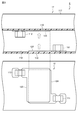
- FIG. 2 is a longitudinal sectional view (upper stage) of the sensing unit 11 constituting the deep body thermometer 1 and a diagram (lower stage) for explaining the arrangement of the temperature sensors 111 and 112.
- the deep thermometer 1 obtains the heat flow from the deep part of the user (subject) based on the temperature difference detected by the first temperature sensor 111 and the second temperature sensor 112 constituting the sensing unit 11. It is a non-heating type deep body thermometer which acquires deep body temperature. In particular, the deep thermometer 1 is stable and accurate regardless of the size (physical size) of the first temperature sensor 111 and the second temperature sensor 112 and even when the thermal resistor 113 is deformed. It is a deep thermometer that has a function of detecting deep body temperature well.
- the deep body thermometer 1 mainly includes a sensing unit 11 that is attached to the body surface and detects the temperature, and a temperature information processing unit 50 that acquires the deep body temperature based on the temperature detected by the sensing unit 11.
- the sensing unit 11 mainly includes a flexible substrate 110, a first temperature sensor 111, a second temperature sensor 112, and a thermal resistor 113.
- the temperature information processing unit 50 mainly includes an MCU 51 (deep body temperature acquisition unit 511), a wireless communication module 52, and a battery 53.
- the sensing unit 11 is attached to the user's body surface and detects the temperature of the user's body surface and the like. Therefore, the sensing unit 11 is mounted on a thermal resistor 113 having a predetermined thermal resistance value and a flexible substrate (film substrate) 110 having flexibility, for example, so that the thermal resistor 113 is sandwiched from the thickness direction.
- a pair of temperature sensors that is, a first temperature sensor 111 (corresponding to the first temperature detecting means described in claims) and a second temperature sensor 112 (corresponding to the second temperature detecting means). And is configured.
- the sensing unit 11 further includes a sheet-like heat insulating member 117 arranged so as to cover the thermal resistor 113 and the second temperature sensor 112.
- the thermal resistor 113 is formed into a rectangular thin sheet having a predetermined thickness, for example.
- the shape of the thermal resistor 113 is not limited to a rectangle, and may be, for example, a circle.
- the thermal resistor 113 is formed of a heat insulating material such as a polyethylene foam or a urethane foam.
- the thermal resistor 113 has flexibility so as to follow the shape and movement of the body surface.
- the thickness of the thermal resistor 113 is preferably about 0.1 mm to several mm, for example.
- the first temperature sensor 111 and the second temperature sensor 112 arranged so as to sandwich the thermal resistor 113 from the thickness direction are viewed from the thickness direction of the thermal resistor 113 (when viewed in plan). And the distance between the first temperature sensor 111 and the second temperature sensor 112 (the distance between the two temperature sensors) is larger than the thickness of the thermal resistor 113. Are also arranged to be larger.
- the first temperature sensor 111 and the second temperature sensor 112 arranged in the upper and lower layers are “a distance t between both sensors> a thickness T of the thermal resistor 113”. The position is shifted to the position.
- the thermal resistance of the path connecting the two sensors with a linear distance is increased.
- the thermal resistance is smaller than the thermal resistance in the thickness direction of the thermal resistor 113, and the heat flow passes through this path (between both sensors), thereby degrading the correlation between the thickness T of the thermal resistance 113 as a design parameter and the interlayer temperature difference. Resulting in.
- the thermal resistance of the thermal resistor 113 is defined by arranging the first temperature sensor 111 and the second temperature sensor 112 as described above, the first and second temperature sensors 111, 112
- the temperature difference between the first and second temperature sensors 111 and 112 in the temperature of each layer due to the physical size and the thickness T of the thermal resistor 113 can be accurately defined, and the value of the thermal resistance (thermal resistance and (Which is obtained from the product of the thickness T) is reduced.
- the first temperature sensor 111 and the second temperature sensor 112 for example, a thermistor or a resistance temperature detector whose resistance value changes with temperature is preferably used.
- the first temperature sensor 111 and the second temperature sensor 112 preferably have a heat capacity as small as possible from the viewpoint of improving responsiveness. Therefore, for example, a chip thermistor is preferably used as the first temperature sensor 111 and the second temperature sensor 112.
- Each of the first temperature sensor 111 and the second temperature sensor 112 is electrically connected to the temperature information processing unit 50 (MCU 51) via a printed wiring, and an electric signal (voltage value) corresponding to the temperature is received. It is read by the temperature information processing unit 50 (MCU 51).
- the temperature information processing unit 50 mainly includes an MCU (Micro Control Unit) 51, a wireless communication module 52, a battery 53, and the like.
- the first temperature sensor 111 and the second temperature sensor 112 are connected to the temperature information processing unit 50 (MCU 51), and are output from the first temperature sensor 111 and the second temperature sensor 112.
- the detected signal (temperature information) is input to the temperature information processing unit 50 (MCU 51).
- the temperature information processing unit 50 calculates the deep body temperature based on the temperature information detected by the first temperature sensor 111 and the second temperature sensor 112. Therefore, the temperature information processing unit 50 functionally includes a deep body temperature acquisition unit 511.
- the function of the deep body temperature acquisition unit 511 is realized by the MCU 51 executing a program stored in the ROM or the like.
- the deep body temperature acquisition unit 511 obtains the deep body temperature based on the thermal resistance value of the thermal resistor 113, the detected temperature of the first temperature sensor 111, and the detected temperature of the second temperature sensor 112 stored in advance. That is, the deep body temperature acquisition unit 511 functions as the deep body temperature acquisition unit described in the claims.
- the deep body temperature of the human body is Tcore
- the temperature detected by the first temperature sensor 111 is T1
- the temperature detected by the second temperature sensor 112 is T2.
- the core thermal resistance is Rcore
- the equivalent thermal resistance in the thickness direction of the thermal resistor 113 is R1
- the thermal resistance Rcore of the human body is known, or by setting, for example, a general (standard) thermal resistance value as the thermal resistance Rcore of the human body, the temperature T1 detected by the first temperature sensor 111, Further, the deep body temperature Tcore can be obtained from the temperature T2 detected by the second temperature sensor 112. The deep body temperature Tcore acquired by the deep body temperature acquisition unit 511 is output to the wireless communication module 52.
- the wireless communication module 52 transmits the acquired deep body temperature information to an external information terminal (for example, a smartphone).
- the wireless communication module 52 transmits the deep body temperature to an external information terminal via an AC electromagnetic field such as 13.56 MHz or wireless such as BT (Bluetooth (registered trademark)).
- the temperature information processing unit 50 contains a thin battery 53 therein.
- the battery 53 supplies power to the MCU 51, the wireless communication module 52, and the like.
- the sensing unit 11 constituting the deep thermometer 1 an arrangement method of the first temperature sensor 111 and the second temperature sensor 112 in the sensing unit 11
- the sensing unit 11 is manufactured, first, the first temperature sensor 111, the second temperature sensor 112, and the like are mounted on the flexible substrate 110 having flexibility. Next, the flexible substrate 110 on which the first temperature sensor 111, the second temperature sensor 112, and the like are mounted is bent so as to sandwich the sheet-like thermal resistor 113.
- the first temperature sensor 111 and the second temperature sensor 112 are arranged so as not to overlap each other when viewed from the thickness direction of the thermal resistor 113 (when viewed in plan), and The distance t between the first temperature sensor 111 and the second temperature sensor 112 is arranged to be larger than the thickness T of the thermal resistor 113. In this way, the sensing unit 11 is manufactured.
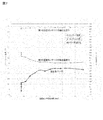
- FIG. 7 is a graph showing the detected temperatures T1, T2 of the temperature sensors 111, 112 and the difference between the detected temperatures (T1-T2) when the distance t between the temperature sensors is changed.
- the horizontal axis in FIG. 7 is the distance t (mm) between the temperature sensors, and the vertical axis is the detected temperature (° C.) and the temperature difference (° C.).
- the detected temperatures T1 and T2 of the temperature sensors 111 and 112 are stabilized, and both It was confirmed that the temperature difference (T1 ⁇ T2) of the detected temperature was the largest. It was also confirmed that the temperature difference (T1 ⁇ T2) did not increase further when the distance t between the temperature sensors was increased further.
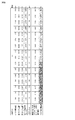
- FIG. 8 is a table showing the estimated depth body temperature deviation with respect to the mounting position variation of the temperature sensors 111 and 112 when the distance t between the temperature sensors is changed.
- the estimated depth body temperature deviation is within 0.2 ° C. within the range of 1.5t> T. That is, when the condition of 1.5t> T is satisfied, it is confirmed that even if the mounting positions of the temperature sensors 111 and 112 are shifted by 0.2 mm, the variation in measured values can be suppressed within ⁇ 0.2 ° C. It was. Therefore, it was confirmed that the deep body temperature can be stably measured (estimated) by satisfying t> 0.67 ⁇ T by design.
- the first temperature sensor 111 and the second temperature sensor 112 are viewed from the thickness direction of the thermal resistor 113 (when viewed in plan). ) Are arranged so as not to overlap each other, and are arranged such that the distance between the first temperature sensor 111 and the second temperature sensor 112 is larger than the thickness of the thermal resistor 113. Therefore, the path through which the heat flow flows can be made constant regardless of the size (physical size) of both the temperature sensors 111 and 112. In addition, even if the thermal resistor 113 is deformed (for example, even if the thermal resistor 113 is bent or crushed), it is possible to prevent the heat flow from flowing directly between the temperature sensors 111 and 112.
- a heat flow can be made to flow stably in the thickness direction of the thermal resistor 113, and it is possible to suppress variation in the measured value of the deep body temperature.
- the deep body temperature can be stably and accurately controlled. It becomes possible to detect.
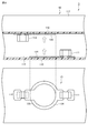
- FIG. 3 is a longitudinal sectional view (upper stage) of the sensing unit 12 constituting the deep thermometer 2 and a diagram (lower stage) for explaining the arrangement of the temperature sensors 111 and 112 and the wiring patterns 124 and 125.
- the same or equivalent components as those in the first embodiment are denoted by the same reference numerals.
- the sensing unit 12 further includes a first wiring pattern 124 connected to the first temperature sensor 111 and a second wiring pattern 125 connected to the second temperature sensor 112. Therefore, it is different from the deep thermometer 1 according to the first embodiment described above.
- the other structure is the same as that of the deep body thermometer 1 mentioned above, it abbreviate
- the ground pattern (or power supply pattern) formed on the flexible substrate 110 can be preferably used for each of the first wiring pattern 124 and the second wiring pattern 125.
- the first wiring pattern 124 and the second wiring pattern 125 are mutually (at least partially) when viewed from the thickness direction of the thermal resistor 113 (when viewed in plan). They are arranged so as to overlap.
- the first wiring pattern 124 and the second wiring pattern 125 are formed of a conductive material having a low thermal resistance, such as a thin film of copper or aluminum.
- each of the first wiring pattern 124 and the second wiring pattern 125 is rectangular, but the shape is not limited to a rectangle.
- the first wiring pattern 124 and the second wiring pattern 125 are arranged so as to overlap each other when viewed from the thickness direction of the thermal resistor 113.
- the thickness is mainly between the first wiring pattern 124 and the second wiring pattern 125 arranged so as to overlap each other (the thickness of the thermal resistor 113).
- the heat flow will flow stably (heat will be conducted stably).
- the influence by disturbance for example, external temperature etc.
- the deep body temperature can be detected more stably and accurately regardless of the size (physical size) of the first temperature sensor 111 and the second temperature sensor 112 and even when the thermal resistor 113 is deformed. It becomes possible to do.
- FIG. 4 is a longitudinal sectional view (upper stage) of the sensing unit 13 constituting the deep thermometer 3 and a diagram (lower stage) for explaining the arrangement of the temperature sensors 111 and 112 and the wiring patterns 134 and 135.
- the same or equivalent components as those in the second embodiment are denoted by the same reference numerals.
- the deep thermometer 3 is formed so that the first wiring pattern 134 and the second wiring pattern 135 constituting the sensing unit 13 have different areas (in the example of FIG. 4, the area of the first wiring pattern 134). > Area of the second wiring pattern 135), when viewed from the thickness direction of the thermal resistor 113 (when viewed in plan), one wiring pattern (the second wiring pattern 135 in the example of FIG. 4) is the other.
- This is different from the above-described deep thermometer 2 according to the second embodiment in that it is arranged so as to fit inside the wiring pattern (the first wiring pattern 134 in the example of FIG. 4).
- the magnitude relationship between the first wiring pattern 134 and the second wiring pattern 135 may be reversed.
- each of the first wiring pattern 134 and the second wiring pattern 135 has a circular shape, but the shape is not limited to a circular shape.
- the other configuration is the same as or similar to that of the above-described deep thermometer 2, and detailed description thereof is omitted here.
- the first wiring pattern 134 and the second wiring pattern 135 are formed so as to have different areas, and when viewed from the thickness direction of the thermal resistor 113 (in plan view) In the case), the second wiring pattern 135 is arranged so as to fit inside the first wiring pattern 134. For this reason, for example, even when a positional deviation (a variation in mounting position, a variation in assembly, or the like) occurs between the first wiring pattern 134 and the second wiring pattern 135 during manufacturing or the like, both the wiring patterns 134, It can suppress that the area of the area
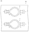
- FIG. 5 is a diagram for explaining the arrangement of the temperature sensors 111 and 112 and the wiring patterns 134 and 135 in the two sets of sensing units 13 and 13 constituting the deep thermometer 3A.
- the same or equivalent components as those in the third embodiment are denoted by the same reference numerals.
- the deep thermometer 3A includes a thermal resistor 113, a first temperature sensor 111, a second temperature sensor 112, a first wiring pattern 134, and a second wiring pattern 135. It differs from the depth thermometer 3 according to the third embodiment described above in that it includes two sets of the same as the sensing section 13 constituting the depth thermometer 3 according to the third embodiment. In addition, the thermal resistance value of the thermal resistor 113 which comprises each sensing part 13 and 13 is set identically.
- the temperature information processing unit 50 calculates the thermal resistance value of the thermal resistor 113 and the detected temperatures of the first temperature sensors 111 and 111 that constitute the sensing units 13 and 13, respectively. Based on the average value and the average value of the detected temperatures of the second temperature sensors 112 and 112, the deep body temperature is obtained.
- the other structure is the same as that of the deep thermometer 3 mentioned above, or is the same, detailed description is abbreviate
- the two sensing units 13 using the thermal resistors 113 having the same thermal resistance value are provided, for example, even if local temperature variation (non-uniformity) occurs, By averaging the detected temperatures of both the sensing units 13 and 13 (the first temperature sensors 111 and 111 and the second temperature sensors 112 and 112), a stable deep temperature can be obtained.
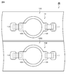
- FIG. 6 is a diagram for explaining the arrangement of the temperature sensors 111 and 112 and the wiring patterns 134 and 135 in the two sets of sensing units (the sensing unit 13 and the sensing unit 13B) constituting the deep thermometer 3B.
- the same or similar components as those in the first modification of the third embodiment are denoted by the same reference numerals.
- the deep thermometer 3B is different from the deep thermometer 3A according to the first modified example of the third embodiment described above in that it includes a sensing unit 13 and a sensing unit 13B instead of the two sets of sensing units 13.
- the thermal resistance value of the thermal resistor 13B3 configuring the sensing unit 13B is set to be different from the thermal resistance value of the thermal resistor 113 configuring the sensing unit 13.
- the thermal resistance value of the thermal resistor 13B3 can be adjusted, for example, by changing the thickness of the thermal resistor.
- the temperature information processing unit 50 (the deep body temperature acquisition unit 511) includes a thermal resistance value of the thermal resistor 113 that constitutes the sensing unit 13A, a detected temperature of the first temperature sensor 111, and a second temperature sensor.
- the deep body temperature is obtained based on the detected temperature 112, the thermal resistance value of the thermal resistor 13B3 constituting the sensing unit 13B, the detected temperature of the first temperature sensor 111, and the detected temperature of the second temperature sensor 112.
- the other structure is the same as that of the deep thermometer 3A mentioned above, or is the same, detailed description is abbreviate
- the two sensing units 13 and 13B using the thermal resistors 113 and 13B3 having different thermal resistance values are provided, that is, two heat flow systems having different thermal resistance values are formed. Therefore, the term of the thermal resistance Rcore of the human body can be canceled, and the deep body temperature can be obtained even if the thermal resistance Rcore of the human body is unknown. Therefore, since the deep body temperature can be acquired without assuming the thermal resistance Rcore of the human body, the deep body temperature can be acquired more accurately even when the thermal resistance Rcore of each user (subject) is different. .
- a known method can be used for canceling the thermal resistance Rcore of the human body.
- the present invention is not limited to the above-described embodiments, and various modifications can be made.
- the size, arrangement, etc. are not limited to the above embodiment, and can be arbitrarily set according to requirements such as accuracy.
- the configuration of the temperature information processing unit 50 is not limited to the above-described embodiment.
- the temperature information processing unit 50 may include a display unit and display the acquired deep body temperature.
- the depth thermometer 1 according to the first embodiment or the second embodiment. It can also be applied to the deep thermometer 2.
Landscapes
- Physics & Mathematics (AREA)
- General Physics & Mathematics (AREA)
- Nonlinear Science (AREA)
- Measuring And Recording Apparatus For Diagnosis (AREA)
- Measuring Temperature Or Quantity Of Heat (AREA)
Abstract
Description
まず、図1、図2を併せて用いて、第1実施形態に係る非加熱型の深部体温計1の構成について説明する。図1は、深部体温計1の機能構成を示すブロック図である。図2は、深部体温計1を構成するセンシング部11の縦断面図(上段)、及び各温度センサ111,112の配置を説明するための図(下段)である。
[数1]
Tcore=T2+{R1/(Rcore+R1)}(T1-T2) ・・・(1)
外気温Ta:20℃
断熱部材117(上部断熱材):縦25×横25×厚み1.4(mm)のウレタン材
第2の温度センサ112:縦1.0×横0.5×高さ0.5(mm)のチップサーミスタ
熱抵抗体113(下部断熱材):縦25×横25×厚み1.4(mm)のウレタン材
第1の温度センサ111:縦1.0×横0.5×高さ0.5(mm)のチップサーミスタ
生体表面温度Tb_surface:35℃
次に、図3を用いて、第2実施形態に係る深部体温計2について説明する。ここでは、上述した第1実施形態と同一・同様な構成については説明を簡略化又は省略し、異なる点を主に説明する。図3は、深部体温計2を構成するセンシング部12の縦断面図(上段)、及び、各温度センサ111,112並びに配線パターン124,125の配置を説明するための図(下段)である。なお、図3において第1実施形態と同一又は同等の構成要素については同一の符号が付されている。
次に、図4を用いて、第3実施形態に係る深部体温計3について説明する。ここでは、上述した第2実施形態と同一・同様な構成については説明を簡略化又は省略し、異なる点を主に説明する。図4は、深部体温計3を構成するセンシング部13の縦断面図(上段)、及び、各温度センサ111,112並びに配線パターン134,135の配置を説明するための図(下段)である。なお、図4において第2実施形態と同一又は同等の構成要素については同一の符号が付されている。
次に、図5を用いて、第3実施形態の第1変形例に係る深部体温計3Aについて説明する。ここでは、上述した第3実施形態と同一・同様な構成については説明を簡略化又は省略し、異なる点を主に説明する。図5は、深部体温計3Aを構成する2組のセンシング部13,13における各温度センサ111,112及び配線パターン134,135の配置を説明するための図である。なお、図5において第3実施形態と同一又は同等の構成要素については同一の符号が付されている。
次に、図6を用いて、第3実施形態の第2変形例に係る深部体温計3Bについて説明する。ここでは、上述した第3実施形態の第1変形例と同一・同様な構成については説明を簡略化又は省略し、異なる点を主に説明する。図6は、深部体温計3Bを構成する2組のセンシング部(センシング部13及びセンシング部13B)における各温度センサ111,112及び配線パターン134,135の配置を説明するための図である。なお、図6において第3実施形態の第1変形例と同一又は同等の構成要素については同一の符号が付されている。
11,12,13,13B センシング部
110 フレキシブル基板
111 第1の温度センサ
112 第2の温度センサ
113,13B3 熱抵抗体
117 断熱部材
124,134 第1の配線パターン
125,135 第2の配線パターン
50 温度情報処理ユニット
51 MCU
511 深部体温取得部
52 無線通信モジュール
53 バッテリ
Claims (6)
- 所定の熱抵抗値を有する熱抵抗体と、
前記熱抵抗体を、該熱抵抗体の厚さ方向から挟むように配置された第1の温度検出手段及び第2の温度検出手段と、
前記熱抵抗体の熱抵抗値、前記第1の温度検出手段の検出温度、及び前記第2の温度検出手段の検出温度に基づいて、深部体温を取得する深部体温取得手段と、を備え、
前記第1の温度検出手段と前記第2の温度検出手段とは、前記熱抵抗体の厚み方向から見た場合に互いに重ならないように配置されており、かつ、前記第1の温度検出手段と前記第2の温度検出手段との間の距離が、前記熱抵抗体の厚みよりも大きくなるように配置されていることを特徴とする深部体温計。 - 前記第1の温度検出手段と接続された第1の配線パターンと、
前記第2の温度検出手段と接続された第2の配線パターンと、をさらに備え、
前記第1の配線パターンと前記第2の配線パターンとは、前記熱抵抗体の厚み方向から見た場合に、少なくとも一部が互いに重なるように配置されていることを特徴とする請求項1に記載の深部体温計。 - 前記第1の配線パターン及び前記第2の配線パターンそれぞれは、基板に形成されたグランドパターン又は電源パターンであることを特徴とする請求項2に記載の深部体温計。
- 前記第1の配線パターンと前記第2の配線パターンとは、面積が異なるように形成されており、前記熱抵抗体の厚み方向から見た場合に、一方の配線パターンが他方の配線パターンの内側に収まるように配置されていることを特徴とする請求項2又は3に記載の深部体温計。
- 少なくとも前記熱抵抗体、前記第1の温度検出手段、及び前記第2の温度検出手段を有して構成されるセンシング部を2組備え、
それぞれの前記センシング部を構成する熱抵抗体は熱抵抗値が同一であり、
前記深部体温取得手段は、前記熱抵抗体の熱抵抗値、それぞれの前記センシング部を構成する第1の温度検出手段の検出温度の平均値、及び第2の温度検出手段の検出温度の平均値に基づいて、深部体温を取得することを特徴とする請求項1~4のいずれか1項に記載の深部体温計。 - 少なくとも前記熱抵抗体、前記第1の温度検出手段、及び前記第2の温度検出手段を有して構成されるセンシング部を2組備え、
それぞれの前記センシング部を構成する熱抵抗体は熱抵抗値が互いに異なり、
前記深部体温取得手段は、それぞれの前記センシング部を構成する熱抵抗体の熱抵抗値、それぞれの前記センシング部を構成する第1の温度検出手段の検出温度、及び第2の温度検出手段の検出温度に基づいて、深部体温を取得することを特徴とする請求項1~4のいずれか1項に記載の深部体温計。
Priority Applications (3)
| Application Number | Priority Date | Filing Date | Title |
|---|---|---|---|
| JP2018513223A JP6468398B2 (ja) | 2016-04-22 | 2017-04-21 | 深部体温計 |
| EP17786046.7A EP3431946B1 (en) | 2016-04-22 | 2017-04-21 | Deep body thermometer |
| US16/162,445 US10830649B2 (en) | 2016-04-22 | 2018-10-17 | Deep body thermometer |
Applications Claiming Priority (2)
| Application Number | Priority Date | Filing Date | Title |
|---|---|---|---|
| JP2016-085846 | 2016-04-22 | ||
| JP2016085846 | 2016-04-22 |
Related Child Applications (1)
| Application Number | Title | Priority Date | Filing Date |
|---|---|---|---|
| US16/162,445 Continuation US10830649B2 (en) | 2016-04-22 | 2018-10-17 | Deep body thermometer |
Publications (1)
| Publication Number | Publication Date |
|---|---|
| WO2017183709A1 true WO2017183709A1 (ja) | 2017-10-26 |
Family
ID=60116151
Family Applications (1)
| Application Number | Title | Priority Date | Filing Date |
|---|---|---|---|
| PCT/JP2017/015986 Ceased WO2017183709A1 (ja) | 2016-04-22 | 2017-04-21 | 深部体温計 |
Country Status (4)
| Country | Link |
|---|---|
| US (1) | US10830649B2 (ja) |
| EP (1) | EP3431946B1 (ja) |
| JP (1) | JP6468398B2 (ja) |
| WO (1) | WO2017183709A1 (ja) |
Cited By (2)
| Publication number | Priority date | Publication date | Assignee | Title |
|---|---|---|---|---|
| WO2019225532A1 (ja) * | 2018-05-21 | 2019-11-28 | 株式会社村田製作所 | 貼付型深部体温計 |
| US20210199514A1 (en) * | 2018-11-13 | 2021-07-01 | Murata Manufacturing Co., Ltd. | Sticking-type core body thermometer |
Families Citing this family (7)
| Publication number | Priority date | Publication date | Assignee | Title |
|---|---|---|---|---|
| JP6755034B1 (ja) | 2019-03-14 | 2020-09-16 | Biodata Bank株式会社 | 温度センサユニット及び体内温度計 |
| US20230366749A1 (en) * | 2020-09-04 | 2023-11-16 | Epymetrics Ag | Devices, systems and methods for determining a core temperature estimate |
| CN112386233A (zh) * | 2020-11-16 | 2021-02-23 | 成都凡米科技有限公司 | 一种基于ntc的深层皮下贴片测温系统、方法和设备 |
| CN113566975B (zh) * | 2021-08-05 | 2022-10-11 | 嘉兴温芯智能科技有限公司 | 基于热冲激法的深部温度测量方法、装置和耳机 |
| KR20230032212A (ko) | 2021-08-30 | 2023-03-07 | 삼성전자주식회사 | 체온 추정 장치 및 방법 |
| CN115900987A (zh) * | 2021-09-24 | 2023-04-04 | 苹果公司 | 用于使用与柔性电路集成的热电堆来进行温度感测的系统和方法 |
| US12474223B2 (en) | 2021-09-24 | 2025-11-18 | Apple Inc. | Temperature sensing systems and methods including multiple temperature sensors |
Citations (6)
| Publication number | Priority date | Publication date | Assignee | Title |
|---|---|---|---|---|
| JP2007315917A (ja) * | 2006-05-25 | 2007-12-06 | Terumo Corp | 深部温度測定装置及び外部通信装置 |
| JP2010513911A (ja) * | 2006-12-20 | 2010-04-30 | コーニンクレッカ フィリップス エレクトロニクス エヌ ヴィ | 核心温度を測定するための装置及び方法 |
| US20100121217A1 (en) * | 2006-12-06 | 2010-05-13 | Koninklijke Philips Electronics N. V. | Device for measuring core temperature |
| JP2012237670A (ja) * | 2011-05-12 | 2012-12-06 | Wakayama Univ | 体温計及びこれを備えた血圧計 |
| JP2013061232A (ja) * | 2011-09-13 | 2013-04-04 | Seiko Epson Corp | 温度測定システム及び温度算出方法 |
| JP2013200152A (ja) * | 2012-03-23 | 2013-10-03 | Terumo Corp | 体温計 |
Family Cites Families (15)
| Publication number | Priority date | Publication date | Assignee | Title |
|---|---|---|---|---|
| JPH02283354A (ja) | 1989-04-25 | 1990-11-20 | Terumo Corp | 信号送信機およびこれを有する心拍数計 |
| JP3579819B2 (ja) | 1997-12-26 | 2004-10-20 | 日本光電工業株式会社 | 生体信号送信装置 |
| JP2006136405A (ja) | 2004-11-10 | 2006-06-01 | Harada Denshi Kogyo Kk | 装着型無線伝送式心電計 |
| JP2009222543A (ja) | 2008-03-17 | 2009-10-01 | Citizen Holdings Co Ltd | 体温計 |
| GB0815694D0 (en) * | 2008-08-28 | 2008-10-08 | Cambridge Tempreature Concepts | Tempreature sensor structure |
| US8118485B2 (en) * | 2008-09-04 | 2012-02-21 | AGlobal Tech, LLC | Very high speed thin film RTD sandwich |
| CN102326060B (zh) | 2009-01-19 | 2015-02-25 | 皇家飞利浦电子股份有限公司 | 零热通量传感器及使用方法 |
| CN102458232A (zh) * | 2009-04-15 | 2012-05-16 | 亚利桑特保健公司 | 深部组织温度探测器结构 |
| US9068895B2 (en) * | 2009-04-15 | 2015-06-30 | 3M Innovative Properties Company | Deep tissue temperature probe constructions |
| JP5648283B2 (ja) * | 2009-12-24 | 2015-01-07 | セイコーエプソン株式会社 | 電子体温計及び体温測定方法 |
| JP2012132818A (ja) | 2010-12-22 | 2012-07-12 | Citizen Holdings Co Ltd | 温度測定装置 |
| JP6337416B2 (ja) | 2013-03-12 | 2018-06-06 | セイコーエプソン株式会社 | 温度測定装置 |
| JP2016057199A (ja) * | 2014-09-10 | 2016-04-21 | セイコーエプソン株式会社 | 温度測定装置及び温度測定方法 |
| EP3457922A1 (en) * | 2016-05-18 | 2019-03-27 | Koninklijke Philips N.V. | Single heat flux sensor arrangement |
| JP6711456B2 (ja) * | 2017-04-27 | 2020-06-17 | 株式会社村田製作所 | 体温計測装置 |
-
2017
- 2017-04-21 WO PCT/JP2017/015986 patent/WO2017183709A1/ja not_active Ceased
- 2017-04-21 JP JP2018513223A patent/JP6468398B2/ja active Active
- 2017-04-21 EP EP17786046.7A patent/EP3431946B1/en active Active
-
2018
- 2018-10-17 US US16/162,445 patent/US10830649B2/en active Active
Patent Citations (6)
| Publication number | Priority date | Publication date | Assignee | Title |
|---|---|---|---|---|
| JP2007315917A (ja) * | 2006-05-25 | 2007-12-06 | Terumo Corp | 深部温度測定装置及び外部通信装置 |
| US20100121217A1 (en) * | 2006-12-06 | 2010-05-13 | Koninklijke Philips Electronics N. V. | Device for measuring core temperature |
| JP2010513911A (ja) * | 2006-12-20 | 2010-04-30 | コーニンクレッカ フィリップス エレクトロニクス エヌ ヴィ | 核心温度を測定するための装置及び方法 |
| JP2012237670A (ja) * | 2011-05-12 | 2012-12-06 | Wakayama Univ | 体温計及びこれを備えた血圧計 |
| JP2013061232A (ja) * | 2011-09-13 | 2013-04-04 | Seiko Epson Corp | 温度測定システム及び温度算出方法 |
| JP2013200152A (ja) * | 2012-03-23 | 2013-10-03 | Terumo Corp | 体温計 |
Cited By (5)
| Publication number | Priority date | Publication date | Assignee | Title |
|---|---|---|---|---|
| WO2019225532A1 (ja) * | 2018-05-21 | 2019-11-28 | 株式会社村田製作所 | 貼付型深部体温計 |
| JPWO2019225532A1 (ja) * | 2018-05-21 | 2021-05-27 | 株式会社村田製作所 | 貼付型深部体温計 |
| US11927490B2 (en) | 2018-05-21 | 2024-03-12 | Murata Manufacturing Co., Ltd. | Sticking-type deep body thermometer |
| US20210199514A1 (en) * | 2018-11-13 | 2021-07-01 | Murata Manufacturing Co., Ltd. | Sticking-type core body thermometer |
| US12158378B2 (en) * | 2018-11-13 | 2024-12-03 | Murata Manufacturing Co., Ltd. | Sticking-type core body thermometer |
Also Published As
| Publication number | Publication date |
|---|---|
| US10830649B2 (en) | 2020-11-10 |
| EP3431946A1 (en) | 2019-01-23 |
| JPWO2017183709A1 (ja) | 2019-01-24 |
| JP6468398B2 (ja) | 2019-02-13 |
| EP3431946A4 (en) | 2019-11-20 |
| EP3431946B1 (en) | 2021-03-31 |
| US20190049317A1 (en) | 2019-02-14 |
Similar Documents
| Publication | Publication Date | Title |
|---|---|---|
| JP6468398B2 (ja) | 深部体温計 | |
| US12016658B2 (en) | Core body thermometer | |
| US11717170B2 (en) | Body core temperature sensor with two TEGs | |
| US10551252B2 (en) | Internal temperature measuring apparatus and sensor package | |
| EP2290357B1 (en) | Thermal humidity sensor | |
| JP6225766B2 (ja) | 内部温度測定方法及び内部温度測定装置 | |
| EP3699570A1 (en) | Core body temperature sensor and method for the manufacturing thereof | |
| JP6081983B2 (ja) | 体温計及び体温測定システム | |
| JP6350212B2 (ja) | 内部温度測定装置 | |
| CN113286991B (zh) | 温度传感器单元及体内温度计 | |
| US20140360267A1 (en) | Thermal convection type linear accelerometer | |
| US11828661B2 (en) | Core body thermometer | |
| CN116268635B (zh) | 一种具有感温的磁加热结构及气溶胶发生装置 | |
| JP2016170045A (ja) | 内部温度測定装置及び熱抵抗測定装置 | |
| EP3023804B1 (en) | Magnetic induction measuring device and method | |
| JP5628236B2 (ja) | 熱式湿度センサ | |
| JP7032432B2 (ja) | 熱伝達率測定素子 | |
| JP2025014789A (ja) | 温度測定装置 | |
| CN112082666A (zh) | 热电偶冷端补偿电路、热电偶组件及温度传感器 |
Legal Events
| Date | Code | Title | Description |
|---|---|---|---|
| ENP | Entry into the national phase |
Ref document number: 2018513223 Country of ref document: JP Kind code of ref document: A |
|
| WWE | Wipo information: entry into national phase |
Ref document number: 2017786046 Country of ref document: EP |
|
| NENP | Non-entry into the national phase |
Ref country code: DE |
|
| ENP | Entry into the national phase |
Ref document number: 2017786046 Country of ref document: EP Effective date: 20181019 |
|
| 121 | Ep: the epo has been informed by wipo that ep was designated in this application |
Ref document number: 17786046 Country of ref document: EP Kind code of ref document: A1 |