WO2017186149A1 - 智能履带式移动设备 - Google Patents
智能履带式移动设备 Download PDFInfo
- Publication number
- WO2017186149A1 WO2017186149A1 PCT/CN2017/082276 CN2017082276W WO2017186149A1 WO 2017186149 A1 WO2017186149 A1 WO 2017186149A1 CN 2017082276 W CN2017082276 W CN 2017082276W WO 2017186149 A1 WO2017186149 A1 WO 2017186149A1
- Authority
- WO
- WIPO (PCT)
- Prior art keywords
- base
- crawler
- mobile device
- guide wheel
- type mobile
- Prior art date
- Legal status (The legal status is an assumption and is not a legal conclusion. Google has not performed a legal analysis and makes no representation as to the accuracy of the status listed.)
- Ceased
Links
Images




Classifications
-
- B—PERFORMING OPERATIONS; TRANSPORTING
- B62—LAND VEHICLES FOR TRAVELLING OTHERWISE THAN ON RAILS
- B62D—MOTOR VEHICLES; TRAILERS
- B62D55/00—Endless track vehicles
- B62D55/08—Endless track units; Parts thereof
- B62D55/10—Bogies; Frames
-
- B—PERFORMING OPERATIONS; TRANSPORTING
- B62—LAND VEHICLES FOR TRAVELLING OTHERWISE THAN ON RAILS
- B62D—MOTOR VEHICLES; TRAILERS
- B62D55/00—Endless track vehicles
- B62D55/06—Endless track vehicles with tracks without ground wheels
- B62D55/065—Multi-track vehicles, i.e. more than two tracks
-
- A—HUMAN NECESSITIES
- A01—AGRICULTURE; FORESTRY; ANIMAL HUSBANDRY; HUNTING; TRAPPING; FISHING
- A01D—HARVESTING; MOWING
- A01D34/00—Mowers; Mowing apparatus of harvesters
- A01D34/835—Mowers; Mowing apparatus of harvesters specially adapted for particular purposes
-
- B—PERFORMING OPERATIONS; TRANSPORTING
- B62—LAND VEHICLES FOR TRAVELLING OTHERWISE THAN ON RAILS
- B62D—MOTOR VEHICLES; TRAILERS
- B62D55/00—Endless track vehicles
- B62D55/08—Endless track units; Parts thereof
- B62D55/18—Tracks
- B62D55/24—Tracks of continuously flexible type, e.g. rubber belts
- B62D55/242—The flexible band being semi-rigid for resisting back-flexing and contributing to spring the vehicle
-
- B—PERFORMING OPERATIONS; TRANSPORTING
- B62—LAND VEHICLES FOR TRAVELLING OTHERWISE THAN ON RAILS
- B62D—MOTOR VEHICLES; TRAILERS
- B62D55/00—Endless track vehicles
- B62D55/08—Endless track units; Parts thereof
- B62D55/18—Tracks
- B62D55/24—Tracks of continuously flexible type, e.g. rubber belts
- B62D55/244—Moulded in one piece, with either smooth surfaces or surfaces having projections, e.g. incorporating reinforcing elements
-
- B—PERFORMING OPERATIONS; TRANSPORTING
- B62—LAND VEHICLES FOR TRAVELLING OTHERWISE THAN ON RAILS
- B62D—MOTOR VEHICLES; TRAILERS
- B62D55/00—Endless track vehicles
- B62D55/08—Endless track units; Parts thereof
- B62D55/30—Track-tensioning means
Definitions
- the present invention relates to the field of intelligent mobile devices, and more particularly to smart tracked mobile devices.
- the lawn mower is a mechanical tool for trimming vegetation, which is composed of a cutter head, an engine, a running mechanism, an armrest, and the like.
- the cutter head is equipped with a blade, and the output shaft of the engine is connected with the blade on the cutter head.
- the blade is mowing under the high-speed rotation of the engine, and the work efficiency is high, which saves the working time of the weeding worker and reduces a large amount of human resources.
- crawler mowers can reduce grounding pressure, protect vegetation, and solve the problem of high grass cutting on slopes.
- the track, drive wheel and guide wheel of the existing crawler mower are visible. When the crawler mower is in operation, the user may be caught between the track and the drive wheel and the guide wheel due to misoperation. Sports squeeze. The same problem has arisen with other smart mobile devices that use track drives.
- An intelligent crawler type mobile device that automatically walks and works in a predetermined work area, including a base, a crawler mechanism, and a guard mechanism, the track mechanism including a guide wheel, a drive wheel, and a crawler, a guide wheel and the driving wheel are located on two sides of the base, the track is wound around the guiding wheel and the driving wheel, and the winding wheel of the guiding wheel/drive wheel and the track is defined as a danger zone.
- the guard mechanism is configured to prevent the track mechanism from injuring the user in the danger zone.
- the guard mechanism includes at least one sensor, the sensing area of the sensor covering at least the danger zone.
- the crawler mechanism moves, and the exposed crawler mechanism may cause mechanical damage to the operator.
- the sensor can send a sensing signal to the controller when the human body approaches the danger zone, and the controller immediately receives the signal.
- a stop command is issued to the traveling motor to ensure that the crawler mechanism stops when the human body reaches the danger zone, and the crawler mechanism is prevented from causing harm to the human body in the danger zone.
- the senor is at least one of an infrared sensor, an ultrasonic sensor, a capacitive sensor, and a laser sensor.
- the guard mechanism includes a first protective cover, and the first protective cover is disposed on a side of the track mechanism away from the base for shielding the danger zone.
- the crawler mechanism moves, and the exposed crawler mechanism may cause mechanical damage to the operator.
- the first guard mechanism is disposed on the side of the crawler mechanism away from the base to protect the operator and prevent the operator from being caught by the crawler mechanism. Extrusion allows the operator to safely use the smart tracked mobile device to avoid mechanical damage caused by misuse.
- the bottom of the base is provided with a cutting device that extends to both sides of the base, and the first protective cover is also used to shield the cutting device.
- the first protective cover is located between the guide wheel and the drive wheel and extends from the guide wheel to the drive wheel.
- the first protective cover is an elongated plate having curved ends at both ends, and the curved end of the first protective cover and the guide wheel and the The edge of the drive wheel fits.
- the first protective cover is a track protection cover
- the track protection cover is located at an outer edge of the drive wheel and the guide wheel, and is located at the drive wheel and the guide Between the rounds.
- one end of the track protection cover is an arcuate end, the curved end is engaged with the edge of the guide wheel or the drive wheel, and the track protection cover has four One is located outside each of the drive wheels and the guide wheels.
- the bottom of the base is provided with a cutting device that extends to both sides of the base, and the protective mechanism further includes a second protective cover for shielding the cutting device.
- the second protective cover is a cutting device protective cover
- the cutting device protective cover is disposed on a side of the base on which the cutting device protrudes, and is located at the driving wheel And the guide wheel to shield the cutting device on the base.
- the second protective cover is a hollow housing, and the cutting device is located in a receiving cavity formed by the housing.
- the smart crawler mobile device is a smart smart crawler mobile device, further comprising a controller, a cutting motor and a travel motor for controlling automatic walking and working of the smart crawler mobile device.
- a controller is disposed in the base and controls the cutting motor and the row The rotation of the motor is driven, and the crawler is driven by the travel motor to drive the smart crawler type mobile device to walk.
- the present invention also provides a crawler mechanism, comprising: a base; a drive wheel rotatably disposed on the base; a guide wheel supporting the base together with the drive wheel, movably disposed relative to the base; The drive wheel and the guide wheel are rotated once around the drive wheel and the guide wheel; and the tensioning mechanism includes an adjustment member coupled to the guide wheel to change the position of the guide wheel, and the adjustment member is located at the adjustment member An elastic member with the base, wherein the elastic member provides a driving force for moving the adjusting member, and the adjusting member drives the guide wheel to move and tension the crawler belt.
- the guide wheel is connected to the adjusting member, and when the crawler belt is loosened, the elastic member provides a driving force for moving the adjusting member, and the adjusting member drives the guide wheel to move and tension the crawler belt, so that the crawler belt can be automatically tensioned in real time. Prevent the track from coming off.
- the elastic member provides an elastic force for linearly or oscillating movement of the adjustment member relative to the base, and the adjustment member moves the guide wheel for linear motion or oscillating motion.
- the resilient member provides a pushing or pulling force to move the adjustment member.
- the wheel center distance between the guide wheel and the drive wheel increases.
- the bottoms of the drive wheel and the guide wheel are in the same horizontal plane.
- the guide wheel and the adjustment member are rotatably connected by a rotating shaft.
- the adjusting member has a guiding shaft that is slidably engaged with the base in a linear direction, the elastic member is disposed on the guiding shaft, and the two ends of the elastic member are respectively received by the adjusting member and the The pressure of the base.
- the adjusting component is rotatably coupled to the base, and the guiding wheel is rotatably coupled to the adjusting component, wherein an axis of rotation of the adjusting component on the base is adjusted with the guiding wheel
- the axis of rotation on the component is eccentric.
- the adjusting member includes a first fulcrum pivotally supported on the base, a second fulcrum pivotally supported on the guide wheel, and a connecting rod connecting the first fulcrum and the second fulcrum .
- the elastic member is a torsion spring disposed on the first fulcrum, and the two ends of the torsion spring respectively press the connecting rod and the base.
- the elastic member is coupled between the link and the base.
- the base is further provided with a motor that drives the rotation of the drive wheel.
- the track has an elastic expansion capability.
- the track is a series closed loop structure in which a plurality of rubber blocks are hinged by a metal pin.
- the side of the track that is in contact with the ground has a flexible material.
- FIG. 1 is a front elevational view of a smart crawler type mobile device according to an embodiment of the present invention
- FIG. 2 is a side view of the smart crawler type mobile device shown in FIG. 1;
- FIG. 3 is a side view of a smart crawler type mobile device according to another embodiment of the present invention.
- FIG. 4 is a partial schematic view of the smart crawler type mobile device shown in FIG. 3;
- FIG. 5 is a side view of a smart crawler type mobile device according to still another embodiment of the present invention.
- Figure 6 is a schematic cross-sectional view of the crawler mechanism of the first embodiment
- Figure 7 is a partial side elevational view of the crawler mechanism of the first embodiment
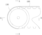
- Figure 8 is a cross-sectional view taken along line A-A of Figure 7;
- Figure 9 is a cross-sectional view taken along line B-B of Figure 7;
- Figure 10 is a partial side elevational view of the crawler mechanism of the second embodiment
- Figure 11 is a cross-sectional view taken along line C-C of Figure 10;
- Figure 12 is a partial side elevational view of the crawler mechanism of the third embodiment
- Figure 13 is a cross-sectional view taken along line D-D of Figure 12;
- the intelligent crawler type mobile device of the present invention automatically walks and works in a predetermined work area, such as a crawler mower, a crawler type snow sweeper, a crawler type leaf collecting device, and the like.
- a crawler type lawn mower is taken as an example.
- the crawler mower includes a base 110, a crawler mechanism 100 and a guard mechanism 400.
- the crawler mechanism 100 includes a guide wheel 130, a drive wheel 120 and a crawler belt 140.
- the guide wheel 130 and the drive wheel 120 are located on both sides of the base 110, and the crawler belt 140 is wound around Guide wheel 130 and drive wheel 120.
- the guard mechanism 400 includes a first protective cover 420 disposed on a side of the track mechanism 100 away from the base 110 and configured to shield the guide wheel 130 / the drive wheel 120 from the track 140
- the winding is defined as a danger zone 101.
- the crawler belt 140 cooperates with the guide wheel 130 and the driving wheel 120, and the exposed crawler belt 140, the guide wheel 130 and the driving wheel 120 may cause mechanical damage to the operator, and the first protective cover 420 is provided.
- the operator On the side of the crawler mechanism 100 away from the base 110, the operator is protected from the engagement of the crawler belt 140 with the guide wheel 130/drive wheel 120 to prevent mechanical damage caused by misoperation, so that the operator can safely use the crawler belt. Lawn mower.
- a cutting device (not shown) is disposed at the bottom of the base 110, and the cutting device extends to both sides of the base 110.
- the first protective cover 420 is also used to shield the cutting device on the base 110.
- the crawler mower drives the cutting device to work, and the exposed cutting device may cut the operator.
- a protective cover shields the cutting device and prevents the body parts such as hands and feet from reaching the cutting device to protect the operator. It is to be understood that the cutting device may be a cutter head or a straw rope or the like, which is not limited herein.
- the first protective cover 420 is located between the guide wheel 130 and the drive wheel 120 and extends from the guide wheel 130 to the drive wheel 120.
- the first cover plate 420 is fixed relative to the base 110.
- the first protective cover 420 directly seals the crawler belt 140 to prevent the human body part such as the hand from being wound into the guide wheel 130 or the cutting device in the driving wheel 120 or the base 110, and the structural design prevents the operator from misoperation. Bring mechanical damage.
- first protective cover 420 is an elongated plate with curved ends at both ends, and the two curved ends of the first protective cover 420 are respectively engaged with the edges of the guide wheel 130 and the driving force 24.
- the present embodiment differs from the first embodiment only in the protection mechanism 400.
- the protection mechanism 400 includes a first protective cover 440.
- the first protective cover 440 includes a track protection cover, and the track protection cover is located at an outer edge of the drive wheel 120 and the guide wheel 130, and Located between the guide wheel 130 and the drive wheel 26, the track protection cover is fixed relative to the base 110.
- the crawler cover is designed to prevent a human body portion such as a finger from being caught in the drive wheel 120 or the guide wheel 130, and is damaged by the crawler belt 140 and the drive wheel 120 or the crawler belt 140 and the guide wheel 130.
- one end of the track protection cover is an arc-shaped end, and the curved end is matched with the edge of the guide wheel 130/drive wheel 120.
- the track protection cover has four, respectively located on each of the guide wheel 130 and the drive wheel 120. Outside.
- a cutting device (not shown) is disposed at the bottom of the base 110, and the cutting device extends to both sides of the base 110.
- the shielding mechanism 400 further includes a second protective cover 460 for shielding the cutting device.
- the second protective cover 460 is a cutting device protective cover.
- the cutting device protective cover is disposed on a side of the base 110 on which the cutting device protrudes, and is located between the driving wheel 120 and the guiding wheel 130 to shield the base 110.
- the upper cutting device prevents the human body part such as the hand from reaching the position of the cutting device and causing injury.
- the second protective cover 460 is a hollow housing, and the cutting device on the base 110 is located in the receiving cavity formed by the housing.
- the second protective cover 460 is provided with a uniform strip-like slit, so that the vegetation to be repaired is in contact with the cutting device on the base 110.
- the crawler mower is a smart crawler mower, and the crawler mower further includes a controller (not shown) for controlling the automatic walking and working of the crawler mower, A cutting motor (not shown) and a traveling motor (not shown) are disposed in the base 110 and control the rotation of the cutting motor and the traveling motor.
- the crawler belt 140 is driven by the traveling motor to drive the crawler mower to travel. Under the control of the controller, the crawler mower automatically walks according to the preset route and automatically turns over when encountering obstacles.
- the controller controls the rotation speed of the cutting motor according to the actual mowing conditions encountered by the mowing mechanism to make the crawler
- the lawn mower is intelligent.
- the guard mechanism 400 includes at least one sensor 480, the sensing area of the sensor 480 covering at least the danger zone 101, and in some cases, the sensor 480 may also need to perform sensing of other portions. jobs.
- the sensor 480 is connected to the controller. When the sensor 480 senses that the human body (such as a hand or foot or other human body part) is approaching, the sensor sends a sensing signal to the controller, and the controller sends a stop to the traveling motor immediately after receiving the signal. The command ensures that the crawler mechanism 100 stops when the human body reaches the danger zone 101, preventing the crawler mechanism 100 from injuring the human body in the danger zone 101.
- the number of sensors 480 can be selected according to the number of track mechanisms and the size of the sensing area.
- a typical crawler mower includes two track mechanisms 100 (i.e., two drive wheels 120, two driven wheels, and two tracks 140) on either side of the distribution base 110. Therefore, two sensors 480 are preferred in this embodiment.
- the sensor may select at least one of an infrared sensor, an ultrasonic sensor, a capacitive sensor, and a laser sensor.
- the sensor in the present invention may also be other sensing elements that are not enumerated and capable of sensing the human body.
- the protective structure of the present invention is also applicable to other smart crawler type mobile devices, which not only protects the human body from being damaged by the crawler mechanism 100, but also prevents foreign matter from entering the crawler mechanism 100 and being caught in At the junction of the track with the drive wheel 120/guide wheel 130, the track 140 or drive wheel 120/guide wheel 130 is damaged.
- the protective cover directly prevents the foreign matter from entering the crawler mechanism 100; and the sensor 480 controls the crawler mechanism 100 to stop the movement by the controller when the foreign matter enters, which is convenient for directly taking out the foreign matter, and preventing the foreign matter from being caught in the crawler 140.
- the connection with the drive wheel 120 / guide wheel 130 The connection with the drive wheel 120 / guide wheel 130.
- the intelligent crawler type mobile device of the present invention also provides an improved crawler mechanism and provides two different embodiments.
- the first embodiment provides a crawler mechanism 100 that can be applied to various tools that require the use of a crawler mechanism.
- the tool is a lawn mower as an example.
- the crawler mechanism itself is suitable for the working environment in various working conditions, especially in the work with grooves and ramps.
- the crawler belt since the crawler belt has a large land area, the pressing force against the lawn can be reduced, and the abrasion of the lawn can be reduced.
- the track mechanism 100 includes a base 110, a drive wheel 120, a guide wheel 130, a track 140, and a tensioning mechanism.
- the tensioning mechanism is used to adjust the position of the guide wheel 130.
- the tensioning mechanism immediately changes the position of the guide wheel 130, so that the guide wheel 130 re-tensions the crawler belt 140 to prevent the crawler belt 140 from falling off.
- the base 110 is the frame of the entire crawler mechanism 100. When in the lawn mower, the base 110 can serve as the chassis for the entire lawn mower. Other components of the lawn mower, such as a mowing mechanism, may be located at the bottom of the base 110 to perform a mowing action; and a power mechanism such as a lawn mower may be placed over the base 110 and then covered to obtain a neat Beautiful lawn mower.
- a mowing mechanism such as a lawn mower may be placed over the base 110 and then covered to obtain a neat Beautiful lawn mower.
- the drive wheel 120 is rotatably supported by the base 110 and is driven to rotate by a motor 112 disposed on the base 110.
- the motor 112 of the present embodiment employs an electric motor, and may be replaced by other types of motors such as a pneumatic motor, a fuel motor, and the like.
- the base 110 itself may not be mounted with the motor 112, particularly when the base 110 is not used as a chassis for the tool.
- the guide wheel 130 is spaced apart from the drive wheel 120.
- the track 140 surrounds the drive wheel 120 and the guide wheel 130 for a revolution around the drive wheel 120 and the guide wheel 130.
- the driving wheel 120 can rotate the crawler belt 140 while driving the lawn mower to advance.
- the steering of the lawn mower is also achieved by the drive of the drive wheel 120 by the motor 112.
- the motor 112 is provided with a pair.
- the crawler belts 140 on both sides of the lawn mower are respectively provided with a drive wheel 120 and a guide wheel 130.
- Each of the drive wheels 120 independently corresponds to one motor 112.
- the two motors 112 output different rotational speeds, so that the crawler belts 140 on both sides of the mower realize differential motion, thereby achieving steering of the lawn mower.
- the guide wheel 130 is coupled to the tensioning mechanism to be movably disposed relative to the base 110. Moreover, the guide wheel 130 cooperates with the drive wheel 120 to support the base 110. In other words, the guide wheel 130 is used both as a support wheel for the base 110 and as a tensioning wheel for the tension track 140, which greatly simplifies the structure of the track mechanism 100.
- the bottoms of the driving wheel 120 and the guiding wheel 130 are disposed at the same horizontal plane.
- the radii of the drive wheel 120 and the guide wheel 130 are preferably set to be uniform, simplifying the design requirements, and of course the radii of the two may be inconsistent, designed as desired.
- the track 140 at the bottom of the two extends in a plane and has a larger footprint, i.e., the portion of the track 140 between the drive wheel 120 and the guide wheel 130 can be used to walk on the ground.
- the tensioning mechanism includes an adjustment member 152 coupled to the guide wheel 130 to change the position of the guide wheel 130, and an elastic member 154 between the adjustment member 152 and the base 110, wherein the elastic member 154 provides a driving force for moving the adjustment member 152, and the adjustment member The 152 drives the guide wheel 130 to move and tension the track 140.
- the elastic member 154 is configured to provide an elastic force for linearly moving the adjusting member 152 relative to the base 110.
- the adjusting member 152 moves, the guiding wheel 130 is linearly moved.
- the elastic member 154 drives the adjusting member 152 and drives the guide wheel 130 to move, the wheel center distance between the guide wheel 130 and the driving wheel 120 is increased, so that the crawler belt can be tensioned.
- the crawler belt 140 applies a pressure F1 to the guide wheel 130, and the direction is vertically upward.
- the elastic member 154 gives a vertical downward elastic force F2 to the adjusting member 152, so that the adjusting member 152 drives the guide wheel 130 away from the driving wheel 120.
- the adjusting member 152 has a guiding shaft 1522 that is slidably engaged with the base 110 in a linear direction.
- the elastic member 154 is disposed on the guiding shaft 1522, and the two ends of the elastic member are respectively received by the adjusting member 152 and the base 110. pressure.
- the elastic member 154 is in a pre-compressed state, so that the thrust of the adjustment member 152 to linearly move can be provided.
- the elastic member 154 may also be a pulling force that provides linear movement of the adjusting member 152, such as by changing the mounting position of the elastic member 154, so that the elastic member 154 is in a stretched state.
- the resilient member 154 is preferably spring loaded over the guide shaft 1522. It may also be another elastic body, such as a high-strength rubber that may be in the form of a cylinder.
- the guide wheel 130 moves along with the adjustment member 142. Referring to FIG. 8, a rotational connection is achieved between the guide wheel 130 and the adjustment member 152 via a rotating shaft 132.
- the motor 112 only needs to provide a relatively small driving force to the drive wheel 120.
- the guide wheel 130 may be internally provided with a bearing 134 that bears against the bearing 134.
- the crawler mechanism 100 is used.
- the side of the track 140 that is in contact with the ground has a flexible material, such as rubber, which can reduce the wear of the track 140 to the lawn when the lawn mower is walking.
- the crawler belt 140 is a series closed loop structure in which a plurality of rubber blocks are hinged by a metal pin. When the crawler belt 140 is rotated, the rubber block is mainly twisted, so that noise generated is small.
- Track 140 can also be a plastic track or a metal track.
- the crawler belt 140 is in rigid contact when it comes into contact with the ground.
- the crawler belt 140 is made of a flexible material such as rubber, and has an elastic expansion and contraction capability, thereby improving the ability to adapt to different road conditions, and is not easily broken.
- the elastic member 154 drives the adjustment member 152 to move linearly, thereby causing the guide wheel 130 to re-tension the crawler belt 140.
- the second embodiment provides a crawler mechanism 1000 which can be applied to various tools that require the use of a crawler mechanism.
- the track mechanism 1000 can be used in a lawn mower.
- the crawler mechanism 1000 includes a base 110, a drive wheel (omitted not shown), a guide wheel 230, a crawler belt 240, and a tensioning mechanism.
- the track mechanism 1000 can be used in a lawn mower and can be used as a chassis for the entire lawn mower.
- the driving wheel and the guiding wheel 230 are used together to support the base 210.
- the bottoms of the drive wheel and the guide wheel 230 are disposed to be at the same horizontal plane.
- the radii of the drive wheel and guide wheel 230 are then preferably set to be uniform. The following highlights the differences from the second embodiment.
- the tensioning mechanism includes an adjustment member 252 and an elastic member 254.
- the adjusting member 252 includes a first supporting shaft 2522 that is rotatably supported on the base 210, a second supporting shaft 2523 that is rotatably supported by the guiding wheel 230, and a connecting rod 2524 that connects the first supporting shaft 2522 and the second supporting shaft 2523.
- the first shaft 2522 and the second shaft 2523 are eccentrically disposed such that the axis of rotation of the adjustment member 252 on the base 110 and the axis of rotation of the guide wheel 230 on the adjustment member 252 are eccentric.
- the elastic member 254 is a torsion spring disposed on the first support shaft 2522, and the two ends of the torsion spring respectively press the connecting rod 2524 and base 210.
- the resilient member 254 can provide an elastic force that causes the adjustment member 252 to oscillate relative to the base 210.
- the guide wheel 230 is caused to swing, and the wheel center distance between the guide wheel 230 and the driving wheel is increased, so that the crawler belt 240 can be re-tensioned.
- a third embodiment provides a crawler mechanism 300 that can be applied to various tools that require the use of a crawler mechanism.
- the crawler mechanism 300 includes a base 310, a drive wheel (omitted not shown), a guide wheel 330, a crawler belt 340, and a tensioning mechanism.
- the track mechanism 300 can be used in a lawn mower and can be used as a chassis for the entire lawn mower.
- the driving wheel and the guiding wheel 330 are used together to support the base 310.
- the driving wheel and the bottom of the guiding wheel 330 are disposed at the same horizontal plane.
- the radii of the drive wheel and guide wheel 230 are then preferably set to be uniform. The following highlights the differences from the second embodiment.
- the tensioning mechanism includes an adjustment member 352 and an elastic member 354.
- the adjusting member 352 includes a first supporting shaft 3522 rotatably supported on the base 310, a second supporting shaft 3523 rotatably supported by the guiding wheel 330, and a connecting rod 3524 connecting the first supporting shaft 3522 and the second supporting shaft 3523.
- the first shaft 3522 and the second shaft 3523 are eccentrically disposed such that the axis of rotation of the adjustment member 352 on the base 310 and the axis of rotation of the guide wheel 330 on the adjustment member 350 are eccentric.
- the elastic member 254 is a tension spring that is coupled between the link 3524 and the base 310. Specifically, the elastic member 254 is disposed at one side of the link 3524 and away from the drive wheel (in FIG. 12, a drive wheel not shown is located on the right side of the guide wheel 330).
- the resilient member 254 When the track 340 is loosened, the resilient member 254 provides an elastic force that causes the adjustment member 252 to oscillate relative to the base 210, which is a pulling force.
- the axis of the oscillating motion of the adjustment member 252 is the first fulcrum 3522.
- the elastic force can also be a thrust.
- the position of the adjusting member 352 is as shown in the position A in the figure. Since the guide wheel 330 is not subjected to the pressure of the crawler belt 340, the elastic member 354 is not stretched, and the adjusting member 352 is Set to a certain angle to the left counterclockwise with respect to the vertical line. It is preferably set here to 8 degrees.
- the guide wheel 330 is subjected to the pressure of the track 340, the adjustment member 352 is swung clockwise and then moved to the B position and the elastic member 354 is stretched. At the B position, the link 3524 extends along the vertical line.
- the crawler belt 340 becomes loose, the pressure given to the guide wheel 330 will become smaller due to the elastic member 354.
- the front member is in a stretched state, so that the elastic member 354 can pull the adjusting member 352 to swing clockwise during the process of reducing the stretching length, and when the adjusting member 352 swings, the steering wheel 230 is driven to swing, and the guiding wheel 230 and the driving wheel are driven.
- the wheel center distance between them increases so that the track can be re-tensioned.
Landscapes
- Engineering & Computer Science (AREA)
- Chemical & Material Sciences (AREA)
- Combustion & Propulsion (AREA)
- Transportation (AREA)
- Mechanical Engineering (AREA)
- Life Sciences & Earth Sciences (AREA)
- Environmental Sciences (AREA)
- Harvester Elements (AREA)
Abstract
一种智能履带式移动设备,所述智能履带式移动设备在预定的工作区域内自动行走并工作,包括底座(110)、履带机构(100)和防护机构(400),所述履带机构(100)包括导向轮(130)、驱动轮(120)和履带(140),所述导向轮(130)及所述驱动轮(120)位于所述底座(110)两侧,所述履带(140)绕设于所述导向轮(130)和所述驱动轮(120)上,所述导向轮/驱动轮与履带的绕入绕出处定义为危险区,所述防护机构(400)配置为能够阻止履带机构在危险区对使用者造成伤害,防护机构(400)设于履带机构(100)远离底座(110)的一侧,保护操作人员,防止操作人员被履带与导向轮/驱动轮的啮合挤压,避免误操作产生机械伤害。
Description
本发明涉及智能移动设备领域,特别是涉及智能履带式移动设备。
割草机是一种用于修剪植被的机械工具,它是由刀盘、发动机、行走机构、扶手等组成。刀盘上装有刀片,发动机的输出轴与刀盘上的刀片连接,刀片在发动机的高速旋转的带动下割草,工作效率高,节省了除草工人的作业时间,减少了大量的人力资源。履带式割草机与一般的割草机相比可以减小接地压力、保护植被,并解决了斜坡上割草难度大的问题。但是,现有的履带式割草机的履带、驱动轮和导向轮均是可见的,履带式割草机在工作时,用户由于误操作,可能会被履带和驱动轮、导向轮之间的运动挤压。同样的问题也出现其他采用履带传动机构的智能移动设备上。
发明内容
基于此,有必要针对一般的智能履带式移动设备会产生机械伤害的问题,提供一种具有防护机构的智能履带式移动设备。
一种智能履带式移动设备,所述智能履带式移动设备在预定的工作区域内自动行走并工作,包括底座、履带机构和防护机构,所述履带机构包括导向轮、驱动轮和履带,所述导向轮及所述驱动轮位于所述底座两侧,所述履带绕设于所述导向轮和所述驱动轮上,所述导向轮/驱动轮与履带的绕入绕出处定义为危险区,所述防护机构配置为能够阻止履带机构在危险区对使用者造成伤害。
在其中一个实施例中,所述防护机构包括至少一个传感器,所述传感器的感测区域至少覆盖危险区。
上述智能履带式移动设备工作时,履带机构运动,外露的履带机构可能会对操作人员产生机械伤害,传感器可在人体靠近危险区时,发送感测信号给控制器,控制器接收到信号后立即对行走马达发出停转指令,确保在人体到达危险区时履带机构停转,避免履带机构在危险区内对人体造成伤害。
在其中一个实施例中,所述传感器为红外传感器、超声波传感器、电容传感器、激光传感器中的至少一种。
在其中一个实施例中,所述防护机构包括第一防护盖板,所述第一防护盖板设于所述履带机构远离所述底座的一侧,用于遮蔽所述危险区。
上述智能履带式移动设备工作时,履带机构运动,外露的履带机构可能会对操作人员产生机械伤害,第一防护机构设于履带机构远离底座的一侧,保护操作人员,防止操作人员被履带机构挤压,使操作人员可以安全的使用该智能履带式移动设备,避免误操作产生的机械伤害。
在其中一个实施例中,所述底座底部设有切割装置,所述切割装置伸向所述底座两侧,所述第一防护盖板还用于遮蔽所述切割装置。
在其中一个实施例中,所述第一防护盖板位于所述导向轮和所述驱动轮之间,并从所述导向轮延伸至所述驱动轮。
在其中一个实施例中,所述第一防护盖板为两端为弧形端部的长条板,且所述第一防护盖板的所述弧形端部与所述导向轮和所述驱动轮的边缘配合。
在其中一个实施例中,所述第一防护盖板为履带防护盖板,所述履带防护盖板位于所述驱动轮和所述导向轮的外侧边缘,且位于所述驱动轮和所述导向轮之间。
在其中一个实施例中,所述履带防护盖板的一端为弧形端部,所述弧形端部与所述导向轮或所述驱动轮的边缘配合,且所述履带防护盖板有四个,分别位于每个所述驱动轮和所述导向轮外侧。
在其中一个实施例中,所述底座底部设有切割装置,所述切割装置伸向所述底座两侧,所述防护机构还包括用于遮蔽所述切割装置的第二防护盖板。
在其中一个实施例中,所述第二防护盖板为切割装置防护盖板,所述切割装置防护盖板设于所述底座上所述切割装置伸出的一侧,并位于所述驱动轮和所述导向轮之间,以遮蔽所述底座上的所述切割装置。
在其中一个实施例中,所述第二防护盖板为中空的壳体,所述切割装置位于所述壳体形成的容纳腔内。
在其中一个实施例中,所述智能履带式移动设备为智能智能履带式移动设备,其还包括用于控制所述智能履带式移动设备自动行走和工作的控制器、切割马达和行走马达,所述控制器设于所述底座内且控制所述切割马达和所述行
走马达的转动,所述履带通过所述行走马达驱动从而带动所述智能履带式移动设备行走。
本发明还提供一种履带机构,包括:底座;驱动轮,可转动地配置于所述底座;导向轮,与所述驱动轮共同支撑所述底座,相对所述底座可移动设置;履带,环绕所述驱动轮和导向轮一圈,以绕所述驱动轮和导向轮作回转运动;及张紧机构,包括与所述导向轮连接以改变所述导向轮位置的调整部件、位于所述调整部件与底座之间的弹性件,其中所述弹性件提供使所述调整部件运动的驱动力,所述调整部件带动所述导向轮运动并张紧所述履带。
上述履带机构,导向轮连接于调整部件,当履带变松时,弹性件提供使调整部件运动的驱动力,调整部件带动导向轮运动并张紧所述履带,从而能够实时的自动张紧履带,防止履带脱落。
在其中一个实施例中,所述弹性件提供使所述调整部件相对所述底座作直线运动或摆动运动的弹力,所述调整部件运动时带动所述导向轮作直线运动或摆动运动。
在其中一个实施例中,所述弹性件提供使调整部件运动的推力或拉力。
在其中一个实施例中,所述弹性件驱动调整部件并带动所述导向轮运动时,所述导向轮与所述驱动轮之间的轮心距增大。
在其中一个实施例中,所述驱动轮和导向轮的底部位于同一水平面。
在其中一个实施例中,所述导向轮与所述调整部件之间通过转动轴实现转动连接。
在其中一个实施例中,所述调整部件具有与所述底座在直线方向上滑动配合的导向轴,所述弹性件设置于导向轴上,弹性件的两端分别受到所述调整部件及所述底座的压力。
在其中一个实施例中,所述调整部件与所述底座转动连接,所述导向轮与所述调整部件之间转动连接,其中所述调整部件在底座上的转动轴线与所述导向轮在调整部件上的转动轴线之间为偏心设置。
在其中一个实施例中,所述调整部件包括转动支撑于所述底座的第一支轴、转动支撑于所述导向轮的第二支轴及连接第一支轴和第二支轴的连杆。
在其中一个实施例中,所述弹性件为设置在第一支轴上的扭簧,所述扭簧的两端分别抵压所述连杆与底座。
在其中一个实施例中,所述弹性件连接在所述连杆与底座之间。
在其中一个实施例中,所述底座上还设置有驱动所述驱动轮转动的马达。
在其中一个实施例中,所述履带具有弹性伸缩能力。
在其中一个实施例中,所述履带为多个橡胶块通过金属销铰接形成的串联闭环结构。
还提成一种具有前述履带机构的割草机,其中割草机还包括位于所述底座底部的割草机构。
在其中一个实施例中,所述履带与所述地面接触的一侧具有柔性材质。
图1为本发明一实施例智能履带式移动设备的正面示意图;
图2为图1所示智能履带式移动设备的侧面示意图;
图3为本发明另一实施例智能履带式移动设备的侧面示意图;
图4为图3所示智能履带式移动设备的局部示意图;
图5为本发明又一实施例智能履带式移动设备的侧面示意图;
图6为实施例一的履带机构的示意剖面图;
图7为实施例一的履带机构的局部侧视图;
图8为图7中A-A的剖视图;
图9为图7中B-B的剖视图;
图10为实施例二的履带机构的局部侧视图;
图11为图10中C-C的剖视图;
图12为实施例三的履带机构的局部侧视图;
图13为图12中D-D的剖视图。
为了便于理解本发明,下面将参照相关附图对本发明进行更全面的描述。
附图中给出了本发明的较佳的实施例。但是,本发明可以以许多不同的形式来实现,并不限于本文所描述的实施例。相反地,提供这些实施例的目的是使对本发明的公开内容的理解更加透彻全面。
需要说明的是,当元件被称为“固定于”另一个元件,它可以直接在另一个元件上或者也可以存在居中的元件。当一个元件被认为是“连接”另一个元件,它可以是直接连接到另一个元件或者可能同时存在居中元件。本文所使用的术语“垂直的”、“水平的”、“左”、“右”以及类似的表述只是为了说明的目的。
除非另有定义,本文所使用的所有的技术和科学术语与属于本发明的技术领域的技术人员通常理解的含义相同。本文中在本发明的说明书中所使用的术语只是为了描述具体的实施例的目的,不是旨在于限制本发明。本文所使用的术语“及/或”包括一个或多个相关的所列项目的任意的和所有的组合。
如图1及图2所示,本发明所述的智能履带式移动设备,在预定的工作区域内自动行走并工作,譬如履带式割草机,履带式扫雪机、履带式落叶收集设备等履带式设备,本发明中以履带式割草机为例。履带式割草机包括底座110、履带机构100和防护机构400,履带机构100包括导向轮130、驱动轮120和履带140,导向轮130及驱动轮120位于底座110两侧,履带140绕设于导向轮130和驱动轮120上。在一个实施方式中,防护机构400包括第一防护盖板420,第一防护盖板420设于履带机构100远离底座110的一侧,且用于遮蔽导向轮130/驱动轮120与履带140的绕入绕出处,所述绕入绕出处定义为危险区101。
上述履带式割草机工作时,履带140与导向轮130及驱动轮120配合运动,外露的履带140、导向轮130及驱动轮120可能会对操作人员产生机械伤害,第一防护盖板420设于履带机构100远离底座110的一侧,保护操作人员,防止操作人员被履带140与导向轮130/驱动轮120的啮合挤压,避免误操作产生机械伤害,使操作人员可以安全的使用该履带式割草机。
在本具体实施例中,底座110底部设有切割装置(图未示),切割装置伸向底座110两侧,第一防护盖板420还用于遮蔽底座110上的切割装置。该履带式割草机工作时带动切割装置运动,外露的切割装置可能会割伤操作人员,第
一防护盖板遮蔽了切割装置,防止手、脚等身体部位伸到切割装置处,保护操作人员。可以理解地,切割装置可以为刀盘或者打草绳等,在此不做限定。
具体的,第一防护盖板420位于导向轮130和驱动轮120之间,并从导向轮130延伸至驱动轮120,第一防护盖板420相对底座110固定。第一防护盖板420直接将履带140进行侧封,防止手等人体部位卷进导向轮130或驱动轮120内或底座110上的切割装置处,通过结构上的设计,防止操作人员的误操作带来机械伤害。
进一步地,第一防护盖板420为两端为弧形端部的长条板,且第一防护盖板420的两个弧形端部分别与导向轮130和驱动力24的边缘配合。
如图3及图4所示,本发明另一具体实施例中的履带式割草机,本实施例与第一实施例的区别仅在于防护机构400。在本实施例中,防护机构400包括第一防护盖板440,具体地,第一防护盖板440为包括履带防护盖板,履带防护盖板位于驱动轮120和导向轮130的外侧边缘,且位于导向轮130和驱动轮26之间,履带防护盖板相对底座110固定。履带防护盖板是为了防止手指等人体部位被卷入驱动轮120或导向轮130内,被履带140和驱动轮120或履带140和导向轮130挤压而受到伤害。
具体地,履带防护盖板的一端为弧形端部,弧形端部与导向轮130/驱动轮120的边缘配合,履带防护盖板有四个,分别位于每个导向轮130和驱动轮120外侧。在本具体实施例中,底座110底部设有切割装置(图未示),切割装置伸向底座110两侧,防护机构400还包括用于遮蔽所述切割装置的第二防护盖板460。
具体地,第二防护盖板460为切割装置防护盖板,切割装置防护盖板设于底座110上切割装置伸出的一侧,并位于驱动轮120和导向轮130之间,以遮蔽底座110上的切割装置,防止手等人体部位伸到切割装置位置而造成伤害。
具体地,第二防护盖板460为中空的壳体,底座110上的切割装置位于壳体形成的容纳腔内。
进一步地,第二防护盖板460上设有均匀的条状缝隙,使需要修理的植被与底座110上的切割装置接触。
在本具体实施例中,该履带式割草机为智能履带式割草机,该履带式割草机还包括用于控制履带式割草机自动行走和工作的控制器(图未示)、切割马达(图未示)和行走马达(图未示),控制器设于底座110内且控制切割马达和行走马达的转动,履带140通过行走马达驱动进而带动履带式割草机行走。履带式割草机在控制器的控制下,按照预先设定的路线自动行走且遇到障碍物时自动掉头,控制器根据割草机构遇到的实际割草情况控制切割马达的转速,使履带式割草机智能化。
在其他实施例中,所述防护机构400包括至少一个传感器480,所述传感器480的感测区域至少覆盖所述危险区101,在某些情况下,传感器480也可能需要完成其他部分的感测工作。所述传感器480与所述控制器连接,当传感器480感测到人体(如手脚或其他人体部位)接近时,发送感测信号给控制器,控制器接收到信号后立即对行走马达发出停转指令,确保在人体到达危险区101时履带机构100停转,避免履带机构100在危险区101内对人体造成伤害。
传感器480的数量可根据履带机构的数量、感测区域的尺寸进行选择。一般的履带式割草机包括分布底座110两侧的两个履带机构100(即有两个驱动轮120、两个从动轮及两根履带140),因此本实施例中优选两个传感器480。
所述传感器可选用红外传感器、超声波传感器、电容传感器、激光传感器中的至少一种,当然本发明中的传感器也可以是其他未列举而能够感测人体的感测元件。
值得注意的是,本发明的防护结构同样适用于其他的智能履带式移动设备,所述防护结构400不仅可保护人体不被履带机构100伤害,还可阻止异物进入履带机构100,并被卷入履带与驱动轮120/导向轮130的连接处,损坏履带140或驱动轮120/导向轮130。具体来说,防护盖板直接可阻止异物进入履带机构100;而传感器480则在异物进入时,通过控制器控制履带机构100停止运动,便于用于直接取出异物,而避免异物被卷入履带140与驱动轮120/导向轮130的连接处。
另外,本发明智能履带式移动设备还提供了一种改进的履带机构,且提供了两种不同的实施方式。
实施例一
请参考图6,实施例一提供了一种履带机构100,可应用于各种需要使用履带机构的工具中。本实施例中,以该工具是割草机为例进行说明。履带机构本身适合于各种工况的作业环境,特别是在有沟及坡道的工作场合具有很大的优势。除此之外,对于采用履带机构作为行走机构的割草机而言,由于履带具有较大的着地面积,还能够减轻对草坪的压迫力,降低对草坪的磨损。
参考图6,履带机构100包括底座110、驱动轮120、导向轮130、履带140以及张紧机构。其中,张紧机构用以调整导向轮130的位置,当履带140变松时,张紧机构立即改变导向轮130的位置,使导向轮130重新张紧履带140,避免履带140脱落。
底座110是整个履带机构100的框架。当位于割草机中时,底座110可以作为整个割草机的底盘。割草机的其他元件,例如割草机构,可设置为位于底座110的底部以便执行割草作用;又如割草机的动力机构,可以置于底座110上方,然后再覆盖机壳,获得整洁美观的割草机。
驱动轮120可转动地支撑于底座110,并由设置在底座110上的马达112驱动转动。本实施例的马达112采用电动马达,也可以其它类马达,例如气动马达、燃油马达等替代。此外,底座110本身可以不安装马达112,特别是底座110不作为工具的底盘使用时。
导向轮130与驱动轮120间隔设置。履带140则环绕驱动轮120和导向轮130一圈,以绕驱动轮120和导向轮130作回转运动。
马达112带动驱动轮120转动时,驱动轮120使履带140作回转运动的同时能够带动割草机前进。割草机的转向同样通过马达112对驱动轮120的驱动来实现。一般来说至少包括以下两种实现方式:
方式一、马达112设置有一对。割草机两侧的履带140分别设置有驱动轮120和导向轮130。每个驱动轮120均独立对应一个马达112。当需要转向时,两个马达112输出不同的转速,使得割草机两侧的履带140实现差速运动,进而实现割草机的转向。
方式二、马达112仅设置有一个,利用差速器使得割草机两侧的履带140实
现差速运动,进而实现割草机的转向。
本实施例中,导向轮130连接于张紧机构,以相对于底座110可移动设置。并且,导向轮130与驱动轮120共同用以支撑底座110。换言之,导向轮130既作为底座110的支撑轮使用,同时又作为张紧履带140的张紧轮使用,这样极大地简化了履带机构100的结构。
其中,驱动轮120和导向轮130的底部设置为位于同一水平面。驱动轮120和导向轮130的半径则优选地设置为一致,简化设计要求,当然二者的半径可以不一致,根据需要设计。这样,二者底部的履带140在平面内延展,并且具有较大的着地面积,即履带140位于驱动轮120与导向轮130之间的部分均可以用来在地面上行走。
张紧机构包括与导向轮130连接以改变导向轮130位置的调整部件152、位于调整部件152与底座110之间的弹性件154,其中弹性件154提供使调整部件152运动的驱动力,调整部件152带动导向轮130运动并张紧履带140。
其中,弹性件154用以提供使调整部件152相对底座110作直线运动的弹力,调整部件152运动时则带动导向轮130作直线运动。使用过程中,当履带140变松时,弹性件154驱动调整部件152并带动导向轮130运动时,导向轮130与驱动轮120之间的轮心距增大,从而能够张紧履带。
参图9,履带140给予导向轮130的压力为F1,方向竖直向上,弹性件154给予调整部件152竖直向下的弹力F2,以使调整部件152带动导向轮130远离驱动轮120。
参图6,结合图9,调整部件152具有与底座110在直线方向上滑动配合的导向轴1522,弹性件154设置于导向轴1522上,弹性件的两端分别受到调整部件152及底座110的压力。这样,弹性件154处于预压缩状态,故而能提供使调整部件152作直线运动的推力。当然,弹性件154也可以是提供使调整部件152作直线运动的拉力,如可通过改变弹性件154的安装位置,使弹性件154处于拉伸状态。当履带140变松时,弹性件154的拉伸程度减小,使履带140被张紧。弹性件154优选采用弹簧,直接套在导向轴1522。也可以是其他弹性主体,例如可以是筒状的高强度橡胶。
导向轮130跟随调整部件142一起运动。参考图8,导向轮130与调整部件152之间通过转动轴132实现转动连接。这样,当履带140作回转运动时,马达112只需提供给驱动轮120相对小的驱动力。具体地,可以是导向轮130内部设置有轴承134,转动轴132承靠于轴承134。
本实施例所提供的割草机,使用了履带机构100。其中,履带140与地面接触的一侧具有柔性材质,比如橡胶,这样可以降低割草机行走时履带140对草坪的磨损。履带140为多个橡胶块通过金属销铰接形成的串联闭环结构,履带140回转时,主要是橡胶块产生扭转,因此产生的噪音小。
履带140也可以是塑料履带或金属履带。此时,履带140与地面接触时为刚性接触。履带140采用橡胶等柔性物质制得,具备弹性伸缩能力,提高适应不同路况的能力,不至于轻易发生断裂。割草机工作过程中,如果履带140被拉伸导致变松,则弹性件154即驱动调整部件152作直线运动,进而使导向轮130将履带140重新张紧。
实施例二
请参考图10、图11,实施例二提供了一种履带机构1000,可应用于各种需要使用履带机构的工具中。同样地,履带机构1000可以应用在割草机中。履带机构1000包括底座110、驱动轮(省略未画出)、导向轮230、履带240、张紧机构。
同样地,履带机构1000可以应用在割草机中,可以作为整个割草机的底盘使用。驱动轮、导向轮230共同用以支撑底座210。驱动轮和导向轮230的底部设置为位于同一水平面。驱动轮和导向轮230的半径则优选地设置为一致。下面重点说明与实施例二的不同之处。
参图11,张紧机构包括调整部件252和弹性件254。其中,调整部件252包括转动支撑于底座210的第一支轴2522、转动支撑于导向轮230的第二支轴2523及连接第一支轴2522和第二支轴2523的连杆2524。第一支轴2522与第二支轴2523偏心设置,使调整部件252在底座110上的转动轴线与导向轮230在调整部件252上的转动轴线之间为偏心设置。
弹性件254为设置在第一支轴2522上的扭簧,扭簧的两端分别抵压连杆
2524与底座210。这样,弹性件254能提供使调整部件252相对底座210作摆动运动的弹力。调整部件252转动时带动导向轮230作摆动运动,并使导向轮230与驱动轮之间的轮心距增大,从而能重新张紧履带240。
实施例三
请参考图12、图13,实施例三提供了一种履带机构300,可应用于各种需要使用履带机构的工具中。履带机构300包括底座310、驱动轮(省略未画出)、导向轮330、履带340、张紧机构。
同样地,履带机构300可以应用在割草机中,可以作为整个割草机的底盘使用。驱动轮、导向轮330共同用以支撑底座310驱动轮和导向轮330的底部设置为位于同一水平面。驱动轮和导向轮230的半径则优选地设置为一致。下面重点说明与实施例二的不同之处。
参图13,张紧机构包括调整部件352和弹性件354。其中,调整部件352包括转动支撑于底座310的第一支轴3522、转动支撑于导向轮330的第二支轴3523及连接第一支轴3522和第二支轴3523的连杆3524。第一支轴3522与第二支轴3523偏心设置,使调整部件352在底座310上的转动轴线与导向轮330在调整部件350上的转动轴线之间为偏心设置。
弹性件254为连接在连杆3524与底座310之间的拉簧。具体地,弹性件254设置在连杆3524的一侧且远离驱动轮(图12中,未画出的驱动轮位于导向轮330的右侧)。
当履带340变松时,弹性件254提供使调整部件252相对底座210作摆动运动的弹力,该弹力为拉力。调整部件252作摆动运动的轴线是第一支轴3522。当然,通过改变弹性件254的安装位置,该弹力也可以为推力。
参图12,导向轮330未安装履带340时调整部件352的位置如图中A位置所示,由于导向轮330上未受到履带340的压力,在弹性件354未被拉伸,调整部件352被设置为相对于铅垂线向左逆时针一定角度。此处优选设置为8度。当履带340安装后,导向轮330受到履带340的压力后,调整部件352顺时针摆动后运动到B位置并将弹性件354拉伸,在B位置,连杆3524沿铅垂线延伸。
当履带340变松时,则给予导向轮330的压力将变小,由于弹性件354此
前处于拉伸状态,因此弹性件354在减小拉伸长度的过程中能够拉动调整部件352顺时针摆动,调整部件352摆动时则带动导向轮230作摆动运动,并使导向轮230与驱动轮之间的轮心距增大,从而能重新张紧履带。
以上所述实施例的各技术特征可以进行任意的组合,为使描述简洁,未对上述实施例中的各个技术特征所有可能的组合都进行描述,然而,只要这些技术特征的组合不存在矛盾,都应当认为是本说明书记载的范围。
以上所述实施例的各技术特征可以进行任意的组合,为使描述简洁,未对上述实施例中的各个技术特征所有可能的组合都进行描述,然而,只要这些技术特征的组合不存在矛盾,都应当认为是本说明书记载的范围。
以上所述实施例仅表达了本发明的几种实施方式,其描述较为具体和详细,但并不能因此而理解为对发明专利范围的限制。应当指出的是,对于本领域的普通技术人员来说,在不脱离本发明构思的前提下,还可以做出若干变形和改进,这些都属于本发明的保护范围。因此,本发明专利的保护范围应以所附权利要求为准。
Claims (13)
- 一种智能履带式移动设备,其特征在于,所述智能履带式移动设备在预定的工作区域内自动行走并工作,包括底座、履带机构和防护机构,所述履带机构包括导向轮、驱动轮和履带,所述导向轮及所述驱动轮位于所述底座两侧,所述履带绕设于所述导向轮和所述驱动轮上,所述导向轮/驱动轮与履带的绕入绕出处定义为危险区,所述防护机构配置为能够阻止履带机构在危险区对使用者造成伤害。
- 根据权利要求1所述的智能履带式移动设备,其特征在于,所述防护机构包括至少一个传感器,所述传感器的感测区域至少覆盖危险区,传感器在感测到外来物体靠近危险区时,智能履带式移动设备控制履带机构停止运动。
- 根据权利要求2所述的智能履带式移动设备,其特征在于,所述传感器为红外传感器、超声波传感器、电容传感器、激光传感器中的至少一种。
- 根据权利要求1所述的智能履带式移动设备,其特征在于,所述防护机构包括第一防护盖板,所述第一防护盖板设于所述履带机构远离所述底座的一侧,用于遮蔽所述危险区。
- 根据权利要求4所述的智能履带式移动设备,其特征在于,所述底座底部设有切割装置,所述切割装置伸向所述底座两侧,所述第一防护盖板还用于遮蔽所述切割装置。
- 根据权利要求5所述的智能履带式移动设备,其特征在于,所述第一防护盖板位于所述导向轮和所述驱动轮之间,并从所述导向轮延伸至所述驱动轮。
- 根据权利要求6所述的智能履带式移动设备,其特征在于,所述第一防护盖板为两端为弧形端部的长条板,且所述第一防护盖板的所述弧形端部与所述导向轮和所述驱动轮的边缘配合。
- 根据权利要求4所述的智能履带式移动设备,其特征在于,所述第一防护盖板为履带防护盖板,所述履带防护盖板位于所述驱动轮和所述导向轮的外侧边缘,且位于所述驱动轮和所述导向轮之间。
- 根据权利要求8所述的智能履带式移动设备,其特征在于,所述履带防护盖板的一端为弧形端部,所述弧形端部与所述导向轮或所述驱动轮的边缘配合,且所述履带防护盖板有四个,分别位于每个所述驱动轮和所述导向轮外侧。
- 根据权利要求4或8所述的智能履带式移动设备,其特征在于,所述底座底部设有切割装置,所述切割装置伸向所述底座两侧,所述防护机构还包括用于遮蔽所述切割装置的第二防护盖板。
- 根据权利要求10所述的智能履带式移动设备,其特征在于,所述第二防护盖板为切割装置防护盖板,所述切割装置防护盖板设于所述底座上所述切割装置伸出的一侧,并位于所述驱动轮和所述导向轮之间,以遮蔽所述底座上的所述切割装置。
- 根据权利要求11所述的智能履带式移动设备,其特征在于,所述第二防护盖板为中空的壳体,所述切割装置位于所述壳体形成的容纳腔内。
- 根据权利要求4所述的智能履带式移动设备,其特征在于,所述智能履带式移动设备还包括用于控制所述智能履带式移动设备自动行走和工作的控制器、切割马达和行走马达,所述控制器设于所述底座内且控制所述切割马达和所述行走马达的转动,所述履带通过所述行走马达驱动从而带动所述智能履带式移动设备行走。
Priority Applications (3)
| Application Number | Priority Date | Filing Date | Title |
|---|---|---|---|
| EP17788801.3A EP3449712B1 (en) | 2016-04-27 | 2017-04-27 | Smart crawler belt moving device |
| CN201780003529.0A CN109068588B (zh) | 2016-04-27 | 2017-04-27 | 智能履带式移动设备 |
| US16/171,409 US11180204B2 (en) | 2016-04-27 | 2018-10-26 | Autonomous track-type moving device |
Applications Claiming Priority (4)
| Application Number | Priority Date | Filing Date | Title |
|---|---|---|---|
| CN201620366975.0 | 2016-04-27 | ||
| CN201620366975 | 2016-04-27 | ||
| CN201610545658.XA CN107600209A (zh) | 2016-07-12 | 2016-07-12 | 履带机构及具有该履带机构的割草机 |
| CN201610545658.X | 2016-07-12 |
Related Child Applications (1)
| Application Number | Title | Priority Date | Filing Date |
|---|---|---|---|
| US16/171,409 Continuation US11180204B2 (en) | 2016-04-27 | 2018-10-26 | Autonomous track-type moving device |
Publications (1)
| Publication Number | Publication Date |
|---|---|
| WO2017186149A1 true WO2017186149A1 (zh) | 2017-11-02 |
Family
ID=60160731
Family Applications (1)
| Application Number | Title | Priority Date | Filing Date |
|---|---|---|---|
| PCT/CN2017/082276 Ceased WO2017186149A1 (zh) | 2016-04-27 | 2017-04-27 | 智能履带式移动设备 |
Country Status (4)
| Country | Link |
|---|---|
| US (1) | US11180204B2 (zh) |
| EP (1) | EP3449712B1 (zh) |
| CN (1) | CN109068588B (zh) |
| WO (1) | WO2017186149A1 (zh) |
Families Citing this family (8)
| Publication number | Priority date | Publication date | Assignee | Title |
|---|---|---|---|---|
| CN107399377B (zh) * | 2016-05-19 | 2021-02-09 | 苏州宝时得电动工具有限公司 | 自移动设备及其控制方法 |
| US12296694B2 (en) | 2021-03-10 | 2025-05-13 | Techtronic Cordless Gp | Lawnmowers |
| US12443180B2 (en) | 2021-11-10 | 2025-10-14 | Techtronic Cordless Gp | Robotic lawn mowers |
| AU2023200381A1 (en) | 2022-01-31 | 2023-08-17 | Techtronic Cordless Gp | Robotic garden tool |
| EP4270138A1 (en) | 2022-04-28 | 2023-11-01 | Techtronic Cordless GP | Creation of a virtual boundary for a robotic garden tool |
| US12472611B2 (en) | 2022-05-31 | 2025-11-18 | Techtronic Cordless Gp | Peg driver |
| EP4310621B1 (en) | 2022-07-19 | 2025-02-12 | Techtronic Cordless GP | Display for controlling robotic tool |
| AU2023206123A1 (en) | 2022-07-29 | 2024-02-15 | Techtronic Cordless Gp | Generation of a cryptography key for a robotic garden tool |
Citations (5)
| Publication number | Priority date | Publication date | Assignee | Title |
|---|---|---|---|---|
| JP2000188919A (ja) * | 1998-12-25 | 2000-07-11 | Komatsu Zenoah Co | 自走式草刈機およびその草刈方法 |
| KR20110114167A (ko) * | 2010-04-13 | 2011-10-19 | 주식회사 한울로보틱스 | 지형 적응이 용이한 탱크로봇 |
| CN202663802U (zh) * | 2012-07-10 | 2013-01-16 | 山东澳星工矿设备有限公司 | 整杆式甘蔗联合收割机行走底盘 |
| CN105191564A (zh) * | 2015-10-27 | 2015-12-30 | 杭州苏珀曼智能科技有限公司 | 粉碎型割草机 |
| CN105340439A (zh) * | 2015-11-25 | 2016-02-24 | 云南烟草机械有限责任公司 | 一种多功能履带式烟草种植管理作业车 |
Family Cites Families (39)
| Publication number | Priority date | Publication date | Assignee | Title |
|---|---|---|---|---|
| US2284821A (en) * | 1940-09-30 | 1942-06-02 | Cleveland Tractor Co | Idler wheel adjustment means |
| US4279318A (en) * | 1978-05-26 | 1981-07-21 | Caterpillar Tractor Co. | Track tensioning apparatus |
| US5011460A (en) | 1989-03-16 | 1991-04-30 | Nippon Seiko Kabushiki Kaisha | Belt tensioner with elastic damping feature |
| US5352029A (en) | 1989-11-13 | 1994-10-04 | Warane Pty. Ltd. | Positively driven elastomeric tracked work vehicle |
| AU653502B2 (en) | 1989-11-13 | 1994-10-06 | Warane Pty Ltd | Positively driven elastomeric tracked work vehicle |
| US5045030A (en) * | 1990-06-13 | 1991-09-03 | Cunningham Kelly G | Guide and tensioning device for endless track vehicles |
| AU3077992A (en) | 1991-12-06 | 1993-06-28 | Deere & Company | Track laying vehicles |
| WO1993011022A1 (en) | 1991-12-06 | 1993-06-10 | Deere & Company | Track laying vehicles |
| JPH0712648U (ja) | 1993-08-04 | 1995-03-03 | 日本精工株式会社 | オートテンショナ |
| JP2002337768A (ja) * | 2001-05-21 | 2002-11-27 | Kawashima Nougu Seisakusho:Kk | クローラの張力調節機構 |
| CN2667866Y (zh) | 2003-11-12 | 2005-01-05 | 扬州维邦园林机械厂 | 草坪割草机行走系统的皮带自动张紧装置 |
| CN201045051Y (zh) | 2007-01-17 | 2008-04-09 | 北京理工大学 | 轻型履带式机动平台的履带自动张紧装置 |
| US20080258550A1 (en) * | 2007-04-23 | 2008-10-23 | Mr. TIMOTHY DAVID WEBSTER | Hybrid Combination of Rubber Track with Road Wheels for a Vehicle |
| US7914087B2 (en) * | 2007-09-14 | 2011-03-29 | Deere & Company | Automatic track tensioning system |
| CN201107902Y (zh) | 2007-11-15 | 2008-09-03 | 上海创绘机器人科技有限公司 | 智能割草机器人结构 |
| CN201217459Y (zh) * | 2008-03-22 | 2009-04-08 | 中国矿业大学 | 具有封闭履带特征的煤矿搜救机器人 |
| WO2009137011A1 (en) * | 2008-05-05 | 2009-11-12 | Clark Equipment Company | Modular track tensioning system |
| US7866420B1 (en) * | 2009-05-19 | 2011-01-11 | Gehl Company | Track tensioning system for a tracked vehicle |
| ES2380889T3 (es) | 2009-11-26 | 2012-05-21 | Fabrizio Bernini | Dispositivo accionado por orugas para cortacesped |
| WO2011129572A2 (ko) | 2010-04-13 | 2011-10-20 | 주식회사 한울로보틱스 | 지형 적응이 용이한 탱크로봇 |
| KR20120099964A (ko) | 2011-03-02 | 2012-09-12 | 주식회사 한울로보틱스 | 무한궤도 타입 트랙벨트 설치가 가능한 멀티 구동트랙부 및 이를 구비한 탱크로봇 |
| EP2428435B1 (de) * | 2010-09-14 | 2012-11-07 | Joseph Vögele AG | Raupenfahrwerk |
| US9334001B2 (en) | 2010-12-14 | 2016-05-10 | Camso Inc. | Drive sprocket, drive lug configuration and track drive arrangement for an endless track vehicle |
| CN201961404U (zh) | 2011-01-28 | 2011-09-07 | 中国石油天然气集团公司 | 橡胶履带张紧装置 |
| EP2502807B1 (en) | 2011-03-21 | 2018-07-11 | ContiTech USA, Inc. | Vehicle track |
| ITUD20110041A1 (it) * | 2011-03-21 | 2012-09-22 | Marini Spa | "sistema di tensionamento automatico dei cingoli di una finitrice stradale" |
| CN202743357U (zh) * | 2012-03-09 | 2013-02-20 | 天津建筑机械厂 | 一种水陆两栖特种车辆的履带张紧装置 |
| JP2014015156A (ja) | 2012-07-10 | 2014-01-30 | Bridgestone Corp | ゴムクローラ |
| DE102012018615A1 (de) * | 2012-09-20 | 2014-03-20 | Bomag Gmbh | Kettenlaufwerk für eine Baumaschine, Baumaschine mit einem Kettenlaufwerk und Verfahren zum Spannen einer Kette eines Kettenlaufwerks |
| CN103847823A (zh) * | 2013-01-28 | 2014-06-11 | 中国科学院合肥物质科学研究院 | 履带式仿生爬壁机器人脚掌结构及其运动方法 |
| CN103387015A (zh) | 2013-06-28 | 2013-11-13 | 苏州金威特工具有限公司 | 履带式割草机 |
| CN203735069U (zh) * | 2014-01-28 | 2014-07-30 | 苏州宝时得电动工具有限公司 | 智能割草机 |
| GB2522474A (en) * | 2014-01-28 | 2015-07-29 | Caterpillar Inc | Idler assembly for a track roller frame |
| IL230750B (en) * | 2014-01-30 | 2018-02-28 | Wolf Yosi | Propulsion system of a terrestrial robot |
| FR3020915B1 (fr) | 2014-05-19 | 2016-04-29 | Wolf Outils | Procede de mise en œuvre d'un robot de traitement du sol et systeme correspondant |
| CN204415553U (zh) * | 2014-12-31 | 2015-06-24 | 中联重机股份有限公司 | 用于履带式车辆的履带张紧装置和履带式车辆 |
| US10336382B2 (en) * | 2016-02-03 | 2019-07-02 | Cnh Industrial America Llc | Track vehicle with fluidly damped idler recoil system |
| US20160311481A1 (en) * | 2016-07-01 | 2016-10-27 | Caterpillar Inc. | Track adjusting system |
| US10099735B2 (en) * | 2016-11-01 | 2018-10-16 | Cnh Industrial America Llc | System and method for monitoring track tension for a track assembly of a work vehicle |
-
2017
- 2017-04-27 WO PCT/CN2017/082276 patent/WO2017186149A1/zh not_active Ceased
- 2017-04-27 EP EP17788801.3A patent/EP3449712B1/en active Active
- 2017-04-27 CN CN201780003529.0A patent/CN109068588B/zh active Active
-
2018
- 2018-10-26 US US16/171,409 patent/US11180204B2/en active Active
Patent Citations (5)
| Publication number | Priority date | Publication date | Assignee | Title |
|---|---|---|---|---|
| JP2000188919A (ja) * | 1998-12-25 | 2000-07-11 | Komatsu Zenoah Co | 自走式草刈機およびその草刈方法 |
| KR20110114167A (ko) * | 2010-04-13 | 2011-10-19 | 주식회사 한울로보틱스 | 지형 적응이 용이한 탱크로봇 |
| CN202663802U (zh) * | 2012-07-10 | 2013-01-16 | 山东澳星工矿设备有限公司 | 整杆式甘蔗联合收割机行走底盘 |
| CN105191564A (zh) * | 2015-10-27 | 2015-12-30 | 杭州苏珀曼智能科技有限公司 | 粉碎型割草机 |
| CN105340439A (zh) * | 2015-11-25 | 2016-02-24 | 云南烟草机械有限责任公司 | 一种多功能履带式烟草种植管理作业车 |
Also Published As
| Publication number | Publication date |
|---|---|
| CN109068588B (zh) | 2022-05-17 |
| CN109068588A (zh) | 2018-12-21 |
| EP3449712B1 (en) | 2024-06-05 |
| EP3449712A4 (en) | 2019-12-25 |
| EP3449712A1 (en) | 2019-03-06 |
| US11180204B2 (en) | 2021-11-23 |
| US20190118877A1 (en) | 2019-04-25 |
Similar Documents
| Publication | Publication Date | Title |
|---|---|---|
| WO2017186149A1 (zh) | 智能履带式移动设备 | |
| CN106561148B (zh) | 智能割草机 | |
| US20220132734A1 (en) | Mower | |
| US6786030B2 (en) | Rotating trimmer head | |
| CA2413290C (en) | Mower deck and trimmer combination | |
| US4395865A (en) | Self propelled lawn mower | |
| US5040360A (en) | Motorized lawn mower system with a belt driven raiseable and lowerable trimming cord device which is raiseable from an extended horizontal operating position to a raised inboard position | |
| US4949536A (en) | Lawn and garden trimmer apparatus | |
| US2791081A (en) | Tractor attached mower | |
| US2739437A (en) | Lawn trimmer and edger | |
| CN106028788A (zh) | 植被切割机 | |
| US7401456B2 (en) | Horizontally retractable mower deck | |
| EP3602592A1 (en) | Safety switch | |
| CN106717467B (zh) | 割草机 | |
| JP2002315417A (ja) | 草刈機 | |
| US7334387B2 (en) | Adjustable sidekick trimmer device mounted on a tractor or a like vehicle for trimming the edges of a lawn | |
| JP4117454B2 (ja) | 農作業機のクローラ走行装置 | |
| GB2482467A (en) | Mowing apparatus with resiliently mounted secondary mower | |
| CN223928969U (zh) | 一种刀盘防护组件及割草机 | |
| RU129347U1 (ru) | Сегментная косилка | |
| US2976664A (en) | Rotary mower | |
| JPH07298749A (ja) | 茶刈機 | |
| JP2742253B2 (ja) | 道路防護装置 | |
| JP2578021Y2 (ja) | 草刈機 | |
| JPH0568421A (ja) | 自走型茶葉摘採機における機幅自動調節方法 |
Legal Events
| Date | Code | Title | Description |
|---|---|---|---|
| NENP | Non-entry into the national phase |
Ref country code: DE |
|
| WWE | Wipo information: entry into national phase |
Ref document number: 2017788801 Country of ref document: EP |
|
| 121 | Ep: the epo has been informed by wipo that ep was designated in this application |
Ref document number: 17788801 Country of ref document: EP Kind code of ref document: A1 |
|
| ENP | Entry into the national phase |
Ref document number: 2017788801 Country of ref document: EP Effective date: 20181127 |