WO2017187584A1 - 情報処理装置及び方法 - Google Patents
情報処理装置及び方法 Download PDFInfo
- Publication number
- WO2017187584A1 WO2017187584A1 PCT/JP2016/063305 JP2016063305W WO2017187584A1 WO 2017187584 A1 WO2017187584 A1 WO 2017187584A1 JP 2016063305 W JP2016063305 W JP 2016063305W WO 2017187584 A1 WO2017187584 A1 WO 2017187584A1
- Authority
- WO
- WIPO (PCT)
- Prior art keywords
- user
- information
- time
- unit
- position data
- Prior art date
- Legal status (The legal status is an assumption and is not a legal conclusion. Google has not performed a legal analysis and makes no representation as to the accuracy of the status listed.)
- Ceased
Links
Images





Classifications
-
- H—ELECTRICITY
- H04—ELECTRIC COMMUNICATION TECHNIQUE
- H04W—WIRELESS COMMUNICATION NETWORKS
- H04W4/00—Services specially adapted for wireless communication networks; Facilities therefor
- H04W4/02—Services making use of location information
-
- G—PHYSICS
- G06—COMPUTING OR CALCULATING; COUNTING
- G06F—ELECTRIC DIGITAL DATA PROCESSING
- G06F13/00—Interconnection of, or transfer of information or other signals between, memories, input/output devices or central processing units
-
- G—PHYSICS
- G06—COMPUTING OR CALCULATING; COUNTING
- G06F—ELECTRIC DIGITAL DATA PROCESSING
- G06F16/00—Information retrieval; Database structures therefor; File system structures therefor
- G06F16/20—Information retrieval; Database structures therefor; File system structures therefor of structured data, e.g. relational data
- G06F16/22—Indexing; Data structures therefor; Storage structures
- G06F16/2228—Indexing structures
-
- G—PHYSICS
- G06—COMPUTING OR CALCULATING; COUNTING
- G06F—ELECTRIC DIGITAL DATA PROCESSING
- G06F16/00—Information retrieval; Database structures therefor; File system structures therefor
- G06F16/20—Information retrieval; Database structures therefor; File system structures therefor of structured data, e.g. relational data
- G06F16/29—Geographical information databases
-
- G—PHYSICS
- G06—COMPUTING OR CALCULATING; COUNTING
- G06Q—INFORMATION AND COMMUNICATION TECHNOLOGY [ICT] SPECIALLY ADAPTED FOR ADMINISTRATIVE, COMMERCIAL, FINANCIAL, MANAGERIAL OR SUPERVISORY PURPOSES; SYSTEMS OR METHODS SPECIALLY ADAPTED FOR ADMINISTRATIVE, COMMERCIAL, FINANCIAL, MANAGERIAL OR SUPERVISORY PURPOSES, NOT OTHERWISE PROVIDED FOR
- G06Q30/00—Commerce
- G06Q30/02—Marketing; Price estimation or determination; Fundraising
-
- H—ELECTRICITY
- H04—ELECTRIC COMMUNICATION TECHNIQUE
- H04W—WIRELESS COMMUNICATION NETWORKS
- H04W4/00—Services specially adapted for wireless communication networks; Facilities therefor
- H04W4/02—Services making use of location information
- H04W4/021—Services related to particular areas, e.g. point of interest [POI] services, venue services or geofences
Definitions
- the present invention relates to an information processing apparatus and method, and is suitably applied to, for example, an information distribution system that distributes information useful to a user to a mobile terminal such as a smartphone or a mobile phone terminal.
- the user of the mobile terminal can acquire the current position information based on the positioning result of the mobile terminal, and can transmit the positioning result to the information distribution device of the communication carrier or service provider via the network. It becomes possible to receive various service information according to the current position of the user.
- GPS Global Positioning System
- Patent Document 1 As a technique for acquiring user position information, a method disclosed in Patent Document 1 is known.
- the method for acquiring the user position disclosed in Patent Document 1 includes triangulation by transmitting a plurality of signals to a mobile phone, signal strength of a plurality of signals, differences in arrival times of different signals, differences in arrival angles of different signals, GPS The latitude and longitude coordinate position of the mobile phone is captured based on the signal and the combination thereof.
- Patent Documents 2 to 4 Conventionally, techniques disclosed in Patent Documents 2 to 4 have been proposed as techniques for predicting an area where such a user is likely to visit in the future and distributing service information corresponding to the area.
- Patent Document 2 a transition pattern between staying places of a user is extracted, and a transition model between staying places in which transition pattern appearance probabilities are associated with each transition pattern between staying places is constructed. And based on the longest matching partial sequence length between past staying residence time-series data and staying residence time-series data related to other portable terminals, search for a portable terminal that takes a movement route similar to the movement route of the portable terminal By doing so, it is disclosed that the future position of the user is predicted.
- the top two points where the user's stay time or stay frequency is high are determined as private-related points such as home or work, and the public-related points where the user often stops at a point whose average stay time is equal to or greater than the threshold. It is disclosed that a suitable advertisement candidate corresponding to the user's position is made into a database in advance and an appropriate advertisement is distributed according to the user's position and time zone. It is disclosed.
- JP 2002-199423 A Japanese Patent Laying-Open No. 2015-49881 JP 2011-154004 A JP2015-114755A
- Patent Document 2 Patent Document 3 and Patent Document 4 an event such as information distribution is predicted based on the predicted route information by predicting a user's future route or staying point using past route data of the user or others. Is disclosed.
- a person's behavior pattern usually differs depending on the day or time zone, such as whether it is a working day or a holiday. Moreover, even if it is the same working day, for example, when attending a lesson after the end of work, the behavior pattern differs depending on the day of the week. Therefore, there is a problem that the method of predicting the existence probability for each point from the route data of all the past periods cannot predict the difference in behavior due to the difference in day and time zone. In order to effectively distribute information to users of mobile terminals, based on habitual behavior patterns of individual users, distribute information that can be expected to be effective in the time zone where the effect of information distribution can be expected It is desirable.
- the present invention has been made in consideration of the above points, and intends to propose an information processing apparatus and method capable of planning an effective measure such as distributing information suitable for a user.
- the information processing apparatus collects time-series position data including time-series position information of a mobile communication body, and based on the collected time-series position data of the mobile communication body.
- a regular behavior estimation unit for estimating regular behavior of the user of the mobile communication body is provided.
- time-series position data including time-series position information of a mobile communication body is collected, and the mobile communication body of the mobile communication body is collected based on the collected time-series position data of the mobile communication body.
- a first step for estimating the user's regular behavior is provided.
- the information processing apparatus and method it is possible to perform efficient information processing such as information distribution according to the regular behavior of the user.
- (A) And (B) is a characteristic curve figure with which it uses for description of a periodic action estimation process. It is a flowchart which shows the process sequence of an action pattern classification
- reference numeral 1 denotes an information distribution system according to this embodiment as a whole.
- the information distribution system 1 includes one or a plurality of mobile terminals 2 and an information distribution apparatus 3 that is an information apparatus, and includes a wireless communication network including a wireless base station 4 and an exchange station 5. And can be connected to each other via the network 6.
- the mobile terminal 2 includes a portable communication terminal device such as a mobile phone equipped with a positioning function, and includes a CPU (Central Processing Unit) 10, a storage device 11, a communication device 12, an input / output device 13, a positioning device 14, and the like. Prepare.
- a CPU Central Processing Unit
- the CPU 10 is a processor that controls operation of the entire mobile terminal 2.
- the storage device 11 includes a semiconductor memory and is mainly used for storing and holding various programs. When the CPU 10 executes the program stored in the storage device 11, various processes as the entire mobile terminal 2 as described below are executed.
- the communication device 12 has a function of performing wireless communication with the wireless base station 4 using a communication method compliant with a predetermined wireless communication standard.
- the input / output device 13 is an input device that is hardware for a user of the mobile terminal 2 (hereinafter simply referred to as a user) to perform various operation inputs, and output that is hardware that outputs images and sounds.
- a user for example, a button and a cross key, a touch panel, and the like are applied, and as the output device, for example, a liquid crystal panel and a speaker are applied.
- the positioning device 14 has a function of receiving signals transmitted from a plurality of GPS satellites and positioning the current position of the mobile terminal 2 based on the received signals.
- Position data representing the current position of the mobile terminal 2 measured by the positioning device 14 (hereinafter referred to as the current position of the user carrying the mobile terminal 2) is accumulated in the storage device 11, and the accumulated time-series position Data is transmitted as time-series position data by the communication device 12 to the information distribution device 3 via the wireless communication network and the network 6.
- the radio base station 4 is a terminal facility of a mobile phone network that directly communicates with the mobile terminal 2.
- the radio base station 4 converts a radio signal transmitted from the mobile terminal 2 into a signal that conforms to the communication standard of the mobile phone network and converts the radio base station 4. Or the signal given from the exchange 5 is converted into a radio signal conforming to the radio communication standard and transmitted to the destination mobile terminal 2.
- the exchange 5 is a facility that constitutes a part of the mobile phone network, and converts the signal given from the radio base station 4 into a signal of a method compliant with the communication standard of the network 6 and distributes information via the network 6.
- a signal transmitted to the device 3 or given from the information distribution device 3 via the network 6 is converted into a signal conforming to the communication standard of the wireless communication network and output to the wireless base station 4.
- the network 6 includes, for example, a LAN (Local Area Network), the Internet, a public line, or a dedicated line. Communication between the switching center 5 and the information distribution apparatus 3 via the network 6 is performed according to a TCP / IP (Transmission Control Protocol / Internet Protocol) protocol when the network 6 is a LAN or the Internet, for example.
- TCP / IP Transmission Control Protocol / Internet Protocol
- the information distribution device 3 is a server device that distributes optimum service information according to the current position of the user and the user's preference based on the time-series position data collected from each mobile terminal 2, and includes a CPU 15 and a storage device 16.
- the communication device 17 and the input / output device 18 are provided.
- the CPU 15 is a processor that controls the operation of the information distribution apparatus 3 as a whole.
- the storage device 16 is constituted by, for example, a semiconductor memory or a hard disk device, and is used for holding various programs and various data. When the CPU 15 executes the program stored in the storage device 16, various processes as the information distribution device 3 as described below are executed.
- the communication device 17 is an interface that performs protocol control when the information distribution device 3 communicates with the exchange 5 via the network 6, and includes a NIC (Network Interface Card).
- NIC Network Interface Card
- the input / output device 18 includes an input device and an output device.
- the input device is hardware for a user to perform various operation inputs. For example, a keyboard, a mouse, a touch panel, or the like is applied.
- the output device is hardware that outputs images and sounds, and for example, a liquid crystal display and a speaker are applied.
- This information distribution function predicts a user's regular behavior for each user based on time-series position data for each day in the user's period (for example, one year), and distributes information to the user based on the prediction result. It is a function to plan.
- the storage device 16 of the information distribution apparatus 3 includes a regular behavior estimation unit 20 and an information distribution event determination / execution unit 21 as programs as shown in FIG.
- a user position information table 22 As shown in FIG. 1, as a table and database for managing necessary information, a user position information table 22, a user attribute information database 23, a user position prediction information table 24, and a distribution candidate information table 25 are stored.
- the distribution information database 26 is stored.
- the regular behavior estimation unit 20 is a program having a function of grasping a regular behavior pattern of the user based on the user's past time-series position data and predicting the future location of the user. As shown in the figure, a time-series position data frequency analysis unit 30, a periodic behavior estimation unit 31, a behavior pattern classification unit 32, and a future position / position error estimation unit 33 are configured.
- the time-series position data frequency analysis unit 30 performs a frequency analysis on each user's day time-series position data for each user, and has a function of calculating the feature amount of the time-series position data for each day. And includes a position information acquisition unit 40 and a feature value generation unit 41.
- the position information acquisition unit 40 includes time-series position data (1 day) of user position information (latitude and longitude) measured at fixed time intervals (for example, every 5 minutes) by the positioning device 14 (FIG. 1) of each mobile terminal 2. This is a module having a function of collecting (minute position information) as user movement information.
- the position information acquisition unit 40 collects time-series position data for each day held by the mobile terminals 2 by transmitting a request for transferring time-series position data to each mobile terminal 2 periodically or irregularly.
- the collected time series position data is registered in the user position information table 22 and managed.
- each mobile terminal 2 periodically or irregularly transmits such time-series position data to the information distribution device 3, and the position information acquisition unit 40 registers and manages these time-series position data in the user position information table 22. You may make it do.
- the feature amount generation unit 41 has a function of generating, for each user, feature amounts of time series position data for each user based on the time series position data of each user acquired by the position information acquisition unit 40. It is a module.
- the periodic behavior estimation unit 31 is a module group having a function of detecting a periodic behavior of the user for each user, and includes a visit periodicity calculation unit 42 and a feature point estimation unit 43.
- the visit periodicity calculation unit 42 is a module having a function for calculating the periodicity of the user's action based on the time-series position data for each user for each user.
- the feature point estimation unit 43 is based on the periodicity of the user's behavior calculated by the visit periodicity calculation unit 42 for each point that the user visits periodically (hereinafter referred to as a feature point as appropriate). This is a module having a function of calculating the periodicity of visits (hereinafter referred to as visit periodicity) and estimating the attribute (such as home or work) of the feature point based on the calculation result.
- the feature point estimation unit 43 stores and manages the estimated attributes and positions (latitude and longitude) of each point in a feature point estimation result table 23X described later with reference to FIG.
- the behavior pattern classification unit 32 is a module group having a function of classifying a user's daily behavior into several behavior patterns, and includes a clustering execution unit 44 and a cluster centroid locus generation unit 45.
- the clustering execution unit 44 obtains the time series position data for each user's day based on the feature amount of the day's day time series position data generated by the time series position data frequency analysis unit 30.
- This module has a function of executing clustering processing for classifying into a plurality of clusters.
- the clustering execution unit 44 stores the processing result of the clustering process in the day classification information table 23Y of the user attribute information database 23 described later with reference to FIG.
- the cluster centroid trajectory generation unit 45 generates a cluster centroid trajectory for each user's cluster generated by the clustering execution unit 44 for each user, and the generated cluster centroid trajectory for each cluster is classified into the day classification information.
- This module has a function of storing in the table 23Y.
- the cluster centroid locus for each cluster generated by the cluster centroid locus generator 45 is displayed on the input / output device 18 (FIG. 1) as necessary. Further, the cluster centroid trajectory generation unit 45 is based on the attribute and position of each feature point stored in the feature point estimation result table 23X and the cluster centroid trajectory of each cluster stored in the day classification information table 23Y. For each day, an attribute indicating whether the day of the week and the day is a work day (hereinafter referred to as a day attribute) is estimated, and the estimation result is stored in a day attribute information table 23Z described later with reference to FIG.
- a day attribute For each day, an attribute indicating whether the day of the week and the day is a work day (hereinafter referred to
- the future position / position error estimation unit 33 is a function for estimating a future position (hereinafter referred to as a future position) for each user at a certain time (for example, 5 minutes) and a prediction error of these future positions for each user.
- the module includes a user position prediction unit 46 and a position error range estimation unit 47.
- the user position prediction unit 46 is a module having a function of predicting the future position of the user.
- the future position of the user predicted by the user position prediction unit 46 is stored and managed in a user position prediction information table 24 described later with reference to FIG.
- the position error range estimation unit 47 is a module having a function of estimating the error range of the user's future position predicted by the user position prediction unit 46.
- the error range estimated by the position error range estimation unit 47 is also stored and managed in the user position prediction information table 24.
- the information distribution event determination / execution unit 21 is a program having a function of determining, for each user, information to be distributed to the user and distributing the determined information to the user. As shown in FIG. 2, the information distribution event determination / execution unit 21 includes an information distribution event determination unit 48 and an information distribution event execution unit 49.
- the information distribution event determination unit 48 distributes to each user based on the future position of the user predicted by the future position / position error estimation unit 33 and the distribution candidate information table 25 described later with reference to FIG. This module has a function for determining information to be processed.
- the information distribution event execution unit 49 is a module having a function of executing an information distribution event for distributing information to each user according to the determination result of the information distribution event determination unit 48.
- the user location information table 22 is used to manage the time-series location data for each user's day collected from each mobile terminal 2 by the location information acquisition unit 40 of the behavior pattern classification unit 32 described above with reference to FIG. As shown in FIG. 3, the table includes a user ID column 22A, an item column 22B, and a value column 22C.
- an identifier unique to the user assigned to the user of each mobile terminal 2 from which the information distribution device 3 has collected time-series position data is stored.
- the item field 22B is divided into a time stamp field 22D and a position information field 22E, and the position information field 22E is further divided into a latitude field 22F, a longitude field 22G, and a position measurement error field 22H. , The value of the corresponding item is stored.
- the position data for each fixed time (5 minutes in FIG. 3) constituting the time-series position data of the corresponding user is stored in the positioning device 14 ( FIG. 1) stores a list in which the acquired times are in chronological order
- the value column 22C corresponding to each of the latitude column 22F and the longitude column 22G includes the latitude and longitude acquired by the positioning device 14 at these times.
- a list in which one of the corresponding values is arranged in chronological order is stored.
- the value column 22C corresponding to the position measurement error column 22H stores a list in which the position measurement errors when the position measurement error of the positioning device 14 at each time can be recognized are arranged in chronological order.
- the positioning result of ⁇ 2015-01-01 09:00 '' is latitude ⁇ 35.451414 ''
- longitude is ⁇ 139.632177 ''
- position measurement error is ⁇ 10.0m ''
- the positioning result of 2015-01-01 09:05 indicates that the latitude is “35.451416”, the longitude is “139.635137”, and the position measurement error is “10.0m”.
- the user attribute information database 23 includes a feature point estimation result table 23X shown in FIG. 4, a day classification information table 23Y shown in FIG. 5, and a day attribute information table 23Z shown in FIG.
- the feature point estimation result table 23X includes the attributes (such as home or work) and the position of each feature point related to the user estimated by the feature point estimation unit 43 (FIG. 2) of the periodic behavior estimation unit 31 (FIG. 2) described above. This table is used for managing the user ID and is created for each user. As shown in FIG. 4, the feature point estimation result table 23X includes a point ID column 23XA, an attribute column 23XB, an item column 23XC, and a value column 23XD.
- point ID column 23XA an identifier (point ID) unique to the feature point assigned to each feature point related to the corresponding user estimated by the feature point estimation unit 43 is stored, and in the attribute column 23XB Stores the attribute of the feature point estimated by the feature point estimation unit 43.
- the item column 23XC is divided into a latitude column 23XE and a longitude column 23XF, and the value of the item corresponding to the value column 23XD is stored. Specifically, the latitude of the corresponding feature point is stored in the value column 23XD corresponding to the latitude column 23XE, and the longitude of the corresponding feature point is stored in the value column 23XD corresponding to the longitude column 23XF.
- the feature point with the point ID “1” is estimated as “home” by the feature point estimation unit 43, and the position is latitude “35.451414” and longitude “139.632177”. It is shown.
- the day classification information table 23Y includes a cluster centroid of each cluster generated by the clustering process result generated by the clustering process performed by the clustering execution unit 44 (FIG. 2) of the behavior pattern classification unit 32 (FIG. 2) and the cluster centroid locus generation unit 45. This table is used for managing the trajectory and is created for each user. As shown in FIG. 5, the day classification information table 23Y includes a cluster ID column 23YA, an item column 23YB, and a value column 23YC.
- the cluster ID column 23YA stores an identifier (cluster ID) unique to each cluster assigned to each cluster generated by the clustering process.
- the item column 23YB is divided into a sample date column 23YD, a sample date ID list column 23YE, and a cluster centroid column 23YF.
- the cluster centroid column 23YF is divided into a latitude column 23YG and a longitude column 23YH, and a value column 23YC. Each stores the value of the corresponding item.
- the value column 23YC corresponding to the sample days column 23YD has a predetermined period (one year in the present embodiment, but a period for one year when there is no data for one year).
- the number of days (number of days) belonging to the corresponding cluster is stored, and a list in which the dates belonging to the cluster are listed is stored in the value column 23YC corresponding to the sample user ID list column 23YE.
- the centroid position of the cluster calculated based on the position data collected at the same time of each day belonging to the corresponding cluster (hereinafter, this is referred to as the cluster).
- a list including a list of latitudes of the cluster centroid positions) is stored, and a list including a list of longitudes of the cluster centroid positions is stored in the value column 23YC corresponding to the longitude column 23YH of the cluster centroid column 23YF.
- the number of days belonging to the cluster is “23”, and the days of these days are “1, 2, 3,. It is shown that the latitude and longitude of the cluster centroid at each time were “35.451414, 139.632177”, “35.451416, 139.635137”,.
- the date attribute information table 23Z is a table used for managing the date attribute information of the user estimated by the feature point estimation unit 43 (FIG. 2), and is created for each user. As shown in FIG. 6, the day attribute information table 23Z includes a day type field 23ZA and a work day flag field 23ZB.
- the day type column 23ZA stores the day type such as each day of the week (Monday to Sunday) and a specific day (such as the fifth Monday), and the work day flag column 23ZB stores the day or day having the corresponding day type.
- a flag hereinafter referred to as a work day flag
- a day attribute an attribute relating to work of the corresponding day type
- the working day flag is set to “1” when the corresponding day of the week or date is estimated to be a working day, and is set to “0” when it is estimated that the working day is not a working day.
- the corresponding user has a working day from “Monday” to “Friday” in one week (the working day flag is “1”), and “Saturday” and “Sunday” are not working. It is shown that it is estimated that “5th Monday” is also a non-working day.
- the user position prediction information table 24 stores the position of each user at every future fixed time (every 5 minutes) predicted by the user position prediction unit 46 (FIG. 2) of the future position / position error estimation unit 33 (FIG. 2). 7 is a table used for managing the future position) and the error of these future positions estimated by the position error range estimation unit 47 (FIG. 2). As shown in FIG. The configuration is the same as in FIG.
- the user ID column 24A of the user position prediction information table 24 the user ID of the user assigned to the user of each mobile terminal 2 from which the information distribution device 3 has collected time-series position data is stored.
- the item field 24B is divided into a time stamp field 24D and a position information field 24E, and the position information field 24E is further divided into a latitude field 24F, a longitude field 24G, and an estimation error field 24H. Stores the value of the corresponding item.
- the future time intervals (hereinafter, referred to as future times) at which the position of the corresponding user is predicted (hereinafter referred to as future times) are listed in order of speed.
- the arranged list is stored, and in the value column 24C corresponding to the latitude column 24F and the longitude column 24G respectively, the latitude (value column 24C corresponding to the latitude) that the corresponding user is predicted to be located at these future times, respectively.
- longitude in the case of the value column 24C corresponding to longitude
- a list in which the corresponding times are arranged in ascending order of time is stored.
- the distribution candidate information table 25 is a table used for managing distribution candidate information (hereinafter referred to as distribution candidate information) to be distributed to the user according to the predicted future position of the user. As shown in FIG. 8, a distribution information ID column 25A, an attribute item column 25B, and a distribution information content column 25C are provided.
- the distribution information ID column 25A stores an identifier (distribution information ID) unique to the distribution candidate information assigned to each of the distribution candidate information, and the distribution information content column 25C stores the corresponding distribution information ID. The contents of the distribution candidate information to which is given is stored.
- the attribute item column 25B is divided into a day attribute column 25D, a time zone column 25E, a workplace flag column 25F, and a home flag column 25G, and the day attribute column 25D relates to the date on which the corresponding distribution candidate information should be distributed.
- Information in this embodiment, “working day” or “non-working day” is stored, and the time zone column 25E stores a time zone in which the delivery candidate information is to be delivered.
- a flag indicating whether or not the delivery candidate information corresponding to the case where the user is predicted to be at the workplace is transmitted (“1” when transmission is to be performed, Is stored in the home flag field 25G, and a flag indicating whether or not to transmit the distribution candidate information corresponding to the case where the user is predicted to be at home (if the transmission should be performed, “1” is stored). ", Or” 0 "if not to be transmitted).
- the distribution information database 26 uses, for each sponsor who requested the user to distribute information such as lunch information and dinner information using the information distribution service of the present embodiment, the type of information requested by the sponsor (lunch information, Dinner information, pub information, cafe information, etc.), the specific contents of the information, and the distribution area of the information requested by the sponsor are associated and registered. Detailed description of the distribution information database 26 will be omitted.
- FIG. 9 shows a flow of a series of processing (hereinafter referred to as information distribution processing) regarding the information distribution function according to the present embodiment. This information distribution process is executed periodically (for example, in a year cycle).
- the time-series position data frequency analysis unit 30 (FIG. 2) starts the day for a certain period (for example, one year) accumulated from each mobile terminal 2 in the mobile terminal 2. For each user corresponding to each mobile terminal 2, each user's day time-series position data is frequency-converted, and the frequency-converted time-series position data of each day is collected. A time-series position data frequency analysis process for generating each feature quantity is executed (SP1). The time-series position data frequency analyzing unit 30 then activates the periodic behavior estimating unit 31 (FIG. 2) and the future position / position error estimating unit 33 (FIG. 2).
- Periodic behavior estimation processing for estimating the position and attribute (such as home or work) of each is executed (SP2). Then, the periodic behavior estimation unit 31 starts up the behavior pattern classification unit 32 (FIG. 2).
- the behavior pattern classification unit 32 When activated by the periodic behavior estimation unit 31, the behavior pattern classification unit 32 is based on the feature amount of the time series position data for each user generated by the time series position data frequency analysis unit 30 for each user. Then, the time-series position data is classified into a plurality of clusters (that is, the daily movement pattern of the user is classified into a plurality of clusters), and the classification result and each feature point estimated by the periodic behavior estimation unit 31 Based on the position and attribute information, the action pattern classification process for estimating the day attribute (behavior pattern) for each day of the week and each day is executed (SP4). Then, when this behavior pattern classification process ends, the behavior pattern classification unit 32 notifies the information distribution event determination / execution unit 21 (FIG. 2) to that effect.
- the future position / position error estimation unit 33 is activated by the time-series position data frequency analysis unit 30, for each user, based on the time-series position data of each user's day, the user's fixed period (this implementation) In the form of (5), a future position / position error estimation process for predicting a future position every 5 minutes and estimating a prediction error of the position is executed (SP3). Then, when the future position / position error estimation process is completed, the future position / position error estimation unit 33 notifies the information distribution event determination / execution unit 21 of the fact.
- the information distribution event determination / execution unit 21 receives a notification that the behavior pattern classification process has been completed from the behavior pattern classification unit 32 and the future position / position error estimation unit 33 has completed the future position / position error estimation process.
- the distribution candidate information to be distributed to the user is determined for each user, information corresponding to the determined distribution candidate information is acquired from the distribution information database 26, and the information is transmitted to the user.
- Information distribution event determination / execution processing for distribution is executed (SP5).
- the information distribution event determination / execution unit 21 thereafter executes this information distribution event determination / execution process every several hours or every predetermined time.
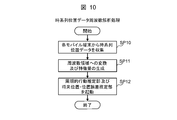
- FIG. 10 shows a specific processing flow of the time series position data frequency analysis process executed by the time series position data frequency analysis unit 30 in step SP1 of FIG. .
- the position information acquisition unit 40 obtains time-series position data (including the current position) for each day held by each mobile terminal 2 from each mobile terminal 2.
- the collected time-series position data for each user and each day is stored in the user position information table 22 (FIG. 3) (SP10).
- the position information acquisition unit 40 calls the feature value generation unit 41 (FIG. 2).
- the feature amount generation unit 41 When the feature amount generation unit 41 is called by the position information acquisition unit 40, for each user, the user's day for a certain period (one year in the present embodiment) stored in the user position information table 22 Are generated for each time-series position data (SP11).
- the feature value generation unit 41 performs feature analysis including the position and the moving speed, so that for each user, the time-series position data for each day is converted into a frequency domain by performing Fourier transform, and then daily. The feature amounts of the time-series position data are respectively generated.
- the feature quantity generation unit 41 firstly sets each piece of position information constituting the time series position data for each day of time series position data (in this embodiment, information on latitude and longitude every 5 minutes). Are converted into complex number data in which latitude data is a real part and longitude data is an imaginary part. In addition, the feature quantity generation unit 41 performs Fourier transform on these complex number data (time-series position data) to convert to frequency data. Further, the feature value generation unit 41 generates a feature value vector by linearly combining the real part and the imaginary part of each piece of position information converted into frequency data as described above for each time-series position data for one day. The generated feature quantity vector is used as the feature quantity of the time-series position data for one day.
- the latitude data of time-series position data may be linearly combined with longitude data as real values, and may be converted into frequency data by Fourier transform. In this case, since complex data is not used, it is possible to suppress the complexity of implementation of the processing program.
- the feature quantity generation unit 41 activates the periodic behavior estimation unit 31 and the future position / position error estimation unit 33 (SP12), whereby the time series position data frequency analysis unit 30 performs time series position data frequency analysis. The process ends.
- FIG. 11 shows a specific processing flow of the periodic behavior estimation processing executed by the periodic behavior estimation unit 31 in step SP2 of FIG.
- FIG. 11 shows the flow of periodic behavior estimation processing for one user, and the same periodic behavior estimation processing is executed for each user in order or in parallel.
- This periodic behavior estimation process is started when the periodic behavior estimation unit 31 is activated by the time-series position data frequency analysis unit 30.
- the visit periodicity calculation unit 42 is the target user (hereinafter, referred to as the following). This is called the target user), and the periodicity of the visit to each point visited so far (hereinafter referred to as the visit periodicity) is calculated (SP20).
- the visit periodicity calculation unit 42 acquires the frequency data of the time-series position data for each day of the target user from the feature value generation unit 41 of the time-series position data frequency analysis unit 30, and the acquired frequency data By performing the power spectrum analysis, the power spectrum density for each frequency as shown in FIG. 12A (that is, the strength of the periodicity (visiting periodicity) of movement of the target user) is calculated. Then, the visiting periodicity calculation unit 42 calls the feature point estimation unit 43 (FIG. 2).
- the feature point estimation unit 43 When called by the visit periodicity calculation unit 42, the feature point estimation unit 43 is stored in the power spectral density for each frequency calculated by the visit periodicity calculation unit 42 and the user position information table 22 (FIG. 3). Based on the movement trajectory of the target user as shown by a thick line in FIG. 12B recognized based on the time series position data of the target user for each day, a feature point that the target user visits periodically is detected, The attributes (such as home or work) of these characteristic points are estimated (SP21).
- FIG. 12B shows a three-week movement trajectory L (time transition of a position represented by latitude / longitude) of a certain target user.
- the power spectrum density for each frequency is as shown in FIG.
- the target user for example, works at the company only on weekdays (Monday to Friday) and does not work at the company on Saturday and Sunday. It is presumed that the person repeats a life that repeats the movement in a cycle of one week and the movement in a daily cycle of returning home every day.
- the feature point estimation unit 43 extracts a frequency value indicating that the power spectral density is greater than or equal to a predetermined value (the predetermined value is input in advance from the input / output device 18), and the extracted frequency indicates
- a frequency value indicating that the power spectral density is greater than or equal to a predetermined value (the predetermined value is input in advance from the input / output device 18)
- the extracted frequency indicates
- the point visited at a frequency (21 Hz) indicating that the cycle of movement is one day is home, and the site moves at a frequency (3 Hz) of seven days (day not visited). It is estimated that the workplace is a spot that is visited at a frequency (21 Hz) indicating that the movement cycle is 1 day).
- the movements (visits) to these points are managed by flags placed on a table for each combination of user ID and point ID (not shown). Moreover, you may make it estimate that the point where an object user is located at night on a weekday is a home.
- the feature point estimation unit 43 creates a feature point estimation result table 23X of the target user storing the attribute and position (latitude and longitude) of the target point of the target user estimated in this way (SP22).
- the periodic behavior estimation processing by the periodic behavior estimation unit 31 is completed by the processing described above. Then, the feature point estimation unit 43 of the periodic behavior estimation unit 31 calls the clustering execution unit 44 (FIG. 2) of the behavior pattern classification unit 32 thereafter.
- FIG. 13 shows a specific flow of behavior pattern classification processing executed by the behavior pattern classification unit 32 in step SP4 of FIG.
- FIG. 13 shows the flow of behavior pattern classification processing for one user, and the same behavior pattern classification processing is executed for each user in order or in parallel.
- This behavior pattern classification process is started when the clustering execution unit 44 is called by the feature point estimation unit 43 of the periodic behavior estimation unit 31 as described above.
- the clustering execution unit 44 is called by the feature point estimation unit 43, each time-series position data for each day of the target user generated by the feature amount generation unit 41 (FIG. 2) of the time-series position data frequency analysis unit 30.
- Clustering execution processing to classify these time-converted daily time-series position data into multiple clusters using clustering methods such as k-means method, vector quantization method, support vector machine, etc. Implement (SP30).
- the clustering execution unit 44 performs classification by sequentially setting the number of clusters to 2, 3, 4,..., And evaluates the similarity within the cluster and the separation between the clusters each time. The correct number of clusters.
- Similarity within a cluster is evaluated by, for example, the clustering result of each of the clusters 1 to M based on the feature amount of the time-series position data for each day of the target user and the distance of the cluster centroid between the clusters. .
- the feature amount of each time-series position data for each day in the cluster and between the clusters Evaluation is performed using the distance of the cluster centroid, the dispersion of each time-series position data for each day in the cluster, and the number of clusters.
- the Akaike information criterion is generally the order where L is the maximum likelihood and K is the number of degrees of freedom parameters. It is represented by
- the maximum likelihood L is, for example, It is represented by In the equation (2), RSS k represents the sum of squares of the distance from the cluster centroid of all members of the cluster k (here, time series position data for each day of the target user), and d represents the variance of the members.
- the number of degrees of freedom parameter K is, for example, It is represented by In Equation (3), M represents the number of clusters, and D represents the number of dimensions of the feature amount.
- evaluation criteria other than the Akaike information criterion for example, Bayesian Information Criterion (BIC)
- BIC Bayesian Information Criterion
- the separation between clusters is evaluated using, for example, the distance between the clusters.
- the distance between clusters is calculated, for example, by using a multi-class support vector machine for each boundary surface that can be separated from each other, and then the total value of the margin (distance) between each cluster is defined as MN.
- MN the total value of the margin between each cluster
- N represents the number of clusters.
- the intercluster average separation degree B (N) is an index representing the degree of separation between clusters as described above, and the larger this value, the more separated the clusters are.
- the average degree of separation between clusters may be any index that increases as long as the average distance between the clusters is large.
- the average of the distances between the cluster centroid sets ⁇ C k ⁇ A value may be applied.
- a user day classification information table 23Y (FIG. 5) is created (SP31). Then, the clustering execution unit 44 calls the cluster centroid locus generation unit 45 (FIG. 2).
- the cluster center-of-gravity locus generation unit 45 When called by the clustering execution unit 44, the cluster center-of-gravity locus generation unit 45 generates time-series position data (hereinafter referred to as cluster centroid time-series position data) of the cluster centroid of each cluster (SP32). .
- the cluster center-of-gravity locus generation unit 45 generates, for each cluster, complex number data in the frequency domain in which the first half data of the cluster center of gravity of the cluster obtained in the clustering execution process described above is a real part and the second half data is an imaginary part.
- the generated complex number data is converted into complex number data representing position information by inverse Fourier transform.
- the cluster centroid locus generation unit 45 generates time series position data of the cluster centroid with the real part of the complex number data (position information) as latitude and the imaginary part as longitude. It can be said that the time-series position data of the cluster centroid generated for each cluster at this time represents a typical movement pattern of the user in the cluster. It can be said that the fine difference between a plurality of movement trajectories classified into the same cluster represents a difference due to noise. By this processing, extraction of a typical movement pattern that eliminates the influence of noise is achieved.
- the cluster centroid locus generation unit 45 stores the cluster centroid time series position data of each cluster obtained in this way in the day classification information table 23Y generated in step SP31 (SP33).
- cluster centroid trajectory generator 45 causes the input / output device 18 (FIG. 1) to display a waveform based on the cluster centroid time series position data of each cluster as necessary, for example, in the format shown in FIG.
- FIG. 14 is an example when the time-series position data of the target user is classified into two clusters, and the locus of the cluster centroid of these clusters is displayed on three-dimensional coordinates with the latitude, longitude, and time axes, respectively.
- the example of a drawn display is shown. In this way, by drawing the locus of the cluster center of gravity on the three-dimensional coordinates with the latitude, longitude, and time axes respectively, representative movement patterns of users belonging to these clusters are displayed as waveforms that take the position and movement speed into consideration. can do.
- the cluster center-of-gravity locus generation unit 45 also displays the number of days belonging to each cluster.
- the cluster center-of-gravity locus generation unit 45 is based on the target user's feature point estimation result table 23X (FIG. 4) and the target user's day classification information table 23Y (FIG. 5) created as described above.
- the day attribute for each day of the week and each day is estimated, and the day attribute information table 23Z (FIG. 6) of the target user is created based on the estimation result (SP34).
- the cluster center-of-gravity locus generation unit 45 includes the position and attribute of each feature point registered in the feature point estimation result table 23X (FIG. 4) of the target user and the day classification information table 23Y (FIG. 5) of the target user. For example, if the cluster centroid of a cluster stays at a feature point estimated to be a workplace for a certain period of time based on the cluster centroid time-series position data of each cluster stored in The date is estimated to be a working day, otherwise the date belonging to the cluster is estimated to be a non-working day.
- the cluster center-of-gravity locus generation unit 45 for example, a calendar that can identify whether it is a working day or a non-working day for each day as shown in FIG. 50) is created.
- the date when the time series position data of the target user is collected is “2/22”, and the current date is “3/24”. It is an example in the case where it is in a state where it cannot be determined.
- the cluster center-of-gravity locus generation unit 45 determines, for each day of the week, when the number of days estimated as a working day is greater than the day estimated as a non-working day, Day attributes are estimated as work days, and other day attributes of days of the week and dates are estimated as non-work days. Further, the cluster center-of-gravity locus generation unit 45, for example, aggregates the day attributes for the same day of each month, and when the number of days estimated to be non-working days is large for the days, the day of the day is estimated. The day attribute is estimated as a non-working day, and the day attribute of other days is estimated as a working day. Then, the cluster center-of-gravity locus generation unit 45 creates the date attribute information table 23Z based on such an estimation result.
- the action pattern classification process by the action pattern classification unit 32 is completed by the above processing.
- the cluster center-of-gravity locus generation unit 45 thereafter notifies the information distribution event determination / execution unit 21 (FIG. 2) that the action pattern classification process has ended.
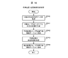
- FIG. 16 shows specific processing of future position / position error estimation processing executed by the future position / position error estimation unit 33 (FIG. 2) in step SP3 of FIG. Shows the flow.
- FIG. 16 shows the flow of the future position / position error estimation process for one user, and the same future position / position error estimation process is executed for each user in order or in parallel.
- the future position / position error estimation process is started when the future position / position error estimation unit 33 is activated by the time-series position data frequency analysis unit 30.
- the user position prediction unit 46 From the information table 22 (FIG. 3), position data for the N periods nearest to the target user is acquired (SP40).
- One period is a period in which the mobile terminal 2 acquires position data. In the present embodiment, it is 5 minutes as described above.
- the user position predicting unit 46 sequentially predicts the position of the target user after one period has elapsed from the current time based on the acquired position data (SP41).
- the user position prediction unit 46 calculates the following equation based on the position data for the N period of the target user acquired from the user position information table 22.
- An autoregression model (AR (Auto Regression) model) given by
- the predicted location of the target user in y t is the time t
- c is a constant
- P is the model of order
- ⁇ i ( ⁇ 1, ?? , ⁇ P) is the model parameters
- epsilon t is Represents an error.
- an optimal value can be calculated using the Akaike information criterion (AIC) as an index, and the value of each parameter ⁇ i ( ⁇ 1 ,..., ⁇ P ) For example, the optimum value can be calculated for each set using the Yulewalker method.
- the user position prediction unit 46 uses the position data for the N period of the target user read from the user position information table, and uses the autoregressive model of the equation (5), as shown in FIG. The future position of the target user after one period has been calculated. Further, the user position prediction unit 46 uses the position data for the N periods that are old in order from the future position starting from the calculated future position of the target user, and finally uses the autoregressive model of equation (5). The future position of the user after one period has elapsed from the calculated future position of the target user is calculated. The user position predicting unit 46 sequentially calculates the future positions of the target user after one period has elapsed from the current time by repeating such calculation.
- the number of periods ahead to be predicted is determined according to, for example, the interval at which information is distributed.
- an information distribution interval input in advance from the input / output device 18 is set to a period length for performing future position prediction.
- a delay occurs in information distribution to the user due to a communication delay between user position information acquisition and distribution.
- future position prediction ahead for the information distribution interval it is possible to determine the information to be distributed at the time of the next information distribution in consideration of the point where the user is likely to be at that time, so the information distribution delay to the user is reduced. Can be suppressed.
- the current time is used as the future time, the current location can be predicted.
- the position prediction of one period ahead is performed to suppress the error from the actual user's current position due to the communication delay of information acquisition, and the actual user's position at the time of sudden positioning error of GPS positioning occurs. It is possible to suppress an error from the current position.
- the user position predicting unit 46 associates the future position of the target user calculated in this way for a certain period with the future date and time (time stamp) corresponding to these future positions. 7) (SP42). The user position predicting unit 46 then calls the position error range estimating unit 47 (FIG. 2).
- the position error range estimation unit 47 estimates the error range of the future position for each period of the target user predicted by the user position prediction unit 46 as described above (SP43).
- conditional volatility data fluctuation rate
- GARCH Generalized Auto Regressive Conditional Heteroscedasticity
- the position error range estimation unit 47 stores the error range of the future position of the user for each period estimated in this way in the user position prediction information table 24 in association with the corresponding future time (SP44).
- the future position / position error estimation process by the future position / position error estimation unit 33 is completed by the above processing.
- the position error range estimation unit 47 thereafter notifies the information distribution event determination / execution unit 21 (FIG. 2) that the future position / position error estimation process has been completed.
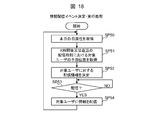
- FIG. 18 shows a specific processing flow of the information distribution event determination / execution processing executed by the information distribution event determination / execution unit 21 in step SP5 of FIG. .
- FIG. 18 shows the flow of information distribution event determination / execution processing for one user, and the same information distribution event determination / execution processing is executed for each user in order or in parallel.
- This information distribution event determination / execution process is performed when the information distribution event determination / execution unit 21 notifies the fact that the above-described behavior pattern classification process transmitted from the cluster centroid locus generation unit 45 of the behavior pattern classification unit 32 is completed.
- the process is started when both the notification of the end of the above-described future position / position error estimation process transmitted from the position error range estimation unit 47 of the future position / position error estimation unit 33 is received.
- the information distribution event determination unit 48 acquires today's day attribute from the day attribute information table 23Z (FIG. 6) (SP50).
- the information distribution event determination unit 48 distributes information to the user at a predetermined time interval, the time specified in advance by the user after a predetermined distribution cycle time (X time) has elapsed.
- X time a predetermined distribution cycle time
- the predicted position (future position) of the target user at the most recent distribution scheduled time from the current time is the user position. Obtained from the prediction information table 24 (SP51).
- the information distribution event determination unit 48 determines the feature point estimation result based on the current day attribute (working day or non-working day) of the target user acquired in step SP50 and the predicted position of the target user acquired in step SP51.
- the information type of the distribution candidate to be directed to the target user (hereinafter referred to as the distribution candidate information type) is determined (SP52).
- the position coordinates of each point ID in the feature point estimation result table 23X (FIG.
- the current or future position coordinates acquired in step SP51, the estimation error acquired in step SP51, and the preset point-by-point It is determined whether or not the user is at a predetermined feature point by processing using an allowable error.
- a circle having a current or future position coordinate as a center and an estimation error as a radius, and a circle having a position ID of the point ID as a center and an allowable error at the point as a radius are calculated. It is determined whether the two calculated circles overlap. If there is an overlap, the point is determined as the user's presence point. The determination process is repeated for all points with the point ID to determine the user's location.
- a value for a predetermined point is input from the input / output device 18 in advance.
- GPS positioning causes an error from the actual mobile terminal position due to radio wave interference caused by various obstacles in the vicinity of the mobile terminal.
- the values are compared after rounding to the specified decimal point of the latitude and longitude of the current coordinates and future position coordinates and the position coordinates of each point ID, and whether the points match Processing such as determining the presence or absence may be simplified.
- the information distribution event determination unit 48 determines that the current day attribute of the target user acquired in step SP50 is “working day”, and the target user after X hours acquired in step SP51 or the latest predetermined distribution time When the predicted position is “workplace” and the latest delivery time after X hours or in advance is “11:00”, the delivery candidate information table 25 is referred to and the delivery candidate information type is set to “workplace”. “Lunch information near”.
- the information distribution event determination unit 48 thereafter waits for the X time to elapse or the latest distribution scheduled time specified in advance (SP53). Then, the information distribution event determination unit 48 calls the information distribution event execution unit 49 when X time has passed or the latest distribution scheduled time is reached.
- the information distribution event execution unit 49 When called by the information distribution event determination unit 48, the information distribution event execution unit 49 acquires distribution information that matches the distribution candidate information type determined by the information distribution event determination unit 48 from the distribution information database 26, and acquires the acquired distribution. Information is distributed to the target user (SP54).
- step SP50 the processing returns to step SP50, and thereafter, the processing of step SP50 to step SP54 is repeated as necessary.
- this information distribution system since an autoregressive model is generated based on the latest time-series position data of the user and the future position of the user is predicted, the user can perform actions that deviate from regular actions.
- the future position of the user can be predicted with a certain degree of accuracy, and thus appropriate information corresponding to the current position of the user can be distributed to the user.
- the mobile communication body is a portable communication terminal device such as the mobile terminal 2
- the present invention is not limited to this, for example, a car
- the present invention can also be applied to a mobile communication body other than a portable communication terminal device such as a navigation system.
- each The mobile communication body may detect its own position by some means such as a sensor other than the positioning device 14, and the mobile communication body itself is not equipped with a function for positioning its own position,
- the external device may measure the position of each mobile communication body with the monitoring camera or the like, and the information distribution apparatus 3 may collect the result (position information of each mobile communication body).
- the Fourier transform is applied as a conversion method for converting each time-series position data into frequency domain frequency data in the clustering execution processing.
- a transform method other than Fourier transform such as wavelet transform, can be widely applied.
- the position information (including time-series position data) collected by the information distribution device 3 from each mobile terminal 2 is composed of only two coordinate values of latitude and longitude.
- the present invention is not limited to this.
- position information including time-series position data
- the time-series position data may be converted into complex number data so as to be distributed to either the part or the imaginary part.
- the present invention is not limited thereto, and for example, the above-described implementation
- the present invention can also be applied to a system that predicts the future position of a taxi by the same method as in the above form and controls the position of the taxi based on the prediction result.
- the time series position data including the time series position information of the mobile communication body is collected, and the rules of the user having the mobile communication body based on the collected time series position data of the mobile communication body It is possible to estimate the behavior and plan the optimum information distribution for the user or the like, or to plan the user to control the user to the optimum state.
- the present invention can be widely applied to an information distribution apparatus that distributes information to a mobile communication body equipped with a positioning function for acquiring position data of its current position.
Landscapes
- Engineering & Computer Science (AREA)
- Theoretical Computer Science (AREA)
- Business, Economics & Management (AREA)
- Physics & Mathematics (AREA)
- General Physics & Mathematics (AREA)
- Signal Processing (AREA)
- Computer Networks & Wireless Communication (AREA)
- Accounting & Taxation (AREA)
- Finance (AREA)
- Strategic Management (AREA)
- Development Economics (AREA)
- General Engineering & Computer Science (AREA)
- Databases & Information Systems (AREA)
- Data Mining & Analysis (AREA)
- General Business, Economics & Management (AREA)
- Entrepreneurship & Innovation (AREA)
- Game Theory and Decision Science (AREA)
- Economics (AREA)
- Marketing (AREA)
- Software Systems (AREA)
- Remote Sensing (AREA)
- Telephonic Communication Services (AREA)
- Information Transfer Between Computers (AREA)
- Mobile Radio Communication Systems (AREA)
- Management, Administration, Business Operations System, And Electronic Commerce (AREA)
- Information Retrieval, Db Structures And Fs Structures Therefor (AREA)
Abstract
【課題】 ユーザに適した情報を配信する等の効果的な施策を計画することができる情報処理装置及び方法を提案する。 【解決手段】 移動通信体の時系列の位置情報でなる時系列位置データを収集し、収集した移動通信体の時系列位置データに基づいて当該移動通信体のユーザの規則的行動を推定するようにした。
Description
本発明は情報処理装置及び方法に関し、例えば、スマートフォンや携帯電話端末などのモバイル端末に対してそのユーザに有益な情報を配信する情報配信システムに適用して好適なものである。
近年、携帯電話機等のモバイル端末の多くはGPS(Global Positioning System)などの測位機能を備えている。これにより、モバイル端末のユーザは、モバイル端末の測位結果に基づいて現在位置情報を取得することができると共に、測位結果をネットワーク経由で通信事業者やサービス事業者の情報配信装置に送信することで、ユーザの現在位置に応じた様々なサービス情報を受信することが可能となる。
なお、ユーザの位置情報を取得する技術として、特許文献1に開示された方法が知られている。この特許文献1に開示されたユーザ位置の取得方法は、携帯電話機への複数信号送信による三角測量や、複数信号の信号強度、異なる信号の着信時刻の差、異なる信号の着信角の差、GPS信号、及び、これらの組合せに基づき、携帯電話機の緯経度座標位置を捕捉するものである。
こうしたユーザの一情報に応じたサービス情報配信を効果的に行うためには、ユーザが将来訪れる場所及びその時間に応じたサービス情報の配信を行うことが求められる。このためには、ユーザが将来訪れる可能性が高いエリアを予測した上でサービス情報の配信を行うことが望ましい。
このようなユーザが将来訪れる可能性が高いエリアを予測し、そのエリアに応じたサービス情報を配信する技術として、従来、特許文献2~特許文献4に開示された技術が提案されている。
例えば、特許文献2では、ユーザの滞在地間遷移パターンを抽出し、滞在地間遷移パターンごとに遷移パターンの出現確率を対応付けた滞在地間遷移モデルを構築する。そして過去の滞在滞留時系列データと、他の携帯端末に係る滞在滞留時系列データとの間の最長一致部分系列長に基づいて、携帯端末の移動経路に類似した移動経路をとる携帯端末を検索することにより、ユーザの将来位置を予測することが開示されている。
また特許文献3には、ユーザの滞在時間又は滞在頻度が多い上位2つの地点を自宅又は職場といったプライベート関連地点として決定し、平均滞在時間が閾値以上の地点をユーザが立ち寄ることの多いパブリック関連地点として決定することが開示され、特許文献4には、ユーザの位置に応じた適切な広告候補を事前にデータベース化しておき、ユーザの位置と時間帯とに応じて適切な広告を配信することが開示されている。
特許文献2や特許文献3や特許文献4には、あるユーザの将来経路や滞在地点を自己又は他者の過去の経路データを用いて予測し、予測した経路情報を基に情報配信などのイベントを発生させることが開示されている。
ところが、人の行動パターンは、通常、勤務日であるか又は休日であるか等、日や時間帯の違いによって異なる。また同じ勤務日であっても、例えば終業後に習い事に通っている場合などには曜日によっても行動パターンが異なる。そのため、過去の全期間の経路データからの地点毎の存在確率を予測する方法では、こうした日や時間帯の違いによる行動の違いを予測することができないという問題がある。モバイル端末のユーザに対して効果的な情報配信を行うためには個々のユーザの習慣的な行動パターンを踏まえた上で、情報配信の効果が期待できる時間帯に効果が期待できる情報を配信することが望まれる。
本発明は以上の点を考慮してなされたもので、ユーザに適した情報を配信する等の効果的な施策を計画可能な情報処理装置及び方法を提案しようとするものである。
かかる課題を解決するため本発明においては、情報処理装置において、移動通信体の時系列の位置情報でなる時系列位置データを収集し、収集した前記移動通信体の前記時系列位置データに基づいて当該移動通信体のユーザの規則的行動を推定する規則的行動推定部を設けるようにした。
また本発明においては、情報処理方法において、移動通信体の時系列の位置情報でなる時系列位置データを収集し、収集した前記移動通信体の前記時系列位置データに基づいて当該移動通信体のユーザの規則的行動を推定する第1のステップを設けるようにした。
本情報処理装置及び方法によれば、ユーザの規則的な行動に合わせた情報配信等の効率的な情報処理を行うことができる。
本発明によれば、ユーザに適した情報を配信する等の効果的な施策を計画することができる。
以下図面について、本発明の一実施の形態を詳述する。
(1)本実施の形態による情報配信システムの構成
図1において、1は全体として本実施の形態による情報配信システムを示す。この情報配信システム1は、1又は複数のモバイル端末2と情報装置であるところの情報配信装置3とを備えて構成され、これらが無線基地局4及び交換局5などから構成される無線通信網と、ネットワーク6とを介して通信自在に接続される。
図1において、1は全体として本実施の形態による情報配信システムを示す。この情報配信システム1は、1又は複数のモバイル端末2と情報装置であるところの情報配信装置3とを備えて構成され、これらが無線基地局4及び交換局5などから構成される無線通信網と、ネットワーク6とを介して通信自在に接続される。
モバイル端末2は、測位機能が搭載された携帯電話機などの携帯型通信端末装置から構成され、CPU(Central Processing Unit)10、記憶装置11、通信装置12、入出力装置13及び測位装置14などを備える。
CPU10は、モバイル端末2全体の動作制御を司るプロセッサである。また記憶装置11は、半導体メモリなどから構成され、主として各種プログラムを記憶保持するために利用される。記憶装置11に格納されたプログラムをCPU10が実行することにより、後述のようなモバイル端末2全体としての各種処理が実行される。通信装置12は、所定の無線通信規格に準拠した通信方式で無線基地局4との間で無線通信を行う機能を有する。
入出力装置13は、そのモバイル端末2の利用者(以下、これを単にユーザと呼ぶ)が各種操作入力を行うためのハードウェアである入力装置と、画像や音声を出力するハードウェアである出力装置とから構成される。入力装置としては、例えば、ボタン及び十字キーや、タッチパネルなどが適用され、出力装置としては、例えば液晶パネル及びスピーカなどが適用される。
測位装置14は、複数のGPS衛星から送信される信号を受信し、受信したこれらの信号に基づいてモバイル端末2の現在位置を測位する機能を有する。測位装置14により測位されたモバイル端末2の現在位置(以下、そのモバイル端末2を携帯するユーザの現在位置とする)を表す位置データは、記憶装置11に蓄積され、蓄積された時系列の位置データが時系列位置データとして通信装置12により無線通信網及びネットワーク6を介して情報配信装置3に送信される。
無線基地局4は、モバイル端末2と直接交信を行う携帯電話網の末端施設であり、モバイル端末2から発信された無線信号を携帯電話網の通信規格に準拠した信号に変換して交換局5に出力し、又は、交換局5から与えられた信号を上記無線通信規格に準拠した無線信号に変換して送信先のモバイル端末2に送信する。
交換局5は、携帯電話網の一部を構成する施設であり、無線基地局4から与えられた信号をネットワーク6の通信規格に準拠した方式の信号に変換してネットワーク6を介して情報配信装置3に送信し、又は、情報配信装置3からネットワーク6を介して与えられた信号を無線通信網の通信規格に準拠した信号に変換して無線基地局4に出力する。
ネットワーク6は、例えばLAN(Local Area Network)、インターネット、公衆回線又は専用回線などから構成される。このネットワーク6を介した交換局5及び情報配信装置3間の通信は、例えばネットワーク6がLANやインターネットである場合にはTCP/IP(Transmission Control Protocol/Internet Protocol)プロトコルに従って行われる。
情報配信装置3は、各モバイル端末2から収集した時系列位置データに基づいて、ユーザの現在位置やそのユーザの嗜好に応じた最適なサービス情報を配信するサーバ装置であり、CPU15、記憶装置16、通信装置17及び入出力装置18を備えて構成される。
CPU15は、情報配信装置3全体の動作制御を司るプロセッサである。また記憶装置16は、例えば半導体メモリやハードディスク装置などから構成され、各種プログラムや各種データを保持するために利用される。記憶装置16に格納されたプログラムをCPU15が実行することにより、後述のような情報配信装置3全体としての各種処理が実行される。
通信装置17は、情報配信装置3がネットワーク6を介して交換局5との間で通信を行う際のプロトコル制御を行うインタフェースであり、NIC(Network Interface Card)などから構成される。
入出力装置18は、入力装置及び出力装置から構成される。入力装置は、ユーザが各種操作入力を行うためのハードウェアであり、例えば、キーボード、マウス又はタッチパネルなどが適用される。また出力装置は、画像や音声を出力するハードウェアであり、例えば液晶ディスプレイ及びスピーカなどが適用される。
(2)本実施の形態による情報配信機能
次に、情報配信装置3に搭載された本実施の形態による情報配信機能について説明する。この情報配信機能は、ユーザごとに、そのユーザのある期間(例えば1年)における日ごとの時系列位置データに基づいてユーザの規則的行動を予測し、予測結果に基づいてそのユーザに対する情報配信を計画立案する機能である。
次に、情報配信装置3に搭載された本実施の形態による情報配信機能について説明する。この情報配信機能は、ユーザごとに、そのユーザのある期間(例えば1年)における日ごとの時系列位置データに基づいてユーザの規則的行動を予測し、予測結果に基づいてそのユーザに対する情報配信を計画立案する機能である。
このような情報配信機能を実現するための手段として、情報配信装置3の記憶装置16には、図2に示すように、プログラムとして、規則的行動推定部20及び情報配信イベント決定・実行部21が格納されると共に、図1に示すように、必要な情報を管理するためのテーブル及びデータベースとして、ユーザ位置情報テーブル22、ユーザ属性情報データベース23、ユーザ位置予測情報テーブル24、配信候補情報テーブル25及び配信情報データベース26が格納されている。
規則的行動推定部20は、ユーザの過去の時系列位置データに基づいてそのユーザの規則的な行動パターンを把握し、そのユーザの将来の位置を予測する機能を有するプログラムであり、図2に示すように、時系列位置データ周波数解析部30、周期的行動推定部31、行動パターン分類部32及び将来位置・位置誤差推定部33を備えて構成される。
このうち時系列位置データ周波数解析部30は、各ユーザについて、そのユーザの日ごとの時系列位置データを周波数解析し、これら日ごとの時系列位置データの特徴量を算出する機能を有するモジュール群であり、位置情報取得部40及び特徴量生成部41から構成される。
位置情報取得部40は、各モバイル端末2の測位装置14(図1)により一定時間間隔(例えば5分間隔)で測位されたユーザの位置情報(緯度及び経度)の時系列位置データ(1日分の位置情報)をユーザの移動情報として収集する機能を有するモジュールである。位置情報取得部40は、各モバイル端末2に対して定期的又は非定期に時系列位置データの転送要求を送信することにより、これらモバイル端末2が保持する日ごとの時系列位置データを収集し、収集した時系列位置データをユーザ位置情報テーブル22に登録して管理する。ただし、各モバイル端末2がかかる時系列位置データを定期的又は非定期に情報配信装置3に送信し、位置情報取得部40がこれらの時系列位置データをユーザ位置情報テーブル22に登録して管理するようにしても良い。
特徴量生成部41は、位置情報取得部40が取得した各ユーザの時系列位置データに基づいて、ユーザごとに、そのユーザの日ごとの時系列位置データの特徴量をそれぞれ生成する機能を有するモジュールである。
周期的行動推定部31は、ユーザごとに、そのユーザの周期的な行動を検出する機能を有するモジュール群であり、訪問周期性算出部42及び特徴地点推定部43から構成される。
訪問周期性算出部42は、ユーザごとに、そのユーザの日ごとの時系列位置データに基づいて、そのユーザの行動の周期性を算出する機能を有するモジュールである。
また特徴地点推定部43は、訪問周期性算出部42により算出されたユーザの行動の周期性に基づいて、そのユーザが周期的に訪問する地点(以下、適宜、これを特徴地点と呼ぶ)ごとの訪問の周期性(以下、これを訪問周期性と呼ぶ)を算出し、算出結果に基づいてその特徴地点の属性(自宅又は職場など)を推定する機能を有するモジュールである。特徴地点推定部43は、推定した各地点の属性及び位置(緯度及び経度)を図4について後述する特徴地点推定結果テーブル23Xに格納して管理する。
行動パターン分類部32は、ユーザの日ごとの行動を幾つかの行動パターンに分類する機能有するモジュール群であり、クラスタリング実行部44及びクラスタ重心軌跡生成部45から構成される。
クラスタリング実行部44は、ユーザごとに、時系列位置データ周波数解析部30により生成されたそのユーザの日ごとの時系列位置データの特徴量に基づいて、そのユーザの日ごとの時系列位置データを複数のクラスタに分類するクラスタリング処理を実行する機能を有するモジュールである。クラスタリング実行部44は、かかるクラスタリング処理の処理結果を図5について後述するユーザ属性情報データベース23の日分類情報テーブル23Yに格納する。
またクラスタ重心軌跡生成部45は、ユーザごとに、クラスタリング実行部44により生成されたそのユーザのクラスタごとに、そのクラスタ重心の軌跡を生成し、生成した各クラスタのクラスタ重心の軌跡を日分類情報テーブル23Yに格納する機能を有するモジュールである。クラスタ重心軌跡生成部45により生成されたクラスタごとのクラスタ重心の軌跡が必要に応じて入出力装置18(図1)に表示される。またクラスタ重心軌跡生成部45は、特徴地点推定結果テーブル23Xに格納された各特徴地点の属性及び位置と、日分類情報テーブル23Yに格納された各クラスタのクラスタ重心の軌跡とに基づいて曜日ごと及び日にちごとにその曜日及び日にちが勤務日であるかの属性(以下、これを日属性と呼ぶ)を推定し、推定結果を図6について後述する日属性情報テーブル23Zに格納する。
将来位置・位置誤差推定部33は、ユーザごとに、そのユーザの一定時間(例えば5分)ごとの将来の位置(以下、これを将来位置と呼ぶ)及びこれら将来位置の予測誤差を推定する機能を有するモジュールであり、ユーザ位置予測部46及び位置誤差範囲推定部47から構成される。
ユーザ位置予測部46は、ユーザの将来位置を予測する機能を有するモジュールである。ユーザ位置予測部46により予測されたユーザの将来位置は、図7について後述するユーザ位置予測情報テーブル24に格納されて管理される。また位置誤差範囲推定部47は、ユーザ位置予測部46が予測したユーザの将来位置の誤差範囲を推定する機能を有するモジュールである。位置誤差範囲推定部47により推定された誤差範囲もユーザ位置予測情報テーブル24に格納されて管理される。
さらに情報配信イベント決定・実行部21は、ユーザごとに、そのユーザに配信すべき情報を決定し、決定した情報をそのユーザに配信する機能を有するプログラムである。この情報配信イベント決定・実行部21は、図2に示すように、情報配信イベント決定部48及び情報配信イベント実行部49から構成される。
情報配信イベント決定部48は、ユーザごとに、将来位置・位置誤差推定部33により予測されたそのユーザの将来位置と、図8について後述する配信候補情報テーブル25とに基づいて、そのユーザに配信すべき情報を決定する機能を有するモジュールである。また情報配信イベント実行部49は、情報配信イベント決定部48の決定結果に従って各ユーザに情報をそれぞれ配信する情報配信イベントを実行する機能を有するモジュールである。
一方、ユーザ位置情報テーブル22は、図2について上述した行動パターン分類部32の位置情報取得部40により各モバイル端末2から収集された各ユーザの日ごとの時系列位置データを管理するために利用されるテーブルであり、図3に示すように、ユーザID欄22A、項目欄22B及び値欄22Cを備えて構成される。
そしてユーザID欄22Aには、情報配信装置3が時系列位置データを収集した各モバイル端末2のユーザに付与されたそのユーザに固有の識別子(ユーザID)が格納される。
また項目欄22Bは、タイムスタンプ欄22D、位置情報欄22Eに区分されると共に、位置情報欄22Eは、さらに緯度欄22F、経度欄22G及び位置測定誤差欄22Hに区分され、値欄22Cには、対応する項目の値が格納される。
具体的に、タイムスタンプ欄22Dに対応する値欄22Cには、対応するユーザの時系列位置データを構成する一定時間(図3では5分)ごとの位置データをモバイル端末2の測位装置14(図1)が取得した時刻が古い順にそれぞれ並べたリストが格納され、緯度欄22F及び経度欄22Gにそれぞれ対応する値欄22Cには、これらの時刻に測位装置14が取得した緯度及び経度のうちの対応する一方の値が古い順に並べたリストが格納される。さらに位置測定誤差欄22Hに対応する値欄22Cには、かかる各時刻における測位装置14の位置測定誤差を認識できる場合のその位置測定誤差が古い順に並べたリストが格納される。
従って、図3の例の場合、ユーザIDが「1」のユーザについては、時系列位置データとして「2015-01-01 09:00」、「2015-01-01 09:05」、……に測位を行った位置データを収集しており、「2015-01-01 09:00」の測位結果は緯度が「35.451414」、経度が「139.632177」で位置測定誤差が「10.0m」であり、「2015-01-01 09:05」の測位結果は緯度が「35.451416」、経度が「139.635137」で位置測定誤差が「10.0m」であったことが示されている。
ユーザ属性情報データベース23は、図4に示す特徴地点推定結果テーブル23X、図5に示す日分類情報テーブル23Y及び図6に示す日属性情報テーブル23Zから構成される。
特徴地点推定結果テーブル23Xは、上述した周期的行動推定部31(図2)の特徴地点推定部43(図2)により推定されたそのユーザに関する各特徴地点の属性(自宅又は職場など)及び位置を管理するために利用されるテーブルであり、ユーザごとに作成される。この特徴地点推定結果テーブル23Xは、図4に示すように、地点ID欄23XA、属性欄23XB、項目欄23XC及び値欄23XDを備えて構成される。
そして地点ID欄23XAには、特徴地点推定部43により推定された対応するユーザに関する各特徴地点に対してそれぞれ付与されたその特徴地点に固有の識別子(地点ID)が格納され、属性欄23XBには、特徴地点推定部43により推定されたその特徴地点の属性が格納される。
また項目欄23XCは、緯度欄23XE及び経度欄23XFに区分され、値欄23XDに対応する項目の値が格納される。具体的に、緯度欄23XEに対応する値欄23XDには対応する特徴地点の緯度が格納され、経度欄23XFに対応する値欄23XDには対応する特徴地点の経度が格納される。
従って、図4の例の場合、地点IDが「1」の特徴地点は特徴地点推定部43により「自宅」と推定され、その位置は緯度が「35.451414」、経度が「139.632177」であることが示されている。
日分類情報テーブル23Yは、行動パターン分類部32(図2)のクラスタリング実行部44(図2)により実行されたクラスタリング処理の処理結果及びクラスタ重心軌跡生成部45により生成された各クラスタのクラスタ重心の軌跡を管理するために利用されるテーブルであり、ユーザごとに作成される。この日分類情報テーブル23Yは、図5に示すように、クラスタID欄23YA、項目欄23YB及び値欄23YCを備えて構成される。
そしてクラスタID欄23YAには、かかるクラスタリング処理により生成された各クラスタにそれぞれ付与されたそのクラスタに固有の識別子(クラスタID)が格納される。
また項目欄23YBは、サンプル日数欄23YD、サンプル日IDリスト欄23YE及びクラスタ重心欄23YFに区分されると共に、クラスタ重心欄23YFは、緯度欄23YG及び経度欄23YHに区分されており、値欄23YCには、対応する項目の値がそれぞれ格納される。
具体的に、サンプル日数欄23YDに対応する値欄23YCには、所定期間(本実施の形態では1年であるが、1年分のデータが存在しない場合には存在する分の期間)内で対応するクラスタに属する日の数(日数)が格納され、サンプルユーザIDリスト欄23YEに対応する値欄23YCには、そのクラスタに属する日の日にちが列記されたリストが格納される。またクラスタ重心欄23YFの緯度欄23YGに対応する値欄23YCには、対応するクラスタに属する各日の同じ時刻に収集された位置データに基づき算出されたそのクラスタの重心位置(以下、これをクラスタ重心位置と呼ぶ)の緯度の一覧でなるリストが格納され、クラスタ重心欄23YFの経度欄23YHに対応する値欄23YCには、かかるクラスタ重心位置の経度の一覧でなるリストが格納される。
従って、図5の例の場合、「1」というクラスタIDが付与されたクラスタについては、そのクラスタに属する日の日数が「23」、これら日の日にちが「1,2,3,……,23」であり、各時刻におけるクラスタ重心の緯度及び経度が順番に「35.451414,139.632177」、「35.451416,139.635137」、……であったことが示されている。
日属性情報テーブル23Zは、特徴地点推定部43(図2)により推定されたそのユーザの日属性情報を管理するために利用されるテーブルであり、ユーザごとに作成される。この日属性情報テーブル23Zは、図6に示すように、日タイプ欄23ZA及び勤務日フラグ欄23ZBから構成される。
そして日タイプ欄23ZAには、各曜日(月曜日~日曜日)及び特定の日にち(第5月曜日など)といった日のタイプが格納され、勤務日フラグ欄23ZBには、対応する日タイプを有する曜日又は日にちが勤務日であるかといった、対応する日タイプの勤務に関する属性(以下、これを日属性と呼ぶ)を表すフラグ(以下、これを勤務日フラグと呼ぶ)が格納される。なお勤務日フラグは、対応する曜日又は日にちが勤務日と推定された場合には「1」、勤務日でないと推定された場合には「0」に設定される。
従って、図6の例の場合、対応するユーザが、1週間のうち「月曜日」から「金曜日」までが勤務日(勤務日フラグが「1」)で、「土曜日」及び「日曜日」が非勤務日(勤務日フラグが「0」)であり、これ以外にも「第5月曜日」も非勤務日であると推定されたことが示されている。
ユーザ位置予測情報テーブル24は、将来位置・位置誤差推定部33(図2)のユーザ位置予測部46(図2)により予測された将来の一定時間ごと(5分ごと)の各ユーザの位置(将来位置)と、位置誤差範囲推定部47(図2)により推定されたこれら将来位置の誤差とを管理するために利用されるテーブルであり、図7に示すように、ユーザ位置情報テーブル22(図3)と同様の構成を有する。
そしてユーザ位置予測情報テーブル24のユーザID欄24Aには、情報配信装置3が時系列位置データを収集した各モバイル端末2のユーザに付与されたそのユーザのユーザIDが格納される。
また項目欄24Bは、タイムスタンプ欄24D、位置情報欄24Eに区分されると共に、位置情報欄24Eは、さらに緯度欄24F、経度欄24G及び推定誤差欄24Hに区分され、値欄24Cには、対応する項目の値が格納される。
具体的に、タイムスタンプ欄24Dに対応する値欄24Cには、対応するユーザについて位置が予測された将来の一定時間(5分)刻みの時刻(以下、これらを将来時刻と呼ぶ)を早い順に並べたリストが格納され、緯度欄24F及び経度欄24Gにそれぞれ対応する値欄24Cには、対応するユーザがこれらの将来時刻にユーザが位置するとそれぞれ予測される緯度(緯度に対応する値欄24Cの場合)又は経度(経度に対応する値欄24Cの場合)の値を対応する時刻が早い順に並べたリストが格納される。さらに推定誤差欄24Hに対応する値欄24Cには、位置誤差範囲推定部47により推定されたかかる各将来の時刻における対応するユーザの将来位置の誤差を対応する将来時刻が早い順に並べたリストが格納される。
従って、図7の例の場合、ユーザIDが「1」のユーザについては、将来時刻である「2015-01-01 09:00」、「2015-01-01 09:05」、……におけるそのユーザの将来位置が格納されており、「2015-01-01 09:00」には緯度が「35.451414」、経度が「139.632177」の位置に位置していると予測され、その位置誤差が「10.0m」であり、「2015-01-01 09:05」には緯度が「35.451416」、経度が「139.635137」の位置に位置していると予測され、その位置誤差が「10.0m」であることが示されている。
配信候補情報テーブル25は、予測されるユーザの将来位置等に応じてそのユーザに配信すべき配信候補の情報(以下、これを配信候補情報と呼ぶ)を管理するために利用されるテーブルであり、図8に示すように、配信情報ID欄25A、属性項目欄25B及び配信情報内容欄25Cを備えて構成される。
そして配信情報ID欄25Aには、これら配信候補情報に対してそれぞれ付与されたその配信候補情報に固有の識別子(配信情報ID)が格納され、配信情報内容欄25Cには、対応する配信情報IDが付与された配信候補情報の内容が格納される。
また属性項目欄25Bは、日属性欄25D、時間帯欄25E、職場フラグ欄25F及び自宅フラグ欄25Gに区分されており、日属性欄25Dには、対応する配信候補情報を配信すべき日に関する情報(本実施の形態では「勤務日」又は「非勤務日」)が格納され、時間帯欄25Eには、その配信候補情報を配信すべき時間帯が格納される。また職場フラグ欄25Fには、ユーザが職場にいると予測される場合に対応する配信候補情報を送信するか否かを表すフラグ(送信すべき場合には「1」、送信すべきでない場合には「0」)が格納され、自宅フラグ欄25Gには、ユーザが自宅にいると予測される場合に対応する配信候補情報を送信するか否かを表すフラグ(送信すべき場合には「1」、送信すべきでない場合には「0」)が格納される。
従って、図8の例の場合、ユーザの「勤務日」の「9:00~12:00」の時間帯でそのユーザが職場にいると予測される場合(「職場フラグ欄の値が「1」で自宅フラグ欄の値が「0」)ときには、そのユーザに対して配信すべき情報の候補(配信候補情報)として「職場付近のランチ情報」が規定されていることが示されている。
配信情報データベース26は、本実施の形態の情報配信サービスを利用してユーザにランチ情報やディナー情報などの情報配信を依頼したスポンサごとに、そのスポンサが配信を依頼した情報の種別(ランチ情報、ディナー情報、居酒屋情報、カフェ情報など)と、その情報の具体的内容と、そのスポンサが要求するその情報の配信エリアとが対応付けて登録されたデータベースである。この配信情報データベース26の詳細説明については、省略する。
(3)情報配信機能に関する各種処理
次に、かかる本実施の形態による情報配信機能に関連して情報配信装置3により実行される各種処理の処理内容について説明する。なお、以下においては、各種処理の処理主体をプログラム又はモジュールとして説明するが、実際上は、そのプログラム又はモジュールに基づいてCPU15(図1)がその処理を実行することは言うまでもない。
次に、かかる本実施の形態による情報配信機能に関連して情報配信装置3により実行される各種処理の処理内容について説明する。なお、以下においては、各種処理の処理主体をプログラム又はモジュールとして説明するが、実際上は、そのプログラム又はモジュールに基づいてCPU15(図1)がその処理を実行することは言うまでもない。
(3-1)本情報配信機能に関する処理の流れ
図9は、本実施の形態による情報配信機能に関する一連の処理(以下、これを情報配信処理と呼ぶ)の流れを示す。この情報配信処理は、定期的(例えば1年周期)に実行される。
図9は、本実施の形態による情報配信機能に関する一連の処理(以下、これを情報配信処理と呼ぶ)の流れを示す。この情報配信処理は、定期的(例えば1年周期)に実行される。
この情報配信処理が開始されると、まず、時系列位置データ周波数解析部30(図2)が、各モバイル端末2から当該モバイル端末2が蓄積している一定期間(例えば1年)分の日ごとの時系列位置データをそれぞれ収集し、各モバイル端末2に対応するユーザごとに、そのユーザの日ごとの時系列位置データをそれぞれ周波数変換し、周波数変換したこれら日ごとの時系列位置データの特徴量をそれぞれ生成する時系列位置データ周波数解析処理を実行する(SP1)。そして時系列位置データ周波数解析部30は、この後、周期的行動推定部31(図2)及び将来位置・位置誤差推定部33(図2)を起動する。
周期的行動推定部31は、時系列位置データ周波数解析部30により起動されると、ユーザごとに、そのユーザの日ごとの時系列位置データに基づいてそのユーザが周期的に訪問する各特徴地点の位置及び属性(自宅又は職場など)をそれぞれ推定する周期的行動推定処理を実行する(SP2)。そして周期的行動推定部31は、この後、行動パターン分類部32(図2)を起動する。
行動パターン分類部32は、周期的行動推定部31により起動されると、ユーザごとに、時系列位置データ周波数解析部30により生成されたそのユーザの日ごとの時系列位置データの特徴量に基づいて、その時系列位置データを複数のクラスタに分類(つまりそのユーザの1日ごとの移動パターンを複数のクラスタに分類)し、この分類結果と、周期的行動推定部31により推定された各特徴地点の位置及び属性の情報とに基づいて、曜日ごと及び日ごとの日属性(行動パターン)を推定する行動パターン分類処理を実行する(SP4)。そして行動パターン分類部32は、この行動パターン分類処理が終了すると、その旨を情報配信イベント決定・実行部21(図2)に通知する。
また将来位置・位置誤差推定部33は、時系列位置データ周波数解析部30により起動されると、ユーザごとに、そのユーザの日ごとの時系列位置データに基づいてそのユーザの一定期間(本実施の形態では5分)ごとの将来の位置を予測すると共にその位置の予測誤差を推定する将来位置・位置誤差推定処理を実行する(SP3)。そして将来位置・位置誤差推定部33は、かかる将来位置・位置誤差推定処理が終了すると、その旨を情報配信イベント決定・実行部21に通知する。
情報配信イベント決定・実行部21は、行動パターン分類部32から行動パターン分類処理が終了した旨の通知が与えられると共に、将来位置・位置誤差推定部33から将来位置・位置誤差推定処理が終了した旨の通知が与えられると、ユーザごとに、そのユーザに配信すべき配信候補情報を決定し、決定した配信候補情報に対応する情報を配信情報データベース26から取得して、その情報をそのユーザに配信する情報配信イベント決定・実行処理を実行する(SP5)。また情報配信イベント決定・実行部21は、この後、この情報配信イベント決定・実行処理を数時間おき又は既定時刻ごとに実行する。
(3-2)時系列位置データ周波数解析処理
図10は、図9のステップSP1において時系列位置データ周波数解析部30において実行される時系列位置データ周波数解析処理の具体的な処理の流れを示す。
図10は、図9のステップSP1において時系列位置データ周波数解析部30において実行される時系列位置データ周波数解析処理の具体的な処理の流れを示す。
この時系列位置データ周波数解析処理では、まず、位置情報取得部40(図2)が、各モバイル端末2からそのモバイル端末2が保持する日ごとの時系列位置データ(現在位置を含む)をそれぞれ収集し、収集したこれらユーザごと及び日ごとの時系列位置データをユーザ位置情報テーブル22(図3)にそれぞれ格納する(SP10)。そして位置情報取得部40は、この後、特徴量生成部41(図2)を呼び出す。
特徴量生成部41は、位置情報取得部40により呼び出されると、ユーザごとに、ユーザ位置情報テーブル22に格納されている一定期間分(本実施の形態では1年分)のそのユーザの日ごとの時系列位置データの特徴量をそれぞれ生成する(SP11)。
この際、特徴量生成部41は、位置及び移動速度を含めた特徴解析を行うため、ユーザごとに、日ごとの時系列位置データをそれぞれフーリエ変換することにより周波数領域に変換した上で日ごとの時系列位置データの特徴量をそれぞれ生成する。
具体的に、特徴量生成部41は、1日分の時系列位置データごとに、まず、その時系列位置データを構成する各位置情報(本実施の形態では5分ごとの緯度及び経度の情報)を、それぞれ緯度データを実部、経度データを虚部とする複素数データに変換する。また特徴量生成部41は、これらの複素数データ(時系列位置データ)をフーリエ変換して周波数データに変換する。さらに特徴量生成部41は、1日分の時系列位置データごとに、上述のようにして周波数データに変換した各位置情報の実部及び虚部をそれぞれ線形結合することにより特徴量ベクトルを生成し、生成した特徴量ベクトルをその1日分の時系列位置データの特徴量とする。また、特徴量生成の別の方法として、時系列位置データの緯度データを経度データを線形結合して実数値として、フーリエ変換して周波数データに変換したものを特徴量としてもよい。この場合、複素数データを用いないため、処理プログラムの実装の複雑化を抑制できる。
そして特徴量生成部41は、この後、周期的行動推定部31及び将来位置・位置誤差推定部33を起動し(SP12)、これにより時系列位置データ周波数解析部30による時系列位置データ周波数解析処理が終了する。
(3-3)周期的行動推定処理
図11は、図9のステップSP2において周期的行動推定部31により実行される周期的行動推定処理の具体的な処理の流れを示す。なお、図11は一人のユーザに対する周期的行動推定処理の流れを示したものであり、同様の周期的行動推定処理がユーザごとに順番に又は並行して実行される。
図11は、図9のステップSP2において周期的行動推定部31により実行される周期的行動推定処理の具体的な処理の流れを示す。なお、図11は一人のユーザに対する周期的行動推定処理の流れを示したものであり、同様の周期的行動推定処理がユーザごとに順番に又は並行して実行される。
この周期的行動推定処理は、周期的行動推定部31が時系列位置データ周波数解析部30により起動されると開始され、まず、訪問周期性算出部42が、そのとき対象としているユーザ(以下、これを対象ユーザと呼ぶ)がそれまでに訪問した各地点に対する訪問の周期性(以下、これを訪問周期性と呼ぶ)をそれぞれ算出する(SP20)。
具体的に、訪問周期性算出部42は、時系列位置データ周波数解析部30の特徴量生成部41から対象ユーザの日ごとの時系列位置データの周波数データを取得し、取得したこれら周波数データに対するパワースペクトル分析を行うことにより、図12(A)に示すような周波数ごとのパワースペクトル密度(つまり対象ユーザの移動の周期性(訪問周期性)の強さ)を算出する。そして訪問周期性算出部42は、この後、特徴地点推定部43(図2)を呼び出す。
特徴地点推定部43は、訪問周期性算出部42により呼び出されると、訪問周期性算出部42により算出された周波数ごとのパワースペクトル密度と、ユーザ位置情報テーブル22(図3)に格納されている対象ユーザの日ごとの時系列位置データに基づき認識される図12(B)において太線で示すような対象ユーザの移動軌跡とに基づいて、対象ユーザが周期的に訪問する特徴地点を検出し、これら特徴地点の属性(自宅又は職場など)をそれぞれ推定する(SP21)。
例えば、図12(B)は、ある対象ユーザの3週間の移動軌跡L(緯度・経度で表される位置の時間的推移)を示している。この移動軌跡の場合、周波数ごとのをパワースペクトル密度は図12(A)のようになる。この例では、対象ユーザのパワースペクトル密度は移動の周期性が1週間であることを示す周波数a(=21日間/7日間=3Hz)と移動の周期性が1日であることを示す周波数b(=21日間/1日間=21Hz)とが値が大きくなっているため、対象ユーザが1日周期で同じ移動を繰り返しており、さらに1週間周期での周期性のある移動を繰り返していることが分かる。この情報と、図12(B)において太線で示す対象ユーザの移動軌跡Lとに基づいて、対象ユーザが、例えば、平日(月曜日~金曜日)のみ会社に出勤し土曜日及び日曜日は会社に出勤しないという1週間の周期での移動と、自宅に毎日帰宅するという1日周期の移動とを繰り返す生活を繰り返していると推定される。
そこで、特徴地点推定部43は、パワースペクトル密度が所定の値以上の強さを示す周波数の値を抽出し(所定の値は入出力装置18から予め入力される)、そして抽出した周波数が示す移動の周期で、対象ユーザが周期的に訪問する特徴地点を移動軌跡Lから抽出し、周波数の値に基づいて特徴地点の属性を判定する。図12(A)の例の場合、移動の周期が1日であることを示す周波数(21Hz)で訪問する地点は自宅であり、周期が7日の周波数(3Hz)で移動する(訪問しない日が7日周期にあるという移動が示されている)地点で、かつ、移動の周期が1日であることを示す周波数(21Hz)で訪れる地点を職場であると推定する。これらの各地点への移動(訪問)は、ユーザIDと地点IDの組み合わせ毎に、テーブルに置いてフラグで管理されている(図面省略)。また、平日の夜間に対象ユーザが位置する地点が自宅であると推定するようにしても良い。
上記の特徴地点推定部43は、例えば、周波数1.05Hzでパワースペクトル密度の値が所定の値以上であると、20日に一回訪れる地点(周波数が21日/20日=1.05Hz)があることを自動的に抽出することができる。このような地点を自宅、職場以外の、対象ユーザにとっての特徴地点として判定し、記録することができる。これは図4で第3の地点として管理し、図8のテーブルで管理する情報配信の条件に用いることができる。
そして特徴地点推定部43は、このようにして推定した対象ユーザの特徴地点の属性及び位置(緯度及び経度)を格納したその対象ユーザの特徴地点推定結果テーブル23Xを作成する(SP22)。
以上までの処理により周期的行動推定部31による周期的行動推定処理が終了する。そして周期的行動推定部31の特徴地点推定部43は、この後、行動パターン分類部32のクラスタリング実行部44(図2)を呼び出す。
(3-4)行動パターン分類処理
図13は、図9のステップSP4において行動パターン分類部32により実行される行動パターン分類処理の具体的な処理の流れを示す。なお、図13は一人のユーザに対する行動パターン分類処理の流れを示したものであり、同様の行動パターン分類処理がユーザごとに順番に又は並行して実行される。
図13は、図9のステップSP4において行動パターン分類部32により実行される行動パターン分類処理の具体的な処理の流れを示す。なお、図13は一人のユーザに対する行動パターン分類処理の流れを示したものであり、同様の行動パターン分類処理がユーザごとに順番に又は並行して実行される。
この行動パターン分類処理は、上述のようにクラスタリング実行部44が周期的行動推定部31の特徴地点推定部43により呼び出されると開始される。そしてクラスタリング実行部44は、特徴地点推定部43に呼び出されると、時系列位置データ周波数解析部30の特徴量生成部41(図2)により生成された対象ユーザの日ごとの各時系列位置データの特徴量に基づき、k-means法、ベクトル量子化法、サポートベクターマシンなどのクラスタリング手法を用いて、これら周波数変換された日ごとの時系列位置データを複数のクラスタに分類するクラスタリング実行処理を実施する(SP30)。
この際、クラスタリング実行部44は、クラスタ数を2,3,4,……に順次設定して分類を行うと共に、その都度、クラスタ内の類似性とクラスタ間の分離性を評価することにより最適なクラスタ数を決定する。
クラスタ内の類似性は、例えば、クラスタ1~Mのそれぞれのクラスタリングの結果を、そのとき対象ユーザの日ごとの時系列位置データの特徴量と、各クラスタ間のクラスタ重心の距離とにより評価する。対象ユーザの日ごとの時系列位置データの特徴量と、各クラスタ間のクラスタ重心の距離とを用いる方法として、例えば、クラスタ内の日ごとの各時系列位置データの特徴量と各クラスタ間のクラスタ重心の距離や、クラスタ内における日ごとの各時系列位置データの分散、及び、クラスタ数を用いて評価する。
こうした方法としては、例えば、赤池情報量基準(AIC:Akaike’s Information Criterion)を用いて評価する方法がある。赤池情報量基準は、最大尤度をL、自由度パラメータの数をKとして、一般的に次数

により表される。
最大尤度Lは、例えば次式

により表される。(2)式において、RSSkはクラスタkの全メンバ(ここでは対象ユーザの日ごとの時系列位置データ)のクラスタ重心から距離の2乗和、dはメンバの分散を表す。
また自由度パラメータの数Kは、例えば、次式

により表される。(3)式において、Mはクラスタ数、Dは特徴量の次元数を表す。
ただし、赤池情報量基準以外の評価基準(例えばベイズ情報量基準(BIC:Bayesian Information Criterion))を用いることもできる。
クラスタ間の分離性は、例えば、各クラスタ間の距離を用いて評価する。クラスタ間の距離は、例えば、クラスタ同士間をそれぞれ分離可能な境界面を多クラスサポートベクターマシンでそれぞれ算出し、この後、各クラスタ間のマージン(距離)の合計値をMNとして、次式

によりクラスタ間平均分離度B(N)として算出する。なお、(4)式において、Nはクラスタ数を表す。
このクラスタ間平均分離度B(N)は、上述のようにクラスタ同士の分離の度合いを表す指標であり、この値が大きいほどクラスタ同士が分離していることを表す。またクラスタ間平均分離度は、各クラスタ間の平均的な距離が大きければ増大する指標であればどのようなものであっても良く、クラスタ重心の集合{Ck}間のそれぞれの距離の平均値を適用するようにしても良い。
クラスタリング実行部44は、このようにして対象ユーザに対する日ごとの時系列位置データのクラスタリング実行処理を実行し終えると、このとき得られた各クラスタのサンプル日数及びサンプル日IDリストをそれぞれ登録した対象ユーザの日分類情報テーブル23Y(図5)を作成する(SP31)。そしてクラスタリング実行部44は、この後、クラスタ重心軌跡生成部45(図2)を呼び出す。
クラスタ重心軌跡生成部45は、クラスタリング実行部44により呼び出されると、各クラスタのクラスタ重心の時間領域の時系列位置データ(以下、これをクラスタ重心時系列位置データと呼ぶ)を生成する(SP32)。
具体的に、クラスタ重心軌跡生成部45は、クラスタごとに、上述のクラスタリング実行処理において得られたそのクラスタのクラスタ重心の前半データを実部、後半データを虚部とする周波数領域の複素数データを生成し、生成した複素数データをフーリエ逆変換することにより位置情報を表す複素数データに変換する。またクラスタ重心軌跡生成部45は、この複素数データ(位置情報)の実部を緯度、虚部を経度としてクラスタ重心の時系列位置データを生成する。このとき生成されたクラスタごとのクラスタ重心の時系列位置データは、そのクラスタにおけるユーザの代表的な移動パターンを表すと言える。同じクラスタに分類された複数の移動軌跡の間の細かな違いはノイズによる相違を表していると言える。本処理によってノイズの影響を排除した典型的な移動パターンの抽出が達成される。
そしてクラスタ重心軌跡生成部45は、このようにして得られた各クラスタのクラスタ重心時系列位置データを、ステップSP31で生成した日分類情報テーブル23Yに格納する(SP33)。
なお、クラスタ重心軌跡生成部45は、必要に応じてかかる各クラスタのクラスタ重心時系列位置データに基づく波形を、例えば図14に示すような形式で入出力装置18(図1)に表示させる。
図14は、対象ユーザの時系列位置データが2つのクラスタに分類された場合の例であり、これらクラスタのクラスタ重心の軌跡を、それぞれ緯度、経度及び時間をそれぞれ軸とする3次元座標上に描写した表示例を表している。このように緯度、経度及び時間をそれぞれ軸とする3次元座標上にクラスタ重心の軌跡を描写することにより、これらクラスタに属するユーザの代表的な移動パターンを位置及び移動速度を考慮した波形として表示することができる。またクラスタ重心軌跡生成部45は、この際、各クラスタに属する日数も併せて表示する。
続いて、クラスタ重心軌跡生成部45は、対象ユーザの特徴地点推定結果テーブル23X(図4)と、上述のようにして作成した対象ユーザの日分類情報テーブル23Y(図5)とに基づいて、曜日ごと及び日にちごとの日属性をそれぞれ推定し、推定結果に基づいて対象ユーザの日属性情報テーブル23Z(図6)を作成する(SP34)。
具体的に、クラスタ重心軌跡生成部45は、対象ユーザの特徴地点推定結果テーブル23X(図4)に登録されている各特徴地点の位置及び属性と、対象ユーザの日分類情報テーブル23Y(図5)に格納されている各クラスタのクラスタ重心時系列位置データとに基づいて、例えば、クラスタのクラスタ重心が職場と推定された特徴地点に一定時間以上滞在している場合には、そのクラスタに属する日にちは勤務日であると推定し、そうでない場合には、そのクラスタに属する日にちは非勤務日であると推定する。
そしてクラスタ重心軌跡生成部45は、この推定結果に基づいて、例えば図15に示すような日ごとに勤務日及び非勤務日のいずれであるかを識別可能なカレンダ(以下、これを日属性カレンダと呼ぶ)50を作成する。なお図15は、対象ユーザの時系列位置データが収集され始めた日が「2/22」であり、現在日が「3/24」であるため、その前後の日が勤務日及び非勤務日のいずれであるかを判定できない状態にある場合の一例である。
そしてクラスタ重心軌跡生成部45は、このように作成した日属性カレンダ50に基づいて、曜日ごとに、勤務日として推定された日が非勤務日として推定された日よりも多い場合にはその曜日の日属性を勤務日と推定し、これ以外の曜日及び日にちの日属性を非勤務日と推定する。またクラスタ重心軌跡生成部45は、例えば毎月の同じ日にちごとの日属性を集計し、その日にちについて、非勤務日と推定された日数が勤務日と推定された日数も多い場合にはその日にちの日属性を非勤務日と推定し、これ以外の日にちの日属性を勤務日と推定する。そしてクラスタ重心軌跡生成部45は、このような推定結果に基づいて日属性情報テーブル23Zを作成する。
以上までの処理により行動パターン分類部32による行動パターン分類処理が終了する。かくしてクラスタ重心軌跡生成部45は、この後、かかる行動パターン分類処理が終了した旨を情報配信イベント決定・実行部21(図2)に通知する。
(3-5)将来位置・位置誤差推定処理
図16は、図9のステップSP3において将来位置・位置誤差推定部33(図2)により実行される将来位置・位置誤差推定処理の具体的な処理の流れを示す。なお、図16は一人のユーザに対する将来位置・位置誤差推定処理の流れを示したものであり、同様の将来位置・位置誤差推定処理がユーザごとに順番に又は並行して実行される。
図16は、図9のステップSP3において将来位置・位置誤差推定部33(図2)により実行される将来位置・位置誤差推定処理の具体的な処理の流れを示す。なお、図16は一人のユーザに対する将来位置・位置誤差推定処理の流れを示したものであり、同様の将来位置・位置誤差推定処理がユーザごとに順番に又は並行して実行される。
この将来位置・位置誤差推定処理は、将来位置・位置誤差推定部33が時系列位置データ周波数解析部30により起動されると開始され、まず、ユーザ位置予測部46(図2)が、ユーザ位置情報テーブル22(図3)から、対象ユーザの直近のNピリオド分の位置データを取得する(SP40)。なお、1ピリオドは、モバイル端末2が位置データを取得する周期であり、本実施の形態の場合、上述のように5分である。また本実施の形態の場合、「N」は予測のために用いる学習データの期間として設定したピリオド長である。例えば、図17の例の場合、Nは1年分の5分刻みデータの総数であり、N=365×24×60/5=105120である。
続いて、ユーザ位置予測部46は、取得したこれらの位置データに基づいて、現在時刻から1ピリオドずつ経過した後の対象ユーザの位置を順番にそれぞれ予測する(SP41)。
具体的に、ユーザ位置予測部46は、ユーザ位置情報テーブル22から取得した対象ユーザのNピリオド分の位置データに基づいて、次式

で与えられる自己回帰モデル(AR(Auto Regression)モデル)を作成する。
なお、(5)式において、ytは時刻tにおける対象ユーザの予測位置、cは定数、Pはモデルの次数、φi(φ1,……,φP)はモデルのパラメータ、εtは誤差を表す。また(5)式において、次数Pの値として、赤池情報量基準(AIC)を指数として最適な値を算出することができ、各パラメータφi(φ1,……,φP)の値として、例えば、ユールウォーカ法を用いて、セットごとに最適な値をそれぞれ算出することができる。
そしてユーザ位置予測部46は、ユーザ位置情報テーブルから読み出した対象ユーザのNピリオド分の位置データを利用し、(5)式の自己回帰モデルを用いて、図17に示すように、現在時刻から1ピリオド分だけ経過した後の対象ユーザの将来位置を算出する。またユーザ位置予測部46は、算出した対象ユーザの将来位置を先頭としてその将来位置から時刻が順番に古いNピリオド分の位置データを利用し、(5)式の自己回帰モデルを用いて最後に算出した対象ユーザの将来位置からさらに1ピリオド分だけ経過した後のユーザの将来位置を算出する。ユーザ位置予測部46は、このような演算を繰り返すことにより、現在時刻から1ピリオド分ずつ経過した後の対象ユーザの将来位置をそれぞれ順次算出する。
何ピリオド先の将来位置まで予測するかは、例えば、情報配信を行う間隔に合わせて決定する。例えば、入出力装置18から予め入力された情報配信間隔を将来位置予測を行うピリオド長とする。通常、ユーザの現在位置に基づく情報配信を行う場合、ユーザ位置情報取得と配信の通信ディレイによって、ユーザへの情報配信にディレイが生じる。情報配信間隔分だけ先の将来位置予測を行うことによって、次回の情報配信時に配信する情報をその時間にユーザがいる可能性が高い地点を考慮して決定できるため、ユーザへの情報配信ディレイを抑えることができる。特に、将来時刻として現在時刻を使った場合、現在地予測を行うことができる。現在地予測では、1ピリオド先の位置予測を行うことで、情報取得の通信ディレイによる実際のユーザの現在位置との誤差の抑制、およびGPS測位の突発的な測位誤差の発生時の実際のユーザの現在位置との誤差の抑制が可能である。
そしてユーザ位置予測部46は、このようにして算出した対象ユーザの一定期間分の将来位置を、これらの将来位置に対応する将来の日時(タイムスタンプ)と対応付けてユーザ位置予測情報テーブル24(図7)に格納する(SP42)。またユーザ位置予測部46は、この後、位置誤差範囲推定部47(図2)を呼び出す。
位置誤差範囲推定部47は、ユーザ位置予測部46により呼び出されると、上述のようにユーザ位置予測部46により予測された対象ユーザのピリオドごとの将来位置の誤差範囲をそれぞれ推定する(SP43)。
また過去の対象ユーザのピリオドごとの時系列位置データの値の分散に基づいて、将来位置のばらつきを推定することもできる。例えば、自己回帰モデルとしてGARCH(Generalized Auto Regressive Conditional Heteroscedasticity)モデルなどの分散自己回帰モデルを用いることによって条件付きボラティリテイ(データ変動率)を算出し、各将来位置の誤差を推定できる。この誤差から予測地点の誤差範囲(存在可能エリア)を算出することができる。
そして位置誤差範囲推定部47は、このようにして推定した1ピリオドごとのユーザの将来位置の誤差範囲を、対応する将来時刻と対応付けてユーザ位置予測情報テーブル24に格納する(SP44)。
以上までの処理により将来位置・位置誤差推定部33による将来位置・位置誤差推定処理が終了する。かくして位置誤差範囲推定部47は、この後、かかる将来位置・位置誤差推定処理が終了した旨を情報配信イベント決定・実行部21(図2)に通知する。
(3-6)情報配信イベント決定・実行処理
図18は、図9のステップSP5において情報配信イベント決定・実行部21により実行される情報配信イベント決定・実行処理の具体的な処理の流れを示す。なお、図18は一人のユーザに対する情報配信イベント決定・実行処理の流れを示したものであり、同様の情報配信イベント決定・実行処理がユーザごとに順番に又は並行して実行される。
図18は、図9のステップSP5において情報配信イベント決定・実行部21により実行される情報配信イベント決定・実行処理の具体的な処理の流れを示す。なお、図18は一人のユーザに対する情報配信イベント決定・実行処理の流れを示したものであり、同様の情報配信イベント決定・実行処理がユーザごとに順番に又は並行して実行される。
この情報配信イベント決定・実行処理は、情報配信イベント決定・実行部21が、行動パターン分類部32のクラスタ重心軌跡生成部45から送信されてきた上述の行動パターン分類処理が終了した旨の通知と、将来位置・位置誤差推定部33の位置誤差範囲推定部47から送信されてきた上述の将来位置・位置誤差推定処理が終了した旨の通知との双方を受信すると開始される。そして、まず、情報配信イベント決定部48が、日属性情報テーブル23Z(図6)から本日の日属性を取得する(SP50)。
続いて、情報配信イベント決定部48は、ユーザに一定時間間隔で情報配信を行う場合には、予め規定された配信周期時間(X時間とする)が経過した後、ユーザに予め規定された時刻(1又は複数の時刻であり、以下、これを配信予定時刻と呼ぶ)にそれぞれ情報配信を行う場合には、現在時刻から直近の配信予定時刻における対象ユーザの予測位置(将来位置)をユーザ位置予測情報テーブル24から取得する(SP51)。
次いで、情報配信イベント決定部48は、ステップSP50で取得した対象ユーザの本日の日属性(勤務日又は非勤務日)と、ステップSP51で取得した対象ユーザの予測位置とに基づき、特徴地点推定結果テーブル23X(図4)、配信候補情報テーブル25(図8)を参照して、対象ユーザに対すべき配信候補の情報種別(以下、これを配信候補情報種別と呼ぶ)を決定する(SP52)。具体的には、特徴地点推定結果テーブル23X(図4)における各地点IDの位置座標とステップSP51で取得した現在もしくは将来の位置座標と、ステップSP51で取得した推定誤差、予め設定した地点毎の許容誤差を用いた処理により、ユーザが所定の特徴地点にいるかどうかを判定する。一実施形態としては、現在もしくは将来の位置座標を中心とし推定誤差を半径とした円と、地点IDの位置座標を中心とし当該地点の許容誤差を半径とした円を算出する。算出した2つの円が重なるかを判定し、重なり有りの場合、その地点をユーザの存在地点として判定する。前記判定処理を、全ての地点IDの地点について繰り返すことでユーザの存在地点を判定する。地点毎の許容誤差は予め所定の地点に対する値を入出力装置18より入力する。GPSの測位は、モバイル端末付近の様々な障害物による電波干渉によって実際のモバイル端末位置との誤差が生じる。本処理によって地点毎に異なるGPS測位誤差を許容しつつ、ユーザの各地点の存在有無を判定可能である。その他の判定方法として、処理速度を向上させるため、現在もしくは将来の位置座標および各地点IDの位置座標の緯度、経度の所定の小数点まで四捨五入した上で値を比較し、一致するかどうかで地点存在有無を判定するなど処理を単純化してもよい。
例えば、情報配信イベント決定部48は、ステップSP50で取得した対象ユーザの本日の日属性が「勤務日」であり、ステップSP51で取得したX時間後又は予め規定された直近の配信時刻における対象ユーザの予測位置が「職場」であり、X時間後又は予め規定された直近の配信時刻が「11:00」であった場合、配信候補情報テーブル25を参照して、配信候補情報種別を「職場付近のランチ情報」に決定する。
また情報配信イベント決定部48は、この後、X時間が経過し又は予め規定された直近の配信予定時刻となるのを待ち受ける(SP53)。そして情報配信イベント決定部48は、やがてX時間が経過し又は直近の配信予定時刻となると、情報配信イベント実行部49を呼び出す。
情報配信イベント実行部49は、情報配信イベント決定部48により呼び出されると、情報配信イベント決定部48により決定された配信候補情報種別に合致した配信情報を配信情報データベース26から取得し、取得した配信情報を対象ユーザに配信する(SP54)。
以上により一人のユーザに対する一回分の配信が終了する。そして情報配信イベント決定・実行部21では、処理がステップSP50に戻り、この後、ステップSP50~ステップSP54の処理が必要に応じて繰り返されることになる。
(4)本実施の形態の効果
以上のように本実施の形態の情報配信システム1では、ユーザごとに、そのユーザの過去の位置情報(時系列位置データ)に基づいてそのユーザの規則的行動を推定し、推定結果に基づいてそのユーザに対する情報配信の計画立案を行う。従って、本情報配信システム1によれば、ユーザごとに、そのユーザの規則的な行動に合わせた情報配信の計画立案を行うことができるため、各ユーザに対してそのユーザに適した情報を効率良く配信することができる。かくするにつき、高い情報配信効果を期待可能な情報配信システムを実現できる。
以上のように本実施の形態の情報配信システム1では、ユーザごとに、そのユーザの過去の位置情報(時系列位置データ)に基づいてそのユーザの規則的行動を推定し、推定結果に基づいてそのユーザに対する情報配信の計画立案を行う。従って、本情報配信システム1によれば、ユーザごとに、そのユーザの規則的な行動に合わせた情報配信の計画立案を行うことができるため、各ユーザに対してそのユーザに適した情報を効率良く配信することができる。かくするにつき、高い情報配信効果を期待可能な情報配信システムを実現できる。
また本情報配信システム1では、ユーザの規則的行動として周期的な行動を推定するため、特に1日周期及び1週間周期で行動する勤め人に対して、周期的行動に合わせた適切な情報の配信を行うことができる。
さらに本情報配信システム1では、ユーザの最新の時系列位置データに基づいて自己回帰モデルを生成してそのユーザの将来位置を予測するようにしているため、規則的行動から外れた行動でもそのユーザの将来位置をある程度の精度で予測することができ、かくしてユーザに対してそのユーザの現在位置に応じた適切な情報を配信することができる。
(5)他の実施の形態
なお上述の実施の形態においては、移動通信体がモバイル端末2等の携帯型通信端末装置である場合について述べたが、本発明はこれに限らず、例えば、カーナビゲーションシステム等の携帯型通信端末装置以外の移動通信体である場合にも本発明を適用することができる。
なお上述の実施の形態においては、移動通信体がモバイル端末2等の携帯型通信端末装置である場合について述べたが、本発明はこれに限らず、例えば、カーナビゲーションシステム等の携帯型通信端末装置以外の移動通信体である場合にも本発明を適用することができる。
さらに上述の実施の形態においては、移動通信体に測位装置14が搭載され、当該測位装置14により自己の位置を取得するようにした場合について述べたが、本発明はこれに限らず、例えば各移動通信体が測位装置14以外のセンサ等の何らかの手段により自己の位置を検出するようにしても良く、さらには移動通信体自体には自己の位置を測位する機能が搭載されておらず、外部の監視カメラ等により外部機器が各移動通信体の位置をそれぞれ測位し、その結果(各移動通信体の位置情報)を情報配信装置3が収集するようにしても良い。
さらに上述の実施の形態においては、クラスタリング実行処理の際に各時系列位置データを周波数領域の周波数データに変換する変換方法としてフーリエ変換を適用するようにした場合について述べたが、本発明はこれに限らず、例えばウェーブレット変換などのフーリエ変換以外の変換方法を広く適用することができる。
さらに上述の実施の形態においては、情報配信装置3が各モバイル端末2から収集する位置情報(時系列位置データを含む)が緯度及び経度の2つの座標値のみから構成される場合について述べたが、本発明はこれに限らず、例えば、かかる位置情報(時系列位置データを含む)が緯度及び経度並びに高さ等の複数の座標軸に関するデータ値を含む場合には、これらのデータ値をそれぞれ実部及び虚部のいずれかに振り分けるようにして時系列位置データを複素数データに変換するようにすれば良い。
さらに上述の実施の形態においては、ユーザの将来位置を予測し、予測結果に基づいてユーザに情報を配信するようにした場合について述べたが、本発明はこれに限らず、例えば、上述の実施の形態と同様の方法によりタクシーの将来位置を予測し、予測結果に基づいてタクシーの位置等をコントロールするシステムに応用することもできる。このように本発明によれば、移動通信体の時系列の位置情報でなる時系列位置データを収集し、収集した移動通信体の時系列位置データに基づいて当該移動通信体を有するユーザの規則的行動を推定して、そのユーザ等に対する最適な情報配信の計画立案や、そのユーザを最適な状態にコントロールするための計画立案を行うことが可能となる。
本発明は、自己の現在位置の位置データを取得する測位機能が搭載された移動通信体に対して情報を配信する情報配信装置に広く適用することができる。
1……情報配信システム、2……モバイル端末、3……情報配信装置、10,15……CPU、11,16……記憶装置、20……規則的行動推定部、21……情報配信イベント決定・実行部、22……ユーザ位置情報テーブル、23……ユーザ属性情報データベース、23X……特徴地点推定結果テーブル、23Y……日分類情報テーブル、23Z……日属性情報テーブル、24……ユーザ位置予測情報テーブル、25……配信候補情報テーブル、26点て配信情報データベース、30……時系列位置データ周波数解析部、31……周期的行動推定部、32……行動パターン分類部、33……将来位置・位置誤差推定部、40……位置情報取得部、41……特徴量生成部、42……訪問周期性算出部、43……特徴地点推定部、44……クラスタリング実行部、45……クラスタ重心軌跡生成部、46……ユーザ位置予測部、47……位置誤差範囲推定部、48……情報配信イベント決定部、49……情報配信イベント実行部、50……日属性カレンダ。
Claims (10)
- 移動通信体の時系列の位置情報でなる時系列位置データを収集し、収集した前記移動通信体の前記時系列位置データに基づいて当該移動通信体のユーザの規則的行動を推定する規則的行動推定部
を備えることを特徴とする情報処理装置。 - 前記規則的行動推定部の推定結果に基づいて、前記ユーザに配信すべき情報を決定し、決定結果に従って前記情報を当該ユーザの前記移動通信体に配信する情報配信イベント決定・実行部をさらに備え、
前記規則的行動推定部は、
前記時系列位置データに基づいて前記ユーザの周期的な行動を検出し、検出結果に基づいて、前記ユーザが周期的に訪問する各地点を特徴地点として抽出すると共に、抽出した各前記特徴地点の属性をそれぞれ推定する周期的行動推定部を備え、
前記情報配信イベント決定・実行部は、
前記周期的行動推定部により推定された各前記特徴地点の属性の推定結果に基づいて、前記ユーザに配信すべき情報を決定する
ことを特徴とする請求項1に記載の情報処理装置。 - 前記規則的行動推定部は、
前記移動通信体から収集した前記時系列位置データを周波数領域の周波数データに変換し、当該変換により得られた前記周波数データの特徴量を生成する時系列位置データ周波数解析部を備え、
前記周期的行動推定部は、
前記時系列位置データ周波数解析部により生成された前記周波数データの特徴量に基づいて、前記ユーザが周期的に訪問する各地点を特徴地点として抽出する
ことを特徴とする請求項2に記載の情報処理装置。 - 前記規則的行動推定部は、
前記移動通信体から収集した前記時系列位置データに基づいて前記ユーザの特定の期間ごとの移動パターンを分類すると共に、前記周期的行動推定部により推定された各前記特徴地点の属性に基づいて前記ユーザの行動パターンを推定する行動パターン分類部を備え、
前記情報配信イベント決定・実行部は、
前記周期的行動推定部により推定された各前記特徴地点の属性の推定結果に基づいて、前記ユーザに配信すべき情報を決定する
ことを特徴とする請求項2に記載の情報処理装置。 - 前記規則的行動推定部は、
前記移動通信体から収集した前記時系列位置データを周波数領域の周波数データに変換し、当該変換により得られた前記周波数データの特徴量を生成する時系列位置データ周波数解析部を備え、
前記周期的行動推定部は、
前記時系列位置データ周波数解析部により生成された前記周波数データの特徴量に基づいて、前記ユーザが周期的に訪問する各地点を特徴地点として抽出し、
前記行動パターン分類部は、
前記時系列位置データ周波数解析部により生成された前記周波数データの特徴量に基づいて、前記ユーザの日ごとの前記時系列位置データを複数のクラスタに分類すると共に、分類した前記クラスタごとの移動パターンをそれぞれ生成し、生成した前記クラスタごとの移動パターンと、前記周期的行動推定部により推定された各特徴地点の属性とに基づいて、前記ユーザの行動パターンを分類し、
前記情報配信イベント決定・実行部は、
前記行動パターン分類部により推定された特定の期間ごとの行動パターンの分類結果に基づいて、前記ユーザに配信すべき情報を決定する
ことを特徴とする請求項4に記載の情報処理装置。 - 前記規則的行動推定部は、
前記時系列位置データに基づいて、前記ユーザの将来位置を予測する将来位置予測部を備え、
前記情報配信イベント決定・実行部は、
前記行動パターン分類部の分類結果と、前記将来位置予測部により予測された前記ユーザの将来位置とに基づいて、前記ユーザに配信すべき情報を決定する
ことを特徴とする請求項4に記載の情報処理装置。 - 前記将来位置予測部は、
前記時系列位置データに基づいて前記ユーザの自己回帰モデルを生成し、生成した前記自己回帰モデルに基づいて、当該ユーザの前記将来位置を予測する
ことを特徴とする請求項6に記載の情報処理装置。 - 前記将来位置予測部は、
前記ユーザの時系列位置データの分散に基づいて、将来位置予測値のばらつきを推定し、予測地点の誤差範囲を算出する
ことを特徴とする請求項6に記載の情報処理装置。 - 前記将来位置予測部は、
前記将来位置予測部により予測された前記ユーザの将来位置と、前記各特徴地点の属性と、前記予測地点の誤差範囲と、各特徴地点毎の許容誤差に基づいて、前記ユーザがいる特徴地点を判定する
ことを特徴とする請求項6に記載の情報処理装置。 - 移動通信体の時系列の位置情報でなる時系列位置データを収集し、収集した前記移動通信体の前記時系列位置データに基づいて当該移動通信体のユーザの規則的行動を推定する第1のステップ
を備えることを特徴とする情報処理方法。
Priority Applications (4)
| Application Number | Priority Date | Filing Date | Title |
|---|---|---|---|
| US15/762,296 US10560797B2 (en) | 2016-04-27 | 2016-04-27 | Information processing device and method |
| JP2018514042A JP6594529B2 (ja) | 2016-04-27 | 2016-04-27 | 情報処理装置及び方法 |
| EP16900454.6A EP3451275B1 (en) | 2016-04-27 | 2016-04-27 | Information processing device and method |
| PCT/JP2016/063305 WO2017187584A1 (ja) | 2016-04-27 | 2016-04-27 | 情報処理装置及び方法 |
Applications Claiming Priority (1)
| Application Number | Priority Date | Filing Date | Title |
|---|---|---|---|
| PCT/JP2016/063305 WO2017187584A1 (ja) | 2016-04-27 | 2016-04-27 | 情報処理装置及び方法 |
Publications (1)
| Publication Number | Publication Date |
|---|---|
| WO2017187584A1 true WO2017187584A1 (ja) | 2017-11-02 |
Family
ID=60161432
Family Applications (1)
| Application Number | Title | Priority Date | Filing Date |
|---|---|---|---|
| PCT/JP2016/063305 Ceased WO2017187584A1 (ja) | 2016-04-27 | 2016-04-27 | 情報処理装置及び方法 |
Country Status (4)
| Country | Link |
|---|---|
| US (1) | US10560797B2 (ja) |
| EP (1) | EP3451275B1 (ja) |
| JP (1) | JP6594529B2 (ja) |
| WO (1) | WO2017187584A1 (ja) |
Cited By (6)
| Publication number | Priority date | Publication date | Assignee | Title |
|---|---|---|---|---|
| JP2019175123A (ja) * | 2018-03-28 | 2019-10-10 | エヌ・ティ・ティ・アドバンステクノロジ株式会社 | 情報配信装置、及び情報配信方法 |
| JP2020052976A (ja) * | 2018-09-28 | 2020-04-02 | 株式会社ジオロジック | 情報処理装置及びプログラム |
| JP2020134953A (ja) * | 2019-02-12 | 2020-08-31 | トヨタ自動車株式会社 | 情報処理装置、情報処理方法、及びプログラム |
| JP2020149251A (ja) * | 2019-03-12 | 2020-09-17 | Kddi株式会社 | ユーザの定常的行動を変容させる情報提示装置、プログラム及び方法 |
| JP2021158617A (ja) * | 2020-03-30 | 2021-10-07 | トッパン・フォームズ株式会社 | 位置管理装置、位置管理方法、及びプログラム |
| JP2022088278A (ja) * | 2020-12-02 | 2022-06-14 | 株式会社竹中工務店 | 予測装置及び予測モデル学習装置 |
Families Citing this family (4)
| Publication number | Priority date | Publication date | Assignee | Title |
|---|---|---|---|---|
| WO2020260626A1 (en) * | 2019-06-28 | 2020-12-30 | Basf Agro Trademarks Gmbh | Sensor fusion |
| JP7567922B2 (ja) * | 2020-09-28 | 2024-10-16 | 日本電気株式会社 | 予測装置、予測方法、及び、プログラム |
| JP7171968B1 (ja) * | 2021-03-25 | 2022-11-15 | 楽天グループ株式会社 | 推定システム、推定方法、及びプログラム |
| JP7087147B1 (ja) | 2021-03-25 | 2022-06-20 | 楽天グループ株式会社 | 推定システム、推定方法、及びプログラム |
Citations (4)
| Publication number | Priority date | Publication date | Assignee | Title |
|---|---|---|---|---|
| JP2005148289A (ja) * | 2003-11-13 | 2005-06-09 | Nec Fielding Ltd | 広告配信システム,方法およびプログラム |
| JP2006163996A (ja) * | 2004-12-09 | 2006-06-22 | Evolium Sas | 行動履歴に基づくプッシュ型の情報提供システム |
| JP2008181184A (ja) * | 2007-01-23 | 2008-08-07 | Hewlett-Packard Development Co Lp | 情報提供システム、情報提供装置およびその方法。 |
| JP2011100182A (ja) * | 2009-11-04 | 2011-05-19 | Nec Corp | リコメンド情報配信システム、サーバ、携帯端末、リコメンド情報配信方法、そのプログラムおよび記録媒体 |
Family Cites Families (9)
| Publication number | Priority date | Publication date | Assignee | Title |
|---|---|---|---|---|
| US6377793B1 (en) | 2000-12-06 | 2002-04-23 | Xybernaut Corporation | System and method of accessing and recording messages at coordinate way points |
| US8031595B2 (en) * | 2007-08-21 | 2011-10-04 | International Business Machines Corporation | Future location determination using social networks |
| US8060406B2 (en) * | 2008-09-26 | 2011-11-15 | Microsoft Corporation | Predictive geo-temporal advertisement targeting |
| US20100159871A1 (en) | 2008-12-22 | 2010-06-24 | Nortel Networks Limited | Predictive notification system for emergency services |
| JP5525835B2 (ja) | 2010-01-28 | 2014-06-18 | Kddi株式会社 | Poi推薦サーバおよびpoi推薦システム |
| US9119039B2 (en) * | 2012-09-06 | 2015-08-25 | Dell Products, Lp | Method and apparatus for connection context aware radio communication management with predictive mobile path |
| JP6053027B2 (ja) | 2013-08-30 | 2016-12-27 | Kddi株式会社 | 類似移動経路をとるユーザを検索する装置、プログラム及び方法 |
| JP6179896B2 (ja) | 2013-12-10 | 2017-08-16 | 株式会社オプティム | 広告配信サーバ、広告表示端末、広告配信方法、広告配信サーバ用プログラム |
| US20150334077A1 (en) * | 2014-05-16 | 2015-11-19 | Douglas E. Feldman | Map-based remarks |
-
2016
- 2016-04-27 JP JP2018514042A patent/JP6594529B2/ja not_active Expired - Fee Related
- 2016-04-27 US US15/762,296 patent/US10560797B2/en not_active Expired - Fee Related
- 2016-04-27 EP EP16900454.6A patent/EP3451275B1/en not_active Not-in-force
- 2016-04-27 WO PCT/JP2016/063305 patent/WO2017187584A1/ja not_active Ceased
Patent Citations (4)
| Publication number | Priority date | Publication date | Assignee | Title |
|---|---|---|---|---|
| JP2005148289A (ja) * | 2003-11-13 | 2005-06-09 | Nec Fielding Ltd | 広告配信システム,方法およびプログラム |
| JP2006163996A (ja) * | 2004-12-09 | 2006-06-22 | Evolium Sas | 行動履歴に基づくプッシュ型の情報提供システム |
| JP2008181184A (ja) * | 2007-01-23 | 2008-08-07 | Hewlett-Packard Development Co Lp | 情報提供システム、情報提供装置およびその方法。 |
| JP2011100182A (ja) * | 2009-11-04 | 2011-05-19 | Nec Corp | リコメンド情報配信システム、サーバ、携帯端末、リコメンド情報配信方法、そのプログラムおよび記録媒体 |
Cited By (11)
| Publication number | Priority date | Publication date | Assignee | Title |
|---|---|---|---|---|
| JP2019175123A (ja) * | 2018-03-28 | 2019-10-10 | エヌ・ティ・ティ・アドバンステクノロジ株式会社 | 情報配信装置、及び情報配信方法 |
| JP2020052976A (ja) * | 2018-09-28 | 2020-04-02 | 株式会社ジオロジック | 情報処理装置及びプログラム |
| JP7171350B2 (ja) | 2018-09-28 | 2022-11-15 | 株式会社ジオロジック | 情報処理装置及びプログラム |
| JP2020134953A (ja) * | 2019-02-12 | 2020-08-31 | トヨタ自動車株式会社 | 情報処理装置、情報処理方法、及びプログラム |
| JP7136717B2 (ja) | 2019-02-12 | 2022-09-13 | トヨタ自動車株式会社 | 情報処理装置、情報処理方法、及びプログラム |
| JP2020149251A (ja) * | 2019-03-12 | 2020-09-17 | Kddi株式会社 | ユーザの定常的行動を変容させる情報提示装置、プログラム及び方法 |
| JP7080570B2 (ja) | 2019-03-12 | 2022-06-06 | Kddi株式会社 | ユーザの定常的行動を変容させる情報提示装置、プログラム及び方法 |
| JP2021158617A (ja) * | 2020-03-30 | 2021-10-07 | トッパン・フォームズ株式会社 | 位置管理装置、位置管理方法、及びプログラム |
| JP7454798B2 (ja) | 2020-03-30 | 2024-03-25 | Toppanホールディングス株式会社 | 位置管理装置、位置管理方法、及びプログラム |
| JP2022088278A (ja) * | 2020-12-02 | 2022-06-14 | 株式会社竹中工務店 | 予測装置及び予測モデル学習装置 |
| JP7541470B2 (ja) | 2020-12-02 | 2024-08-28 | 株式会社竹中工務店 | 予測装置及び予測モデル学習装置 |
Also Published As
| Publication number | Publication date |
|---|---|
| EP3451275A4 (en) | 2019-09-04 |
| EP3451275B1 (en) | 2020-10-28 |
| US20180302741A1 (en) | 2018-10-18 |
| JP6594529B2 (ja) | 2019-10-23 |
| EP3451275A1 (en) | 2019-03-06 |
| JPWO2017187584A1 (ja) | 2018-07-12 |
| US10560797B2 (en) | 2020-02-11 |
Similar Documents
| Publication | Publication Date | Title |
|---|---|---|
| JP6594529B2 (ja) | 情報処理装置及び方法 | |
| JP6334825B2 (ja) | 情報配信装置及び方法 | |
| EP3149975B1 (en) | Determining a significant user location for providing location-based services | |
| JP6545158B2 (ja) | タスク割当て方法、コンピュータプログラム製品及びタスク割当てシステム | |
| CN108885723A (zh) | 用于基于位置数据预测用户行为的系统和方法 | |
| Vlassenroot et al. | The use of smartphone applications in the collection of travel behaviour data | |
| Kumar et al. | A hybrid model based method for bus travel time estimation | |
| Charlton et al. | Bicycle route choice data collection using GPS-enabled smartphones | |
| JP6516899B2 (ja) | 情報配信装置及び方法 | |
| US20200292344A1 (en) | Information processing apparatus, information processing method, and non-transitory computer readable storage medium storing program | |
| CN111242723B (zh) | 用户子女情况判断方法、服务器及计算机可读存储介质 | |
| Akande et al. | Improving the quality of service in public road transportation using real time travel information system | |
| JP6389301B1 (ja) | 判定装置、判定方法及び判定プログラム | |
| JP6864982B2 (ja) | 推定装置 | |
| CN105637484A (zh) | 任务分配方法、计算机程序产品和任务分配系统 | |
| JP2018190468A (ja) | 算出装置、算出方法及び算出プログラム | |
| JP5998182B2 (ja) | Poiデータ生成装置、端末装置、poiデータ生成方法およびプログラム | |
| JP2020149729A (ja) | 情報処理装置、情報処理方法およびコンピュータプログラム | |
| Ashqar | Strategic design of smart bike-sharing systems for smart cities | |
| WO2024151812A1 (en) | Location tracking for event attendance | |
| JP2019049993A (ja) | 判定装置、判定方法、及び判定プログラム | |
| JP2019128611A (ja) | 生成装置、生成方法及び生成プログラム | |
| WO2009094690A1 (en) | Intelligent location system | |
| Jariyasunant | Improving traveler information and collecting behavior data with smartphones | |
| Li | Next-Gen Travel Insights: Creating a Smartphone-Based Travel Diary Tool |
Legal Events
| Date | Code | Title | Description |
|---|---|---|---|
| ENP | Entry into the national phase |
Ref document number: 2018514042 Country of ref document: JP Kind code of ref document: A |
|
| WWE | Wipo information: entry into national phase |
Ref document number: 15762296 Country of ref document: US |
|
| NENP | Non-entry into the national phase |
Ref country code: DE |
|
| 121 | Ep: the epo has been informed by wipo that ep was designated in this application |
Ref document number: 16900454 Country of ref document: EP Kind code of ref document: A1 |