WO2017187788A1 - 包装装置 - Google Patents
包装装置 Download PDFInfo
- Publication number
- WO2017187788A1 WO2017187788A1 PCT/JP2017/008673 JP2017008673W WO2017187788A1 WO 2017187788 A1 WO2017187788 A1 WO 2017187788A1 JP 2017008673 W JP2017008673 W JP 2017008673W WO 2017187788 A1 WO2017187788 A1 WO 2017187788A1
- Authority
- WO
- WIPO (PCT)
- Prior art keywords
- cover
- vertical seal
- seal unit
- unit
- vertical
- Prior art date
- Legal status (The legal status is an assumption and is not a legal conclusion. Google has not performed a legal analysis and makes no representation as to the accuracy of the status listed.)
- Ceased
Links
Images



Classifications
-
- B—PERFORMING OPERATIONS; TRANSPORTING
- B65—CONVEYING; PACKING; STORING; HANDLING THIN OR FILAMENTARY MATERIAL
- B65B—MACHINES, APPARATUS OR DEVICES FOR, OR METHODS OF, PACKAGING ARTICLES OR MATERIALS; UNPACKING
- B65B51/00—Devices for, or methods of, sealing or securing package folds or closures; Devices for gathering or twisting wrappers, or necks of bags
- B65B51/10—Applying or generating heat or pressure or combinations thereof
- B65B51/26—Devices specially adapted for producing transverse or longitudinal seams in webs or tubes
-
- B—PERFORMING OPERATIONS; TRANSPORTING
- B65—CONVEYING; PACKING; STORING; HANDLING THIN OR FILAMENTARY MATERIAL
- B65B—MACHINES, APPARATUS OR DEVICES FOR, OR METHODS OF, PACKAGING ARTICLES OR MATERIALS; UNPACKING
- B65B57/00—Automatic control, checking, warning, or safety devices
- B65B57/005—Safety-devices
-
- B—PERFORMING OPERATIONS; TRANSPORTING
- B65—CONVEYING; PACKING; STORING; HANDLING THIN OR FILAMENTARY MATERIAL
- B65B—MACHINES, APPARATUS OR DEVICES FOR, OR METHODS OF, PACKAGING ARTICLES OR MATERIALS; UNPACKING
- B65B59/00—Arrangements to enable machines to handle articles of different sizes, to produce packages of different sizes, to vary the contents of packages, to handle different types of packaging material, or to give access for cleaning or maintenance purposes
- B65B59/04—Machines constructed with readily-detachable units or assemblies, e.g. to facilitate maintenance
-
- B—PERFORMING OPERATIONS; TRANSPORTING
- B65—CONVEYING; PACKING; STORING; HANDLING THIN OR FILAMENTARY MATERIAL
- B65B—MACHINES, APPARATUS OR DEVICES FOR, OR METHODS OF, PACKAGING ARTICLES OR MATERIALS; UNPACKING
- B65B9/00—Enclosing successive articles, or quantities of material, e.g. liquids or semiliquids, in flat, folded, or tubular webs of flexible sheet material; Subdividing filled flexible tubes to form packages
- B65B9/10—Enclosing successive articles, or quantities of material, in preformed tubular webs, or in webs formed into tubes around filling nozzles, e.g. extruded tubular webs
- B65B9/20—Enclosing successive articles, or quantities of material, in preformed tubular webs, or in webs formed into tubes around filling nozzles, e.g. extruded tubular webs the webs being formed into tubes in situ around the filling nozzles
Definitions
- the present invention relates to a safety device for protecting a worker from a heated portion of a vertical seal unit when maintaining a packaging device.
- a bag making and packaging apparatus as an apparatus for filling a product while forming a bag from a long film.
- the packaging device includes a hopper H into which an article is charged, a cylinder C connected to a lower end opening thereof, and a long film sheet around the cylinder C.
- a former F that is wound around FS and formed into a tube shape, a pair of pull-down belts PB that lower the tubular film TF below the former F, and a longitudinal seam that welds the vertical seam of the tubular film TF
- a seal unit VS, and a horizontal seal unit HS that laterally seals the tubular film TF and simultaneously laterally seals the upper portion of the bag B filled with the article and the bottom portion of the subsequent bag are provided. .
- a cover that covers the heating part HB of the vertical seal unit exposed to the worker side is movably provided, and the cover is retracted to the side of the heating part HB during operation, and it is removed during maintenance. What is made to move on the heating part HB is known.
- Patent Document 1 Japanese Patent Application Laid-Open No. 2012-126460
- the cover that has covered one seal member becomes the other seal.
- the seal member is pushed away by the member and the seal members are separated from each other, the retracted cover returns to the original position and covers one of the seal members. is there.
- the cover automatically returns from the position where the seal member is exposed by the spring to the position where the seal member is covered, so that during maintenance, the cover member can be opened by hand without using a tool to expose the seal member.
- a merit that can be done.
- the present invention has been developed in view of these problems, and a new structure in which the heated portion is covered with a cover simply by retracting the vertical seal unit to the side of the apparatus without using the drive mechanism described above. It is an object to provide a packaging device provided with a safety device.
- the packaging apparatus includes a vertical seal unit that is retractable from a vertical seal position of a tubular film, a cover that covers a heated portion of the vertical seal unit, and a retraction movement of the vertical seal unit. And a link mechanism that moves the cover from a position that exposes the heated portion to a position that covers the cover.
- the vertical seal unit is attached to the apparatus side part so as to be rotatable in the horizontal direction, and when the unit is rotated in the horizontal direction, it can be retracted to the apparatus side part.
- a link mechanism is comprised with a parallel link and the cover is attached to the rocking
- one lever constituting the parallel link has a swinging end that extends in the opposite direction from the rotating shaft that supports and rotates the lever and swings in the direction opposite to the direction in which the cover moves.
- an operating rod is connected between the swing end and the side of the device, and when the vertical seal unit is manually rotated, the operating rod transmits the rotational motion to the lever and transmits it. It is preferable to rotate.
- the cover connected to the parallel link moves so as to cover the heating portion of the vertical seal unit by the swinging of the parallel link.
- the cover is connected to the link mechanism via a hinge, and the hinge can be switched between a posture in which the heated portion is covered with the cover and a posture in which the cover is flipped up from the cover. Is preferred. In this case, even if the heated part of the vertical seal unit is covered with the cover during maintenance, it can be lifted up by hand to expose the heated part. It is possible to prevent the sealing failure by cleaning.
- this hinge is provided with a spring for returning the cover bounced up from the heating portion to its original position. Thereby, an accident caused by forgetting to close the cover after maintenance can be prevented.
- this vertical seal unit may be provided with a pair of seal jaws that come close to and away from each other and heat-sealed by sandwiching a seam of a tubular film between the seal jaws.
- the vertical seal unit used in the present invention is not limited to this. For example, while continuously lowering the tubular film, the circulating belt is pressed against the joint of the tubular film. It may be heat sealed.
- the vertical seal unit includes the pair of seal jaws
- a drive unit that moves the seal jaw close to and away from is disposed on one side of the seal jaw, and the link mechanism is disposed on the other side. It is preferable.
- the drive unit and the link mechanism are separately arranged on both sides of the pair of seal jaws in the vertical seal unit, so that the vertical seal unit can be easily incorporated into the existing vertical seal unit.
- the cover when the vertical seal unit is moved to the retracted position, the cover covers the heated portion of the vertical seal unit in conjunction with the movement. Therefore, when replacing the former or the film, the packaging device is highly safe. be able to. Further, unlike the conventional apparatus, a sensor and a drive mechanism for moving the cover are not required, so that an inexpensive safety device can be obtained.
- the cover that covers the heated part is connected to the link mechanism via a hinge, the cover is flipped up by hand during maintenance to expose the heated part, and in that state, the alignment of the heated part can be adjusted, or the heated part Can be cleaned. Therefore, since it is not necessary to remove the cover using a tool, the workability is improved, thereby preventing a sealing failure caused by the vertical seal unit.
- FIG. 2 is an external perspective view of the vertical seal unit of FIG. 2 viewed from the apparatus main body side.
- FIG. 3 is an external perspective view of the state in which the vertical seal unit of FIG. 3 is opened 45 degrees.
- Bottom view of the vertical seal unit of FIG. Enlarged side view of cover and link mechanism
- FIG. 1 shows an external perspective view of an embodiment of a packaging device according to the present invention.
- a packaging device 100 is provided with a rear film roll storage unit 1, a front bag making and packaging unit 2, a cover member 3 attached to the front side thereof, and an operation including a touch panel of the device side unit 8. And an electric control box 5 for controlling the switchboard and the entire apparatus.
- the film roll storage unit 1 includes a support mechanism 6 that supports the film roll, a splicer 7 that connects the leading end of the succeeding film to the trailing end of the preceding film when the film wound on the film roll is used up, and the film It has a dancer roller (not shown) that controls sudden fluctuations in tension during transport.
- the bag making and packaging unit 2 stores the basic components shown in FIG. That is, a hopper H into which articles are put, a cylinder C connected to the lower end opening thereof, a former F (see FIG. 10) for winding a film sheet around the cylinder C to form a tube, and the former A pair of left and right pull-down belts PB (see FIG. 10) for lowering the tubular film below F, a vertical seal unit 10 for heat-sealing the joints on both sides in the longitudinal direction of the tubular film, and a tube below 10 is provided with a horizontal seal unit HS of FIG. 10 in which a horizontal seal is applied to the film and the upper portion of the bag filled with the article and the bottom portion of the subsequent bag are simultaneously horizontal sealed and cut. Further, the film sheet fed out through the above-described dancer roller is guided to the former F in FIG. 10, and is formed into a tube-like film there.
- FIG. 2 is a perspective view of the state in which the right end of the vertical seal unit 10 is slightly opened from the apparatus main body, as viewed from the front side.
- FIG. 3 shows the state in which the right end of the vertical seal unit 10 is closed to the apparatus main body.
- FIG. 4 is an external perspective view of the state when the vertical seal unit 10 of FIG. 3 is further opened by 45 degrees, as viewed from the apparatus side.
- the vertical seal unit 10 is attached to the apparatus side portion 8 of FIG. 1 via a hinge 11 so as to be rotatable in a horizontal plane.
- the hinge 11 is arranged on the left side in FIG. 2 and on the right side in FIGS. 3 and 4, but the hinge 11 may be arranged in the opposite direction.
- the hinge 11 includes a fixed block 13 attached to the apparatus side 8, a movable block 14 attached to the vertical seal unit 10, and a vertical rotation shaft 15 that rotatably connects the blocks 13 and 14. (See FIGS. 5 to 7).
- the fixed block 13 is fixed to the distal end portion of the parallel shaft 12 that becomes the device frame of the device side portion 8. Therefore, the vertical seal unit 10 rotates in the horizontal direction around the rotation shaft 15.
- a parallel support shaft 16 extending in the horizontal direction is fixed to the movable block 14 on the vertical seal unit 10 side, and a single plate 17 is provided at the right end of the support shaft 16. Is screwed. Thereby, the upper and lower support shafts 16 are integrated by the plate 17. Further, in the middle of each support shaft 16, a U-shaped mounting plate 18 in a plan view is disposed, and notches 19 into which each support shaft 16 fits in the horizontal direction are formed on both side surfaces of the mounting plate 18. The slit collar 20 formed through the support shaft 16 is screwed to the periphery of the notch 19.
- a pair of seal jaws 21 are arranged in the vertical direction on the back side of the mounting plate 18, and the meshing surfaces of the sealing jaws 21 coincide with the mating surface of the tubular film 16 with respect to the parallel shaft 16 of the mounting plate 18.
- the mounting position has been adjusted. That is, the slit collar 20 is loosened to adjust the position of the mounting plate 18 in the left-right direction. When the position is determined, the slit collar 20 is tightened and fixed to the support shaft 16.
- bent portions 23 for attaching the lever handle 22 are formed on both side surfaces of the right plate 17 in the front-rear direction, and the rotating shaft 24 of the lever handle 22 is penetrated through the bent portions 23.
- a tongue piece 26 to be hooked on the plate 25 of the apparatus side portion 8 is attached to the distal end portion of the rotating shaft 24.
- a pair of seal jaws 21 and an air cylinder 27 as a drive unit that moves one seal jaw 21 toward and away from the other seal jaw 21.
- FIG. 5 is a bottom view of the vertical seal unit 10 as viewed from the bottom when the vertical seal unit 10 is closed to the apparatus main body
- FIG. 6 is a state in which the vertical seal unit 10 is opened 45 degrees with respect to the parallel shaft 12.
- FIG. 7 is a bottom view of the unit 10 with the unit 10 further opened to 90 degrees.
- the support block 28 of the air cylinder 27 has a “U” shape in plan view, and an air cylinder 27 as a drive unit is attached to one side surface of the block 28.
- One sealing jaw 21 is attached to the tip of the piston rod 29 via a movable block 30.
- the other sealing jaw 21 that meshes with the sealing jaw 21 is fixed to the other side surface of the support block 28.
- a linear bush 31 is attached to the lower part of the movable block 30 in parallel with the piston rod 29, and a guide rod 32 is slidably inserted into the bush 31. Further, both end portions of the guide rod 32 are fixed to the side surfaces on both sides of the support block 28.
- the movable block 30 moves in the direction of the arrow, the movable block 30 is guided by the guide rod 32 and reciprocates. Therefore, when the piston rod 29 of the air cylinder 27 is retracted, the pair of seal jaws 21 is opened, and when the piston rod 29 is advanced, the seal jaws 21 are closed and meshed at a predetermined pressure.
- the support block 28 is fixed to the back surface of the mounting plate 18 via a rectangular block 33.
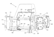
- the vertical seal unit 10 includes a cover 40 covering a pair of heated sealing jaws 21 (heated portions), a position where the cover 40 covers the heated portions, and a position where the cover 40 is exposed.
- a link mechanism 50 that translates between them and an operating rod 60 that rotates the link mechanism 50 in conjunction with the rotation of the vertical seal unit 10 are provided.
- FIG. 8 shows an enlarged side view of the cover 40 and the link mechanism 50
- FIG. 9 shows a state in which the cover 40 attached to the link mechanism 50 via the hinge 42 is flipped up in a direction away from the seal jaw 21.
- a partial perspective view is shown.
- the cover 40 is formed of a plate having a size that covers the entire surface of the sealing jaw 21 to be heated.
- the link mechanism 50 is a parallel link of a so-called four-bar rotation chain, and the fixed-side rotation shafts 51a and 52a of the levers 51 and 52 are rotatably attached to brackets 53 fixed to the attachment plate 18, respectively.
- the swing-side rotation shafts 51b and 52b of the levers 51 and 52 are similarly rotatably attached to the bracket 41 attached to the back side of the cover 40.
- the one lever 51 extends to the opposite side beyond the fixed-side rotating shaft 51a and is a swing end 54 that swings in the opposite direction to the cover 40.
- One end is attached via a rod end bearing 61.
- the other end of the operating rod 60 is also attached to the fixed block 13 of the apparatus side portion 8 via a rod end bearing 62. Therefore, when the vertical seal unit 10 is rotated in the horizontal direction and the operating rod 60 is pulled in the opposite direction, the swinging end 54 of the lever 51 is rotated in the counterclockwise direction. And move to a position where the pair of sealing jaws 21 are covered.
- the cover 40 is retracted to the side of the seal jaw 21 as shown in FIG. is doing. From this state, the lever handle 22 is turned to release the lock with the plate 25, and then the lever handle 22 is pulled forward to rotate the vertical seal unit 10 to the device side portion 8, in conjunction with the movement, The cover 40 located on the side of the seal jaw 21 is pulled by the operating rod 60 and moved to a position covering the seal jaw 21 as shown in FIG. Then, as shown in FIG. 7, when the vertical seal unit 10 is opened to 90 degrees, the cover 40 reaches a position where it completely covers the heated portion of the seal jaw 21. The length of each link of the link mechanism 50, the length of the operating rod 60, and their attachment positions are determined so that such movement and positional relationship can be taken.
- a bracket 41 connected to each of the two levers 51 and 52 arranged on the left and right is arranged on the back side of the cover 40, and the cover 40 is attached to the bracket 41 via a hinge 42. Yes. Therefore, since the cover 40 is connected to the swinging end of the link mechanism 50 via the hinge 42 and the bracket 41, the cover 40 is manually held even when the cover 40 is in a position where it covers the sealing jaw 21 during maintenance. If it is flipped up, the seal jaw 21 can be exposed. Thereby, without removing the cover 40, the alignment of the pair of seal jaws 21 can be adjusted, or the meshing surfaces of the seal jaws 21 can be cleaned to prevent a sealing failure.
- the hinge 42 includes a return spring (not shown).
- the link mechanism 50 is provided on the side where the air cylinder 27 is not disposed, there is nothing to obstruct the parallel movement of the cover 40, and even when the vertical seal unit 10 is set at the vertical seal position of the apparatus body, There is no interference with the tubular film TF. Therefore, it becomes easy to incorporate a safety device including the cover 40, the link mechanism 50, and the operating rod 60 into the existing vertical seal unit.
- the vertical seal unit is rotated in the horizontal direction.
- the vertical seal unit may be configured to be translated through a link.
- a vertical seal unit a system in which a pair of seal jaws 21 sandwiches a seam of a tubular film is employed, but instead of this, a vertical traveling type heating belt as shown in FIG. 10 is mounted. It may be a seal unit. In this case, since the air cylinder for bringing the pair of seal jaws close to and away from each other is not necessary, the vertical seal unit 10 can have a simple structure.
- the inner heater part around which the heating belt circulates is also exposed to the operator side, so the cover is not a plate, but a dome type or a tunnel type, which draws an arc. However, it is configured to cover the heating belt widely.
Landscapes
- Engineering & Computer Science (AREA)
- Mechanical Engineering (AREA)
- Package Closures (AREA)
- Containers And Plastic Fillers For Packaging (AREA)
Abstract
Description
また、リンク機構は、平行リンクで構成され、カバーは、前記平行リンクの揺動端に取り付けられていることが好ましい。この場合には、平行リンクが揺動すると、カバーは、縦シールユニットの加熱部分を被う位置とそれを露出させる位置との間で平行移動する。
なお、舌片26が引っ掛かるプレート25は、ヒンジ11とは反対側の装置側部8に配置された平行シャフト12の先端部に上下に架け渡されている。
8 装置側部
10 縦シールユニット
21 シールジョー(加熱部分)
27 エアーシリンダ(駆動部)
40 カバー
42 蝶番
50 リンク機構
51 一方のレバー
51a 回転軸
54 揺動端
60 作動棹
100 包装装置
Claims (6)
- チューブ状フイルムの縦シール位置から退避可能に設けられた縦シールユニットと、
前記縦シールユニットの加熱部分を被う移動可能なカバーと、
前記縦シールユニットの退避運動を前記カバーに伝達して、前記カバーを、前記加熱部分を露出させた位置からそれを被う位置まで移動させるリンク機構と、
を備えたことを特徴とする包装装置。 - 前記縦シールユニットは、装置側部に水平方向に回動可能に取り付けられ、前記リンク機構は、平行リンクで構成され、
前記カバーは、前記平行リンクの揺動端に取り付けられている、
ことを特徴とする請求項1に記載の包装装置。 - 前記平行リンクを構成する一方のレバーは、前記レバーを回動させる回転軸からさらに伸びて前記カバーとは反対方向に搖動する揺動端を備え、前記揺動端と前記装置側部との間には作動棹が連結され、
前記縦シールユニットが前記装置側部へ回動すると、前記作動棹が、その回動運動を前記レバーに伝達して前記レバーを回動させる、
ことを特徴とする請求項2に記載の包装装置。 - 前記カバーは、蝶番を介して前記リンク機構に連結され、
前記蝶番は、前記加熱部分を前記カバーで被う姿勢と、前記カバーをそこから跳ね上げて前記加熱部分を露出させる姿勢とに切り替え可能である、
ことを特徴とする請求項1から3の何れかに記載の包装装置。 - 前記蝶番は、前記加熱部分から跳ね上げられた前記カバーを元の位置に戻すスプリングを備えている、
ことを特徴とする請求項4に記載の包装装置。 - 前記縦シールユニットは、近接離反する一対のシールジョーを備え、
前記シールジョーの一方の側部には、前記シールジョーを近接離反させる駆動部が配置され、他方の側部には、前記リンク機構が配置されている、
ことを特徴とする請求項1又は2の何れかに記載の包装装置。
Priority Applications (4)
| Application Number | Priority Date | Filing Date | Title |
|---|---|---|---|
| CN201780023415.2A CN109071056B (zh) | 2016-04-28 | 2017-03-06 | 包装装置 |
| AU2017257034A AU2017257034B2 (en) | 2016-04-28 | 2017-03-06 | Packaging machine |
| EP17789077.9A EP3450335B1 (en) | 2016-04-28 | 2017-03-06 | Packaging device |
| US16/095,684 US10988272B2 (en) | 2016-04-28 | 2017-03-06 | Packaging machine |
Applications Claiming Priority (2)
| Application Number | Priority Date | Filing Date | Title |
|---|---|---|---|
| JP2016-090442 | 2016-04-28 | ||
| JP2016090442A JP6742625B2 (ja) | 2016-04-28 | 2016-04-28 | 包装装置 |
Publications (1)
| Publication Number | Publication Date |
|---|---|
| WO2017187788A1 true WO2017187788A1 (ja) | 2017-11-02 |
Family
ID=60161380
Family Applications (1)
| Application Number | Title | Priority Date | Filing Date |
|---|---|---|---|
| PCT/JP2017/008673 Ceased WO2017187788A1 (ja) | 2016-04-28 | 2017-03-06 | 包装装置 |
Country Status (6)
| Country | Link |
|---|---|
| US (1) | US10988272B2 (ja) |
| EP (1) | EP3450335B1 (ja) |
| JP (1) | JP6742625B2 (ja) |
| CN (1) | CN109071056B (ja) |
| AU (1) | AU2017257034B2 (ja) |
| WO (1) | WO2017187788A1 (ja) |
Families Citing this family (11)
| Publication number | Priority date | Publication date | Assignee | Title |
|---|---|---|---|---|
| DE102017128363A1 (de) * | 2017-11-30 | 2019-06-06 | Multivac Sepp Haggenmüller Se & Co. Kg | Verpackungsmaschine mit aufklappbarer schutzabdeckung |
| JP7324489B2 (ja) * | 2019-06-04 | 2023-08-10 | 株式会社川島製作所 | 縦型製袋充填包装機における縦シール装置 |
| JP7294652B2 (ja) * | 2019-08-14 | 2023-06-20 | 株式会社川島製作所 | 薄型モニタを備える正面カバー付き縦型製袋充填包装機 |
| CN110394764B (zh) * | 2019-09-02 | 2021-02-09 | 重庆齿轮箱有限责任公司 | 一种密封件无损拆卸工装 |
| JP7316658B2 (ja) * | 2019-11-25 | 2023-07-28 | 株式会社川島製作所 | 縦型製袋充填包装機及びシャフトの交換方法 |
| JP7449755B2 (ja) * | 2020-03-31 | 2024-03-14 | 株式会社東京自働機械製作所 | 製袋充填機のシール装置 |
| DE102021125155A1 (de) * | 2021-09-28 | 2023-03-30 | Syntegon Technology Gmbh | Siegelvorrichtung und Längssiegeleinrichtung mit einer solchen Siegelvorrichtung |
| CN113928625B (zh) * | 2021-11-01 | 2023-09-15 | 江苏宏芯亿泰智能装备有限公司 | 贴膜设备 |
| CN114199463B (zh) * | 2021-11-16 | 2024-06-11 | 山西欣德易新材料科技有限公司 | 高效干湿分离包装袋的检测装置与方法 |
| JP2024082383A (ja) * | 2022-12-08 | 2024-06-20 | 株式会社イシダ | 製袋包装装置 |
| CN118753602B (zh) * | 2024-09-05 | 2024-11-15 | 四川科斯特自动化设备有限公司 | 一种具有超声波封口的连续式包装机 |
Citations (3)
| Publication number | Priority date | Publication date | Assignee | Title |
|---|---|---|---|---|
| JP2005112374A (ja) * | 2003-10-06 | 2005-04-28 | Tosei Denki Kk | 加熱封止包装機、及び加熱封止包装方法 |
| JP2008018997A (ja) * | 2006-07-14 | 2008-01-31 | Kawashima Packaging Mach Ltd | 製袋包装機 |
| US20120198799A1 (en) * | 2011-02-04 | 2012-08-09 | Ishida Co., Ltd. | Form-fill-seal machine |
Family Cites Families (24)
| Publication number | Priority date | Publication date | Assignee | Title |
|---|---|---|---|---|
| US2934390A (en) * | 1958-11-25 | 1960-04-26 | Walter P Wright | Cabinet with built-in garbage receptacle |
| SE310618B (ja) * | 1963-05-20 | 1969-05-05 | Akerlund & Rausing Ab | |
| JPH0820842B2 (ja) * | 1987-12-14 | 1996-03-04 | キヤノン株式会社 | プロセスカートリッジ及び画像形成装置 |
| US4996825A (en) * | 1989-01-31 | 1991-03-05 | Kliklok Corporation | Combined blousing, stripping and sealing for bag forming and method |
| US4909017B1 (en) * | 1989-07-28 | 1999-02-09 | Minigrip Inc | Reclosable bag material method and apparatus |
| JPH04247468A (ja) * | 1991-02-01 | 1992-09-03 | Fuji Xerox Co Ltd | 画像形成装置 |
| DE4313205C1 (de) * | 1993-04-22 | 1994-08-18 | Haensel Otto Gmbh | Vertikal taktweise arbeitende Flachbeutelmaschine mit in eine Einricht- und Reinigungsstellung verschwenkbaren Siegeleinheiten |
| JPH07230197A (ja) * | 1994-02-17 | 1995-08-29 | Fuji Xerox Co Ltd | 画像形成装置 |
| DE19541617A1 (de) * | 1995-11-08 | 1997-05-15 | Bosch Gmbh Robert | Schlauchbeutelmaschine |
| US5852920A (en) * | 1996-11-13 | 1998-12-29 | Triangle Package Machinery Company | Longitudinal seam sealer for continuous motion form, fill and seal machine |
| JP2003291925A (ja) * | 2002-04-08 | 2003-10-15 | Ibaraki Precision Mach Co Ltd | フイルムの溶着装置 |
| AU2003252279B8 (en) | 2002-07-30 | 2009-11-19 | Ishida Co., Ltd. | Packaging Apparatus, Packaging Method, and Packaging System |
| JP2004149213A (ja) * | 2002-10-30 | 2004-05-27 | Yakotekku:Kk | 自動包装機用シール装置 |
| NL1023151C2 (nl) * | 2003-01-06 | 2004-07-07 | C F S Weert B V | Inrichting en werkwijze voor het vervaardigen van hersluitbare verpakkingen. |
| CN101166666B (zh) * | 2005-05-31 | 2010-05-26 | 株式会社汤山制作所 | 药品分包装置 |
| WO2007106916A1 (en) * | 2006-03-15 | 2007-09-20 | August Egli | Continuous motion vertical form, fill and seal machine |
| JP5725897B2 (ja) * | 2011-02-16 | 2015-05-27 | 株式会社イシダ | 包装機 |
| US10076207B2 (en) * | 2011-03-25 | 2018-09-18 | Ping-Hua CHANG | Automatic cooking apparatus |
| AU2012201594B2 (en) * | 2011-04-11 | 2016-06-23 | Tna Australia Pty Limited | A bag seal inspection device |
| DE102011075379A1 (de) * | 2011-05-06 | 2012-11-08 | Robert Bosch Gmbh | Schlauchbeutelmaschine und Verfahren zum Betreiben einer Schlauchbeutelmaschine |
| US9617053B2 (en) * | 2012-06-28 | 2017-04-11 | Koninklijke Douwe Egberts B.V. | Reclosable flexible packages for food products |
| CN102717907B (zh) * | 2012-07-16 | 2015-04-29 | 上海松川远亿机械设备有限公司 | 立式包装机 |
| CN202765346U (zh) * | 2012-09-20 | 2013-03-06 | 佛山市德亦宝机械制造有限公司 | 一种连续包装机的纵封机构 |
| ES1135355Y (es) * | 2014-12-18 | 2015-04-13 | Ulma Packaging Technological Ct S Coop | Máquina de envasado vertical |
-
2016
- 2016-04-28 JP JP2016090442A patent/JP6742625B2/ja active Active
-
2017
- 2017-03-06 CN CN201780023415.2A patent/CN109071056B/zh active Active
- 2017-03-06 EP EP17789077.9A patent/EP3450335B1/en active Active
- 2017-03-06 WO PCT/JP2017/008673 patent/WO2017187788A1/ja not_active Ceased
- 2017-03-06 US US16/095,684 patent/US10988272B2/en active Active
- 2017-03-06 AU AU2017257034A patent/AU2017257034B2/en active Active
Patent Citations (3)
| Publication number | Priority date | Publication date | Assignee | Title |
|---|---|---|---|---|
| JP2005112374A (ja) * | 2003-10-06 | 2005-04-28 | Tosei Denki Kk | 加熱封止包装機、及び加熱封止包装方法 |
| JP2008018997A (ja) * | 2006-07-14 | 2008-01-31 | Kawashima Packaging Mach Ltd | 製袋包装機 |
| US20120198799A1 (en) * | 2011-02-04 | 2012-08-09 | Ishida Co., Ltd. | Form-fill-seal machine |
Also Published As
| Publication number | Publication date |
|---|---|
| AU2017257034A1 (en) | 2018-11-29 |
| EP3450335B1 (en) | 2020-01-22 |
| JP2017197238A (ja) | 2017-11-02 |
| EP3450335A1 (en) | 2019-03-06 |
| EP3450335A4 (en) | 2019-03-13 |
| AU2017257034B2 (en) | 2019-07-04 |
| CN109071056A (zh) | 2018-12-21 |
| US10988272B2 (en) | 2021-04-27 |
| CN109071056B (zh) | 2020-06-16 |
| JP6742625B2 (ja) | 2020-08-19 |
| US20190152638A1 (en) | 2019-05-23 |
Similar Documents
| Publication | Publication Date | Title |
|---|---|---|
| WO2017187788A1 (ja) | 包装装置 | |
| JP2017197238A5 (ja) | ||
| JP6239957B2 (ja) | 製袋包装機および製袋包装システム | |
| JP2012224442A (ja) | 横型製袋充填包装機の供給コンベヤ | |
| JP5908974B2 (ja) | 製袋包装機 | |
| JP2014009028A (ja) | ヒートシール金具タイプ自動包装機 | |
| JP5658855B2 (ja) | ヒータブロックの清掃容易な横型包装機 | |
| JP2020189670A (ja) | ピロー包装機 | |
| JP6970420B2 (ja) | トグル機構作動式のシールユニットを備えた包装機 | |
| US3412525A (en) | Apparatus for wrapping objects | |
| JP7070878B2 (ja) | ベルト隙間設定機能を備えた製袋充填包装機 | |
| JP2006193176A (ja) | 製袋包装機 | |
| JP4875877B2 (ja) | ヘム付き袋製袋装置 | |
| JP5291540B2 (ja) | 製袋包装機 | |
| JP2005053547A (ja) | 縦型充填包装機用のシーリング装置とこれを用いた充填包装機 | |
| JP2019023094A (ja) | シール装置とそれを使用した包装装置 | |
| JP7449755B2 (ja) | 製袋充填機のシール装置 | |
| JP5102586B2 (ja) | 自動包装機 | |
| US20080163589A1 (en) | Combined packaging machine | |
| JP6498948B2 (ja) | 縦形製袋充填包装機の縦シール装置 | |
| JP4933180B2 (ja) | 製袋包装機 | |
| IT202100029807A1 (it) | Apparato per la realizzazione di contenitori riempiti di un liquido e sigillati. | |
| US11230064B2 (en) | Inspection of a vertical flow-wrapper | |
| JPH09150807A (ja) | 製袋装置における底シール装置 | |
| JP7444649B2 (ja) | 製袋充填機の縦シール装置 |
Legal Events
| Date | Code | Title | Description |
|---|---|---|---|
| NENP | Non-entry into the national phase |
Ref country code: DE |
|
| 121 | Ep: the epo has been informed by wipo that ep was designated in this application |
Ref document number: 17789077 Country of ref document: EP Kind code of ref document: A1 |
|
| WWE | Wipo information: entry into national phase |
Ref document number: 2017789077 Country of ref document: EP |
|
| ENP | Entry into the national phase |
Ref document number: 2017257034 Country of ref document: AU Date of ref document: 20170306 Kind code of ref document: A |
|
| ENP | Entry into the national phase |
Ref document number: 2017789077 Country of ref document: EP Effective date: 20181128 |