WO2017187821A1 - 情報処理装置及び情報処理方法、並びに3次元画像データの伝送方法 - Google Patents
情報処理装置及び情報処理方法、並びに3次元画像データの伝送方法 Download PDFInfo
- Publication number
- WO2017187821A1 WO2017187821A1 PCT/JP2017/010034 JP2017010034W WO2017187821A1 WO 2017187821 A1 WO2017187821 A1 WO 2017187821A1 JP 2017010034 W JP2017010034 W JP 2017010034W WO 2017187821 A1 WO2017187821 A1 WO 2017187821A1
- Authority
- WO
- WIPO (PCT)
- Prior art keywords
- video
- information processing
- dimensional image
- image
- control unit
- Prior art date
- Legal status (The legal status is an assumption and is not a legal conclusion. Google has not performed a legal analysis and makes no representation as to the accuracy of the status listed.)
- Ceased
Links
Images






Classifications
-
- H—ELECTRICITY
- H04—ELECTRIC COMMUNICATION TECHNIQUE
- H04N—PICTORIAL COMMUNICATION, e.g. TELEVISION
- H04N13/00—Stereoscopic video systems; Multi-view video systems; Details thereof
- H04N13/10—Processing, recording or transmission of stereoscopic or multi-view image signals
- H04N13/194—Transmission of image signals
-
- G—PHYSICS
- G06—COMPUTING OR CALCULATING; COUNTING
- G06T—IMAGE DATA PROCESSING OR GENERATION, IN GENERAL
- G06T17/00—Three-dimensional [3D] modelling for computer graphics
- G06T17/10—Constructive solid geometry [CSG] using solid primitives, e.g. cylinders, cubes
-
- G—PHYSICS
- G06—COMPUTING OR CALCULATING; COUNTING
- G06T—IMAGE DATA PROCESSING OR GENERATION, IN GENERAL
- G06T19/00—Manipulating three-dimensional [3D] models or images for computer graphics
-
- G—PHYSICS
- G06—COMPUTING OR CALCULATING; COUNTING
- G06T—IMAGE DATA PROCESSING OR GENERATION, IN GENERAL
- G06T3/00—Geometric image transformations in the plane of the image
-
- G—PHYSICS
- G06—COMPUTING OR CALCULATING; COUNTING
- G06T—IMAGE DATA PROCESSING OR GENERATION, IN GENERAL
- G06T3/00—Geometric image transformations in the plane of the image
- G06T3/16—Spatio-temporal transformations, e.g. video cubism
-
- H—ELECTRICITY
- H04—ELECTRIC COMMUNICATION TECHNIQUE
- H04N—PICTORIAL COMMUNICATION, e.g. TELEVISION
- H04N13/00—Stereoscopic video systems; Multi-view video systems; Details thereof
- H04N13/10—Processing, recording or transmission of stereoscopic or multi-view image signals
- H04N13/106—Processing image signals
- H04N13/111—Transformation of image signals corresponding to virtual viewpoints, e.g. spatial image interpolation
-
- H—ELECTRICITY
- H04—ELECTRIC COMMUNICATION TECHNIQUE
- H04N—PICTORIAL COMMUNICATION, e.g. TELEVISION
- H04N13/00—Stereoscopic video systems; Multi-view video systems; Details thereof
- H04N13/10—Processing, recording or transmission of stereoscopic or multi-view image signals
- H04N13/106—Processing image signals
- H04N13/167—Synchronising or controlling image signals
-
- H—ELECTRICITY
- H04—ELECTRIC COMMUNICATION TECHNIQUE
- H04N—PICTORIAL COMMUNICATION, e.g. TELEVISION
- H04N13/00—Stereoscopic video systems; Multi-view video systems; Details thereof
- H04N13/10—Processing, recording or transmission of stereoscopic or multi-view image signals
- H04N13/106—Processing image signals
- H04N13/172—Processing image signals image signals comprising non-image signal components, e.g. headers or format information
-
- H—ELECTRICITY
- H04—ELECTRIC COMMUNICATION TECHNIQUE
- H04N—PICTORIAL COMMUNICATION, e.g. TELEVISION
- H04N21/00—Selective content distribution, e.g. interactive television or video on demand [VOD]
- H04N21/20—Servers specifically adapted for the distribution of content, e.g. VOD servers; Operations thereof
- H04N21/21—Server components or server architectures
- H04N21/218—Source of audio or video content, e.g. local disk arrays
-
- H—ELECTRICITY
- H04—ELECTRIC COMMUNICATION TECHNIQUE
- H04N—PICTORIAL COMMUNICATION, e.g. TELEVISION
- H04N21/00—Selective content distribution, e.g. interactive television or video on demand [VOD]
- H04N21/20—Servers specifically adapted for the distribution of content, e.g. VOD servers; Operations thereof
- H04N21/23—Processing of content or additional data; Elementary server operations; Server middleware
- H04N21/234—Processing of video elementary streams, e.g. splicing of video streams or manipulating encoded video stream scene graphs
- H04N21/2343—Processing of video elementary streams, e.g. splicing of video streams or manipulating encoded video stream scene graphs involving reformatting operations of video signals for distribution or compliance with end-user requests or end-user device requirements
-
- H—ELECTRICITY
- H04—ELECTRIC COMMUNICATION TECHNIQUE
- H04N—PICTORIAL COMMUNICATION, e.g. TELEVISION
- H04N21/00—Selective content distribution, e.g. interactive television or video on demand [VOD]
- H04N21/40—Client devices specifically adapted for the reception of or interaction with content, e.g. set-top-box [STB]; Operations thereof
- H04N21/41—Structure of client; Structure of client peripherals
- H04N21/422—Input-only peripherals, i.e. input devices connected to specially adapted client devices, e.g. global positioning system [GPS]
- H04N21/42201—Input-only peripherals, i.e. input devices connected to specially adapted client devices, e.g. global positioning system [GPS] biosensors, e.g. heat sensor for presence detection, EEG sensors or any limb activity sensors worn by the user
-
- H—ELECTRICITY
- H04—ELECTRIC COMMUNICATION TECHNIQUE
- H04N—PICTORIAL COMMUNICATION, e.g. TELEVISION
- H04N21/00—Selective content distribution, e.g. interactive television or video on demand [VOD]
- H04N21/40—Client devices specifically adapted for the reception of or interaction with content, e.g. set-top-box [STB]; Operations thereof
- H04N21/41—Structure of client; Structure of client peripherals
- H04N21/422—Input-only peripherals, i.e. input devices connected to specially adapted client devices, e.g. global positioning system [GPS]
- H04N21/4223—Cameras
-
- H—ELECTRICITY
- H04—ELECTRIC COMMUNICATION TECHNIQUE
- H04N—PICTORIAL COMMUNICATION, e.g. TELEVISION
- H04N21/00—Selective content distribution, e.g. interactive television or video on demand [VOD]
- H04N21/80—Generation or processing of content or additional data by content creator independently of the distribution process; Content per se
- H04N21/81—Monomedia components thereof
- H04N21/816—Monomedia components thereof involving special video data, e.g 3D video
-
- H—ELECTRICITY
- H04—ELECTRIC COMMUNICATION TECHNIQUE
- H04N—PICTORIAL COMMUNICATION, e.g. TELEVISION
- H04N23/00—Cameras or camera modules comprising electronic image sensors; Control thereof
- H04N23/60—Control of cameras or camera modules
- H04N23/698—Control of cameras or camera modules for achieving an enlarged field of view, e.g. panoramic image capture
-
- H—ELECTRICITY
- H04—ELECTRIC COMMUNICATION TECHNIQUE
- H04N—PICTORIAL COMMUNICATION, e.g. TELEVISION
- H04N21/00—Selective content distribution, e.g. interactive television or video on demand [VOD]
- H04N21/20—Servers specifically adapted for the distribution of content, e.g. VOD servers; Operations thereof
- H04N21/21—Server components or server architectures
- H04N21/218—Source of audio or video content, e.g. local disk arrays
- H04N21/2187—Live feed
Definitions
- the technology disclosed in the present specification relates to an information processing apparatus, an information processing method, and a transmission method for encoding video information, and in particular, an information processing apparatus that performs mapping processing of all-around video for encoding compression and
- the present invention relates to an information processing method and a transmission method of three-dimensional image data.
- a first database that stores three-dimensional shape data of real estate properties and a second database that stores interior information of real estate properties as three-dimensional shape data are arranged so as to be viewable via the Internet.
- a real estate property sales support system that displays the inside of a real estate property as a virtual space based on the three-dimensional shape data read from the second database has been proposed (for example, see Patent Document 1).
- the interior of the living space based on the three-dimensional shape data of the living space and the three-dimensional shape data of the interior information of the living space can be displayed as a virtual space to the purchaser of the property.
- An object of the technology disclosed in the present specification is to provide an excellent information processing apparatus and information processing method, and a three-dimensional image data transmission method capable of suitably performing the all-sky video mapping process. .
- a receiving unit for receiving a three-dimensional image A storage unit that holds a three-dimensional model for mapping the three-dimensional image to a two-dimensional image; A transmission unit for transmitting the two-dimensional image; A control unit; Comprising The control unit determines a three-dimensional model to be used based on an instruction from a user or a surrounding environment, maps the three-dimensional image to a two-dimensional image based on the determined three-dimensional model, and the two-dimensional image Is transmitted from the transmitter.
- Information processing apparatus is
- the reception unit of the information processing device receives a panoramic image as the three-dimensional image
- the shape for mapping the whole sky image is configured to be switched and controlled among a plurality of three-dimensional models including at least one of the shape of a cylinder, a cube, a quadrangular pyramid, and a subject.
- the reception unit of the information processing device receives a first signal from a first device that captures the whole sky video.
- the control unit is configured to perform the switching control based on information included in the first signal.
- control unit of the information processing apparatus performs the switching control according to a user instruction included in the first signal. It is configured as follows.
- control unit of the information processing device performs the operation according to information indicating a situation at the time of imaging included in the first signal. It is configured to perform switching control.
- control unit of the information processing device provides the bottom surface of the subject based on the subject information included in the first signal. It is configured to switch to mapping using a quadrangular pyramid.
- the transmission unit of the information processing device transmits the two-dimensional image in which the all-sky image is mapped to a second device.
- the said control part is comprised so that the said switching control may be performed based on the information contained in the 2nd signal received from the said 2nd apparatus.
- control unit of the information processing device performs the switching control based on information on a subject included in the second signal. It is configured as follows.
- control unit of the information processing device is configured to switch to mapping using a quadrangular pyramid with a bottom surface facing the subject. ing.
- control unit of the information processing device has a bottom surface in the direction of the line of sight based on the line-of-sight information included in the second signal. It is configured to switch to mapping using a quadrangular pyramid.
- control unit of the information processing device performs the switching control according to a user instruction included in the second signal. It is configured as follows.
- the transmission unit of the information processing device is a transmission unit that transmits the whole sky video to a plurality of second devices, and
- the control unit is configured to perform the switching control based on line-of-sight information included in the second signal received from each of the plurality of second devices.
- control unit of the information processing device has a bottom surface in the direction of each line of sight with respect to the plurality of second devices.
- Each of the two-dimensional images mapped by using the directed quadrangular pyramids is unicasted.
- control unit of the information processing device performs mapping using a quadrangular pyramid with a bottom surface directed to a region including most of the line of sight.
- a two-dimensional image is configured to be transmitted by multicast transmission.
- the information processing apparatus further includes a monitoring unit that monitors a state of a transmission path that transmits the all-sky video.
- the said control part is comprised so that the said switching control may be performed based on the condition of the said transmission line.
- control unit of the information processing device includes a transmission including information for specifying the three-dimensional model used for the mapping.
- the two-dimensional image is transmitted from the transmission unit in a format.
- the seventeenth aspect of the technology disclosed in this specification is: A receiving step for receiving a three-dimensional image; A storage step of storing in the storage unit a three-dimensional model for mapping the three-dimensional image to a two-dimensional image; A transmitting step of transmitting the two-dimensional image; Control steps; Have In the control step, a three-dimensional model to be used is determined based on an instruction from a user or a surrounding environment, the three-dimensional image is mapped to a two-dimensional image based on the determined three-dimensional model, and the two-dimensional image Is an information processing method for transmitting in the transmission step.
- An eighteenth aspect of the technology disclosed in this specification is a method of transmitting three-dimensional image data, Two-dimensional map image data in which the three-dimensional image is mapped to a two-dimensional image based on the three-dimensional model and ancillary data for specifying the three-dimensional model used for the mapping are made into one data set. Steps, Transmitting the data set; Is a method for transmitting three-dimensional image data.
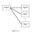
- FIG. 1 is a diagram schematically illustrating a configuration example of a video viewing system 100 for viewing video.
- FIG. 2 is a diagram schematically illustrating a configuration example of a video viewing system 200 for viewing video.
- FIG. 3 is a diagram schematically illustrating a configuration example of a video viewing system 300 for viewing a video.
- FIG. 4 is a diagram schematically illustrating a configuration example of a video viewing system 400 for viewing video.
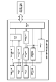
- FIG. 5 is a diagram schematically illustrating a functional configuration of an information processing apparatus 500 that can function as a video providing apparatus.
- FIG. 6 is a diagram schematically illustrating a functional configuration of an information processing apparatus 600 that can function as a video reproduction apparatus.
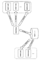
- FIG. 7 is a diagram for explaining a mechanism for viewing archived video.
- FIG. 1 is a diagram schematically illustrating a configuration example of a video viewing system 100 for viewing video.
- FIG. 2 is a diagram schematically illustrating a configuration example of a video viewing system 200 for viewing video.
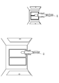
- FIG. 8 is a diagram showing an example in which the video viewing system 100 is applied to an appearance of a real estate property.
- FIG. 9 is a diagram showing an example in which the video viewing system 100 is applied to an appearance of a real estate property.
- FIG. 10 is a diagram for explaining a cylindrical projection method in which an all-sky image is projected onto a cylinder and developed on a plane.
- FIG. 11 is a diagram for explaining a mapping method in which a spherical all-sky image is projected onto a cube and developed on a plane.
- FIG. 12 is a diagram for explaining a mapping method in which a spherical all-sky image is projected onto a quadrangular pyramid and developed on a plane.
- FIG. 10 is a diagram for explaining a cylindrical projection method in which an all-sky image is projected onto a cylinder and developed on a plane.
- FIG. 11 is a diagram for explaining a mapping method in which a spherical all-sky image is projected onto a cu
- FIG. 13 is a diagram for explaining a mapping method in which a spherical all-sky image is projected onto a quadrangular pyramid and developed on a plane.
- FIG. 14 is a diagram for explaining a mapping method in which a spherical all-sky image is projected onto a quadrangular pyramid and developed on a plane.
- FIG. 15 is a diagram illustrating an example of mapping the entire sky image on the surface of an object having an arbitrary shape.
- FIG. 16 is a diagram for explaining a method of mapping the whole sky video according to the situation.
- FIG. 17 is a diagram for explaining a method of mapping the whole sky video according to the situation.
- FIG. 18 is a diagram for explaining a method of mapping the whole sky video according to the situation.
- FIG. 19 is a diagram for explaining a method of mapping an all-around video according to a situation.
- FIG. 20 is a diagram for explaining a method of mapping the whole sky video according to the situation.
- FIG. 21 is a flowchart illustrating a schematic processing procedure for dynamically and legally switching the mapping method of the all-sky video.
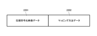
- FIG. 22 is a diagram showing an example of a transmission format of compression-encoded all-around video.
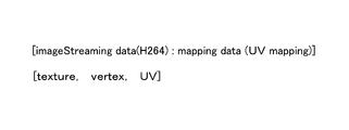
- FIG. 23 is a diagram illustrating a syntax example of compression-encoded all-sky video.
- FIG. 1 schematically shows a configuration example of a video viewing system 100 for viewing video.
- the video viewing system 100 includes one video providing device 101 that provides video and one video playback device 102 that plays back video, and constitutes a one-to-one network topology.
- the video providing apparatus 101 and the video reproduction apparatus 102 are interconnected via a wide area network such as a wireless or wired LAN (Local Area Network) or the Internet, for example.
- a wide area network such as a wireless or wired LAN (Local Area Network) or the Internet, for example.
- LAN Local Area Network
- the video providing apparatus 101 is an information terminal operated by, for example, a user (property of a property or a salesman of a real estate company) in a real estate property (local site).
- the video providing apparatus 101 may be a fixed-point camera installed on the site or a camera mounted on a robot that operates autonomously on site.
- the video playback device 102 does not go to the local area, but considers a user (such as a real estate company store or home) who browses property information (for example, a real estate purchase or rental contract).
- Information terminal operated by a customer operated by a customer).
- the video providing apparatus 101 includes an imaging unit that captures a video (for example, a viewpoint video of a salesman located in a real estate property) having the installation position of the video providing apparatus 101 as a viewpoint, and the video playback apparatus 102 displays the captured video.
- a video for example, a viewpoint video of a salesman located in a real estate property
- the video playback apparatus 102 displays the captured video.
- the imaging unit may be configured with one omnidirectional camera. However, even if it is an all-round image, it is not necessary to be 360 degrees, and a part of the visual field may be missing (the same applies hereinafter).
- the video providing apparatus 101 further includes an audio input unit such as a microphone, and multiplexes the audio collected from the imaging scene of the whole sky video with the video and transmits the multiplexed audio to the video playback apparatus 102. Also good. For example, a salesman located in a real estate property may collect voices explaining the location conditions and floor plans of the property and transmit them to the video playback device 102.
- an audio input unit such as a microphone
- the video providing apparatus 101 may include a display unit.
- the display unit (or video providing apparatus 101 itself) is configured as a transmissive head-mounted display, for example. Users in the local area wear this head-mounted display on their heads, and perform local shooting and explanation of the property while referring to the images displayed on the head-mounted display as seen through.
- One video playback device 102 includes a display unit that displays the video received from the video providing device 101.
- the video playback device 102 (or its display unit) is configured as, for example, a head-mounted display that a user wears on the head and views video.
- the video reproduction device 102 cuts out and displays a predetermined angle of view from the all-sky video (video obtained by imaging the room of the real estate property) captured by the video providing device 101.
- the video playback device 102 may be configured as a dome-type display, and may display all the sky images captured at the place where the video providing device 101 is installed.
- the video playback device 102 may be a normal (or large screen) monitor display.
- the video playback device 102 includes an audio output unit such as a speaker or a headphone, and the audio transmitted from the video providing device 101 in a multiplexed manner with the video (for example, a salesman in the local area of a real estate property determines the location conditions of the property Or audio explaining the floor plan) may be reproduced and output together with the video.
- an audio output unit such as a speaker or a headphone
- the video reproduction device 102 may further include a voice input unit such as a microphone, and may input a voice instruction from the user.
- a voice instruction such as “I want to see the view on the veranda” or “Show my living room”, and such an instruction is transmitted to the video providing device 101.
- the video providing apparatus 101 once transmits the all-sky image captured at the site to the distribution server 103.
- the distribution server 103 transmits to the video playback device 102 all-round video or video for a predetermined angle of view cut out from the full-sky video.
- the distribution server 103 also archives video received from the video providing apparatus 101.
- one video providing apparatus 101 and one video playback apparatus 102 constitute a one-to-one network topology.
- this corresponds to an embodiment in which a video captured by one video providing apparatus 101 installed in a specific property is viewed between one video playback apparatus 102 installed in a real estate store.
- Customers can view the real video of the property in a form that is close to the actual feeling without visiting the local area, so that an efficient look can be achieved and customer satisfaction is improved.
- FIGS. 2 to 4 show modified examples of the video viewing system 100 for viewing the whole sky video.
- the distribution server is omitted, but it should be understood that the distribution server is interposed between the video providing apparatus and the video reproduction apparatus in any case.
- the video viewing system 200 shown in FIG. 2 has a one-to-N network topology with one video providing device 201 and a plurality (N) of video playback devices 202-1, 202-2,. All-round images captured by one image providing apparatus 201 (the same image captured at the same viewpoint position and in the same line of sight) are respectively reproduced by the image reproducing apparatuses 202-1, 202-2,. It is designed to watch at 202-N at the same time.
- an image of a property imaged by one image providing device 201 installed in a specific property is installed in a plurality of units installed in a real estate store (or installed in a plurality of branches of a real estate company). This corresponds to an embodiment of viewing with the video playback devices 202-1, 202-2,..., 202-N. Since a plurality of customers can share and view a real video of one property, an efficient preview can be realized for a real estate company.
- FIG. 3 includes a plurality of (N) video providing apparatuses 301-1, 301-2,..., 301-N and one video reproducing apparatus 302, which is an N-to-1 network network. Topology is configured, and one video playback device 302 selectively receives video from any one of video providing devices 301-1, 301-2, ..., 301-N installed at different locations. It is to be displayed. Assume that the video reproduction device 302 can dynamically switch the video transmission source among the video providing devices 301-1, 301-2,..., 301-N.
- the viewpoint position of the video that is played back (viewable) by the video playback device 302 is switched (the viewpoint position is instantaneously changed to the installation location of the selected video providing device 301). Moving). Further, it is assumed that the video reproduction device 302 can instruct the selected video providing device 301 to switch the line-of-sight direction.
- one video playback device 302 installed in a real estate store switches videos from a plurality of video providing devices 301-1 301-2, 301-N installed in a plurality of properties, respectively. This corresponds to an embodiment of viewing while viewing.
- an embodiment is also assumed in which videos of a plurality of video providing apparatuses 301-1, 301-2,..., 301-N installed in each real estate property room are viewed while being switched by the video playback apparatus 302. Is done.
- the customer can view the real video of each property at a stroke without having to move around the property at once, so that it can realize an efficient look and improve customer satisfaction.
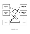
- the N-to-N network topology may include the one-to-one network shown in FIG. 1, the one-to-N network shown in FIG. 2, and the N-to-one network shown in FIG.
- each of a plurality of video playback devices 402-1, 402-2,..., 402-N installed in a real estate store (or installed in each of a plurality of branches of a real estate company) .., 401-N are viewed while being switched. Since each customer can view the real video of each property at a stroke without having to move around each property, it is possible to achieve an efficient look and improve customer satisfaction.
- FIG. 5 schematically shows a functional configuration of an information processing device 500 that can function as a video providing device in the video viewing systems 100 to 400.
- the illustrated information processing apparatus 500 includes an imaging unit 501, a video encoding unit 503, an audio input unit 504, an audio encoding unit 505, a multiplexing unit (MUX) 506, a communication unit 507, and a video decoding unit. 508, an image processing unit 509, a display unit 510, an audio decoding unit 511, an audio output unit 512, and a control unit 513.
- MUX multiplexing unit
- the imaging unit 501 includes a single-lens camera (including a wide-angle camera and a fish-eye camera), a two-lens stereo camera, a multi-lens all-sky camera, and the like. If a stereo camera is used, a sense of depth can be given to the video.
- the imaging unit 501 images the surroundings with the place where the information processing apparatus 500 is installed as the viewpoint position.
- the video encoding unit 503 performs encoding processing of the video signal captured by the imaging unit 501.
- the audio input unit 504 is configured with, for example, a small microphone, a stereo microphone, and the like, and can be collected together with the imaging unit 501 to collect the sound at the imaging site of the whole sky video. If a stereo microphone is used, the sound at the time of sound collection can be reconstructed three-dimensionally on the playback side (that is, the video playback device).
- the voice encoding unit 505 encodes the voice signal input by the voice input unit 504.
- the multiplexing unit 506 multiplexes the encoded video signal and the encoded audio signal encoded by the video encoding unit 503 and the audio encoding unit 505, respectively, and transmits the signal to the video reproduction apparatus via the distribution server. Form into a format (packet).
- the display unit 510 (or the entire video providing apparatus 500) is configured as a transmissive head-mounted display, for example.
- the display unit 510 (or the entire video providing apparatus 500) is configured as a portable information terminal (with a camera) such as a smartphone or a tablet.
- the display unit 510 superimposes and displays an image on the field of view of the user who images the property on the spot.
- the video decoding unit 508 decodes archive video received from, for example, a distribution server.
- the image processing unit 509 performs processing such as image recognition of the image captured by the imaging unit 501 and the video decoded by the video decoding unit 508, and generates a video to be displayed on the display unit 510.
- the display unit 510 displays guidance information such as a destination and a movement route to the user.
- the audio decoding unit 511 performs a decoding process on an encoded audio signal received from, for example, a video reproduction device.
- the audio output unit 512 outputs the decoded baseband audio signal as audio. For example, a voice instruction such as “I want to see the view on the veranda” or “Show me the living room” from the user of the video playback device is output as voice.
- the communication unit 507 performs mutual communication with the video reproduction device, including transmission of video and audio. However, it is assumed that a distribution server (described above) intervenes in communication with the video reproduction device.
- the communication unit 507 performs mutual communication with a video reproduction device, a distribution server, and other external devices through a wide area network such as a wireless or wired LAN or the Internet, for example.
- the control unit 513 comprehensively controls the operations of the units 501 to 512 described above. For example, the control unit 513 performs processing for realizing real-time communication with a video playback device (or a viewing group) that is a video transmission destination, and the display unit 510 uses a user (thing for photographing a property locally). ) Is displayed. In addition, the control unit 513 turns on / off an imaging operation and an audio input operation in order to limit a range of information to be provided according to attribute information of a video reproduction device (or a viewing group) that is a video transmission destination. Mosaic, mask processing, and input audio modulation processing are performed on the captured video.
- FIG. 6 schematically shows a functional configuration of an information processing device 600 that can function as a video reproducing device in the video viewing systems 100 to 400.
- the illustrated information processing apparatus 600 includes a communication unit 601, a separation unit (DEMUX) 602, an audio decoding unit 603, an audio output unit 604, a video decoding unit 605, a display unit 606, a sound collection unit 607, A voice encoding unit 608, a sensor unit 609, and a control unit 610 are provided.
- DEMUX separation unit
- an audio decoding unit 603 an audio output unit 604
- video decoding unit 605 a display unit 606, a sound collection unit 607
- a voice encoding unit 608, a sensor unit 609, and a control unit 610 are provided.
- each unit 601 to 610 will be described.
- the communication unit 601 performs mutual communication with the video providing apparatus, including transmission of video and audio. Further, communication with the distribution server (described above) is performed via the communication unit 601 as necessary.
- the communication unit 601 performs mutual communication with a video providing device, a distribution server, and other external devices through a wide area network such as a wireless or wired LAN or the Internet.
- a video or audio transmission start request is transmitted from the communication unit 601 to a video providing apparatus installed in a place where a video is desired to be viewed (for example, a real estate property that is desired to be viewed).
- the communication unit 601 receives a transmission signal formed in a predetermined signal format (packet) from the video providing apparatus.
- a video received from a video providing device is being displayed (that is, being viewed by a user) and the user wants to see a different gaze direction at the viewpoint position
- the gaze direction change request is transmitted from the communication unit 601.
- a transmission stop request is transmitted from the communication unit 601 to the video providing device that is receiving the video or audio, and a transmission start request is sent to the destination video providing device. Is transmitted from the communication unit 601.
- the separating unit 602 separates the signal multiplexed and transmitted from the video providing apparatus into an encoded video signal and an encoded audio signal, and distributes them to the audio decoding unit 603 and the video decoding unit 605, respectively.
- the audio decoding unit 603 generates a baseband audio signal by decoding the encoded audio signal, and outputs the audio from the audio output unit 604.
- the audio output unit 604 includes monaural, stereo, multi-channel speakers, and the like.
- the video decoding unit 605 decodes the encoded video signal to generate a baseband video signal, and displays the video captured by the transmission source video providing apparatus on the display unit 606.
- the display unit 606 (or the information processing apparatus 600 main body) is configured by, for example, a head-mounted display, a dome-type display, or a large screen (or normal) monitor display.
- the sound collection unit 607 is constituted by a small microphone or a stereo microphone, for example, and collects a user's voice and the like.
- the audio encoding unit 608 encodes the audio signal input by the sound collection unit 607 and outputs the encoded audio signal to the control unit 610. If the user's voice is an impression or admiration for the video displayed on the display unit 606, or a voice instruction to the control unit 610 (or video playback device) (for example, changing the line-of-sight direction of the all-sky image) There is also.
- the user of the video playback device can give a voice instruction such as “I want to see the view of the veranda” or “Show the living room” while viewing the video of the property of the property that I want to see on the display unit 606. .
- a voice instruction such as “I want to see the view of the veranda” or “Show the living room” while viewing the video of the property of the property that I want to see on the display unit 606.
- Such user's voice is collected by the sound collection unit 607, encoded by the audio encoding unit 608, and then transmitted from the communication unit 601 to the video providing apparatus.
- the control unit 610 controls the output of video and audio received from the video providing device.
- the control unit 610 controls display of UI and OSD (On-Screen Display) on the screen of the display unit 606, and processes operations performed by the user (viewer) on the UI and OSD.
- UI and OSD On-Screen Display
- the sensor unit 609 measures the line-of-sight direction, the head position, or the posture of the user (a viewer who views the video displayed on the screen of the display unit 606).
- the sensor unit 609 is configured by combining a plurality of sensor elements such as a gyro sensor, an acceleration sensor, and a geomagnetic sensor, for example (a total of 9 axes including a 3-axis gyro sensor, a 3-axis acceleration sensor, and a 3-axis geomagnetic sensor can be detected. Sensor).
- the sensor unit 609 may be integrated with the main body of the information processing apparatus 600 (head mount, display, etc.), or may be an accessory part attached to the main body.
- Operations such as the user's line-of-sight direction, head position, or posture detected by the sensor unit 609 (or gesture operations using not only the head but also the torso and limbs) are displayed on the UI displayed on the display unit 609.
- this may mean an instruction of an angle of view to be displayed on the display unit 609 in the whole sky video.
- the horizontal and vertical swinging of the user can be handled as an instruction to change the line-of-sight direction in the all-sky video.
- an operation in which the user tilts the body forward or backward may be handled as a zoom operation of the camera in the current line-of-sight direction (zoom up if tilted forward, zoom down if tilted backward). Then, the detection result of the sensor unit 609 is output to the control unit 610.
- the control unit 610 is receiving a signal based on the user's line-of-sight direction detected by the sensor unit 609, horizontal and vertical head swings (right or left, looking up, looking down, etc.) or a change in posture.
- An instruction to change the line-of-sight direction for viewing the all-sky video is transmitted via the communication unit 601.
- the control unit 610 transmits the voice instruction of the user collected by the sound collection unit 607 to the video providing apparatus via the communication unit 601 after converting the voice instruction as it is or into text information or command information.
- control unit 610 operates when the user's line-of-sight direction, head, and posture operations (or gesture operations using not only the head but also the torso and limbs) are operations on the UI and OSD on the screen. Performs processing on the display image of the display unit 606 according to this operation.
- the information processing apparatus 600 may be further equipped with a known input device such as a keyboard, a mouse, a touch panel, a joystick, or a game controller (all not shown).
- a known input device such as a keyboard, a mouse, a touch panel, a joystick, or a game controller (all not shown).
- This type of input device may be used for input operations on the UI and OSD on the screen of the display unit 606, and for instructions for moving the imaging position of the all-sky video and switching the line of sight.
- FIG. 7 shows a mechanism for delivering an archive video recorded to an external device to the video playback device, instead of directly transmitting a real-time video from the video providing device.
- the external device referred to here is, for example, a distribution server for recording video, which is installed physically independently from the video providing device. It is possible to distribute the load on the video providing apparatus by entrusting the distribution server to distribute the video to the video playback apparatus that has been kicked out at the time or time specified by the video playback apparatus. In addition, a video playback device that has been kicked out of the capacity cannot view live images taken at the installation location (viewpoint position) of the video providing device, but can relive it as long as time delay is allowed. Can do.
- Real video captured by each video provider is also sent to the distribution server.
- the received video is the information for identifying the video providing device of the transmission source, the captured viewpoint position (the property in which the video providing device is installed, the room in the property), the captured time zone, and the captured environment. Etc. are recorded in association with information that can be specified.
- a transmission start request is sent from the video playback device to instruct the switching of the imaging environment such as time zone, season, and weather
- the archive video recorded in the external device is transmitted from the real video transmission from the video providing device. Switch to.
- the preview 8 estate shows an example of application of the display system 100 of the real estate to the preliminary inspection.
- Reference numeral 801 denotes a user (such as an inspector of a property or a salesman of a real estate company) in a real estate property (local), and possesses or equips a video providing device (described above).
- the reference number 802 is a user who browses property information in a place (for example, a real estate company's store or home) that does not go to the site and is remote from the site, and uses a video playback device (described above), You are watching a video of a property captured by the video provider.
- the user 801 walks around the property, explains the location conditions, floor plan, equipment, etc. of the property, gives impressions, and opens the door to change the location. Look around the room.
- the other user 802 can view the real video of the property in a form that is close to the real feeling without visiting the local area, so that an efficient appearance can be realized. That is, when the video viewing system 100 is applied to a real estate preview, customer satisfaction is improved.
- the all-sky video of a real estate property is imaged by a video providing device and viewed from a video playback device installed remotely from the property. Is assumed.
- the whole sky image is originally image data of 3D coordinates (XYZ), but by mapping to 2D coordinates (UV), H.
- the video data can be compressed and encoded using a standard video data compression encoding method such as H.264, and transmitted and stored.
- a standard video data compression encoding method such as H.264
- the method of compression-coding moving image data on a two-dimensional plane is not limited to a standard one.
- a cylindrical projection method is known in which a whole sky image made up of a spherical surface 1001 is projected onto a cylinder 1002 and this cylinder is developed on a plane 1003.
- the video data mapped to the two-dimensional UV plane 1003 is H.264.
- the video data can be compressed and encoded using a standard video data compression encoding method such as H.264, and transmitted and stored.
- the image data developed on the two-dimensional seat plane is converted into a spherical surface based on the mapping method, that is, the correspondence between the two-dimensional coordinates (UV) and the original three-dimensional coordinates (XYZ). You can map to.
- the upper and lower high-latitude regions 1004 and 1006 are high-resolution regions with a large number of pixels mapped per unit area of the original spherical surface.
- the region 1005 is a low-resolution region with a small number of pixels mapped per unit area of the original spherical surface.
- the original whole sky image captured is an ultra-high resolution image such as 4K, 8K, or 16K
- a projection method that can efficiently reduce (compress) the data amount is preferable.
- a mapping method is also conceivable in which the entire sky image of the spherical surface 1101 is projected onto the cube 1102 and developed on the plane 1103.
- the video data projected on each side surface # 1 to # 6 of the cube is mapped to a plane 1103 of two-dimensional coordinates (UV) as shown.
- the video data mapped on the two-dimensional UV plane 1103 is H.264.
- the video data can be compressed and encoded using a standard video data compression encoding method such as H.264, and transmitted and stored. Can be transmitted.
- the image data developed on the two-dimensional seat plane 1103 is converted into a spherical surface based on the mapping method, that is, the correspondence between the two-dimensional coordinates (UV) and the original three-dimensional coordinates (XYZ). Just map it.
- the image information of the spherical surface 1101 includes the six side surfaces # 1 to # 6 of the cube 1102. Are distributed almost evenly, the resolution of each side is uniform. That is, there is no problem of non-uniform resolution (or important visual information in the eye direction deteriorates) for each region, as in the case of using the cylindrical projection method (see FIG. 10). Therefore, when the all-sky video restored to the original spherical surface is displayed by the video playback device, the resolution becomes substantially uniform over the entire circumference.
- the data amount can be reduced by about 20%.
- the resolution can be made uniform also by a method of projecting the whole sky image on another regular polyhedron instead of a cube.
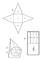
- a mapping method is also conceivable in which an all-round image of the spherical surface 1201 is projected onto a quadrangular pyramid 1202 and developed on a plane 1203.
- the video data projected on the bottom surface # 1 of the quadrangular pyramid and the side surfaces # 2 to # 5 is mapped onto a plane 1203 of two-dimensional coordinates (UV) as shown in the figure.
- the video data mapped on the two-dimensional UV plane 1203 is H.264.
- the video data can be compressed and encoded using a standard video data compression encoding method such as H.264, and transmitted and stored.
- the image data developed on the two-dimensional seat plane is mapped onto the spherical surface based on the mapping method, that is, the correspondence between the two-dimensional coordinates (UV) and the original three-dimensional coordinates (XYZ). Do it.
- the mapping method in which the entire sky image of the spherical surface 1201 is projected onto the quadrangular pyramid 1202 and developed on the plane 1203, the image information of the spherical surface 1201 is mapped on the bottom surface with high resolution.
- the four sides are characterized by low-resolution mapping. For example, if the quadrangular pyramid 1202 is arranged so that the gazing point or the point of interest is included in the bottom surface and the whole sky video is projected, compression encoding can be performed efficiently.
- the data amount can be reduced to about 80%.
- the area mapped on the bottom surface becomes large, and a large area that can maintain high resolution can be left.
- the amount reduction rate is low.
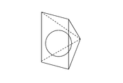
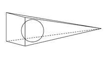
- a spherical surface is projected onto a narrow (or elongated) quadrangular pyramid (see FIG. 14), the area mapped to the bottom surface becomes narrow while maintaining high resolution, and the amount of data can be reduced. .
- the area to be watched or focused (important as visual information) is wide, the whole sky image is projected onto a wide quadrangular pyramid, and the area to be watched or focused is narrow (for example, kitchen tap water)
- the amount of data can be greatly reduced by mapping to a narrow quadrangular pyramid. Therefore, it is necessary to map all-round video according to the situation, such as what kind of video is desired to be delivered from the video providing apparatus or which part of the all-round video is focused on the video playback apparatus side.
- the shape of the pyramid may be selected adaptively. Of course, the same effect as described above can be obtained by mapping to a polygonal pyramid other than a quadrangular pyramid. Further, the polygonal cone that projects the spherical surface is not limited to a regular polygonal pyramid.
- FIGS. 10 to 14 show an example in which an all-sky image is mapped onto a three-dimensional model having a geometric shape such as a cylinder, a cube, or a pyramid, and then the three-dimensional model is developed on a plane.
- an application example in which an all-sky image is mapped to an object having an arbitrary shape is further conceivable. For example, you may make it project on the three-dimensional model according to the shape of the space used as the imaged subject. Specifically, in the case of an all-sky image obtained by capturing an image of the room, the entire sky composed of the four-side wall, ceiling, floor, etc.
- a three-dimensional model 1501 such as a rectangular parallelepiped approximating the shape of the room.
- the peripheral image 1502 may be projected (see FIG. 15) and mapped to a two-dimensional plane.
- the all-sky video is stored and played back as it is as high-quality video such as 4K, 8K, and 16K captured by the video providing device. If restrictions such as storage capacity and transmission load are not taken into consideration, it is preferable to maintain the image quality of the original all-around video by mapping by the cylindrical projection method. However, the original video has a large amount of data, and there is a problem of storage capacity load during storage and bandwidth load during transmission. For this reason, the present applicant considers that it is preferable to adaptively switch the shape of the three-dimensional model for mapping the all-sky image and perform compression encoding at the time of storage or transmission.
- a broadband transmission path is secured between the video providing apparatus 101 and the distribution server 103, but a transmission band from the distribution server 103 to the video reproduction apparatus 102 is not guaranteed.
- the all-sky video captured by the video providing apparatus 101 is transmitted to the distribution server 103 with high image quality such as 4K, 8K, and 16K and stored in the distribution server 103.
- compression encoding processing is performed in consideration of the communication load.
- All of the above-mentioned compression methods of the whole sky video project the whole sky video once onto a three-dimensional model (cube, square pyramid, etc.) This is common in that the model is developed, mapped onto a two-dimensional UV plane, converted into the two-dimensional moving image data, and then compressed and encoded.
- H.264 is used for compression encoding.
- a standard method such as H.264 can be used, but of course, it is not limited to the standard compression encoding method.
- the image quality in the line of sight deteriorates, but according to the mapping method in which projection is performed on a cube, the quality of the image can be made uniform over the entire circumference. Further, according to the mapping method for projecting onto the quadrangular pyramid, it is possible to increase the data reduction amount as a whole by reducing the image quality of other areas while maintaining the image projected on the bottom surface with high image quality.
- the size of the area to keep high image quality and the data reduction amount can be controlled by the size of the bottom surface of the quadrangular pyramid to be projected.
- image quality can be guaranteed uniformly throughout the video and texture mapping errors can be eliminated. Get smaller.
- mapping method is optimal changes dynamically depending on the situation.
- the all-sky video mapping method may be dynamically switched according to the situation.
- the following (1) to (5) can be exemplified.
- Optimum mapping method based on the situation on the video providing device side For example, a person who looks at a real estate property or a salesperson who accompanies the insider is identified by speech, behavior, gestures, etc.
- a mapping method using a quadrangular pyramid or a cube that can guarantee the image quality of the area is appropriate when it is instructed or prompted to pay attention to the area.
- a mapping method using a quadrangular pyramid that can increase the data reduction amount other than the region of interest is more preferable.
- the mapping method using a cube is used, but the resolution is not high but the video is uniform. Is preferably transmitted.
- the mapping method may be switched adaptively according to (in the kitchen, in the living room, in the large room, in the private room, on the veranda).
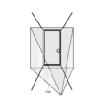
- the bottom of the kitchen is turned as shown in FIG. Further, it can be said that a mapping method for projecting the whole sky image onto the quadrangular pyramid 1600 is appropriate.
- a mapping method for projecting the whole sky image onto the quadrangular pyramid 1600 is appropriate.
- the bottom of the quadrangular pyramid 1600 that projects the whole sky image is narrowed toward the subject, and only that subject is more It may be possible to transmit at high resolution.
- the mapping method can project a whole sky image of a three-dimensional model such as a cube and transmit the whole image with uniform resolution and image quality.
- the distribution server when the distribution server receives a signal indicating the situation at the time of shooting the all-sky video from the video providing device and distributes the all-sky video to the video playback device, the distribution server is based on information included in the signal.
- the switching of the mapping method may be controlled.
- Optimal mapping method based on the situation on the video playback device side
- the user of the video playback device views the real-time video currently sent from the video providing device or the archive video recorded on the distribution server, When looking at a real estate property from a distance, you have a strong interest in a specific subject, or you want to watch a specific subject (or want to see it again), in other words, through speech, behavior, gestures, etc.
- a mapping method using a quadrangular pyramid or a cube that can guarantee the image quality of the subject is appropriate.
- a mapping method using a quadrangular pyramid that can increase the amount of data reduction other than the subject of interest is more preferable.
- a mapping method using a cube is used. It is preferable to transmit a uniform image although the resolution is not high.
- the video playback apparatus transmits information on the user's line-of-sight direction, head position, or posture measured by the sensor unit 609 to a distribution server (or video providing apparatus) that is the distribution source of the all-sky video. May be. Then, on the distribution server (or video providing device) side, the moving image data compressed and encoded using a mapping method for projecting the whole sky video onto a quadrangular pyramid with the bottom face in the direction of the user's line of sight is transmitted to the video playback device. You may do it.
- the video reproduction apparatus collects a voice request from the user (want to know the atmosphere of the entire room or want to see the furniture) at the sound collection unit 607, and gives an instruction based on the voice recognition result. You may make it transmit to the delivery server (or video provision apparatus) which is a delivery source of all the sky images.
- the distribution server receives a signal indicating a situation at the time of viewing the all-sky video from the video reproduction device as a distribution destination, and controls switching of the mapping method based on information included in the signal. That's fine.
- mapping method may be adaptively switched based on the spatial information inspected.
- a mapping method suitable for each space or a change in space is defined in advance, for example, when walking in a narrow corridor, entering a large room from the corridor, or conversely moving from the room to the corridor. Then, the spatial information being inspected is monitored, and the mapping method is adaptively switched according to the spatial information and changes in the space.
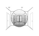
- the whole sky image is projected on the square pyramid 1700 with the bottom surface facing the user's traveling direction (front direction) or rearward.
- Apply mapping method the video playback device displays an image in which the back door has a high resolution.
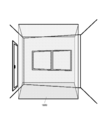
- the mapping method is switched to projecting the entire sky image onto the cube 1800 as shown in FIG.
- the video playback device can also view the whole sky video with the same resolution in the entire room.
- the distribution server may receive a signal indicating spatial information from the video providing device and control switching of the mapping method based on information included in the signal.
- the distribution server may control the switching of the mapping method based on spatial information obtained by analyzing the whole sky video.
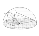
- a mapping method of projecting an all-sky video on a quadrangular pyramid 1900 having a bottom surface directed to a specific area may be multicast to a plurality of video playback devices by applying a mapping method of projecting the whole sky video.
- the line of sight is directed to the image projected on the side of the quadrangular pyramid
- the delivery server unicasts a different compressed and encoded video for each video playback device. Maximum satisfaction can be obtained with all video playback devices.
- the compression rate of individual unicast data is high, there is a problem that the communication load increases with the delivery of a large number of unicast data.
- the distribution server receives a signal indicating the line-of-sight direction from each of a plurality of video playback devices serving as distribution destinations, and controls the switching of the mapping method in consideration of other situations such as a communication load. That's fine.
- mapping method according to load The above (1) to (4) are basically based on the situation on the video providing device side (or on-site spot of real estate property), or on the video playback device side (or This is an appropriate mapping method according to the situation of the viewer of the all-sky image captured in the interior. Even with an appropriate mapping method for each situation, real-time distribution (or uninterrupted video streaming) may be difficult from the viewpoint of communication load.
- a communication load is applied to each of the transmission path between the video providing apparatus 101 and the distribution server 103 and the transmission path from the distribution server 103 to the video reproduction apparatus 102. While the transmission path between the video providing apparatus 101 and the distribution server 103 secures a wide band, the operation of the system in which the transmission band from the distribution server 103 to the video reproduction apparatus 102 is not guaranteed depends on the transmission load from the distribution server 103. There may be a case where a mapping method that does not conform to the situation of the video providing device or the video playback device should be selected.
- the distribution server compresses and encodes the whole sky video by a mapping method using a quadrangular pyramid with a higher compression rate. May be distributed to a video playback device.
- the total transmission data amount is If it becomes enormous, it may be switched to multicast distribution of data compressed and encoded by a mapping method using a common quadrangular pyramid.
- the distribution server may monitor the state of the transmission path such as a communication load in the transmission path used for distributing the all-sky video and adaptively control the switching of the mapping method according to the state of the transmission path.
- the distribution server measures the number of packet retransmissions or obtains feedback information such as packet error rate and received signal strength (however, in the case of wireless communication) from the video playback device that is the distribution destination, The status of the transmission line can be monitored.
- FIG. 21 shows a schematic processing procedure for switching the all-sky video mapping method dynamically and legally in the form of a flowchart.
- This processing procedure is basically assumed to be performed when the all-sky video is distributed from the distribution server to the video playback device.
- the all-round video is transmitted from the video providing device to the distribution server. It can also be carried out when transmitting, or when transmitting directly from the video providing apparatus (not via the distribution server) to the video reproduction apparatus.
- step S2101 information on the situation in which the all-sky video is distributed is acquired (step S2101).
- the situation mentioned here includes the situation on the video providing device side, the situation on the video playback device side, the spatial information on the all-sky video, the situation in the case of distributing video to a plurality of video playback devices, and the communication load. Etc. are included.
- step S2102 it is checked whether or not the currently set mapping method is compatible with the situation grasped in step S2101 (step S2102).
- step S2102 If the currently set mapping method is suitable for the current situation (Yes in step S2102), the all-sky video is compressed and encoded (step S2104) and the video reproduction device without changing the mapping method. (Step S2105) and repeatedly executed.
- Step S2102 if the currently set mapping method does not match the current situation (No in step S2102), the mapping method is switched to the current situation (step S2103), and compression of the whole sky video is performed. (Step S2104) and distribution to the video reproduction device is executed (Step S2105).
- the mapping method is switched adaptively whenever the situation changes.
- step S2101 If a plurality of situations are acquired in step S2101, and the mapping method suitable for each situation is different, the priority of each situation may be determined, and the mapping method suitable for the situation having a higher priority may be applied. .
- the mapping method should be determined taking the communication load as the highest priority.
- mapping method may be determined in consideration of the above.
- the mapping method may be determined with priority given to the situation on the video playback device side.
- mapping methods are common in that all-sky video is compressed and encoded in the following procedure.
- a three-dimensional model for projecting an all-sky image is adaptively selected based on the situation.
- Projecting the image information of the all-sky video on each side of the three-dimensional model is developed, and the image information projected on each side surface is UV-mapped on the two-dimensional plane.
- Image information that has become a two-dimensional plane is represented by H.264.
- Compression encoding is performed using a standard moving image data compression encoding method such as H.264.
- the full-sky video may be restored in the reverse procedure.
- the received compressed encoded video is converted to H.264.
- Decoding is performed according to a specified compression encoding method such as H.264.
- the image information mapped on each side surface of the three-dimensional model is back-projected onto a spherical surface to restore the whole sky image.
- a mapping method is known between the transmission side (for example, distribution server) and the reception side (for example, video playback device) of compressed and encoded video, such as when performing UV mapping of all-sky video using the same 3D model at all times In this case, it is sufficient to transmit only the encoded compressed video data.
- the mapping method used on the transmission side to compress and encode all-sky video the receiving side Will be unknown. For this reason, when transmitting the compression-encoded all-around video, it is preferable to transmit information for notifying the mapping method.
- FIG. 22 shows a transmission format example of the compression-encoded all-around video.
- the first half part indicated by reference numeral 2201 is compression-encoded video data UV-mapped on a two-dimensional plane.
- the latter half portion indicated by reference number 2202 is mapping method data relating to a method of mapping the whole sky image to a two-dimensional plane, and includes shape data of a three-dimensional model used at the time of UV mapping.
- FIG. 23 shows a syntax example of the compression-encoded all-sky video.
- data H.264
- the mapping data (UV mapping) is information for designating a three-dimensional model for projecting the whole sky image.
- Textture, vertex, UV is a texture, a vertex, and a UV map (correspondence table of XYZ coordinates of the whole sky image and UV coordinates of the two-dimensional plane).
- a real-time image or an archive image captured of a real estate property can be suitably viewed, and a realistic look can be realized even from a remote location of the property. Can do.
- the present specification has been described mainly with respect to an embodiment in which the technology disclosed in this specification is applied to a real estate property inspection system, the gist of the technology disclosed in this specification is not limited thereto. .
- the technology disclosed in this specification can be applied to video transmission in various industrial fields. For example, medical sites such as surgery, construction sites such as civil engineering, airplane and helicopter operations, car driver navigation, sports instruction and coaching, various industrial work support, nursing support, human resource dispatch Can be used for applications.
- the technology disclosed in the present specification can be used for concerts, sports watching, and SNS (Social Network Service).
- a receiving unit that receives a three-dimensional image
- a storage unit that holds a three-dimensional model for mapping the three-dimensional image to a two-dimensional image
- a transmission unit for transmitting the two-dimensional image
- a control unit Comprising The control unit determines a three-dimensional model to be used based on an instruction from a user or a surrounding environment, maps the three-dimensional image to a two-dimensional image based on the determined three-dimensional model, and the two-dimensional image Is transmitted from the transmitter.
- Information processing device that receives a three-dimensional image
- a storage unit that holds a three-dimensional model for mapping the three-dimensional image to a two-dimensional image
- a transmission unit for transmitting the two-dimensional image
- a control unit Comprising The control unit determines a three-dimensional model to be used based on an instruction from a user or a surrounding environment, maps the three-dimensional image to a two-dimensional image based on the determined three-dimensional model, and the two-dimensional image Is transmitted from the transmitter.
- the receiving unit receives a whole sky video as the three-dimensional image, The control unit switches and controls a shape for mapping the whole sky image among a plurality of three-dimensional models including at least one of a shape of a cylinder, a cube, a quadrangular pyramid, and a subject.
- the receiving unit receives a first signal from a first device that captures the all-sky video, The control unit performs the switching control based on information included in the first signal.
- (4) The control unit performs the switching control according to a user instruction included in the first signal.
- the control unit performs the switching control according to information indicating a situation at the time of imaging included in the first signal.
- the control unit switches to mapping using a quadrangular pyramid with a bottom surface facing the subject, based on the subject information included in the first signal.
- the transmission unit transmits the two-dimensional image obtained by mapping the whole sky video to a second device, The control unit performs the switching control based on information included in a second signal received from the second device.
- (8) The control unit performs the switching control based on subject information included in the second signal.
- the control unit switches to mapping using a quadrangular pyramid with a bottom surface facing the subject.
- the control unit switches to mapping using a quadrangular pyramid with a bottom face in the direction of the line of sight based on the line-of-sight information included in the second signal.
- the control unit performs the switching control according to a user instruction included in the second signal.
- the transmission unit is a transmission unit that transmits the whole sky video to a plurality of second devices, The control unit performs the switching control based on line-of-sight information included in the second signal received from each of the plurality of second devices.
- the control unit causes the plurality of second devices to transmit unicast each two-dimensional image mapped using a quadrangular pyramid with a bottom face in the direction of each line of sight.
- the control unit multicast-transmits a two-dimensional image mapped using a quadrangular pyramid with a bottom surface directed to an area including most lines of sight.
- the information processing apparatus according to (12) above. further comprising a monitoring unit for monitoring a state of a transmission path for transmitting the all-sky video, The control unit performs the switching control based on the state of the transmission path.
- the control unit causes the transmission unit to transmit the two-dimensional image in a transmission format including information for specifying the three-dimensional model used for the mapping.
- the information processing apparatus according to (1) above.
- a method for transmitting three-dimensional image data, Two-dimensional map image data in which the three-dimensional image is mapped to a two-dimensional image based on the three-dimensional model and ancillary data for specifying the three-dimensional model used for the mapping are made into one data set. Steps, Transmitting the data set; A method for transmitting three-dimensional image data.
- DESCRIPTION OF SYMBOLS 100 ... Video viewing system 101 ... Video provision apparatus, 102 ... Video reproduction apparatus 200 ... Video viewing system 201 ... Video provision apparatus, 202 ... Video reproduction apparatus 300 ... Video viewing system 301 ... Video provision apparatus, 302 ... Video reproduction apparatus 400 ... Video viewing system 401 ... Video providing device, 402 ... Video playback device 500 ... Information processing device (video providing device) 501: Imaging unit, 503: Video encoding unit 504 ... Audio input unit, 505 ... Audio encoding unit 506 ... Multiplexing unit, 507 ... Communication unit, 508 ... Video decoding unit 509 ... Image processing unit, 510 ... Display unit, 511 ... Audio decoding unit 512 ...
- Audio output unit 513 ...
- Control unit 600 Information processing device (video reproduction device) 601 ... Communication unit, 602 ... Separation unit (DEMUX) 603: Audio decoding unit, 604 ... Audio output unit, 605 ... Video decoding unit, 606 ... Display unit, 607 ... Sound collection unit, 608 ... Audio encoding unit, 609 ... Sensor unit, 610 ... Control unit
Landscapes
- Engineering & Computer Science (AREA)
- Multimedia (AREA)
- Signal Processing (AREA)
- Physics & Mathematics (AREA)
- General Physics & Mathematics (AREA)
- Theoretical Computer Science (AREA)
- Computer Graphics (AREA)
- Software Systems (AREA)
- Biomedical Technology (AREA)
- Computer Hardware Design (AREA)
- Databases & Information Systems (AREA)
- Health & Medical Sciences (AREA)
- Life Sciences & Earth Sciences (AREA)
- Chemical & Material Sciences (AREA)
- Analytical Chemistry (AREA)
- General Engineering & Computer Science (AREA)
- Biophysics (AREA)
- General Health & Medical Sciences (AREA)
- Neurosurgery (AREA)
- Geometry (AREA)
- Processing Or Creating Images (AREA)
- Two-Way Televisions, Distribution Of Moving Picture Or The Like (AREA)
Abstract
Description
3次元画像を受信する受信部と、
前記3次元画像を2次元画像にマッピングするための3次元モデルを保持する記憶部と、
前記2次元画像を送信する送信部と、
制御部と、
を具備し、
前記制御部は、ユーザーからの指示又は周辺環境に基づいて、使用する3次元モデルを決定し、前記決定した3次元モデルに基づいて前記3次元画像を2次元画像にマッピングし、前記2次元画像を前記送信部より送信する、
情報処理装置である。
3次元画像を受信する受信ステップと、
前記3次元画像を2次元画像にマッピングするための3次元モデルを記憶部に保持する記憶ステップと、
前記2次元画像を送信する送信ステップと、
制御ステップと、
を有し、
前記制御ステップでは、ユーザーからの指示又は周辺環境に基づいて、使用する3次元モデルを決定し、前記決定した3次元モデルに基づいて前記3次元画像を2次元画像にマッピングし、前記2次元画像を前記送信ステップにおいて送信する、情報処理方法である。
3次元モデルに基づいて前記3次元画像が2次元画像にマッピングされた2次元マップ画像データと、前記マッピングに用いられた前記3次元モデルを特定するための付属データを1つのデータ・セットにするステップと、
前記データ・セットを伝送するステップと、
を有する3次元画像データの伝送方法である。
A-1.システム構成
図1には、映像を視聴する映像視聴システム100の構成例を模式的に示している。映像視聴システム100は、映像を提供する1台の映像提供装置101と、映像を再生する1台の映像再生装置102からなり、1対1のネットワーク・トポロジーを構成している。映像提供装置101と映像再生装置102間は、例えば無線又は有線のLAN(Local Area Network)、あるいはインターネットなどの広域ネットワークを介して相互接続されている。
B-1.映像提供装置の構成
図5には、映像視聴システム100~400において映像提供装置として機能することができる情報処理装置500の機能的構成を模式的に示している。図示の情報処理装置500は、撮像部501と、映像符号化部503と、音声入力部504と、音声符号化部505と、多重化部(MUX)506と、通信部507と、映像復号部508と、画像処理部509と、表示部510と、音声復号部511と、音声出力部512と、制御部513を備えている。以下、各部501~513について説明する。
図6には、映像視聴システム100~400において映像再生装置として機能することができる情報処理装置600の機能的構成を模式的に示している。図示の情報処理装置600は、通信部601と、分離部(DEMUX)602と、音声復号部603と、音声出力部604と、映像復号部605と、表示部606と、集音部607と、音声符号化部608と、センサー部609と、制御部610を備えている。以下、各部601~610について説明する。
上記A項では、映像提供装置でリアルタイムに撮像されたリアル映像を映像再生装置で視聴する仕組みについて言及した。これに対し、映像提供装置で撮像した映像を外部装置(配信サーバー)に一旦記録し、映像再生装置側ではアーカイブ映像を外部装置から視聴するという実施態様もある。
図8には、映像視聴システム100を不動産物件の内見に適用した例を示している。参照番号801は、不動産の物件(現地)にいるユーザー(物件の内見者、若しくは不動産会社の営業マンなど)であり、映像提供装置(前述)を所持若しくは装備している。一方、参照番号802は、現地には赴かず、現地から離間した場所(例えば、不動産会社の店舗や自宅など)で物件の情報を閲覧するユーザーであり、映像再生装置(前述)を用いて、映像提供装置が撮像する物件の映像を視聴している。
本実施形態に係る映像視聴システム100では、不動産の物件の全天周映像を映像提供装置で撮像し、物件からは遠隔に設置された映像再生装置で視聴することを想定している。
全天周映像は、映像提供装置で撮像された4K、8K、16Kなど高画質の映像のまま保存し、再生されることが好ましい。記憶容量や伝送負荷などの制約を考慮しなければ、円筒投影法によりマッピングして元の全天周映像の画質を保つことが好ましい。しかしながら、元の映像はデータ量が大きく、蓄積時の記憶容量の負荷や、伝送時の帯域負荷の問題がある。このため、全天周映像をマッピングする3次元モデルの形状を適応的に切り替えて、蓄積時や伝送時に圧縮符号化することが好ましい、と本出願人は思料する。
例えば、不動産の物件を内見している人、又は内見者に同行している営業マンが、言動や挙動、ジェスチャーなどにより、特定の領域に注視若しくは着目すべきことを指示し又は促した場合には、その領域の画質を保証することができる四角錐又は立方体を用いたマッピング方法が適切である。
例えば、映像再生装置のユーザーが、映像提供装置から現在送られてくるリアルタイム映像、あるいは配信サーバーに記録されたアーカイブ映像を視聴して、遠隔から不動産の物件を内見している際に、言動や挙動、ジェスチャーなどにより、特定の被写体に強い関心を持ち、あるいは特定の被写体を注視したい(又は、もう一度見たい)こと、言い換えれば注目したい被写体を意思表示した場合には、その被写体の画質を保証することができる四角錐又は立方体を用いたマッピング方法が適切である。また、ユーザーが注視若しくは着目している領域が狭く、そこから外れた領域に関心がない場合(例えば、キッチンの水道水の蛇口やドアのノブなど、調度品の特定の被写体を注視している場合)には、注目している被写体以外のデータ削減量を大きくすることができる四角錐を用いたマッピング方法がより好ましい。一方、ユーザーが物件全般の雰囲気を知りたい場合(例えば、廊下を抜けて、リビング・ルームに入った瞬間の映像を視聴しているときなど)には、立方体を用いたマッピング方法を用いて、解像度は高くないが均一な映像を伝送することが好ましい。
内見している空間情報に基づいて、適応的にマッピング方法を切り替えるようにしてもよい。例えば、狭い廊下を歩いているとき、廊下から広い部屋に入ったとき、逆に、部屋から廊下に移ったときなど、空間毎、若しくは空間の変化に適合するマッピング方法をあらかじめ規定しておく。そして、内見している最中の空間情報をモニタリングして、空間情報や空間の変化に応じて、適応的にマッピング方法を切り替えるようにする。
配信サーバーから、1つの全天周映像を複数の映像再生装置に配信する場合、個々の映像再生装置で全天周映像を視聴する視線方向がまちまちであることを想定して、全天周映像を立方体に投影するマッピング方法(図11を参照のこと)を適用して、同じ圧縮符号化映像を複数の映像再生装置にマルチキャストするようにしてもよい。個々の映像再生装置で全天周映像を視聴する視線方向がまちまちであっても、いずれの視線方向の映像も均一な解像度すなわち一定の画質を保つことができる。すべての映像再生装置において、平均的な満足感が得られる全天周映像のマルチキャスト配信方法ということもできる。
上記の(1)~(4)は、基本的に、映像提供装置側(若しくは、不動産の物件の内見現場)の状況、又は、映像再生装置側(若しくは、内見で撮像された全天周映像の視聴者)の状況に応じた適切なマッピング方法である。状況毎に適切なマッピング方法であっても、通信負荷の観点から、リアルタイム配信(若しくは、途切れのない映像ストリーミング)が困難な場合もある。
(2)3次元モデルの各側面に全天周映像の画像情報を投影する。
(3)3次元モデルを展開して、その各側面に投影された画像情報を2次元平面にUVマッピングする。
(4)2次元平面となった画像情報を、H.264などの標準的な動画データの圧縮符号化方式を用いて圧縮符号化する。
(2)2次元平面上の復号された画像情報を、3次元モデルの各側面に逆UVマッピングする。
(3)3次元モデルの各側面にマッピングされた画像情報を、球面に逆投影して、全天周映像を復元する。
(1)3次元画像を受信する受信部と、
前記3次元画像を2次元画像にマッピングするための3次元モデルを保持する記憶部と、
前記2次元画像を送信する送信部と、
制御部と、
を具備し、
前記制御部は、ユーザーからの指示又は周辺環境に基づいて、使用する3次元モデルを決定し、前記決定した3次元モデルに基づいて前記3次元画像を2次元画像にマッピングし、前記2次元画像を前記送信部より送信する、
情報処理装置。
(2)前記受信部は、前記3次元画像として全天周映像を受信し、
前記制御部は、前記全天周映像をマッピングする形状を、円筒、立方体、四角錐、被写体の形状のうち少なくとも1つを含む、複数の3次元モデルの中で切り替え制御する、
上記(1)に記載の情報処理装置。
(3)前記受信部は、前記全天周映像を撮像する第1の装置から第1の信号を受信し、
前記制御部は、前記第1の信号に含まれる情報に基づいて前記切り替え制御を行なう、
上記(2)の記載の情報処理装置。
(4)前記制御部は、前記第1の信号に含まれるユーザーの指示に応じて前記切り替え制御を行なう、
上記(3)に記載の情報処理装置。
(5)前記制御部は、前記第1の信号に含まれる撮像時の状況を示す情報に応じて前記切り替え制御を行なう、
上記(3)に記載の情報処理装置。
(6)前記制御部は、前記第1の信号に含まれる被写体の情報に基づいて、前記被写体に底面を向けた四角錐を用いたマッピングに切り替える、
上記(3)に記載の情報処理装置。
(7)前記送信部は、前記全天周映像をマッピングした前記2次元画像を第2の装置に送信し、
前記制御部は、前記第2の装置から受信する第2の信号に含まれる情報に基づいて前記切り替え制御を行なう、
上記(2)に記載の情報処理装置。
(8)前記制御部は、前記第2の信号に含まれる被写体の情報に基づいて前記切り替え制御を行なう、
上記(7)に記載の情報処理装置。
(9)前記制御部は、前記被写体に底面を向けた四角錐を用いたマッピングに切り替える、
上記(8)に記載の情報処理装置。
(10)前記制御部は、前記第2の信号に含まれる視線情報に基づいて、視線の方向に底面を向けた四角錐を用いたマッピングに切り替える、
上記(7)に記載の情報処理装置。
(11)前記制御部は、前記第2の信号に含まれるユーザーの指示に応じて前記切り替え制御を行なう、
上記(7)に記載の情報処理装置。
(12)前記送信部は前記全天周映像を複数の第2の装置に送信する送信部し、
前記制御部は、前記複数の第2の装置の各々から受信する前記第2の信号に含まれる視線情報に基づいて前記切り替え制御を行なう、
上記(2)に記載の情報処理装置。
(13)前記制御部は、前記複数の第2の装置に対して、各々の視線の方向に底面を向けた四角錐を用いてマッピングした2次元画像をそれぞれユニキャスト送信させる、
上記(12)に記載の情報処理装置。
(14)前記制御部は、大部分の視線を含む領域に底面を向けた四角錐を用いてマッピングした2次元画像をマルチキャスト送信させる、
上記(12)に記載の情報処理装置。
(15)前記全天周映像を伝送する伝送路の状況をモニタリングするモニタリング部をさらに備え、
前記制御部は、前記伝送路の状況に基づいて前記切り替え制御を行なう、
上記(2)に記載の情報処理装置。
(16)前記制御部は、前記マッピングに使用された3次元モデルを特定するための情報を含んだ伝送フォーマットで前記2次元画像を前記送信部より伝送させる、
上記(1)に記載の情報処理装置。
(17)3次元画像を受信する受信ステップと、
前記3次元画像を2次元画像にマッピングするための3次元モデルを記憶部に保持する記憶ステップと、
前記2次元画像を送信する送信ステップと、
制御ステップと、
を有し、
前記制御ステップでは、ユーザーからの指示又は周辺環境に基づいて、使用する3次元モデルを決定し、前記決定した3次元モデルに基づいて前記3次元画像を2次元画像にマッピングし、前記2次元画像を前記送信ステップにおいて送信する、
情報処理方法。
(18)3次元画像データの伝送方法であって、
3次元モデルに基づいて前記3次元画像が2次元画像にマッピングされた2次元マップ画像データと、前記マッピングに用いられた前記3次元モデルを特定するための付属データを1つのデータ・セットにするステップと、
前記データ・セットを伝送するステップと、
を有する3次元画像データの伝送方法。
101…映像提供装置、102…映像再生装置
200…映像視聴システム
201…映像提供装置、202…映像再生装置
300…映像視聴システム
301…映像提供装置、302…映像再生装置
400…映像視聴システム
401…映像提供装置、402…映像再生装置
500…情報処理装置(映像提供装置)
501…撮像部、503…映像符号化部
504…音声入力部、505…音声符号化部
506…多重化部、507…通信部、508…映像復号部
509…画像処理部、510…表示部、511…音声復号部
512…音声出力部、513…制御部
600…情報処理装置(映像再生装置)
601…通信部、602…分離部(DEMUX)
603…音声復号部、604…音声出力部
605…映像復号部、606…表示部
607…集音部、608…音声符号化部
609…センサー部、610…制御部
Claims (18)
- 3次元画像を受信する受信部と、
前記3次元画像を2次元画像にマッピングするための3次元モデルを保持する記憶部と、
前記2次元画像を送信する送信部と、
制御部と、
を具備し、
前記制御部は、ユーザーからの指示又は周辺環境に基づいて、使用する3次元モデルを決定し、前記決定した3次元モデルに基づいて前記3次元画像を2次元画像にマッピングし、前記2次元画像を前記送信部より送信する、
情報処理装置。 - 前記受信部は、前記3次元画像として全天周映像を受信し、
前記制御部は、前記全天周映像をマッピングする形状を、円筒、立方体、四角錐、被写体の形状のうち少なくとも1つを含む、複数の3次元モデルの中で切り替え制御する、
請求項1に記載の情報処理装置。 - 前記受信部は、前記全天周映像を撮像する第1の装置から第1の信号を受信し、
前記制御部は、前記第1の信号に含まれる情報に基づいて前記切り替え制御を行なう、
請求項2の記載の情報処理装置。 - 前記制御部は、前記第1の信号に含まれるユーザーの指示に応じて前記切り替え制御を行なう、
請求項3に記載の情報処理装置。 - 前記制御部は、前記第1の信号に含まれる撮像時の状況を示す情報に応じて前記切り替え制御を行なう、
請求項3に記載の情報処理装置。 - 前記制御部は、前記第1の信号に含まれる被写体の情報に基づいて、前記被写体に底面を向けた四角錐を用いたマッピングに切り替える、
請求項3に記載の情報処理装置。 - 前記送信部は、前記全天周映像をマッピングした前記2次元画像を第2の装置に送信し、
前記制御部は、前記第2の装置から受信する第2の信号に含まれる情報に基づいて前記切り替え制御を行なう、
請求項2に記載の情報処理装置。 - 前記制御部は、前記第2の信号に含まれる被写体の情報に基づいて前記切り替え制御を行なう、
請求項7に記載の情報処理装置。 - 前記制御部は、前記被写体に底面を向けた四角錐を用いたマッピングに切り替える、
請求項8に記載の情報処理装置。 - 前記制御部は、前記第2の信号に含まれる視線情報に基づいて、視線の方向に底面を向けた四角錐を用いたマッピングに切り替える、
請求項7に記載の情報処理装置。 - 前記制御部は、前記第2の信号に含まれるユーザーの指示に応じて前記切り替え制御を行なう、
請求項7に記載の情報処理装置。 - 前記送信部は前記全天周映像を複数の第2の装置に送信する送信部し、
前記制御部は、前記複数の第2の装置の各々から受信する前記第2の信号に含まれる視線情報に基づいて前記切り替え制御を行なう、
請求項2に記載の情報処理装置。 - 前記制御部は、前記複数の第2の装置に対して、各々の視線の方向に底面を向けた四角錐を用いてマッピングした2次元画像をそれぞれユニキャスト送信させる、
請求項12に記載の情報処理装置。 - 前記制御部は、大部分の視線を含む領域に底面を向けた四角錐を用いてマッピングした2次元画像をマルチキャスト送信させる、
請求項12に記載の情報処理装置。 - 前記全天周映像を伝送する伝送路の状況をモニタリングするモニタリング部をさらに備え、
前記制御部は、前記伝送路の状況に基づいて前記切り替え制御を行なう、
請求項2に記載の情報処理装置。 - 前記制御部は、前記マッピングに使用された3次元モデルを特定するための情報を含んだ伝送フォーマットで前記2次元画像を前記送信部より伝送させる、
請求項1に記載の情報処理装置。 - 3次元画像を受信する受信ステップと、
前記3次元画像を2次元画像にマッピングするための3次元モデルを記憶部に保持する記憶ステップと、
前記2次元画像を送信する送信ステップと、
制御ステップと、
を有し、
前記制御ステップでは、ユーザーからの指示又は周辺環境に基づいて、使用する3次元モデルを決定し、前記決定した3次元モデルに基づいて前記3次元画像を2次元画像にマッピングし、前記2次元画像を前記送信ステップにおいて送信する、
情報処理方法。 - 3次元画像データの伝送方法であって、
3次元モデルに基づいて前記3次元画像が2次元画像にマッピングされた2次元マップ画像データと、前記マッピングに用いられた前記3次元モデルを特定するための付属データを1つのデータ・セットにするステップと、
前記データ・セットを伝送するステップと、
を有する3次元画像データの伝送方法。
Priority Applications (5)
| Application Number | Priority Date | Filing Date | Title |
|---|---|---|---|
| EP17789110.8A EP3451674A4 (en) | 2016-04-28 | 2017-03-13 | INFORMATION PROCESSING DEVICE AND INFORMATION PROCESSING METHOD AND METHOD FOR TRANSMITTING THREE-DIMENSIONAL IMAGE DATA |
| CN201780024606.0A CN109076253A (zh) | 2016-04-28 | 2017-03-13 | 信息处理装置和信息处理方法、以及三维图像数据发送方法 |
| KR1020187030012A KR20190003496A (ko) | 2016-04-28 | 2017-03-13 | 정보 처리 장치 및 정보 처리 방법, 그리고 3차원 화상 데이터의 전송 방법 |
| JP2018514185A JP6958545B2 (ja) | 2016-04-28 | 2017-03-13 | 情報処理装置及び情報処理方法 |
| US16/092,664 US10531068B2 (en) | 2016-04-28 | 2017-03-13 | Information processing device, information processing method, and three-dimensional image data transmission method |
Applications Claiming Priority (2)
| Application Number | Priority Date | Filing Date | Title |
|---|---|---|---|
| JP2016090280 | 2016-04-28 | ||
| JP2016-090280 | 2016-04-28 |
Publications (1)
| Publication Number | Publication Date |
|---|---|
| WO2017187821A1 true WO2017187821A1 (ja) | 2017-11-02 |
Family
ID=60161495
Family Applications (1)
| Application Number | Title | Priority Date | Filing Date |
|---|---|---|---|
| PCT/JP2017/010034 Ceased WO2017187821A1 (ja) | 2016-04-28 | 2017-03-13 | 情報処理装置及び情報処理方法、並びに3次元画像データの伝送方法 |
Country Status (6)
| Country | Link |
|---|---|
| US (1) | US10531068B2 (ja) |
| EP (1) | EP3451674A4 (ja) |
| JP (1) | JP6958545B2 (ja) |
| KR (1) | KR20190003496A (ja) |
| CN (1) | CN109076253A (ja) |
| WO (1) | WO2017187821A1 (ja) |
Cited By (8)
| Publication number | Priority date | Publication date | Assignee | Title |
|---|---|---|---|---|
| CN109413409A (zh) * | 2018-09-30 | 2019-03-01 | Oppo广东移动通信有限公司 | 一种数据处理方法、mec服务器、终端设备 |
| CN110136050A (zh) * | 2018-02-09 | 2019-08-16 | 深圳市智财家知识产权咨询有限公司 | 基于3d模型转换2d图的方法及系统和计算机可读的存储介质 |
| JP2019149595A (ja) * | 2018-02-26 | 2019-09-05 | 富士ゼロックス株式会社 | 情報処理装置、情報処理システム、動画表示システム及びプログラム |
| JPWO2018134947A1 (ja) * | 2017-01-19 | 2019-11-07 | 株式会社ソニー・インタラクティブエンタテインメント | 画像配信装置 |
| JP2021048506A (ja) * | 2019-09-19 | 2021-03-25 | Kddi株式会社 | 映像シーン情報管理装置 |
| JP7097125B1 (ja) | 2021-12-22 | 2022-07-07 | 株式会社セルシス | 映像生成方法及び画像生成プログラム |
| JP2023095696A (ja) * | 2021-12-24 | 2023-07-06 | 株式会社エクシング | コンテンツ配信システム、及び、カラオケ再生システム |
| WO2023249015A1 (ja) * | 2022-06-24 | 2023-12-28 | 株式会社映像システム | 画像領域生成システム及びプログラム、画像領域表示空間 |
Families Citing this family (4)
| Publication number | Priority date | Publication date | Assignee | Title |
|---|---|---|---|---|
| US10712810B2 (en) | 2017-12-08 | 2020-07-14 | Telefonaktiebolaget Lm Ericsson (Publ) | System and method for interactive 360 video playback based on user location |
| CN112465939B (zh) | 2020-11-25 | 2023-01-24 | 上海哔哩哔哩科技有限公司 | 全景视频渲染方法及系统 |
| CN112950459A (zh) * | 2021-03-23 | 2021-06-11 | 贵州航天云网科技有限公司 | 一种基于微服务技术的3d模型快速复用系统及方法 |
| US20250069288A1 (en) * | 2023-08-22 | 2025-02-27 | Sdc U.S. Smilepay Spv | Systems and methods for automated mesh cleanup |
Citations (4)
| Publication number | Priority date | Publication date | Assignee | Title |
|---|---|---|---|---|
| JP2003141562A (ja) * | 2001-10-29 | 2003-05-16 | Sony Corp | 非平面画像の画像処理装置及び画像処理方法、記憶媒体、並びにコンピュータ・プログラム |
| JP2005056295A (ja) * | 2003-08-07 | 2005-03-03 | Iwane Kenkyusho:Kk | 360度画像変換処理装置 |
| JP2006180022A (ja) * | 2004-12-21 | 2006-07-06 | Konica Minolta Holdings Inc | 画像処理システム |
| WO2015122052A1 (ja) * | 2014-02-17 | 2015-08-20 | 株式会社ソニー・コンピュータエンタテインメント | 画像送信装置、情報処理端末、画像送信方法、情報処理方法、プログラム及び情報記憶媒体 |
Family Cites Families (6)
| Publication number | Priority date | Publication date | Assignee | Title |
|---|---|---|---|---|
| JP2001195491A (ja) | 1999-11-02 | 2001-07-19 | Matsushita Electric Works Ltd | 住空間関連商品の販売支援方法と課金方法及びそのためのシステムと記録媒体 |
| US10163261B2 (en) * | 2014-03-19 | 2018-12-25 | Matterport, Inc. | Selecting two-dimensional imagery data for display within a three-dimensional model |
| JP6044328B2 (ja) * | 2012-12-26 | 2016-12-14 | 株式会社リコー | 画像処理システム、画像処理方法およびプログラム |
| JP6176073B2 (ja) * | 2013-11-14 | 2017-08-09 | 株式会社リコー | 撮影システム及びプログラム |
| US10397543B2 (en) * | 2014-09-03 | 2019-08-27 | Nextvr Inc. | Methods and apparatus for capturing, streaming and/or playing back content |
| US9870646B2 (en) * | 2015-06-26 | 2018-01-16 | Virtual Outfits, Llc | Three-dimensional model generation based on two-dimensional images |
-
2017
- 2017-03-13 KR KR1020187030012A patent/KR20190003496A/ko not_active Withdrawn
- 2017-03-13 WO PCT/JP2017/010034 patent/WO2017187821A1/ja not_active Ceased
- 2017-03-13 US US16/092,664 patent/US10531068B2/en active Active
- 2017-03-13 CN CN201780024606.0A patent/CN109076253A/zh not_active Withdrawn
- 2017-03-13 EP EP17789110.8A patent/EP3451674A4/en not_active Withdrawn
- 2017-03-13 JP JP2018514185A patent/JP6958545B2/ja active Active
Patent Citations (4)
| Publication number | Priority date | Publication date | Assignee | Title |
|---|---|---|---|---|
| JP2003141562A (ja) * | 2001-10-29 | 2003-05-16 | Sony Corp | 非平面画像の画像処理装置及び画像処理方法、記憶媒体、並びにコンピュータ・プログラム |
| JP2005056295A (ja) * | 2003-08-07 | 2005-03-03 | Iwane Kenkyusho:Kk | 360度画像変換処理装置 |
| JP2006180022A (ja) * | 2004-12-21 | 2006-07-06 | Konica Minolta Holdings Inc | 画像処理システム |
| WO2015122052A1 (ja) * | 2014-02-17 | 2015-08-20 | 株式会社ソニー・コンピュータエンタテインメント | 画像送信装置、情報処理端末、画像送信方法、情報処理方法、プログラム及び情報記憶媒体 |
Non-Patent Citations (1)
| Title |
|---|
| See also references of EP3451674A4 * |
Cited By (13)
| Publication number | Priority date | Publication date | Assignee | Title |
|---|---|---|---|---|
| JPWO2018134947A1 (ja) * | 2017-01-19 | 2019-11-07 | 株式会社ソニー・インタラクティブエンタテインメント | 画像配信装置 |
| CN110136050A (zh) * | 2018-02-09 | 2019-08-16 | 深圳市智财家知识产权咨询有限公司 | 基于3d模型转换2d图的方法及系统和计算机可读的存储介质 |
| JP2019149595A (ja) * | 2018-02-26 | 2019-09-05 | 富士ゼロックス株式会社 | 情報処理装置、情報処理システム、動画表示システム及びプログラム |
| JP7091703B2 (ja) | 2018-02-26 | 2022-06-28 | 富士フイルムビジネスイノベーション株式会社 | 情報処理装置、情報処理システム及びプログラム |
| CN109413409A (zh) * | 2018-09-30 | 2019-03-01 | Oppo广东移动通信有限公司 | 一种数据处理方法、mec服务器、终端设备 |
| JP2021048506A (ja) * | 2019-09-19 | 2021-03-25 | Kddi株式会社 | 映像シーン情報管理装置 |
| JP7097125B1 (ja) | 2021-12-22 | 2022-07-07 | 株式会社セルシス | 映像生成方法及び画像生成プログラム |
| WO2023119715A1 (ja) * | 2021-12-22 | 2023-06-29 | 株式会社セルシス | 映像生成方法及び画像生成プログラム |
| JP2023093276A (ja) * | 2021-12-22 | 2023-07-04 | 株式会社セルシス | 映像生成方法及び画像生成プログラム |
| JP2023095696A (ja) * | 2021-12-24 | 2023-07-06 | 株式会社エクシング | コンテンツ配信システム、及び、カラオケ再生システム |
| WO2023249015A1 (ja) * | 2022-06-24 | 2023-12-28 | 株式会社映像システム | 画像領域生成システム及びプログラム、画像領域表示空間 |
| JPWO2023249015A1 (ja) * | 2022-06-24 | 2023-12-28 | ||
| JP7586416B2 (ja) | 2022-06-24 | 2024-11-19 | 株式会社 映像システム | 画像領域生成システム及びプログラム、画像領域表示装置 |
Also Published As
| Publication number | Publication date |
|---|---|
| US10531068B2 (en) | 2020-01-07 |
| CN109076253A (zh) | 2018-12-21 |
| JPWO2017187821A1 (ja) | 2019-02-28 |
| KR20190003496A (ko) | 2019-01-09 |
| JP6958545B2 (ja) | 2021-11-02 |
| EP3451674A1 (en) | 2019-03-06 |
| EP3451674A4 (en) | 2019-03-06 |
| US20190208179A1 (en) | 2019-07-04 |
Similar Documents
| Publication | Publication Date | Title |
|---|---|---|
| JP6958545B2 (ja) | 情報処理装置及び情報処理方法 | |
| US10455184B2 (en) | Display device and information processing terminal device | |
| US11924394B2 (en) | Methods and apparatus for receiving and/or using reduced resolution images | |
| US11140378B2 (en) | Sub-picture-based processing method of 360-degree video data and apparatus therefor | |
| US8831780B2 (en) | System and method for creating virtual presence | |
| EP2490179B1 (en) | Method and apparatus for transmitting and receiving a panoramic video stream | |
| US9591349B2 (en) | Interactive binocular video display | |
| EP3189657B1 (en) | Method and apparatus for transmitting and/or playing back stereoscopic content | |
| US9615177B2 (en) | Wireless immersive experience capture and viewing | |
| US20180225537A1 (en) | Methods and apparatus relating to camera switching and/or making a decision to switch between cameras | |
| US20180249189A1 (en) | Methods and apparatus for use in a system or device where switching between cameras may occur | |
| CN112272817B (zh) | 用于在沉浸式现实中提供音频内容的方法和装置 | |
| WO2017187764A1 (ja) | 情報処理端末装置並びに配信装置 | |
| US20180278995A1 (en) | Information processing apparatus, information processing method, and program | |
| US20220108530A1 (en) | Systems and methods for providing an audio-guided virtual reality tour | |
| KR20110108551A (ko) | 다시점 입체 동영상 송/수신 장치 및 방법 | |
| CN115176223A (zh) | 信息处理装置、信息处理方法和计算机程序 | |
| WO2017187807A1 (ja) | 情報処理端末装置 | |
| Ochi et al. | Dive into remote events: Omnidirectional video streaming with acoustic immersion | |
| Fautier | VR video ecosystem for live distribution |
Legal Events
| Date | Code | Title | Description |
|---|---|---|---|
| WWE | Wipo information: entry into national phase |
Ref document number: 2018514185 Country of ref document: JP |
|
| ENP | Entry into the national phase |
Ref document number: 20187030012 Country of ref document: KR Kind code of ref document: A |
|
| NENP | Non-entry into the national phase |
Ref country code: DE |
|
| WWE | Wipo information: entry into national phase |
Ref document number: 2017789110 Country of ref document: EP |
|
| ENP | Entry into the national phase |
Ref document number: 2017789110 Country of ref document: EP Effective date: 20181128 |
|
| 121 | Ep: the epo has been informed by wipo that ep was designated in this application |
Ref document number: 17789110 Country of ref document: EP Kind code of ref document: A1 |