WO2017187879A1 - 磁気マーカ及び運転支援システム - Google Patents
磁気マーカ及び運転支援システム Download PDFInfo
- Publication number
- WO2017187879A1 WO2017187879A1 PCT/JP2017/013341 JP2017013341W WO2017187879A1 WO 2017187879 A1 WO2017187879 A1 WO 2017187879A1 JP 2017013341 W JP2017013341 W JP 2017013341W WO 2017187879 A1 WO2017187879 A1 WO 2017187879A1
- Authority
- WO
- WIPO (PCT)
- Prior art keywords
- magnetic marker
- magnetic
- vehicle
- information
- marker
- Prior art date
- Legal status (The legal status is an assumption and is not a legal conclusion. Google has not performed a legal analysis and makes no representation as to the accuracy of the status listed.)
- Ceased
Links
Images




Classifications
-
- G—PHYSICS
- G05—CONTROLLING; REGULATING
- G05D—SYSTEMS FOR CONTROLLING OR REGULATING NON-ELECTRIC VARIABLES
- G05D1/00—Control of position, course, altitude or attitude of land, water, air or space vehicles, e.g. using automatic pilots
- G05D1/20—Control system inputs
- G05D1/24—Arrangements for determining position or orientation
- G05D1/243—Means capturing signals occurring naturally from the environment, e.g. ambient optical, acoustic, gravitational or magnetic signals
-
- G—PHYSICS
- G01—MEASURING; TESTING
- G01C—MEASURING DISTANCES, LEVELS OR BEARINGS; SURVEYING; NAVIGATION; GYROSCOPIC INSTRUMENTS; PHOTOGRAMMETRY OR VIDEOGRAMMETRY
- G01C21/00—Navigation; Navigational instruments not provided for in groups G01C1/00 - G01C19/00
- G01C21/04—Navigation; Navigational instruments not provided for in groups G01C1/00 - G01C19/00 by terrestrial means
-
- B—PERFORMING OPERATIONS; TRANSPORTING
- B60—VEHICLES IN GENERAL
- B60W—CONJOINT CONTROL OF VEHICLE SUB-UNITS OF DIFFERENT TYPE OR DIFFERENT FUNCTION; CONTROL SYSTEMS SPECIALLY ADAPTED FOR HYBRID VEHICLES; ROAD VEHICLE DRIVE CONTROL SYSTEMS FOR PURPOSES NOT RELATED TO THE CONTROL OF A PARTICULAR SUB-UNIT
- B60W50/00—Details of control systems for road vehicle drive control not related to the control of a particular sub-unit, e.g. process diagnostic or vehicle driver interfaces
- B60W50/08—Interaction between the driver and the control system
- B60W50/14—Means for informing the driver, warning the driver or prompting a driver intervention
-
- G—PHYSICS
- G01—MEASURING; TESTING
- G01C—MEASURING DISTANCES, LEVELS OR BEARINGS; SURVEYING; NAVIGATION; GYROSCOPIC INSTRUMENTS; PHOTOGRAMMETRY OR VIDEOGRAMMETRY
- G01C21/00—Navigation; Navigational instruments not provided for in groups G01C1/00 - G01C19/00
- G01C21/26—Navigation; Navigational instruments not provided for in groups G01C1/00 - G01C19/00 specially adapted for navigation in a road network
-
- G—PHYSICS
- G05—CONTROLLING; REGULATING
- G05D—SYSTEMS FOR CONTROLLING OR REGULATING NON-ELECTRIC VARIABLES
- G05D1/00—Control of position, course, altitude or attitude of land, water, air or space vehicles, e.g. using automatic pilots
- G05D1/02—Control of position or course in two dimensions
-
- G—PHYSICS
- G05—CONTROLLING; REGULATING
- G05D—SYSTEMS FOR CONTROLLING OR REGULATING NON-ELECTRIC VARIABLES
- G05D1/00—Control of position, course, altitude or attitude of land, water, air or space vehicles, e.g. using automatic pilots
- G05D1/40—Control within particular dimensions
- G05D1/43—Control of position or course in two dimensions [2D]
-
- G—PHYSICS
- G08—SIGNALLING
- G08G—TRAFFIC CONTROL SYSTEMS
- G08G1/00—Traffic control systems for road vehicles
- G08G1/01—Detecting movement of traffic to be counted or controlled
- G08G1/042—Detecting movement of traffic to be counted or controlled using inductive or magnetic detectors
-
- G—PHYSICS
- G08—SIGNALLING
- G08G—TRAFFIC CONTROL SYSTEMS
- G08G1/00—Traffic control systems for road vehicles
- G08G1/09—Arrangements for giving variable traffic instructions
-
- G—PHYSICS
- G08—SIGNALLING
- G08G—TRAFFIC CONTROL SYSTEMS
- G08G1/00—Traffic control systems for road vehicles
- G08G1/09—Arrangements for giving variable traffic instructions
- G08G1/0962—Arrangements for giving variable traffic instructions having an indicator mounted inside the vehicle, e.g. giving voice messages
- G08G1/0967—Systems involving transmission of highway information, e.g. weather, speed limits
- G08G1/096766—Systems involving transmission of highway information, e.g. weather, speed limits where the system is characterised by the origin of the information transmission
- G08G1/096783—Systems involving transmission of highway information, e.g. weather, speed limits where the system is characterised by the origin of the information transmission where the origin of the information is a roadside individual element
-
- B—PERFORMING OPERATIONS; TRANSPORTING
- B60—VEHICLES IN GENERAL
- B60W—CONJOINT CONTROL OF VEHICLE SUB-UNITS OF DIFFERENT TYPE OR DIFFERENT FUNCTION; CONTROL SYSTEMS SPECIALLY ADAPTED FOR HYBRID VEHICLES; ROAD VEHICLE DRIVE CONTROL SYSTEMS FOR PURPOSES NOT RELATED TO THE CONTROL OF A PARTICULAR SUB-UNIT
- B60W2556/00—Input parameters relating to data
- B60W2556/45—External transmission of data to or from the vehicle
- B60W2556/65—Data transmitted between vehicles
-
- B—PERFORMING OPERATIONS; TRANSPORTING
- B62—LAND VEHICLES FOR TRAVELLING OTHERWISE THAN ON RAILS
- B62D—MOTOR VEHICLES; TRAILERS
- B62D15/00—Steering not otherwise provided for
- B62D15/02—Steering position indicators ; Steering position determination; Steering aids
- B62D15/029—Steering assistants using warnings or proposing actions to the driver without influencing the steering system
-
- G—PHYSICS
- G08—SIGNALLING
- G08G—TRAFFIC CONTROL SYSTEMS
- G08G1/00—Traffic control systems for road vehicles
- G08G1/16—Anti-collision systems
- G08G1/167—Driving aids for lane monitoring, lane changing, e.g. blind spot detection
Definitions
- the present invention relates to a magnetic marker laid on a road to support driving of a vehicle, and a driving support system including the magnetic marker.
- a magnetic marker laid on a road so as to be detectable by a magnetic sensor on the vehicle side is known (for example, see Patent Document 1). If a magnetic marker is used, for example, automatic driving may be realized in addition to various types of driving assistance such as automatic steering control using a magnetic marker laid along a lane and a lane departure warning.
- information that can be acquired by detection of the magnetic marker is information such as the presence or absence of the magnetic marker, the lateral displacement of the vehicle in the width direction with respect to the magnetic marker, and whether the magnetic polarity is the N pole or the S pole.
- information that can be acquired from the marker side is not sufficient.
- the present invention has been made in view of the above-described conventional problems, and intends to provide a magnetic marker capable of providing more information and a driving support system using the magnetic marker.
- the magnetic marker according to the present invention includes an information providing unit that provides information in addition to a magnetic generating unit that generates a peripheral magnetic field. According to this magnetic marker, more information can be provided to the vehicle on the detection side.
- the vehicle includes an information acquisition unit that corresponds to the magnetic marker according to the present invention and acquires information provided by the magnetic marker, more information can be acquired from the magnetic marker than can be acquired by a magnetic method. It is. If it is a driving support system including a combination of the magnetic marker and the vehicle, the information acquired from the magnetic marker is used, for example, the presentation of driving support information based on the information, the presentation of warnings, etc. Various driving support such as vehicle control can be realized.
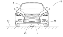
- FIG. 3 is an explanatory diagram of a driving support system in the first embodiment.
- 1 is a front view showing an RFID tag in Embodiment 1.
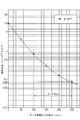
- FIG. 3 is a graph showing the magnetic field distribution in the vertical direction of the magnetic marker in the first embodiment.
- FIG. 3 is a block diagram showing an electrical configuration of the magnetic sensor in the first embodiment.
- FIG. 3 is a block diagram illustrating an electrical configuration of an RFID tag and a tag reader in the first embodiment.
- the flowchart which shows the flow of operation
- the traveling path on which the magnetic marker is laid may be a public road or a passage in a site such as a shopping center. Furthermore, it may be a passage of a self-propelled multilevel parking lot or a self-propelled underground parking lot in a building such as a shopping center.
- the information providing unit may be a wireless tag held by the magnetic marker.
- information can be provided to the vehicle side by wireless communication.
- wireless communication even if snow or dirt adheres to the surface side of the magnetic marker, the influence is relatively small, and information can be transmitted.
- the vehicle-side information acquisition unit may be provided with a function of demodulating information by receiving radio waves transmitted from the magnetic marker.
- the magnetic marker holds the wireless tag
- a sheet-like wireless tag is disposed on the front surface side or the back surface side of the magnetic marker, or disposed on the side surface side of the magnetic marker.
- the wireless tag may be partially embedded in the magnetic marker, while the wireless antenna may be disposed on the front side, back side, or side surface of the magnetic marker.
- the wireless tag may be entirely embedded and held in the magnetic marker.
- the surface side of the magnetic marker is the side facing upward when laid, and the back side of the magnetic marker is the side facing the road surface of the traveling path when laid.
- the wireless tag may be a magnetic marker that is a wireless tag using a frequency band of 710 to 960 MHz. If the wireless tag uses this frequency band, small and robust wireless communication can be realized.
- the magnetism generating unit may have a magnet molded with magnetic powder as a magnetism source.
- a magnet formed from the magnetic powder has a high electrical internal resistance, so that eddy currents can be suppressed and power can be transmitted efficiently.
- a bonded magnet formed by kneading magnetic powder in a binder made of a polymer material such as rubber or plastic is used as the magnetic generating part, high frequency loss can be reduced, so a high frequency band is used. The compatibility with the wireless tag is good.
- the information providing unit may be a pattern that is formed on the surface of the magnetic marker and that can be read imagewise.
- an image-readable pattern for example, an image code such as a barcode or QR code (registered trademark), a color type, a color painting pattern, a texture (pattern), a character, There are various patterns such as symbols that can be identified in an image.
- the information acquisition unit on the vehicle side may be provided with a function of image-capturing a pattern formed on the surface of the magnetic marker and image-reading information represented by the pattern.
- the use of the information acquired from the magnetic marker may be driving assistance by presenting the information or processing information to the driver, or driving the vehicle by using the information.
- a device for presenting information or the like to the driver for example, there are devices such as a display, a speaker, an alarm, a buzzer, and a vibrator.
- a device for controlling the vehicle for example, there are a device for realizing automatic braking, a device for realizing automatic steering, a device for automatically controlling an engine throttle, and the like.
- the information provided by the information providing unit of the magnetic marker may be position information indicating the laying position of the magnetic marker.
- position information indicating the laying position of the magnetic marker can be acquired on the vehicle side.
- This position information is effective information that can be used for capturing the position of the vehicle on the vehicle side.
- the vehicle may include an inter-vehicle communication device for transmitting / receiving information on the position of the vehicle based on the position information acquired from the magnetic marker to / from another vehicle.
- the vehicle can grasp the positional relationship with other vehicles in the vicinity. If the positional relationship with other vehicles can be grasped, the reliability of the control can be increased and the safety can be improved in driving assistance such as automatic brake control. Moreover, if it is driving assistance, such as a warning, the warning regarding the behavior of the vehicle which a driver
- Example 1 This example is an example related to the driving support system 1S that uses the magnetic marker 1. The contents will be described with reference to FIGS.
- a vehicle driving support system 1S illustrated in FIG. 1 is a system in which a magnetic marker 1 laid on a road surface 53 of a traveling path of a vehicle 5 and a vehicle 5 including an in-vehicle unit 2A including a magnetic sensor 2 and the like. It is.
- An output signal of the in-vehicle unit 2A attached to the vehicle body floor 50 that hits the bottom surface of the vehicle 5 is input to, for example, an ECU (not shown) on the vehicle 5 side.
- the output signal of the in-vehicle unit 2A can be used for various driving support such as automatic steering control for lane keeping, lane departure warning, route navigation, traffic information display, warning, and automatic driving. .
- the magnetic marker 1 has a flat circular shape with a diameter of 100 mm and a maximum thickness of about 2.0 mm, and is a marker that can be adhesively bonded to the road surface 53.
- a sheet-like RFID tag (Radio Frequency IDentification, wireless tag) 15 is laminated on the surface side.
- the magnetic marker 1 of this example including the RFID tag 15 can provide various types of information to the vehicle 5 side without depending on the magnetic method.
- the magnetic marker 1 is a marker in which the front and back sides of a flat magnet sheet 11 having a diameter of 100 mm and a thickness of 1 mm are covered with a resin mold 12.
- the magnet sheet 11 which is an example of a magnetism generating unit is an isotropic ferrite rubber magnet sheet having a maximum energy product (BHmax) of 6.4 kJ / m 3 .
- the magnet sheet 11 is a bonded magnet formed into a sheet shape by mixing a raw material, which is a magnetic powder of iron oxide, with rubber as a binder.
- the sheet-like RFID tag 15 having a thickness of 0.5 mm is laminated on the surface of the magnet sheet 11.
- the resin mold 12 on the front surface side covers the front surface side of the magnet sheet 11 on which the RFID tags 15 are stacked.
- the thickness of the resin mold 12 on the front surface side of the magnetic marker 1 is 0.3 mm, and the thickness on the back surface side corresponding to the construction surface of the magnetic marker 1 is 0.2 mm.
- the portion where the RFID tag 15 is disposed has a maximum thickness, and the maximum thickness including the thickness of the resin mold 12 is 2.0 mm.
- a sheet having a diameter of 100 mm and a thickness of 0.5 to 1.0 mm provided with a rectangular arrangement hole corresponding to the RFID tag 15 is laminated on the surface of the magnet sheet 11, and the RFID tag 15 is positioned in the arrangement hole. It is also good. In this case, the thickness of the portion where the RFID tag 15 is disposed can be equal to or thinner than other portions. Thereby, when the magnetic marker 1 is stepped on the tire etc. of the vehicle 5, the load which acts on the RFID tag 15 can be suppressed.
- the construction of the magnetic marker 1 on the road surface 53 is performed by, for example, bonding and fixing with an adhesive.
- a resin mold may be applied to the outer peripheral side surface of the magnetic marker 1.
- it is also possible to form a resin mold reinforced with glass fibers by laminating a glass cloth or the like on the surface of the magnet sheet 11 on which the RFID tag 15 is laminated, and impregnating the glass cloth with a resin.
- the RFID tag 15 that is an example of an information providing unit is an electronic component in which an IC chip 157 is mounted on the surface of a tag sheet 150 that is a sheet-like member, as shown in FIG.
- the RFID tag 15 is configured to operate with power supplied from the outside by wireless transmission, and to transmit information stored in the IC chip 157 wirelessly.
- the RFID tag 15 of this example is a wireless tag using the 900 MHz band.
- the RFID tag 15 can be easily downsized, and robust radio communication can be realized because of high radio wave permeability.
- seat 11 which is a bond magnet is equipped with the characteristic that there are few high frequency losses. Therefore, the magnet sheet 11 is less likely to attenuate the 900 MHz band radio wave transmitted by the RFID tag 15 and is less likely to hinder the robustness of wireless communication.
- the tag sheet 150 is a sheet-like member cut out from the PET film.
- a loop coil pattern 151 and an antenna pattern 153 which are printed patterns of conductive ink such as silver paste, are formed.
- Each of the loop coil pattern 151 and the antenna pattern 153 has a substantially annular shape having a notch at one place.
- a chip placement area (not shown) for placing the IC chip 157 is formed in the notched portion.
- the loop coil pattern 151 is a pattern that forms the power receiving coil 152.
- An exciting current is generated in the loop coil pattern 151 by electromagnetic induction from the outside.
- the antenna pattern 153 is a pattern that forms the transmission antenna 154 that wirelessly transmits information.
- the power receiving coil 152 formed by the loop coil pattern 151 and the transmission antenna 154 formed by the antenna pattern 153 both have sensitivity in the vertical direction of the formation surface. This sensitivity specification is suitable for communication with the in-vehicle unit 2 ⁇ / b> A attached to the vehicle body floor 50 of the vehicle 5.
- As the conductive ink for printing the patterns 151 and 153 graphite paste, silver chloride paste, copper paste, nickel paste, etc. can be used in addition to silver paste. Further, the patterns 151 and 153 can be formed by copper etching or the like.
- the IC chip 157 is an electronic component in which a semiconductor element 158 including a ROM and a RAM as memory means is mounted on the surface of a sheet-like base material 159.
- the RFID tag 15 is produced by attaching the IC chip 157 to the surface of the tag sheet 150 described above.
- various bonding methods such as ultrasonic bonding and caulking bonding can be employed in addition to the conductive adhesive.
- the electrical configuration of the RFID tag 15 will be described later with reference to the block diagram of FIG.
- the tag sheet 150 of the RFID tag 15 and the substrate 159 of the IC chip 157 a resin film such as polyethylene (PE), polyethylene terephthalate (PET), polypropylene (PP), paper, or the like can be used.
- the IC chip 157 may be a semiconductor element itself or a chip obtained by packaging a semiconductor element with a plastic resin or the like.
- Table 1 shows part of the shape specifications and magnetic specifications of the magnet sheet 11 provided in the magnetic marker 1 of this example.
- the magnetic field distribution in which the magnetic marker 1 acts in the vertical direction is as shown in FIG.
- the figure is a semilogarithmic graph showing a simulation result by an axisymmetric three-dimensional static magnetic field analysis using a finite element method.
- a simulation program in which the accuracy of the simulation has been confirmed in advance by a demonstration experiment is used. Furthermore, for some of the data shown in the figure, it has been confirmed by simulation that the simulation values are correct.
- the logarithmic scale of the magnetic flux density acting in the vertical direction is set on the vertical axis, and the vertical height (height from the marker surface) with respect to the surface of the magnetic marker 1 is set on the horizontal axis. is doing.
- Gs surface magnetic flux density
- a magnetic flux density of 8 microtesla or more is ensured in a range of 100 to 250 mm assumed as a mounting height of the magnetic sensor 2.
- the vehicle 5 includes an in-vehicle unit 2A (FIG. 1) including the magnetic sensor 2 in FIG. 5 that magnetically detects the magnetic marker 1 and the tag reader 3 in FIG. 6 that acquires information from the magnetic marker 1.
- the in-vehicle unit 2A is attached to the vehicle body floor 50 that forms the bottom surface of the vehicle so that the magnetic marker 1 laid on the road surface 53 can be detected.
- the mounting height of the in-vehicle unit 2A is in the range of 100 to 250 mm, although it varies depending on the vehicle type.
- the magnetic sensor 2 and the tag reader 3 constituting the in-vehicle unit 2A will be described in order.
- the magnetic sensor 2 that is an example of a magnetic detection unit is a one-chip MI (Magnet Impedance) sensor in which an MI element 21 and a drive circuit are integrated.
- the MI element 21 is an element including an amorphous wire (an example of a magnetic sensitive body) 211 made of a CoFeSiB alloy having substantially zero magnetostriction, and a pickup coil 213 wound around the amorphous wire 211.
- the magnetic sensor 2 detects magnetism acting on the amorphous wire 211 that is a magnetosensitive body by measuring an induced voltage of the pickup coil 213 when a pulse current is applied to the amorphous wire 211.
- the drive circuit includes a pulse circuit 23 that supplies a pulse current to the amorphous wire 211, and a signal processing circuit 25 that samples and outputs the induced voltage of the pickup coil 213 at a predetermined timing.
- the pulse circuit 23 is a circuit including a pulse generator 231 that generates a pulse signal that is a source of a pulse current.
- the signal processing circuit 25 is a circuit that takes out an induced voltage of the pickup coil 213 through a synchronous detection 251 that is opened and closed in conjunction with a pulse signal, and amplifies it with a predetermined amplification factor by an amplifier 253.
- the signal amplified by the signal processing circuit 25 is output to the outside as a sensor signal.
- the magnetic sensor 2 is a highly sensitive sensor having a magnetic flux density measurement range of ⁇ 0.6 millitesla and a magnetic flux resolution within the measurement range of 0.02 microtesla. Such high sensitivity is realized by the MI element 21 utilizing the MI effect that the impedance of the amorphous wire 211 changes sensitively according to the external magnetic field. According to the magnetic sensor 2 having a magnetic flux resolution of 0.02 micro Tesla (see Table 2), the magnetic force of at least a magnetic flux density of 8 micro Tesla (see FIG. 4) acts at an installation height of 100 to 250 mm. The magnetic marker 1 to be detected can be detected with high certainty. Furthermore, the magnetic sensor 2 can perform high-speed sampling at a cycle of 3 kHz, and is compatible with high-speed driving of the vehicle.
- the tag reader 3 that is an example of the information acquisition unit includes a power supply unit 31 that supplies power to the RFID tag 15 included in the magnetic marker 1, and information acquisition that acquires information wirelessly transmitted by the RFID tag 15. Part 33.
- the power supply unit 31 is an electronic circuit that supplies current to the loop coil 310 to generate a magnetic field and transmits power by electromagnetic induction.
- the information acquisition unit 33 is an electronic circuit that receives a radio wave transmitted by the RFID tag 15 using the loop antenna 330 and extracts information by demodulation.
- the tag reader 3 transmits electric power by generating an exciting current in the power receiving coil 152 on the RFID tag 15 side by electromagnetic induction by the magnetic field generated by the loop coil 310, and stores the power in the power receiving unit 155 on the RFID tag 15 side.
- the wireless transmission unit 156 operates upon receiving power supply from the power reception unit 155, and transmits various types of information to the vehicle 5 side via the transmission antenna 154.
- it is a dedicated work vehicle on which a reader / writer having a data writing function is mounted, new information can be written to the RAM, data can be rewritten, and the like.
- the operation of the in-vehicle unit 2A in the driving support system 1S will be described with reference to the flowchart of FIG. While the vehicle 5 is traveling, the detection process of the magnetic marker 1 is repeatedly executed using the magnetic sensor 2 of the in-vehicle unit 2A (S101).
- the in-vehicle unit 2A causes the tag reader 3 to perform power transmission, thereby supplying operating power to the RFID tag 15 of the magnetic marker 1 (S103).
- the in-vehicle unit 2A causes the tag reader 3 to start reception / demodulation processing in synchronization with wireless transmission started in accordance with the operation of the RFID tag 15 (S104), and acquires transmission information from the RFID tag 15.
- the information provided to the vehicle 5 by the RFID tag 15 included in the magnetic marker 1 can be exemplified by the following (1) position information, (2) height information, (3) traffic information, and the like.
- information such as the presence / absence of the magnetic marker 1 and the lateral displacement amount of the vehicle 5 when passing through the magnetic marker 1 can be acquired. It can be applied to various driving assistances such as departure warning, automatic steering, lane departure avoidance control and automatic driving.
- Two-dimensional position information If two-dimensional position information is provided to the vehicle 5 side, accurate position information can be acquired on the vehicle 5 side without using positioning means such as GPS (Global Positioning System).
- GPS Global Positioning System
- a navigation system can be realized.
- the vehicle position is estimated by autonomous navigation using measured values such as the vehicle speed and the yaw rate, and every time the vehicle passes the magnetic marker 1. It is good to get the exact position.
- a combination with a navigation system having positioning means such as GPS is also effective. If a magnetic marker 1 that can provide position information is installed in places where GPS radio waves cannot be received or are likely to be unstable, such as tunnels and valleys of buildings, navigation with a poor GPS radio wave can be backed up. The position acquisition accuracy by the system can be improved.
- the magnetic marker 1 may be laid in a passage such as a self-propelled multilevel parking lot such as a shopping center, and height information such as the number of floors may be provided to the vehicle 5 side.
- height information such as the number of floors
- GPS or the like it is not easy to specify the number of floors in a building. If the number of floors where the vehicle is located is unknown, it is difficult to provide route guidance to the vacant frames with high accuracy even if vacant frame information with designated floor numbers is provided from the infrastructure side. If there is provision of height information that can specify the number of floors, highly accurate route guidance to empty frames in a self-propelled multilevel parking lot can be realized.
- Traffic information such as information on intersections, information on branches, and information on junctions
- the magnetic marker 1 may be installed at a characteristic point on a road (traveling road) such as an intersection, a branch road, or a combined flow path, and information on the corresponding road shape type may be provided from the magnetic marker 1 side.
- driving assistance using traffic information there are various driving assistance controls such as a display for alerting the driver, presentation of traffic information by an alarm sound, etc., and brake control and steering control. For example, if the distance between the stop line at the intersection and the magnetic marker 1 is defined, the brake control for stopping at the stop line can be executed with high accuracy.
- the driving support control for branching on the branch path can be executed with high accuracy.
- Information on the distance between the intersection or branch path and the magnetic marker 1 may be included in the transmission information from the RFID tag 15.
- the magnetic marker 1 constituting the driving support system 1S of this example includes the RFID tag 15 as an information providing unit.
- the magnetic marker 1 On the vehicle 5 side, by detecting the magnetic marker 1 by a magnetic method, it is possible to detect the presence / absence of the magnetic marker 1 and the amount of lateral displacement of the vehicle 5 in the vehicle width direction, and obtain information useful for driving support from the magnetic marker 1. it can. If it is the driving support system 1S which lays the high-functional magnetic marker 1 provided with the RFID tag 15 on the travel path, various driving support including automatic driving can be realized by using the magnetic marker 1.
- the magnetic flux density Gs on the surface is suppressed to 1 millitesla while ensuring the magnetic characteristics detectable by the magnetic sensor 2.
- the magnetic flux density of 1 millitesla is even smaller than, for example, 1/10 of the magnetic flux density of about 20 to 40 millitesla on the surface of a magnet sheet attached to a whiteboard, a refrigerator door, or the like.
- the magnetic marker 1 has a very weak magnetic force even compared to these office or household magnet sheets.
- the magnetic field generated by the magnetic marker 1 is extremely weak, the efficiency of electromagnetic induction when transmitting power from the vehicle 5 side can be increased, and the reliability and efficiency of power transmission can be ensured.
- the RFID tag 15 and the tag reader 3 employ loop-shaped magnetic field antennas that detect magnetic field components and the like as the antennas 154 and 330 for transmitting and receiving information. If the peripheral magnetic field is large, information transmission / reception may be affected. However, if the magnetic field generated by the magnetic marker 1 is weak, the reliability of wireless communication is less likely to be impaired.
- an isotropic ferrite rubber magnet which is a bonded magnet formed by mixing rubber as a binder with magnetic powder of iron oxide, is illustrated as the magnet sheet 11 forming the magnetism generating portion of the magnetic marker 1.
- the magnet of the magnetic marker may be a bonded magnet such as a plastic magnet molded with a mold after the raw material, which is magnetic powder of iron oxide, is mixed with the raw material, plastic, and then melted, and the raw material is baked and hardened.
- a sintered magnet or the like may be used.
- the ferrite magnet forming the magnet sheet 11 has a characteristic that electric resistance is large. Therefore, when electric power is transmitted by electromagnetic induction, there is little possibility that an eddy current is generated on the surface of the magnet sheet 11, and transmission efficiency when electric power is transmitted wirelessly can be ensured. Further, in the magnet sheet 11 which is a bonded magnet obtained by pulverizing a magnet and kneaded into a rubber which is a binder, the pulverized magnets are bonded by a binder which is an insulator, and the electric resistance is very large. Therefore, according to this magnet sheet 11, when the RFID tag 15 performs wireless communication, there is almost no possibility of causing high-frequency loss.
- the RFID tag 15 is disposed so as to be attached to the front surface, back surface, or side surface of the magnet sheet 11 or the magnetic marker 1, the RFID tag 15 is disposed inside the magnet sheet 11 or the magnetic marker 1, or the magnetic marker.
- an RFID tag 15 may be disposed on the lower side of 1.
- a high frequency of 100 kHz or higher can be selected as the carrier frequency for wireless communication by the RFID tag 15. If the carrier frequency is high, the RFID tag can be easily downsized. In particular, in the case of a carrier frequency in the 900 MHz band, for example, since the transparency is high, it is relatively easy to ensure communication stability and the robustness can be improved.
- a bonded magnet with low high-frequency loss such as a rubber magnet or plastic magnet
- a carrier frequency in the 900 MHz band wireless communication robustness and RFID tag size reduction And both.
- a similar effect can be expected if the RFID tag uses a frequency band of 710 to 960 MHz.
- the sensor using the MI element 21 is illustrated as the magnetic sensor 2.
- the magnetic sensor may be any magnetic sensor having a sensitivity capable of detecting the magnetic marker 1 within the range of 100 to 250 mm assumed as the mounting height, and is not limited to a magnetic sensor using the MI element 21. Absent.
- other types of magnetic sensors such as a fluxgate sensor and a TMR sensor can be used.
- a combination of two or more of an MI sensor, a fluxgate sensor, and a TMR sensor can be employed.
- the position of the magnetic sensor installed in the vehicle is at least about 100 mm away from the road surface. As the magnetic sensor, it is necessary to employ a sensor having a performance capable of easily detecting the magnetism generated by the magnetic marker 1 disposed on the road surface.
- the magnetic material and the kind of magnet of the magnet sheet 11 constituting the magnetic marker 1 are not limited to this example. Various types and types of magnetic materials and magnets can be used. It is preferable to selectively determine an appropriate magnetic material and type according to the magnetic specifications and environmental specifications required for the magnetic marker 1.
- the RFID tag 15 and the tag reader 3 may share an antenna for power transmission and an antenna for transmitting or receiving information.
- the RFID tag 15 is provided on the front side of the magnetic marker 1, but the RFID tag 15 may be provided on the back side.
- the RFID tag 15 is positioned on the back side of the magnetic marker 1 body. For example, even when the magnetic marker 1 is stepped on a vehicle tire, since the RFID tag 15 can be protected by the main body of the magnetic marker 1, the configuration for protecting the RFID tag 15 can be simplified.
- RFID tags may be stacked on the surface of the magnetic marker 1 after the resin mold layer is formed. The same applies to the case where an RFID tag is disposed on the back side or side surface of the magnetic marker 1.
- an inter-vehicle communication device that enables mutual communication between the vehicles 5 may be provided in each vehicle 5.
- the vehicles 5 on the road can transmit and receive each other's position information wirelessly. If each vehicle 5 can grasp the positional relationship with other vehicles in the vicinity, the safety and accuracy of vehicle control for driving assistance including automatic driving can be improved.
- the position information of the own vehicle position exchanged between the vehicles may be position information based on the position information provided from the magnetic marker 1. For example, the position information including the movement information by the autonomous navigation after passing through the magnetic marker 1 is set as the own vehicle position, or the position information obtained by correcting the lateral displacement amount of the own vehicle with respect to the magnetic marker 1 It is good to set as a position.
- a sheet-shaped magnetic marker 1 is illustrated as a magnetic marker.
- the shape of the magnetic marker may be a columnar shape such as a circular cross section or a polygonal cross section.
- the combination of the columnar magnetic marker height and outer diameter may be a long and narrow columnar shape whose height dimension is larger than the outer diameter, but it is a short columnar shape whose outer diameter dimension is larger than the height.
- a cylindrical shape having a height of 10 to 20 mm and a diameter of 25 to 30 mm is preferable.
- a ferrite plastic magnet which is a kind of bonded magnet, may be adopted.
- accommodation spaces such as depressions or holes for accommodating the magnetic markers in the road.
- accommodation space it is preferable to secure a large dimension in the depth direction with respect to the height of the magnetic marker.
- the upper end surface of the magnetic marker disposed in the accommodation space is lower than the road surface.
- the magnetic marker may be sealed by filling with a methacrylic resin filler to improve uniformity with the surrounding road surface.
- asphalt may be adopted as the filler.
- a woven or non-woven fabric such as glass fiber, carbon fiber, or cellulose nanofiber may be disposed on the upper end surface side of the magnetic marker.
- the characteristics of the filler can be enhanced by impregnating the woven or non-woven fabric with the filler.
- the size of the woven or non-woven fabric may be smaller than the cross-sectional shape of the storage space, but may be slightly larger than the cross-sectional shape of the storage space. If it is a woven cloth etc. larger than the cross-sectional shape of a storage space, a magnetic marker can be integrally covered with the road surface around a storage space. In this case, the opening portion of the accommodation space can be protected integrally with the surrounding road surface. For example, the dent of the opening part of an accommodation space can be suppressed, and the favorable laying state of a magnetic marker can be maintained long in the operation over a long period of time on a road.
- Example 2 In this example, instead of the magnetic marker of the first embodiment, a magnetic marker 1 in which an image pattern is formed on the surface side is employed.
- the contents will be described with reference to FIGS.
- the magnetic marker 1 in FIG. 8 has the same shape specifications and magnetic specifications as those of the first embodiment, and the surface treatment of a resin mold or the like is also the same.
- the difference is that the RFID tag 15 is not laminated on the surface side, and instead, a code image 18 which is an image-like pattern that is an example of an information providing unit is formed by printing or the like.
- the in-vehicle unit constituting the driving support system of the present example performs information processing from the code image 18 by performing image processing on the image picked up by the camera that images the road surface 53 and the magnetic marker 1 instead of the tag reader of the first embodiment.
- a combination (not shown) with the image ECU to be read is provided as an example of the information acquisition unit.
- a film on which a code image 18 such as a barcode or QR code (registered trademark) is printed is laminated on the surface of the magnet sheet 11, and a transparent resin mold layer is further formed on the surface.
- the camera on the vehicle 5 side is attached with the lens facing downward so that the surface of the magnetic marker 1 laid on the road surface 53 can be imaged.
- the image ECU is configured to capture a captured image of the camera and perform image processing when the magnetic marker 1 can be detected magnetically, to cut out a code image area and to read information represented by the code image 18. ing.
- a code image may be printed directly on the surface of the resin mold that covers the surface side of the magnet sheet 11.
- a transparent protective layer may be provided on the surface side of the code image.
- a code image in which a white portion is convex and a black portion is uneven such as a recess may be formed.
- a black sheet in the code image is covered with a white sheet provided with a hole so that the black color of the magnet sheet 11 can be seen from the outside through the hole, and the code image is displayed in comparison with the white part of the white sheet. It is also good to do.
- a color pattern may be displayed instead of the code image.
- the color pattern include a pattern of a single color, a color coating pattern, and the like. In the case of a single color, it is conceivable to display a safe part in blue, an accident-prone and dangerous part in red, an intersection in red, a combined path in yellow, and a branch path in blue.
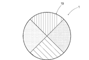
- the color painting pattern for example, the information may be presented by a color painting pattern 19 of four regions divided by angles as shown in FIG. Further, if the amount of information that can be provided by one magnetic marker 1 is not sufficient for the purpose, a combination of two or more magnetic patterns 1 such as two adjacent in the traveling direction of the vehicle 5 is combined. Can also represent one piece of information. Other configurations and operational effects are the same as those in the first embodiment.
- Magnetic Marker 1S Driving Support System 11 Magnet Sheet (Magnetic Generator) 12 Resin mold 15 RFID tag (wireless tag, information provider) 18 Code image (Information provision department) 19 Coloring pattern (information provision department) 2A In-vehicle unit 2 Magnetic sensor (magnetic detection unit) 21 MI element 3 Tag reader (information acquisition unit) 5 Vehicle 50 Body floor (bottom) 53 road surface
Landscapes
- Engineering & Computer Science (AREA)
- Physics & Mathematics (AREA)
- General Physics & Mathematics (AREA)
- Radar, Positioning & Navigation (AREA)
- Remote Sensing (AREA)
- Automation & Control Theory (AREA)
- Aviation & Aerospace Engineering (AREA)
- Life Sciences & Earth Sciences (AREA)
- Atmospheric Sciences (AREA)
- Mechanical Engineering (AREA)
- Transportation (AREA)
- Human Computer Interaction (AREA)
- Traffic Control Systems (AREA)
- Control Of Driving Devices And Active Controlling Of Vehicle (AREA)
- Electromagnetism (AREA)
- Road Signs Or Road Markings (AREA)
Abstract
Description
前記磁気マーカを敷設する走行路は、公共の道路であっても良く、ショッピングセンタなどの敷地内の通路であっても良い。さらに、ショッピングセンタなどの建物内の自走式の立体駐車場や自走式の地下駐車場の通路であっても良い。
この場合には、無線通信により情報を車両側に提供できる。無線通信であれば、前記磁気マーカの表面側に積雪や汚れ等が付着等しても影響が比較的少なく、情報の送信が可能である。なお、車両側の情報取得部には、前記磁気マーカから送信された電波を受信して情報を復調する機能を設けると良い。
この周波数帯域を使用する無線タグであれば、小型かつロバストな無線通信を実現できる。
この場合には、前記磁気マーカを通過する際、その磁気マーカの敷設位置を表す位置情報を車両側で取得できるようになる。この位置情報は、車両側で自車位置の捕捉等に利用できる有効な情報である。
本例は、磁気マーカ1を利用する運転支援システム1Sに関する例である。この内容について、図1~図7を参照して説明する。

磁気検出部の一例をなす磁気センサ2は、図5のブロック図の通り、MI素子21と駆動回路とが一体化された1チップのMI(Magnet Impedance)センサである。MI素子21は、ほぼ零磁歪であるCoFeSiB系合金製のアモルファスワイヤ(感磁体の一例)211と、このアモルファスワイヤ211の周囲に巻回されたピックアップコイル213と、を含む素子である。磁気センサ2は、アモルファスワイヤ211にパルス電流を印加したときのピックアップコイル213の誘起電圧を計測することで、感磁体であるアモルファスワイヤ211に作用する磁気を検出する。

情報取得部の一例をなすタグリーダ3は、図6のごとく、磁気マーカ1が備えるRFIDタグ15に対して電力を供給する電力供給部31と、RFIDタグ15が無線送信する情報を取得する情報取得部33と、を含んで構成されている。電力供給部31は、ループコイル310に電流を供給して磁界を発生させ、電磁誘導により電力を伝送する電子回路である。情報取得部33は、ループアンテナ330を利用してRFIDタグ15が送信する電波を受信し、復調により情報を取り出す電子回路である。
車両5の走行中では、車載ユニット2Aの磁気センサ2を利用して磁気マーカ1の検出処理が繰り返し実行される(S101)。磁気センサ2により磁気マーカ1が検出されると(S102:YES)、車載ユニット2Aは、タグリーダ3に電力伝送を実施させ、これにより磁気マーカ1のRFIDタグ15に動作電力を供給する(S103)。車載ユニット2Aは、RFIDタグ15の動作に応じて開始される無線送信に同期してタグリーダ3に受信・復調処理を開始させ(S104)、RFIDタグ15からの送信情報を取得する。
2次元的な位置情報を車両5側に提供すれば、例えばGPS(Global Positioning System)などの測位手段によらずに正確な位置情報を車両5側で取得でき、ナビゲーションシステムを実現できる。また、車両5の進行方向において隣り合う磁気マーカ1の中間に車両5が位置するときには、車速やヨーレートなどの計測値を利用した自律航法により車両位置を推定し、磁気マーカ1を通過する毎に正確な位置を取得すると良い。
例えば、ショッピングセンタなどの自走式立体駐車場などの通路に磁気マーカ1を敷設しておき、階数などの高さ情報を車両5側に提供することも良い。例えばGPS等では、建物内の階数の特定が容易ではない。車両が所在する階数が不明であれば、仮に階数の指定付きの空き枠情報がインフラ側から提供されても、その空き枠への経路案内を精度高く行うことは難しい。階数を特定可能な高さ情報の提供が有れば、自走式立体駐車場内での空き枠への精度の高い路案内を実現できる。
交差点の情報や、分岐路の情報や、合流路の情報などの交通情報を車両5側に提供することも良い。例えば、交差点や分岐路や合流路など道路(走行路)上の特徴あるポイントに磁気マーカ1を設置し、対応する道路形状の種別の情報を磁気マーカ1側から提供すると良い。交通情報を利用する運転支援としては、運転者に注意を促す表示や警報音等による交通情報の提示や、ブレーキ制御やステアリング制御等の各種の運転支援制御がある。例えば交差点の停止線と磁気マーカ1との距離が規定されていれば、停止線に停止させるためのブレーキ制御を精度高く実行できる。また、例えば分岐路の開始位置と磁気マーカ1との距離が規定されていれば、分岐路で分岐させるための運転支援制御を精度高く実行できる。なお、交差点や分岐路と磁気マーカ1との距離の情報を、RFIDタグ15からの送信情報に含めることも良い。
なお、RFIDタグ15及びタグリーダ3について、電力伝送のためのアンテナと、情報を送信あるいは受信するためのアンテナとを共用することも良い。
本例では、磁気マーカ1の表面側にRFIDタグ15を設けているが、RFIDタグ15を裏面側に設けることも良い。磁気マーカ1を路面に敷設したとき、磁気マーカ1本体の裏側にRFIDタグ15が位置するようになる。例えば磁気マーカ1が車両タイヤに踏まれた場合であっても、磁気マーカ1本体によりRFIDタグ15を保護できるため、RFIDタグ15を保護する構成を簡素にできる。
本例は、実施例1の磁気マーカに代えて、表面側に画像的なパターンが形成された磁気マーカ1を採用した例である。この内容について図8及び図9を参照して説明する。
図8の磁気マーカ1は、形状的な仕様や磁気的な仕様が実施例1と同様であり、樹脂モールド等の表面処理も同様である。相違点は、RFIDタグ15が表面側に積層配置されておらず、代わりとして、情報提供部の一例をなす画像的なパターンであるコード画像18が印刷等により形成されている点にある。また、本例の運転支援システムを構成する車載ユニットは、実施例1のタグリーダに代えて、路面53を撮像するカメラと、磁気マーカ1の撮像画像に画像処理を施してコード画像18から情報を読み取る画像ECUと、の組み合わせ(図示略)を情報取得部の一例として備えている。
車両5側のカメラは、路面53に敷設された磁気マーカ1の表面を撮像できるよう、下方にレンズを向けて取り付けられている。画像ECUは、磁気マーカ1を磁気的に検出できたときにカメラの撮像画像を取り込んで画像処理を施し、コード画像領域の切り出し、及びコード画像18が表す情報の読み取りを実行するように構成されている。
また、例えばコード画像中の黒い部分のみに孔を設けた白色シートを被せて、孔を介して磁石シート11の黒色を外部から見えるようにし、白色シートの白い部分との対比によりコード画像を表示することも良い。
また、1箇所の磁気マーカ1で提供可能な情報量が目的に対して十分ではない場合であれば、車両5の進行方向に隣り合う2個など複数の磁気マーカ1の画像的なパターンを組み合わせて1つの情報を表すこともできる。
なお、その他の構成及び作用効果については実施例1と同様である。
1S 運転支援システム
11 磁石シート(磁気発生部)
12 樹脂モールド
15 RFIDタグ(無線タグ、情報提供部)
18 コード画像(情報提供部)
19 塗り分けパターン(情報提供部)
2A 車載ユニット
2 磁気センサ(磁気検出部)
21 MI素子
3 タグリーダ(情報取得部)
5 車両
50 車体フロア(底面)
53 路面
Claims (10)
- 車両に取り付けられた磁気センサで検出できるように走行路に敷設される磁気マーカであって、
磁界を発生する磁気発生部のほかに、車両側に情報を提供する情報提供部を備えている磁気マーカ。 - 請求項1において、前記情報提供部は、前記磁気マーカに保持された無線タグである磁気マーカ。
- 請求項2において、前記無線タグは、710~960MHzの周波数帯域を使用する無線タグである磁気マーカ。
- 請求項1~3のいずれか1項において、前記磁気発生部は、磁気発生源として磁性粉末を含んで成形された磁石を有している磁気マーカ。
- 請求項1~4のいずれか1項において、前記情報提供部は、前記磁気マーカの表面に形成されて画像的に読み取り可能なパターンである磁気マーカ。
- 車両の運転を支援するための運転支援システムであって、
磁界を発生する磁気発生部のほかに、車両側に情報を提供する情報提供部を備える請求項1~5のいずれか1項に記載の磁気マーカが、車両の走行路に敷設され、
車両は、前記磁気マーカを磁気的に検出する磁気検出部のほか、前記磁気マーカの情報提供部が提供する情報を取得する情報取得部を備えている運転支援システム。 - 請求項6において、前記車両は、前記磁気マーカから取得した情報を運転者に提示することで運転を支援する装置を備えている運転支援システム。
- 請求項6又は7において、前記車両は、前記磁気マーカから取得した情報を利用して車両を制御する装置を備えている運転支援システム。
- 請求項6~8のいずれか1項において、前記磁気マーカの情報提供部が提供する情報は、当該磁気マーカの敷設位置を表す位置情報である運転支援システム。
- 請求項9において、前記車両は、前記磁気マーカから取得した位置情報に基づく自車位置の情報を他の車両との間で送受信するための車々間通信装置を備えている運転支援システム。
Priority Applications (5)
| Application Number | Priority Date | Filing Date | Title |
|---|---|---|---|
| US16/097,487 US11921516B2 (en) | 2016-04-28 | 2017-03-30 | Magnetic marker and driving assistance system |
| JP2018514209A JP6544486B2 (ja) | 2016-04-28 | 2017-03-30 | 磁気マーカ及び運転支援システム |
| SG11201809407QA SG11201809407QA (en) | 2016-04-28 | 2017-03-30 | Magnetic marker and driving assistance system |
| EP17789168.6A EP3451309A4 (en) | 2016-04-28 | 2017-03-30 | MAGNETIC MARKER AND FAHRASSISTENZSYSTEM |
| CN201780025324.2A CN109074731B (zh) | 2016-04-28 | 2017-03-30 | 磁性标识器及驾驶支援系统 |
Applications Claiming Priority (2)
| Application Number | Priority Date | Filing Date | Title |
|---|---|---|---|
| JP2016090606 | 2016-04-28 | ||
| JP2016-090606 | 2016-04-28 |
Publications (1)
| Publication Number | Publication Date |
|---|---|
| WO2017187879A1 true WO2017187879A1 (ja) | 2017-11-02 |
Family
ID=60160410
Family Applications (1)
| Application Number | Title | Priority Date | Filing Date |
|---|---|---|---|
| PCT/JP2017/013341 Ceased WO2017187879A1 (ja) | 2016-04-28 | 2017-03-30 | 磁気マーカ及び運転支援システム |
Country Status (6)
| Country | Link |
|---|---|
| US (1) | US11921516B2 (ja) |
| EP (1) | EP3451309A4 (ja) |
| JP (1) | JP6544486B2 (ja) |
| CN (1) | CN109074731B (ja) |
| SG (1) | SG11201809407QA (ja) |
| WO (1) | WO2017187879A1 (ja) |
Cited By (17)
| Publication number | Priority date | Publication date | Assignee | Title |
|---|---|---|---|---|
| CN109409146A (zh) * | 2018-09-27 | 2019-03-01 | 北京计算机技术及应用研究所 | 一种利用射频识别标记道路的方法和系统 |
| WO2019124196A1 (ja) * | 2017-12-20 | 2019-06-27 | 愛知製鋼株式会社 | 磁気マーカ及び磁気マーカシステム |
| WO2019156194A1 (ja) * | 2018-02-12 | 2019-08-15 | 愛知製鋼株式会社 | 車両用システム |
| JP2019194801A (ja) * | 2018-05-02 | 2019-11-07 | 愛知製鋼株式会社 | 自動駐車システム |
| WO2019239824A1 (ja) | 2018-06-11 | 2019-12-19 | 愛知製鋼株式会社 | 磁気マーカ |
| JP2020056740A (ja) * | 2018-10-04 | 2020-04-09 | 三菱電機株式会社 | 位置補正システム、車載機、位置補正方法、および位置補正プログラム |
| CN111307154A (zh) * | 2020-02-27 | 2020-06-19 | 南京大学 | 一种基于磁铁阵列扫描的室内行人追踪系统及其工作方法 |
| WO2020138465A1 (ja) * | 2018-12-28 | 2020-07-02 | 愛知製鋼株式会社 | 車両及び車両用の診断システム |
| JPWO2020138460A1 (ja) * | 2018-12-28 | 2020-07-02 | ||
| WO2020262220A1 (ja) * | 2019-06-24 | 2020-12-30 | 愛知製鋼株式会社 | 磁気マーカ及び磁気マーカの利用方法 |
| WO2020262221A1 (ja) * | 2019-06-24 | 2020-12-30 | 愛知製鋼株式会社 | マーカ保持体およびマーカ敷設方法 |
| US11236476B2 (en) | 2018-06-11 | 2022-02-01 | Aichi Steel Corporation | Magnetic marker installation method |
| WO2022034849A1 (ja) * | 2020-08-08 | 2022-02-17 | 愛知製鋼株式会社 | 運行システム及び運行システムの制御方法 |
| US11294090B2 (en) * | 2017-03-28 | 2022-04-05 | Aichi Steel Corporation | Marker detection system and marker detection method |
| JP2022147025A (ja) * | 2021-03-23 | 2022-10-06 | 本田技研工業株式会社 | 車両制御装置 |
| WO2023223706A1 (ja) * | 2022-05-16 | 2023-11-23 | 株式会社 Integral Geometry Science | 自動運転制御システム及び自動運転制御方法 |
| JP7560749B2 (ja) | 2019-11-26 | 2024-10-03 | 愛知製鋼株式会社 | 磁気マーカ及び磁気マーカの作製方法 |
Families Citing this family (9)
| Publication number | Priority date | Publication date | Assignee | Title |
|---|---|---|---|---|
| JP6965815B2 (ja) * | 2018-04-12 | 2021-11-10 | 愛知製鋼株式会社 | マーカ検出システム、及びマーカ検出システムの運用方法 |
| JP2019204195A (ja) * | 2018-05-22 | 2019-11-28 | 本田技研工業株式会社 | 搬送台車の誘導路 |
| CN113260544B (zh) * | 2018-12-28 | 2024-11-26 | 爱知制钢株式会社 | 陀螺仪传感器的修正方法 |
| JP7226587B2 (ja) * | 2019-11-26 | 2023-02-21 | 愛知製鋼株式会社 | 磁気マーカ |
| US11505900B2 (en) * | 2020-01-31 | 2022-11-22 | Rupert R. Thomas, Sr. | Elevated roadway quasi-equilibrium support system |
| CN115769224B (zh) * | 2020-06-26 | 2025-09-30 | 爱知制钢株式会社 | 面向车辆的系统 |
| US20230250598A1 (en) * | 2020-06-26 | 2023-08-10 | Aichi Steel Corporation | Marker system and magnetic marker detection method |
| JP7518390B2 (ja) * | 2021-05-12 | 2024-07-18 | 愛知製鋼株式会社 | システム及び磁気マーカの検出方法 |
| US12479469B2 (en) | 2023-11-22 | 2025-11-25 | Automotive Research & Testing Center | Deciding system for moving vehicle on virtual rail and method thereof |
Citations (4)
| Publication number | Priority date | Publication date | Assignee | Title |
|---|---|---|---|---|
| JPH08314540A (ja) * | 1995-03-14 | 1996-11-29 | Toyota Motor Corp | 車両走行誘導システム |
| WO1999026257A1 (en) * | 1997-11-17 | 1999-05-27 | Unitika Ltd. | A magnetic marker |
| JP2007164441A (ja) * | 2005-12-13 | 2007-06-28 | Denso Corp | 移動体方位決定装置、移動体方位決定方法、ナビゲーション装置、および移動可能端末装置 |
| JP2010288394A (ja) * | 2009-06-12 | 2010-12-24 | Toyota Industries Corp | 車両充電システム及び車両 |
Family Cites Families (51)
| Publication number | Priority date | Publication date | Assignee | Title |
|---|---|---|---|---|
| US2196824A (en) * | 1935-08-12 | 1940-04-09 | Gen Electric | Permanent magnet consisting of iron, nickel, and copper |
| FR2666832B1 (fr) * | 1990-09-19 | 1993-05-07 | Boccon Gibod Henry | Procede de signalisation routiere a traitement automatique. |
| DE4232171C2 (de) * | 1992-09-25 | 1996-07-11 | Noell Gmbh | Verfahren und Vorrichtung zur relativen Positionsbestimmung eines fahrerlosen Fahrzeuges |
| AU696195B2 (en) * | 1994-11-17 | 1998-09-03 | Minnesota Mining And Manufacturing Company | Conformable magnetic articles for use with traffic-bearing surfaces |
| JP3191621B2 (ja) | 1995-03-14 | 2001-07-23 | トヨタ自動車株式会社 | 車両走行誘導システム |
| WO1997014850A1 (en) * | 1995-10-18 | 1997-04-24 | Minnesota Mining And Manufacturing Company | Conformable magnetic articles underlaid beneath traffic-bearing surfaces |
| JP3588922B2 (ja) | 1996-07-08 | 2004-11-17 | トヨタ自動車株式会社 | 車両走行誘導システム |
| EP1020707B1 (en) * | 1997-09-29 | 2003-01-15 | Aichi Steel Works, Ltd. | Magnetic apparatus for detecting position of vehicle |
| JP2000105608A (ja) * | 1998-09-29 | 2000-04-11 | Aichi Steel Works Ltd | 磁気マーカ |
| JP2000309912A (ja) * | 1999-04-27 | 2000-11-07 | Hazama Gumi Ltd | 磁気情報が入力されたブロック、及び製造方法 |
| US6728629B2 (en) * | 2000-11-24 | 2004-04-27 | National Institute For Land And Infrastructure Management, Ministry Of Land, Infrastructure And Transport | On-road reference point positional data delivery device |
| JP2002294085A (ja) * | 2001-03-30 | 2002-10-09 | Dainippon Ink & Chem Inc | 舗装道路埋込型情報送受信装置 |
| JP2003099125A (ja) * | 2001-09-26 | 2003-04-04 | Matsushita Electric Ind Co Ltd | 電磁波マーカと電磁波マーカシステム |
| GB2383983B (en) | 2002-01-11 | 2005-08-17 | Roger Aylward | Route navigation, guidance & control - automated vehicle steering & safety braking |
| JP2004327669A (ja) * | 2003-04-24 | 2004-11-18 | Dowa Mining Co Ltd | ボンド磁石およびボンド磁石用フェライト磁性粉 |
| JP2005202478A (ja) | 2004-01-13 | 2005-07-28 | Denso Corp | 車両用自動走行システム |
| US7592889B2 (en) * | 2004-04-20 | 2009-09-22 | Aichi Steel Corporation | Anisotropic bond magnet for four-magnetic-pole motor, motor using the same, device for orientation processing of anisotropic bond magnet for four-magnetic-pole motor |
| US7253716B2 (en) * | 2004-08-17 | 2007-08-07 | Tagent Corporation | Trackable pills with electronic ID tags |
| US7378971B2 (en) * | 2004-10-01 | 2008-05-27 | Hitachi America, Ltd. | Radio frequency identification tags for digital storage discs |
| JP2007013862A (ja) * | 2005-07-04 | 2007-01-18 | Hitachi Metals Ltd | アンテナ及びこれを用いた電波時計、キーレスエントリーシステム、rfidシステム |
| JP2007280314A (ja) * | 2006-04-12 | 2007-10-25 | Mate Co Ltd | Rfidタグ |
| CN101071526A (zh) * | 2006-05-08 | 2007-11-14 | 林贵生 | 交互式智能道钉及其路网信息系统 |
| JP2008059085A (ja) | 2006-08-29 | 2008-03-13 | Nippon Sheet Glass Co Ltd | 情報管理タグ |
| EP3112802B1 (en) * | 2007-02-16 | 2019-10-09 | Mitsubishi Electric Corporation | Road feature measurement apparatus and road feature measuring method |
| DE102007022065A1 (de) * | 2007-05-11 | 2008-11-27 | Identec Solutions Ag | Verfahren zum Betrieb eines RFID-Tags mit genauer Lokalisierung |
| JP5096862B2 (ja) * | 2007-10-09 | 2012-12-12 | 株式会社リプロ | 標示具 |
| JP4720845B2 (ja) | 2008-04-09 | 2011-07-13 | ブラザー工業株式会社 | 物品管理システム、携帯型無線タグ通信装置 |
| KR101518506B1 (ko) * | 2008-05-26 | 2015-05-07 | 주식회사 포스코 | 자동운행차량시스템의 합류제어방법과 합류제어시스템 |
| CN201302763Y (zh) * | 2008-11-05 | 2009-09-02 | 交通部公路科学研究所 | 磁道钉编码容错装置 |
| BRPI1006814A2 (pt) * | 2009-01-17 | 2016-04-12 | Boomerang Systems Inc | conjunto de antenas de posicionamento de deslocamento variável para a orientação potenciada de veículos guiados automaticamente (agvs) |
| CA2762492C (en) * | 2009-05-22 | 2016-06-14 | Berntsen International, Inc. | System, method and monument for land surveying |
| CN101866017B (zh) * | 2010-06-13 | 2012-07-25 | 交通运输部公路科学研究所 | 基于移位循环唯一码的交通车辆磁定位方法 |
| DE102011018615B4 (de) * | 2011-04-21 | 2022-12-01 | Sew-Eurodrive Gmbh & Co Kg | System, insbesondere Anlage, mit auf einem Boden verfahrbaren Fahrzeug |
| US8078349B1 (en) * | 2011-05-11 | 2011-12-13 | Google Inc. | Transitioning a mixed-mode vehicle to autonomous mode |
| US9245158B2 (en) * | 2012-04-05 | 2016-01-26 | Ricoh Co., Ltd. | Low power radio frequency communication |
| US20130278441A1 (en) | 2012-04-24 | 2013-10-24 | Zetta Research and Development, LLC - ForC Series | Vehicle proxying |
| CN102890510B (zh) * | 2012-10-18 | 2014-12-10 | 江苏物联网研究发展中心 | 基于rfid的港口无人运输车辆智能导航云系统 |
| CN103268116B (zh) * | 2013-04-17 | 2015-02-18 | 无锡普智联科高新技术有限公司 | 基于复合型磁钉校正的agv纠偏控制方法 |
| CN103345847A (zh) * | 2013-07-26 | 2013-10-09 | 武汉理工大学 | 多谱磁道路标线的辨识方法及车载诱导系统 |
| CN103680151B (zh) * | 2013-12-05 | 2016-11-23 | 深圳市悦宏旭昂科技有限公司 | 地磁型路测传感器及其实现方法 |
| CN104793614B (zh) * | 2014-01-16 | 2019-01-04 | 苏州宝时得电动工具有限公司 | 自动行走设备回归引导系统 |
| CN104805780B (zh) * | 2014-01-24 | 2017-09-12 | 北京中交华安科技有限公司 | 太阳能地磁感应路标以及车辆动态尾迹显示系统和方法 |
| US9552912B2 (en) * | 2014-03-03 | 2017-01-24 | Uchiyama Manufacturing Corp. | Magnetic rubber composition, magnetic rubber molded article obtained by crosslinking the same, and magnetic encoder |
| FR3018941B1 (fr) * | 2014-03-21 | 2017-07-07 | Thales Sa | Pilotage de vehicules en convoi |
| CN104153267B (zh) * | 2014-07-31 | 2016-01-20 | 同济大学 | 一种磁导航智能车的交叉路口及通行方法 |
| CN104153603B (zh) * | 2014-07-31 | 2016-04-20 | 同济大学 | 磁导航无人驾驶电动智能车的交通站点及进出站方法 |
| US9892296B2 (en) * | 2014-11-12 | 2018-02-13 | Joseph E. Kovarik | Method and system for autonomous vehicles |
| KR101714145B1 (ko) * | 2015-04-09 | 2017-03-08 | 현대자동차주식회사 | 주변차량 식별 장치 및 그 방법 |
| CN104821093A (zh) * | 2015-05-21 | 2015-08-05 | 济南照岳电子有限公司 | 一种公路高速轨道交通系统及实现方法 |
| CN105180932A (zh) * | 2015-09-16 | 2015-12-23 | 成都四威高科技产业园有限公司 | 一种适合仓储agv的惯性导航方法 |
| KR20160015341A (ko) * | 2016-01-20 | 2016-02-12 | 김평 | 지적측량 표지정보 관리 시스템 및 방법 |
-
2017
- 2017-03-30 US US16/097,487 patent/US11921516B2/en active Active
- 2017-03-30 JP JP2018514209A patent/JP6544486B2/ja active Active
- 2017-03-30 SG SG11201809407QA patent/SG11201809407QA/en unknown
- 2017-03-30 EP EP17789168.6A patent/EP3451309A4/en not_active Ceased
- 2017-03-30 CN CN201780025324.2A patent/CN109074731B/zh active Active
- 2017-03-30 WO PCT/JP2017/013341 patent/WO2017187879A1/ja not_active Ceased
Patent Citations (4)
| Publication number | Priority date | Publication date | Assignee | Title |
|---|---|---|---|---|
| JPH08314540A (ja) * | 1995-03-14 | 1996-11-29 | Toyota Motor Corp | 車両走行誘導システム |
| WO1999026257A1 (en) * | 1997-11-17 | 1999-05-27 | Unitika Ltd. | A magnetic marker |
| JP2007164441A (ja) * | 2005-12-13 | 2007-06-28 | Denso Corp | 移動体方位決定装置、移動体方位決定方法、ナビゲーション装置、および移動可能端末装置 |
| JP2010288394A (ja) * | 2009-06-12 | 2010-12-24 | Toyota Industries Corp | 車両充電システム及び車両 |
Non-Patent Citations (1)
| Title |
|---|
| See also references of EP3451309A4 * |
Cited By (49)
| Publication number | Priority date | Publication date | Assignee | Title |
|---|---|---|---|---|
| US11294090B2 (en) * | 2017-03-28 | 2022-04-05 | Aichi Steel Corporation | Marker detection system and marker detection method |
| JP7205494B2 (ja) | 2017-12-20 | 2023-01-17 | 愛知製鋼株式会社 | 磁気マーカ及び磁気マーカシステム |
| WO2019124196A1 (ja) * | 2017-12-20 | 2019-06-27 | 愛知製鋼株式会社 | 磁気マーカ及び磁気マーカシステム |
| JPWO2019124196A1 (ja) * | 2017-12-20 | 2021-02-12 | 愛知製鋼株式会社 | 磁気マーカ及び磁気マーカシステム |
| CN111492378A (zh) * | 2017-12-20 | 2020-08-04 | 爱知制钢株式会社 | 磁性标识器以及磁性标识器系统 |
| US11238328B2 (en) | 2017-12-20 | 2022-02-01 | Aichi Steel Corporation | Magnetic marker and magnetic marker system |
| CN111492378B (zh) * | 2017-12-20 | 2024-03-15 | 爱知制钢株式会社 | 磁性标识器以及磁性标识器系统 |
| EP3731149A4 (en) * | 2017-12-20 | 2021-09-01 | Aichi Steel Corporation | MAGNETIC MARKER AND SYSTEM WITH MAGNETIC MARKER |
| WO2019156194A1 (ja) * | 2018-02-12 | 2019-08-15 | 愛知製鋼株式会社 | 車両用システム |
| US11801827B2 (en) | 2018-05-02 | 2023-10-31 | Aichi Steel Corporation | Automatic parking system |
| JP7464870B2 (ja) | 2018-05-02 | 2024-04-10 | 愛知製鋼株式会社 | 自動駐車システム |
| US12221095B2 (en) | 2018-05-02 | 2025-02-11 | Aichi Steel Corporation | Automatic parking system |
| CN112041909A (zh) * | 2018-05-02 | 2020-12-04 | 爱知制钢株式会社 | 自动停车系统 |
| JP2022164690A (ja) * | 2018-05-02 | 2022-10-27 | 愛知製鋼株式会社 | 自動駐車システム |
| JP7155596B2 (ja) | 2018-05-02 | 2022-10-19 | 愛知製鋼株式会社 | 自動駐車システム |
| WO2019211987A1 (ja) * | 2018-05-02 | 2019-11-07 | 愛知製鋼株式会社 | 自動駐車システム |
| JP2019194801A (ja) * | 2018-05-02 | 2019-11-07 | 愛知製鋼株式会社 | 自動駐車システム |
| EP3805992A4 (en) * | 2018-06-11 | 2022-03-16 | Aichi Steel Corporation | Method for constructing magnetic marker |
| US11280053B2 (en) | 2018-06-11 | 2022-03-22 | Aichi Steel Corporation | Magnetic marker |
| EP3816861A4 (en) * | 2018-06-11 | 2022-03-02 | Aichi Steel Corporation | MAGNETIC MARKER |
| US11236476B2 (en) | 2018-06-11 | 2022-02-01 | Aichi Steel Corporation | Magnetic marker installation method |
| WO2019239824A1 (ja) | 2018-06-11 | 2019-12-19 | 愛知製鋼株式会社 | 磁気マーカ |
| CN109409146A (zh) * | 2018-09-27 | 2019-03-01 | 北京计算机技术及应用研究所 | 一种利用射频识别标记道路的方法和系统 |
| JP2020056740A (ja) * | 2018-10-04 | 2020-04-09 | 三菱電機株式会社 | 位置補正システム、車載機、位置補正方法、および位置補正プログラム |
| WO2020138460A1 (ja) * | 2018-12-28 | 2020-07-02 | 愛知製鋼株式会社 | 磁気マーカシステム |
| CN113272751B (zh) * | 2018-12-28 | 2024-09-06 | 爱知制钢株式会社 | 磁性标识器系统 |
| CN113272751A (zh) * | 2018-12-28 | 2021-08-17 | 爱知制钢株式会社 | 磁性标识器系统 |
| CN113227929A (zh) * | 2018-12-28 | 2021-08-06 | 爱知制钢株式会社 | 车辆以及车辆用的诊断系统 |
| US11875675B2 (en) | 2018-12-28 | 2024-01-16 | Aichi Steel Corporation | Vehicle and vehicular diagnostic system |
| JPWO2020138465A1 (ja) * | 2018-12-28 | 2021-11-04 | 愛知製鋼株式会社 | 車両及び車両用の診断システム |
| US11862014B2 (en) | 2018-12-28 | 2024-01-02 | Aichi Steel Corporation | Magnetic marker system |
| CN113227929B (zh) * | 2018-12-28 | 2024-06-14 | 爱知制钢株式会社 | 车辆以及车辆用的诊断系统 |
| JPWO2020138460A1 (ja) * | 2018-12-28 | 2020-07-02 | ||
| JP7445139B2 (ja) | 2018-12-28 | 2024-03-07 | 愛知製鋼株式会社 | 磁気マーカシステム |
| JP7389359B2 (ja) | 2018-12-28 | 2023-11-30 | 愛知製鋼株式会社 | 車両及び車両用の診断システム |
| WO2020138465A1 (ja) * | 2018-12-28 | 2020-07-02 | 愛知製鋼株式会社 | 車両及び車両用の診断システム |
| WO2020262220A1 (ja) * | 2019-06-24 | 2020-12-30 | 愛知製鋼株式会社 | 磁気マーカ及び磁気マーカの利用方法 |
| JP7268498B2 (ja) | 2019-06-24 | 2023-05-08 | 愛知製鋼株式会社 | 磁気マーカ及び磁気マーカの利用方法 |
| WO2020262221A1 (ja) * | 2019-06-24 | 2020-12-30 | 愛知製鋼株式会社 | マーカ保持体およびマーカ敷設方法 |
| JP2021002299A (ja) * | 2019-06-24 | 2021-01-07 | 愛知製鋼株式会社 | 磁気マーカ及び磁気マーカの利用方法 |
| JP7560749B2 (ja) | 2019-11-26 | 2024-10-03 | 愛知製鋼株式会社 | 磁気マーカ及び磁気マーカの作製方法 |
| CN111307154B (zh) * | 2020-02-27 | 2023-02-21 | 南京大学 | 一种基于磁铁阵列扫描的室内行人追踪系统及其工作方法 |
| CN111307154A (zh) * | 2020-02-27 | 2020-06-19 | 南京大学 | 一种基于磁铁阵列扫描的室内行人追踪系统及其工作方法 |
| JP2022031596A (ja) * | 2020-08-08 | 2022-02-21 | 愛知製鋼株式会社 | 運行システム及び運行システムの制御方法 |
| JP7437601B2 (ja) | 2020-08-08 | 2024-02-26 | 愛知製鋼株式会社 | 運行システム及び運行システムの制御方法 |
| WO2022034849A1 (ja) * | 2020-08-08 | 2022-02-17 | 愛知製鋼株式会社 | 運行システム及び運行システムの制御方法 |
| US12246746B2 (en) | 2020-08-08 | 2025-03-11 | Aichi Steel Corporation | Operation system and operation system control method |
| JP2022147025A (ja) * | 2021-03-23 | 2022-10-06 | 本田技研工業株式会社 | 車両制御装置 |
| WO2023223706A1 (ja) * | 2022-05-16 | 2023-11-23 | 株式会社 Integral Geometry Science | 自動運転制御システム及び自動運転制御方法 |
Also Published As
| Publication number | Publication date |
|---|---|
| JPWO2017187879A1 (ja) | 2019-02-28 |
| EP3451309A1 (en) | 2019-03-06 |
| JP6544486B2 (ja) | 2019-07-17 |
| US20190155305A1 (en) | 2019-05-23 |
| US11921516B2 (en) | 2024-03-05 |
| CN109074731A (zh) | 2018-12-21 |
| EP3451309A4 (en) | 2019-07-03 |
| SG11201809407QA (en) | 2018-11-29 |
| CN109074731B (zh) | 2021-08-27 |
Similar Documents
| Publication | Publication Date | Title |
|---|---|---|
| JP6544486B2 (ja) | 磁気マーカ及び運転支援システム | |
| JP6947171B2 (ja) | 運転支援システム | |
| JP7140220B2 (ja) | 磁気マーカ及びマーカシステム | |
| JP6355607B2 (ja) | 磁気マーカ及び磁気マーカ検出システム | |
| JP6733289B2 (ja) | 運転支援システム | |
| JP2018036797A (ja) | 車両用システム及び進路推定方法 | |
| WO2017069089A1 (ja) | 磁気マーカ及び磁気マーカ検出システム | |
| CN117063215A (zh) | 信息取得方法以及车辆用系统 | |
| JP6729534B2 (ja) | 磁気マーカ及び磁気マーカ検出システム |
Legal Events
| Date | Code | Title | Description |
|---|---|---|---|
| ENP | Entry into the national phase |
Ref document number: 2018514209 Country of ref document: JP Kind code of ref document: A |
|
| NENP | Non-entry into the national phase |
Ref country code: DE |
|
| 121 | Ep: the epo has been informed by wipo that ep was designated in this application |
Ref document number: 17789168 Country of ref document: EP Kind code of ref document: A1 |
|
| WWE | Wipo information: entry into national phase |
Ref document number: 2017789168 Country of ref document: EP |
|
| ENP | Entry into the national phase |
Ref document number: 2017789168 Country of ref document: EP Effective date: 20181128 |