WO2017188179A1 - H形鋼の製造方法 - Google Patents
H形鋼の製造方法 Download PDFInfo
- Publication number
- WO2017188179A1 WO2017188179A1 PCT/JP2017/016180 JP2017016180W WO2017188179A1 WO 2017188179 A1 WO2017188179 A1 WO 2017188179A1 JP 2017016180 W JP2017016180 W JP 2017016180W WO 2017188179 A1 WO2017188179 A1 WO 2017188179A1
- Authority
- WO
- WIPO (PCT)
- Prior art keywords
- rolling
- hole
- rolled
- mold
- shaping
- Prior art date
- Legal status (The legal status is an assumption and is not a legal conclusion. Google has not performed a legal analysis and makes no representation as to the accuracy of the status listed.)
- Ceased
Links
Images


Classifications
-
- B—PERFORMING OPERATIONS; TRANSPORTING
- B21—MECHANICAL METAL-WORKING WITHOUT ESSENTIALLY REMOVING MATERIAL; PUNCHING METAL
- B21B—ROLLING OF METAL
- B21B1/00—Metal-rolling methods or mills for making semi-finished products of solid or profiled cross-section; Sequence of operations in milling trains; Layout of rolling-mill plant, e.g. grouping of stands; Succession of passes or of sectional pass alternations
- B21B1/08—Metal-rolling methods or mills for making semi-finished products of solid or profiled cross-section; Sequence of operations in milling trains; Layout of rolling-mill plant, e.g. grouping of stands; Succession of passes or of sectional pass alternations for rolling structural sections, i.e. work of special cross-section, e.g. angle steel
- B21B1/088—H- or I-sections
-
- B—PERFORMING OPERATIONS; TRANSPORTING
- B21—MECHANICAL METAL-WORKING WITHOUT ESSENTIALLY REMOVING MATERIAL; PUNCHING METAL
- B21B—ROLLING OF METAL
- B21B1/00—Metal-rolling methods or mills for making semi-finished products of solid or profiled cross-section; Sequence of operations in milling trains; Layout of rolling-mill plant, e.g. grouping of stands; Succession of passes or of sectional pass alternations
- B21B1/08—Metal-rolling methods or mills for making semi-finished products of solid or profiled cross-section; Sequence of operations in milling trains; Layout of rolling-mill plant, e.g. grouping of stands; Succession of passes or of sectional pass alternations for rolling structural sections, i.e. work of special cross-section, e.g. angle steel
- B21B1/12—Metal-rolling methods or mills for making semi-finished products of solid or profiled cross-section; Sequence of operations in milling trains; Layout of rolling-mill plant, e.g. grouping of stands; Succession of passes or of sectional pass alternations for rolling structural sections, i.e. work of special cross-section, e.g. angle steel in a continuous process, i.e. without reversing stands
Definitions
- the present invention relates to a manufacturing method for manufacturing H-section steel using, for example, a slab having a rectangular cross section as a raw material, and H-section steel products.
- raw materials such as slabs and blooms extracted from a heating furnace are formed into a rough shape material (a so-called dogbone-shaped material to be rolled) by a rough rolling mill, and the above-mentioned by an intermediate universal rolling mill.
- the web of the rough material and the thickness of the flange are reduced, and the flange of the material to be rolled is subjected to width reduction and forging and shaping of the flange of the material to be rolled by an edger rolling mill close to the intermediate universal rolling mill.
- an H-section steel product is modeled by a finishing universal rolling mill.
- a crop portion is formed at the front and rear end portions in the longitudinal direction of the material to be rolled.
- intermediate crop cutting is performed in the middle of a series of rolling processes, and the trouble that the crop portion is clogged in the rolling mill is avoided.
- the weight per unit length of the material to be rolled is large and the product elongation during rolling is short, so the proportion of the crop portion in the total length is large, and the crop portion Growth tends to lead to a decrease in yield. Therefore, the fact is that it is required to reduce the growth of the crop portion as much as possible particularly in the production of large H-shaped steel products.
- the purpose of the present invention is to deeply interrupt the protrusions having an acute tip shape on the end face of the material such as the slab in the rough rolling process using the hole mold when manufacturing the H-section steel, By successively bending the flange portion formed thereby, the occurrence of shape defects in the material to be rolled is suppressed, and the growth of the crop portion, which has been a significant yield loss in the manufacture of large H-section steels in the past, has been reduced.
- An object of the present invention is to provide an H-section steel manufacturing technique capable of efficiently and stably manufacturing an H-section steel product having a larger flange width than conventional ones.
- a method for producing an H-section steel comprising a rough rolling process, an intermediate rolling process, and a finish rolling process
- a rolling mill that performs the rough rolling process includes: Five or more hole molds for rolling and shaping the rolled material are engraved, and one or more passes of the material to be rolled are formed in the plurality of hole molds.
- the first hole mold and the first hole mold are formed.
- a protrusion is formed that interrupts perpendicularly to the width direction of the material to be rolled to form a divided portion at the end of the material to be rolled.
- the final hole type among the plurality of hole types is a flat modeling hole type, and the plurality of hole types Of the material to be rolled in the formation of at least one pass after the second hole mold except the final hole mold.
- the rolling is performed in a state where the surface and the peripheral surface of the hole mold are in contact with each other, and the rolling roll gap with respect to a predetermined section at the rear end in the rolling longitudinal direction of the material to be rolled is at least one pass of rolling shaping in the plurality of hole molds
- a method for producing an H-section steel in which rolling shaping is performed by expanding the shape of the steel sheet in comparison with the rolling roll gaps other than the predetermined section.
- the tip angle of the protrusions formed in the first hole mold and the second hole mold may be 25 ° or more and 40 ° or less.
- the rolling roll gap for the predetermined section at the rear end in the rolling longitudinal direction of the material to be rolled is wider than the rolling roll gap for other than the predetermined section. Roll forming may be performed.
- the rolling roll gap with respect to a predetermined section at the rear end portion in the rolling longitudinal direction of the material to be rolled is other than the predetermined section.
- Rolling shaping may be performed in a manner wider than the rolling roll gap.
- Rolling shaping may be performed by expanding the rolling roll gap for a predetermined section at the rear end in the rolling longitudinal direction as compared with the rolling roll gap for other than the predetermined section.
- the rolling roll gap for the predetermined section at the rear end in the rolling longitudinal direction of the material to be rolled is expanded as compared with the rolling roll gap for other than the predetermined section.
- Roll forming may be performed.
- Rolling shaping may be performed by expanding the rolling roll gap other than the predetermined section.
- the intermediate crop cutting step may be performed only on the web portion of the material to be rolled after the rough rolling step and before the intermediate rolling step.
- the crop-shaped portion formed at the end in the longitudinal direction of the material to be rolled may be removed for the first time.
- the rolling mill that performs the rough rolling process may be provided with a reduction mechanism that changes the roll gap of the perforated roll of the rolling mill.
- an H-section steel product manufactured by the above H-section steel manufacturing method wherein the web height is 1000 mm or more or the flange width is 400 mm or more. H-shaped steel products are provided.
- the end face of the material such as the slab is deeply interrupted by the protrusion portion having an acute tip shape, and thereby formed.
- the flange part sequentially, the occurrence of shape defects in the material to be rolled is suppressed, and the growth of the crop part, which has been a large yield loss in the production of large H-section steels in the past, has been reduced. It becomes possible to efficiently and stably manufacture a wide H-shaped steel product.
- FIG. 1 is an explanatory diagram of an H-section steel production line T including a rolling facility 1 according to the present embodiment.
- a heating furnace 2 a sizing mill 3, a roughing mill 4, an intermediate universal rolling mill 5, and a finishing universal rolling mill 8 are arranged in order from the upstream side on the production line T.
- an edger rolling mill 9 is provided in the vicinity of the intermediate universal rolling mill 5.
- the steel materials in the production line T will be collectively referred to as “rolled material A” for the sake of explanation, and the shape may be appropriately illustrated using broken lines, diagonal lines, etc. in each drawing.
- a rectangular cross-section material for example, a slab 11 extracted from the heating furnace 2 is roughly rolled in a sizing mill 3 and a roughing mill 4.
- intermediate rolling is performed in the intermediate universal rolling mill 5.
- the edger rolling machine 9 reduces the flange tip portion (flange corresponding portion 12) of the material to be rolled as necessary.
- the rolls of the sizing mill 3 and the roughing mill 4 are engraved with so-called flat shaping hole molds for reducing the thickness of the edging hole mold and the web part and forming the shape of the flange part.
- the H-shaped rough profile 13 is formed by reverse rolling of a plurality of passes, and the H-shaped rough profile 13 is formed by using a rolling mill row composed of two rolling mills, the intermediate universal rolling mill 5-edger rolling mill 9. A plurality of passes of reduction are applied, and the intermediate material 14 is formed. Then, the intermediate material 14 is finish-rolled into a product shape in the finish universal rolling mill 8 to produce an H-section steel product 16.
- the slab thickness T of the slab 11 extracted from the heating furnace 2 is in the range of 240 mm or more and 310 mm or less, for example. This is a slab size used when manufacturing a general H-shaped steel product.
- FIG. 1 is schematic explanatory views of the sizing mill 3 for performing the rough rolling process and the hole mold formed in the rough rolling mill 4.
- FIG. 1 the first to fourth hole molds to be described may be all engraved in, for example, the sizing mill 3, and the sizing mill 3 and the roughing mill 4 have five holes of the first to fifth hole molds.
- the hole mold may be engraved separately. That is, the first hole type to the fourth hole type may be engraved over both the sizing mill 3 and the rough rolling mill 4, or may be engraved in either one of the rolling mills.
- modeling is performed in one or a plurality of passes in each of these perforations.
- the number of hole types is not necessarily a five-hole type, and a plurality of five or more hole types may be used. It may be. In other words, any hole configuration suitable for modeling the H-shaped rough member 13 may be used. 2 to 6, the approximate final path shape of the material A to be rolled at the time of shaping in each hole mold is illustrated by a broken line.
- FIG. 2 is a schematic explanatory diagram of the first hole mold K1.
- the first hole mold K1 is engraved in the upper hole roll 20 and the lower hole roll 21 which are a pair of horizontal rolls, and the material A to be rolled is placed in the roll gap between the upper hole roll 20 and the lower hole roll 21. Reduced and shaped. Further, on the peripheral surface of the upper hole type roll 20 (that is, the upper surface of the first hole type K1), a protruding portion 25 that protrudes toward the inside of the hole type is formed. Further, a projection 26 is formed on the peripheral surface of the lower hole roll 21 (that is, the bottom surface of the first hole mold K1) protruding toward the inside of the hole mold.
- projecting portions 25 and 26 have a tapered shape, and the projecting length and other dimensions are equal between the projecting portion 25 and the projecting portion 26.
- the height (projection length) of the protrusions 25 and 26 is h1, and the tip angle is ⁇ 1a.
- the protrusions 25 and 26 are pressed against the upper and lower ends (slab end surfaces) of the material A to be rolled, and interrupts 28 and 29 are formed.
- the tip end angle (also referred to as wedge angle) ⁇ 1a of the protrusions 25 and 26 is preferably, for example, 25 ° or more and 40 ° or less.
- the hole width of the first hole mold K1 is substantially equal to the thickness of the material A to be rolled (that is, the slab thickness). Specifically, by making the hole mold width and the slab thickness the same at the tips of the protrusions 25 and 26 formed in the first hole mold K1, the right and left centering property of the material to be rolled A is suitably secured. Is done. Moreover, by setting it as such a hole-type dimension, as shown in FIG.
- the first holes are formed on the upper and lower ends of the slabs, which are partly in contact with the material A to be rolled, and divided into four elements (parts) by interruptions 28 and 29. It is preferable that no positive reduction is performed on the top and bottom surfaces of the mold K1. This is because the reduction by the top and bottom surfaces of the hole mold causes the material A to be elongated in the longitudinal direction, thereby reducing the generation efficiency of the flange (flange portion 80 described later).
- the protrusions 25 and 26 are pressed against the upper and lower ends (slab end surfaces) of the material A to be rolled, and the reduction in the protrusions 25 and 26 when the interrupts 28 and 29 are formed.
- the amount (wedge tip reduction amount) is sufficiently larger than the reduction amount (slab end surface reduction amount) at the upper and lower ends of the slab, whereby interrupts 28 and 29 are formed.
- FIG. 3 is a schematic explanatory diagram of the second hole type K2.
- mold K2 is engraved by the upper hole type
- a protruding portion 35 that protrudes toward the inside of the hole type is formed.
- a projection 36 that protrudes toward the inside of the hole mold is formed on the peripheral surface of the lower hole roll 31 (that is, the bottom surface of the second hole mold K2).
- These projecting portions 35 and 36 have a tapered shape, and the projecting length and other dimensions are configured to be equal between the projecting portion 35 and the projecting portion 36. It is desirable that the tip end angle of the projections 35 and 36 is a wedge angle ⁇ 1b of 25 ° or more and 40 ° or less.
- the wedge angle ⁇ 1a of the first hole mold K1 is a wedge angle of the second hole mold K2 in the subsequent stage in order to secure the tip end thickness of the flange-corresponding portion, increase the inductivity, and ensure the stability of rolling.
- the angle is preferably the same as ⁇ 1b.
- the height (projection length) h2 of the protrusions 35 and 36 is configured to be higher than the height h1 of the protrusions 25 and 26 of the first hole type K1, and h2> h1.
- the material A to be rolled after the first hole K1 passing material is further shaped.
- the height h2 of the protrusions 35 and 36 formed on the second hole mold K2 is higher than the height h1 of the protrusions 25 and 26 formed on the first hole mold K1, and the material A to be rolled A Similarly, the length of penetration into the upper and lower ends (slab end face) of the second hole mold K2 is longer.
- the penetration depth of the projections 35 and 36 into the material to be rolled A in the second hole mold K2 is the same as the height h2 of the projections 35 and 36. That is, the penetration depth h1 ′ of the protrusions 25 and 26 into the rolled material A in the first hole mold K1, and the penetration depth of the protrusions 35 and 36 into the rolled material A in the second hole mold K2.
- h2 has a relationship of h1 ′ ⁇ h2. Further, an angle ⁇ f formed by the hole top surfaces 30a and 30b and the hole bottom surfaces 31a and 31b facing the upper and lower ends (slab end surfaces) of the material A to be rolled and the inclined surfaces of the protrusions 35 and 36 is shown in FIG. The four locations shown are each configured at about 90 ° (substantially at right angles).
- the intrusion length of the protrusion when pressed against the upper and lower ends (slab end face) of the material A is long, in the second hole type K2, the first hole type K1.
- Modeling is performed so that the interrupts 28 and 29 formed in step 1 are further deepened, and interrupts 38 and 39 are formed.
- the flange piece width at the end of the flange shaping process in the rough rolling process is determined based on the dimensions of the interrupts 38 and 39 formed here.
- the second hole mold K2 is formed by multiple passes, but in the multipass formation, the upper and lower ends (slab end surfaces) of the material A to be rolled and the hole upper surface 30a facing it in the final pass. , 30b and the hole bottom surfaces 31a and 31b are shaped. This is because if the upper and lower ends of the material to be rolled A and the inside of the hole mold are not in contact with each other in the second hole mold K2, the flange equivalent part (the part corresponding to the flange part 80 described later) is asymmetrical. This is because there is a possibility that a shape defect such as being formed will occur, and there is a problem in terms of material permeability.
- FIG. 4 is a schematic explanatory diagram of the third hole type K3.
- the third hole type K3 is engraved in the upper hole type roll 40 and the lower hole type roll 41 which are a pair of horizontal rolls.
- a protrusion 45 that protrudes toward the inside of the hole type is formed.
- a projection 46 is formed on the peripheral surface of the lower hole roll 41 (that is, the bottom surface of the third hole mold K3) protruding toward the inside of the hole mold.
- the protrusions 45 and 46 have a tapered shape, and the protrusion 45 and the protrusion 46 have the same dimensions such as the protrusion length.
- the tip end angle ⁇ 2 of the projections 45 and 46 is configured to be wider than the angle ⁇ 1b, and the penetration depth h3 of the projections 45 and 46 into the material to be rolled A is the penetration depth of the projections 35 and 36.
- the length is shorter than h2 (that is, h3 ⁇ h2).
- This angle ⁇ 2 is preferably 70 ° or more and 110 ° or less, for example.
- an angle ⁇ f formed by the hole top surfaces 40a and 40b and the hole bottom surfaces 41a and 41b facing the upper and lower ends (slab end surfaces) of the material A to be rolled and the inclined surfaces of the protrusions 45 and 46 is shown in FIG.
- the four locations shown are each configured at about 90 ° (substantially at right angles).
- the shaping with the third hole mold K3 shown in FIG. 4 is performed by at least one pass, and at least one of these passes is the upper and lower ends (slab end surface) of the material A to be rolled and the inside of the hole mold (second This is performed in a state in which the top surface and the bottom surface of the three-hole mold K3 are in contact with each other. In a state where the upper and lower end portions (slab end surfaces) of the material A to be rolled are in contact with the inside of the hole mold, it is preferable that the end portions are lightly reduced.
- FIG. 5 is a schematic explanatory diagram of the fourth hole type K4.
- mold K4 is engraved by the upper hole type
- a protrusion 55 is formed that protrudes toward the inside of the hole mold.
- a projection 56 that protrudes toward the inside of the hole mold is formed on the peripheral surface of the lower hole roll 51 (that is, the bottom surface of the fourth hole mold K4).
- These projecting portions 55 and 56 have a tapered shape, and the projecting length and other dimensions are configured to be equal between the projecting portion 55 and the projecting portion 56.
- the tip end angle ⁇ 3 of the projections 55 and 56 is configured to be wider than the angle ⁇ 2, and the penetration depth h4 of the projections 55 and 56 into the rolled material A is the penetration depth of the projections 45 and 46.
- the length is shorter than h3 (that is, h4 ⁇ h3).
- the angle ⁇ f formed by the hole top surfaces 50a and 50b and the hole bottom surfaces 51a and 51b facing the upper and lower ends (slab end surfaces) of the material A to be rolled and the inclined surfaces of the protrusions 55 and 56 is the third angle.
- the four locations shown in FIG. 5 are each configured at about 90 ° (substantially perpendicular).
- the projections 55 and 56 are pressed against each other, they are expanded and interrupts 58 and 59 are generated. That is, in the final pass in modeling with the fourth hole mold K4, the deepest part angle of the interrupts 58 and 59 (hereinafter also referred to as the interrupt angle) is ⁇ 3.
- modeling is performed such that the divided part (part corresponding to the flange portion 80 described later) which is modeled with the formation of the interrupts 48 and 49 in the third hole mold K3 is further bent outward.
- the portions of the upper and lower end portions of the material A to be rolled thus formed are portions corresponding to the flanges of the subsequent H-shaped steel product, and are referred to as flange portions 80 here.
- the modeling with the fourth hole mold K4 shown in FIG. 5 is performed by at least one pass, and at least one of these passes is the upper and lower ends (slab end face) of the material A to be rolled and the inside of the hole mold (fourth hole). This is performed in a state where the upper surface and the bottom surface of the mold K4 are in contact with each other. In a state where the upper and lower end portions (slab end surfaces) of the material A to be rolled are in contact with the inside of the hole mold, it is preferable that the end portions are lightly reduced.
- FIG. 6 is a schematic explanatory view of the fifth hole type K5.
- the fifth hole type K5 includes an upper hole type roll 85 and a lower hole type roll 86 which are a pair of horizontal rolls.
- the material A to be rolled formed up to the fourth hole mold K4 is rotated by 90 ° or 270 °, and until the fourth hole mold K4, the material A of the material to be rolled A is rotated.
- the flange portions 80 located at the upper and lower ends are arranged so as to be on the rolling pitch line.
- the dimension adjustment of the flange width is performed by reducing the web part 82 which is a connection part which connects the two flange parts 80, and the flange front-end
- a so-called dogbone-shaped H-shaped rough shape (H-shaped rough shape 13 shown in FIG. 1) is formed.
- mold K5 reduces the thickness by pressing down the web part 82, it is also called a web thickness reduction hole type
- a multi-pass reverse rolling is performed on the H-shaped rough shaped material 13 formed in this way by using a rolling mill row consisting of two rolling mills, an intermediate universal rolling mill 5-edger rolling mill 9, which is a known rolling mill. Is added to form the intermediate material 14. And the intermediate material 14 is finish-rolled by the finishing universal rolling mill 8 to a product shape, and the H-section steel product 16 is manufactured (refer FIG. 1).
- the upper and lower ends (slab end surfaces) of the material A to be rolled are interrupted using the first hole mold K1 to the fourth hole mold K4 according to the present embodiment, and the left and right parts are divided by the interrupts.
- Forming the H-shaped rough shape 13 without substantially rolling down the upper and lower end surfaces of the material A (slab) to be rolled by forming the flange portion 80 by performing a process of bending the portion left and right. It can be carried out. That is, compared with the conventional rough rolling method in which the end face of the slab is always squeezed, the flange width can be widened to form the H-shaped rough shape 13, and as a result, a final product having a large flange width ( H-shaped steel) can be manufactured.
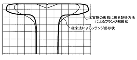
- the shape of the flange portion 80 of the material A to be rolled formed by the first hole mold K1 to the fourth hole mold K4 described above is the conventional manufacturing. Compared to the shape of the flange part before flat hole shaping in the method, the shape is close to the shape of the product flange. This is based on the fact that it adopts a modeling technique that performs the process of bending the segmented part (flange portion 80) that is modeled with interruption without changing the end shape of the material (slab) having a rectangular cross section used as the material. to cause.
- FIG. 11 is an explanatory diagram comparing the shape of the flange portion after edging rolling in the conventional manufacturing method and the shape of the flange portion 80 formed by the first hole mold K1 to the fourth hole mold K4 described above. .
- the shape of the flange portion formed by the method for manufacturing the H-section steel according to the present embodiment is a shape close to the shape of the product flange.
- rolling modeling proceeds without actively rolling down the upper and lower ends (slab end surfaces) of the material A to be rolled in the first hole mold K1 to the fourth hole mold K4.
- the elongation in the longitudinal direction of the material to be rolled A is extremely small.
- the flange portion is actively reduced in the edging rolling stage (corresponding to the rolling shaping in the first hole mold K1 to the fourth hole mold K4 in the present embodiment).
- the flange portion is stretched more than the web portion with respect to the longitudinal direction of the material A to be rolled, and a cut shape (so-called crop shape) is generated at the longitudinal direction end of the material to be rolled, which is called a fish tail.
- a cut shape is generated at the longitudinal direction end of the material to be rolled, which is called a fish tail.
- the web portion has a reduction ratio larger than that of the flange portion, so that a crop shape called a tongue is generated. It was known to end up.
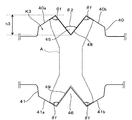
- FIG. 7 is a schematic explanatory diagram regarding the conventional H-shaped steel rolling technology
- (a) is a schematic side view of the conventional edging rolling viewed from the side
- (b) is a conventional flat hole rolling from above.
- FIG. 7 shows the upstream side of rolling.
- the crop-shaped portions 90 and 92 formed in this way have a problem that it is difficult to continue the intermediate rolling because there is a risk of causing a failure of biting into the rolling mill in the subsequent process (intermediate rolling process).
- the cropped portions 90 and 92 shown in FIG. 7B cause the following problems.
- the flange portion of the material A to be rolled is rolled between the horizontal roll side surface and the heel roll during universal rolling, And since a roll is normally a non-driving roll, it tends to bend the to-be-rolled material A on the exit side of the universal rolling mill, and tends to be rolled into the chock.
- the crop-shaped portion 90 having a shape that precedes the flange portion can be connected to the web-flange by inserting the flange portion as it is and changing the web portion when the vertical shift occurs when biting in the rolling mill. This may lead to serious rolling troubles such as tearing the base portion, and dimensional deterioration.
- the crop-shaped portion 92 having a shape leading to the web is a web-flange connecting portion in order to roll the flange portion at the same position when a left-right shift occurs when biting in the rolling mill. It may lead to serious rolling troubles such as tearing the root and dimensional deterioration.
- the crop-shaped part 90 and the crop-shaped part 92 are provided.
- An intermediate crop cutting step for cutting as a cut-off site is provided and supported.
- the present inventors suppress the growth of the crop-shaped portion 90 and the crop-shaped portion 92 formed in the rough rolling process (edging rolling and flat hole rolling). The following findings were obtained.
- a hole roll in which a hole mold is engraved has a configuration in which the roll gap can be freely changed. Further, the roll gap can be changed during the rolling modeling of the material A to be rolled, and the reduction amount can be changed.
- a change in the roll gap is, for example, a rolling mill (sizing) having a reduction mechanism (hydraulic mechanism, not shown in FIGS. 2 to 6) for moving the perforated roll to change the roll gap. It is carried out by using a mill 3 and a rough rolling mill 4).
- Double-pass rolling refers to the longitudinal direction of the material A to be rolled in all the passes that reciprocate the material A when a plurality of reverse rolls are performed on the material A to be rolled in one perforation, for example.
- This is a technique in which the roll gap is expanded only when a section having a predetermined length at the rear end is rolled, and the reduction amount in the hole mold is reduced below the normal reduction amount, or the reduction amount is set to zero.
- the hole mold for performing the double-piece pass rolling may be any one of the first hole mold K1 to the fifth hole mold K5, or may be a plurality of two or more hole molds.
- the crop-shaped portions 90 and 92 called fishtails or tongues are formed and grown at both the rolling biting end and the rolling kicking end, particularly at the rolling kicking end. Although the growth is remarkable, the growth of the cropped portions 90 and 92 can be suppressed by applying the above-mentioned double-piece pass rolling to reduce or reduce the reduction amount in a predetermined section.
- FIG. 8 is a schematic explanatory view when a double piece pass rolling is applied by rolling shaping with the first hole mold K1 in the method for manufacturing the H-section steel according to the present embodiment, and a schematic side view seen from the side. It is.
- the material A to be rolled before rolling shaping in a certain pass left side in the figure
- immediately before completion of rolling shaping in the pass center in the figure
- rolling shaping in the pass After completion right side in the figure
- the rolling modeling is performed with a necessary roll gap (interval between the upper hole roll 20 and the lower hole roll 21).
- the rolling modeling is performed in a state where the roll gap is widened (see the broken line portion in FIG. 8).
- the roll gap may be expanded stepwise so as to gradually reduce the amount of reduction immediately before the end of rolling shaping, or the roll gap may be greatly expanded so that the reduction amount is zero.
- the rolling shaping is performed on the material A to be rolled in a state where the amount of reduction is small (or no amount of reduction) for the predetermined section L compared to other sections. Not so much reduction in the longitudinal direction of the rolled material A is performed. Accordingly, in the edging rolling stage described above with reference to FIG. 7A, the elongation of the flange portion exceeds the elongation of the web portion, and a so-called fish tail is hardly formed. That is, since the reduction amount in the predetermined section L is reduced or becomes zero at the rolling kick end, the growth of the cropped portion 90 as described above is suppressed. For this reason, it becomes possible to omit or simplify the intermediate crop cutting step as described above, and to improve the yield and the efficiency of rolling.
- an edging-rolling shaped hole mold after the first hole mold K1 and / or the third hole mold K3 (the third hole mold in the present embodiment), which may form a defective portion called a so-called fishtail.
- K3 and the fourth hole type K4 it is particularly preferable to apply double-piece pass rolling.
- the double piece pass rolling is necessarily applied to the second hole type K2 which is shaped to further deepen the interruption formed in the first hole type K1. You don't have to.
- the growth of the cropped portion is larger in the pass that is squeezed while the end face of the material to be rolled is in contact with the peripheral face of the hole mold than in the other passes. Accordingly, even in the rolling shaping with the second hole mold K2, in a pass that is squeezed while the end face of the material to be rolled and the peripheral face of the hole mold are in contact with each other, a predetermined section at the rear end in the rolling longitudinal direction of the material to be rolled It is preferable that the rolling roll gap with respect to is expanded compared with the rolling roll gap with respect to other than the predetermined section, and the rolling shaping is performed.
- the end surface of the material to be rolled and the hole peripheral surface may not be in contact with each other.
- the end surface of the material to be rolled and the perforated peripheral surface are in one pass, there is a possibility that an uncompressed lower portion may remain at the rear end in the longitudinal direction of the material to be rolled. It may be necessary to increase the number of passes to adjust the shape. In such a case, double piece pass rolling may be performed in all passes in the second hole mold K2.
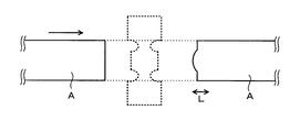
- FIG. 9 is a schematic explanatory diagram in the case of applying the double piece pass rolling in the rolling shaping with the fifth hole mold K5 (flat shaped hole mold) in the method for manufacturing the H-section steel according to the present embodiment. It is the schematic plan view seen from the upper part.
- FIG. 9 shows a material A to be rolled before rolling shaping in a certain pass (left side in the figure) and after rolling shaping in the pass (right side in the figure).
- the rolling shaping shown in FIG. 6 is performed from the start of rolling shaping until just before the end of rolling shaping, as in the edging rolling stage. For this reason, rolling shaping is performed with a roll gap necessary for the purpose.
- the rolling modeling for the predetermined section L from the end of rolling modeling in the pass to the end of rolling modeling is performed with the roll gap widened.
- the roll gap may be expanded stepwise so as to gradually reduce the amount of reduction immediately before the end of rolling shaping, or the roll gap may be greatly expanded so that the reduction amount is zero.
- the rolling shaping is performed on the material A to be rolled in a state where the amount of reduction is small (or no amount of reduction) for the predetermined section L compared to other sections.
- the flange part and the web part are not reduced so much. Therefore, even when the reduction ratio of the web portion is relatively large compared to the flange portion in the flat hole type rolling stage, the elongation of the web portion is elongated in the longitudinal direction of the material A to be rolled because the reduction rate itself is extremely small. Even if it exceeds the elongation of the flange portion, the so-called tongue-shaped defective portion (see FIG. 7B) is not formed remarkably as shown in FIG.
- rolling modeling is performed in a direction opposite to the direction shown in FIG. 9 in the next pass of the pass described in FIG. That is, the predetermined section L becomes a biting end in the next pass.
- the rolling modeling is applied to the predetermined section L as a biting end in this pass. That is, sufficient rolling modeling is performed for the predetermined section L as well.
- the reduction amount for the predetermined section L in the next path of the path described in FIG. 9 needs to be added at the same time as the reduction amount in the next path, It is important to sufficiently examine the amount of reduction for the predetermined section L.
- the double piece pass rolling is applied in the edging rolling stage (FIG. 8) and the case where the double piece pass rolling is applied in the flat hole rolling stage (FIG. 9), respectively.
- the double piece pass rolling is applied only to the edging rolling stage (that is, the rolling shaping corresponding to the first hole type K1 to the fourth hole type K4).
- it may be applied only to the flat hole rolling stage (that is, the rolling shaping corresponding to the fifth hole mold K5), and may be applied to both the edging rolling stage and the flat hole rolling stage. .
- the intermediate crop cutting step can be omitted or simplified, and the yield can be improved and the rolling efficiency can be improved.
- double-piece pass rolling may be applied in a predetermined arbitrary pass, or may be applied in all passes. From the viewpoint that it is desirable to suppress the growth of the cropped portion without forming the defective shape portion, it is desirable to apply double-piece pass rolling in all passes.
- the predetermined section L required to perform the rolling shaping with the roll gap widened can be arbitrarily set.
- the predetermined section L is preferably set.
- the predetermined section L When determining the predetermined section L, it is necessary to clarify the boundary between the unsteady part and the steady part in rolling of the material A to be rolled, and to include at least the unsteady part in the predetermined section L.
- the steady portion When the steady portion is included in the predetermined section L, the roll gap is widened in a partial range of the steady portion, and there is a possibility that a rolling reduction remains in the steady portion.
- the predetermined section L be in a range that includes the entire range of the unsteady portion and can be expanded to a part of the steady portion.
- each pass is performed by performing a laboratory experiment or an actual machine test. Each time the unsteady part length is measured, a suitable length is determined.
- the upper and lower ends (slab end surfaces) of the material A to be rolled are interrupted, and the respective parts divided into left and right by the interruption are bent left and right.
- the flange part 80 By forming the flange part 80 by performing the processing, the H-shaped rough shaped member 13 can be formed without substantially lowering the upper and lower end surfaces of the material to be rolled A (slab) in the vertical direction. That is, compared with the conventional rough rolling method in which the end face of the slab is always squeezed, the flange width can be widened to form the H-shaped rough shape 13, and as a result, a final product having a large flange width ( H-shaped steel) can be manufactured.
- an edging rolling stage that is, rolling modeling corresponding to the first hole mold K1 to the fourth hole mold K4
- the flat hole rolling stage that is, rolling modeling corresponding to the fifth hole mold K5
- the roll gap is widened at the time of rolling modeling with respect to the predetermined section L of the material A to be rolled (the tail end at the time of rolling modeling).
- the intermediate crop cutting process can be omitted or simplified, and the yield can be improved and the rolling efficiency can be improved. That is, most ideally, the rough rolling process, the intermediate rolling process, and the finish rolling process can all be performed without interposing the intermediate crop cutting process, and the crop cutting is performed in all processes (rough rolling process, intermediate rolling process, The removal of the crop portion generated in the longitudinal direction of the material to be rolled can be completed only by carrying out after the finish rolling step). In addition, if necessary, an intermediate crop cutting process is performed only on the web portion of the material to be rolled after the rough rolling process and before or during the intermediate rolling process (between rolling passes in the intermediate rolling process). Also good.
- the weight per unit length of the material A to be rolled is large and the product elongation during rolling is short.
- the proportion of the crop portion in the total length is large, and the growth of the crop portion tends to lead to a decrease in yield. Therefore, the technique for suppressing the growth of the crop portion according to the present embodiment is particularly useful in the manufacture of large H-section steel products.
- the number of hole molds for performing the rough rolling process is not limited to this, and the rolling shaping process shown in the first hole mold K1 to the fourth hole mold K4 is performed using more hole molds. May be. That is, the hole shape configuration shown in the above embodiment is an example, and the number of hole shapes engraved in the sizing mill 3 and the rough rolling mill 4 can be arbitrarily changed, and the rough rolling process is preferably performed. It is suitably changed to such an extent that it can be performed.
- the slab has been described as an example of the material for manufacturing the H-section steel, the present invention is naturally applicable to other materials having similar shapes. That is, for example, the present invention can also be applied to the case where an H-shaped steel is manufactured by shaping a beam blank material.
- Example 1 As Reference Example 1, edging rolling was performed using a conventional H-shaped steel manufacturing technique based on the wedge method, and the crop length (crop length) at that time was measured. On the other hand, as Reference Example 2, edging rolling was performed by the split method using the first hole mold K1 to the third hole mold K3 shown in FIGS. 2 to 4, and the crop portion length at that time was measured.
- the material slab cross section is 1800 mm ⁇ 300 mm
- the wedge angle in the edging rolling in the embodiment is 30 ° in the first hole mold K1 and the second hole mold K2, and in the third hole mold K3. The angle was 90 °.
- the edging amount was the amount of reduction at the protrusion tip position (wedge tip position) in each hole mold.
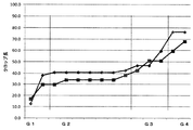
- FIG. 10 is a graph showing verification results of Reference Example 1 (the wedge method in the figure) and Reference Example 2 (the split method in the figure), and the edging amount (the amount of reduction by edging rolling) and the crop length in each case. It is a graph which shows the relationship.
- the description of G1 to G3 in FIG. 10 corresponds to the edging rolling in the first hole mold K1 to the third hole mold K3 according to the above embodiment.
- the plot of FIG. 10 takes the average value of the crop length at both ends in the longitudinal direction of the material to be rolled.
- the crop length grew almost in proportion to the edging amount. For example, when the edging amount was 600 mm, the crop length grew to about 250 mm.
- Example 2 As a comparative example, edging rolling was performed without applying double piece pass rolling by a split method using the first hole mold K1 to the fourth hole mold K4 shown in FIGS. 2 to 5, and both ends of the material to be rolled at that time The crop part length (crop length) was measured.
- FIG. 12 is a graph showing the measurement results of the comparative example, and two plots in the graph show the crop lengths at both ends in the longitudinal direction of the material to be rolled.
- the first hole type K1, the third hole type K3, the fourth hole type K4 Double piece pass rolling was performed in all passes of rolling shaping in G1, G3, and G4 in the drawing, and the lengths of the cropped portions (crop lengths) at both ends of the material to be rolled at that time were measured.
- FIG. 13 is a graph showing measurement results of Examples, and two plots in the graph indicate crop lengths at both ends in the longitudinal direction of the material to be rolled.
- the roll gap was expanded from about 400 mm at the end of the material to be rolled in each rolling pass, and the roll was opened at the final end.
- the material slab used in the comparative examples and examples is a slab having a cross section of 2300 mm ⁇ 300 mm and a length of 4000 mm.
- the rolling pass schedule in each hole type is as shown in Table 1 below.
- the “roll gap” in Table 1 indicates the interval (distance) between the tip portions of the wedges (projections) of the hole-type upper and lower rolls, and is synonymous with the “edging amount” in Experimental Example 1 above. .
- the amount of crop growth in each hole type is suppressed in the case of applying double-piece pass rolling (FIG. 13) compared to the case of non-application (FIG. 12).
- the amount of crop growth in G1, G3, and G4 is greatly suppressed.
- the final crop length is about 40 mm or less when double-piece pass rolling is applied, and about 90 mm or less when non-application is applied. became.
- the present invention can be applied to a manufacturing technique for manufacturing H-section steel using, for example, a slab having a rectangular cross section as a raw material.
Landscapes
- Engineering & Computer Science (AREA)
- Mechanical Engineering (AREA)
- Metal Rolling (AREA)
Abstract
Description
本願は、2016年4月28日に日本国に出願された特願2016-090165号に基づき、優先権を主張し、その内容をここに援用する。
特に、大型のH形鋼製品の製造では、被圧延材の単位長さあたりの重量が大きく、圧延時の製品伸び長さが短いために、全長に占めるクロップ部の割合が大きく、当該クロップ部の成長は歩留まりの低下につながり易い。従って、特に大型のH形鋼製品の製造において、クロップ部の成長をできるだけ低減させることが求められているのが実情である。
また、被圧延材Aの上下端部(スラブ端面)に対向する孔型上面30a、30b及び孔型底面31a、31bと、突起部35、36の傾斜面とのなす角度θfは、図3に示す4箇所ともに約90°(略直角)に構成されている。
また、被圧延材Aの上下端部(スラブ端面)に対向する孔型上面40a、40b及び孔型底面41a、41bと、突起部45、46の傾斜面とのなす角度θfは、図4に示す4箇所ともに約90°(略直角)に構成されている。
また、被圧延材Aの上下端部(スラブ端面)に対向する孔型上面50a、50b及び孔型底面51a、51bと、突起部55、56の傾斜面とのなす角度θfは、上記第3孔型K3と同様に、図5に示す4箇所ともに約90°(略直角)に構成されている。
このような造形技術にあっては、第1孔型K1~第4孔型K4での造形において、被圧延材Aの上下端部(スラブ端面)を積極的に圧下することなく圧延造形が進められ、被圧延材A(特に、フランジ部80)の長手方向への伸びは極めて小さいものとなる。
図7は、従来のH形鋼圧延技術に関する概略説明図であり、(a)は従来のエッジング圧延を側面から見た概略側面図であり、(b)は従来の平孔型圧延を上方から見た概略平面図である。なお、図7における左側が圧延上流側を示している。
その後、図7(b)に示すように、従来のH形鋼製造技術では、平孔型圧延段階でフランジ部に比べウェブ部の圧下率が相対的に大きいため、被圧延材Aの長手方向においてウェブ部の伸びがフランジ部の伸びを上回り、いわゆるタングと呼ばれるクロップ形状部92が形成されてしまう(図7(b)中の破線部参照)。
このようなフィッシュテールあるいはタングと呼ばれるクロップ形状部90、92は、圧延の噛み込み端と圧延蹴出し端の両方で形成・成長するが、特に、圧延蹴出し端における成長が著しいことが知られている。
なお、このように形成されるクロップ形状部90の長手方向長さをL1とし、クロップ形状部92の長手方向長さをL2とする。
上述したように、従来の製造技術では、フィッシュテールあるいはタングと呼ばれるクロップ形状部90、92は、圧延の噛み込み端と圧延蹴出し端の両方で形成・成長し、特に、圧延蹴出し端における成長が顕著であるが、上記ダブル片パス圧延を適用して所定の区間での圧下量を低下あるいは0とすることで、クロップ形状部90、92の成長を抑制させることができる。
ここで、図8には、第1孔型K1を例示して説明したが、同様の作用効果は、エッジング圧延段階に用いられる各孔型にいえるものであり、ダブル片パス圧延はエッジング圧延段階に用いる1又は複数の孔型に適用することも可能である。
なお、第1孔型K1において形成された割り込みを更に深くするような造形を行う第2孔型K2に関しては、形状不良部(クロップ部)の成長が小さいことから、必ずしもダブル片パス圧延を適用しなくても良い。
また、圧延ロール隙が拡げられて圧延造形される当該所定区間では、被圧延材の端面と孔型周面とが接触していなくても良い。但し、被圧延材の端面と孔型周面とが接触するパスが1パスである場合、被圧延材の長手方向後端部に未圧下部が残存する恐れがあるため、更に接触パスを1パス増やして形状を整えることが必要となる場合がある。そのような場合などには、第2孔型K2での全パスにおいて、ダブル片パス圧延を行っても良い。
また、各圧延造形段階においてリバース圧延を採用する場合に、ダブル片パス圧延を所定の任意のパスで適用しても良く、全てのパスで適用しても良い。形状不良部を形成させずに、クロップ部の成長を抑制させることが望ましいといった観点からは、全てのパスでダブル片パス圧延を適用することが望ましい。
以下では、先ず、特許文献1等に例示される、従来のH形鋼製造技術に係る製造方法(以下、ウェッジ法とも呼称する)と、本願発明技術に係る製造方法(以下、スプリット法とも呼称する)とを比較する実験を行った結果を実験例1として示す。そして、スプリット法において、上記実施の形態で説明した、いわゆる「ダブル片パス圧延」の適用有無を比較する実験を行った結果を実験例2として示す。
参考例1として、従来法であるウェッジ法によるH形鋼製造技術を用いてエッジング圧延を行い、その時のクロップ部長さ(クロップ長)を測定した。一方、参考例2として、図2~図4に示した第1孔型K1~第3孔型K3を用いてスプリット法によるエッジング圧延を行い、その時のクロップ部長さを測定した。なお、本検証の条件として、素材スラブ断面を1800mm×300mmとし、実施例におけるエッジング圧延でのウェッジ角度は、第1孔型K1及び第2孔型K2で30°とし、第3孔型K3で90°とした。また、エッジング量は各孔型での突起部先端位置(ウェッジ先端位置)での圧下量とした。
図10に示すように、参考例1では、クロップ長がエッジング量にほぼ比例して成長しており、例えばエッジング量が600mmの時、クロップ長は約250mmまで成長した。
一方、参考例2では、クロップ長に多少の成長は見られるものの、特に第2孔型K2(図中のG2)でのクロップ部の成長は見られず、クロップ長の成長が比較例と比べて抑制されていることが分かる。例えばエッジング量が900mmの時、クロップ長は約80mmに留まっている。
比較例として、図2~図5に示した第1孔型K1~第4孔型K4を用いたスプリット法により、ダブル片パス圧延を適用せずにエッジング圧延を行い、その時の被圧延材両端のクロップ部長さ(クロップ長)を測定した。図12は、比較例の測定結果を示すグラフであり、グラフ中の2つのプロットは、被圧延材の長手方向両端のクロップ長を示すものである。
実施例においてダブル片パス圧延を行う場合には、各圧延パスにおいて被圧延材の終端部の約400mmからロール隙を拡げ、最終端部ではロール開放を行った。

2…加熱炉
3…サイジングミル
4…粗圧延機
5…中間ユニバーサル圧延機
8…仕上ユニバーサル圧延機
9…エッジャー圧延機
11…スラブ
13…H形粗形材
14…中間材
16…H形鋼製品
20…上孔型ロール(第1孔型)
21…下孔型ロール(第1孔型)
25、26…突起部(第1孔型)
28、29…割り込み(第1孔型)
30…上孔型ロール(第2孔型)
31…下孔型ロール(第2孔型)
35、36…突起部(第2孔型)
38、39…割り込み(第2孔型)
40…上孔型ロール(第3孔型)
41…下孔型ロール(第3孔型)
45、46…突起部(第3孔型)
48、49…割り込み(第3孔型)
50…上孔型ロール(第4孔型)
51…下孔型ロール(第4孔型)
55、56…突起部(第4孔型)
58、59…割り込み(第4孔型)
80…フランジ部
82…ウェブ部
85…上孔型ロール(第5孔型)
86…下孔型ロール(第5孔型)
90、92…クロップ形状部
K1…第1孔型
K2…第2孔型
K3…第3孔型
K4…第4孔型
K5…第5孔型(平造形孔型)
T…製造ライン
A…被圧延材
Claims (11)
- 粗圧延工程、中間圧延工程、仕上圧延工程を備えたH形鋼の製造方法であって、
前記粗圧延工程を行う圧延機には、被圧延材を圧延造形する5以上の複数の孔型が刻設され、
当該複数の孔型では被圧延材の1又は複数パス造形が行われ、
前記複数の孔型のうち第1孔型及び第2孔型には、被圧延材の幅方向に対し鉛直に割り込みを入れて被圧延材端部に分割部位を形成させる突起部が形成され、
前記複数の孔型のうち最終孔型を除く第3孔型以降には、前記割り込みに当接し、形成された分割部位を順次折り曲げる突起部が形成され、
前記複数の孔型のうち最終孔型は平造形孔型であり、
前記複数の孔型のうち最終孔型を除く第2孔型以降では少なくとも1パス以上の造形において被圧延材の端面と孔型周面とが接触した状態で圧下が行われ、
前記複数の孔型における圧延造形の少なくとも1パス以上で、被圧延材の圧延長手方向後端部の所定区間に対する圧延ロール隙を当該所定区間以外に対する圧延ロール隙に比べ拡げて圧延造形を行うことを特徴とする、H形鋼の製造方法。 - 前記第1孔型及び第2孔型に形成された突起部の先端部角度は25°以上40°以下であることを特徴とする、請求項1に記載のH形鋼の製造方法。
- 前記複数の孔型のうち第1孔型での圧延造形の全パスにおいて、被圧延材の圧延長手方向後端部の所定区間に対する圧延ロール隙を当該所定区間以外に対する圧延ロール隙に比べ拡げて圧延造形を行うことを特徴とする、請求項1又は2に記載のH形鋼の製造方法。
- 前記複数の孔型のうち少なくとも第3孔型及び第4孔型での圧延造形の全パスにおいて、被圧延材の圧延長手方向後端部の所定区間に対する圧延ロール隙を当該所定区間以外に対する圧延ロール隙に比べ拡げて圧延造形を行うことを特徴とする、請求項1~3のいずれか一項に記載のH形鋼の製造方法。
- 前記複数の孔型のうち第2孔型での圧延造形において、被圧延材の端面と当該第2孔型の孔型周面とが接触した状態で圧下が行われるパスでは、被圧延材の圧延長手方向後端部の所定区間に対する圧延ロール隙を当該所定区間以外に対する圧延ロール隙に比べ拡げて圧延造形を行うことを特徴とする、請求項1~4のいずれか一項に記載のH形鋼の製造方法。
- 前記複数の孔型のうち最終孔型での圧延造形の全パスにおいて、被圧延材の圧延長手方向後端部の所定区間に対する圧延ロール隙を当該所定区間以外に対する圧延ロール隙に比べ拡げて圧延造形を行うことを特徴とする、請求項1~5のいずれか一項に記載のH形鋼の製造方法。
- 前記複数の孔型のうち第1孔型及び最終孔型を除く全ての孔型での圧延造形の全パスにおいて、被圧延材の圧延長手方向後端部の所定区間に対する圧延ロール隙を当該所定区間以外に対する圧延ロール隙に比べ拡げて圧延造形を行うことを特徴とする、請求項1~6に記載のH形鋼の製造方法。
- 前記粗圧延工程後、且つ、前記中間圧延工程の前段階において、被圧延材のウェブ部のみに対して中間クロップ切断工程を行うことを特徴とする、請求項1~7のいずれか一項に記載のH形鋼の製造方法。
- 前記粗圧延工程、中間圧延工程、仕上圧延工程の全てを完了した後に、被圧延材の長手方向端部に形成されたクロップ形状部を初めて除去することを特徴とする、請求項1~7のいずれか一項に記載のH形鋼の製造方法。
- 前記粗圧延工程を行う圧延機には、当該圧延機の孔型ロールのロール隙を変更する圧下機構が設けられていることを特徴とする、請求項1~9のいずれか一項に記載のH形鋼の製造方法。
- 請求項1~10のいずれか一項に記載のH形鋼の製造方法によって製造されるH形鋼製品であって、
ウェブ高さ1000mm以上、又は、フランジ幅が400mm以上であることを特徴とする、H形鋼製品。
Priority Applications (4)
| Application Number | Priority Date | Filing Date | Title |
|---|---|---|---|
| JP2018514581A JP6614339B2 (ja) | 2016-04-28 | 2017-04-24 | H形鋼の製造方法 |
| CN201780024850.7A CN109070157A (zh) | 2016-04-28 | 2017-04-24 | H型钢的制造方法 |
| EP17789461.5A EP3412370A4 (en) | 2016-04-28 | 2017-04-24 | METHOD FOR PRODUCING H-SHAPED STEEL |
| US16/082,334 US20190022719A1 (en) | 2016-04-28 | 2017-04-24 | Method for producing h-shaped steel |
Applications Claiming Priority (2)
| Application Number | Priority Date | Filing Date | Title |
|---|---|---|---|
| JP2016-090165 | 2016-04-28 | ||
| JP2016090165 | 2016-04-28 |
Publications (1)
| Publication Number | Publication Date |
|---|---|
| WO2017188179A1 true WO2017188179A1 (ja) | 2017-11-02 |
Family
ID=60160496
Family Applications (1)
| Application Number | Title | Priority Date | Filing Date |
|---|---|---|---|
| PCT/JP2017/016180 Ceased WO2017188179A1 (ja) | 2016-04-28 | 2017-04-24 | H形鋼の製造方法 |
Country Status (5)
| Country | Link |
|---|---|
| US (1) | US20190022719A1 (ja) |
| EP (1) | EP3412370A4 (ja) |
| JP (1) | JP6614339B2 (ja) |
| CN (1) | CN109070157A (ja) |
| WO (1) | WO2017188179A1 (ja) |
Families Citing this family (1)
| Publication number | Priority date | Publication date | Assignee | Title |
|---|---|---|---|---|
| CN115382903A (zh) * | 2022-08-29 | 2022-11-25 | 中重科技(天津)股份有限公司 | 一种压力机劈轧板坯生产h型钢的方法 |
Citations (4)
| Publication number | Priority date | Publication date | Assignee | Title |
|---|---|---|---|---|
| JPS57146405A (en) * | 1981-03-05 | 1982-09-09 | Kawasaki Steel Corp | Broadside rolling method and rolling roll for large sized blank material for rough shape |
| JPS589701A (ja) * | 1981-07-10 | 1983-01-20 | Sumitomo Metal Ind Ltd | 粗形鋼片の製造方法 |
| JPH07265901A (ja) * | 1994-03-29 | 1995-10-17 | Nippon Steel Corp | H形鋼用粗形鋼片の粗圧延法 |
| JP2002045902A (ja) * | 2000-08-02 | 2002-02-12 | Sumitomo Metal Ind Ltd | 大型h形鋼の圧延方法 |
Family Cites Families (14)
| Publication number | Priority date | Publication date | Assignee | Title |
|---|---|---|---|---|
| US2890735A (en) * | 1957-07-17 | 1959-06-16 | Inland Steel Co | Tongue bender |
| US4106318A (en) * | 1974-04-10 | 1978-08-15 | Nippon Steel Corporation | Method and apparatus for rolling metallic material |
| US4202192A (en) * | 1978-06-21 | 1980-05-13 | Nippon Steel Corporation | Apparatus for controlling the position of roll in the direction of the roll axis |
| JPS58188501A (ja) * | 1982-04-30 | 1983-11-04 | Sumitomo Metal Ind Ltd | H形鋼用粗形鋼片の製造方法 |
| JPS58215204A (ja) * | 1982-06-09 | 1983-12-14 | Kawasaki Steel Corp | H形鋼圧延方法 |
| JPS6182903A (ja) * | 1984-09-28 | 1986-04-26 | Sumitomo Metal Ind Ltd | フランジ内面に突起を有するh形鋼の圧延法 |
| JPS6192701A (ja) * | 1984-10-11 | 1986-05-10 | Nippon Kokan Kk <Nkk> | H形粗形鋼片の圧延方法 |
| JPS61126930A (ja) * | 1984-11-26 | 1986-06-14 | Kawasaki Steel Corp | H形鋼フランジ先端整形方法 |
| US5167166A (en) * | 1991-10-11 | 1992-12-01 | Teleflex Incorporated | Rack and roller core element adjust |
| DE4134599C1 (ja) * | 1991-10-18 | 1993-02-25 | Thyssen Stahl Ag, 4100 Duisburg, De | |
| DE4207297A1 (de) * | 1992-03-07 | 1993-09-09 | Schloemann Siemag Ag | Verfahren und vorrichtung zum richten von h-foermigen traegerprofilen |
| JP3678003B2 (ja) * | 1998-06-03 | 2005-08-03 | Jfeスチール株式会社 | 粗形鋼片の圧延方法 |
| IT1315029B1 (it) * | 2000-08-28 | 2003-01-27 | Danieli Off Mecc | Metodo e linea per la laminazione di rotaie o altre sezioni |
| CN103203357A (zh) * | 2013-03-05 | 2013-07-17 | 安阳市常兴轧钢有限责任公司 | T型钢在横列式三辊轧机上的轧制工艺 |
-
2017
- 2017-04-24 EP EP17789461.5A patent/EP3412370A4/en not_active Withdrawn
- 2017-04-24 CN CN201780024850.7A patent/CN109070157A/zh active Pending
- 2017-04-24 JP JP2018514581A patent/JP6614339B2/ja active Active
- 2017-04-24 WO PCT/JP2017/016180 patent/WO2017188179A1/ja not_active Ceased
- 2017-04-24 US US16/082,334 patent/US20190022719A1/en not_active Abandoned
Patent Citations (4)
| Publication number | Priority date | Publication date | Assignee | Title |
|---|---|---|---|---|
| JPS57146405A (en) * | 1981-03-05 | 1982-09-09 | Kawasaki Steel Corp | Broadside rolling method and rolling roll for large sized blank material for rough shape |
| JPS589701A (ja) * | 1981-07-10 | 1983-01-20 | Sumitomo Metal Ind Ltd | 粗形鋼片の製造方法 |
| JPH07265901A (ja) * | 1994-03-29 | 1995-10-17 | Nippon Steel Corp | H形鋼用粗形鋼片の粗圧延法 |
| JP2002045902A (ja) * | 2000-08-02 | 2002-02-12 | Sumitomo Metal Ind Ltd | 大型h形鋼の圧延方法 |
Non-Patent Citations (2)
| Title |
|---|
| ANONYMOUS: "Passage, KENCHIKU- YO SHIZAI HANDBOOK", KENCHIKU- YO SHIZAI HANDBOOK, August 2014 (2014-08-01), pages 152 - 153, XP009516411 * |
| See also references of EP3412370A4 * |
Also Published As
| Publication number | Publication date |
|---|---|
| JP6614339B2 (ja) | 2019-12-04 |
| CN109070157A (zh) | 2018-12-21 |
| US20190022719A1 (en) | 2019-01-24 |
| EP3412370A1 (en) | 2018-12-12 |
| EP3412370A4 (en) | 2019-10-23 |
| JPWO2017188179A1 (ja) | 2018-11-29 |
Similar Documents
| Publication | Publication Date | Title |
|---|---|---|
| KR20190030755A (ko) | H형강의 제조 방법 | |
| JP2019111584A (ja) | 圧延h形鋼 | |
| JP6614339B2 (ja) | H形鋼の製造方法 | |
| JP6447286B2 (ja) | H形鋼の製造方法及びh形鋼製品 | |
| JP6668963B2 (ja) | H形鋼の製造方法 | |
| JP6614396B1 (ja) | H形鋼の製造方法 | |
| JP6593457B2 (ja) | H形鋼の製造方法及び圧延装置 | |
| JP2017121654A (ja) | H形鋼の製造方法 | |
| JP6686809B2 (ja) | H形鋼の製造方法 | |
| JP6565691B2 (ja) | H形鋼の製造方法及びh形鋼製品 | |
| JP6593456B2 (ja) | H形鋼の製造方法及びh形鋼製品 | |
| JP6627641B2 (ja) | H形鋼の製造方法 | |
| JP6501047B1 (ja) | H形鋼の製造方法 | |
| JP6597321B2 (ja) | H形鋼の製造方法及びh形鋼製品 | |
| JP6515365B1 (ja) | H形鋼の製造方法 | |
| JP6790973B2 (ja) | H形鋼の製造方法 | |
| JP6575725B1 (ja) | H形鋼の製造方法 | |
| JP6569535B2 (ja) | H形鋼の製造方法及びh形鋼製品 | |
| JP6531653B2 (ja) | H形鋼の製造方法 | |
| JP6855885B2 (ja) | H形鋼の製造方法及びh形鋼製品 | |
| JP6447285B2 (ja) | H形鋼の製造方法 | |
| WO2016148031A1 (ja) | H形鋼の製造方法 | |
| JP2019206010A (ja) | H形鋼の製造方法 |
Legal Events
| Date | Code | Title | Description |
|---|---|---|---|
| WWE | Wipo information: entry into national phase |
Ref document number: 2018514581 Country of ref document: JP |
|
| WWE | Wipo information: entry into national phase |
Ref document number: 2017789461 Country of ref document: EP |
|
| ENP | Entry into the national phase |
Ref document number: 2017789461 Country of ref document: EP Effective date: 20180907 |
|
| NENP | Non-entry into the national phase |
Ref country code: DE |
|
| 121 | Ep: the epo has been informed by wipo that ep was designated in this application |
Ref document number: 17789461 Country of ref document: EP Kind code of ref document: A1 |