WO2017188318A1 - Dispositif d'éclairage naturel et système d'éclairage naturel - Google Patents
Dispositif d'éclairage naturel et système d'éclairage naturel Download PDFInfo
- Publication number
- WO2017188318A1 WO2017188318A1 PCT/JP2017/016558 JP2017016558W WO2017188318A1 WO 2017188318 A1 WO2017188318 A1 WO 2017188318A1 JP 2017016558 W JP2017016558 W JP 2017016558W WO 2017188318 A1 WO2017188318 A1 WO 2017188318A1
- Authority
- WO
- WIPO (PCT)
- Prior art keywords
- slat
- daylighting
- light
- angle
- incident
- Prior art date
- Legal status (The legal status is an assumption and is not a legal conclusion. Google has not performed a legal analysis and makes no representation as to the accuracy of the status listed.)
- Ceased
Links
Images


Classifications
-
- E—FIXED CONSTRUCTIONS
- E06—DOORS, WINDOWS, SHUTTERS, OR ROLLER BLINDS IN GENERAL; LADDERS
- E06B—FIXED OR MOVABLE CLOSURES FOR OPENINGS IN BUILDINGS, VEHICLES, FENCES OR LIKE ENCLOSURES IN GENERAL, e.g. DOORS, WINDOWS, BLINDS, GATES
- E06B9/00—Screening or protective devices for wall or similar openings, with or without operating or securing mechanisms; Closures of similar construction
- E06B9/24—Screens or other constructions affording protection against light, especially against sunshine; Similar screens for privacy or appearance; Slat blinds
- E06B9/26—Lamellar or like blinds, e.g. venetian blinds
- E06B9/38—Other details
- E06B9/386—Details of lamellae
-
- E—FIXED CONSTRUCTIONS
- E06—DOORS, WINDOWS, SHUTTERS, OR ROLLER BLINDS IN GENERAL; LADDERS
- E06B—FIXED OR MOVABLE CLOSURES FOR OPENINGS IN BUILDINGS, VEHICLES, FENCES OR LIKE ENCLOSURES IN GENERAL, e.g. DOORS, WINDOWS, BLINDS, GATES
- E06B9/00—Screening or protective devices for wall or similar openings, with or without operating or securing mechanisms; Closures of similar construction
- E06B9/24—Screens or other constructions affording protection against light, especially against sunshine; Similar screens for privacy or appearance; Slat blinds
- E06B9/26—Lamellar or like blinds, e.g. venetian blinds
- E06B9/264—Combinations of lamellar blinds with roller shutters, screen windows, windows, or double panes; Lamellar blinds with special devices
-
- E—FIXED CONSTRUCTIONS
- E06—DOORS, WINDOWS, SHUTTERS, OR ROLLER BLINDS IN GENERAL; LADDERS
- E06B—FIXED OR MOVABLE CLOSURES FOR OPENINGS IN BUILDINGS, VEHICLES, FENCES OR LIKE ENCLOSURES IN GENERAL, e.g. DOORS, WINDOWS, BLINDS, GATES
- E06B9/00—Screening or protective devices for wall or similar openings, with or without operating or securing mechanisms; Closures of similar construction
- E06B9/24—Screens or other constructions affording protection against light, especially against sunshine; Similar screens for privacy or appearance; Slat blinds
- E06B9/26—Lamellar or like blinds, e.g. venetian blinds
- E06B9/28—Lamellar or like blinds, e.g. venetian blinds with horizontal lamellae, e.g. non-liftable
- E06B9/30—Lamellar or like blinds, e.g. venetian blinds with horizontal lamellae, e.g. non-liftable liftable
- E06B9/303—Lamellar or like blinds, e.g. venetian blinds with horizontal lamellae, e.g. non-liftable liftable with ladder-tape
-
- E—FIXED CONSTRUCTIONS
- E06—DOORS, WINDOWS, SHUTTERS, OR ROLLER BLINDS IN GENERAL; LADDERS
- E06B—FIXED OR MOVABLE CLOSURES FOR OPENINGS IN BUILDINGS, VEHICLES, FENCES OR LIKE ENCLOSURES IN GENERAL, e.g. DOORS, WINDOWS, BLINDS, GATES
- E06B9/00—Screening or protective devices for wall or similar openings, with or without operating or securing mechanisms; Closures of similar construction
- E06B9/24—Screens or other constructions affording protection against light, especially against sunshine; Similar screens for privacy or appearance; Slat blinds
- E06B9/26—Lamellar or like blinds, e.g. venetian blinds
- E06B9/28—Lamellar or like blinds, e.g. venetian blinds with horizontal lamellae, e.g. non-liftable
- E06B9/30—Lamellar or like blinds, e.g. venetian blinds with horizontal lamellae, e.g. non-liftable liftable
- E06B9/32—Operating, guiding, or securing devices therefor
- E06B9/322—Details of operating devices, e.g. pulleys, brakes, spring drums, drives
-
- F—MECHANICAL ENGINEERING; LIGHTING; HEATING; WEAPONS; BLASTING
- F21—LIGHTING
- F21S—NON-PORTABLE LIGHTING DEVICES; SYSTEMS THEREOF; VEHICLE LIGHTING DEVICES SPECIALLY ADAPTED FOR VEHICLE EXTERIORS
- F21S11/00—Non-electric lighting devices or systems using daylight
-
- F—MECHANICAL ENGINEERING; LIGHTING; HEATING; WEAPONS; BLASTING
- F21—LIGHTING
- F21S—NON-PORTABLE LIGHTING DEVICES; SYSTEMS THEREOF; VEHICLE LIGHTING DEVICES SPECIALLY ADAPTED FOR VEHICLE EXTERIORS
- F21S11/00—Non-electric lighting devices or systems using daylight
- F21S11/007—Non-electric lighting devices or systems using daylight characterised by the means for transmitting light into the interior of a building
-
- F—MECHANICAL ENGINEERING; LIGHTING; HEATING; WEAPONS; BLASTING
- F21—LIGHTING
- F21V—FUNCTIONAL FEATURES OR DETAILS OF LIGHTING DEVICES OR SYSTEMS THEREOF; STRUCTURAL COMBINATIONS OF LIGHTING DEVICES WITH OTHER ARTICLES, NOT OTHERWISE PROVIDED FOR
- F21V14/00—Controlling the distribution of the light emitted by adjustment of elements
- F21V14/06—Controlling the distribution of the light emitted by adjustment of elements by movement of refractors
-
- F—MECHANICAL ENGINEERING; LIGHTING; HEATING; WEAPONS; BLASTING
- F21—LIGHTING
- F21V—FUNCTIONAL FEATURES OR DETAILS OF LIGHTING DEVICES OR SYSTEMS THEREOF; STRUCTURAL COMBINATIONS OF LIGHTING DEVICES WITH OTHER ARTICLES, NOT OTHERWISE PROVIDED FOR
- F21V23/00—Arrangement of electric circuit elements in or on lighting devices
- F21V23/04—Arrangement of electric circuit elements in or on lighting devices the elements being switches
- F21V23/0442—Arrangement of electric circuit elements in or on lighting devices the elements being switches activated by means of a sensor, e.g. motion or photodetectors
- F21V23/0464—Arrangement of electric circuit elements in or on lighting devices the elements being switches activated by means of a sensor, e.g. motion or photodetectors the sensor sensing the level of ambient illumination, e.g. dawn or dusk sensors
-
- F—MECHANICAL ENGINEERING; LIGHTING; HEATING; WEAPONS; BLASTING
- F21—LIGHTING
- F21V—FUNCTIONAL FEATURES OR DETAILS OF LIGHTING DEVICES OR SYSTEMS THEREOF; STRUCTURAL COMBINATIONS OF LIGHTING DEVICES WITH OTHER ARTICLES, NOT OTHERWISE PROVIDED FOR
- F21V5/00—Refractors for light sources
- F21V5/02—Refractors for light sources of prismatic shape
-
- E—FIXED CONSTRUCTIONS
- E06—DOORS, WINDOWS, SHUTTERS, OR ROLLER BLINDS IN GENERAL; LADDERS
- E06B—FIXED OR MOVABLE CLOSURES FOR OPENINGS IN BUILDINGS, VEHICLES, FENCES OR LIKE ENCLOSURES IN GENERAL, e.g. DOORS, WINDOWS, BLINDS, GATES
- E06B9/00—Screening or protective devices for wall or similar openings, with or without operating or securing mechanisms; Closures of similar construction
- E06B9/24—Screens or other constructions affording protection against light, especially against sunshine; Similar screens for privacy or appearance; Slat blinds
- E06B2009/2417—Light path control; means to control reflection
-
- E—FIXED CONSTRUCTIONS
- E06—DOORS, WINDOWS, SHUTTERS, OR ROLLER BLINDS IN GENERAL; LADDERS
- E06B—FIXED OR MOVABLE CLOSURES FOR OPENINGS IN BUILDINGS, VEHICLES, FENCES OR LIKE ENCLOSURES IN GENERAL, e.g. DOORS, WINDOWS, BLINDS, GATES
- E06B9/00—Screening or protective devices for wall or similar openings, with or without operating or securing mechanisms; Closures of similar construction
- E06B9/24—Screens or other constructions affording protection against light, especially against sunshine; Similar screens for privacy or appearance; Slat blinds
- E06B9/26—Lamellar or like blinds, e.g. venetian blinds
- E06B9/264—Combinations of lamellar blinds with roller shutters, screen windows, windows, or double panes; Lamellar blinds with special devices
- E06B2009/2643—Screens between double windows
Definitions
- One embodiment of the present invention relates to a lighting device and a lighting system.
- This application claims priority based on Japanese Patent Application No. 2016-089662 filed in Japan on April 27, 2016, the contents of which are incorporated herein by reference.
- Patent Document 1 discloses a daylighting apparatus for taking sunlight into a room through a building window or the like.
- the daylighting device described in Patent Literature 1 includes a plurality of daylighting sheets arranged side by side and a rotation mechanism that rotates the daylighting sheet.
- Patent Document 1 describes that according to this daylighting apparatus, it is possible to appropriately adjust the deflection in order to avoid dazzling light entering the room according to the elevation angle of the sun.
- Patent Document 2 discloses an electric blind provided with a slat angle control device that controls the angle of a slat according to time and weather.
- the problems with this structure are that the light incident surface is vertical (parallel to the substrate), the critical angle of total reflection is smaller than that of air because it is filled with a low refractive index material, and the upper part of the slat is seasonal. Therefore, a special blind structure is required because it is necessary to be able to rotate both indoors and outdoors. Thus, it is difficult to realize a daylighting device that satisfies both the suppression of glare and the efficient daylighting of sunlight.
- One aspect of the present invention has been made in order to solve the above-described problems, and an object thereof is to provide a daylighting apparatus and a daylighting system that can achieve both glare suppression and efficient daylighting.
- a daylighting apparatus includes a first slat having light permeability that bends an optical path of light incident from the outside and emits the light toward a predetermined direction in the room.
- a first drive mechanism that drives the first slat; and a control unit that controls the first drive mechanism so as to change an inclination angle of the first slat according to the position of the sun. .
- the first slat may include a plurality of prism structures that change the direction of light in a vertical plane.
- the prism structure mainly functions as a reflection surface of the light, a first surface that forms an angle ⁇ with a reference surface of the first slat, and the incidence of the light. It may function as a surface or an emission surface, and may have at least a second surface that forms an angle ⁇ with the reference surface.
- the daylighting device includes a correlation between a date and time and a tilt angle of the first slat, or a correlation between an incident angle of light on the first slat and a tilt angle of the first slat.
- a storage unit storing a relationship may be provided, and the control unit may control an inclination angle of the first slat based on the correlation stored in the storage unit.
- the daylighting device has an incident height of direct light with respect to a horizontal plane as ⁇ in, an incident direction of the direct light with respect to the horizontal plane as ⁇ in, an inclination angle of the first slat as ⁇ ,
- the controller tilts the upper portion of the first slat toward the indoor side when the offset angle of the light emitted from the first slat from the horizontal plane is ⁇ .
- ⁇ is a negative value
- ⁇ is a positive value
- ⁇ out f ( ⁇ in, ⁇ in, ⁇ )
- the minimum ⁇ that satisfies ⁇ ⁇ may be derived.
- control unit may determine the offset angle ⁇ based on a lower end position of the first slat and a depth of a room in which the lighting device is installed.
- the correlation may be a correlation with respect to the direct light reflected once within the prism structure.
- the daylighting device includes an input unit that inputs the posture of the first slat from the outside, and the control unit is configured to perform the operation based on the signal input from the input unit and the correlation.
- the tilt angle of the first slat may be controlled.
- the prism structure includes the first surface and the second surface arranged on the outdoor side, and 0 ° ⁇ ⁇ 90 ° and 0 ° ⁇ ⁇ ⁇ 90 °. And a combination of the angle ⁇ and the angle ⁇ satisfying ⁇ ⁇ ⁇ may be at least partially included.
- the angle ⁇ and the angle ⁇ may satisfy 64 ° ⁇ ⁇ 90 ° and 42 ° ⁇ ⁇ ⁇ 90 °.
- the prism structure includes the first surface and the second surface arranged on the indoor side, and 0 ° ⁇ ⁇ 90 ° and 0 ° ⁇ ⁇ ⁇ 90 °. And a combination of the angle ⁇ and the angle ⁇ satisfying ⁇ ⁇ ⁇ may be at least partially included.
- the angle ⁇ and the angle ⁇ may satisfy 51 ° ⁇ ⁇ 83 ° and 33 ° ⁇ ⁇ ⁇ 90 °.
- the first slat may be bent along a fold line parallel to the longitudinal direction of the first slat.
- the first region having the polygonal line as a boundary may include the plurality of prism structures, and the second region may have light absorptivity.
- the second surface may have a curved cross-sectional shape perpendicular to the longitudinal direction of the prism structure.
- the daylighting device includes a first slat having a light transmittance that bends an optical path of light incident from the outside and emits the light toward a predetermined direction in the room, and a lower portion of the first slat.
- a second slat that is arranged and shields or diffuses and transmits light incident from the outside, a drive mechanism that drives at least one of the first slat or the second slat, and the position of the sun
- a controller that controls the drive mechanism so as to change the tilt angle of the at least one slat, and the first slat includes a plurality of prism structures that change the direction of light in a vertical plane.
- the prism structure functions mainly as a reflection surface of the light, and functions as a first surface that forms an angle ⁇ with a reference surface of the first slat, and an incident surface or an emission surface of the light. And has a second surface which forms the reference plane and the angle beta, at least.
- the second slat may be capable of changing an inclination angle by being driven in conjunction with or independently of the first slat.
- the daylighting device includes a direct light detection unit that detects direct light around the daylighting device, and the control unit detects the first direct light detected by the direct light detection unit.
- the inclination angle of the slats may be controlled.
- a daylighting system includes the daylighting apparatus according to one aspect of the present invention, and a multi-layer glass in which a pair of glass plates are arranged to face each other with a gap therebetween, and the daylighting apparatus Is provided between the pair of glass plates.
- a daylighting system controls the daylighting device according to one aspect of the present invention, an indoor lighting device, a detection unit that detects indoor brightness, the indoor lighting device, and the detection unit.
- a control unit, and the control unit may control the indoor lighting device based on the illuminance detected by the detection unit.
- FIG. 3B is a cross-sectional view taken along line A-A ′ of FIG. 3A. It is a perspective view of a lighting slat. It is sectional drawing of a lighting part. It is a 1st figure for demonstrating the effect
- each member is appropriately changed to make each member a recognizable size.
- the positional relationship (upper, left, right, front and rear) of the daylighting device is based on the positional relationship (upper, lower, left and right, front and rear) when the daylighting device is used. In this case, the positional relationship of the daylighting device is assumed to coincide with the positional relationship with respect to the paper surface.
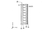
- FIG. 1 is a perspective view showing a daylighting apparatus according to the first embodiment.
- the vertical direction vertical direction
- the horizontal direction is the x direction
- the near side the back direction is the z direction.
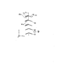
- FIG. 2 is a side view of the daylighting apparatus according to the first embodiment.
- the daylighting apparatus 1 includes a daylighting unit 3 including a plurality of daylighting slats 2, a support mechanism 4, a drive mechanism 5, and a control unit 6.
- the plurality of daylighting slats 2 are suspended in the vertical direction (y direction) at intervals.
- Each of the daylighting slats 2 is arranged so that the longitudinal direction of the daylighting slats 2 is directed in the horizontal direction (x direction).
- the support mechanism 4 supports the plurality of daylighting slats 2 so as to be movable up and down and rotatable.
- the daylighting slat 2 is configured so that the upper side of the daylighting slat 2 can be rotated in a direction to fall to the indoor side.
- the daylighting slat 2 of the present embodiment corresponds to the first slat in the claims.
- the drive mechanism 5 of the present embodiment corresponds to the first drive mechanism in the claims.
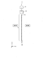
- FIGS. 3A and 3B are diagrams showing a schematic configuration of the daylighting slat 2
- FIG. 3A is a front view
- FIG. 3B is a cross-sectional view taken along the line AA ′ in FIG. 3A.
- the daylighting slat 2 includes a base material 8 having light permeability and a daylighting unit 9.
- the daylighting slat 2 bends the optical path of sunlight incident from the outside and emits it toward a predetermined direction in the room.
- the base material 8 is a long plate-like member extending in one direction (X direction).
- the base material 8 functions as a support member that supports the daylighting unit 9.
- the daylighting unit 9 is provided on the first surface 8 a of the substrate 8.
- the first surface 8a of the substrate 8 is an outdoor surface
- the second surface 8b of the substrate 8 is an indoor surface. Therefore, the daylighting unit 9 is provided outside the base material 8.
- the daylighting unit 9 may be provided on the indoor side of the base material 8.
- the lighting part 9 may be a separate body from the base material 8, or may be formed integrally.
- the length L of the daylighting slat 2 in the longitudinal direction is, for example, about 50 to 3000 mm.
- the length (slat width) W1 in the short direction of the daylighting slat 2 is, for example, about 15 to 35 mm.
- the thickness T of the daylighting slat 2 is, for example, about 0.1 to 3 mm.
- the daylighting unit 9 includes a plurality of prism structures 13 and gaps 14.
- the prism structure 13 is light transmissive.
- the space 14 is a space provided between two adjacent prism structures 13, and air exists in this space. In FIG. 3B and the subsequent drawings, only five prism structures 13 are shown, but more prism structures 13 are actually provided.
- the prism structure 13 is made of an organic material having light transmissivity and photosensitivity such as acrylic resin, epoxy resin, and silicone resin.
- a material in which a polymerization initiator, a coupling agent, a monomer, an organic solvent, or the like is mixed with these organic materials can be used.
- the polymerization initiator contains various additive components such as a stabilizer, an inhibitor, a plasticizer, a fluorescent brightening agent, a release agent, a chain transfer agent, and other photopolymerizable monomers. Also good.
- materials described in Japanese Patent No. 41299991 can be used.
- the total light transmittance of the prism structure 13 is preferably 90% or more in accordance with JIS K7361-1. Thereby, sufficient transparency can be obtained.
- the prism structure 13 extends in the longitudinal direction (x direction) of the daylighting slat 2.
- the plurality of prism structures 13 are provided side by side in the lateral direction (y direction) of the daylighting slat 2.
- the prism structure 13 is a triangular prism-shaped transparent structure. That is, the shape of the cross section perpendicular to the longitudinal direction of the prism structure 13 is a triangle.
- the prism structure 13 changes the direction of incident sunlight in the vertical plane.
- the shape of the prism structure 13 is not limited to a triangular prism shape as described later, and may be a polygonal column shape other than the triangular prism, and is not particularly limited.
- the prism structure 13 includes a first surface 13a that mainly functions as a reflecting surface that reflects incident light, and a second surface 13b that mainly functions as an incident surface on which sunlight enters. And a third surface 13c in contact with the first surface 8a of the substrate 8.
- the first surface 8 a of the base material 8 is referred to as a reference surface J of the daylighting slat 2.
- the angle ⁇ is about 51 ° to 90 °.
- the angle ⁇ is about 33 ° to 90 °.
- the angle ⁇ and the angle ⁇ need not be equal.
- the solar light L that has passed through the window glass is incident on the prism structure 13 and is emitted from the base material 8 in several ways.
- a typical route is shown in FIG. As shown in FIG. 5, when the sunlight L that has passed through the window glass enters the prism structure 13 from the second surface 13b, the sunlight L is reflected by the first surface 13a, and then enters the substrate 8, and Injected from the two surfaces 8b.
- the range of the incident angle of the light L totally reflected by the first surface 13a is the widest, the light incident on the prism structure 13 can be efficiently guided to the second surface 8b side of the substrate 8. it can. As a result, the loss of the light L incident on the prism structure 13 can be suppressed, and the intensity of the light emitted from the second surface 8b of the substrate 8 can be increased.
- the refractive index of the substrate 8 and the refractive index of the prism structure 13 are substantially equal. That is, it is desirable that the base material 8 and the prism structure 13 are integrally formed.
- the refractive index of the base material 8 and the refractive index of the prism structure 13 are greatly different, when light enters the base material 8 from the prism structure 13, the interface between the prism structure 13 and the base material 8 Unnecessary light refraction or reflection may occur. In this case, there is a possibility that problems such as failure to obtain desired lighting characteristics and a decrease in luminance may occur.
- the support mechanism 4 includes a plurality of ladder cords 16 arranged in parallel in the vertical direction (y direction), a head box 17 that supports upper end portions of the plurality of ladder cords 16, and a plurality of ladder cords 16. And an elevating bar 18 attached to the lower end of the.
- the drive mechanism 5 is accommodated in the head box 17.
- the drive mechanism 5 includes a rotating drum (not shown) that rotates each daylighting slat 9, a lifting drum (not shown) that lifts and lowers the plurality of lighting slats 9, a motor (not shown) that rotates the rotating drum and the lifting drum, and the like. .
- the control unit 6 includes a central processing unit 20 and a memory 21.
- the control unit 6 calculates the tilt angle of the daylighting slats 2 at each time by the central processing unit 20 and changes the tilt angle of the plurality of daylighting slats 2 according to the position of the sun. To control.
- the memory 21 for example, (1) correlation of light incident angle (incident angle of light with respect to the ground plane, incident angle of light with respect to the lighting surface), inclination angle of the lighting slat 2, and light emission angle, (2) Either the correlation between the incident angle of light and the inclination angle of the daylighting slat 2 or (3) the correlation between the date and time and the inclination angle of the daylighting slat 2 is stored in the form of an equation or a table.
- the memory 21 of the present embodiment corresponds to a storage unit in claims.
- the position of the sun can be automatically calculated by, for example, acquiring the latitude and longitude of the installation location by GPS, it is not necessary to prepare a correlation for each installation area.
- the orientation of the installation location can be acquired by a geomagnetic sensor, it is possible to automatically cope with a change in the orientation of the installation surface.
- the offset angle ⁇ is set according to the size of the building (for example, if the depth of the room is wide, the offset angle ⁇ is reduced, and if the depth of the room is narrow, the offset angle ⁇ is increased to illuminate the entire room. ),
- the correlation stored in the memory is different for each offset angle ⁇ .
- the memory 21 may store an information table of the daylighting apparatus 1 including the width and pitch of the daylighting slats 2 in which the daylighting apparatus 1 is installed.
- the daylighting apparatus 1 having the above-described configuration is installed on the indoor side or the outdoor side of the window glass while being suspended from the upper part of a window sash or the like.
- the daylighting slat 2 may be arranged so that the prism structure 13 side faces the indoor side, or the prism structure 13 side faces the outdoor side. May be arranged.
- the daylighting device 1 of the first embodiment at any date and time, sunlight (direct light) incident on the daylighting device 1 is moved upward or downward by an offset angle described later from a horizontal plane parallel to the floor of the room.
- the angle of inclination of the daylighting slat 2 can be controlled so as to be emitted.
- the lighting device 1 may include a remote controller for setting the offset angle.
- the user can adjust the inclination angle of the daylighting slat 2 according to the brightness and dazzling of the room using the remote controller.
- an electric light-shielding blind equipped with a remote controller is conventionally known.
- a light-shielding blind only light reflection occurs, so the relationship between the slat angle and the emission angle is approximately linear.
- the relationship between the slat angle and the emission angle is nonlinear. For example, even when it is desired to change the injection angle once, how many times the slat angle should be changed depends on the date and time.
- the daylighting apparatus 1 of the first embodiment since the correlation between the emission angle, the incident angle of light, and the slat inclination angle is known, it can be controlled to a desired emission angle throughout the year.
- a virtual plane formed by the extending direction (x direction) of the daylighting slats 2 and the arrangement direction (y direction) of the plurality of daylighting slats 2 is defined as a daylighting surface.
- the lighting surface always coincides with the vertical surface regardless of the inclination angle of the lighting slat 2.
- the angle formed between the normal direction of the reference plane J of the daylighting slat 2 and the sun direction is 0 °
- the incident height of light with respect to the plane K orthogonal to the reference plane J of the daylighting slat 2 is defined as ⁇ s_in
- the emission height of light with respect to the plane K orthogonal to the reference plane J is defined as ⁇ s_out.
- the reference plane J said here is the 1st surface 8a of the base material 8 among the lighting slats 2 as mentioned above.
- the incident height of light with respect to the horizontal plane H is defined as ⁇ h_in
- the emitted height of light with respect to the horizontal plane H is defined as ⁇ h_out.
- the horizontal plane H is a plane that coincides with the plane formed by the horizon in the horizon coordinate system. Therefore, the direction orthogonal to the horizontal plane H corresponds to the zenith direction.
- the direction of the ceiling with respect to the daylighting apparatus 1 is the zenith direction
- the direction of the floor is the nadir direction.
- the light incident height ⁇ s_in and the light exit height ⁇ s_out with respect to the plane K perpendicular to the reference plane J of the daylighting slat 2 change according to the rotation of the daylighting slat 2.
- the light incident height ⁇ h_in and the light exit height ⁇ h_out with respect to the horizontal plane H do not change even when the daylighting slat 2 rotates.
- the incident height ⁇ h_in of light with respect to the horizontal plane H corresponds to the solar altitude.
- the slat In conventional electric blinds, the slat is often made of metal, wood, or the like. Therefore, basically, the angle of the slat is controlled so that direct light is shielded, and the lighting effect is hardly obtained. On the other hand, in the lighting device 1 of the first embodiment, it is possible to efficiently capture direct light while suppressing glare.
- the horizontal plane H described below is a plane that coincides with the plane formed by the horizon in the horizon coordinate system, and is a plane parallel to the floor of the building.
- the daylighting apparatus 1 has a configuration in which the daylighting slat 2 can be tilted by the control of the control unit 6. Therefore, as shown in FIG. 6C, when the incident height ⁇ h_in of the light with respect to the horizontal plane H is 50 °, when the daylighting slat 2 is rotated and the rotation angle ⁇ of the daylighting slat 2 is 10 °, the reference plane J The incident height ⁇ s_in with respect to the plane K orthogonal to is 40 °. At this time, the injection height ⁇ s_out with respect to the plane K perpendicular to the reference plane J is 10 °. Thereby, the injection height ⁇ h_out with respect to the horizontal plane H becomes 0 °.
- the fluctuation of the solar altitude can be offset by the rotation (tilt) of the daylighting slat 2, and the back side of the room can be stably illuminated.
- the rotation angle ⁇ of the daylighting slat is referred to as a slat rotation angle ⁇ .
- the calculation method of the slat rotation angle ⁇ when the relationship of ⁇ s_out ⁇ s_in ⁇ 30 ° holds when the angle formed between the normal direction of the reference plane J of the daylighting slat 2 and the azimuth of the sun is 0 °.
- An example was described.
- this example is for demonstrating the effect of the daylighting apparatus 1 of this embodiment in an easy-to-understand manner, and when the angle formed by the normal direction of the reference plane J and the sun's direction is 0 °. Only holds.
- the daylighting apparatus 1 is installed on a side window where the floor surface of the building and the daylighting surface are in a vertical positional relationship.
- the following design can be calculated by an angle with respect to the floor surface regardless of whether or not the floor surface and the lighting surface are in a vertical positional relationship.
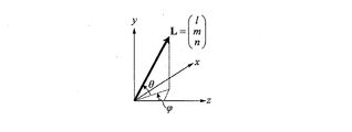
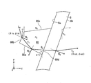
- the coordinate conversion between the orthogonal coordinate system and the horizon coordinate system is as follows. As shown in FIG. 7, the angle formed between the xz plane of the xyz orthogonal coordinate system and the vector L is ⁇ , and the angle formed between the projection of the vector L on the xz plane and the z axis is ⁇ . At this time, the coordinate conversion of the vector L from the orthogonal coordinate system to the horizon coordinate system can be expressed as in equation (5).
- the equation of the light beam in the three-dimensional space can be considered as follows.
- the incident light incident on the interface between the refractive index n A and the refractive index n B is indicated by a vector L
- the reflected light is indicated by a vector R
- the refracted light is indicated by a vector T.
- the normal vector is N.
- the normal vector N is set so that the angle formed with the incident light vector L is 90 ° or less.
- the refractive index of the substance on the emission side of the substrate is n C.
- of each light vector are refractive indexes of the medium. Specifically,
- n A and
- n B.
- is 1.
- Equation (7) is derived from the light refraction formula (Snell's law in a three-dimensional space).
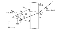
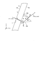
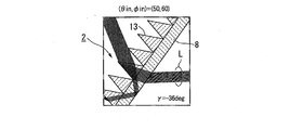
- FIG. 9 shows an optical path of light emitted from the substrate 8 after being reflected once by the first surface 13a of the prism structure 13 in a state where the daylighting slat is not rotated.
- the light that is reflected once by the first surface of the prism structure and emitted is referred to as “one-time reflected light”.
- the incident light vector is L0
- the refracted light vector on the second surface 13b is T1
- the reflected light vector on the first surface 13a is R2
- the emitted light vector from the substrate 8 is T3.
- the normal vector for the second surface 13b is N1
- the normal vector for the first surface 13a is N2
- the normal vector for the second surface 8b of the substrate 8 is N3.
- the angle formed by the first surface 13a of the prism structure 13 and the first surface 8a of the substrate 8 is ⁇
- the angle formed by the second surface 13b of the prism structure 13 and the first surface 8a of the substrate 8 is ⁇ .
- 0 ° ⁇ ⁇ 90 ° and 0 ° ⁇ ⁇ ⁇ 90 ° are satisfied.
- the prism structure is provided on the outdoor side, the light is mainly incident on the second surface 13a, reflected by the first surface 13a, and then emitted through the substrate 8. For this reason, it is preferable that light is more easily incident on the second surface 13b than the first surface 13a. Therefore, ⁇ ⁇ ⁇ is preferable.
- the incident altitude is ⁇ in
- the incident azimuth is ⁇ in
- the exit altitude is ⁇ out
- the exit azimuth is ⁇ out
- ⁇ 90 ° ⁇ ⁇ in ⁇ 90 °, ⁇ 90 ° ⁇ ⁇ in ⁇ 90 °, ⁇ 90 ° ⁇ ⁇ out ⁇ 90 ° and ⁇ 90 ° ⁇ ⁇ out ⁇ 90 ° are satisfied.
- These parameters are shown in a horizon coordinate system with the y-axis as the zenith.
- the altitude is expressed as a positive value in the counterclockwise direction with respect to the horizontal plane and as a negative value in the clockwise direction.
- the refraction light vector T1 the reflection light vector R2, and the emission light vector T3 are obtained, and the following (8), (9), ( 10) is derived.
- Equation (11) is derived from Equations (8), (9), and (10).
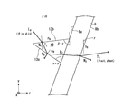
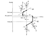
- FIG. 11 shows an optical path of one-time reflected light in a state where the daylighting slat is rotated.
- the slat rotation angle ⁇ as shown in FIG. 12, the case where the daylighting slat 2 is rotated counterclockwise is represented by a positive value, and the case where it is rotated clockwise is represented by a negative value.
- the slat rotation angle ⁇ is negative, and when the upper end of the daylighting slat 2 is rotated outward, the slat rotation angle ⁇ is positive.
- the possible range of the slat rotation angle ⁇ is ⁇ 90 ° ⁇ ⁇ 90 °.
- Equation (18) is solved for ⁇ out, and when ⁇ out is equal to or larger than the offset angle ⁇ , the light is emitted toward the horizontal direction or the ceiling side, so the following equation (19) is derived.
- by 1 ° from ⁇ 0 °. This calculation is basically performed only once when the daylighting apparatus is installed, and thereafter, a correspondence table between the date and time and the slat rotation angle ⁇ may be stored in the memory 21.
- FIG. 13 shows the optical path of one-time reflected light when different daylighting slats are rotated.
- a daylighting slat including a prism structure 80 having a quadrangular cross section perpendicular to the longitudinal direction is shown.
- the prism structure 80 includes a first surface 80a that mainly functions as a reflecting surface that reflects incident light, a second surface 80b that mainly functions as an incident surface on which sunlight is incident, and one side that is a second surface 80b. It has the 3rd surface 80c which touches, and the 4th surface 80d which contact
- Equation (23) is solved for ⁇ out, and when ⁇ out is equal to or larger than the offset angle ⁇ , the light is emitted toward the horizontal direction or the ceiling side, so the following equation (24) is derived.
- by 1 ° from ⁇ 0 °. In this example as well, this calculation may basically be performed once when the daylighting apparatus is installed, and thereafter, a correspondence table between the date and time and the slat rotation angle ⁇ may be stored in the memory 21.
- the refractive index is lower than the refractive index n B of the prism structure 80, for example, as shown in FIG.
- a low refractive index material having nA may be filled.
- the number of base materials 8 is not limited to one, and may be composed of a plurality of sheets.
- FIG. 14 shows an optical path of one-time reflected light when a daylighting slat having a prism structure 83 on the indoor side is rotated.
- FIG. 11 an example of a daylighting slat including a prism structure 83 having a triangular cross section perpendicular to the longitudinal direction is shown.
- the angle formed by the first surface 83a of the prism structure 83 and the first surface 8a of the substrate 8 is ⁇
- the angle formed by the second surface 83b of the prism structure 83 and the first surface 8a of the substrate 8 is ⁇ .
- 0 ° ⁇ ⁇ 90 ° and 0 ° ⁇ ⁇ ⁇ 90 ° are satisfied.
- the prism structure is provided on the indoor side, the light is incident mainly through the base material, reflected by the first surface 83a, and then emitted from the second surface 83b. For this reason, it is preferable that light is more easily incident on the first surface 83a than the second surface 83b. Therefore, ⁇ ⁇ ⁇ is preferable.
- the slat rotation angle ⁇ When the upper end of the daylighting slat is rotated indoors, the slat rotation angle ⁇ is positive, and when the upper end of the daylighting slat is rotated outward, the slat rotation angle ⁇ is negative.
- the normal vectors N1, N2, and N3 are expressed as the following equations (25), (26), and (27), respectively.
- Equation (28) is solved for ⁇ out, and when ⁇ out is equal to or larger than the offset angle ⁇ , the light is emitted toward the horizontal direction or the ceiling side, so the following equation (29) is derived.
- by 1 ° from ⁇ 0 °.
- the daylighting apparatus 1 of the present embodiment even if the position of the sun fluctuates throughout the year or throughout the day, direct light is stably guided to the back of the room while suppressing glare. And efficient lighting can be performed.
- the daylighting apparatus 1 for example, when the solar altitude (incident altitude of light with respect to the horizontal plane) is increased, the daylighting slat 2 is rotated, whereby the normal direction K of the substrate surface is obtained.
- the effect that the incident height can be reduced (first effect) and the effect that the emission height relative to the horizontal plane H can be reduced (second effect) can be combined to bring the light emission direction closer to the horizontal direction, Direct light can be guided to the back of the room.
- the upper side of the daylighting slat 2 is tilted inward (clockwise in FIG. 15A).
- from the emission height relative to the normal direction K of the base material surface are combined. Get closer to the direction.
- the daylighting slats 2 can be rotated only in the direction in which the upper side of the daylighting slats 2 is tilted indoors in the blind using the ladder cord. There are many. Therefore, it is desirable to satisfy the relationship of ⁇ out / ⁇ in> 0 and ⁇ out> 0.
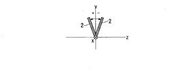
- the flat plate-shaped daylighting slat 2 when used as the daylighting slat, it can often be tilted only in one direction, but the cross-sectional shape perpendicular to the longitudinal direction is Y-shaped, Alternatively, if a T-shaped daylighting slat is used, it can be rotated in either the indoor side or the outdoor side. In this case, the slat rotation angle can be minimized regardless of whether ⁇ out / ⁇ in> 0 and ⁇ out> 0 are satisfied, or ⁇ out / ⁇ in> 0 and ⁇ out ⁇ 0. it can.
- the prism structure has a shape in which 0 ° ⁇ ⁇ 90 ° and 0 ° ⁇ ⁇ ⁇ 90 °, and the slat rotation angle ⁇ 0 in the reference posture of the daylighting slat (in this embodiment, the chamber)
- ⁇ 0 0 °
- ⁇ 0 ⁇ 20 °
- ⁇ out when ⁇ in 0 ° is ⁇ 0 (reference offset angle) It is desirable to have at least part of the combination of the angle ⁇ and the angle ⁇ satisfying 0 ° ⁇ ⁇ 0 ⁇ 5 °.
- the shape of the prism structure does not necessarily have to be a triangular prism, and may be a polygonal prism having three or more triangular prisms.
- the offset angle is 0 °, that is, when light is emitted in the horizontal direction (parallel to the floor surface), the light hits the wall facing the window, so the ceiling is difficult to brighten and the center of the room is hard to brighten. Therefore, according to the size of the room, so that the offset angle is about several degrees, that is, by allowing the light to travel obliquely upward about several degrees toward the ceiling side, from the window side of the room to the back side Can be widely illuminated.
- the distance from the ceiling to the lower end of the lighting device is H ⁇ H 0 [ m].
- the offset angle ⁇ may be determined so that this distance substantially coincides with the depth D of the room. That is, the minimum offset angle ⁇ that satisfies (H ⁇ H 0 ) / tan ⁇ ⁇ D is desirable.
- FIG. 17A it is assumed that the sunlight L incident on the first surface 13a of the prism structure 13 is not refracted but is refracted and emitted from the daylighting slat 2.
- the emission height ⁇ out decreases with an increase in the incident height ⁇ in, so that ⁇ out / ⁇ in ⁇ 0.
- FIG. 17C when the sunlight L incident on the prism structure 13 is reflected an even number of times (in this example, twice) and emitted from the daylighting slat 2, the incident height ⁇ in increases accordingly. Since the injection height ⁇ out decreases, ⁇ out / ⁇ in ⁇ 0.
- the design of the prism structure 13 is as follows: (1) having a fine structure, (2) existence of an odd number of reflection light paths, (3) range of conditions of the incident angle of light to be controlled and the slat rotation angle. It is desirable to satisfy the conditions that the intensity of the odd-numbered reflected light is greater than the intensity of the even-numbered reflected light and that (4), (2) and (3) are in the range of ⁇ out> 0.
- the present inventor performed a simulation of the light emission altitude when the altitude and direction of the sun were variously changed. The results will be described with reference to FIGS.
- a daylighting slat provided with a prismatic prism structure was used, and the refractive index was 1.65.
- the refractive index is preferably in the range of about 1.49 to 1.65.
- the lower taper angle ⁇ of the prism structure was 76 °, and the upper taper angle ⁇ was 64 °.
- the emission angle in the reference posture is 5 °
- the lower taper angle ⁇ of the prism structure was 76 °
- FIGS. 18 to 23 show simulation results of the daylighting slat having the prism structure on the outdoor side.
- the light Ld is light whose angle has changed by hitting one of the tapered surfaces of the prism structure. Therefore, by bending the light downward from the extension line in the incident direction, the light can be bent directly under the window (for example, within 1.5 m from the window), so that glare is not felt by the office worker in the room.
- FIGS. The simulation results of the daylighting slat having the prism structure on the indoor side are shown in FIGS.
- FIG. 30 the simulation result of the daylighting slat of the comparative example that does not satisfy the angle conditions of 51 ° ⁇ ⁇ ⁇ 83 ° and 33 ° ⁇ ⁇ ⁇ 90 ° is shown in FIG. 30.
- the prism structure can be properly used even if the altitude and direction of the sun change variously. It was found that the light can be emitted substantially in the horizontal direction and the glare can be suppressed by appropriately designing the slat rotation angle ⁇ of the daylighting slat.
- the daylighting slat 2 includes the daylighting unit 9 including the prism structure integrated with the base material 8 has been described.
- the lighting slat is not limited to the above-described configuration, and various configurations can be adopted.
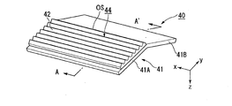
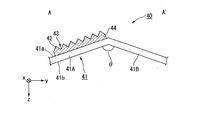
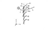
- the daylighting slat 40 of the first modification includes a base material 41 and a daylighting section 44 including a prism structure 42 that is a separate body from the base material 41.
- the base material 41 has a shape bent around a fold line OS parallel to the longitudinal direction.
- the daylighting unit 44 can be controlled in a more vertical posture, and privacy can be protected when the daylighting slat 40 is tilted as the solar altitude increases.
- the daylighting section 44 is provided in the first area 41A, and the daylighting section 44 is not provided in the second area 41B.
- region 41B of the base material 41 has a light absorptivity. Thereby, the glare at the time of rotating the lighting slat 40 can be reduced.
- the base material itself of the portion of the second region 41B may have light absorption, for example, a colored layer provided on the surface of the second region 41B, etc. Light absorptivity may be imparted.
- the angle ⁇ formed by the first region 41A and the second region 41B constituting the substrate 41 is appropriately set according to the shape of the prism structure 42 formed in the first region 41A.
- the base material 41 may be curved in a cross section perpendicular to the longitudinal direction of the base material 41 and may have a curved surface. Thereby, coloring of the lighting part by spectroscopy can be reduced. In addition, by making the incident surface or the exit surface curved instead of the reflecting surface, variation in the light exit angle can be reduced.
- the substrate 41 is made of a light transmissive resin such as a thermoplastic polymer, a thermosetting resin, or a photopolymerizable resin.
- a light transmissive resin such as a thermoplastic polymer, a thermosetting resin, or a photopolymerizable resin.
- the light transmissive resin for example, a resin made of an acrylic polymer, an olefin polymer, a vinyl polymer, a cellulose polymer, an amide polymer, a fluorine polymer, a urethane polymer, a silicone polymer, an imide polymer, or the like is used. Can do.
- polymethyl methacrylate resin PMMA
- triacetyl cellulose PET
- cycloolefin polymer COP
- PC polycarbonate
- PEN polyethylene naphthalate
- PES polyethersulfone
- PI polyimide
- the total light transmittance of the substrate 41 is preferably 90% or more according to JIS K7361-1. Thereby, sufficient transparency can be obtained.
- the configuration and shape of the prism structure 42 are as described in the first embodiment.
- the daylighting slat 40 of the first modification efficient daylighting can be performed while suppressing glare. Furthermore, when the solar altitude is low, as shown in FIG. 33, light LB that is transmitted through the prism structure 42 of the daylighting slat 40 and is emitted obliquely downward is likely to be generated. However, with the configuration of the first modification, the light LB that is transmitted through the first region 41A of the base material 41 and is emitted obliquely downward can be absorbed by the second region 41B. Thereby, glare can be suppressed.
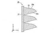
- the daylighting slat 26 according to the second modification includes a base material 27 and a plurality of prism structures 25 provided on the base material 27.
- the first surface 25a that mainly functions as a reflecting surface is a flat surface
- the second surface 25b that mainly functions as an incident surface is a curved surface.
- the daylighting slat 26 of the second modified example it is possible to perform efficient daylighting while suppressing glare by appropriately adjusting the slat rotation angle ⁇ of the daylighting slat. Furthermore, since the second surface 25b that functions as the light incident surface is a curved surface, color breakup due to wavelength dispersion can be suppressed.
- the daylighting slat 36 of the third modified example includes a daylighting sheet 37 including a prism structure 30, a low refractive index material layer 31, a hard coat layer 32, a base material layer 33, and an adhesive layer. 34 and a panel 35.
- the daylighting slat 26 of the third modified example it is possible to perform efficient daylighting while suppressing glare by appropriately adjusting the slat rotation angle ⁇ of the daylighting slat.
- the daylighting slat 85 of the fourth modified example includes a base material 8, a daylighting sheet 9 including a plurality of prism structures 13, and an anisotropic light diffusion sheet 11.
- the daylighting slat 85 is different from the above embodiment in that the anisotropic light diffusing sheet 11 is provided.
- the anisotropic light diffusion sheet 11 is bonded to the base material 8 by an adhesive layer (not shown).
- the anisotropic light diffusion sheet 11 strongly diffuses the light L sequentially emitted from the daylighting sheet 9 and the base material 8 in the horizontal direction. Specifically, the light L emitted from the substrate 8 is more extended in the direction of the plurality of prism structures 13 (X direction) than in the direction perpendicular to the direction of extension of the plurality of prism structures 13 (Y direction). ) Strongly diffuse in the direction parallel to.
- the anisotropic light diffusion sheet 11 may be composed of, for example, a lenticular lens including a plurality of cylindrical lenses.
- each cylindrical lens extends in the short side direction of the daylighting slat 85, and is arranged in parallel to each other in a direction perpendicular to the extending direction of each cylindrical lens. That is, the arrangement direction (extending direction) of the plurality of cylindrical lenses is orthogonal to the arrangement direction (extending direction) of the plurality of prism structures 13 of the daylighting sheet 9 described above.
- the lens surface of the cylindrical lens has a curvature in a horizontal plane and does not have a curvature in the vertical direction. For this reason, the cylindrical lens has strong light diffusibility in the horizontal direction and does not have light diffusibility in the vertical direction. Therefore, the light L is diffused and emitted in the horizontal direction in the anisotropic light diffusion sheet 11 while maintaining the vertical angle distribution when emitted from the daylighting sheet 9 (prism structure 13).
- the anisotropic light diffusion sheet 11 is configured separately from the daylighting sheet 9 and the base material 8.
- the anisotropic light diffusion sheet 11 may be configured integrally with the daylighting sheet 9 and the base material 8.
- the second surface side of the substrate 8 may be processed to form a plurality of cylindrical lenses integrally with the substrate 8.
- the anisotropic light diffusing sheet 11 does not necessarily need to be composed of a lenticular lens, and may be composed of, for example, a translucent sheet provided with a plurality of convex portions extending in approximately one direction.
- a daylighting slat 86 having a configuration in which the daylighting sheet 9 and the anisotropic light diffusion sheet 11 are directly bonded to each other without using the substrate 8 may be employed.
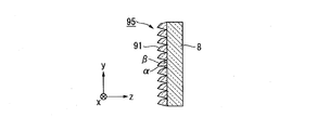
- a daylighting slat 95 of the fifth modification includes a base material 8 and a plurality of prism structures 91 having a quadrangular cross section provided on the outdoor side of the base material 8.
- the daylighting slat 96 of the sixth modification includes a base material 8 and a plurality of prism structures 92 having a quadrangular cross section provided on the outdoor side of the base material 8.
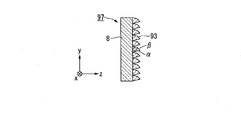
- the daylighting slat 97 of the seventh modified example includes a base material 8 and a plurality of prism structures 93 having a square cross section provided on the indoor side of the base material 8.
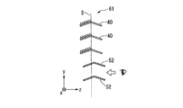
- FIG. 41 is a perspective view of the daylighting device of the second embodiment, and corresponds to FIG. 1 of the first embodiment.
- FIG. 41 and FIGS. 42A to 42C the same reference numerals are given to the same components as those used in the first embodiment, and the description thereof will be omitted.
- the daylighting device 51 of the second embodiment includes a plurality of daylighting slats 2, a plurality of light shielding slats 52, a support mechanism 4, a drive mechanism 5, and a control unit 6. .
- a plurality of light shielding slats 52 constitute a light shielding unit 53. That is, in the first embodiment, all the slats are the daylighting slats 2, whereas in the second embodiment, the plurality of slats include the daylighting slats 2 and the light shielding slats 52.
- the plurality of daylighting slats 2 are installed above the eyes of the office workers so that the indoor office workers are not dazzled because the sunlight is bent toward the ceiling of the room.
- the plurality of light shielding slats 52 are installed below the plurality of daylighting slats 2.
- the daylighting slat 2 is the same as the daylighting slat 2 of the first embodiment.
- the light shielding slat 52 is made of, for example, a metal such as aluminum or wood, and shields light.
- the shape of the light shielding slat 52 is not particularly limited as long as it can shield light.
- a diffuse transmission slat may be used instead of the light shielding slat 52.
- the diffuse transmission slat is a transparent resin plate material such as polycarbonate having light scattering properties, and diffuses and transmits light.
- the light shielding slat 52 and the diffuse transmission slat of the second embodiment correspond to the second slat in the claims.
- the plurality of light shielding slats 52 are configured such that the inclination angle of each light shielding slat 52 can be changed. In the case of the second embodiment, the plurality of light shielding slats 52 are rotated in conjunction with the plurality of daylighting slats 2 by the drive mechanism 5.
- daylighting slats 40 having a shape in which a flat plate is bent may be used.
- the plurality of daylighting slats 40 are arranged such that the first portion 41a provided with the plurality of daylighting units is parallel to the daylighting surface S.
- the sunlight L is bent by the plurality of prism structures 13 and emitted toward the back of the room.
- the plurality of light shielding slats 52 at least a part of the light shielding slats 52 is arranged in parallel to the lighting surface S.
- the plurality of daylighting slats 40 do not rotate when the solar altitude increases, it is difficult for the sunlight L to illuminate only the vicinity of the window and illuminate the back side of the room.
- the plurality of daylighting slats 40 rotate in a direction in which the upper end side is inclined indoors with respect to the daylighting surface S.
- the sunlight L can illuminate the back side of the room.
- the plurality of light shielding slats 52 rotate in a direction in which the upper end side is inclined inward with respect to the lighting surface S in conjunction with the plurality of daylighting slats 40.
- the plurality of daylighting slats 40 include first portions 41a provided with a plurality of prism structures 13. It rotates to a position close to perpendicular to the lighting surface S.
- the plurality of light shielding slats 52 are also rotated to a position close to the perpendicular to the lighting surface S. Thereby, the viewability of the daylighting device 51 is improved, and the office worker can visually recognize the outdoor scenery.
- the daylighting device 51 since the daylighting device 51 includes the light shielding slats 52, glare can be more sufficiently suppressed. Further, since the plurality of light shielding slats 52 are rotated in conjunction with the plurality of daylighting slats 2 and 40, it is not necessary to separately provide a drive mechanism for the light shielding slats 52, and the configuration of the daylighting device 51 can be prevented from becoming complicated. .
- the plurality of light shielding slats 52 may be configured to rotate independently of the plurality of daylighting slats 2. In this case, the plurality of light shielding slats 52 may be configured to rotate automatically or may be configured to rotate manually. When the plurality of light shielding slats 52 are configured to rotate independently, the number of drive mechanisms is increased, but the light shielding slats 52 can be tilted more indoors to the direct shielding angle. Thereby, the amount of light collection can be increased. In the present embodiment, the plurality of light shielding slats 52 change the tilt angle, but may not change the tilt angle.
- FIG. 43 is a perspective view of the daylighting device of the third embodiment, corresponding to FIG. 1 of the first embodiment.
- FIG. 43 and FIGS. 44A to 44D the same components as those used in the first embodiment are denoted by the same reference numerals, and description thereof is omitted.
- the daylighting device 61 of the third embodiment includes a plurality of daylighting slats 2, a plurality of light shielding slats 52, a support mechanism 4, a first drive mechanism 63, and a second drive mechanism 64. And a direct light detection unit 65 and a control unit 66.
- the first drive mechanism 63 and the second drive mechanism 64 are accommodated in the head box 17.
- the plurality of daylighting slats 2 are configured to be rotatable by the first drive mechanism 63, and the inclination angle of each daylighting slat 2 is configured to be changeable.
- the plurality of light shielding slats 52 are configured to be rotatable by the second drive mechanism 64, and the inclination angle of each light shielding slat 52 is configured to be changeable. That is, the daylighting device 61 of the third embodiment includes a second drive mechanism 64 that drives the light shielding slats 52 independently of the driving of the daylighting slats 2.
- the configurations of the daylighting slats 2 and the light shielding slats 52 are the same as those in the first embodiment and the second embodiment.
- the direct light detector 65 detects the presence or absence of direct light in the building where the daylighting device 61 is installed or in the peripheral part of the building.
- the direct light detection unit 65 may detect any amount of solar radiation, luminance, illuminance, etc., as long as the daylighting device 61 can detect the presence or absence of direct light received directly from the sun. Can be used.
- the installation position of the direct light detection unit 65 may be any one of, for example, a rooftop of a building, an outer wall, a window, and a room. For example, when a plurality of daylighting devices 61 are installed in one building, the plurality of daylighting devices 61 may also serve as one direct light detection unit 65.
- the direct light detection unit 65 for example, (1) a sun tracking type illuminance sensor or solar radiation amount sensor, (2) a fisheye camera, or the like can be used.
- (1) includes a first illuminance meter that tracks the sun and a second illuminance meter that measures the illuminance by the sky light excluding the periphery of the sun, and whether it is clear or cloudy depending on the difference between the measured values of each illuminometer And control the slats.
- a sky image of the whole sky is picked up by a fish-eye camera, and solar radiation is applied to a plurality of areas obtained by dividing the whole sky based on at least one index of luminance value, R value, B value, and G value. Judge the condition of the weather.
- daylighting slats 40 having a shape obtained by bending a flat plate may be used.
- the control unit 66 controls the inclination angle of the daylighting slat 2 based on the direct solar radiation amount detected by the direct solar radiation amount detection unit 65. For example, when the control unit 66 determines that the amount of direct solar radiation is greater than a predetermined threshold value on a clear day, as shown in FIGS. 44A and 44B, a plurality of daylighting slats 40 according to the solar altitude, as in the second embodiment. Is controlled to an inclination angle so that light can be guided to the back of the room, while the plurality of light shielding slats 52 are controlled to be a solar radiation shielding angle or to be fully closed.
- control unit 66 determines that the amount of direct solar radiation is below a predetermined threshold during cloudy or rainy weather, for example, as shown in FIG. 44C, the lighting slats 40 and the light shielding slats 52 are both leveled. The amount of light extraction can be increased while ensuring the view.
- the control unit 66 may control the inclination angle of the daylighting slat 40 to be a predetermined value when it is determined that the amount of direct solar radiation is not more than a predetermined threshold.
- the lighting device 61 not only direct sunlight but also reflected light from surrounding buildings may reach the lighting device 61.
- the memory 21 of the control unit 66 stores the position and height of the surrounding building, the installation position information of the plurality of daylighting devices 61 in the building, etc., it is determined whether or not there is reflected light. Judgment can be made. This reflected light amount may be added to the determination of opening / closing of the slats.
- the same effects as those in the first and second embodiments can be obtained, such as providing a daylighting device that can achieve both glare suppression and efficient daylighting.
- control unit 66 controls the inclination angles of the daylighting slats 2 and 40 and the shading slats 52 based on the amount of direct solar radiation, efficient lighting and glare according to the amount of direct solar radiation are achieved. In addition to being able to be suppressed, it is possible to ensure the viewability especially in cloudy weather and rainy weather. Further, since the daylighting slats 2 and 40 and the light shielding slats 52 rotate independently, it is possible to control the daylighting slats 2 and 40 and the light shielding slats 52 to have optimum tilt angles.
- FIGS. 45A to 45C The basic configuration of the daylighting device of this embodiment is the same as that of the second embodiment, and the operations of a plurality of daylighting slats are different from those of the second embodiment.
- FIG. 45A is a first diagram for describing an example of an operation method of the daylighting device according to the fourth embodiment.
- FIG. 45B is a second diagram for explaining an example of the operation method of the daylighting device according to the fourth embodiment.
- FIG. 45C is a third diagram for describing an example of the operation method of the daylighting device of the fourth embodiment.
- 45A to 45C the same reference numerals are given to the same components as those used in the second embodiment, and the description thereof will be omitted.
- the daylighting apparatus 101 of the fourth embodiment includes a plurality of daylighting slats 40, a plurality of light shielding slats 52, a support mechanism 4, a drive mechanism 5, and a control unit 6. . That is, in the fourth embodiment, as in the second embodiment, the plurality of slats include the daylighting slats 40 and the light shielding slats 52.
- the plurality of daylighting slats 40 are installed above the eyes of the office worker in the room.
- the plurality of light shielding slats 52 are installed below the plurality of daylighting slats 40.
- the configuration of the daylighting slat 40 itself is the same as that of the daylighting slat 2 of the first embodiment.
- the daylighting slat 40 may be manually rotatable or may be automatically rotated by the drive mechanism 5.
- the configuration of the light shielding slat 52 itself is the same as that of the light shielding slat 52 of the second embodiment. In the present embodiment, the light shielding slat 52 is configured to be automatically rotated by the drive mechanism 5.
- the drive mechanism 5 drives at least one of the daylighting slats 40 or the light shielding slats 52. Moreover, the control part 6 controls the drive mechanism 5 so that the inclination-angle of at least one slat may be changed according to the position of the sun.
- the plurality of daylighting slats 40 are arranged such that the first portions 41a provided with a plurality of daylighting units are parallel to the daylighting surface S. It is fixed in the state. That is, at the time of fine weather, the control unit 6 does not perform control to change the inclination angle of the daylighting slat 40. As a result, the sunlight L is bent by the plurality of prism structures 13 and emitted toward the back of the room.
- the plurality of light shielding slats 52 are controlled by the control unit 6 so that the inclination angle becomes the solar radiation shielding angle according to the position of the sun.
- the plurality of daylighting slats 40 may be arranged such that the first portion 41 a provided with the plurality of daylighting units is parallel to the daylighting surface S.
- the plurality of daylighting slats 40 may be arranged such that the first portion 41 a provided with the plurality of daylighting units is positioned near to the daylighting surface S.
- the plurality of daylighting slats 40 may be arranged so as to be at an intermediate position between FIGS. 45B and 45C. Further, the position of the daylighting slat 40 may be manually adjusted during cloudy weather or may be controlled electrically.
- the plurality of light shielding slats 52 are controlled by the control unit 6 so as to be in a position close to perpendicular to the lighting surface S, for example.
- the same effect as that of the first embodiment can be obtained, in which a daylighting device capable of achieving both glare suppression and efficient daylighting can be provided.
- the daylighting slat 40 has a prism structure that has a large contribution of even-numbered reflected light (refracted light, twice-reflected light). May become glare.
- the daylighting slat 40 needs to be installed above the office worker's line of sight, but in a building with a low ceiling, the daylighting slat 40 may not be sufficiently arranged above the office worker's line of sight.
- the amount of light can be increased by electrically controlling the light shielding slat 52 instead of the daylighting slat 40. .
- movement for raising light collection amount according to the weather or the outdoor brightness becomes high.
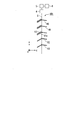
- FIG. 46 is a perspective view of the daylighting system of the fifth embodiment.
- FIG. 47 is a sectional view of the daylighting system. 46 and 47, the same reference numerals are given to the same components as those used in the first embodiment, and the description thereof will be omitted.
- the daylighting system 71 includes a daylighting device 51 and a multilayer glass 74.
- the multi-layer glass 74 has a configuration in which a pair of glass plates are arranged to face each other with a gap therebetween.
- the daylighting device 51 is provided between the outdoor side glass plate 72 and the indoor side glass plate 73 constituting the plurality of glasses 74.
- 46 and 47 show an example of the daylighting device 51 of the second embodiment having the daylighting slats 2 and the light shielding slats 52, any one of the daylighting devices of the first to third embodiments may be used.
- the daylighting system 71 of the present embodiment includes the daylighting devices of the first to fourth embodiments, glare suppression and efficient daylighting can be realized.
- the daylighting device 51 is installed inside the multilayer glass 74 and is protected from moisture, impact, and the like, which are external factors that cause deformation and alteration of the slats, the daylighting slats 2 and the light shielding slats 52 are hardly deteriorated. The lighting effect and the light shielding effect can be sufficiently maintained. Further, since the window and the daylighting device 51 are integrated as the daylighting system 71, the difference in appearance due to the presence or absence of the daylighting device 51 is reduced, and the uniformity of the external appearance of the building is improved.
- FIG. 48 is a diagram showing a room model 2000 including a daylighting device and an illumination dimming system, and is a cross-sectional view taken along the line AA ′ of FIG.
- FIG. 49 is a plan view showing the ceiling of the room model 2000.
- the ceiling material constituting the ceiling 2003a of the room 2003 into which sunlight is introduced may have high light reflectivity.
- a light-reflective ceiling material 2003A is installed on the ceiling 2003a of the room 2003 as a light-reflective ceiling material.
- the light-reflective ceiling material 2003A promotes introduction of external light from the daylighting apparatus 2010 installed in the window 2002 toward the back of the room.
- the light-reflective ceiling material 2003A is installed on the ceiling 2003a near the window. Specifically, it is installed in a predetermined area E (an area about 3 m from the window 2002) of the ceiling 2003a.
- the light-reflective ceiling material 2003A is efficient for the sunlight introduced into the room through the window 2002 in which the daylighting device 2010 of any of the above-described embodiments is installed. Lead well. Sunlight introduced from the daylighting apparatus 2010 toward the indoor ceiling 2003a is reflected by the light-reflective ceiling material 2003A and changes its direction to illuminate the desk surface 2005a of the desk 2005 placed in the interior of the room. The effect of brightening the desk top surface 2005a is exhibited.
- the light-reflective ceiling material 2003A may be diffusely reflective or specularly reflective, but has the effect of brightening the desk top surface 2005a of the desk 2005 placed in the interior of the room, and is in the room. In order to achieve both the effects of suppressing glare light that is unpleasant for humans, it is preferable that the characteristics of both are appropriately combined.
- the vicinity of the window 2002 often has a sufficient amount of light. Therefore, by using the light-reflective ceiling material 2003A as described above, the light incident on the ceiling (region E) near the window can be distributed toward the back of the room where the amount of light is small compared to the window.
- the light-reflective ceiling material 2003A is formed by embossing a metal plate such as aluminum with unevenness of about several tens of micrometers, or by depositing a metal thin film such as aluminum on the surface of a resin substrate on which similar unevenness is formed. Can be created. Or the unevenness
- the light distribution characteristics of light and the distribution of light in the room can be controlled.
- the light reflected by the light-reflective ceiling material 2003A is in the left-right direction of the window 2002 (direction intersecting the longitudinal direction of the unevenness). spread.
- the light reflecting ceiling material 2003A diffuses light in the horizontal direction and reflects it toward the back of the room. be able to.
- the daylighting device 2010 is used as part of the illumination dimming system in the room 2003.
- the lighting dimming system includes, for example, a lighting device 2010, a plurality of indoor lighting devices 2007, a solar radiation adjusting device 2008 installed in a window, a control system thereof, and a light-reflective ceiling material 2003A installed on a ceiling 2003a. And the constituent members of the entire room including
- the window 2002 of the room 2003 is provided with a daylighting device 2010, a daylighting slat is arranged on the upper side, and a light shielding slat 2008 is arranged on the lower side.
- the daylighting apparatus of the second embodiment is used as the daylighting apparatus 2010, but is not limited thereto.
- a plurality of indoor lighting devices 2007 are arranged in a grid in the left-right direction (Y direction) of the window 2002 and the depth direction (X direction) of the room.
- the plurality of indoor lighting devices 2007 together with the daylighting device 2010 constitute an entire lighting system of the room 2003.
- the indoor lighting devices 2007 are arranged in a grid pattern with an interval P of 1.8 m in the horizontal direction (Y direction) and the depth direction (X direction) of the ceiling 2003a. More specifically, 50 indoor lighting devices 2007 are arranged in 10 rows (Y direction) ⁇ 5 columns (X direction).
- the indoor lighting device 2007 includes an indoor lighting fixture 2007a, a brightness detection unit 2007b, and a control unit 2007c, and the indoor lighting fixture 2007a has a configuration in which the brightness detection unit 2007b and the control unit 2007c are integrated. .
- the indoor lighting device 2007 may include a plurality of indoor lighting fixtures 2007a and a plurality of brightness detection units 2007b. However, one brightness detection unit 2007b is provided for each indoor lighting device 2007a.
- the brightness detection unit 2007b receives the reflected light of the irradiated surface illuminated by the indoor lighting fixture 2007a, and detects the illuminance of the irradiated surface.
- the brightness detector 200b detects the illuminance of the desk surface 2005a of the desk 2005 placed indoors.
- the control units 2007c provided one by one in the room lighting device 2007 are connected to each other.
- Each indoor lighting device 2007 is configured such that the illuminance of the desk top surface 2005a detected by each brightness detection unit 2007b becomes a constant target illuminance L 0 (for example, average illuminance: 750 lx) by the control units 2007c connected to each other.
- the feedback control is performed to adjust the light output of the LED lamp of each indoor lighting fixture 2007a.
- FIG. 50 is a graph showing the relationship between the illuminance of light (natural light) collected indoors by the daylighting device and the illuminance (illumination dimming system) by the indoor lighting device.
- the vertical axis represents the illuminance (lx) on the desk surface
- the horizontal axis represents the distance (m) from the window.
- the broken line in a figure shows indoor target illumination intensity. ( ⁇ : Illuminance by lighting device, ⁇ : Illuminance by indoor lighting device, ⁇ : Total illumination)
- the desk surface illuminance caused by the light collected by the lighting device 2010 is brighter in the vicinity of the window, and the effect becomes smaller as the distance from the window increases.
- the daylighting apparatus 2010 is applied, such an illuminance distribution in the depth direction of the room is generated by natural daylighting from a window in the daytime. Therefore, the daylighting device 2010 is used in combination with the indoor lighting device 2007 that compensates for the illuminance distribution in the room.
- the daylighting device 2010 and the illumination dimming system indoor lighting device 2007
- the daylighting device may be a remote controller (input unit) that inputs the posture of the daylighting slat from the outside. May be provided.
- the control unit controls the tilt angle of the daylighting slat based on the signal input from the remote controller.
- One embodiment of the present invention can be used in a daylighting apparatus and a daylighting system for taking outside light such as sunlight indoors.
Landscapes
- Engineering & Computer Science (AREA)
- Structural Engineering (AREA)
- Architecture (AREA)
- Civil Engineering (AREA)
- General Engineering & Computer Science (AREA)
- Life Sciences & Earth Sciences (AREA)
- Sustainable Development (AREA)
- Non-Portable Lighting Devices Or Systems Thereof (AREA)
- Blinds (AREA)
- Optical Elements Other Than Lenses (AREA)
- Arrangement Of Elements, Cooling, Sealing, Or The Like Of Lighting Devices (AREA)
Abstract
Un dispositif d'éclairage naturel d'un mode de réalisation de la présente invention comprend : une première plaque de transmission de lumière pour courber le trajet lumineux de lumière incidente provenant de l'extérieur et projeter la lumière dans une direction spécifique à l'intérieur ; un premier mécanisme d'entraînement pour entraîner la première plaque ; et une unité de commande pour commander le premier mécanisme d'entraînement de façon à changer l'angle d'inclinaison de la première plaque selon la position du soleil.
Priority Applications (2)
| Application Number | Priority Date | Filing Date | Title |
|---|---|---|---|
| US16/096,260 US10538964B2 (en) | 2016-04-27 | 2017-04-26 | Daylighting device and daylighting system |
| JP2018514665A JPWO2017188318A1 (ja) | 2016-04-27 | 2017-04-26 | 採光装置および採光システム |
Applications Claiming Priority (2)
| Application Number | Priority Date | Filing Date | Title |
|---|---|---|---|
| JP2016-089662 | 2016-04-27 | ||
| JP2016089662 | 2016-04-27 |
Publications (1)
| Publication Number | Publication Date |
|---|---|
| WO2017188318A1 true WO2017188318A1 (fr) | 2017-11-02 |
Family
ID=60159773
Family Applications (1)
| Application Number | Title | Priority Date | Filing Date |
|---|---|---|---|
| PCT/JP2017/016558 Ceased WO2017188318A1 (fr) | 2016-04-27 | 2017-04-26 | Dispositif d'éclairage naturel et système d'éclairage naturel |
Country Status (3)
| Country | Link |
|---|---|
| US (1) | US10538964B2 (fr) |
| JP (1) | JPWO2017188318A1 (fr) |
| WO (1) | WO2017188318A1 (fr) |
Cited By (3)
| Publication number | Priority date | Publication date | Assignee | Title |
|---|---|---|---|---|
| KR102159829B1 (ko) * | 2020-04-08 | 2020-09-24 | 주식회사리소스랩 | 조도센서없이 집광채광루버와 연동하여 동작하는 조명제어 시스템 |
| KR20210000416A (ko) * | 2019-06-25 | 2021-01-05 | 공주대학교 산학협력단 | 불쾌 글레어 제거 기능을 가지는 조명 제어 시스템 및 방법 |
| US20210140232A1 (en) * | 2018-07-26 | 2021-05-13 | Ecole Polytechnique Federale De Lausanne (Epfl) | Shading device |
Families Citing this family (5)
| Publication number | Priority date | Publication date | Assignee | Title |
|---|---|---|---|---|
| US11187035B2 (en) | 2004-05-06 | 2021-11-30 | Mechoshade Systems, Llc | Sky camera virtual horizon mask and tracking solar disc |
| US10619415B2 (en) | 2004-05-06 | 2020-04-14 | Mechoshade Systems, Llc | Sky camera system utilizing circadian information for intelligent building control |
| WO2017131012A1 (fr) * | 2016-01-29 | 2017-08-03 | シャープ株式会社 | Store d'éclairage naturel, dispositif d'éclairage naturel et système d'éclairage |
| WO2022225894A1 (fr) * | 2021-04-19 | 2022-10-27 | Nortrup Edward H | Store de fenêtre lumineux |
| JP7837265B2 (ja) * | 2022-11-09 | 2026-03-30 | 株式会社有沢製作所 | スラット、ブラインド、及びプロジェクションシステム |
Citations (9)
| Publication number | Priority date | Publication date | Assignee | Title |
|---|---|---|---|---|
| JPH07307106A (ja) * | 1994-05-13 | 1995-11-21 | Matsushita Electric Ind Co Ltd | 昼光制御装置 |
| JP2000096956A (ja) * | 1998-09-22 | 2000-04-04 | Toso Co Ltd | 電動ブラインドの制御装置 |
| JP2011196177A (ja) * | 2011-06-08 | 2011-10-06 | Nichibei Co Ltd | 電動ブラインドのスラット角度制御装置 |
| JP2014044331A (ja) * | 2012-08-27 | 2014-03-13 | 3M Innovative Properties Co | 太陽光導光装置 |
| US20140111851A1 (en) * | 2012-10-19 | 2014-04-24 | Extend Optronics Corp. | Apparatus mounted with heat-insulation light-guide film |
| WO2015076245A1 (fr) * | 2013-11-25 | 2015-05-28 | シャープ株式会社 | Dispositif d'éclairage naturel et lamelle d'éclairage naturel |
| WO2015098940A1 (fr) * | 2013-12-25 | 2015-07-02 | シャープ株式会社 | Élément laissant passer la lumière naturelle, vitre, store et persienne laissant passer la lumière naturelle |
| JP2015138747A (ja) * | 2014-01-24 | 2015-07-30 | スタンレー電気株式会社 | 照明装置 |
| WO2016002869A1 (fr) * | 2014-07-02 | 2016-01-07 | シャープ株式会社 | Latte d'éclairage utilisant la lumière du jour et dispositif d'éclairage utilisant la lumière du jour |
Family Cites Families (35)
| Publication number | Priority date | Publication date | Assignee | Title |
|---|---|---|---|---|
| US4799526A (en) * | 1986-06-27 | 1989-01-24 | Wausau Metals Corporation | Blind with light-transmitting slats |
| US4841672A (en) * | 1986-07-04 | 1989-06-27 | Siemens Aktiengesellschaft | Device for protection from the sun |
| US6239910B1 (en) * | 1999-02-12 | 2001-05-29 | Architectural Energy Corporation | Mini-optical light shelf daylighting system |
| US6714352B2 (en) * | 1999-02-12 | 2004-03-30 | Architectural Energy Corporation | Mini-optical light shelf daylighting system |
| US6561254B1 (en) * | 2002-03-13 | 2003-05-13 | Tai-Ping Liu | Slat angle adjusting device for a venetian blind |
| US7481552B2 (en) * | 2004-06-18 | 2009-01-27 | Abl Ip Holding Llc | Light fixture having a reflector assembly and a lens assembly for same |
| WO2006055872A2 (fr) * | 2004-11-17 | 2006-05-26 | Fusion Optix, Inc. | Dispositif d'eclairage perfectionne |
| US8430548B1 (en) * | 2004-11-17 | 2013-04-30 | Fusion Optix, Inc. | Enhanced light fixture with volumetric light scattering |
| US20080202703A1 (en) * | 2007-02-28 | 2008-08-28 | Ian Robert Edmonds | Daylighting system comprising light re-direction elements in a Venetian blind |
| TWI417485B (zh) * | 2009-08-18 | 2013-12-01 | Chi Lin Technology Co Ltd | 導光膜片 |
| US8824050B2 (en) * | 2012-04-06 | 2014-09-02 | Svv Technology Innovations, Inc. | Daylighting fabric and method of making the same |
| US8873146B2 (en) * | 2012-11-09 | 2014-10-28 | SerraLux Inc. | Attachment methods for daylighting films |
| JP6111646B2 (ja) | 2012-12-19 | 2017-04-12 | 大日本印刷株式会社 | 採光装置、建物 |
| US10641448B2 (en) * | 2013-03-21 | 2020-05-05 | Dai Nippon Printing Co., Ltd. | Daylighting sheet, daylighting panel and roll-up daylighting screen |
| US9366403B2 (en) * | 2013-03-21 | 2016-06-14 | Dai Nippon Printing Co., Ltd. | Daylighting sheet, daylighting panel, roll-up daylighting screen and method of manufacturing daylighting sheet |
| JP6165512B2 (ja) * | 2013-06-14 | 2017-07-19 | 大日本印刷株式会社 | 採光システム |
| US9863593B2 (en) * | 2013-11-13 | 2018-01-09 | Sharp Kabushiki Kaisha | Daylighting film |
| US9857041B2 (en) * | 2014-04-08 | 2018-01-02 | Sharp Kabushiki Kaisha | Daylighting device |
| WO2015174401A1 (fr) * | 2014-05-12 | 2015-11-19 | シャープ株式会社 | Dispositif d'éclairage naturel |
| EP3156829B1 (fr) * | 2014-06-16 | 2019-10-16 | Sharp Kabushiki Kaisha | Élément d'éclairage naturel, procédé de fabrication d'élément d'éclairage naturel, dispositif d'éclairage naturel, et procédé d'installation d'élément d'éclairage naturel |
| US10222016B2 (en) * | 2014-06-30 | 2019-03-05 | Sharp Kabushiki Kaisha | Daylighting member, daylighting apparatus, roll screen, and blind |
| JP6667448B2 (ja) * | 2014-10-24 | 2020-03-18 | シャープ株式会社 | 採光装置 |
| US20170314752A1 (en) * | 2014-10-28 | 2017-11-02 | Sharp Kabushiki Kaisha | Daylighting device and daylighting system |
| JP6715183B2 (ja) * | 2014-12-04 | 2020-07-01 | シャープ株式会社 | 採光装置 |
| CN107532790A (zh) * | 2015-04-30 | 2018-01-02 | 夏普株式会社 | 采光系统 |
| RU2017140781A (ru) * | 2015-04-30 | 2019-05-31 | Шарп Кабусики Кайся | Ламель дневного освещения и устройство дневного освещения |
| WO2016175149A1 (fr) * | 2015-04-30 | 2016-11-03 | シャープ株式会社 | Dispositif et système d'éclairage |
| CN107709874A (zh) * | 2015-06-24 | 2018-02-16 | 夏普株式会社 | 采光装置 |
| JP6670051B2 (ja) * | 2015-07-06 | 2020-03-18 | 株式会社オービックビジネスコンサルタント | 情報処理装置、情報処理方法、およびプログラム |
| CN107850278A (zh) * | 2015-08-04 | 2018-03-27 | 夏普株式会社 | 采光部件、采光装置以及采光部件的设置方法 |
| JPWO2017038847A1 (ja) * | 2015-09-01 | 2018-06-14 | シャープ株式会社 | 採光システム、採光方法、および建築物 |
| JP6207030B2 (ja) * | 2015-10-07 | 2017-10-04 | 株式会社 マテリアルハウス | 採光構造 |
| WO2017061554A1 (fr) * | 2015-10-09 | 2017-04-13 | シャープ株式会社 | Élément d'éclairage naturel, procédé de fabrication d'un élément d'éclairage naturel, et appareil d'éclairage naturel |
| US20180313141A1 (en) * | 2015-11-02 | 2018-11-01 | Sharp Kabushiki Kaisha | Daylighting device |
| WO2017131012A1 (fr) * | 2016-01-29 | 2017-08-03 | シャープ株式会社 | Store d'éclairage naturel, dispositif d'éclairage naturel et système d'éclairage |
-
2017
- 2017-04-26 WO PCT/JP2017/016558 patent/WO2017188318A1/fr not_active Ceased
- 2017-04-26 US US16/096,260 patent/US10538964B2/en not_active Expired - Fee Related
- 2017-04-26 JP JP2018514665A patent/JPWO2017188318A1/ja active Pending
Patent Citations (9)
| Publication number | Priority date | Publication date | Assignee | Title |
|---|---|---|---|---|
| JPH07307106A (ja) * | 1994-05-13 | 1995-11-21 | Matsushita Electric Ind Co Ltd | 昼光制御装置 |
| JP2000096956A (ja) * | 1998-09-22 | 2000-04-04 | Toso Co Ltd | 電動ブラインドの制御装置 |
| JP2011196177A (ja) * | 2011-06-08 | 2011-10-06 | Nichibei Co Ltd | 電動ブラインドのスラット角度制御装置 |
| JP2014044331A (ja) * | 2012-08-27 | 2014-03-13 | 3M Innovative Properties Co | 太陽光導光装置 |
| US20140111851A1 (en) * | 2012-10-19 | 2014-04-24 | Extend Optronics Corp. | Apparatus mounted with heat-insulation light-guide film |
| WO2015076245A1 (fr) * | 2013-11-25 | 2015-05-28 | シャープ株式会社 | Dispositif d'éclairage naturel et lamelle d'éclairage naturel |
| WO2015098940A1 (fr) * | 2013-12-25 | 2015-07-02 | シャープ株式会社 | Élément laissant passer la lumière naturelle, vitre, store et persienne laissant passer la lumière naturelle |
| JP2015138747A (ja) * | 2014-01-24 | 2015-07-30 | スタンレー電気株式会社 | 照明装置 |
| WO2016002869A1 (fr) * | 2014-07-02 | 2016-01-07 | シャープ株式会社 | Latte d'éclairage utilisant la lumière du jour et dispositif d'éclairage utilisant la lumière du jour |
Cited By (5)
| Publication number | Priority date | Publication date | Assignee | Title |
|---|---|---|---|---|
| US20210140232A1 (en) * | 2018-07-26 | 2021-05-13 | Ecole Polytechnique Federale De Lausanne (Epfl) | Shading device |
| US12416201B2 (en) * | 2018-07-26 | 2025-09-16 | Ecole Polytechnique Federale De Lausanne (Epfl) | Shading device |
| KR20210000416A (ko) * | 2019-06-25 | 2021-01-05 | 공주대학교 산학협력단 | 불쾌 글레어 제거 기능을 가지는 조명 제어 시스템 및 방법 |
| KR102242141B1 (ko) * | 2019-06-25 | 2021-04-20 | 공주대학교 산학협력단 | 불쾌 글레어 제거 기능을 가지는 조명 제어 시스템 및 방법 |
| KR102159829B1 (ko) * | 2020-04-08 | 2020-09-24 | 주식회사리소스랩 | 조도센서없이 집광채광루버와 연동하여 동작하는 조명제어 시스템 |
Also Published As
| Publication number | Publication date |
|---|---|
| JPWO2017188318A1 (ja) | 2019-03-14 |
| US20190162020A1 (en) | 2019-05-30 |
| US10538964B2 (en) | 2020-01-21 |
Similar Documents
| Publication | Publication Date | Title |
|---|---|---|
| WO2017188318A1 (fr) | Dispositif d'éclairage naturel et système d'éclairage naturel | |
| RU2666131C2 (ru) | Световое устройство | |
| CN105637390B (zh) | 采光部件、采光器和采光部件的设置方法 | |
| JP6642872B2 (ja) | 採光部材、採光装置、ロールスクリーン及びブラインド | |
| CN107741610A (zh) | 采光膜、窗玻璃、卷帘和采光百叶窗 | |
| WO2016002869A1 (fr) | Latte d'éclairage utilisant la lumière du jour et dispositif d'éclairage utilisant la lumière du jour | |
| US20180291681A1 (en) | Daylighting member, method for manufacturing daylighting member, and daylighting apparatus | |
| WO2015076245A1 (fr) | Dispositif d'éclairage naturel et lamelle d'éclairage naturel | |
| WO2016175203A1 (fr) | Latte d'éclairage naturel et dispositif d'éclairage naturel | |
| US20190041017A1 (en) | Daylighting blind, daylighting device, and lighting system | |
| WO2016175207A1 (fr) | Système d'éclairage naturel | |
| WO2017038847A1 (fr) | Système et procédé d'éclairage naturel et bâtiment | |
| EP3372889A1 (fr) | Dispositif d'éclairage naturel | |
| JP2016091941A (ja) | 採光装置 | |
| JP6492357B2 (ja) | 採光システムおよび天井構造体 | |
| JP6684709B2 (ja) | 採光装置 | |
| JP6757467B2 (ja) | 採光装置 | |
| WO2018101393A1 (fr) | Système d'éclairage naturel | |
| JPWO2018066264A1 (ja) | 採光スラット及び採光装置 | |
| WO2018079709A1 (fr) | Store tamisant, dispositif d'éclairage naturel et système d'éclairage |
Legal Events
| Date | Code | Title | Description |
|---|---|---|---|
| ENP | Entry into the national phase |
Ref document number: 2018514665 Country of ref document: JP Kind code of ref document: A |
|
| NENP | Non-entry into the national phase |
Ref country code: DE |
|
| 121 | Ep: the epo has been informed by wipo that ep was designated in this application |
Ref document number: 17789600 Country of ref document: EP Kind code of ref document: A1 |
|
| 122 | Ep: pct application non-entry in european phase |
Ref document number: 17789600 Country of ref document: EP Kind code of ref document: A1 |