WO2017189306A1 - 3-dimensional printing - Google Patents
3-dimensional printing Download PDFInfo
- Publication number
- WO2017189306A1 WO2017189306A1 PCT/US2017/028413 US2017028413W WO2017189306A1 WO 2017189306 A1 WO2017189306 A1 WO 2017189306A1 US 2017028413 W US2017028413 W US 2017028413W WO 2017189306 A1 WO2017189306 A1 WO 2017189306A1
- Authority
- WO
- WIPO (PCT)
- Prior art keywords
- dopant
- layer
- particles
- fusing
- printed
- Prior art date
- Legal status (The legal status is an assumption and is not a legal conclusion. Google has not performed a legal analysis and makes no representation as to the accuracy of the status listed.)
- Ceased
Links
Classifications
-
- B—PERFORMING OPERATIONS; TRANSPORTING
- B29—WORKING OF PLASTICS; WORKING OF SUBSTANCES IN A PLASTIC STATE IN GENERAL
- B29C—SHAPING OR JOINING OF PLASTICS; SHAPING OF MATERIAL IN A PLASTIC STATE, NOT OTHERWISE PROVIDED FOR; AFTER-TREATMENT OF THE SHAPED PRODUCTS, e.g. REPAIRING
- B29C64/00—Additive manufacturing, i.e. manufacturing of three-dimensional [3D] objects by additive deposition, additive agglomeration or additive layering, e.g. by 3D printing, stereolithography or selective laser sintering
- B29C64/10—Processes of additive manufacturing
- B29C64/165—Processes of additive manufacturing using a combination of solid and fluid materials, e.g. a powder selectively bound by a liquid binder, catalyst, inhibitor or energy absorber
-
- B—PERFORMING OPERATIONS; TRANSPORTING
- B33—ADDITIVE MANUFACTURING TECHNOLOGY
- B33Y—ADDITIVE MANUFACTURING, i.e. MANUFACTURING OF THREE-DIMENSIONAL [3D] OBJECTS BY ADDITIVE DEPOSITION, ADDITIVE AGGLOMERATION OR ADDITIVE LAYERING, e.g. BY 3D PRINTING, STEREOLITHOGRAPHY OR SELECTIVE LASER SINTERING
- B33Y70/00—Materials specially adapted for additive manufacturing
- B33Y70/10—Composites of different types of material, e.g. mixtures of ceramics and polymers or mixtures of metals and biomaterials
-
- C—CHEMISTRY; METALLURGY
- C09—DYES; PAINTS; POLISHES; NATURAL RESINS; ADHESIVES; COMPOSITIONS NOT OTHERWISE PROVIDED FOR; APPLICATIONS OF MATERIALS NOT OTHERWISE PROVIDED FOR
- C09D—COATING COMPOSITIONS, e.g. PAINTS, VARNISHES OR LACQUERS; FILLING PASTES; CHEMICAL PAINT OR INK REMOVERS; INKS; CORRECTING FLUIDS; WOODSTAINS; PASTES OR SOLIDS FOR COLOURING OR PRINTING; USE OF MATERIALS THEREFOR
- C09D7/00—Features of coating compositions, not provided for in group C09D5/00; Processes for incorporating ingredients in coating compositions
- C09D7/40—Additives
- C09D7/60—Additives non-macromolecular
- C09D7/61—Additives non-macromolecular inorganic
-
- B—PERFORMING OPERATIONS; TRANSPORTING
- B29—WORKING OF PLASTICS; WORKING OF SUBSTANCES IN A PLASTIC STATE IN GENERAL
- B29K—INDEXING SCHEME ASSOCIATED WITH SUBCLASSES B29B, B29C OR B29D, RELATING TO MOULDING MATERIALS OR TO MATERIALS FOR MOULDS, REINFORCEMENTS, FILLERS OR PREFORMED PARTS, e.g. INSERTS
- B29K2075/00—Use of PU, i.e. polyureas or polyurethanes or derivatives thereof, as moulding material
-
- B—PERFORMING OPERATIONS; TRANSPORTING
- B29—WORKING OF PLASTICS; WORKING OF SUBSTANCES IN A PLASTIC STATE IN GENERAL
- B29K—INDEXING SCHEME ASSOCIATED WITH SUBCLASSES B29B, B29C OR B29D, RELATING TO MOULDING MATERIALS OR TO MATERIALS FOR MOULDS, REINFORCEMENTS, FILLERS OR PREFORMED PARTS, e.g. INSERTS
- B29K2105/00—Condition, form or state of moulded material or of the material to be shaped
- B29K2105/0058—Liquid or visquous
-
- B—PERFORMING OPERATIONS; TRANSPORTING
- B29—WORKING OF PLASTICS; WORKING OF SUBSTANCES IN A PLASTIC STATE IN GENERAL
- B29K—INDEXING SCHEME ASSOCIATED WITH SUBCLASSES B29B, B29C OR B29D, RELATING TO MOULDING MATERIALS OR TO MATERIALS FOR MOULDS, REINFORCEMENTS, FILLERS OR PREFORMED PARTS, e.g. INSERTS
- B29K2995/00—Properties of moulding materials, reinforcements, fillers, preformed parts or moulds
- B29K2995/0018—Properties of moulding materials, reinforcements, fillers, preformed parts or moulds having particular optical properties, e.g. fluorescent or phosphorescent
- B29K2995/0035—Fluorescent
-
- B—PERFORMING OPERATIONS; TRANSPORTING
- B33—ADDITIVE MANUFACTURING TECHNOLOGY
- B33Y—ADDITIVE MANUFACTURING, i.e. MANUFACTURING OF THREE-DIMENSIONAL [3D] OBJECTS BY ADDITIVE DEPOSITION, ADDITIVE AGGLOMERATION OR ADDITIVE LAYERING, e.g. BY 3D PRINTING, STEREOLITHOGRAPHY OR SELECTIVE LASER SINTERING
- B33Y10/00—Processes of additive manufacturing
-
- B—PERFORMING OPERATIONS; TRANSPORTING
- B33—ADDITIVE MANUFACTURING TECHNOLOGY
- B33Y—ADDITIVE MANUFACTURING, i.e. MANUFACTURING OF THREE-DIMENSIONAL [3D] OBJECTS BY ADDITIVE DEPOSITION, ADDITIVE AGGLOMERATION OR ADDITIVE LAYERING, e.g. BY 3D PRINTING, STEREOLITHOGRAPHY OR SELECTIVE LASER SINTERING
- B33Y30/00—Apparatus for additive manufacturing; Details thereof or accessories therefor
Definitions
- [OOOI3 3-dimensional (3D) printing or additive manufacturing refers to a printing process in which successive layers of material are formed under computer control to create an object.
- Various methods of 3D printing have been developed, including heat-assisted extrusion, selective laser sintering (SIS), fused deposition modeling (FDM), high speed sintering (HSS) and photolithography.
- SIS selective laser sintering
- FDM fused deposition modeling
- HSS high speed sintering
- photolithography photolithography
- FIG. 1 is a schematic view of an example of a 3-dimenslona! printing system
- FIG. 2 is a cross-sectional view of a layer of thermoplastic polymer powder with a dopant printed on a portion of the layer in accordance with examples of the present disclosure
- [00083 4 is a perspective view of a 3-dimensional printed part having a dopant composite layer, in accordance with examples of the present disclosure.
- [00073 F! 3, 5 is a plan view of the 3-dimensiona! printed part of FIG. 4 where the dopant composite layer is a photoiumsnescenf composite layer in a photoluminescent state, in accordance with examples of the present disclosure.
- [000S3 Fie, 8 is an example schematic representation of a GRIN fens stack or assembly that can be prepared in accordance with examples of the present disclosure.
- liquid vehicle 1 ' or “ink vehicle TM refers to a liquid in which additive is placed to form an Inkjet composition.
- liquid vehicles may be used with the systems and methods of the present disclosure, A variety of different agents, including, surfactants, solvents, co-solvents, anti-kogation agents, buffers, foiocides, sequestering agents, viscosity modifiers, and surface- active agents may be dispersed o dissolved in the liquid vehicle.
- fusing agent is used herein to describe agents that may be applied to particulate build material, and which may assist in fusing the build materia! to form a layer of a 3D part.
- Heat may be used to fuse the build material, but the fusing agent can also assis in binding powder together, and/or in generating heat from electromagnetic energy.
- a fusing composition may include a fusing agent that can bind the build material together in preparation for heating to fuse the materials together, or may be an additive tha becomes energized or heated when exposed to a frequency or frequencies of electromagnetic radiation. Any additive that assists in fusing particulate build material to form the 3D printed part can be used.
- jet refers to compositions that are ejected from jetting architecture, such as Inkjet architecture
- Inkjet architecture can include thermal or piezo dro on demand architecture, as well as continuous Inkjet architecture.
- such architecture can be configured to print varying drop sizes » for example, less than SO picolitres (pi), less than 40 p!, less than 30 pL less than 20 pi, less than 10 p!.
- the drop size may be 1 to 40 pi, for example, 3 or 5 to 30 picolitres.
- a "voxel” is the basic volumetric building block used to fabricat three- dimensional objects, Mathematically, a voxel is determined by two spatial parameters in the x ⁇ y coordinate plane and a third parameter which determines th voxel's depth, z. Each layer printed has as many voxeis as can be printed, the minimum size of the voxel being limited the drop size of the printed fluid.
- the present disclosure relates a method of 3-dimensionaS printing a printed part.
- the method comprises printing an Inkjet dopant composition at selected locations. on a layer of build material comprising poiymer particies.
- the Inkjet dopant composition comprises a dopant dispersed or dissolved in a liquid canier.
- Poiymer particles at selected areas of the layer of build materiai are then fused to form a fused polymer layer comprising the dopant.
- the selected areas of the layer of build materiai include areas of the layer of build materiai that have not been printed with the Inkjet dopant composition,
- the method may further comprise forming a further layer of build material over the fused polymer layer comprising the dopant.
- Poiymer particies at selected areas of the further layer of build materiai may be fused to form a fused poiymer layer that is devoid of dopant,
- an Inkjet dopant composition may be printed on the further layer of build materia! prior to the fusing step.
- Polymer particles at selected areas of the further layer of build materia! may then be fused to form a further fused polymer layer comprising the dopant,
- the present disclosure also relates to a 3-dimensional printing material set comprising a particulate build materia! comprising thermoplastic polymer particles.
- the set also comprises an Inkjet dopant composition comprising a dopant dispersed in a liquid carrier.
- the dopant comprises particles (e.g. nanoparticles) that are selected from at least one of ' photoiuminesceftt particles, dielectric particies, magnetic particles, ceramic particles, semi-conductor particies, and electrically-conducting particies.
- the Inkjet dopant composition also comprises an Inkjet fusing composition comprising a fusing agent capable of absorbing electromagnetic radiation to produce heat.
- the thermoplastic polymer particies have an average particle size of 10 to 100 ⁇ .
- a layer of build material comprising poiymer particles may be applied e.g. to a print platform. Selected areas of the layer of build materiai may then be fused to form a solid layer.
- a fusing composition may be printed onto the selected areas of the layer of build material. Fusing agent in the fusing composition may cause the build materia! in the selected areas to fuse to form a solid layer. A new layer of build materiai may then be applied over the solid layer and the process repeated until a complete 3-D part is printed.
- dopants can be introduced at specific locations within the printed part by Inkjet printing.
- Inkjet compositions containing dopants can be printed in selected amounts at selected locations over the unfused polymer layer. These selected locations may be selected by computer control. Thus, specific voxels may be selected for printing.
- the fused polymer layer containing or incorporating the dopant may foe a doped composite layer or dopant composite layer.
- Dopants can be selected to provide e.g. conductivity, photoiuminescenee, magnetism, elasticity and/or tensile strength at specific locations, allowing characteristics of the printed part to be tailored at a voxel level .
- the doped build material may be a doped composite material .
- the dopant composition is printed droplet by droplet, wherein each droplet has a volume of 1 to 50 pi, for example, 2 to 30 pi or 6 to 20 pi. This can allow the dopant to be printed, in for example, in patterns (e.g. intricate patterns) throughout the printed part,
- the dopant may become embedded in the printed part at selected locations.
- the dopant may be present at the outer surface of the printed part as well as at at least one location embedded within the printed part.
- the dopant may be present at at Ieasi one location embedded within the printed part. f3 ⁇ 4G27J
- the printed part comprises regions comprising the dopant and regions in which the dopant is absent.
- the regions comprising the dopani may differ in at least one property from the regions in which the dopant is absent, wherein the at least one property is selected from at least one of conductivity, dielectric permittivity, magnetic permeability, refractive index, photoiuminescenee, tensile strength and Young's modulus.
- the build material comprises polymer particles or powder, for example, thermoplastic polymer particles or powder.
- the particles may have an average particle size from 10 to 100 pm, for example, 20 to 80 present disclosure, "average" with respect to properties of particles refers to a number average unless otherwise specified.
- average particle size refers to a number average particle size
- particle size refers to the diameter of spherical particles, or to the longest dimension of non-sphericai particles. Particl size may be determined by any suitable method, for example, by dynamic laser scattering or laser diffraction spectroscopy. An example of a ⁇ commercially available instrument suitable for determining particle size may be Masferstzer ⁇ by Maivern® Instruments.
- the polymer particles can have a variety of shapes, such as substantially spherical particles onrreguSarly-shaped particles.
- the polymer particles can be capable of being formed into 3D printed parts with a resolution of 10 to 100 pm, for example 20 to 80 pm.
- resolution refers to the size of the smallest feature thai can be formed on a 3D printed part.
- the polymer particles can form layers from about 10 to about 100 pm thick, allowing the fused layers of the printed part to have roughly the same thickness. This can provide a resolution in the z ⁇ axis direction of about 10 to about 100 pm.
- the polymer particies can aiso have. a sufficiently small particle size and sufficiently regular particle shape to provide about 10 to 100 resolution along the x ⁇ axis and y-axis.
- the polymer particles can be colorless.
- the polymer powder can have a white, translucent, or transparent appearance.
- such polyme particles can provide a printed part that is white, translucent, or transparent.
- the polymer particles can be colored for producing colored parts.
- color can be imparted to the part by a coloured fusing ink or another colored ink.
- the polymer particles can have melting or softening point from about 7 * 0 to about 350 C C. In further examples, the polymer can have a melting or softening point from about 150° C to about 20G°C .
- thermoplastic polymers with melting points or softening points in these ranges can be used.
- the polymer powder can nylon 8 powder, nylon 9 powder, nylon 11 powder, nylon 12 powder, nylon 66 powder, nylon 812 powder, polyethylene powder, thermoplastic polyurethane powder, polypropylene powder, polyester powder, polycarbonate powder, polyether ketone powder, poiyacrylate powder, polystyrene powder, or combinations thereof.
- the polymer powder can be nylon 12, which ca have a melting point from about 175°C to about 200°C.
- the polymer powder can be thermoplastic polyurethane.
- the polymer particles can also in som cases be blended with a filler.
- the filler can include inorganic particles such as alumina, silica ' , or combinations thereof. When the particles fuse together, the filler particles can become embedded in the polymer, forming a composite material.
- the filler can include a free-flow agent, ants-caking agent, or the like. Such agents can prevent packing of the powder particles, coat the powder particles and smooth edges to reduce inter-particle friction, and/or absorb moisture, in some examples, a weight ratio of thermoplastic polymer powder to filler particles can be from 10:1 to 1 :2 or from 5:1 to 1 :1.
- a dopant composition is used to introduce a dopant into the printed part.
- the dopant composition may be InkJet printed onto a laye of build material prior to fusing.
- the dopant composition may be printed onto unfuse build material.
- composition may be printed droplet-by-drop!et at specific locations, allowing dopant to be introduced at the voxel-level.
- Each droplet of dopant composition may have a volume of less than 50 pi, less than 40 pi, less than 30 pi, less than 20 pi, less than 10 pi.
- the droplet size may be 1 to 40 pi, for example, 2, 3, 4 or 5 to 30 pi, for instance. 2, 3, 4 o 5 to 20 pi or 2, 3, 4 or 5 to 10 pi.
- the dopant composition may be applied to unfused build material, for example, prior to application of an fusing composition over the build material.
- the layer of buiid material may be fused at selected areas to a form a fused layer. Fusing may be performed under computer o digital control. These selected areas include areas that have been printed with the dopant composition and areas that are free from the dopant composition. In this way, dopant may be incorporated into the resulting fused layer at pre-determined locations in a pre-determined pattern. This can allow the properties of the printed part to be controlled and varied. For example, by selecting appropriate dopants and tailoring their concentration and/or location at each layer of build material, properties such as electrical conductivity, heat conductivity, magnetic properties, mechanical properties ⁇ e.g. tensile strength) or optical properties can be tailored accordingly.
- fusing may be carried out by applying a fusing composition to selected areas of the layer of build material and subjecting the build material to heat or electromagnetic radiation.
- the application of heat or electromagnetic radiation may cause the polymer of the build material to melt or soften in the areas where the fusing composition has been applied.
- the selected areas over which the fusing composition is applied may include areas that are printed with a dopant composition as well as areas 3 that are unprlnted or devoid of dopant composition.
- the volume of dopant composition that is printed on the particulate build materia! may be varied.
- a single dopant composition wit one concentration of dopant
- applying more ink to a given voxel can result in a greater mass fraction of dopant
- increasing mass fraction of dopant can be carried out by ejecting higher drop volumes, ejecting more drops at a given voxel, or by printing multiple passes of fluid at a single voxel location, tn another exampie
- multiple dopant compositions can b prepared with different concentrations of dopants.
- the multiple dopant compositions can likewise he printed at different fluid volumes as well for additional flexibility.
- Ffte concentration of dopant throughout the printed part may be varied gradually, for example, to create a concentration gradient of dopant in at least one region of the printed pari.
- at least one property ' of the printed part may vary along a gradient.
- the electrics! conductivity, heat conductivity, magnetic properties or optica! properties of the part may vary along a gradient in at least one region of the printed part.
- the dopant may be printed at a fixed concentration such that the concentration of dopant is substantially constant throughout all dopant-printed areas of the printed part.
- the dopant composition When the dopant composition is printed onto a layer of the build material, the dopant composition can penetrate into build material. As a result, the dopant (e.g.
- particles for instance, nanoparticies
- the microscopic physical properties of the doped voxel can be modified.
- dopants for exampie at predetermined concentration or at various concentrations (laterally and/or vertically) at a gradient along the structure being printed, parts having specific physical properties at specific locations can be produced.
- concentration e.g., mass fraction
- dopants can be printed digitally, they can be printed at any concentration and/or pattern desired to obtain a physical property (e.g. optica!, photoluminescent, magnetic, or electrical properties), for instance, at one or more specific locations within the printed pari,
- the dopant composition can include a fusing agent.
- the photoluminescent ink can be printed with a separate fusing composition to facilitate fusing of the thermoplastic polymer. In either case, the temperature of the build material can be raised above the melting or softening point of the thermoplastic polymer so as to facilitate the fusing process.
- the dopant takes the form of solid particles, for instance, nanopartscles. These particles may be dispersed in a liquid carrier, for example, in the presence of a surfactant. Suitable particles include photoluminescent particles, dielectric particles, magnetic particles, ceramic particles, semi-conductor particles, and electricaily-conducfjng particles polymer particles.
- the dopant is a photosensitive dopant.
- the photosensitive dopant may be a charge transport molecule.
- Examples of photosensitive dopants include p-diethylaminobenzaldehyde diphenyihydrazone, anti-9-isopropy!carbazole-3- carbal-dehyde diphenyihydrazone or tri-p-tolylamine.
- photosensitive dopants When exposed to a predetermined wavelength of electromagnetic radiation, photosensitive dopants undergo an irreversible molecular reconfiguration, which can change the electrical properties of the dopant, for example, by turning them on or off.
- a photosensitive dopant is used, therefore, it ma be possible to expose certain regions of the doped build material either in an unfused or fused state to predetermined wavelengths of electromagnetic radiation to turn the electrical properties of the dopant on or off.
- the predetermined wavelengths of electromagnetic radiation may be applied using a laser operated, for example, under laser control to induce the irreversible molecular reconfiguration in certain regions of the build material.
- the dopant is not a photosensitive dopant.
- the dopant is not a charg transport molecule.
- the dopant is not p-diethylaminobenzaldehyde diphenyihydrazone, anti-S-isopropyicarbazoSe-S- carbal-dehyde diphenyihydrazone or tri-p-toiy!amsne.
- Suitable particles may have a particle size in the range of 1 to 200 nm.
- Nanoparticles may have a particle size of 1 to TOO nm. in some examples, nanopartscles having a particle size of 1 to 80 nm, for example, 2 to SO nm or 3 to 20 nm are employed.
- the dopant may be present in the dopant composition in an amount of 0,01 wt% to 10 wt%.
- the concentration of dopant in the dopant composition can be from 0.05 wt% to S wt%.
- the concentration can be from 0.1 wt% to 5 wt%.
- th concentration can be from 0.1 wt% to 3 wt%.
- the concentration can be from 0.5 wt% to 1.6 wt%.
- Photoiuminescence refers t an emission of light by a substance as a result of the absorbance of a photon by that substance. More specifically, absorption of a photon by a photo!uminescentagent can induce photoexcitation of the photoiuminescent agent. Photoexcitation refers to the excitation of electrons within the photoiuminescent agent due to the absorption of the photon. The photoexcitation of the photoiuminescent agent can be followed by a relaxation event, where the excited electrons relax back to a lower energy state. The relaxation of the excited electrons can be accompanied by the emission of a photon from the photoiuminescent agent. Typically, the photoiuminescent agent can absorb photons at a different wavelength of electromagnetic radiation than the wavelength of the emitted photon.
- these photoiuminescent agents can be "tuned” to photoexcit at wavelengths within the Ultra violet (UV) range and to photoiuminesce within the visible range. This can allow the photoiuminescent agent to remain covert until irradiated with a photoexciting wavelength of electromagnetic radiation.
- UV Ultra violet
- photoiuminescent agent can be "tuned” to photoexcite at one wavelength within the visible range and to emit at a different wavelength within the visible range.
- Non-limiting examples of photoiuminescent agents can include a
- the photoiuminescent agent can include a fluorescent agent, a phosphorescent agent, or a combination thereof.
- photoiuminescent dyes can be enclosed within, distributed throughout, or otherwise associated with a particl (e.g. nanopartide ⁇ .
- photoiuminescent pigments can include a photoiuminescent particle (e.g. nanoparticle).
- a photoiuminescent pigment or dye can be coupled to a surface of a particle (e.g.
- nanoparticle embedded within the particle (e.g. nanoparticle), distributed throughout the particle (e.g. nanoparticle), or otherwise associated with a particle (e.g. nanoparticle).
- Non-limiting examples can include europium doped strontium aluminates, thallium doped sodium iodides, activated alkaline earth metal sulfides, activated alkaline earth metal silicates, rhodamines, acridines, fluorines, cyanines, oxazines, phenanthridines, pyrrolopyrroSes, ben20xazo.ies, benzothiazoles, azo pigments, azo-metal complexes,
- a photoluminescent dye can be fluorescein.
- a photoluminescent dye can be rbodamine 8.
- dyes or pigments can be associated with nanopartictes.
- Non-limiting commercially available examples can include Fluoresbrite® microspheres, such as YG Carboxylate
- Microspheres YO Carboxylate Microspheres, NYG Carboxylate Microspheres, B8 Carboxylate Microspheres, and EU Carboxylate Microspheres available from
- the photoluminescent agent is a particulate (e.g., a photoluminescent pigment, photoluminescent nanoparticle, etc.)
- the photoluminescent agent can have a particle size from about 10 nm to about 400 nm or 500 nm, or from about 20 nm to about 200 nm or 300 nm, or from about 30 nm to about 70 nm or 120 nm.
- Quantum dots can also be used as a photoluminescent agent.
- Quantum dots can be very small semiconductor particles thai typically have a particle size of about 20 nm or less.
- Quantum dots can be made of a variety of semiconductor materials.
- quantum dots can be made of a single element, such as silicon, germanium, and the like.
- quantum dots can be compounds of materials, such as indium phosphide, indium arsenide, zinc sulfide, lead sulfide, cadmium sulfide, lead selenide, cadmium selenide, the like, or combinations thereof.
- quantum dots that can be used include MH-VI quantum dots, including, for example CiilnS* or CulnSe 3 ⁇ 4 quantum dots, where x may be 1 or 2.
- Non-limiting commercially available quantum dots can include Indium Phosphide Zinc Sulfide Quantum Dots in Water and Cadmium Selenide Zinc Sulfide Quantum Dots in Water from !MN-Labs, and Na.noDOTTM CIS-50Q and
- NanoDOTTM CSS-700 from Voxtei, Inc.
- Quantum dots can be prepared in a number of ways.
- th quantum dots can be made of a single component with uniform composition throughout (e.g., silicone, zinc sulfide, etc. ⁇ .
- the photoiumineseence of these quantum dots can be tunable merely by adjusting the size of the quantum dot.
- the quantum dots can foe prepared with a core material having a Sower band gap surrounded by a shell material having a higher band gap.
- the core materia! can be cadmium selenide and the shell materia! can be zinc sulfide.
- the photoiuminescence o these quantum dots can be tunable based on both particle size and the specific combination of core and/or shell materials, in other examples, the quantum dots can be prepared by alloying different quantum dots particles together, such as indium phosphide and zinc sulfide, or cadmium selenide and zinc sulfide, or any other suitable alloy of quantum dot particles. These quantum dots can also be tuned based on both size and the specific semiconductor used,
- quantum dots can typicaiiy have a particie size of about 20 nm or less. Generally, the larger the particle size of the quantum dot, the longer the photoiuminescent emission wavelength will be. Conversely, the smaller the particie size of the quantum dot, the shorter the photoSuminescent emission wavelength will be.
- the quantum dote can have a particle size from about 2 nm to about 10 nm * In other examples, the quantum dots can have a particle size from about 4 nm to about 8 nm. in other examples, the quantum dots can have a particle size from about 8 nm to about 14 nm.
- the dopants are dielectric particles (e.g. nanoparticies).
- Dielectric particles may be used to alter the dielectric properties (e.g. capacitance) of a printed part at pre-determined locations. Because of the physical relationship between a material's dielectric constant and its refractive index, the optical properties ⁇ e.g.
- refractive index of a printed part may be varied by incorporating dielectric nanoparticies into the printed part at specific locations.
- the local refractive index of each voxel can be varied. This may have applicability in Sens manufacture.
- droplets of dopant composition comprising dielectric particles can be printed at the voxel level on a layer of polymer build material, and then the layer can be fused, thus forming a lens layer.
- This lens layer can be built upon to form a lens or a lens stack with optical spacers.
- the refractive index at various locations can also be changed, in other words, dielectric particies can be printed at the voxel level to predictably shift the effective dielectric constant of a polymer build material by controlling the mass fraction of dielectric particies per voxel.
- a gradient refractive inde (GRI ) lens may be formed by varying the effective refractive index (using different concentrations of dielectric particles) within each layer as appropriate to form the GRIN Sens.
- Lenses or lens stacks can be prepared by additive layering until a desired optical structure is ⁇ formed.
- the build material may be formed of transparent polymer particles.
- Example dielectric particles that can be used include, but are not limited to, SaTiOs, PMH-PT (e.g., 65/35), PbNbaOe, PLZT (e.g., 7/80/40), Si0 2t Ai 2 0 3 , Ta 2 0 5 , TiOz, SrTiO3 ⁇ 4 Zr ⁇ 3 ⁇ 4, HfO3 ⁇ 4. HfSiCM, La a O3 ⁇ 4 Y S Q 3 , a ⁇ A103 ⁇ 4 GaCusTUGia, and/or La ⁇ Sro-aNiOi, to name a few.
- the particle size of the dielectric particles may be, for example from 1 nm to 100 nm, or from 1 nm to 50 nm, or from 5 nm to 30 nm, or from 20 nm to 100 nm, or from 50 nm to 100 nm in average particle size,
- the dopant composition may comprise a liquid vehicle, in some examples, the liquid vehicle formulation can include water or consist of water.
- an additional co-solvent may also be present.
- a high boiling point co-solvent can be included in the dopant composition.
- the high boiling point co-sander can be an organic co-sêt thai boils at a temperature higher than the temperature of the powder bed during printing.
- the high boiling point co-solvent cars have a boiling point above 250 °C,
- the high boiiing point co-solvent can be present at a concentration from about 1 wt% to about 4 wt%.
- Classes of co-solvents that can be used can include organic co-solvents including aliphatic alcohols,, aromatic alcohols, diois, glycol ethers, poiyglycoi ethers, caprolactams, formamides, acetamsdes, and long chain alcohols, Examples of such compounds include primary aliphatic alcohols, secondary aliphatic alcohols, 1 ,2- alcohols, 1 ,3-aScoho!s, 1 ,5-alcohols, ethylene glycol alkyi ethers, propylene glycol alky! ethers, higher homologs (Ce-Cis) of polyethylene glycol aikyi ethers, N-alkyi
- caprolactams unsubstituted caprolactams, both substituted and unsubstituted formamides, both substituted and unsubstituted acetamides, and the fike.
- solvents include, but are not limited to, 2 ⁇ pyrro!idinone, N ⁇ methylpyrro!idone, 2 ⁇ hydiOxyethyl ⁇ 2 ⁇ pyfrolidone, 2-methyl-1 ,3-propanediol, fetraethylene glycol, 1 ,8-hexanediol, 1,5-hexanedioi and 1 ,5-pentanediol.
- a surfactant, or combi ation of surfactants can also be present in the dopant composition.
- surfactants include alky! polyethylene oxides, alky! phenyl polyethylene oxides, polyethylene oxide block copolymers, acetyleoic polyethylene oxides, polyethylene oxide (di)esters, polyethylene oxide amines, protonated
- Suitable surfactants can include, but are not limited to, liponic esters such as TergitolTM 15-S-12, TergitolTM 15-S-7 available from Dow Chemical Company, LEG-1 and LEG-7; TritonTM X-100; TritonTM X-405 available from Dow Chemical Compan ; and sodium dodecyisulfate.
- additives can be employed t ⁇ optimize the properties of the dopant compositions for specific applications.
- these additives are those added to inhibit the growth of harmful microorganisms.
- These additives may be b cides, fungicides, and other microbial agents, which are routinely used in ink formulations.
- suitable microbial agents include, but are not limited to, NUGSEPT® (Nudex, Inc.), UCARCIDETM (Union carbide Corp.), VANCIDE® .(R.T. VanderbiSi Co.), PROXEL® (iC! America), and combinations thereof.
- Sequestering agents such as EDTA (ethylene diamine tetra acetic acid), may be included to eliminate the deleterious effects of heavy metai impurities.
- Buffers may aiso b used to control the pH of the composition.
- Viscosity modifiers may also be present. Such additives can be present at from 0.01 wt% to 20 wt%,
- the fusing composition (or "fusing ink”) can contain a fusing agent that is capable of absorbing electromagnetic radiation to produce heat.
- the fusing agent can be colored or colorless, in some exarnpi.es, the fusing agent can be carbon black, near-infrared absorbing dyes, nea -infrared absorbing pigments, tungsten bronzes, molybdenum bronzes, metai nanoparticies, or combinations thereof.
- the fusing composition may be Inkjet printed onto selected areas of the iayer of build material prior to fusing.
- the fusing composition may be applied to areas of the layer of buiid material that have been printed with dopant composition, a well as to areas of the iayer of build materia! that have not been printed with dopant composition.
- the fusing agent can have a temperature boosting capacity sufficient to increase the temperature of the polymer powder above the melting or softening point of the polymer powder.
- the fusing agent can heat the printed portion to a temperature at or above the melting or softening point, while the portions of the polymer powder unprinted with fusing ink remain below the melting or softening point. This can allow the formation of a solid 30 printed part, while the loose powder can be easily separated from the finished printed part. Any dopant printed on the poiymer powder prior to application of the fusing composition may also become incorporated into the printed part.
- the fusing agent may be an infrared absorbing, for example, a near-infrared absorbing dye.
- a near-infrared absorbing dye examples include tetraaryldiamine dyes, cyanine dyes, pthaSocyanine dyes, dithiolene dyes, and others.
- the fusing agent can be a near-infrared absorbing conjugated poiymer such as poly ⁇ 3,4- ethylenedsoxythiophene5-po y ⁇ sfyrenesuifonate) (PEDOT;PSS), a po!ytbSophene, polyfp- phenylene sulfide ⁇ , a polyansiine, a polyCpyrrole), a po!y(acetylene), poly ⁇ p-phenyfene vinylene), polyparaphenylene, or combinations thereof.
- conjugated poiymer such as poly ⁇ 3,4- ethylenedsoxythiophene5-po y ⁇ sfyrenesuifonate) (PEDOT;PSS), a po!ytbSophene, polyfp- phenylene sulfide ⁇ , a polyansiine, a polyCpyrrole), a po!y(acetylene), poly ⁇ p-phenyfene vinylene), polyparaphen
- conjugated polymer refers to a poiymer that has a backbone with alternating double and single bonds, in many cases, the fusing agent can have a peak absorption wavelength in the range of 800 hm to 1400 nm,
- he fusing agent may also be an infrared absorbing, for example, a near-infrared absorbing pigment.
- a variety of near-infrared pigments can aiso be used.
- Non-limiting examples can include phosphates having a variety of counterions such as copper, zinc, iron, mag esium s calcium, strontium, the like, and combinations thereof.
- Non-iimiting specific examples of phosphates can include s aO?, Jv PzCte, MsPgQio, Ms ⁇ P0 )3 ⁇ 4
- ⁇ ⁇ can include compounds such as CuaPaO?, Cu MgPaQ?, Cu/ZnP 2 0?, or any other suitable combination of counterions.
- the phosphates described herei are not limited to counterions having a +2 oxidation state.
- Other phosphate counterions can also be used to prepare other suitable near-infrared pigments,
- siiicates can have the same or similar counterions as the phosphates.
- One non-iimiting example can include zSiQ*.
- the silicate MjSiaOs can include MgaSiiOs,
- silicates described herein are not limited to counterions having a +2 oxidation state.
- Other siiicate counterions can also be used to prepare other suitable near-infrared pigments.
- the amount of fusing agent in the fusing composition can vary depending o the type of fusing agent.
- the concentration of fusing agent in the fusing composition can be from 0.1 wt% to 20 wt%.
- the concentration of fusing agent i the fusing ink can be from 0.1 wi% to 15 t%.
- the concentration can be from 0,1 wt% to 8 ' wi% ⁇ in yet another example, the concentration can be from 0.5 wt% to 2 wt%.
- the concentration can be from 0.5 wt% to 1.2 wt%.
- the fusing Ink can have a black or gray color due to the use of carbon black as the fusing agent.
- the fusing ink can be colorless or nearly colorless.
- the concentration of the fusing agent can be adjusted to provide a fusing ink in which the visible color of the fusing ink is not substantially altered by the fusing agent.
- some of the above described fusing agents can have low absorbance in the visible light range, the absorbance is usually greater than zero.
- the fusing agents can typically absorb some visible light, but their color in the visible spectrum can be minimal enough that it does not substantially impact th fusing composition's ability to take on another color when a colorant is added.
- the fusing agents in concentrated form can have a visible color, but the concentration of the fusing agents in the fusing ink can be adjusted so that the fusing agents may not be present in such high amounts that they alter the visible color of the fusing ink.
- a fusing agent with a very Sow absorbance of visible light wavelengths can be included in greater concentrations compared to a fusing agent with a relatively higher absorbance of visible light. These concentrations can be adjusted based on a specific application with some experimentation.
- the concentration of the fusing agent can be high enough that the fusing agent impacts the color of the fusing ink, but Sow enough that when the ink is printed on the build material comprising the polymer particles or powder, the fusing agent does not impact the color of the powder.
- the concentration of the fusing agent can be balanced with the amount of fusing ink to be printed on the polymer powder so that the total amount of fusing agent printed onto the polymer powder can be low enough that the visible color of the polymer powder is not impacted.
- the fusing agent can have a concentration in the fusing ink such that after the fusing ink is printed onto the polymer powder, the amount of fusing agent in the polymer powder is from 0.0003 wt to 5 wt% with respect to the weight of the polymer powder,
- Th fusing agent can have a temperature boosting capacity sufficient to increase the temperature of the polymer powder above the melting or softening point of the polymer powder.
- temperature boosting capacity' 1 refers to the ability of a fusing agent to convert electromagnetic radiation e.g. infrared or near-infrared light energy into thermal energy to increase the temperature of the printed polymer powder over and above the temperature of the unprinted portion of the polymer powder.
- the polymer powder particles can be fused together when the temperature increases to the melting or softenin temperature of the poiymer.
- melting poinf refers to the temperature at which a polymer transitions from a crystalline phase to a pliable, amorphous phase.
- the "softening point,” as used herein, refers to the temperature at which the polymer particles coalesce while the remaining powder remains separate and loose.
- the fusing agent can heat the printed portion to temperature at or above the melting or softening point, while the unprinted portions of the polymer powder remain below the melting or softening point. This ai!ows the formation of a solid 3D printed part, while the loose powder can be easily separated from the finished printed part.
- melting point and softening point can include temperatures slightly lower, such as up to about 20°C lower, than the actual melting point or softening point
- the fusing agent can have a temperature boosting capacit from about 10-C to about 7Q*C for a polymer with a melting or softening point from about 100 'J C to about 350 a C. If the powder bed is at a temperature within about 1G°C to about 70 S C of the melting or softening point, then such a fusing agent can boost the powder bed.
- the powder bed can be preheated to a temperature from about 1 GX to about 70°C lower than the melting or softening point of the polymer.
- the fusing composition can then be printed onto the powde and the powder feed can be irradiated with a near-infrared Sight to coalesce the printed portion of the powder,
- the fusing composition may comprise a liquid vehicle.
- the fusing agent may be dispersed in the liquid vehicle.
- the liquid vehicle formulation can include water or consist of water.
- an additional co-solvent may also be present.
- a high ' boiling point co-solvent can be induded in the fusing composition.
- the high boiling point. co-solvent can he an organic co-solvent thai boils at a temperature higher than the temperature of the powder bed during printing, in some examples, the high boiiing point co-solvent can have a boiiing point above 250 °G. In stil! further examples, the high boiiing point co-solvent can be present at a concentration from about 1 wi% to about 4 t%.
- Classes of co-solvents that can be used can include organic co-solvents including aliphatic alcohols, aromatic aicohols, diols, glycol ethers, poiygfyeo! ethers, caproiactams, formamides, acetamides, and long chain alcohols.
- organic co-solvents including aliphatic alcohols, aromatic aicohols, diols, glycol ethers, poiygfyeo! ethers, caproiactams, formamides, acetamides, and long chain alcohols.
- examples of such compounds include primary aliphatic alcohols, secondary aliphatic alcohols, 1 ,2- alcohols, 1 ,3-aicohols, 1 ,5-aicohois, ethylene glycol alky! ethers, propylene glycol aikyl ethers, higher homoiogs (Ce-Cw) of polyethylene glycol aikyl ethers,
- caproiactams unsubstituted caproiactams. both substituted and unsubstituted formamides, both substituted and unsubstituted acetamsdes, and the like.
- solvents include, but are not limited to, 2-pyrrolidinone, - methyipyrro!idone, 2-hydroxyethyi-2-pyrrolidone, 2 ⁇ methy!-1 ,3-pro anediol, tetraeiliylene glycol, 1 ,8-hexanediol, 1 ,5-hexanediol and 1 ,5 ⁇ pentanediol.
- a surfactant, or combination of surfactants can also be present in the fusing composition.
- surfactants include alkyi polyethylene oxides, aikyl phenyl polyethylene oxides, polyethylene oxide block copolymers, acetylenic polyethylene oxides, polyethylene oxide (di Jesters, polyethylene oxide amines, protonated
- Suitable surfactants can include, but are not limited to, lipontc esters such as TergitolTM 15-8-12, Terglto!TM 1S-S-7 available from Dow Chemical Company, LEG-1 and LEG-7; TritonTM X-100; TritonTM X-405 available from Dow Chemical Company ; and sodium dodecySsu!fate,
- additives can be employed to optimize the properties of the fusing compositions for specific applications.
- these additives are those added to inhibit the growth of harmful microorganisms.
- These additives may be biocides, fungicides, and other microbial agents, which are routinely used in ink formulations.
- suitable microbial agents include, but are not limited to, NUOSEPT®
- Sequestering agents such as EDTA (ethylene diamine tefra acetic acid), may be included to eliminate the deleterious effects of heavy metal impurities. Buffers may also be used to control the pH of the composition. Viscosity modifiers may also be present. Such additives can be present at from 0.01 wt% to 20 w %.
- colorant may be applied to the build material.
- Colorant may be applied to at least the outer surface of the printed part.
- the colorant may be visible to the naked eye and may be employed in sufficient amounts to impart a discernible colour to the printed part.
- the coloran may be a visible dye or a visible pigment,
- Such colorants may be applied by printing an inkjet ink composition comprising a colorant onto the build material
- the colored Inkjet ink may be applied to at least portion of a layer of unfused polymer particles to impart colour to the printed part.
- a colored ink jet ink can include any suitable colorant, including dyes and/or pigments. This can allow for printing of full-color 3-dimensional parts.
- Suitable inkjet inks include cyan, magenta, yellow, and black inks. Coloured inkjet ink compositions ma be provided together with the build material, dopant composition and fusing composition as part of the 3 ⁇ dimensionai printing materia! set.
- colorants may be incorporated into the dopant composition and/or fusing composition described above.
- the colorant can be present in an amount from 0.5 wt% to 10 wt% i the compositions. In one example, the colorant can be present in an amount from 1 wt% to 5 wt%. In another example, the colorant can be present in an amount from 5 wt% to 10 wt%.
- the colorant can be a dye.
- the dye may be nonionic, cationic, anionic, or a mixture of " nonsonic, cationic, and/or anionic dyes.
- Specific examples of dyes that may be used include, but are not limited to, Sulforhodamine B, Acid Blue 1 3, Acid Blue 29, Acid Red 4, Rose Bengal, Acid Yellow 17, Acid Yellow 29, Acid Yellow 42, Acridine Yellow G, Acid Yellow 23, Acid Slue 9, Nitro Blue Tetrazolium Chloride
- Rhodamine 6G Rhodamine 123, Rhodamine B, Rhodamine B Ssocyanate, Safranine D, Azure B s and Azure B Eosinate, which are available from Sigma-ASdrich Chemical Company (St Louis, Mo ).
- anionic, water-soluble dyes include, but are not limited to, Direct Yellow 132, Direct Blue 199, Magenta 377 (available from !lford ACS, Switzerland), alone or together with Acid Red 52,
- water-insoluble dyes include azo, xanthene, methine, poSymethine, and anthraquinone dyes.
- water-insoiubie dyes include Grasoi® Blue GH, Grasoi® Pink, and Grasoi® Yeiiow dyes fugabie from Ciba-Geigy Corp.
- Black dyes may include, but are not limited to. Direct Biack 154, Direct Biack 188, Fast .Black 2, Direct Black 171 , Direct Black 19, Acid Black 1 , Acid Black 191 , Mobay Black 5P, and Add Black 2,
- the coiorant can be a pigment.
- the pigment can be self- dispersed with a polymer, oligomer, or small molecule; or can be dispersed with a separate dispersanl Suitable pigments include, but are not limited to, the following pigments available from BASF: Pa!iogen®) Orange, Heiiogen® Biue L 6901 F,
- Paliogen® Blue L 6470, Heiiogen®) Green 8683, and Heiiogen® Green L 9140.
- the following biack pigments are available from Cabot: Monarch® 1400, Monarch® 1300, Monarch®) 1100, Monarch® 1000, Monarch®) 900, Monarch® 880, Monarch® 800, and Monarch®) 700.
- the following pigments are available from CiBA: Chromophtai® ⁇ Yellow 3G, Chromophial®) Yellow GR, Chromophtai®) Yellow 8G, Igrazin® Yeiiow SGT, Sgralite® Rubine 4BL, Monastrai® Magenta, Monastrai® Scarlet, Monastrai® Violet R, Monastrai® Red B, and Monastral® Violet Maroon B.
- the following pigments are available from Degussa: Printex® U, Printex® V, Printex® 140U, Printex® 140V, Colo Black FW 200, Color Biack FW 2, Coior Black FW 2V, Color Black FW 1 , Color Black FW 18, Coior Black S 160, Color Black S 170, Special Biack 6, Special Black 5, Special Black 4A, and Special Black 4.
- the following pigment is available from DuPoni: Tipure®) R-101.
- the following pigments are available from Heubach: Daiamar® Yeiiow YT-858-D and Heueophthal Blue G XBT-583D.
- the foSiowing pigments are available from Clariant Permanent Yeiiow GR, Permanent Yellow G, Permanent Yellow DHG, Permanent Yeiiow NCG-71 , Permanent Yellow GG, Hansa Yeiiow RA, Hansa Brilliant Yeiiow 5GX- 02, Hansa Yel!ow-X, Novoperm® Yellow HR, Novoperm® Yellow FGL, Hansa Brilliant Yeiiow 10GX, Permanent Yeiiow G3R-01 , Hostaperm® Yellow H4G, Hostaperm® Yellow H3G, Hostaperm® Orange GR, Hostaperm® Scarlet GO, and Permanent Rubine F8B,
- the following pigments are available from Mobay; Quindo® Magenta, indofast® BrlHsant Scarlet, Quindo® Red R670G, Quindo® Red R67 3, and Indofast® Violet
- the following pigments are available from Sun Chemical: L 74-1357 Yellow, L7S-1331 Yellow* and 175-2577 Yellow.
- the following pigments are available from Columbian: Raven® 7000, Raven® 5750, Raven® 5250, Raven® 5000, and Raven® 3500, The following pigment is available from Sun Chemical: LHO9303 Black. Any other pigment and/or dye can be used that is useful in modifying the coior of the above descri ed inks and/or ultimately, the printed part.
- the method of the present disclosure may be performed using a 3-dimensionat printing system.
- An example of a S-dimensional printing system 100 is shown in FIG, 1.
- the system may include a powder bed 1 0 including build material in the form of, for example, a thermoplastic polymer powder 115.
- the powder bed has a moveable floor 1 0 that allows the powder bed to be lowered after each layer of the 3-dimens ' iona! part is printed.
- the 3-dimensional printed part can include a doped layer 126, including a doped portion 125, applied to a surface of a part body 127.
- the system also includes an Inkjet printer 130 that includes a first Inkjet pen 135 in
- a fusing lamp 180 can be used to expose the powder bed to electromagnetic radiation sufficient to fuse the powder that has been printed with the fusing inks>
- the fusing inks can absorb enough energy to boost, the temperature of the e.g. thermoplastic polymer powder above the melting or softening point of the polymer, while imprinted portions of the powder bed remain below the melting or softening point.
- the 3-dimensional printing system can include preheaters for preheating the thermoplastic polymer powder to a temperature near the melting or softening point.
- the system can include a print bed heater to heat the print bed during printing. The preheat temperature used can depend on the type of thermoplastic polymer used.
- the print bed heater can heat the print bed to a temperature from 130 to 160 °C.
- the system can also include a supply bed, where polymer particles can b stored before being spread in a layer onto the print bed.
- the supply bed can have a supply bed heater.
- the supply bed heater can heat the supply bed to a temperature from 90 °C to 1 0 X,
- Suitable fusing lamps for use in the 3 ⁇ dimensionat printing system can include commercially available infrared lamps and halogen lamps.
- the fusing Samp can be a stationary lamp or a moving lamp.
- the lamp can be mounted on a track to move horizontally across the powder bed.
- Such a fusing lamp can make multiple passes over the bed depending on the amount of exposure needed to coalesce each printed layer.
- the fusing Samp can irradiate the entire powder bed with a substantial Sy uniform amount of energy. This can selectively coalesce the printed portions with fusing inks leaving the unprinted portions of the poiymer powder below the melting or softening point
- the fusing Samp can be matched with the fusing agents in the fusing inks so that the fusing Samp emits wavelengths of light that match the peak absorption wavelengths of the fusing agents,
- a fusing agent with a narrow peak e.g. at a particular near-infrared wavelength can be used with a fusing Samp that emits a narrow range of wavelengths at approximately the peak wavelength of the fusing agent.
- a fusing agent that absorbs e.g. a broad range of near-infrared wavelengths can be used with a fusing lamp that emits a broad range of wavelengths. Matching the fusing agent and the fusing Samp in this way can increase th efficiency of coalescing the polymer particles with the fusing agent printed thereon, while the unprinted polymer particles do not absorb as much light and remain at a lower temperature.
- an appropriate amount of irradiation can be supplied from the fusing lamp, in some examples, the fusing iamp. can irradiate each layer from about 0.5 to about 10 seconds per pass.
- FIGs. 2-3 are cross sectional views of a layer of polymer powder build material that ha been printed wit a dopant composition and a fusing composition.
- FIG. 2 shows the powder layer 200 after being printed but before being cured
- FIG, 3 shows the coalesced powder layer 300 after being cured.
- a first portion 210 of the powder layer 200 has been printed with a dopant composition containing dopant 220 and with fusing ink containing fusing agent 225.
- the dopant 220 penetrates into the spaces between the powder particles 230.
- a second portion 240 of the powder layer has been printed with a fusing ink including a fusing agent 225, but without dopant 220.
- a fusing ink including a fusing agent 225 but without dopant 220.
- dopant 220 only a portion of the printed layer includes the dopant 220.
- the dispersed dopant 320 can be entrapped throughout a portion of a matrix 335 formed by fusing, agent hi the ink and the powder particles in the first portion 310.
- the dopant entrapped In the matrix of fused polymer powder can form a doped composite layer.
- the powder particles are fused in the absence of dopant.
- FIGS. 2 and 3. show only a 2-dimensional cross-section of a portion of a doped composite layer.
- the dopant is illustrated in FIGs. 2 and 3 as completely penetrating the layer of polymer build material. However, this is not necessary.
- the dopant can extend into the composite layer to a depth greater than about 20%, about 50%. about 70%, or about 90% of the thickness of the layer.
- the amount of dopant dispensed onto the powder bed can be adjusted by printing the dopant composition in multiple passes.
- a single pass of an- Inkjet printhead can be sufficient
- additional passes can be applied to increase the amount of dopant applied.
- the amount of dopant dispensed can be adjusted by adjusting the drop weight of the inkjet printhead either through resistor design or by changing firing parameters.
- a greater drop weight a greater amount of the dopant can be printed with each drop fired.
- jetting too large an amount of ink in a single pass can lead to lower print quality because of ink spreading. Therefore, in some examples multiple passes can be used to print more of the photo! uminesceni ink with bette print quality.
- [0O91J F!G. 4 shows an example of a 3-dimensional printed part 400 that includes a part body 410 and a doped/dopant composite layer 420 applied to a surface of the part body.
- Th dopant composite layer includes a dopant composite portion 425 having a dopant (e.g. photoiuminescent agent) dispersed in a matrix ef fused thermoplastic polymer powder.
- a dopant e.g. photoiuminescent agent
- St the dopant can be present both beneath the surface 415 and at the surface of the dopant composite layer.
- the illustrated 3- dimensional printed part can be printed in a number of orientations, such as with the doped composite portion facing up, facing sideways, etc.
- the dopant (e.g. photoiuminescent) composite portion 525 of 3-dimensional printed part 500 can be clearly distinguished from non- doped (e.g. non ⁇ photo!uminescent portions) of the dopant (e.g. photoiuminescent) composite layer, in one example, the dopant composite portion is a photoiuminescent composite portion that photoJu iriesces after photoexcitation to reveal a quick response or G code, in alternative examples, the dopant composite portion may be a
- photoiuminescent composite portion that can phataluminesce to present a bar code, a serial number, a trademark, a tradename, instructions, other words, the like, or a combination thereof.
- the 3 ⁇ dsmensionaS printed part 500 can be printed such that the GR code can be cieariy visible under ambient lighting and can be decoded using standard QR code algorithms.
- features 522a, 522b, and 522c can each be printed to have different dopant e.g. photoiuminescent features.
- these features can be printed with photoSuminescent agents that photoexcit at different wavelengths of electromagnetic radiation, with different amounts of photoiuminescent agent to provide different photoiuminescent intensities, with different mixtures of photoiuminescent agents, etc., or a combination thereof. This can provide additional information encoded in the spatial attributes of the luminescent composite that can only be readable during specific photoiuminescent events.
- QR codes can be read using standard QR code algorithms under ambient Sighting, but can be read using a specific QR code algorithm during photoluminescence to provide additional information.
- QR code algorithms under ambient Sighting
- QR code algorithm during photoluminescence
- bar codes and other identifying or serialization information can also be employed with bar codes and other identifying or serialization information.
- photoiuminescent inks can provide increased information paySoads for printed security and serialization features.
- FIG, 8 if!ustrates schematically a GRIN iens stack or assembly thai can be prepared in accordance with examples of the present disclosure.
- a traditional lens assembly is shown at a) that includes various types of traditional glass Senses 44, including converging lenses, diverging lenses, and optical spacers, etc.
- air spac 42 between each lens on the assembly is typical of curved lens assemblies where spatial relationships and curvature profiles provide desired optical properties.
- a GRI lens stack or assembly is shown at b) which can simulate the optical properties of the more traditional lens stack shown at a).
- the layered and printed lenses are printed to form a monolithic lens structure, as shown at c).
- each of the optical lens shapes shown at a) may be recreated b printing layers 30 (shown thicker than may be applicable in practice) with dielectric nanopartlc!es as the dopant.
- the dielectric nanoparticles are printed at varying densities within each layer to form doped SensSets 34 and undoped portions 32,
- spacers can be printed without dielectric nanopartictes, for example (note that there is space between the various Senses), in the schematic structure shown at b) and c), the " ' tenses” ar shown using dashed lines to denote that these GRIN Senses are printed to behave functionally like their counterpart lenses shown at a), but may not actually have the same physical shape as the curved Sens.
- Similar optic characteristics can be achieved by printing varying densities in a gradient along the x-axis, as shown schematically at b).
- voxel-scale correction of edge aberration defects can be likewise reduced. Because these Senses can be printed digitally , customisation and rapid design changes can be carried out without the fabrication of ne molds. Furthermore, this technology can be extended into more complex optica! systems and sensors, e.g., embedded spectrometers.
- C effective capacitance
- eo permittivity of vacuum (a fundamental physical constant)
- e f relative dielectric constant (a physical property of the material)
- A is the capacitor's area
- d is the capacitors thickness.
- a poiyamide 12 ( ⁇ -12) powder was used with Ti ⁇ 3 ⁇ 4 dielectric nanopartictes.
- PA- 12 was used in this example to show that there is a relationship between dielectric nanoparticle number density and effective capacitance (and thus, effective refractive index), in alternative examples, materials e.g. polymethyl methacryiate or polycarbonate or other optically transparent or translucent polymers may foe used in place of PA-12.
- materials e.g. polymethyl methacryiate or polycarbonate or other optically transparent or translucent polymers may foe used in place of PA-12.
- the effective capacitance can be varied, as shown (by wa of example) in FIG, 7. These dat were determined by measuring (at 1 MHz) the complex impedance as a function of frequency. As can be seen from FIG. 7, the slop indicates a clear dependence of the effective capacitance on Ti ⁇ 3 ⁇ 4 mass fraction (or concentration of dielectric nanopartictes).
- a 3 ⁇ dlmensional printing system was used to print a 3 ⁇ dimensionai printed part having a photolumineseent composite layer on a surface of the part body, A
- photoiuminescent ink (as dopant composition) and fusing ink were printed from two separate ink jet pens. Two separate photoiumi escent inks were used.
- the first photolumineseent ink included 3 wt% fluorescein in an aqueous ink vehicle and the second photolumineseent ink included 0.25 wt% rhodami se B in an aqueous ink vehicle.
- the fusing Ink included 5 wt% carbon black in an aqueous ink vehicle.
- the inks were jetted onto a bed of nylon (PA12) particles (Vestoslnt® x1556).
- the nylon particles had an average particie size of approximately 50 pm.
- the layer thickness was approximately 100 pm.
- Each layer was printed with on of the two separate photo!uminescent inks in pre-designated photolumineseent composite areas.
- the carbon black fusing ink was printed in both the photolumineseent composite areas and in other body portions.
- the inks were printed at contone levels of 266 for the photolumineseent inks and 80 for the fusing ink.
- a single pass of each of the inks was performed for the photolumineseent composite layer. After the single pass, a curing pass was performed,
- the printer powder supply and powder bed were filled with the nylon particles.
- the supply temperature was set at 110 °C and the print tied temperature was set at 130 " C.
- a heater under the print bed was set at 150 °C.
- the print speed was set at 10 inches per second (ips) and the cure speed was set at 7 ips. Curing was performed using two 300 W bulbs placed approximately 1 cm away from the surface of the powder bed.
- the 3-dimensional printed part included printed photoiuminescent features that were relatively unobservable under ambient lighting. However, under UV light, the photoluminescent emission from the photoluminescent features became very prominent. The edges of the printed photoluminescent features were very dear, providing clearly distinguishable luminescent features under UV light. In particular, the photoluminescent features included circles, hexagons, and triangles.
- the same general printing parameters as described in Example 1 were used to print another 3-dimensionai printed part having a photoluminescent composite layer on a surface of the part body.
- the 3-dimensionai printed part was pnnted in predesignated areas with separate photoluminescent inks including 1.3 wt% Carboxy YG 100 nm nanospheres in an aqueous vehicle, 2.6 wt% Carboxy YG 100 nm nanospheres in an aqueous vehicle, 2.5 wt% Carboxy YO 400 nm nanospheres in an aqueous vehicle, 2.7 wf% Carboxy NYO 200 nm nanospheres in an aqueous vehicle, 2,6 wt% Carboxy YG 200 nm nanospheres in an aqueous vehicle, 2.6 wt% Carboxy 8B 100 nm nanospheres in an aqueous vehicle, and 1.0 wt% Carboxy EU 200 nm nanospheres in an aqueous vehicle
- Example 2 The same general printing parameters as described in Example 1 were used to print yet another 3-dimensionai printed part having a phofoSumsnescent composite layer on a surface of the part body .
- the 3-dimensionaS printed part was printed in predesignated areas with separate photoluminescent inks including 1 wt% thP ZnS quantum dots (oleylamine iigand) in an aqueous vehicle ⁇ available from NM- Labs), 0.1 wt% inP/ZnS quantum dots (earboxylic acid Iigand) in an aqueous vehicie (available from NN-Labs), and 1 wt% NanoDOTTM CIS-700 in an aqueous vehicie
- a 3-dimensiona! printing system can be used to print various 3-dimensionai printed parts having a photoiuminescent security feature encapsulated within the part body beneath a surface layer, Specifically,
- photoiuminescent inks and fusing inks were printed from separate ink jet pens.
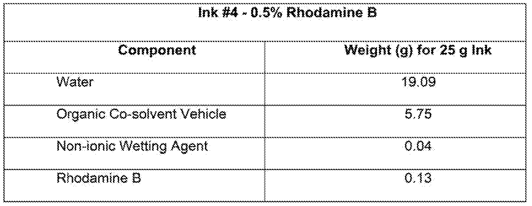
- the photoiumineseeni inks used had formulations as follows:
- the inks were jetted onto a bed of nylon (PA12) particles (Vesiosint® x1558, available from Evonik).
- the nylon particles had an average particle size of approximately 50 ⁇ .
- the layer thickness was approximately 100 m.
- Each 3- dimensional printed part was printed with a subsurface particle layer having a security feature.
- the photolumineseent ink was printed into a security area to form the security feature using a contone level of 255, a print resolution of 1200 x 1200, and a drop weight of 9 ng to achieve a print density of about 1 mg solids/cubic centimeter (cc) for the rhodarriihe B inks and about 6 mg soSids/cc for the fluorescein inks.
- the fusing Ink was printed in both the security area and non-security areas of the subsurface particle layer using a contone level of 80, a resolution of 1200 x 1200, and a drop weight of 1 .5 ng to achieve a print densit of about 4 mg soiids cc.
- a single pass of each of the inks was performed for the photolumi nescent com posit ⁇ layer. After the single pass, a curing pass was performed.
- a surface particle layer was printed on top of the subsurface fused layer.
- the surface particle layer included a masking area or feaiure printed over the subsurface security feature, as well as non-masking areas.
- the non-masking areas of the surface particle layer were prepared i the same manner as the non-security areas of the subsurface particle layer.
- the masking area was printed by reducing the contone level of the fusing ink to 40, while using the same resolution and drop weight as in other areas. This was sufficient to decrease the print density in the masking area to about 2 mg solids/cc,
- the printer powder supply and powde bed were filled with the nylon particles.
- the supply temperature was set at 1 0 °C and the print bed temperature was set at 130 °C.
- a heater under the print bed was set at 150 °C.
- the print speed was set at 10 Inches per second (ips) and the cure speed was set at 7 ips. Curing was performed using two 300 W bulbs placed approximately 1 em away from the surface of the powder bed.
Landscapes
- Chemical & Material Sciences (AREA)
- Engineering & Computer Science (AREA)
- Materials Engineering (AREA)
- Manufacturing & Machinery (AREA)
- Physics & Mathematics (AREA)
- Mechanical Engineering (AREA)
- Optics & Photonics (AREA)
- Civil Engineering (AREA)
- Ceramic Engineering (AREA)
- Composite Materials (AREA)
- Structural Engineering (AREA)
- Inorganic Chemistry (AREA)
- Life Sciences & Earth Sciences (AREA)
- Wood Science & Technology (AREA)
- Organic Chemistry (AREA)
- Inks, Pencil-Leads, Or Crayons (AREA)
Abstract
Description

Claims
Priority Applications (8)
| Application Number | Priority Date | Filing Date | Title |
|---|---|---|---|
| KR1020187022093A KR102142253B1 (en) | 2016-04-28 | 2017-04-19 | 3-dimensional printing |
| BR112018015436-9A BR112018015436B1 (en) | 2016-04-28 | 2017-04-19 | THREE-DIMENSIONAL PRINTING METHOD OF A PRINTED PIECE AND THREE-DIMENSIONAL PRINTING MATERIAL SET |
| EP17790129.5A EP3448655B1 (en) | 2016-04-28 | 2017-04-19 | 3-dimensional printing method and 3-dimensional printing material set |
| CN201780009151.5A CN108883576B (en) | 2016-04-28 | 2017-04-19 | 3D printing |
| US16/073,238 US11241828B2 (en) | 2016-04-28 | 2017-04-19 | 3-dimensional printing |
| JP2018539997A JP6845864B2 (en) | 2016-04-28 | 2017-04-19 | 3D printing |
| US17/540,048 US12337532B2 (en) | 2016-04-28 | 2021-12-01 | 3-dimensional printing |
| US17/540,060 US20250100212A9 (en) | 2016-04-28 | 2021-12-01 | 3-dimensional printing |
Applications Claiming Priority (6)
| Application Number | Priority Date | Filing Date | Title |
|---|---|---|---|
| PCT/US2016/029838 WO2017188961A1 (en) | 2016-04-28 | 2016-04-28 | Photoluminescent material sets |
| USPCT/US2016/029838 | 2016-04-28 | ||
| USPCT/US2016/029857 | 2016-04-28 | ||
| PCT/US2016/029857 WO2017188963A1 (en) | 2016-04-28 | 2016-04-28 | 3-dimensional printed parts |
| PCT/US2016/044369 WO2018022051A1 (en) | 2016-07-28 | 2016-07-28 | Optically active material sets |
| USPCT/US2016/044369 | 2016-07-28 |
Related Child Applications (3)
| Application Number | Title | Priority Date | Filing Date |
|---|---|---|---|
| US16/073,238 A-371-Of-International US11241828B2 (en) | 2016-04-28 | 2017-04-19 | 3-dimensional printing |
| US17/540,048 Division US12337532B2 (en) | 2016-04-28 | 2021-12-01 | 3-dimensional printing |
| US17/540,060 Continuation US20250100212A9 (en) | 2016-04-28 | 2021-12-01 | 3-dimensional printing |
Publications (1)
| Publication Number | Publication Date |
|---|---|
| WO2017189306A1 true WO2017189306A1 (en) | 2017-11-02 |
Family
ID=60160008
Family Applications (1)
| Application Number | Title | Priority Date | Filing Date |
|---|---|---|---|
| PCT/US2017/028413 Ceased WO2017189306A1 (en) | 2016-04-28 | 2017-04-19 | 3-dimensional printing |
Country Status (7)
| Country | Link |
|---|---|
| US (3) | US11241828B2 (en) |
| EP (1) | EP3448655B1 (en) |
| JP (1) | JP6845864B2 (en) |
| KR (1) | KR102142253B1 (en) |
| CN (1) | CN108883576B (en) |
| BR (1) | BR112018015436B1 (en) |
| WO (1) | WO2017189306A1 (en) |
Cited By (15)
| Publication number | Priority date | Publication date | Assignee | Title |
|---|---|---|---|---|
| CN108016031A (en) * | 2017-11-27 | 2018-05-11 | 深圳华云科技实业有限公司 | A kind of nozzle regulation and control method, equipment and computer-readable recording medium |
| WO2019099029A1 (en) | 2017-11-17 | 2019-05-23 | Hewlett-Packard Development Company, L.P. | Three-dimensional printing |
| WO2019099030A1 (en) * | 2017-11-17 | 2019-05-23 | Hewlett-Packard Development Company, L.P. | Three-dimensional printing |
| WO2019103750A1 (en) * | 2017-11-27 | 2019-05-31 | Hewlett-Packard Development Company, L.P. | Selective deposit of a functional agent |
| WO2019147261A1 (en) * | 2018-01-26 | 2019-08-01 | Hewlett-Packard Development Company, L.P. | Three-dimensional printing |
| WO2019217642A1 (en) | 2018-05-11 | 2019-11-14 | Carbon, Inc. | Reactive particulate materials useful for additive manufacturing |
| WO2020081066A1 (en) * | 2018-10-16 | 2020-04-23 | Hewlett-Packard Development Company, L.P. | Three-dimensional printing |
| WO2020149840A1 (en) | 2019-01-16 | 2020-07-23 | Hewlett-Packard Development Company, L.P. | Three-dimensional printing |
| WO2021029870A1 (en) * | 2019-08-12 | 2021-02-18 | Hewlett-Packard Development Company, L.P. | Three-dimensional printing with high density nanoparticles |
| WO2021080563A1 (en) * | 2019-10-22 | 2021-04-29 | Hewlett-Packard Development Company, L.P. | Three-dimensional printing with phosphorescent pigments |
| WO2021118555A1 (en) * | 2019-12-11 | 2021-06-17 | Hewlett-Packard Development Company, L.P. | Three-dimensional printing |
| US11167482B2 (en) * | 2018-10-19 | 2021-11-09 | Hewlett-Packard Development Company, L.P. | Three-dimensional printing |
| US20220088856A1 (en) * | 2019-06-10 | 2022-03-24 | Hewlett-Packard Development Company, L.P. | Three-dimensional printing |
| US20220324164A1 (en) * | 2019-03-15 | 2022-10-13 | Hewlett-Packard Development Company, L.P. | Coloured objects in additive manufacturing |
| GB2628015A (en) * | 2023-08-03 | 2024-09-11 | Atomik Am Ltd | Apparatus and method |
Families Citing this family (19)
| Publication number | Priority date | Publication date | Assignee | Title |
|---|---|---|---|---|
| US11173664B2 (en) * | 2017-04-24 | 2021-11-16 | The Boeing Company | Nanostructures for process monitoring and feedback control |
| WO2019121277A1 (en) * | 2017-12-20 | 2019-06-27 | Covestro Deutschland Ag | Powder-based additive manufacturing process |
| PL3727861T3 (en) * | 2017-12-20 | 2022-01-31 | Covestro Deutschland Ag | Powder-based additive production method |
| US11426818B2 (en) | 2018-08-10 | 2022-08-30 | The Research Foundation for the State University | Additive manufacturing processes and additively manufactured products |
| WO2020223124A1 (en) * | 2019-04-30 | 2020-11-05 | Brigham Young University | Spatial control of material properties in additive manufacturing |
| CN110253785B (en) * | 2019-06-21 | 2022-03-01 | 珠海天威飞马打印耗材有限公司 | 3D printing molding material and printing method |
| US11940634B2 (en) * | 2019-09-03 | 2024-03-26 | National Research Council Of Canada | 3D printed antenna |
| US11801617B2 (en) * | 2019-09-09 | 2023-10-31 | Xerox Corporation | Optical absorbing thermoplastic polymer particles and methods of production and uses thereof |
| US11866581B2 (en) | 2019-09-09 | 2024-01-09 | Xerox Corporation | Particles comprising polyamides with in-backbone optical absorbers and related methods |
| US11859051B2 (en) | 2019-09-09 | 2024-01-02 | Xerox Corporation | Polyamides with in-backbone optical absorbers and related methods |
| KR102881894B1 (en) | 2019-09-11 | 2025-11-05 | 소에이 가가쿠 고교 가부시키가이샤 | Nanostructured ink compositions for inkjet printing |
| CN112322110A (en) * | 2020-11-18 | 2021-02-05 | 四川大学 | Near-infrared reflection composite material for inkjet 3D printing and preparation method thereof |
| US11787944B2 (en) | 2020-11-25 | 2023-10-17 | Xerox Corporation | Pigmented polymer particles and methods of production and uses thereof |
| US12589548B2 (en) | 2022-02-11 | 2026-03-31 | The Regents Of The University Of California | Printing of conducting polymers without toxic solvents |
| WO2023192589A1 (en) * | 2022-03-31 | 2023-10-05 | Evolve Additive Solutions, Inc. | Additive manufacturing materials and methods for forming polyamide parts |
| CN120916902A (en) * | 2023-03-10 | 2025-11-07 | 克瑞尼股份有限公司 | Concealed machine-readable micro-optical features embedded in a lens layer |
| WO2024243120A1 (en) * | 2023-05-19 | 2024-11-28 | Vadient Optics, Llc | Optimized additive manufacturing of optics |
| TWI910648B (en) * | 2023-05-26 | 2026-01-01 | 美商瓦迪恩光學有限責任公司 | Method of additive manufacture of application-specific inorganic optical elements |
| KR102787564B1 (en) * | 2023-07-21 | 2025-04-03 | 나노씨엠에스(주) | Ink composition comprising nano copper compound of high absorbing ability in near infrared ray area |
Citations (4)
| Publication number | Priority date | Publication date | Assignee | Title |
|---|---|---|---|---|
| US20090215209A1 (en) * | 2006-04-14 | 2009-08-27 | Anc Maria J | Methods of depositing material, methods of making a device, and systems and articles for use in depositing material |
| US20110217544A1 (en) * | 2008-08-21 | 2011-09-08 | Innova Dynamics, Inc. | Enhanced surfaces, coatings, and related methods |
| WO2015164234A1 (en) * | 2014-04-25 | 2015-10-29 | Carbon3D, Inc. | Continuous three dimensional fabrication from immiscible liquids |
| US20150343673A1 (en) * | 2014-06-02 | 2015-12-03 | Vadient Optics, LLC. | Method for manufacturing an optical element |
Family Cites Families (94)
| Publication number | Priority date | Publication date | Assignee | Title |
|---|---|---|---|---|
| JPH0742482B2 (en) * | 1990-08-10 | 1995-05-10 | 日本電信電話株式会社 | Light molding method |
| US5351151A (en) | 1993-02-01 | 1994-09-27 | Levy George S | Optical filter using microlens arrays |
| JPH08156393A (en) | 1994-11-30 | 1996-06-18 | Kobayashi Ori Name Kk | Printed matter having indentification force and production thereof |
| US7226966B2 (en) | 2001-08-03 | 2007-06-05 | Nanogram Corporation | Structures incorporating polymer-inorganic particle blends |
| US5993854A (en) * | 1997-09-17 | 1999-11-30 | Phyzz, Inc. | Exothermic effervescent composition for improved fragrance dispersion |
| TWI285671B (en) | 1998-10-13 | 2007-08-21 | Orion 21 A D Pty Ltd | Luminescent gel coats and moldable resins |
| US6363606B1 (en) * | 1998-10-16 | 2002-04-02 | Agere Systems Guardian Corp. | Process for forming integrated structures using three dimensional printing techniques |
| ES2251173T5 (en) | 1999-01-12 | 2009-04-01 | Phyzz, Inc. | EXERCISE EFFECTIVE COMPOSITION TO IMPROVE THE DIFFUSION OF FRAGRANCE. |
| JP2003504199A (en) | 1999-07-16 | 2003-02-04 | エコグロ リミテッド | Application of photoluminescent pigments |
| WO2001038061A1 (en) * | 1999-10-26 | 2001-05-31 | University Of Southern California | Process of making a three-dimensional object |
| US7297388B2 (en) | 2000-07-17 | 2007-11-20 | Ecoglo Limited | Photo-luminescent pigment application |
| ATE383939T1 (en) | 2002-09-21 | 2008-02-15 | Evonik Degussa Gmbh | METHOD FOR PRODUCING A THREE-DIMENSIONAL OBJECT |
| GB0300529D0 (en) | 2003-01-10 | 2003-02-12 | Qinetiq Nanomaterials Ltd | Improvements in and relating to ink jet deposition |
| WO2005021247A1 (en) | 2003-08-28 | 2005-03-10 | Fuji Photo Film Co., Ltd. | Process for producing three-dimensional shaped article |
| JP4034691B2 (en) | 2003-05-09 | 2008-01-16 | ミネベア株式会社 | Rotation angle sensor |
| CA2526100A1 (en) * | 2003-05-21 | 2004-12-29 | Z Corporation | Thermoplastic powder material system for appearance models from 3d printing systems |
| US7091271B2 (en) | 2003-08-18 | 2006-08-15 | Eastman Kodak Company | Core shell nanocomposite optical plastic article |
| FR2859128B1 (en) | 2003-08-29 | 2006-03-10 | Centre Nat Rech Scient | METHOD AND DEVICE FOR MANUFACTURING A THREE DIMENSIONAL MULTIMATERIAL COMPONENT BY INKJET TYPE PRINTING |
| US20050072113A1 (en) | 2003-10-03 | 2005-04-07 | Collins David C. | Uses of support material in solid freeform fabrication systems |
| US7365129B2 (en) * | 2003-10-14 | 2008-04-29 | Hewlett-Packard Development Company, L.P. | Polymer systems with reactive and fusible properties for solid freeform fabrication |
| EP1687664B1 (en) | 2003-11-14 | 2016-06-29 | Eric Baer | Multilayer polymer gradient index (grin) lenses |
| JP2005254534A (en) * | 2004-03-10 | 2005-09-22 | Fuji Photo Film Co Ltd | Manufacturing method of three-dimensional structure |
| DE102004012682A1 (en) * | 2004-03-16 | 2005-10-06 | Degussa Ag | Process for the production of three-dimensional objects by means of laser technology and application of an absorber by inkjet method |
| DE102004020452A1 (en) | 2004-04-27 | 2005-12-01 | Degussa Ag | Method for producing three-dimensional objects by means of electromagnetic radiation and applying an absorber by inkjet method |
| US7713590B2 (en) | 2004-09-02 | 2010-05-11 | Ara Safety, Inc. | Photoluminescent coating formulation, method of application, and coated articles |
| US7285501B2 (en) | 2004-09-17 | 2007-10-23 | Hewlett-Packard Development Company, L.P. | Method of forming a solution processed device |
| CN101102905B (en) | 2005-01-14 | 2011-01-12 | 卡伯特公司 | Security feature, use thereof and method of manufacture |
| JP5023506B2 (en) * | 2005-02-28 | 2012-09-12 | Dic株式会社 | Method for producing conductive paint |
| JP2006274077A (en) | 2005-03-29 | 2006-10-12 | Fuji Photo Film Co Ltd | Inkjet ink composition, and image-forming method and recorded matter obtained using the same |
| US20070241482A1 (en) | 2006-04-06 | 2007-10-18 | Z Corporation | Production of three-dimensional objects by use of electromagnetic radiation |
| DE102006047852A1 (en) | 2006-10-10 | 2008-04-17 | Giesecke & Devrient Gmbh | Authenticity feature in the form of a luminescent substance |
| WO2008067496A2 (en) | 2006-11-29 | 2008-06-05 | Desktop Factory Inc. | Sinterable powder |
| WO2008077850A2 (en) * | 2006-12-21 | 2008-07-03 | Agfa Graphics Nv | 3d-inkjet printing methods |
| US20080149164A1 (en) | 2006-12-22 | 2008-06-26 | General Electric Company | Luminescent thermoplastic compositions and articles with enhanced edge emission |
| US7972426B2 (en) | 2007-05-09 | 2011-07-05 | Hewlett-Packard Development Company, L.P. | Printed security mark |
| JP2009006538A (en) * | 2007-06-27 | 2009-01-15 | Seiko Epson Corp | 3D modeling apparatus and 3D modeling method |
| US7919018B2 (en) | 2007-10-30 | 2011-04-05 | Voxtel, Inc. | Photoactive taggant materials comprising semiconductor nanoparticles and lanthanide ions |
| GB2457949B (en) | 2008-02-29 | 2010-05-12 | Rue De Int Ltd | Security documents |
| CN101556345A (en) * | 2008-04-09 | 2009-10-14 | 鸿富锦精密工业(深圳)有限公司 | Manufacturing method of micro lens |
| WO2009139395A1 (en) | 2008-05-15 | 2009-11-19 | 富士フイルム株式会社 | Process for producing three-dimensional shaped object, material for three-dimensional shaping, and three-dimensional shaped object |
| JP2010001425A (en) | 2008-06-23 | 2010-01-07 | Toppan Printing Co Ltd | Fluorescent ink and fluorescent printed matter |
| DE102008058177A1 (en) | 2008-11-20 | 2010-06-24 | Eos Gmbh Electro Optical Systems | Method for identifying laser sintering powders |
| EP2449696B1 (en) * | 2009-06-30 | 2019-10-09 | LG Electronics Inc. | Method for prioritizing operation of relay node in a wireless communication system and apparatus for the same |
| JP2011129787A (en) | 2009-12-18 | 2011-06-30 | Seiko Epson Corp | Conductor pattern forming ink, conductor pattern, wiring board |
| CN101819647A (en) | 2010-05-08 | 2010-09-01 | 福建鸿博印刷股份有限公司 | Anti-counterfeiting printing method by using invisible two-dimensional codes |
| JP5724317B2 (en) | 2010-11-18 | 2015-05-27 | ソニー株式会社 | 3D modeling equipment |
| US20120202022A1 (en) | 2011-02-08 | 2012-08-09 | Detlef Schulze-Hagenest | Printed product with authentication bi-fluorescence feature |
| US9281186B2 (en) | 2011-03-31 | 2016-03-08 | Ats Automation Tooling Systems Inc. | Colored photovoltaic modules and methods of construction |
| SE536670C2 (en) * | 2011-08-26 | 2014-05-13 | Digital Metal Ab | Layer-based manufacture of free-form micro-components of multimaterial |
| EP2896495B1 (en) | 2012-09-13 | 2017-12-20 | Fuji Machine Mfg. Co., Ltd. | Electronic device manufacturing apparatus |
| DE102012220701A1 (en) | 2012-11-13 | 2014-05-15 | Bundesdruckerei Gmbh | Security feature for a value and / or security product, the security and / or security product and method for producing the security feature |
| EP2952360A4 (en) | 2013-02-01 | 2016-11-09 | Yu-Chen Hwang | Printing decorative film having stereo effect and decorative plastic product thereof |
| US20140263674A1 (en) | 2013-03-15 | 2014-09-18 | Conformis, Inc. | Systems, Methods, and Apparatus for Integrating Scannable Codes in Medical Devices |
| US10358569B2 (en) | 2013-03-15 | 2019-07-23 | South Dakota Board Of Regents | Systems and methods for printing patterns using near infrared upconverting inks |
| US20140263667A1 (en) | 2013-03-15 | 2014-09-18 | Leon Mege Inc. | Articles displaying two dimensional barcodes |
| EP2969482B1 (en) | 2013-03-15 | 2018-05-09 | 3D Systems, Inc. | Three dimensional printing material system |
| US20160054474A1 (en) | 2013-05-02 | 2016-02-25 | Vadient Optics LLC. | Gradient refractive index optics with low dispersion using nanoparticles |
| US20160167299A1 (en) * | 2013-07-31 | 2016-06-16 | Essilor International(Compagnie Generale D'optique) | Additive manufacturing for transparent ophthalmic lens |
| CN115723335A (en) | 2013-10-17 | 2023-03-03 | Xjet有限公司 | Support ink for three-dimensional (3D) printing |
| FR3012366B1 (en) | 2013-10-28 | 2019-05-24 | Idemia France | METHOD FOR MANUFACTURING AN IDENTITY DOCUMENT |
| JP2015112836A (en) | 2013-12-13 | 2015-06-22 | コニカミノルタ株式会社 | Apparatus for molding three-dimensional object, and method for molding three-dimensional object |
| US10886613B2 (en) * | 2013-12-31 | 2021-01-05 | 3M Innovative Properties Company | Volume based gradient index lens by additive manufacturing |
| CN103755889A (en) | 2014-01-10 | 2014-04-30 | 上海那恒新材料有限公司 | Light-emitting high precision three-dimensionally moulded photosensitive resin composition |
| US10544311B2 (en) | 2014-01-16 | 2020-01-28 | Hewlett-Packard Development Company, L.P. | Polymeric powder composition for three-dimensional (3D) printing |
| EP3094469B1 (en) * | 2014-01-16 | 2019-11-13 | Hewlett-Packard Development Company, L.P. | Generating a three-dimensional object |
| US9400910B2 (en) | 2014-02-18 | 2016-07-26 | Adobe Systems Incorporated | Method and apparatus for storing and retrieving data embedded into the surface of a 3D printed object |
| WO2015138567A1 (en) | 2014-03-11 | 2015-09-17 | 3D Systems, Incorporated | 3d printing colorization |
| JP2015171781A (en) | 2014-03-12 | 2015-10-01 | セイコーエプソン株式会社 | Method for manufacturing three-dimensional molded article, apparatus for manufacturing three-dimensional molded article, and three-dimensional molded article |
| JP2015174426A (en) | 2014-03-18 | 2015-10-05 | セイコーエプソン株式会社 | Three-dimensional structure manufacturing method, three-dimensional structure manufacturing apparatus, and three-dimensional structure |
| US9816058B2 (en) | 2014-04-10 | 2017-11-14 | 3D Systems, Inc. | Three-dimensional soap objects formed by additive manufacturing |
| CN103991217B (en) | 2014-04-30 | 2017-03-15 | 中国科学院化学研究所 | A kind of 3D printing molding method |
| US10434708B2 (en) * | 2014-04-30 | 2019-10-08 | Hewlett-Packard Development Company, L.P. | Three-dimensional (3D) printing method |
| JP2015221526A (en) * | 2014-05-23 | 2015-12-10 | コニカミノルタ株式会社 | Method of producing three-dimensional molded object, three-dimensional molding apparatus, program and three-dimensional molded object |
| US9855737B2 (en) | 2014-09-08 | 2018-01-02 | Vadient Optics, Llc | Nanocomposite-ink factory |
| US9644107B2 (en) | 2014-06-02 | 2017-05-09 | Vadient Optics, LLC. | Achromatic optical-dispersion corrected gradient refractive index optical-element |
| US9313360B2 (en) | 2014-07-30 | 2016-04-12 | Hewlett-Packard Development Company, L.P. | Encoding data in an image |
| CN204036857U (en) | 2014-08-19 | 2014-12-24 | 珠海天威飞马打印耗材有限公司 | Possesses the three-dimensional printer of moulding material measuring ability |
| CN104149350A (en) | 2014-08-19 | 2014-11-19 | 珠海天威飞马打印耗材有限公司 | Three-dimensional printer with formed material detection function and printing method thereof |
| EP3197669B1 (en) * | 2014-09-26 | 2020-04-01 | Hewlett-Packard Development Company, L.P. | 3-dimensional printing |
| WO2016048380A1 (en) | 2014-09-26 | 2016-03-31 | Hewlett-Packard Development Company, L.P. | 3-dimensional printing |
| WO2016053248A1 (en) | 2014-09-29 | 2016-04-07 | Hewlett-Packard Development Company, L.P. | Coalescing agent for three-dimensional (3d) printing |
| US10392521B2 (en) * | 2014-09-30 | 2019-08-27 | Hewlett-Packard Development Company, L.P. | Particle compositions for three-dimensional printing |
| KR102444204B1 (en) | 2015-02-10 | 2022-09-19 | 옵토멕 인코포레이티드 | Method for manufacturing three-dimensional structures by in-flight curing of aerosols |
| JP6618688B2 (en) * | 2015-03-03 | 2019-12-11 | セイコーエプソン株式会社 | Three-dimensional modeling apparatus, manufacturing method, and computer program |
| BR112017015945B1 (en) | 2015-04-30 | 2021-12-28 | Hewlett-Packard Development Company, L.P. | THREE-DIMENSIONAL PRINTING METHOD, SYSTEM FOR THREE-DIMENSIONAL PRINTING AND NON-TRANSITORY MACHINE-READABLE STORAGE MEDIA |
| JP6668649B2 (en) | 2015-09-17 | 2020-03-18 | 株式会社リコー | 3D modeling equipment, programs |
| US20170145155A1 (en) | 2015-11-19 | 2017-05-25 | Eastman Chemical Company | Compositions for the production of objects using additive manufacturing |
| CN105346089A (en) | 2015-12-02 | 2016-02-24 | 上海理工大学 | Method for making variable refractive index optical waveguide based on 3D printing |
| AU2017230818A1 (en) | 2016-03-10 | 2018-09-20 | San Draw Inc. | Apparatuses, systems and methods for generating three-dimensional objects with adjustable properties |
| CN108496055B (en) * | 2016-04-15 | 2020-10-27 | 惠普发展公司,有限责任合伙企业 | 3D printed load cell components |
| EP3448943A4 (en) | 2016-04-28 | 2019-12-25 | Hewlett-Packard Development Company, L.P. | SETS OF PHOTOLUMINESCENT MATERIALS |
| US11465341B2 (en) * | 2016-04-28 | 2022-10-11 | Hewlett-Packard Development Company, L.P. | 3-dimensional printed parts |
| CN109070465A (en) | 2016-07-28 | 2018-12-21 | 惠普发展公司,有限责任合伙企业 | Optically active material suit |
| JP1666234S (en) * | 2019-11-20 | 2020-08-17 |
-
2017
- 2017-04-19 BR BR112018015436-9A patent/BR112018015436B1/en active IP Right Grant
- 2017-04-19 CN CN201780009151.5A patent/CN108883576B/en active Active
- 2017-04-19 JP JP2018539997A patent/JP6845864B2/en active Active
- 2017-04-19 KR KR1020187022093A patent/KR102142253B1/en active Active
- 2017-04-19 EP EP17790129.5A patent/EP3448655B1/en active Active
- 2017-04-19 WO PCT/US2017/028413 patent/WO2017189306A1/en not_active Ceased
- 2017-04-19 US US16/073,238 patent/US11241828B2/en active Active
-
2021
- 2021-12-01 US US17/540,048 patent/US12337532B2/en active Active
- 2021-12-01 US US17/540,060 patent/US20250100212A9/en not_active Abandoned
Patent Citations (4)
| Publication number | Priority date | Publication date | Assignee | Title |
|---|---|---|---|---|
| US20090215209A1 (en) * | 2006-04-14 | 2009-08-27 | Anc Maria J | Methods of depositing material, methods of making a device, and systems and articles for use in depositing material |
| US20110217544A1 (en) * | 2008-08-21 | 2011-09-08 | Innova Dynamics, Inc. | Enhanced surfaces, coatings, and related methods |
| WO2015164234A1 (en) * | 2014-04-25 | 2015-10-29 | Carbon3D, Inc. | Continuous three dimensional fabrication from immiscible liquids |
| US20150343673A1 (en) * | 2014-06-02 | 2015-12-03 | Vadient Optics, LLC. | Method for manufacturing an optical element |
Non-Patent Citations (1)
| Title |
|---|
| See also references of EP3448655A4 * |
Cited By (35)
| Publication number | Priority date | Publication date | Assignee | Title |
|---|---|---|---|---|
| CN111433003A (en) * | 2017-11-17 | 2020-07-17 | 惠普发展公司,有限责任合伙企业 | Three-dimensional printing |
| WO2019099029A1 (en) | 2017-11-17 | 2019-05-23 | Hewlett-Packard Development Company, L.P. | Three-dimensional printing |
| WO2019099030A1 (en) * | 2017-11-17 | 2019-05-23 | Hewlett-Packard Development Company, L.P. | Three-dimensional printing |
| US11738508B2 (en) | 2017-11-17 | 2023-08-29 | Hewlett-Packard Development Company, L.P. | Three-dimensional printing |
| US11292189B2 (en) | 2017-11-17 | 2022-04-05 | Hewlett-Packard Development Company, L.P. | Three-dimensional printing |
| EP3687769A4 (en) * | 2017-11-17 | 2021-06-16 | Hewlett-Packard Development Company, L.P. | THREE-DIMENSIONAL PRINTING |
| CN111344137A (en) * | 2017-11-27 | 2020-06-26 | 惠普发展公司,有限责任合伙企业 | Selective deposition of functional agents |
| CN108016031A (en) * | 2017-11-27 | 2018-05-11 | 深圳华云科技实业有限公司 | A kind of nozzle regulation and control method, equipment and computer-readable recording medium |
| US12042987B2 (en) | 2017-11-27 | 2024-07-23 | Hewlett-Packard Development Company, L.P. | Selective deposit of a functional agent |
| WO2019103750A1 (en) * | 2017-11-27 | 2019-05-31 | Hewlett-Packard Development Company, L.P. | Selective deposit of a functional agent |
| US11384241B2 (en) | 2018-01-26 | 2022-07-12 | Hewlett-Packard Development Company, L.P. | Three-dimensional printing |
| WO2019147261A1 (en) * | 2018-01-26 | 2019-08-01 | Hewlett-Packard Development Company, L.P. | Three-dimensional printing |
| WO2019217642A1 (en) | 2018-05-11 | 2019-11-14 | Carbon, Inc. | Reactive particulate materials useful for additive manufacturing |
| US11390705B2 (en) | 2018-05-11 | 2022-07-19 | Carbon, Inc. | Reactive particulate materials useful for additive manufacturing |
| WO2019217641A1 (en) | 2018-05-11 | 2019-11-14 | Carbon, Inc. | Sustainable chemistry systems for recyclable dental models and other additively manufactured products |
| US11299576B2 (en) | 2018-05-11 | 2022-04-12 | Carbon, Inc. | Sustainable chemistry systems for recyclable dental models and other additively manufactured products |
| US11712845B2 (en) | 2018-10-16 | 2023-08-01 | Hewlett-Packard Development Company, L.P. | Three-dimensional printing |
| WO2020081066A1 (en) * | 2018-10-16 | 2020-04-23 | Hewlett-Packard Development Company, L.P. | Three-dimensional printing |
| US12214549B2 (en) | 2018-10-16 | 2025-02-04 | Hewlett-Packard Development Company, L.P. | Three-dimensional printing |
| US11167482B2 (en) * | 2018-10-19 | 2021-11-09 | Hewlett-Packard Development Company, L.P. | Three-dimensional printing |
| EP3883750A4 (en) * | 2019-01-16 | 2022-06-29 | Hewlett-Packard Development Company, L.P. | Three-dimensional printing |
| US11958982B2 (en) | 2019-01-16 | 2024-04-16 | Hewlett-Packard Development Company, L.P. | Three-dimensional printing |
| WO2020149840A1 (en) | 2019-01-16 | 2020-07-23 | Hewlett-Packard Development Company, L.P. | Three-dimensional printing |
| US20220324164A1 (en) * | 2019-03-15 | 2022-10-13 | Hewlett-Packard Development Company, L.P. | Coloured objects in additive manufacturing |
| US12358229B2 (en) * | 2019-03-15 | 2025-07-15 | Peridot Print Llc | Coloured objects in additive manufacturing |
| US20220088856A1 (en) * | 2019-06-10 | 2022-03-24 | Hewlett-Packard Development Company, L.P. | Three-dimensional printing |
| US12115723B2 (en) * | 2019-06-10 | 2024-10-15 | Hewlett-Packard Development Company, L.P. | Three-dimensional printing |
| WO2021029870A1 (en) * | 2019-08-12 | 2021-02-18 | Hewlett-Packard Development Company, L.P. | Three-dimensional printing with high density nanoparticles |
| US12377604B2 (en) | 2019-08-12 | 2025-08-05 | Peridot Print Llc | Three-dimensional printing with high density nanoparticles |
| WO2021080563A1 (en) * | 2019-10-22 | 2021-04-29 | Hewlett-Packard Development Company, L.P. | Three-dimensional printing with phosphorescent pigments |
| US11752692B2 (en) | 2019-10-22 | 2023-09-12 | Hewlett-Packard Development Company, L.P. | Three-dimensional printing with phosphorescent pigments |
| WO2021118555A1 (en) * | 2019-12-11 | 2021-06-17 | Hewlett-Packard Development Company, L.P. | Three-dimensional printing |
| US12145315B2 (en) | 2019-12-11 | 2024-11-19 | Hewlett-Packard Development Company, L.P. | Three-dimensional printing |
| GB2628015B (en) * | 2023-08-03 | 2025-04-23 | Atomik Am Ltd | Apparatus and method |
| GB2628015A (en) * | 2023-08-03 | 2024-09-11 | Atomik Am Ltd | Apparatus and method |
Also Published As
| Publication number | Publication date |
|---|---|
| KR102142253B1 (en) | 2020-08-07 |
| JP6845864B2 (en) | 2021-03-24 |
| CN108883576B (en) | 2021-08-20 |
| JP2019507691A (en) | 2019-03-22 |
| US20250100212A9 (en) | 2025-03-27 |
| US20220088860A1 (en) | 2022-03-24 |
| EP3448655A4 (en) | 2019-12-11 |
| BR112018015436A2 (en) | 2018-12-18 |
| US20190039294A1 (en) | 2019-02-07 |
| US12337532B2 (en) | 2025-06-24 |
| US20220088859A1 (en) | 2022-03-24 |
| KR20180099847A (en) | 2018-09-05 |
| EP3448655A1 (en) | 2019-03-06 |
| EP3448655B1 (en) | 2021-09-01 |
| CN108883576A (en) | 2018-11-23 |
| BR112018015436B1 (en) | 2022-11-29 |
| US11241828B2 (en) | 2022-02-08 |
Similar Documents
| Publication | Publication Date | Title |
|---|---|---|
| US12337532B2 (en) | 3-dimensional printing | |
| US11427725B2 (en) | Photoluminescent material sets | |
| US11981075B2 (en) | 3-dimensional printed parts | |
| US11104816B2 (en) | 3-dimensional printing | |
| CN108883574B (en) | material set | |
| EP3448941B1 (en) | Material sets | |
| US20180104894A1 (en) | Three-dimensional printing | |
| US11679553B2 (en) | Compositions for printing | |
| US20230211549A1 (en) | Build compositions | |
| WO2017176251A1 (en) | Photosensitive material sets |
Legal Events
| Date | Code | Title | Description |
|---|---|---|---|
| ENP | Entry into the national phase |
Ref document number: 20187022093 Country of ref document: KR Kind code of ref document: A Ref document number: 2018539997 Country of ref document: JP Kind code of ref document: A |
|
| REG | Reference to national code |
Ref country code: BR Ref legal event code: B01A Ref document number: 112018015436 Country of ref document: BR |
|
| NENP | Non-entry into the national phase |
Ref country code: DE |
|
| 121 | Ep: the epo has been informed by wipo that ep was designated in this application |
Ref document number: 17790129 Country of ref document: EP Kind code of ref document: A1 |
|
| WWE | Wipo information: entry into national phase |
Ref document number: 2017790129 Country of ref document: EP |
|
| ENP | Entry into the national phase |
Ref document number: 2017790129 Country of ref document: EP Effective date: 20181128 |
|
| ENP | Entry into the national phase |
Ref document number: 112018015436 Country of ref document: BR Kind code of ref document: A2 Effective date: 20180727 |