WO2017191837A1 - 加速空洞、加速器及び加速空洞の共振周波数調整方法 - Google Patents
加速空洞、加速器及び加速空洞の共振周波数調整方法 Download PDFInfo
- Publication number
- WO2017191837A1 WO2017191837A1 PCT/JP2017/017207 JP2017017207W WO2017191837A1 WO 2017191837 A1 WO2017191837 A1 WO 2017191837A1 JP 2017017207 W JP2017017207 W JP 2017017207W WO 2017191837 A1 WO2017191837 A1 WO 2017191837A1
- Authority
- WO
- WIPO (PCT)
- Prior art keywords
- surface portion
- deformation
- acceleration cavity
- adjusting
- resonance frequency
- Prior art date
- Legal status (The legal status is an assumption and is not a legal conclusion. Google has not performed a legal analysis and makes no representation as to the accuracy of the status listed.)
- Ceased
Links
Images


Classifications
-
- H—ELECTRICITY
- H05—ELECTRIC TECHNIQUES NOT OTHERWISE PROVIDED FOR
- H05H—PLASMA TECHNIQUE; PRODUCTION OF ACCELERATED ELECTRICALLY-CHARGED PARTICLES OR OF NEUTRONS; PRODUCTION OR ACCELERATION OF NEUTRAL MOLECULAR OR ATOMIC BEAMS
- H05H7/00—Details of devices of the types covered by groups H05H9/00, H05H11/00, H05H13/00
- H05H7/14—Vacuum chambers
- H05H7/18—Cavities; Resonators
- H05H7/20—Cavities; Resonators with superconductive walls
-
- H—ELECTRICITY
- H05—ELECTRIC TECHNIQUES NOT OTHERWISE PROVIDED FOR
- H05H—PLASMA TECHNIQUE; PRODUCTION OF ACCELERATED ELECTRICALLY-CHARGED PARTICLES OR OF NEUTRONS; PRODUCTION OR ACCELERATION OF NEUTRAL MOLECULAR OR ATOMIC BEAMS
- H05H7/00—Details of devices of the types covered by groups H05H9/00, H05H11/00, H05H13/00
- H05H7/22—Details of linear accelerators, e.g. drift tubes
-
- H—ELECTRICITY
- H05—ELECTRIC TECHNIQUES NOT OTHERWISE PROVIDED FOR
- H05H—PLASMA TECHNIQUE; PRODUCTION OF ACCELERATED ELECTRICALLY-CHARGED PARTICLES OR OF NEUTRONS; PRODUCTION OR ACCELERATION OF NEUTRAL MOLECULAR OR ATOMIC BEAMS
- H05H9/00—Linear accelerators
-
- H—ELECTRICITY
- H05—ELECTRIC TECHNIQUES NOT OTHERWISE PROVIDED FOR
- H05H—PLASMA TECHNIQUE; PRODUCTION OF ACCELERATED ELECTRICALLY-CHARGED PARTICLES OR OF NEUTRONS; PRODUCTION OR ACCELERATION OF NEUTRAL MOLECULAR OR ATOMIC BEAMS
- H05H9/00—Linear accelerators
- H05H9/02—Travelling-wave linear accelerators
Definitions
- the present invention relates to an acceleration cavity, an accelerator, and a resonance frequency adjusting method for the acceleration cavity.
- a superconducting linear accelerator that accelerates protons or heavy particles (heavy ions)
- acceleration is performed using a quarter wave resonator (QWR) or a half wave resonator (HWR).
- QWR quarter wave resonator
- HWR half wave resonator
- a cavity may be formed.
- Microwaves are injected into the acceleration cavity to generate an accelerating electric field that accelerates protons or heavy particles.
- the particles can be efficiently accelerated by synchronizing the inherent resonance frequency of the acceleration cavity with the frequency of the accelerating electric field. Therefore, it is necessary to tune the acceleration cavity in order to adjust the resonance frequency of the acceleration cavity.
- Patent Documents 1 and 2 below disclose inventions related to tuning of an acceleration cavity.
- Acceleration cavity tuning may be performed before the accelerator is operated or may be performed during the operation.
- Tuning performed before operation includes adjusting the length of some of the components incorporated into the cavity, plastically deforming the cavity itself, and changing the cavity shape, and And polishing the inner surface of the cavity. Pre-tuning before operation is adjusted in a range where the resonance frequency is large.
- Tune performed during operation includes reversibly adjusting the cavity shape by elastically deforming the cavity itself, and inserting parts inside the cavity. Tuning during operation is performed in order to restore the resonance frequency that slightly changes depending on the operation conditions.
- the tuning is performed by deforming the acceleration cavity
- a method is employed in which the acceleration cavity is deformed in a concave shape in the beam axis direction and inside the acceleration cavity.
- the ratio of the acceleration cavities to the total length of the accelerator is increased, and the entire accelerator can be made compact.
- the 1/4 wavelength type resonator or the 1/2 wavelength type resonator has a structure having high rigidity
- a tuner having a function of deforming the resonator has a large-scale configuration capable of applying a high deformation force. There is a need to.
- the tuner has, for example, a structure in which a vertically long cylindrical resonator is sandwiched from an outer peripheral surface. At this time, the pressing force applied by the tuner is in the unit of several tens of kN. Therefore, when a tuner is arranged between the acceleration cavities, it is necessary to secure a certain space.
- An object of the present invention is to provide an acceleration cavity, an accelerator, and a method for adjusting the resonance frequency of an acceleration cavity that can change the inherent resonance frequency of the acceleration cavity.
- the acceleration cavity according to the first aspect of the present invention is a plate-like member that is disposed in parallel with the vertical direction in the axial direction, and has a body part having a cylindrical shape on the side surface part and an upper part of the body part. An upper surface portion; and a deformation adjusting portion that applies a pressing force to the upper surface portion and deforms the upper surface portion.
- the body portion having the cylindrical shape on the side surface portion is arranged with the axial direction parallel to the vertical direction, and the upper surface portion which is a plate-like member is provided on the upper portion of the body portion.
- the deformation adjusting unit applies a pressing force to the upper surface portion to deform the upper surface portion.
- a plurality of the deformation adjustment units may be provided, and each of the deformation adjustment units may apply a pressing force to a different position of the upper surface part.
- each of the plurality of deformation adjustment units is provided at intervals along the circumferential direction of the upper surface portion.
- a rib projecting upward may be provided on the surface of the upper surface portion, and the deformation adjusting portion may apply a pressing force in contact with the rib.
- the deformation adjusting unit is in contact with the rib provided on the upper surface, and the upper surface is deformed by applying a pressing force to the rib. At this time, since the pressing force is widely transmitted in the plane of the upper surface portion via the rib, the deformed portion can be increased along the longitudinal direction of the rib.
- the upper surface portion may be thinner than other portions in the thickness of the portion where the deformation adjusting portion contacts.
- the plate thickness of the portion to which the pressing force is applied when the deformation adjusting portion comes into contact is thinner than the other portions, so that the upper surface portion can be deformed with a small pressing force.
- the upper surface portion may be formed in a flat shape at a portion where the deformation adjusting portion contacts.
- the portion to which the pressing force is applied by contact with the deformation adjusting portion is formed in a flat shape with a straight section, so that the cross section is formed with a curved surface such as an arc shape.
- the upper surface portion can be deformed with a small pressing force.
- the accelerator according to the second aspect of the present invention includes the acceleration cavity of the first aspect.
- the method for adjusting the resonant frequency of the accelerating cavity according to the third aspect of the present invention is provided at the upper part of the body part, the body part having an axial direction arranged parallel to the vertical direction and having a cylindrical side surface part, A method for adjusting a resonance frequency of an accelerating cavity including an upper surface portion that is a plate-shaped member, wherein the deformation adjusting portion includes a step of applying a pressing force to the upper surface portion to deform the upper surface portion.
- the upper surface portion is plastically deformed or elastically deformed.
- the upper surface portion is deformed by all or some of the deformation adjustment portions.
- the deformation adjusting portion since the upper surface portion provided on the upper portion of the body portion of the acceleration cavity is deformed, the deformation adjusting portion does not occupy the space between the adjacent acceleration cavities, and the acceleration cavity is It is possible to change the inherent resonance frequency.
- 1 is a perspective view showing a quarter wavelength resonator according to a first embodiment of the present invention.
- 1 is a longitudinal sectional view showing a quarter wavelength resonator and a container according to a first embodiment of the present invention. It is a perspective view which shows the upper part of the quarter wavelength resonator which concerns on 1st Embodiment of this invention. It is a longitudinal cross-sectional view which shows the deformation
- 1 is a plan view showing a quarter wavelength resonator according to a first embodiment of the present invention. It is an end view which shows the upper part of the quarter wavelength resonator which concerns on 1st Embodiment of this invention, The shape after a deformation
- the superconducting linear accelerator according to the present embodiment accelerates protons or heavy particles (heavy ions).
- an acceleration cavity is formed using a quarter wave resonator (QWR: Quarter Wave Resonator) 1.
- QWR Quarter Wave Resonator
- the quarter wavelength resonator 1 may be used as a single unit or may be used as a plurality of units connected in series.
- Microwaves are input to the quarter wavelength resonator 1, and an accelerating electric field that accelerates protons or heavy particles is generated in the quarter wavelength resonator 1.
- the quarter-wave resonator 1 has been described with reference to the drawings. However, the present invention also applies to a half-wave resonator (HWR: Half Wave Resonator) used in a superconducting linear accelerator. Applicable.
- HWR Half Wave Resonator
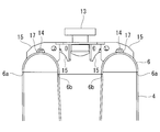
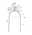
- the quarter-wavelength resonator 1 is made of niobium and includes a body portion 2 having a cylindrical side surface, a center conductor 3 provided inside the body portion 2, and the like.
- the body portion 2 has a side surface portion 4 whose outer peripheral surface is cylindrical, and a lower surface portion 5 and an upper surface portion 6 connected to the side surface portion 4.
- the side surface portion 4, the lower surface portion 5 and the upper surface portion 6 are constituted by plate-like members having a plate thickness of 3 mm to 4 mm, for example.
- the interior of the body part 2 is a space closed by the side surface part 4, the lower surface part 5 and the upper surface part 6 of the body part 2 and the central conductor 3.
- the lower surface portion 5 has a circular shape in plan view, and is, for example, a bowl shape or a flat plate shape.
- the upper surface portion 6 has an annular shape in plan view, and the longitudinal section has a curved surface that is convex upward. Note that the upper surface portion 6 may have a flat surface portion as well as a curved surface.
- the outer peripheral edge 6 a of the upper surface portion 6 is connected to the upper portion of the side surface portion 4, and the inner peripheral edge 6 b of the upper surface portion 6 is connected to the upper portion of the center conductor 3.
- a pair of beam ports 7 in which openings 8 through which protons or heavy particles pass are formed in the lower portion of the body portion 2.
- Each beam port 7 has a flange 9 formed at the end thereof, and can be connected to the beam port 7 of another quarter wavelength resonator through a connecting component (not shown).
- the beam port 7 protrudes from the side surface portion 4 of the body portion 2 and is provided in a direction perpendicular to the axial direction of the body portion 2.
- the two beam ports 7 are provided on the same axis, and the opening 8 formed inside is also arranged on the same axis.
- the center conductor 3 has a tapered connecting portion 10 and an annular beam passing portion 11 having an opening 12 inside.
- the connecting portion 10 has a tapered shape with a large upper diameter and a small lower diameter.
- the lower part of the connection part 10 and the upper part of the beam passage part 11 are connected continuously, and one continuous space is formed inside the connection part 10 and the inside of the beam passage part 11, and the accelerator is operated. In, for example, liquid helium is filled.
- the connecting portion 10 may have a cylindrical shape having the same upper diameter and lower diameter.
- the beam passage portion 11 has a shape in which two bowl-shaped members are combined, and has a curved surface that is convex toward the beam port 7 side.
- a cylindrical opening 12 is formed at the center of the beam passage 11, and both ends of the opening 12 are connected to the surface of the beam passage 11 on the beam port 7 side.
- the opening 12 of the beam passage portion 11 is provided coaxially with the opening 8 of the beam port 7. Protons or heavy particles pass through the opening 12 of the beam passage 11.
- the thickness of the beam passage portion 11 in the beam axis direction and the length of the opening portion 12 in the beam axis direction are longer than the diameter of the lowermost end of the connection portion 10, and the connection portion between the connection portion 10 and the beam passage portion 11 is bent. It has a shape.
- the shape of the connection part of the connection part 10 and the beam passage part 11 is not limited to when it has a bending shape.
- the thickness of the beam passage portion 11 in the beam axis direction and the length of the opening portion 12 in the beam axis direction are the same as the diameter of the cylindrical connection portion 10.
- the beam passing portion 11 is not limited to an annular shape, but has a cylindrical shape having the same diameter as the cylindrical connecting portion 10 and has an opening 12 formed so as to penetrate the outer peripheral surface of the cylinder. It may be.
- a space is provided between the side surface portion 4 of the body portion 2 and the side surface of the center conductor 3, and between the lower surface portion 5 of the body portion 2 and the lowermost end of the center conductor 3.
- the space between the side surface portion 4 of the body portion 2 and the side surface of the central conductor 3 has an annular shape.
- a metal container (jacket) 30 is provided outside the quarter wavelength resonator 1, and for example, liquid helium is filled between the inside of the container 30 and the outer periphery of the body part 2.
- a pair of ports 13 are provided on the upper surface portion 6 of the trunk portion 2 in a direction parallel to the axial direction of the trunk portion 2.
- the port 13 is used for cleaning and polishing the internal space when the quarter wavelength resonator 1 is manufactured.
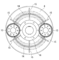
- a rib 14 is formed in an arc shape along the circumferential direction.
- the rib 14 has a shape protruding upward from the surface of the upper surface portion 6.
- a plate-like support portion 15 is provided between the two ports 13 along the radial direction of the upper surface portion 6.
- the support portion 15 has a lower end portion connected to the upper surface portion 6.
- six support portions 15 are provided in the circumferential direction.
- the position and the number of installation of the support part 15 are not limited to this example.
- a notch 17 is formed in the lower portion of the support portion 15 so as not to interfere with the rib 14.
- An annular reinforcing material 16 is further installed inside the plurality of support portions 15.
- the reinforcing member 16 has an outer peripheral edge connected to the support portion 15.
- the deformation adjusting unit 20 is in contact with the upper surface part 6 and applies a pressing force to deform the plate-like member on the upper surface part 6. As a result, the inherent resonance frequency of the quarter wavelength resonator 1 is changed.
- the deformation adjusting unit 20 is provided between the two support units 15 as shown in FIG. FIG. 4 is a longitudinal sectional view cut along the rib 14 of the upper surface portion 6 in the circumferential direction of the upper surface portion 6.
- One or more deformation adjusting units 20 are installed on the upper surface unit 6.
- a plurality of one or more deformation adjusting units 20 are preferably installed at positions that are point-symmetric. By being provided at a symmetrical position, the change in the resonance frequency is stabilized and adjustment is easy. Note that, by appropriately selecting the thickness and shape of the plate-like member of the upper surface portion 6 and the plate-like member of the rib 14, it is possible to stabilize the change of the resonance frequency and facilitate adjustment.
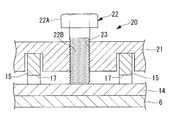
- the deformation adjusting unit 20 includes a base 21 and a bolt 22.
- the base portion 21 is a plate-like or block-like member, and the lower surface is connected to the upper surface of the support portion 15.
- a through hole 23 is formed in the center portion of the base portion 21 in the vertical direction, and a female screw that can be screwed into the bolt 22 is provided inside the through hole 23.
- a head portion 22A is provided on the upper portion of the bolt 22, and a male screw is provided on the rod portion 22B.
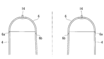
- the bolt 22 When the bolt 22 is moved downward, the lower end portion of the rod portion 22B of the bolt 22 contacts the rib 14 of the upper surface portion 6. Further, by moving the bolt 22 downward, the bolt 22 fixed to the base portion 21 and the support portion 15 applies a pressing force to the rib 14 and the upper surface portion 6. As a result, as shown in FIG. 7, the ribs 14 and the upper surface portion 6 are deformed by the bolts 22. The deformation amount of the rib 14 and the upper surface portion 6 can be changed according to the movement amount of the bolt 22.
- the deformation adjusting unit 20 is not limited to the case having the base part 21, and the bolt 22 may be installed on the support part 15 without providing the base part 21 as shown in FIG. 8.
- the support portion 15 is thickened and the through hole 23 is formed in the vertical direction from the end surface of the plate-like support portion 15. Inside the through hole 23, a female screw that can be screwed into the bolt 22 is provided.
- the lower end portion of the rod portion 22 ⁇ / b> B of the bolt 22 protrudes into the notch 17 and comes into contact with the rib 14 of the upper surface portion 6.
- the bolt 22 fixed to the support portion 15 can apply a pressing force to the rib 14 and the upper surface portion 6 and deform the rib 14 and the upper surface portion 6. Can do.
- the thickness and shape of the plate-like member of the upper surface portion 6 and the plate-like member of the rib 14 it is possible to achieve the deformation assumed in advance for the rib 14 and the upper surface portion 6.
- the deformation adjusting unit 20 may forcibly deform the rib 14 and the upper surface part 6 to plastically deform, or may elastically deform the rib 14 and the upper surface part 6 in an elastic deformation region.
- both plastic deformation and elastic deformation can be considered.
- the rib 14 and the upper surface portion 6 are largely deformed to be plastically deformed. After the plastic deformation, the deformation of the rib 14 and the upper surface portion 6 is maintained even after the bolt 22 of the deformation adjusting portion 20 is moved upward again and the lower end portion of the rod portion 22B of the bolt 22 is separated from the rib 14. Therefore, the resonance frequency of the quarter wavelength resonator 1 is set to a value different from that before the deformation.
- the bolt 22 of the deformation adjusting unit 20 is moved downward, the resonance frequency is adjusted, and then the bolt 22 is fixed at that position to maintain the deformation of the quarter wavelength resonator 1. .
- the rib 14 and the upper surface portion 6 are elastically deformed in the elastic deformation region.
- the bolt 22 of the deformation adjusting unit 20 is moved in the vertical direction in the elastic deformation region of the rib 14 and the upper surface part 6. In this case, the amount of bending of the rib 14 and the upper surface portion 6 changes as the bolt 22 moves in the vertical direction.
- the bolts 22 may be evenly moved for all the deformation adjustment units 20, or the bolts of some of the deformation adjustment units 20 while measuring the change characteristic of the resonance frequency. 22 may be moved, or the amount of movement of each bolt 22 may be varied.
- the rib 14 and the upper surface portion 6 are deformed by the plurality of deformation adjusting portions 20, the deformation shapes of the rib 14 and the upper surface portion 6 can be made different from the case where the pressing force is applied to one position. It becomes easy to finely change the resonance frequency of the quarter wavelength resonator 1.
- the range in which one deformation adjusting unit 20 can be deformed is a range between the two support units 15.
- the base 21 and the bolt 22 of the deformation adjustment unit 20 may be removed from the support unit 15 after completion of tuning before operation.
- the inherent resonance frequency of the quarter wavelength resonator 1 can be changed by deforming the upper surface portion 6 of the quarter wavelength resonator 1. Since the deformation adjusting unit 20 is installed above the quarter wavelength resonator 1 corresponding to the upper surface portion 6 of the quarter wavelength resonator 1, the adjacent quarter wavelength resonators 1 are adjacent to each other. There is no interference with. Therefore, even when the distance between the plurality of quarter wavelength resonators 1 is short and the space between adjacent quarter wavelength resonators 1 is narrow, the resonance frequency is changed using the deformation adjusting unit 20. be able to.
- the beam port of the quarter wavelength resonator is moved inward, and the side surface portion 4 is deformed in a concave shape inward in the beam axis direction. Do not change the position of port 7. Therefore, the inherent resonant frequency of the quarter wavelength resonator 1 can be changed without significantly affecting the acceleration electric field generated inside the quarter wavelength resonator 1.
- this embodiment demonstrated the case where the rib 14 was provided on the surface of the upper surface part 6 in the quarter wavelength resonator 1, this invention is not limited to this example. That is, the ribs 14 may not be provided, and the bolts 22 may contact the upper surface portion 6 and the upper surface portion 6 may be directly deformed by the bolts 22.
- the plate thickness of the upper surface portion 6 with which the bolt 22 abuts may be formed thinner than other portions of the upper surface portion 6, the side surface portion 4, and the like. Thereby, the bolt 22 of the deformation adjusting unit 20 comes into contact, and the plate thickness of the portion where the bolt 22 deforms the upper surface portion 6 is thinner than the other portions, so that the upper surface portion 6 is deformed with a small pressing force. Can do.
- the present embodiment is mainly used when adjusting (tuning) the inherent resonance frequency of the quarter wavelength resonator 1 during operation.
- the quarter wavelength resonator 1 of the superconducting linear accelerator according to the present embodiment differs from the first embodiment in the configuration of the deformation adjusting unit 20.
- transformation adjustment part 20 of the quarter wavelength resonator 1 is demonstrated, and detailed description is abbreviate
- the quarter-wave resonator 1 has been described with reference to the drawings.
- the present invention also applies to a half-wave resonator (HWR: Half Wave Resonator) used in a superconducting linear accelerator. Applicable.
- HWR Half Wave Resonator
- the deformation adjusting unit 20 is disposed outside the container 30.
- the container 30 is filled with, for example, liquid helium.
- the deformation adjustment unit 20 includes a support part 31, a rod part 32, a rod position adjustment part 33, and the like.
- the rod position adjusting unit 33 changes the vertical position of the rod unit 32, and the lower end 32 ⁇ / b> B of the rod unit 32 is brought into contact with the upper surface unit 6 to deform the rib 14 and the upper surface unit 6. .
- a circular opening 30A is formed on the upper surface of the container 30, and the rod 32 is inserted into the opening 30A.
- the support part 31 is a cylindrical member, for example, and a lower end part is installed on the upper surface side of the container 30 along the opening part 30A.
- a flange 34 is provided at the upper end of the support portion 31, and the flange 34 is in contact with the lower surface of the receiving portion 36 of the rod portion 32.
- a bellows 35 is provided at an intermediate portion of the support portion 31, and the bellows 35 enables the flange 34 to move in the vertical direction.
- the rod portion 32 has a receiving portion 36 supported by the support portion 31, a rod-shaped rod 37 extending downward, and a female screw portion 38 in which a female screw hole 39 is formed.
- the receiving portion 36 is, for example, a disk-shaped member, and has a diameter larger than that of the rod 37, and the lower surface side contacts the upper surface of the flange 34 of the support portion 31.
- a rod 37 is connected to the center of the receiving portion 36. The lower end of the rod 37 is brought into contact with the upper surface portion 6 at the lower end portion 32 ⁇ / b> B of the rod portion 32.
- a female screw hole 39 is provided in the center of the female screw portion 38 in the same direction as the axial direction of the rod portion 32, and a female screw is formed inside.
- the female screw part 38 is screwed with the male screw part 40 of the rod position adjusting part 33.
- the rod position adjustment unit 33 includes, for example, a male screw unit 40, a first gear 41, a second gear 42, a motor 43, and the like.
- the motor 43 can rotate forward and backward.
- the first gear 41 is connected to the male screw portion 40, and the second gear 42 is connected to the motor 43.
- the first gear 41 and the second gear 42 mesh with each other.
- the motor 43 is driven, the second gear 42 is rotated, and the rotational force of the second gear 42 is transmitted to the first gear 41.
- the male screw portion 40 rotates.
- the rod portion 32 screwed with the male screw portion 40 moves in the axial direction without rotating around the axial center, and can move downward or upward with respect to the container 30. That is, the rod portion 32 has a configuration in which the rotation around the axis is suppressed and the rod portion 32 is movable in the axial direction, that is, the vertical direction.
- the lower end portion 32B of the rod portion 32 comes into contact with the upper surface portion 6, and the rod portion 32 is further moved downward to deform the upper surface portion 6.
- the amount of deformation of the upper surface portion 6 can be changed according to the amount of movement of the rod portion 32.
- the rod portion 32 deforms the upper surface portion 6
- the rib 14 is provided on the surface of the upper surface portion 6 and the rod portion 32 causes the upper surface portion 6 to be deformed.
- the part 6 and the rib 14 may be deformed.
- the deformation adjustment unit 20 is provided outside the container 30, and the upper surface part 6 of the quarter wavelength resonator 1 is deformed from the outside of the container 30 using the deformation adjustment unit 20. Can do.
- the rod portion 32 can be moved in the vertical direction by driving the motor 43 instead of directly operating the bolt 22 as in the first embodiment. Therefore, even when the container 30 is filled with liquid helium during operation and the quarter-wave resonator 1 is difficult to access, the upper surface portion 6 of the quarter-wave resonator 1 can be deformed by remote control. it can.
Landscapes
- Physics & Mathematics (AREA)
- Engineering & Computer Science (AREA)
- Plasma & Fusion (AREA)
- Spectroscopy & Molecular Physics (AREA)
- Particle Accelerators (AREA)
Abstract
隣接して配置される加速空洞間のスペースを占有することなく、加速空洞が有する固有の共振周波数を変更させることが可能な加速空洞、加速器及び加速空洞の共振周波数調整方法を提供することを目的とする。1/4波長型共振器は、軸方向が鉛直方向に対して平行に配置され、側面部が円筒形状を有する胴体部と、胴体部の上部に設けられ、板状部材である上面部6と、上面部6に対して押圧力を付与し、上面部6を変形させる変形調整部20とを備える。
Description
本発明は、加速空洞、加速器及び加速空洞の共振周波数調整方法に関するものである。
陽子又は重粒子(重イオン)を加速する超伝導線形加速器において、1/4波長型共振器(QWR:Quarter Wave Resonator)又は1/2波長型共振器(HWR:Half Wave Resonator)を用いて加速空洞を形成する場合がある。加速空洞にはマイクロ波を投入して、陽子又は重粒子を加速する加速電場を発生させる。このとき、加速空洞が有する固有の共振周波数を加速電場の周波数に同期させることにより、粒子を効率良く加速させることができる。したがって、加速空洞が有する共振周波数を調整するため、加速空洞をチューニングする必要がある。
下記の特許文献1及び2には、加速空洞のチューニングに関する発明が開示されている。
下記の特許文献1及び2には、加速空洞のチューニングに関する発明が開示されている。
加速空洞のチューニングは、加速器の運転前に実施されるものと、運転中に実施されるものとがある。運転前に実施されるチューニング(以下「プリチューニング」という。)としては、空洞内部に組み込まれる一部の部品の長さを調整すること、空洞自体を塑性変形させて空洞形状を変えること、及び、空洞の内表面を研磨することなどがある。運転前のプリチューニングは、共振周波数が大きな範囲で調整される。
運転中に実施されるチューニングとしては、空洞自体を弾性変形させて空洞形状を可逆的に調整することや、空洞内部に部品を挿入することがある。運転中のチューニングは、運転条件等によってわずかに変わってしまう共振周波数を元に戻すためなどに行われる。
加速空洞を変形させてチューニングする場合、加速空洞に対し、ビーム軸方向であって、加速空洞の内側に凹状に変形させる方法が行われている。加速空洞が複数台直列に配置される場合、空洞間の間隔を短くすることで、加速器の全長に対する加速空洞の割合が大きくなり、加速器全体をコンパクトにすることができる。一方、1/4波長型共振器又は1/2波長型共振器は、剛性が高い構造を有することから、共振器を変形させる機能を有するチューナーは、高い変形力を付与できる規模の大きな構成とする必要がある。チューナーは、例えば、縦長円筒形状の共振器を外周面から挟み込む構造を有する。このとき、チューナーが付与する押圧力は、数十kN単位である。そのため、加速空洞間にチューナーを配置する場合、一定の空間を確保する必要があった。
本発明は、このような事情に鑑みてなされたものであって、加速器の運転中に実施するチューニング又は運転前に実施するプリチューニングにおいて、隣接して配置される加速空洞間のスペースを占有することなく、加速空洞が有する固有の共振周波数を変更させることが可能な加速空洞、加速器及び加速空洞の共振周波数調整方法を提供することを目的とする。
本発明の第1態様に係る加速空洞は、軸方向が鉛直方向に対して平行に配置され、側面部が円筒形状を有する胴体部と、前記胴体部の上部に設けられ、板状部材である上面部と、前記上面部に対して押圧力を付与し、前記上面部を変形させる変形調整部とを備える。
この構成によれば、側面部が円筒形状を有する胴体部は、軸方向が鉛直方向に対して平行に配置され、板状部材である上面部が、胴体部の上部に設けられる。このとき、変形調整部が上面部に対して押圧力を付与して上面部を変形させる。これにより、胴体部の上部に設けられた上面部が変形することから、加速空洞が有する共振周波数が変更される。
上記第1態様において、複数の前記変形調整部が設けられてもよく、それぞれの前記変形調整部が前記上面部の異なる位置に対し押圧力を付与してもよい。
この構成によれば、複数の変形調整部によって、上面部の複数の位置に対し押圧力を付与できる。その結果、一の位置に対し押圧力を付与する場合と比べて、上面部の変形形状を異ならせることができるため、加速空洞の共振周波数を細かく変更しやすくなる。例えば、上面部が円環形状であるとき、複数の変形調整部は、上面部の周方向に沿って、それぞれの変形調整部が間隔を空けて設けられる。
上記第1態様において、前記上面部の面上に上方に突出したリブが設けられてもよく、前記変形調整部は、前記リブに接触して押圧力を付与してもよい。
この構成によれば、変形調整部が上面部に設けられたリブに接触しており、リブに対して押圧力を付与して上面部を変形させる。このとき、リブを介して押圧力が上面部の面内に広く伝達されるため、リブの長手方向に沿って変形部分を増やすことができる。
上記第1態様において、前記上面部は、前記変形調整部が接触する部分の板厚が他の部分よりも薄くてもよい。
この構成によれば、変形調整部が接触して押圧力が付与される部分の板厚が、他の部分よりも薄いため、少ない押圧力で上面部を変形させることができる。
上記第1態様において、前記上面部は、前記変形調整部が接触する部分が平面状に形成されてもよい。
この構成によれば、変形調整部が接触して押圧力が付与される部分が、断面が直線である平面状に形成されるため、断面が円弧形状等の曲面で形成される場合に比べて、少ない押圧力で上面部を変形させることができる。
本発明の第2態様に係る加速器は、上記第1態様の加速空洞を備える。
本発明の第3態様に係る加速空洞の共振周波数調整方法は、軸方向が鉛直方向に対して平行に配置され、側面部が円筒形状を有する胴体部と、前記胴体部の上部に設けられ、板状部材である上面部とを備える加速空洞の共振周波数調整方法であって、変形調整部が、前記上面部に対して押圧力を付与し、前記上面部を変形させるステップを有する。
上記第3態様における前記上面部を変形させるステップにおいて、前記上面部を塑性変形、又は、弾性変形させる。
上記第3態様において、複数の前記変形調整部が設けられるとき、全ての又は一部の前記変形調整部によって前記上面部を変形させる。
本発明によれば、加速空洞の胴体部の上部に設けられた上面部を変形させることから、変形調整部が、隣接して配置される加速空洞間のスペースを占有することなく、加速空洞が有する固有の共振周波数を変更させることができる。
以下に、本発明に係る実施形態について、図面を参照して説明する。
[第1実施形態]
以下、本発明の第1実施形態に係る超伝導線形加速器について、図1から図8を用いて説明する。
本実施形態に係る超伝導線形加速器は、陽子又は重粒子(重イオン)を加速する。超伝導線形加速器は、1/4波長型共振器(QWR:Quarter Wave Resonator)1を用いて加速空洞が形成される。1/4波長型共振器1は、1台で用いられる場合と、複数台が直列に接続されて用いられる場合がある。1/4波長型共振器1にはマイクロ波が投入されて、1/4波長型共振器1内には陽子又は重粒子を加速する加速電場が発生する。なお、以下では、1/4波長型共振器1について、図面を用いて説明したが、本発明は、超伝導線形加速器に用いられる1/2波長型共振器(HWR:Half Wave Resonator)にも適用できる。
1/4波長型共振器1は、ニオブ製であり、側面が円筒形状である胴体部2と、胴体部2の内部に設けられる中心導体3などを備える。
胴体部2は、外周面が円筒形状の側面部4と、側面部4に接続された下面部5及び上面部6を有する。側面部4、下面部5及び上面部6は、例えば板厚3mm~4mmの板状部材で構成される。胴体部2の内部は、胴体部2の側面部4、下面部5及び上面部6と、中心導体3によって閉鎖された空間となっている。
下面部5は、平面視が円形状であって、例えば椀形状又は平板状である。上面部6は、平面視が円環形状であって、縦断面形状は、上側に凸状である曲面を有する。なお、上面部6は曲面のみではなく、平面部を有してもよい。
上面部6の外周縁6aは、側面部4の上部と接続され、上面部6の内周縁6bは中心導体3の上部と接続される。
胴体部2の下部には、陽子又は重粒子が通過する開口部8が形成された、一対のビームポート7が設けられる。各ビームポート7は、端部にフランジ9が形成されており、他の1/4波長型共振器のビームポート7に対し接続部品(図示せず。)を介して接続可能である。
ビームポート7は、胴体部2の側面部4から突出し、胴体部2の軸方向に対して垂直方向に設けられる。二つのビームポート7は、同軸上に設けられており、内部に形成される開口部8も同軸に配置される。
中心導体3は、テーパ形状の接続部10と、内部に開口部12を有する円環形状のビーム通過部11を有する。接続部10は、上方の直径が大きく、下方の直径が小さいテーパ形状である。接続部10の下部とビーム通過部11の上部は、連続して接続されており、接続部10の内部とビーム通過部11の内部には、連続した一つの空間が形成され、加速器の運転時において、例えば液体ヘリウムが充填される。なお、接続部10は、上方の直径と下方の直径が同一である円筒形状であってもよい。
ビーム通過部11は、二つの椀形部材が合わさった形状を有し、ビームポート7側に向かって凸状の曲面を有する。ビーム通過部11の中心部には、円筒状の開口部12が形成されており、開口部12の両端は、ビーム通過部11のビームポート7側の面と接続されている。ビーム通過部11の開口部12は、ビームポート7の開口部8と同軸上に設けられる。ビーム通過部11の開口部12の内部は、陽子又は重粒子が通過する。
ビーム通過部11のビーム軸方向の厚みや、開口部12のビーム軸方向の長さは、接続部10の最下端の直径よりも長く、接続部10とビーム通過部11の接続部分は屈曲した形状を有している。なお、接続部10とビーム通過部11の接続部分の形状は、屈曲形状を有する場合に限定されない。ビーム通過部11のビーム軸方向の厚みや、開口部12のビーム軸方向の長さが、円筒形状の接続部10の直径と同一である場合もある。また、ビーム通過部11は、円環形状である場合に限られず、円筒形状の接続部10と同一直径の円筒形状であって、円筒外周面を貫通するように開口部12が形成されるものであってもよい。
胴体部2の側面部4と中心導体3の側面との間や、胴体部2の下面部5と中心導体3の最下端との間には、空間が設けられる。1/4波長型共振器1の横断面形状は、胴体部2の側面部4と中心導体3の側面との間の空間は、円環形状となっている。
1/4波長型共振器1の外側には、金属製の容器(ジャケット)30が設けられ、容器30内部と胴体部2の外周部との間に、例えば液体ヘリウムが充填される。
胴体部2の上面部6には、一対のポート13が、胴体部2の軸方向に対して平行方向に設けられる。ポート13は、1/4波長型共振器1の製造時における内部空間の洗浄や研磨に用いられる。
また、胴体部2の上面部6において、二つのポート13の間には、周方向に沿って、円弧状にリブ14が形成される。リブ14は、上面部6の面から上方へ突出した形状を有する。リブ14が設けられることにより、変形調整部20のボルト22による押圧力が、リブ14を介して上面部6の面内に広く伝達されるため、リブ14の長手方向に沿って変形部分を増やすことができる。
また、二つのポート13の間には、上面部6の径方向に沿って、板状の支持部15が設けられる。支持部15は、下端部が上面部6と接続されている。図3に示す例では、支持部15が周方向に6箇所設けられている。なお、支持部15の位置や設置数は、この例に限定されない。なお、支持部15の下部には、リブ14と干渉しないように切欠き17が形成されている。
複数の支持部15の内側には、更に円環状の補強材16が設置される。補強材16は、外周縁が支持部15と接続されている。
次に、図3から図8を用いて、本実施形態に係る変形調整部20について説明する。
変形調整部20は、上面部6に接触して押圧力を付与し、上面部6の板状部材を変形させる。これにより、1/4波長型共振器1が有する固有の共振周波数が変更される。
変形調整部20は、上面部6に接触して押圧力を付与し、上面部6の板状部材を変形させる。これにより、1/4波長型共振器1が有する固有の共振周波数が変更される。
変形調整部20は、図4に示すように、二つの支持部15間に設けられる。図4は、上面部6のリブ14に沿って、上面部6の周方向に切断した縦断面図である。変形調整部20は、上面部6において、一つ以上設置される。複数の変形調整部20が設けられる場合は、二つの支持部15間それぞれに一つずつ設置される。変形調整部20は、好ましくは点対称となる位置に、一対以上、複数設置される。対称となる位置に設けられることで、共振周波数の変化が安定し、調整を行いやすい。なお、上面部6の板状部材やリブ14の板状部材の厚さや形状を適宜選定することによっても、共振周波数の変化を安定させ、調整を行いやすくさせることができる。
変形調整部20は、台部21と、ボルト22を有する。台部21は、板状又はブロック状の部材であり、下面が支持部15の上面と接続される。台部21の中心部には、貫通孔23が上下方向に形成されており、貫通孔23の内部には、ボルト22と螺合可能な雌ねじが設けられる。ボルト22の上部には頭部22Aが設けられ、ロッド部22Bには雄ねじが設けられる。頭部22Aを回転させることによって、ボルト22は、軸方向に移動し、台部21に対し下方向又は上方向に移動可能である。
ボルト22を下方向に移動させることにより、ボルト22のロッド部22Bの下端部が上面部6のリブ14に当接する。更にボルト22を下方向に移動させることにより、台部21及び支持部15に固定されたボルト22は、リブ14及び上面部6に対し押圧力を付与する。その結果、図7に示すように、ボルト22によって、リブ14及び上面部6が変形する。ボルト22の移動量に応じて、リブ14及び上面部6の変形量を変化させることができる。
なお、変形調整部20は、台部21を有する場合に限定されず、図8に示すように、台部21を設けずに、ボルト22が支持部15に設置されるようにしてもよい。この場合、支持部15は、板厚を厚くして、板状の支持部15の端面から上下方向に貫通孔23が形成される。貫通孔23の内部には、ボルト22と螺合可能な雌ねじが設けられる。ボルト22のロッド部22Bの下端部は、切欠き17へ突き出て、上面部6のリブ14に当接する。この場合も、ボルト22を下方向に移動させることにより、支持部15に固定されたボルト22は、リブ14及び上面部6に対し押圧力を付与でき、リブ14及び上面部6を変形させることができる。上面部6の板状部材やリブ14の板状部材の厚さや形状を適宜選定することによって、リブ14及び上面部6に対して、予め想定しておいた変形を達成することができる。
変形調整部20は、リブ14及び上面部6を強制的に変形させて塑性変形させてもよいし、リブ14及び上面部6を弾性変形域で弾性変形させてもよい。
例えば、運転前に1/4波長型共振器1の固有の共振周波数を調整(プリチューニング)する場合、塑性変形と弾性変形の両方が考えられる。
塑性変形の場合は、リブ14及び上面部6を大きく変形させて、塑性変形させる。塑性変形後は、変形調整部20のボルト22を再び上方に移動させて、ボルト22のロッド部22Bの下端部をリブ14から離した後もリブ14及び上面部6の変形は維持される。したがって、1/4波長型共振器1が有する共振周波数が、変形前と異なる値に設定される。
弾性変形の場合は、変形調整部20のボルト22を下向きに移動させ、共振周波数を調整した後、その位置でボルト22を固定することで1/4波長型共振器1の変形が維持される。
塑性変形の場合は、リブ14及び上面部6を大きく変形させて、塑性変形させる。塑性変形後は、変形調整部20のボルト22を再び上方に移動させて、ボルト22のロッド部22Bの下端部をリブ14から離した後もリブ14及び上面部6の変形は維持される。したがって、1/4波長型共振器1が有する共振周波数が、変形前と異なる値に設定される。
弾性変形の場合は、変形調整部20のボルト22を下向きに移動させ、共振周波数を調整した後、その位置でボルト22を固定することで1/4波長型共振器1の変形が維持される。
また、運転中に1/4波長型共振器1の固有の共振周波数を調整(チューニング)する場合、リブ14及び上面部6を弾性変形域で弾性変形させる。変形調整部20のボルト22は、リブ14及び上面部6の弾性変形域で上下方向に移動される。この場合、ボルト22の上下方向の移動に伴って、リブ14及び上面部6の撓み量が変化する。
複数の変形調整部20が設置される場合、全ての変形調整部20についてボルト22を均等に移動させてもよいし、共振周波数の変化特性を測定しながら、一部の変形調整部20のボルト22を移動させたり、それぞれのボルト22の移動量を異ならせてもよい。複数の変形調整部20によってリブ14及び上面部6を変形させる場合、一の位置に対し押圧力を付与する場合と比べて、リブ14及び上面部6の変形形状を異ならせることができるため、1/4波長型共振器1が有する共振周波数を細かく変更しやすくなる。図6の網掛け部分は、上面部6に対し四つの変形調整部20を設置し、全ての変形調整部20を用いて上面部6を変形させた場合の変形範囲を示す。なお、一つの変形調整部20が変形可能な範囲は、二つの支持部15間の範囲となる。
なお、運転中にチューニングを行わない場合は、運転前のチューニング完了後、変形調整部20の台部21及びボルト22を支持部15から取り外してもよい。
以上、本実施形態によれば、1/4波長型共振器1の上面部6を変形することによって、1/4波長型共振器1が有する固有の共振周波数を変更することができる。変形調整部20は、1/4波長型共振器1の上面部6に対応して、1/4波長型共振器1の上方に設置されることから、隣り合う1/4波長型共振器1と干渉することがない。したがって、複数の1/4波長型共振器1の間の距離が短く、隣り合う1/4波長型共振器1の間の空間が狭い場合でも、変形調整部20を用いて共振周波数を変更することができる。
また、本実施形態は、従来のように、1/4波長型共振器のビームポートを内側に移動させて、側面部4をビーム軸方向であって内側に凹状に変形させる場合と異なり、ビームポート7の位置を変更しない。したがって、1/4波長型共振器1の内部に発生する加速電場に大きな影響を与えることなく、1/4波長型共振器1が有する固有の共振周波数を変更することができる。
なお、本実施形態では、1/4波長型共振器1において、上面部6の面上にリブ14が設けられる場合について説明したが、本発明はこの例に限定されない。すなわち、リブ14が設けられず、ボルト22が上面部6に当接し、ボルト22によって上面部6が直接変形されるとしてもよい。
また、ボルト22が当接する上面部6の板厚が、上面部6の他の部分や側面部4などよりも薄く形成されてもよい。これにより、変形調整部20のボルト22が接触して、ボルト22が上面部6を変形させる部分の板厚が、他の部分よりも薄いことから、少ない押圧力で上面部6を変形させることができる。
[第2実施形態]
次に、本発明の第2実施形態に係る超伝導線形加速器について説明する。
本実施形態は、運転中に1/4波長型共振器1の固有の共振周波数を調整(チューニング)する場合に主に使用される。
本実施形態に係る超伝導線形加速器の1/4波長型共振器1は、第1実施形態と比べて、変形調整部20の構成が異なる。以下では、1/4波長型共振器1の変形調整部20について説明し、第1実施形態と重複する構成要素及び作用効果については詳細な説明を省略する。なお、以下では、1/4波長型共振器1について、図面を用いて説明したが、本発明は、超伝導線形加速器に用いられる1/2波長型共振器(HWR:Half Wave Resonator)にも適用できる。
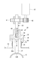
変形調整部20は、図9に示すように、容器30よりも外側に配置される。容器30には、例えば液体ヘリウムが充填される。
変形調整部20は、支持部31と、ロッド部32と、ロッド位置調整部33などを有する。変形調整部20は、ロッド位置調整部33がロッド部32の上下方向の位置を変更し、ロッド部32の下端部32Bを上面部6に当接させて、リブ14及び上面部6を変形させる。
変形調整部20は、支持部31と、ロッド部32と、ロッド位置調整部33などを有する。変形調整部20は、ロッド位置調整部33がロッド部32の上下方向の位置を変更し、ロッド部32の下端部32Bを上面部6に当接させて、リブ14及び上面部6を変形させる。
容器30の上面には、例えば円形の開口部30Aが形成され、開口部30Aにはロッド部32が挿通される。支持部31は、例えば円筒状部材であり、下端部が開口部30Aに沿って、容器30の上面側に設置される。支持部31の上端部には、フランジ34が設けられ、フランジ34はロッド部32の受け部36の下面と接触している。支持部31の中間部分には、ベローズ35が設けられ、ベローズ35は、フランジ34の上下方向の移動を可能とする。
ロッド部32は、支持部31に支持される受け部36と、下方に延設される棒状のロッド37と、雌ねじ穴39が形成された雌ねじ部38を有する。
受け部36は、例えば円板状部材であって、ロッド37よりも径が大きく、下面側が支持部31のフランジ34の上面と接触する。また、受け部36の中心にはロッド37が接続される。ロッド37の下端は、ロッド部32の下端部32Bを上面部6に当接される。雌ねじ部38の中心には、ロッド部32の軸方向と同一方向に雌ねじ穴39が設けられており、内部には雌ねじが形成される。雌ねじ部38は、ロッド位置調整部33の雄ねじ部40と螺合される。
ロッド位置調整部33は、例えば、雄ねじ部40と、第1ギア41と、第2ギア42と、モータ43などを有する。モータ43は、正回転及び逆回転が可能である。
第1ギア41は、雄ねじ部40と接続され、第2ギア42はモータ43と接続される。第1ギア41と第2ギア42は、互いに噛み合っている。モータ43が駆動することによって、第2ギア42が回転し、第2ギア42の回転力が第1ギア41に伝達される。そして、第1ギア41が回転することによって、雄ねじ部40が回転する。その結果、雄ねじ部40と螺合しているロッド部32は、軸心周りに回転せずに、軸方向に移動し、容器30に対し下方向又は上方向に移動可能である。すなわち、ロッド部32は、軸心周りの回転が抑制され、軸方向、すなわち上下方向に移動可能な構成を有している。
ロッド部32を下方向に移動させることにより、ロッド部32の下端部32Bが上面部6に当接し、更にロッド部32を下方向に移動させることにより、上面部6を変形させる。ロッド部32の移動量に応じて、上面部6の変形量を変化させることができる。
なお、本実施形態では、ロッド部32が上面部6を変形させる場合について説明したが、第1実施形態と同様に、上面部6の面上にリブ14が設けられて、ロッド部32によって上面部6及びリブ14が変形されるとしてもよい。
本実施形態によれば、変形調整部20が容器30の外部に設けられ、容器30の外部側から、変形調整部20を用いて1/4波長型共振器1の上面部6を変形することができる。
また、第1実施形態のようにボルト22を直接操作するのではなく、モータ43を駆動することによってロッド部32を上下方向に移動させることができる。そのため、運転中、容器30に液体ヘリウムが充填され、1/4波長型共振器1にアクセスしにくい場合においても、遠隔操作によって1/4波長型共振器1の上面部6を変形することができる。
1 1/4波長型共振器
2 胴体部
3 中心導体
4 側面部
5 下面部
6 上面部
7 ビームポート
8,12 開口部
9 フランジ
10 接続部
11 ビーム通過部
13 ポート
14 リブ
15 支持部
20 変形調整部
21 台部
22 ボルト
30 容器
31 支持部
32 ロッド部
33 ロッド位置調整部
34 フランジ
35 ベローズ
36 受け部
37 ロッド
38 雌ねじ部
39 雌ねじ穴
40 雄ねじ部
41 第1ギア
42 第2ギア
43 モータ
2 胴体部
3 中心導体
4 側面部
5 下面部
6 上面部
7 ビームポート
8,12 開口部
9 フランジ
10 接続部
11 ビーム通過部
13 ポート
14 リブ
15 支持部
20 変形調整部
21 台部
22 ボルト
30 容器
31 支持部
32 ロッド部
33 ロッド位置調整部
34 フランジ
35 ベローズ
36 受け部
37 ロッド
38 雌ねじ部
39 雌ねじ穴
40 雄ねじ部
41 第1ギア
42 第2ギア
43 モータ
Claims (9)
- 軸方向が鉛直方向に対して平行に配置され、側面部が円筒形状を有する胴体部と、
前記胴体部の上部に設けられ、板状部材である上面部と、
前記上面部に対して押圧力を付与し、前記上面部を変形させる変形調整部と、
を備える加速空洞。 - 複数の前記変形調整部が設けられ、それぞれの前記変形調整部が前記上面部の異なる位置に対し押圧力を付与する請求項1に記載の加速空洞。
- 前記上面部の面上に上方に突出したリブが設けられ、
前記変形調整部は、前記リブに接触して押圧力を付与する請求項1又は2に記載の加速空洞。 - 前記上面部は、前記変形調整部が接触する部分の板厚が他の部分よりも薄い請求項1から3のいずれか1項に記載の加速空洞。
- 前記上面部は、前記変形調整部が接触する部分が平面状に形成される請求項1から4のいずれか1項に記載の加速空洞。
- 請求項1から5のいずれか1項に記載の加速空洞を備える加速器。
- 軸方向が鉛直方向に対して平行に配置され、側面部が円筒形状を有する胴体部と、前記胴体部の上部に設けられ、板状部材である上面部とを備える加速空洞の共振周波数調整方法であって、
変形調整部が、前記上面部に対して押圧力を付与し、前記上面部を変形させるステップを有する加速空洞の共振周波数調整方法。 - 前記上面部を変形させるステップにおいて、前記上面部を塑性変形、又は、弾性変形させる請求項7に記載の加速空洞の共振周波数調整方法。
- 複数の前記変形調整部が設けられるとき、全ての又は一部の前記変形調整部によって前記上面部を変形させる請求項7又は8に記載の加速空洞の共振周波数調整方法。
Priority Applications (3)
| Application Number | Priority Date | Filing Date | Title |
|---|---|---|---|
| KR1020187030571A KR102195011B1 (ko) | 2016-05-06 | 2017-05-01 | 가속 공동, 가속기 및 가속 공동의 공진 주파수 조정 방법 |
| EP17792769.6A EP3454629B1 (en) | 2016-05-06 | 2017-05-01 | Acceleration cavity, accelerator, and method for adjusting resonance frequency of acceleration cavity |
| US16/097,706 US10609807B2 (en) | 2016-05-06 | 2017-05-01 | Acceleration cavity, accelerator, and resonance frequency adjustment method of acceleration cavity |
Applications Claiming Priority (2)
| Application Number | Priority Date | Filing Date | Title |
|---|---|---|---|
| JP2016093220A JP6800607B2 (ja) | 2016-05-06 | 2016-05-06 | 加速空洞、加速器及び加速空洞の共振周波数調整方法 |
| JP2016-093220 | 2016-05-06 |
Publications (1)
| Publication Number | Publication Date |
|---|---|
| WO2017191837A1 true WO2017191837A1 (ja) | 2017-11-09 |
Family
ID=60203540
Family Applications (1)
| Application Number | Title | Priority Date | Filing Date |
|---|---|---|---|
| PCT/JP2017/017207 Ceased WO2017191837A1 (ja) | 2016-05-06 | 2017-05-01 | 加速空洞、加速器及び加速空洞の共振周波数調整方法 |
Country Status (5)
| Country | Link |
|---|---|
| US (1) | US10609807B2 (ja) |
| EP (1) | EP3454629B1 (ja) |
| JP (1) | JP6800607B2 (ja) |
| KR (1) | KR102195011B1 (ja) |
| WO (1) | WO2017191837A1 (ja) |
Cited By (1)
| Publication number | Priority date | Publication date | Assignee | Title |
|---|---|---|---|---|
| CN109362171A (zh) * | 2018-11-14 | 2019-02-19 | 中国原子能科学研究院 | 一种谐振腔频率自动调谐装置 |
Families Citing this family (3)
| Publication number | Priority date | Publication date | Assignee | Title |
|---|---|---|---|---|
| KR102019878B1 (ko) * | 2018-02-09 | 2019-09-09 | 한국원자력연구원 | 고주파 가속관 셀용 고주파 특성 측정 및 튜닝 장치 |
| JP7316837B2 (ja) * | 2019-05-16 | 2023-07-28 | 三菱重工機械システム株式会社 | 二重管の溶接方法 |
| JP7209293B2 (ja) * | 2019-05-17 | 2023-01-20 | 三菱重工機械システム株式会社 | 加速空洞 |
Citations (2)
| Publication number | Priority date | Publication date | Assignee | Title |
|---|---|---|---|---|
| JPH0315199A (ja) * | 1989-06-12 | 1991-01-23 | Mitsubishi Electric Corp | 超電導高周波加速空洞 |
| JP2008117667A (ja) * | 2006-11-06 | 2008-05-22 | High Energy Accelerator Research Organization | 空洞の形状調整装置及び加速空洞の周波数調整装置 |
Family Cites Families (9)
| Publication number | Priority date | Publication date | Assignee | Title |
|---|---|---|---|---|
| DE19934392C2 (de) * | 1999-07-22 | 2001-10-11 | Rossendorf Forschzent | Abstimmgerät für Hohlraumresonatoren |
| US6657515B2 (en) * | 2001-06-18 | 2003-12-02 | Energen, Llp | Tuning mechanism for a superconducting radio frequency particle accelerator cavity |
| US6876278B2 (en) * | 2003-04-23 | 2005-04-05 | Harris Corporation | Tunable resonant cavity |
| EP2624277B1 (en) * | 2010-09-27 | 2019-06-26 | Inter-University Research Institute Corporation High Energy Accelerator Research Organization | Photo-cathode high-frequency electron-gun cavity apparatus |
| US10524346B2 (en) * | 2015-03-02 | 2019-12-31 | The Secretary, Department Of Atomic Energy | Device for tuning SCRF cavity |
| JP6523047B2 (ja) * | 2015-05-29 | 2019-05-29 | 三菱重工機械システム株式会社 | シールド体、及び超伝導加速器 |
| JP5985011B1 (ja) * | 2015-06-30 | 2016-09-06 | 三菱重工メカトロシステムズ株式会社 | 超伝導加速器 |
| JP2017017207A (ja) * | 2015-07-02 | 2017-01-19 | 株式会社ディスコ | ウェーハ保持装置 |
| JP6612143B2 (ja) * | 2016-02-05 | 2019-11-27 | 三菱重工機械システム株式会社 | 加速空洞用入力カプラ及び加速器 |
-
2016
- 2016-05-06 JP JP2016093220A patent/JP6800607B2/ja active Active
-
2017
- 2017-05-01 EP EP17792769.6A patent/EP3454629B1/en active Active
- 2017-05-01 KR KR1020187030571A patent/KR102195011B1/ko active Active
- 2017-05-01 US US16/097,706 patent/US10609807B2/en active Active
- 2017-05-01 WO PCT/JP2017/017207 patent/WO2017191837A1/ja not_active Ceased
Patent Citations (2)
| Publication number | Priority date | Publication date | Assignee | Title |
|---|---|---|---|---|
| JPH0315199A (ja) * | 1989-06-12 | 1991-01-23 | Mitsubishi Electric Corp | 超電導高周波加速空洞 |
| JP2008117667A (ja) * | 2006-11-06 | 2008-05-22 | High Energy Accelerator Research Organization | 空洞の形状調整装置及び加速空洞の周波数調整装置 |
Non-Patent Citations (1)
| Title |
|---|
| TAKAHIRO INAGAKI: "Daidenryoku Koshuhagen", OHO'13 KO ENERGY KASOKUKI SEMINOR TEXT, KO ENERGY KASOKUKI SEMINOR JIMUKYOKU, 23 July 2013 (2013-07-23), pages 1 - 56, XP009516431 * |
Cited By (2)
| Publication number | Priority date | Publication date | Assignee | Title |
|---|---|---|---|---|
| CN109362171A (zh) * | 2018-11-14 | 2019-02-19 | 中国原子能科学研究院 | 一种谐振腔频率自动调谐装置 |
| CN109362171B (zh) * | 2018-11-14 | 2024-05-10 | 中国原子能科学研究院 | 一种谐振腔频率自动调谐装置 |
Also Published As
| Publication number | Publication date |
|---|---|
| US10609807B2 (en) | 2020-03-31 |
| KR102195011B1 (ko) | 2020-12-28 |
| US20190191539A1 (en) | 2019-06-20 |
| JP6800607B2 (ja) | 2020-12-16 |
| EP3454629B1 (en) | 2021-11-24 |
| EP3454629A4 (en) | 2020-01-15 |
| EP3454629A1 (en) | 2019-03-13 |
| JP2017201602A (ja) | 2017-11-09 |
| KR20180127438A (ko) | 2018-11-28 |
Similar Documents
| Publication | Publication Date | Title |
|---|---|---|
| WO2017191837A1 (ja) | 加速空洞、加速器及び加速空洞の共振周波数調整方法 | |
| CN100401578C (zh) | 调谐螺钉组件 | |
| US8173976B2 (en) | Linear ion processing apparatus with improved mechanical isolation and assembly | |
| US20150035623A1 (en) | Variable high frequency filter device and assembly | |
| US10383204B2 (en) | Superconducting accelerator | |
| EP0987787A2 (en) | Microwave cavity having a removable end wall | |
| US11337298B2 (en) | Radio frequency electron accelerator for local frequency modulation and frequency modulation method thereof | |
| US3379922A (en) | Tunable coupled cavity extended interaction electronic tube having deformable end wall | |
| KR20190119929A (ko) | Pimd로 인한 성능 저하에 강인한rf 캐비티 필터 및 rf 캐비티 필터 제조 방법 | |
| US9000670B2 (en) | Harmonic mode magnetron | |
| US5041801A (en) | Magnetron tuning systems | |
| JPH06103905A (ja) | クライストロン用同調機構 | |
| JP6178635B2 (ja) | マグネトロン | |
| US2800609A (en) | Magnetron tuner device | |
| WO2012162948A1 (en) | A cavity microwave filter assembly, and a method for making a cavity microwave filter assembly | |
| JP2610311B2 (ja) | 多連結高周波加速空胴 | |
| JPH0578891B2 (ja) | ||
| US8330345B2 (en) | Active electronically steered cathode emission | |
| JP2008522380A (ja) | マグネトロン | |
| US2635212A (en) | Tunable magnetron | |
| JPH0537394Y2 (ja) | ||
| JP2018121227A (ja) | 空胴共振器及びその製造方法 | |
| AU2013201539C1 (en) | System for producing electromagnetic radiation. | |
| JP2022160053A (ja) | 加速空洞 | |
| JPH0527946U (ja) | 多空胴形クライストロン |
Legal Events
| Date | Code | Title | Description |
|---|---|---|---|
| ENP | Entry into the national phase |
Ref document number: 20187030571 Country of ref document: KR Kind code of ref document: A |
|
| NENP | Non-entry into the national phase |
Ref country code: DE |
|
| 121 | Ep: the epo has been informed by wipo that ep was designated in this application |
Ref document number: 17792769 Country of ref document: EP Kind code of ref document: A1 |
|
| ENP | Entry into the national phase |
Ref document number: 2017792769 Country of ref document: EP Effective date: 20181206 |