WO2017191839A1 - ゴム部材、タイヤおよびゴム部材の製造方法 - Google Patents
ゴム部材、タイヤおよびゴム部材の製造方法 Download PDFInfo
- Publication number
- WO2017191839A1 WO2017191839A1 PCT/JP2017/017216 JP2017017216W WO2017191839A1 WO 2017191839 A1 WO2017191839 A1 WO 2017191839A1 JP 2017017216 W JP2017017216 W JP 2017017216W WO 2017191839 A1 WO2017191839 A1 WO 2017191839A1
- Authority
- WO
- WIPO (PCT)
- Prior art keywords
- rubber
- rubber member
- color
- fine
- uneven
- Prior art date
- Legal status (The legal status is an assumption and is not a legal conclusion. Google has not performed a legal analysis and makes no representation as to the accuracy of the status listed.)
- Ceased
Links
Images
Classifications
-
- B—PERFORMING OPERATIONS; TRANSPORTING
- B60—VEHICLES IN GENERAL
- B60C—VEHICLE TYRES; TYRE INFLATION; TYRE CHANGING; CONNECTING VALVES TO INFLATABLE ELASTIC BODIES IN GENERAL; DEVICES OR ARRANGEMENTS RELATED TO TYRES
- B60C13/00—Tyre sidewalls; Protecting, decorating, marking, or the like, thereof
- B60C13/001—Decorating, marking or the like
-
- B—PERFORMING OPERATIONS; TRANSPORTING
- B29—WORKING OF PLASTICS; WORKING OF SUBSTANCES IN A PLASTIC STATE IN GENERAL
- B29C—SHAPING OR JOINING OF PLASTICS; SHAPING OF MATERIAL IN A PLASTIC STATE, NOT OTHERWISE PROVIDED FOR; AFTER-TREATMENT OF THE SHAPED PRODUCTS, e.g. REPAIRING
- B29C59/00—Surface shaping of articles, e.g. embossing; Apparatus therefor
- B29C59/02—Surface shaping of articles, e.g. embossing; Apparatus therefor by mechanical means, e.g. pressing
-
- B—PERFORMING OPERATIONS; TRANSPORTING
- B29—WORKING OF PLASTICS; WORKING OF SUBSTANCES IN A PLASTIC STATE IN GENERAL
- B29D—PRODUCING PARTICULAR ARTICLES FROM PLASTICS OR FROM SUBSTANCES IN A PLASTIC STATE
- B29D30/00—Producing pneumatic or solid tyres or parts thereof
- B29D30/06—Pneumatic tyres or parts thereof (e.g. produced by casting, moulding, compression moulding, injection moulding, centrifugal casting)
- B29D30/72—Side-walls
-
- B—PERFORMING OPERATIONS; TRANSPORTING
- B60—VEHICLES IN GENERAL
- B60C—VEHICLE TYRES; TYRE INFLATION; TYRE CHANGING; CONNECTING VALVES TO INFLATABLE ELASTIC BODIES IN GENERAL; DEVICES OR ARRANGEMENTS RELATED TO TYRES
- B60C1/00—Tyres characterised by the chemical composition or the physical arrangement or mixture of the composition
-
- B—PERFORMING OPERATIONS; TRANSPORTING
- B60—VEHICLES IN GENERAL
- B60C—VEHICLE TYRES; TYRE INFLATION; TYRE CHANGING; CONNECTING VALVES TO INFLATABLE ELASTIC BODIES IN GENERAL; DEVICES OR ARRANGEMENTS RELATED TO TYRES
- B60C1/00—Tyres characterised by the chemical composition or the physical arrangement or mixture of the composition
- B60C1/0025—Compositions of the sidewalls
-
- B—PERFORMING OPERATIONS; TRANSPORTING
- B60—VEHICLES IN GENERAL
- B60C—VEHICLE TYRES; TYRE INFLATION; TYRE CHANGING; CONNECTING VALVES TO INFLATABLE ELASTIC BODIES IN GENERAL; DEVICES OR ARRANGEMENTS RELATED TO TYRES
- B60C13/00—Tyre sidewalls; Protecting, decorating, marking, or the like, thereof
-
- C—CHEMISTRY; METALLURGY
- C08—ORGANIC MACROMOLECULAR COMPOUNDS; THEIR PREPARATION OR CHEMICAL WORKING-UP; COMPOSITIONS BASED THEREON
- C08K—Use of inorganic or non-macromolecular organic substances as compounding ingredients
- C08K3/00—Use of inorganic substances as compounding ingredients
- C08K3/02—Elements
- C08K3/04—Carbon
-
- C—CHEMISTRY; METALLURGY
- C08—ORGANIC MACROMOLECULAR COMPOUNDS; THEIR PREPARATION OR CHEMICAL WORKING-UP; COMPOSITIONS BASED THEREON
- C08K—Use of inorganic or non-macromolecular organic substances as compounding ingredients
- C08K3/00—Use of inorganic substances as compounding ingredients
- C08K3/34—Silicon-containing compounds
- C08K3/36—Silica
-
- C—CHEMISTRY; METALLURGY
- C08—ORGANIC MACROMOLECULAR COMPOUNDS; THEIR PREPARATION OR CHEMICAL WORKING-UP; COMPOSITIONS BASED THEREON
- C08L—COMPOSITIONS OF MACROMOLECULAR COMPOUNDS
- C08L19/00—Compositions of rubbers not provided for in groups C08L7/00 - C08L17/00
-
- C—CHEMISTRY; METALLURGY
- C08—ORGANIC MACROMOLECULAR COMPOUNDS; THEIR PREPARATION OR CHEMICAL WORKING-UP; COMPOSITIONS BASED THEREON
- C08L—COMPOSITIONS OF MACROMOLECULAR COMPOUNDS
- C08L7/00—Compositions of natural rubber
-
- C—CHEMISTRY; METALLURGY
- C08—ORGANIC MACROMOLECULAR COMPOUNDS; THEIR PREPARATION OR CHEMICAL WORKING-UP; COMPOSITIONS BASED THEREON
- C08L—COMPOSITIONS OF MACROMOLECULAR COMPOUNDS
- C08L9/00—Compositions of homopolymers or copolymers of conjugated diene hydrocarbons
-
- B—PERFORMING OPERATIONS; TRANSPORTING
- B29—WORKING OF PLASTICS; WORKING OF SUBSTANCES IN A PLASTIC STATE IN GENERAL
- B29D—PRODUCING PARTICULAR ARTICLES FROM PLASTICS OR FROM SUBSTANCES IN A PLASTIC STATE
- B29D30/00—Producing pneumatic or solid tyres or parts thereof
- B29D30/06—Pneumatic tyres or parts thereof (e.g. produced by casting, moulding, compression moulding, injection moulding, centrifugal casting)
- B29D30/72—Side-walls
- B29D2030/726—Decorating or marking the sidewalls before tyre vulcanization
Definitions
- the present invention relates to a rubber member having a region colored by a structural color, a tire, and a method for manufacturing the rubber member.
- Patent Document 1 discloses a color filter using color generation by structural colors.
- Patent Document 2 discloses a technique for calculating the distortion of an object by measuring a change in the color of a structural color (wavelength change).
- a fine structure for generating a structural color is formed by embossing, and in Patent Document 2, a structural color is generated by periodically arranging fine particles on the surface of an elastic material.
- JP 2009-192676 A Japanese Patent No. 4925025
- the method of generating a structural color by the arrangement of fine particles as in Patent Document 2 is difficult to apply to a member that needs to be subjected to a heat treatment that involves deformation of the member, such as a vulcanization treatment at the time of tire manufacture. .
- This invention is made
- the rubber member according to the invention of claim 1 has a fine concavo-convex structure in which fine concavo-convex portions are formed on at least a part of a surface by transfer from a mold and arranged with a constant arrangement period. And the region provided with the fine concavo-convex structure is visually recognized in a color different from other regions depending on the structural color.
- the rubber member according to the invention of claim 2 is characterized in that the arrangement period or the uneven height of the fine uneven portions is determined based on a wavelength of visible light corresponding to a color visually recognized as the structural color.
- the rubber member according to a third aspect of the present invention is characterized in that the arrangement period or the uneven height of the fine uneven portions is 650 nm or less.
- a tire according to a fourth aspect of the present invention is formed of the rubber member according to any one of the first to third aspects.
- the tire according to claim 5 is characterized in that the fine concavo-convex structure is formed in a sidewall portion, and the region provided with the fine concavo-convex structure is formed in a shape showing predetermined information.
- the sidewall portion contains diene rubber, carbon black, and silica, and the diene rubber contains 30 to 70% by mass of natural rubber and / or isoprene rubber.
- a method for manufacturing a rubber member according to a seventh aspect of the present invention is the method for manufacturing a rubber member according to any one of the first to third aspects, wherein the mask in which the pattern structure is arranged at the predetermined period is formed.
- a mask formation step an etching step in which the mask is placed on a substrate formed of a metal or a semiconductor material, the substrate is etched, and an unvulcanized rubber is attached to the substrate, and the unvulcanized rubber is vulcanized.
- a transfer step of transferring the fine concavo-convex structure onto the rubber surface.
- the method of manufacturing a rubber member according to the invention of claim 8 further includes an array period determining step of determining the array period of the fine irregularities based on a wavelength of visible light corresponding to a color visually recognized as the structural color. In the mask forming step, the period of the pattern structure is determined based on the array period determined in the array period determining step.
- the manufacturing method of the rubber member according to the invention of claim 9 includes a concavo-convex height determining step of determining the concavo-convex height of the fine concavo-convex portion based on a wavelength of visible light corresponding to a color visually recognized as the structural color.
- the uneven height of the minute uneven portion is matched with the uneven height determined in the uneven height determining step by controlling an etching time of the substrate.
- the display durability on the rubber surface is improved as compared with drawing using ink or the like. This is advantageous.
- the second aspect of the present invention it is possible to perform display on the surface of the rubber member with an arbitrary color by appropriately changing the arrangement period or the uneven height of the fine uneven portions.
- the invention of claim 3 it is possible to display in any color including red.
- information can be displayed on the tire surface by a structural color, which is advantageous in displaying a display having high durability against wear associated with the use of the tire.
- the invention of claim 5 it is easy to visually recognize from the periphery of the tire, and on the side wall portion on which various information related to the tire is conventionally displayed, a highly durable display using a structural color is performed. It will be advantageous. According to the invention of claim 6, it is advantageous in forming a display with a structural color on a rubber surface having a high deformation resistance suitable for the sidewall portion. According to the seventh aspect of the present invention, since a region to be displayed in a color different from other regions can be formed on at least a part of the rubber member, the display of the rubber surface is more durable than drawing with ink or the like. This is advantageous in improving the performance. According to the invention of claim 8, it is advantageous in forming the arrangement period of the minute uneven portions in an arbitrary dimension. According to the invention of claim 9, it is advantageous in forming the uneven height of the minute uneven portion to an arbitrary dimension.
- FIG. 1 is a side view of a vehicle tire 10 according to an embodiment. It is an enlarged view of the logo mark 204 part. It is a table
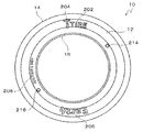
- FIG. 1 is a side view of a vehicle tire 10 according to an embodiment.
- the vehicle tire 10 includes a tread portion 14 having a tread surface that contacts a road surface, a bead portion 16 that is engaged with a wheel (not shown), and a sidewall portion 12 that connects the tread portion 14 and the bead portion 16 to form a tire side surface. It is comprised including.
- the sidewall portion 12 emphasizes resistance to deformation caused by a load during traveling, and the composition thereof is also different from that of the tread portion 14. More specifically, in the present embodiment, the sidewall portion 12 contains a diene rubber, carbon black, and silica, and the diene rubber contains 30 to 70% by mass of natural rubber and / or isoprene rubber.
- the carbon black has a nitrogen adsorption specific surface area of 20 to 60 m 2 / g, the carbon black content is 5 to 45 parts by mass with respect to 100 parts by mass of the diene rubber, and the silica content is diene type.
- the total content of carbon black and silica is 30 to 60 parts by mass with respect to 100 parts by mass of the diene rubber.
- various information is displayed on the sidewall portion 12.
- Examples of information displayed on the sidewall portion 12 include, for example, a manufacturer name 202 for manufacturing the vehicle tire 10, a manufacturer logo mark 204, a tire brand name 206, a tire dimension 208, a uniformity mark 214, a light spot mark. 216 or the like.
- the production number of the tire and the display of the rotation direction are also described.
- the uniformity mark 214 and the light spot mark 216 are attached using ink or the like after inspecting each tire after completion of the tire (after vulcanization).
- the manufacturer name 202, the manufacturer's logo mark 204, the tire brand name 206, the tire size 208, and the like indicate unevenness formed on the mold (mold) when the vehicle tire 10 is vulcanized. It is attached by transcription.
- the information other than the logo mark 204 is the same color as the entire vehicle tire 10, and each information can be visually recognized by the unevenness on the surface of the sidewall portion 12.
- the logo mark 204 is formed so as to be visually recognized in a color different from the color of the vehicle tire 10 such as a corporate color of a manufacturer.
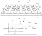
- FIG. 2 is an enlarged view of the logo mark 204 portion
- FIG. 2A is a perspective view
- FIG. 2B is a cross-sectional view along AA.
- a fine concavo-convex structure 30 is provided in the entire area of the logo mark 204.
- the fine concavo-convex structure 30 is configured by arranging fine concavo-convex portions 34 on a tire surface 32 at a constant arrangement period.
- the region where the fine concavo-convex structure 30 is provided is visually recognized in a color different from other regions depending on the structural color.
- the fine irregularities are various conventionally known structures such as protrusions and holes used for obtaining a structural color, and in this embodiment, fine protrusions protruding from the tire surface 32 which is a curved surface (or a flat surface). It is.
- the arrangement period is a distance between the centers of adjacent fine protrusions in this embodiment, that is, a pitch.
- the pitch corresponds to the sum of the lengths of the protrusions and recesses along the rubber member (tire) surface, as indicated by the symbol L in FIG. 2B.
- the constant arrangement period is a variety of conventionally known periods (pitch) used to obtain a structural color, and may be a uniform value throughout the fine concavo-convex structure 30, and may be continuous or stepwise.
- the arrangement period or the uneven height of the fine uneven portions 34 is determined based on the wavelength of visible light corresponding to the color visually recognized as the structural color. That is, the wavelength corresponding to the color to be expressed as the structural color is selected from the wavelength band classified as visible light, and the specific dimension of the arrangement period or the uneven height of the fine uneven portions 34 is determined by the principle of the resonance grating. .
- the arrangement period or the uneven height of the fine uneven portions 34 is configured to be, for example, 650 nm or less. This is because, as a result of experiments by the inventors of the present application, a structural color was recognized in the range where the arrangement period or the uneven height of the fine uneven structure 30 was 650 nm or less.
- the fine uneven portion 34 is a cylinder extending in a direction perpendicular to the tire surface 32.
- the upper surface 3402 of the cylinder is a perfect circle, and its diameter R is approximately 5 ⁇ m.
- the distance S between adjacent cylinders is 1 ⁇ m, and the arrangement period L is approximately 6 ⁇ m.
- the ratio is shown in a ratio different from the actual dimension.
- the present inventors set the height (unevenness height) H of the fine unevenness 34 from the tire surface 32 while fixing the arrangement period of the fine unevenness 34 and the diameter of the cylindrical fine unevenness 34. Changed to create multiple rubber members. As a result, the following structural colors were visually recognized in descending order of the visible area.
- the plurality of colors are visually recognized because the structural colors differ depending on the observation angle.
- the arrangement period or the height of the unevenness of the fine uneven portions 34 information can be displayed in an arbitrary color on the rubber surface. For example, when the logo mark 204 portion is to be displayed in red, the height of the unevenness may be about 650 nm.
- the method for producing a rubber member described below includes a step of forming a mold having a fine pattern structure (step 1 and step 2: mold forming step), attaching an unvulcanized rubber to the mold, It is configured by vulcanizing and transferring the fine concavo-convex structure onto the rubber surface (step 3: transfer step).
- step 1 and step 2 mold forming step
- step 3 transfer step
- the color of the structural color to be formed on the rubber member is determined, and the fine uneven portion is based on the wavelength of visible light corresponding to the color (the color visually recognized as the structural color on the rubber member).
- the arrangement period or the uneven height is determined (an array period determining step or an uneven height determining step).
- Step 1 In order to form the fine concavo-convex structure 30 on the rubber surface, a mask having a pattern structure arranged at a constant period is formed (mask forming step). First, a chromium (Cr) film is formed to a thickness of about 80 nm on a mask forming substrate (silicon substrate) using a sputtering apparatus. Next, a positive electron beam resist is spin-coated on the chromium film (3 seconds at 300 rpm, and then 60 seconds at 4000 rpm).
- pre-baking is performed for 3 minutes on a hot plate at 150 ° C.
- exposure and patterning are performed on the substrate coated with the electron beam resist using an electron beam drawing apparatus, and development is performed by immersing in a developer for 60 seconds.
- the arrangement period of the fine irregularities is determined based on the wavelength of visible light corresponding to the color visually recognized as the structural color, that is, when the arrangement period of the fine irregularities is used as a parameter for determining the color of the structural color
- the arrangement period of the pattern structure at the time of patterning is determined based on the arrangement period determined in the arrangement period determination step.
- a mask photomask
- Step 2 A mask is placed on a substrate formed of a metal or a semiconductor material, and the substrate is etched (etching step).
- a single crystal silicon substrate is used as the substrate.
- the substrate is cleaned with ultrasonic waves in the order of acetone and methanol for 5 minutes, and a positive photoresist is spin-coated on the substrate (3 seconds at 300 rpm, and then 60 seconds at 5000 rpm).
- substrate can be improved.
- the substrate coated with the photoresist is exposed using the mask aligner and the photomask prepared in Step 1, and the exposed portion is immersed in a developing solution to elute the exposed portion to perform patterning.
- the substrate is etched using a dry etching apparatus (passivation gas: C 4 F 8 , 80 sccm, etching gas: SF 6 , 130 sccm, Bosch process) to produce a mold (silicon mold).
- a dry etching apparatus passivation gas: C 4 F 8 , 80 sccm, etching gas: SF 6 , 130 sccm, Bosch process
- step 1 and step 2 mold forming step
- the method for producing a rubber member according to the present invention is not limited thereto.
- Various conventionally known methods can be applied.
- Step 3 An unvulcanized rubber is attached to the etched substrate (mold), and the unvulcanized rubber is vulcanized to transfer the fine concavo-convex structure onto the rubber surface (transfer step).
- Unvulcanized rubber was placed on a silicon mold, softened at 80 ° C. for 10 minutes, pressed, and vulcanized at 160 ° C. for about 10 minutes. After vulcanization, it was peeled off from the silicon mold, and it was confirmed that the fine uneven structure was transferred to the rubber surface. The region where the fine concavo-convex structure was formed was visually recognized with a color different from other regions (flat surface regions) on the rubber surface, that is, the structural color due to the fine concavo-convex structure.
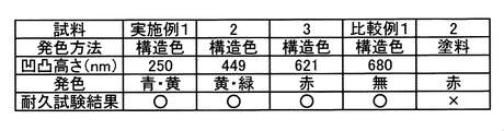
- FIG. 3 shows the endurance test results.
- the sample number, the coloring method, the unevenness height, the visually recognized color (coloring), and the durability test result are shown in order from the top.
- the surface state and the color were not changed, and the case where the color drop was observed was indicated as x.
- Comparative Example 2 the logo mark formed by printing with an inkjet printer (Comparative Example 2) became invisible after the ink was peeled off after the durability test, but the logo mark formed in a structural color (Examples 1 to 3).
- Comparative Example 1 there was no change in the visible state even after the durability test.
- Comparative Example 1 had a concavo-convex height of 680 nm, and was outside the range (650 nm or less) in which the above-described structural color was generated.
- the vehicle tire 10 displays at least a part of the rubber member in a color different from other regions by the structural color, so that the surface of the rubber is more than drawn using ink or the like. This is advantageous in improving the durability of the display.
- by appropriately changing the arrangement period or the uneven height of the fine uneven portions 34 it is possible to display the surface of the rubber member with an arbitrary color.
- the shape of the fine concavo-convex portion 34 is a cylindrical protrusion.
- the present invention is not limited to this, and various conventionally known shapes known as structures for displaying structural colors can be applied.
- the shape of the fine uneven portion 34 may be a conical protrusion or a lattice-shaped protrusion.
- the fine concavo-convex structure 30 may be a hole or a lattice-shaped groove formed on the rubber surface.
- the shape of the hole may be, for example, a cylindrical shape or a conical shape, and furthermore, fine particles or the like may be arranged at the bottom of the conical hole (the apex of the cone).
- the present invention is not limited to this, and various conventionally known rubber members, particularly members that vulcanize in the manufacturing process. Is suitable.
- only the logo mark 204 is displayed in the structural color.
- the present invention is not limited to this, and other information displayed on the sidewall portion 12 of the vehicle tire 10 is also displayed in the structural color. You may make it do.
- the fine uneven structure 30 may be formed in the whole rubber member, and the whole rubber member may be visually recognized with a structural color.
- the present invention is applied to information displayed on the sidewall portion 12 of the vehicle tire 10.
- the present invention is not limited to this, and the present invention is applied to information displayed at other locations of the vehicle tire 10. May be applied.
Landscapes
- Chemical & Material Sciences (AREA)
- Engineering & Computer Science (AREA)
- Mechanical Engineering (AREA)
- Health & Medical Sciences (AREA)
- Chemical Kinetics & Catalysis (AREA)
- Medicinal Chemistry (AREA)
- Polymers & Plastics (AREA)
- Organic Chemistry (AREA)
- Tires In General (AREA)
- Tyre Moulding (AREA)
- Shaping Of Tube Ends By Bending Or Straightening (AREA)
Abstract
ゴム部材の一例である車両用タイヤ10は、その表面の少なくとも一部に、型からの転写により形成され、微細凹凸部34が一定の配列周期で配列された微細凹凸構造30を有し、微細凹凸構造30が設けられた領域が、構造色により他の領域と異なる色で視認される。微細凹凸構造30は車両用タイヤ10のサイドウォール部12に形成されており、微細凹凸構造30が設けられた領域は、ロゴマーク204等の情報を示す形状で形成されている。これにより、ゴム部材の表面に長期に渡って視認可能な情報を付加することができる。
Description
本発明は、構造色により発色する領域を有するゴム部材、タイヤおよびゴム部材の製造方法に関する。
従来、タイヤをはじめとしたゴム製品の表面に文字やマーク等の情報を付加する場合、インクジェットプリンタ等でゴム表面にインクを付着させて印刷を行っている。
一方で、光の波長またはそれ以下の寸法の微細構造により発色が生じる構造色が知られており、各種の分野へと応用されている。
例えば、下記特許文献1には、構造色による発色を用いたカラーフィルタが開示されている。また、下記特許文献2には、構造色の発色の変化(波長変化)を測定することにより物体の歪を算出する技術が開示されている。特許文献1では、構造色を発生させる微細構造を型押しにより形成しており、特許文献2では、弾性体材料表面に微粒子を周期的に配列することにより構造色を発生させている。
一方で、光の波長またはそれ以下の寸法の微細構造により発色が生じる構造色が知られており、各種の分野へと応用されている。
例えば、下記特許文献1には、構造色による発色を用いたカラーフィルタが開示されている。また、下記特許文献2には、構造色の発色の変化(波長変化)を測定することにより物体の歪を算出する技術が開示されている。特許文献1では、構造色を発生させる微細構造を型押しにより形成しており、特許文献2では、弾性体材料表面に微粒子を周期的に配列することにより構造色を発生させている。
上述した従来技術のように、インクジェットプリンタによりタイヤに印刷を行った場合、走行中のゴムの伸縮(たわみ)によりゴム表面からインクが剥がれていくため、印刷した情報を長期間に渡って視認可能とするのが困難である。
また、上述のように構造色は各種の分野に応用されているが、特許文献1にように構造色を発生させる微細構造を型押しにより形成する方法や、複数の層を積層して構造色を発色させる方法などは、カラーフィルタ等の薄膜構造を有する製品に適用されており、またそのほとんどが透過光(回折光)に構造色を発生させるものであり、タイヤ等の透明度の低いゴム部材にそのまま適用することはできない。
また、特許文献2のように微粒子の配列により構造色を発生させる方法は、タイヤ製造時の加硫処理のように部材の変形を伴う加熱処理を行う必要がある部材には適用が困難である。
本発明は、このような事情に鑑みなされたものであり、その目的は、ゴム部材の表面に長期に渡って視認可能な情報を付加することにある。
また、上述のように構造色は各種の分野に応用されているが、特許文献1にように構造色を発生させる微細構造を型押しにより形成する方法や、複数の層を積層して構造色を発色させる方法などは、カラーフィルタ等の薄膜構造を有する製品に適用されており、またそのほとんどが透過光(回折光)に構造色を発生させるものであり、タイヤ等の透明度の低いゴム部材にそのまま適用することはできない。
また、特許文献2のように微粒子の配列により構造色を発生させる方法は、タイヤ製造時の加硫処理のように部材の変形を伴う加熱処理を行う必要がある部材には適用が困難である。
本発明は、このような事情に鑑みなされたものであり、その目的は、ゴム部材の表面に長期に渡って視認可能な情報を付加することにある。
上述の目的を達成するため、請求項1の発明にかかるゴム部材は、表面の少なくとも一部に、型からの転写により形成され、微細凹凸部が一定の配列周期で配列された微細凹凸構造を有し、前記微細凹凸構造が設けられた領域が、構造色により他の領域と異なる色で視認される、ことを特徴とする。
請求項2の発明にかかるゴム部材は、前記微細凹凸部の前記配列周期または凹凸高さが、前記構造色として視認される色に対応する可視光の波長に基づいて決定される、ことを特徴とする。
請求項3の発明にかかるゴム部材は、前記微細凹凸部の前記配列周期または凹凸高さは、650nm以下である、ことを特徴とする。
請求項4の発明にかかるタイヤは、請求項1から3のいずれか1項に記載のゴム部材で形成されている、ことを特徴とするタイヤ。
請求項5の発明にかかるタイヤは、前記微細凹凸構造がサイドウォール部に形成されており、前記微細凹凸構造が設けられた領域は、所定の情報を示す形状で形成されている、ことを特徴とする。
請求項6の発明にかかるタイヤは、前記サイドウォール部が、ジエン系ゴムと、カーボンブラックと、シリカとを含有し、前記ジエン系ゴムは30~70質量%の天然ゴムおよび/またはイソプレンゴムを含有し、前記カーボンブラックの窒素吸着比表面積は20~60m2/gであり、前記カーボンブラックの含有量は前記ジエン系ゴム100質量部に対して5~45質量部であり、前記シリカの含有量は前記ジエン系ゴム100質量部に対して15~55質量部であり、前記カーボンブラックと前記シリカとの合計含有量は前記ジエン系ゴム100質量部に対して30~60質量部である、ことを特徴とする。
請求項7の発明にかかるゴム部材の製造方法は、請求項1から3のいずれか1項に記載のゴム部材の製造方法であって、前記一定周期でパターン構造が配置されたマスクを形成するマスク形成工程と、前記マスクを金属または半導体材料で形成された基板上に配置し、前記基板をエッチングするエッチング工程と、前記基板に未加硫ゴムを着接し、前記未加硫ゴムを加硫してゴム表面に前記微細凹凸構造を転写する転写工程と、を含むことを特徴とする。
請求項8の発明にかかるゴム部材の製造方法は、前記構造色として視認される色に対応する可視光の波長に基づいて前記微細凹凸部の前記配列周期を決定する配列周期決定工程を更に備え、前記マスク形成工程では、前記パターン構造の周期を前記配列周期決定工程で決定した前記配列周期に基づいて決定する、ことを特徴とする。
請求項9の発明にかかるゴム部材の製造方法は、前記構造色として視認される色に対応する可視光の波長に基づいて前記微細凹凸部の前記凹凸高さを決定する凹凸高さ決定工程を更に備え、前記エッチング工程では、前記基板のエッチング時間を制御することにより前記微小凹凸部の前記凹凸高さを前記凹凸高さ決定工程で決定した前記凹凸高さと一致させる、ことを特徴とする。
請求項2の発明にかかるゴム部材は、前記微細凹凸部の前記配列周期または凹凸高さが、前記構造色として視認される色に対応する可視光の波長に基づいて決定される、ことを特徴とする。
請求項3の発明にかかるゴム部材は、前記微細凹凸部の前記配列周期または凹凸高さは、650nm以下である、ことを特徴とする。
請求項4の発明にかかるタイヤは、請求項1から3のいずれか1項に記載のゴム部材で形成されている、ことを特徴とするタイヤ。
請求項5の発明にかかるタイヤは、前記微細凹凸構造がサイドウォール部に形成されており、前記微細凹凸構造が設けられた領域は、所定の情報を示す形状で形成されている、ことを特徴とする。
請求項6の発明にかかるタイヤは、前記サイドウォール部が、ジエン系ゴムと、カーボンブラックと、シリカとを含有し、前記ジエン系ゴムは30~70質量%の天然ゴムおよび/またはイソプレンゴムを含有し、前記カーボンブラックの窒素吸着比表面積は20~60m2/gであり、前記カーボンブラックの含有量は前記ジエン系ゴム100質量部に対して5~45質量部であり、前記シリカの含有量は前記ジエン系ゴム100質量部に対して15~55質量部であり、前記カーボンブラックと前記シリカとの合計含有量は前記ジエン系ゴム100質量部に対して30~60質量部である、ことを特徴とする。
請求項7の発明にかかるゴム部材の製造方法は、請求項1から3のいずれか1項に記載のゴム部材の製造方法であって、前記一定周期でパターン構造が配置されたマスクを形成するマスク形成工程と、前記マスクを金属または半導体材料で形成された基板上に配置し、前記基板をエッチングするエッチング工程と、前記基板に未加硫ゴムを着接し、前記未加硫ゴムを加硫してゴム表面に前記微細凹凸構造を転写する転写工程と、を含むことを特徴とする。
請求項8の発明にかかるゴム部材の製造方法は、前記構造色として視認される色に対応する可視光の波長に基づいて前記微細凹凸部の前記配列周期を決定する配列周期決定工程を更に備え、前記マスク形成工程では、前記パターン構造の周期を前記配列周期決定工程で決定した前記配列周期に基づいて決定する、ことを特徴とする。
請求項9の発明にかかるゴム部材の製造方法は、前記構造色として視認される色に対応する可視光の波長に基づいて前記微細凹凸部の前記凹凸高さを決定する凹凸高さ決定工程を更に備え、前記エッチング工程では、前記基板のエッチング時間を制御することにより前記微小凹凸部の前記凹凸高さを前記凹凸高さ決定工程で決定した前記凹凸高さと一致させる、ことを特徴とする。
請求項1の発明によれば、ゴム部材の少なくとも一部を構造色により他の領域と異なる色で表示するので、インクなどを用いて描画するよりも、ゴム表面の表示の耐久性を向上させる上で有利となる。
請求項2の発明によれば、微細凹凸部の配列周期または凹凸高さを適宜変更することにより、ゴム部材の表面に任意の色で表示を行うことができる。
請求項3の発明によれば、赤色をはじめとする任意の色で表示を行うことができる。
請求項4の発明によれば、タイヤ表面に構造色により情報を表示することができ、タイヤの使用に伴う摩耗に対して高い耐久性を有する表示を行う上で有利となる。
請求項5の発明によれば、タイヤのうち周辺から視認しやすく、また従来よりタイヤに関する各種の情報が表示されているサイドウォール部に、構造色を用いた耐久性の高い表示を行う上で有利となる。
請求項6の発明によれば、サイドウォール部に適した耐変形性の高い組成のゴム表面に構造色による表示を形成する上で有利となる。
請求項7の発明によれば、ゴム部材の少なくとも一部に構造色により他の領域と異なる色で表示する領域を形成できるので、インクなどを用いて描画するよりも、ゴム表面の表示の耐久性を向上させる上で有利となる。
請求項8の発明によれば、微小凹凸部の配列周期を任意の寸法に形成する上で有利となる。
請求項9の発明によれば、微小凹凸部の凹凸高さを任意の寸法に形成する上で有利となる。
請求項2の発明によれば、微細凹凸部の配列周期または凹凸高さを適宜変更することにより、ゴム部材の表面に任意の色で表示を行うことができる。
請求項3の発明によれば、赤色をはじめとする任意の色で表示を行うことができる。
請求項4の発明によれば、タイヤ表面に構造色により情報を表示することができ、タイヤの使用に伴う摩耗に対して高い耐久性を有する表示を行う上で有利となる。
請求項5の発明によれば、タイヤのうち周辺から視認しやすく、また従来よりタイヤに関する各種の情報が表示されているサイドウォール部に、構造色を用いた耐久性の高い表示を行う上で有利となる。
請求項6の発明によれば、サイドウォール部に適した耐変形性の高い組成のゴム表面に構造色による表示を形成する上で有利となる。
請求項7の発明によれば、ゴム部材の少なくとも一部に構造色により他の領域と異なる色で表示する領域を形成できるので、インクなどを用いて描画するよりも、ゴム表面の表示の耐久性を向上させる上で有利となる。
請求項8の発明によれば、微小凹凸部の配列周期を任意の寸法に形成する上で有利となる。
請求項9の発明によれば、微小凹凸部の凹凸高さを任意の寸法に形成する上で有利となる。
以下に添付図面を参照して、本発明に係るゴム部材、タイヤおよびゴム部材の製造方法の好適な実施の形態を詳細に説明する。
本実施の形態では、本発明に係るゴム部材を車両用タイヤに適用した例について説明する。
図1は、実施の形態にかかる車両用タイヤ10の側面図である。
車両用タイヤ10は、路面へ接地するトレッド面を有するトレッド部14、図示しないホイールと係合されるビード部16、それらトレッド部14とビード部16とを接続しタイヤ側面となるサイドウォール部12を含んで構成される。
トレッド部14が耐摩耗性を重視されるのに対して、サイドウォール部12は走行中の荷重による変形に耐えることが重視されており、その組成もトレッド部14とは異なっている。
より詳細には、本実施の形態では、サイドウォール部12は、ジエン系ゴムと、カーボンブラックと、シリカとを含有し、ジエン系ゴムは30~70質量%の天然ゴムおよび/またはイソプレンゴムを含有し、カーボンブラックの窒素吸着比表面積は20~60m2/gであり、カーボンブラックの含有量はジエン系ゴム100質量部に対して5~45質量部であり、シリカの含有量はジエン系ゴム100質量部に対して15~55質量部であり、カーボンブラックとシリカとの合計含有量はジエン系ゴム100質量部に対して30~60質量部となっている。
本実施の形態では、本発明に係るゴム部材を車両用タイヤに適用した例について説明する。
図1は、実施の形態にかかる車両用タイヤ10の側面図である。
車両用タイヤ10は、路面へ接地するトレッド面を有するトレッド部14、図示しないホイールと係合されるビード部16、それらトレッド部14とビード部16とを接続しタイヤ側面となるサイドウォール部12を含んで構成される。
トレッド部14が耐摩耗性を重視されるのに対して、サイドウォール部12は走行中の荷重による変形に耐えることが重視されており、その組成もトレッド部14とは異なっている。
より詳細には、本実施の形態では、サイドウォール部12は、ジエン系ゴムと、カーボンブラックと、シリカとを含有し、ジエン系ゴムは30~70質量%の天然ゴムおよび/またはイソプレンゴムを含有し、カーボンブラックの窒素吸着比表面積は20~60m2/gであり、カーボンブラックの含有量はジエン系ゴム100質量部に対して5~45質量部であり、シリカの含有量はジエン系ゴム100質量部に対して15~55質量部であり、カーボンブラックとシリカとの合計含有量はジエン系ゴム100質量部に対して30~60質量部となっている。
また、サイドウォール部12には、各種の情報が表示されている。
サイドウォール部12に表示される情報の一例としては、例えば車両用タイヤ10を製造するメーカー名202、メーカーのロゴマーク204、タイヤのブランド名206、タイヤの寸法208、ユニフォミティマーク214、軽点マーク216などが挙げられる。また、この他タイヤの製造番号や回転方向表示なども記載される。
サイドウォール部12に表示される情報の一例としては、例えば車両用タイヤ10を製造するメーカー名202、メーカーのロゴマーク204、タイヤのブランド名206、タイヤの寸法208、ユニフォミティマーク214、軽点マーク216などが挙げられる。また、この他タイヤの製造番号や回転方向表示なども記載される。
このうち、ユニフォミティマーク214および軽点マーク216は、タイヤの完成後(加硫後)、個々のタイヤを検査した上でインク等を用いて付される。
また、メーカー名202、メーカーのロゴマーク204、タイヤのブランド名206、タイヤの寸法208等は、車両用タイヤ10を加硫する際の金型(モールド)に形成された凹凸を、加硫時に転写することによって付される。
これら金型の凹凸によって転写される情報のうち、ロゴマーク204以外は車両用タイヤ10全体と同色であり、サイドウォール部12の表面に対する凹凸によって各情報を視認可能となっている。
一方、ロゴマーク204は、例えばメーカーのコーポレートカラー等、車両用タイヤ10の色とは異なる色で視認されるように形成されている。
また、メーカー名202、メーカーのロゴマーク204、タイヤのブランド名206、タイヤの寸法208等は、車両用タイヤ10を加硫する際の金型(モールド)に形成された凹凸を、加硫時に転写することによって付される。
これら金型の凹凸によって転写される情報のうち、ロゴマーク204以外は車両用タイヤ10全体と同色であり、サイドウォール部12の表面に対する凹凸によって各情報を視認可能となっている。
一方、ロゴマーク204は、例えばメーカーのコーポレートカラー等、車両用タイヤ10の色とは異なる色で視認されるように形成されている。
図2は、ロゴマーク204部分の拡大図であり、図2Aは斜視図、図2BはA-A断面図である。
ロゴマーク204の全域には微細凹凸構造30が設けられている。
微細凹凸構造30は、タイヤ表面32に微細凹凸部34が一定の配列周期で配列されて構成されている。この微細凹凸構造30が設けられた領域が、構造色により他の領域と異なる色で視認される。
ここで微細凹凸部とは、構造色を得るために用いられる突起や孔など従来公知の様々な構造であり、本実施の形態では曲面(あるいは平面)であるタイヤ表面32から突出する微細な突起である。
また、配列周期とは、本実施の形態では隣り合う微細な突起の中心間の距離、すなわちピッチである。ピッチは、図2Bの符号Lに示すように、ゴム部材(タイヤ)表面に沿った突起と凹部との長さの合計と一致する。
また、一定の配列周期とは、構造色を得るために用いられる従来公知の様々な周期(ピッチ)であり、微細凹凸構造30の全体において均一の値の場合もあり、連続的にあるいは段階的に変化させる場合もある。
微細凹凸部34の配列周期または凹凸高さは、構造色として視認される色に対応する可視光の波長に基づいて決定される。すなわち、可視光に分類される波長帯から、構造色として表現したい色に対応する波長を選択し、共鳴格子の原理により微細凹凸部34の配列周期または凹凸高さの具体的な寸法を決定する。
本実施の形態では、微細凹凸部34の配列周期または凹凸高さは、例えば650nm以下で構成される。これは、本願発明者らの実験の結果、微細凹凸構造30の配列周期または凹凸高さが650nm以下の範囲で構造色が認められたためである。
ロゴマーク204の全域には微細凹凸構造30が設けられている。
微細凹凸構造30は、タイヤ表面32に微細凹凸部34が一定の配列周期で配列されて構成されている。この微細凹凸構造30が設けられた領域が、構造色により他の領域と異なる色で視認される。
ここで微細凹凸部とは、構造色を得るために用いられる突起や孔など従来公知の様々な構造であり、本実施の形態では曲面(あるいは平面)であるタイヤ表面32から突出する微細な突起である。
また、配列周期とは、本実施の形態では隣り合う微細な突起の中心間の距離、すなわちピッチである。ピッチは、図2Bの符号Lに示すように、ゴム部材(タイヤ)表面に沿った突起と凹部との長さの合計と一致する。
また、一定の配列周期とは、構造色を得るために用いられる従来公知の様々な周期(ピッチ)であり、微細凹凸構造30の全体において均一の値の場合もあり、連続的にあるいは段階的に変化させる場合もある。
微細凹凸部34の配列周期または凹凸高さは、構造色として視認される色に対応する可視光の波長に基づいて決定される。すなわち、可視光に分類される波長帯から、構造色として表現したい色に対応する波長を選択し、共鳴格子の原理により微細凹凸部34の配列周期または凹凸高さの具体的な寸法を決定する。
本実施の形態では、微細凹凸部34の配列周期または凹凸高さは、例えば650nm以下で構成される。これは、本願発明者らの実験の結果、微細凹凸構造30の配列周期または凹凸高さが650nm以下の範囲で構造色が認められたためである。
本実施の形態では、微細凹凸部34はタイヤ表面32に対して直交する方向に延びる円柱である。円柱の上面3402は正円形であり、その直径Rはおよそ5μmである。また、隣り合う円柱間の距離Sは1μmであり、配列周期Lはおよそ6μmである。なお、図2では図示の便宜上、実際の寸法とは異なる比率で図示している。
ここで、本願発明者らは、微細凹凸部34の配列周期や円柱状の微細凹凸部34の直径は固定したまま、微細凹凸部34のタイヤ表面32からの高さ(凹凸高さ)Hを変更して複数のゴム部材を作成した。その結果、視認される面積が大きい順に以下のような構造色が視認された。複数の色が視認されるのは、構造色は観察角度によって色が異なるためである。
凹凸高さ650nm:赤、赤紫
凹凸高さ607nm:赤紫、赤、橙
凹凸高さ577nm:赤紫、橙
凹凸高さ536nm:橙、赤紫
凹凸高さ500nm:黄、緑、橙
以下、凹凸高さを小さくするほど青みが強くなる傾向にあった。
このように、微細凹凸部34の配列周期または凹凸高さを調整することにより、ゴム表面に任意の色で情報を表示することができる。例えばロゴマーク204部分を赤色で表示したい場合、凹凸高さを650nm程度にすればよい。
ここで、本願発明者らは、微細凹凸部34の配列周期や円柱状の微細凹凸部34の直径は固定したまま、微細凹凸部34のタイヤ表面32からの高さ(凹凸高さ)Hを変更して複数のゴム部材を作成した。その結果、視認される面積が大きい順に以下のような構造色が視認された。複数の色が視認されるのは、構造色は観察角度によって色が異なるためである。
凹凸高さ650nm:赤、赤紫
凹凸高さ607nm:赤紫、赤、橙
凹凸高さ577nm:赤紫、橙
凹凸高さ536nm:橙、赤紫
凹凸高さ500nm:黄、緑、橙
以下、凹凸高さを小さくするほど青みが強くなる傾向にあった。
このように、微細凹凸部34の配列周期または凹凸高さを調整することにより、ゴム表面に任意の色で情報を表示することができる。例えばロゴマーク204部分を赤色で表示したい場合、凹凸高さを650nm程度にすればよい。
つぎに、構造色を有するゴム部材の製造方法について説明する。
以下に説明するゴム部材の製造方法は、微細なパターン構造を有する鋳型を形成する工程(工程1および工程2:鋳型形成工程)と、鋳型に未加硫ゴムを着接し、未加硫ゴムを加硫してゴム表面に微細凹凸構造を転写する(工程3:転写工程)とによって構成される。
なお、以下の工程に先立って、ゴム部材上に形成したい構造色の色を決め、当該色(ゴム部材上で構造色として視認される色)に対応する可視光の波長に基づいて微細凹凸部記配列周期または凹凸高さを決定しておく(配列周期決定工程または凹凸高さ決定工程)。
以下に説明するゴム部材の製造方法は、微細なパターン構造を有する鋳型を形成する工程(工程1および工程2:鋳型形成工程)と、鋳型に未加硫ゴムを着接し、未加硫ゴムを加硫してゴム表面に微細凹凸構造を転写する(工程3:転写工程)とによって構成される。
なお、以下の工程に先立って、ゴム部材上に形成したい構造色の色を決め、当該色(ゴム部材上で構造色として視認される色)に対応する可視光の波長に基づいて微細凹凸部記配列周期または凹凸高さを決定しておく(配列周期決定工程または凹凸高さ決定工程)。
(工程1)ゴム表面に微細凹凸構造30を形成するため、一定周期でパターン構造が配置されたマスクを形成する(マスク形成工程)。
まず、マスク形成用基板(シリコン基板)にスパッタリング装置を用いてクロム(Cr)を約80nm成膜する。つぎに、クロム膜上にポジ型電子線レジストをスピンコート(300rpmで3秒、のち4000rpmで60秒)する。その後、150℃のホットプレートで3分間プリベークを行い、電子線レジストをコートした基板に電子線描画装置を用いて露光、パターニング後、現像液に60秒浸漬して現像を行う。なお、構造色として視認される色に対応する可視光の波長に基づいて微細凹凸部の配列周期を決定した場合、つまり構造色の発色を決めるパラメータとして微細凹凸部の配列周期を用いた場合、パターニング時のパターン構造の配列周期を配列周期決定工程で決定した配列周期に基づいて決定する。現像後、混酸クロムエッチング液に約60秒浸し、露出しているCrのみを選択的に溶かすことでマスク(フォトマスク)を作製した。
まず、マスク形成用基板(シリコン基板)にスパッタリング装置を用いてクロム(Cr)を約80nm成膜する。つぎに、クロム膜上にポジ型電子線レジストをスピンコート(300rpmで3秒、のち4000rpmで60秒)する。その後、150℃のホットプレートで3分間プリベークを行い、電子線レジストをコートした基板に電子線描画装置を用いて露光、パターニング後、現像液に60秒浸漬して現像を行う。なお、構造色として視認される色に対応する可視光の波長に基づいて微細凹凸部の配列周期を決定した場合、つまり構造色の発色を決めるパラメータとして微細凹凸部の配列周期を用いた場合、パターニング時のパターン構造の配列周期を配列周期決定工程で決定した配列周期に基づいて決定する。現像後、混酸クロムエッチング液に約60秒浸し、露出しているCrのみを選択的に溶かすことでマスク(フォトマスク)を作製した。
(工程2)マスクを金属または半導体材料で形成された基板上に配置し、基板をエッチングする(エッチング工程)。
本実施の形態では、上記基板として単結晶シリコン基板を使用する。この基板をアセトン、メタノールの順に5分間超音波で洗浄し、基板上にポジ型フォトレジストをスピンコート(300rpmで3秒、のち5000rpmで60秒)する。つぎに、95℃のホットプレートで90秒プリベークする。これにより、レジストに含まれる有機溶剤を蒸発させて基板との密着性を向上させることができる。つづいて、フォトレジストをコートした基板にマスクアライナーと工程1で作製したフォトマスクを用いて露光を行い、現像液に浸すことで露光した箇所を溶出させてパターニングを行う。
パターニング後、ドライエッチング装置(パッシベーションガス:C4F8,80sccm,エッチングガス:SF6,130sccm,ボッシュプロセス)を用いて、基板のエッチングを行い、鋳型(シリコン鋳型)を作製する。なお、構造色として視認される色に対応する可視光の波長に基づいて微細凹凸部の凹凸高さを決定した場合、つまり構造色の発色を決めるパラメータとして微細凹凸部の凹凸高さを用いた場合、基板のエッチング時間を適宜制御することにより、微小凹凸部の凹凸高さを凹凸高さ決定工程で決定した凹凸高さと一致させることができる。
また、上記工程1および工程2(鋳型形成工程)では、フォトリソグラフィ技術を用いて微細凹凸構造を有する鋳型を作製する場合について説明したが、本発明にかかるゴム部材の製造方法はこれに限らず、従来公知の様々な手法を適用可能である。
本実施の形態では、上記基板として単結晶シリコン基板を使用する。この基板をアセトン、メタノールの順に5分間超音波で洗浄し、基板上にポジ型フォトレジストをスピンコート(300rpmで3秒、のち5000rpmで60秒)する。つぎに、95℃のホットプレートで90秒プリベークする。これにより、レジストに含まれる有機溶剤を蒸発させて基板との密着性を向上させることができる。つづいて、フォトレジストをコートした基板にマスクアライナーと工程1で作製したフォトマスクを用いて露光を行い、現像液に浸すことで露光した箇所を溶出させてパターニングを行う。
パターニング後、ドライエッチング装置(パッシベーションガス:C4F8,80sccm,エッチングガス:SF6,130sccm,ボッシュプロセス)を用いて、基板のエッチングを行い、鋳型(シリコン鋳型)を作製する。なお、構造色として視認される色に対応する可視光の波長に基づいて微細凹凸部の凹凸高さを決定した場合、つまり構造色の発色を決めるパラメータとして微細凹凸部の凹凸高さを用いた場合、基板のエッチング時間を適宜制御することにより、微小凹凸部の凹凸高さを凹凸高さ決定工程で決定した凹凸高さと一致させることができる。
また、上記工程1および工程2(鋳型形成工程)では、フォトリソグラフィ技術を用いて微細凹凸構造を有する鋳型を作製する場合について説明したが、本発明にかかるゴム部材の製造方法はこれに限らず、従来公知の様々な手法を適用可能である。
(工程3)エッチングした基板(鋳型)に未加硫ゴムを着接し、未加硫ゴムを加硫してゴム表面に微細凹凸構造を転写する(転写工程)。
シリコン鋳型に未加硫のゴムを載せ、80℃で10分間軟化させた後にプレスし、160℃で10分程度加硫した。
加硫後、シリコン鋳型から剥がしとり、ゴム表面に微細凹凸構造が転写されていることを確認した。微細凹凸構造が形成されている領域は、ゴム表面上の他の領域(平坦面領域)とは異なる色、すなわち微細凹凸構造による構造色で視認された。
シリコン鋳型に未加硫のゴムを載せ、80℃で10分間軟化させた後にプレスし、160℃で10分程度加硫した。
加硫後、シリコン鋳型から剥がしとり、ゴム表面に微細凹凸構造が転写されていることを確認した。微細凹凸構造が形成されている領域は、ゴム表面上の他の領域(平坦面領域)とは異なる色、すなわち微細凹凸構造による構造色で視認された。
このように構造色で形成したロゴマーク204と、従来技術のようにインクジェットプリンタによる印字で形成したロゴマークとの耐久試験を実施した。具体的には、それぞれの方法で形成したロゴマーク表面(ゴム表面)を綿布で100回こすり、その表面状態および色の変化を目視観察した。
図3に耐久試験結果を示す。図3の表には、上から順に試料番号、発色方法、凹凸高さ、視認される色(発色)、および耐久試験結果を示した。耐久試験結果の欄では、表面状態および色が、共に変化がないものを○、色の脱落が観察されたものを×と表記した。
図3に示すように、インクジェットプリンタによる印字で形成したロゴマーク(比較例2)は耐久試験後にはインクが剥離して視認できなくなったが、構造色で形成したロゴマーク(実施例1~3および比較例1)は耐久試験後にも視認状態に変化がなかった。
なお、構造色で形成したロゴマークのうち比較例1は、その凹凸高さが680nmであり、上述した構造色を発生する範囲(650nm以下)を外れているため、発色は認められなかった。
図3に耐久試験結果を示す。図3の表には、上から順に試料番号、発色方法、凹凸高さ、視認される色(発色)、および耐久試験結果を示した。耐久試験結果の欄では、表面状態および色が、共に変化がないものを○、色の脱落が観察されたものを×と表記した。
図3に示すように、インクジェットプリンタによる印字で形成したロゴマーク(比較例2)は耐久試験後にはインクが剥離して視認できなくなったが、構造色で形成したロゴマーク(実施例1~3および比較例1)は耐久試験後にも視認状態に変化がなかった。
なお、構造色で形成したロゴマークのうち比較例1は、その凹凸高さが680nmであり、上述した構造色を発生する範囲(650nm以下)を外れているため、発色は認められなかった。
以上説明したように、実施の形態にかかる車両用タイヤ10は、ゴム部材の少なくとも一部を構造色により他の領域と異なる色で表示するので、インクなどを用いて描画するよりも、ゴム表面の表示の耐久性を向上させる上で有利となる。
また、微細凹凸部34の配列周期または凹凸高さを適宜変更することにより、ゴム部材の表面に任意の色で表示を行うことができる。
また、微細凹凸部34の配列周期または凹凸高さを適宜変更することにより、ゴム部材の表面に任意の色で表示を行うことができる。
なお、本実施の形態では、微細凹凸部34の形状を円柱形の突起としたが、これに限らず、構造色を表示するための構造として知られる従来公知の様々な形状を適用可能である。例えば微細凹凸部34の形状を、円錐状の突起や格子状の突起としてもよい。また、微細凹凸構造30をゴム表面に形成された孔や格子状の溝としてもよい。この場合も、孔の形状は例えば円筒形や円錐形などであってもよく、さらには円錐形に形成した孔の底部(円錐の頂点)に微粒子等を配置してもよい。
また、本実施の形態では、本発明に係るゴム部材を車両用タイヤに適用した例について説明したが、これに限らず、従来公知の様々なゴム部材、特に製造工程で加硫を行う部材に適している。
また、本実施の形態では、ロゴマーク204のみを構造色で表示するものとしたが、これに限らず、車両用タイヤ10のサイドウォール部12に表示される他の情報についても構造色で表示するようにしてもよい。また、ゴム部材の全体に微細凹凸構造30を形成し、ゴム部材全体が構造色で視認されるようにしてもよい。
また、本実施の形態では、車両用タイヤ10のサイドウォール部12に表示される情報に本発明を適用したが、これに限らず車両用タイヤ10の他の箇所に表示される情報に本発明を適用してもよい。
また、本実施の形態では、本発明に係るゴム部材を車両用タイヤに適用した例について説明したが、これに限らず、従来公知の様々なゴム部材、特に製造工程で加硫を行う部材に適している。
また、本実施の形態では、ロゴマーク204のみを構造色で表示するものとしたが、これに限らず、車両用タイヤ10のサイドウォール部12に表示される他の情報についても構造色で表示するようにしてもよい。また、ゴム部材の全体に微細凹凸構造30を形成し、ゴム部材全体が構造色で視認されるようにしてもよい。
また、本実施の形態では、車両用タイヤ10のサイドウォール部12に表示される情報に本発明を適用したが、これに限らず車両用タイヤ10の他の箇所に表示される情報に本発明を適用してもよい。
10……車両用タイヤ、12……サイドウォール部、14……トレッド部、16……ビード部、30……微細凹凸構造、32……タイヤ表面、34……微細凹凸部、202……メーカー名、204……ロゴマーク、206……ブランド名、208……寸法、214……ユニフォミティマーク、216……軽点マーク。
Claims (9)
- 表面の少なくとも一部に、型からの転写により形成され、微細凹凸部が一定の配列周期で配列された微細凹凸構造を有し、
前記微細凹凸構造が設けられた領域が、構造色により他の領域と異なる色で視認される、
ことを特徴とするゴム部材。 - 前記微細凹凸部の前記配列周期または凹凸高さは、前記構造色として視認される色に対応する可視光の波長に基づいて決定される、
ことを特徴とする請求項1記載のゴム部材。 - 前記微細凹凸部の前記配列周期または凹凸高さは、650nm以下である、
ことを特徴とする請求項1または2記載のゴム部材。 - 請求項1から3のいずれか1項に記載のゴム部材で形成されたタイヤ。
- 前記微細凹凸構造がサイドウォール部に形成されており、
前記微細凹凸構造が設けられた領域は、所定の情報を示す形状で形成されている、
ことを特徴とする請求項4記載のタイヤ。 - 前記サイドウォール部は、ジエン系ゴムと、カーボンブラックと、シリカとを含有し、
前記ジエン系ゴムは30~70質量%の天然ゴムおよび/またはイソプレンゴムを含有し、前記カーボンブラックの窒素吸着比表面積は20~60m2/gであり、前記カーボンブラックの含有量は前記ジエン系ゴム100質量部に対して5~45質量部であり、前記シリカの含有量は前記ジエン系ゴム100質量部に対して15~55質量部であり、前記カーボンブラックと前記シリカとの合計含有量は前記ジエン系ゴム100質量部に対して30~60質量部である、
ことを特徴とする請求項5記載のタイヤ。 - 請求項1から3のいずれか1項に記載のゴム部材の製造方法であって、
前記一定周期でパターン構造が配置されたマスクを形成するマスク形成工程と、
前記マスクを金属または半導体材料で形成された基板上に配置し、前記基板をエッチングするエッチング工程と、
前記基板に未加硫ゴムを着接し、前記未加硫ゴムを加硫してゴム表面に前記微細凹凸構造を転写する転写工程と、
を含むことを特徴とするゴム部材の製造方法。 - 前記構造色として視認される色に対応する可視光の波長に基づいて前記微細凹凸部の前記配列周期を決定する配列周期決定工程を更に備え、
前記マスク形成工程では、前記パターン構造の周期を前記配列周期決定工程で決定した前記配列周期に基づいて決定する、
ことを特徴とする請求項7記載のゴム部材の製造方法。 - 前記構造色として視認される色に対応する可視光の波長に基づいて前記微細凹凸部の前記凹凸高さを決定する凹凸高さ決定工程を更に備え、
前記エッチング工程では、前記基板のエッチング時間を制御することにより前記微小凹凸部の前記凹凸高さを前記凹凸高さ決定工程で決定した前記凹凸高さと一致させる、
ことを特徴とする請求項7記載のゴム部材の製造方法。
Priority Applications (6)
| Application Number | Priority Date | Filing Date | Title |
|---|---|---|---|
| CN201780027258.2A CN109153168A (zh) | 2016-05-02 | 2017-05-02 | 橡胶构件、轮胎以及橡胶构件的制造方法 |
| JP2017538752A JP6302144B1 (ja) | 2016-05-02 | 2017-05-02 | ゴム部材、タイヤおよびゴム部材の製造方法 |
| US16/098,819 US20190202244A1 (en) | 2016-05-02 | 2017-05-02 | Rubber Member, Tire, and Method of Manufacturing Rubber Member |
| EP17792771.2A EP3453519B1 (en) | 2016-05-02 | 2017-05-02 | Rubber member and method of manufacturing rubber member |
| US17/374,854 US20210339575A1 (en) | 2016-05-02 | 2021-07-13 | Rubber Member, Tire, and Method of Manufacturing Rubber Member |
| US18/113,006 US12434513B2 (en) | 2016-05-02 | 2023-02-22 | Rubber member, tire, and method of manufacturing rubber member |
Applications Claiming Priority (2)
| Application Number | Priority Date | Filing Date | Title |
|---|---|---|---|
| JP2016-092388 | 2016-05-02 | ||
| JP2016092388 | 2016-05-02 |
Related Child Applications (2)
| Application Number | Title | Priority Date | Filing Date |
|---|---|---|---|
| US16/098,819 A-371-Of-International US20190202244A1 (en) | 2016-05-02 | 2017-05-02 | Rubber Member, Tire, and Method of Manufacturing Rubber Member |
| US17/374,854 Division US20210339575A1 (en) | 2016-05-02 | 2021-07-13 | Rubber Member, Tire, and Method of Manufacturing Rubber Member |
Publications (1)
| Publication Number | Publication Date |
|---|---|
| WO2017191839A1 true WO2017191839A1 (ja) | 2017-11-09 |
Family
ID=60203060
Family Applications (1)
| Application Number | Title | Priority Date | Filing Date |
|---|---|---|---|
| PCT/JP2017/017216 Ceased WO2017191839A1 (ja) | 2016-05-02 | 2017-05-02 | ゴム部材、タイヤおよびゴム部材の製造方法 |
Country Status (5)
| Country | Link |
|---|---|
| US (3) | US20190202244A1 (ja) |
| EP (1) | EP3453519B1 (ja) |
| JP (1) | JP6302144B1 (ja) |
| CN (1) | CN109153168A (ja) |
| WO (1) | WO2017191839A1 (ja) |
Cited By (2)
| Publication number | Priority date | Publication date | Assignee | Title |
|---|---|---|---|---|
| CN112789181A (zh) * | 2018-09-20 | 2021-05-11 | 横滨橡胶株式会社 | 充气轮胎 |
| US11584168B2 (en) * | 2019-09-30 | 2023-02-21 | Sumitomo Rubber Industries, Ltd. | Tire |
Families Citing this family (5)
| Publication number | Priority date | Publication date | Assignee | Title |
|---|---|---|---|---|
| JP7056231B2 (ja) * | 2018-02-28 | 2022-04-19 | 住友ゴム工業株式会社 | タイヤ |
| JP7000915B2 (ja) * | 2018-02-28 | 2022-01-19 | 住友ゴム工業株式会社 | タイヤ |
| JP7069828B2 (ja) * | 2018-02-28 | 2022-05-18 | 住友ゴム工業株式会社 | タイヤ |
| JP7052414B2 (ja) * | 2018-02-28 | 2022-04-12 | 住友ゴム工業株式会社 | タイヤ |
| CN116968479A (zh) * | 2022-04-23 | 2023-10-31 | 山东东岳科技发展有限公司 | 一种轮胎表面阵列微结构及其轮胎 |
Citations (5)
| Publication number | Priority date | Publication date | Assignee | Title |
|---|---|---|---|---|
| JPS4925025B1 (ja) | 1971-03-10 | 1974-06-27 | ||
| JPS63302031A (ja) * | 1987-06-02 | 1988-12-08 | Yokohama Rubber Co Ltd:The | タイヤサイド部への紋様刻印方法 |
| JP2009192676A (ja) | 2008-02-13 | 2009-08-27 | Bridgestone Corp | カラーフィルタの製造方法及びカラーフィルタ |
| JP2012250575A (ja) * | 2011-05-31 | 2012-12-20 | Bridgestone Corp | タイヤ |
| WO2017086363A1 (ja) * | 2015-11-16 | 2017-05-26 | 株式会社ブリヂストン | タイヤの製造方法 |
Family Cites Families (11)
| Publication number | Priority date | Publication date | Assignee | Title |
|---|---|---|---|---|
| JP3553890B2 (ja) * | 2000-01-27 | 2004-08-11 | 横浜ゴム株式会社 | タイヤ用ゴム組成物及びそれを用いるタイヤの製造方法 |
| JP3811045B2 (ja) * | 2001-03-27 | 2006-08-16 | 日本碍子株式会社 | サイプブレード成形用金型及びその製造方法 |
| JP4371625B2 (ja) * | 2002-02-22 | 2009-11-25 | 横浜ゴム株式会社 | タイヤおよびその金型 |
| FR2852889A1 (fr) * | 2003-03-28 | 2004-10-01 | Michelin Soc Tech | Pneumatique comprenant un motif colore et procede d'obtention |
| JP5036959B2 (ja) * | 2004-03-26 | 2012-09-26 | ソシエテ ド テクノロジー ミシュラン | 着色デザインを備えたタイヤおよび着色デザインの形成方法 |
| JP4925025B2 (ja) | 2004-07-12 | 2012-04-25 | 独立行政法人物質・材料研究機構 | 構造色発現弾性体 |
| FR2892336B1 (fr) | 2005-10-21 | 2009-10-09 | Michelin Soc Tech | Marquage offrant une meilleure visibilite et procede de marquage. |
| EP2398629A4 (en) * | 2009-02-17 | 2016-06-08 | Univ Illinois | METHOD FOR PRODUCING MICROSTRUCTURES |
| JP5745242B2 (ja) * | 2010-09-09 | 2015-07-08 | 株式会社ブリヂストン | タイヤ |
| FR3020594B1 (fr) * | 2014-04-30 | 2018-01-05 | Compagnie Generale Des Etablissements Michelin | Pneumatique comportant un symbole matriciel a fort contraste sur le flanc |
| JP5812156B1 (ja) * | 2014-05-16 | 2015-11-11 | 横浜ゴム株式会社 | サイドウォール用ゴム組成物および空気入りタイヤ |
-
2017
- 2017-05-02 WO PCT/JP2017/017216 patent/WO2017191839A1/ja not_active Ceased
- 2017-05-02 CN CN201780027258.2A patent/CN109153168A/zh active Pending
- 2017-05-02 EP EP17792771.2A patent/EP3453519B1/en active Active
- 2017-05-02 JP JP2017538752A patent/JP6302144B1/ja active Active
- 2017-05-02 US US16/098,819 patent/US20190202244A1/en not_active Abandoned
-
2021
- 2021-07-13 US US17/374,854 patent/US20210339575A1/en not_active Abandoned
-
2023
- 2023-02-22 US US18/113,006 patent/US12434513B2/en active Active
Patent Citations (5)
| Publication number | Priority date | Publication date | Assignee | Title |
|---|---|---|---|---|
| JPS4925025B1 (ja) | 1971-03-10 | 1974-06-27 | ||
| JPS63302031A (ja) * | 1987-06-02 | 1988-12-08 | Yokohama Rubber Co Ltd:The | タイヤサイド部への紋様刻印方法 |
| JP2009192676A (ja) | 2008-02-13 | 2009-08-27 | Bridgestone Corp | カラーフィルタの製造方法及びカラーフィルタ |
| JP2012250575A (ja) * | 2011-05-31 | 2012-12-20 | Bridgestone Corp | タイヤ |
| WO2017086363A1 (ja) * | 2015-11-16 | 2017-05-26 | 株式会社ブリヂストン | タイヤの製造方法 |
Non-Patent Citations (1)
| Title |
|---|
| See also references of EP3453519A4 |
Cited By (2)
| Publication number | Priority date | Publication date | Assignee | Title |
|---|---|---|---|---|
| CN112789181A (zh) * | 2018-09-20 | 2021-05-11 | 横滨橡胶株式会社 | 充气轮胎 |
| US11584168B2 (en) * | 2019-09-30 | 2023-02-21 | Sumitomo Rubber Industries, Ltd. | Tire |
Also Published As
| Publication number | Publication date |
|---|---|
| JPWO2017191839A1 (ja) | 2018-05-24 |
| EP3453519B1 (en) | 2022-03-16 |
| EP3453519A4 (en) | 2019-12-04 |
| US20230191852A1 (en) | 2023-06-22 |
| US20210339575A1 (en) | 2021-11-04 |
| EP3453519A1 (en) | 2019-03-13 |
| CN109153168A (zh) | 2019-01-04 |
| JP6302144B1 (ja) | 2018-03-28 |
| US12434513B2 (en) | 2025-10-07 |
| US20190202244A1 (en) | 2019-07-04 |
Similar Documents
| Publication | Publication Date | Title |
|---|---|---|
| JP6302144B1 (ja) | ゴム部材、タイヤおよびゴム部材の製造方法 | |
| KR101541814B1 (ko) | 나노 임프린트 리소그래피 방법 | |
| US20080299467A1 (en) | Mask mold, manufacturing method thereof, and method for forming large-sized micro pattern using mask mold | |
| US20180021985A1 (en) | Roll type imprint master mold, method of manufacturing the same, and imprint method using the same | |
| JP6521025B2 (ja) | 構造色発色部材およびタイヤ | |
| KR101367784B1 (ko) | 쿠션성을 가지는 그라비아판 및 그 제조방법 | |
| US11491825B2 (en) | Structural color developing member and tire | |
| JP6521024B2 (ja) | 構造色発色部材およびタイヤ | |
| JP4816349B2 (ja) | 階調マスク | |
| KR20180039228A (ko) | 표시 장치의 제조 방법 | |
| US20070001577A1 (en) | Shadow mask and manufacturing method thereof | |
| CN109407461A (zh) | 光掩模及其制作方法和制作显示器件的方法 | |
| KR20050112940A (ko) | 의사 음각부를 갖는 하이브리드 마스크 몰드 및 이를이용한 분리 격벽 및 에치 배리어의 제조방법 | |
| KR101676120B1 (ko) | 오프셋 인쇄용 클리쉐 및 이의 제조방법 | |
| CN108550527B (zh) | 一种图形化方法 | |
| JP2006195252A (ja) | マスク基板及びマイクロレンズの製造方法 | |
| CN107357133B (zh) | 光刻胶图案形成方法及压印模具 | |
| TW200820315A (en) | Methods for repairing patterned structure of electronic devices | |
| JP4835350B2 (ja) | カラーフィルタ及びその製造方法 | |
| JP6972581B2 (ja) | インプリントモールド及びインプリントモールドの製造方法 | |
| JP4978290B2 (ja) | フォトマスク及びそれを用いたカラーフィルタの製造方法、カラーフィルタ及び液晶表示装置 | |
| JP3253525B2 (ja) | 液晶用カラーフィルターの作成方法およびその作成方法により得た液晶用カラーフィルター | |
| US20140158662A1 (en) | Nanoimprint stamp having alignment mark and method of fabricating the same | |
| KR20110032261A (ko) | 인쇄롤 제조방법 및 이를 이용한 패턴 형성방법 | |
| JP2017198798A (ja) | 高精細パターン形成用板状感光性樹脂版、板状感光性樹脂版の製造方法および印刷用凸版の製造方法 |
Legal Events
| Date | Code | Title | Description |
|---|---|---|---|
| ENP | Entry into the national phase |
Ref document number: 2017538752 Country of ref document: JP Kind code of ref document: A |
|
| NENP | Non-entry into the national phase |
Ref country code: DE |
|
| 121 | Ep: the epo has been informed by wipo that ep was designated in this application |
Ref document number: 17792771 Country of ref document: EP Kind code of ref document: A1 |
|
| ENP | Entry into the national phase |
Ref document number: 2017792771 Country of ref document: EP Effective date: 20181203 |