WO2017195286A1 - 空調可視化システム - Google Patents
空調可視化システム Download PDFInfo
- Publication number
- WO2017195286A1 WO2017195286A1 PCT/JP2016/063965 JP2016063965W WO2017195286A1 WO 2017195286 A1 WO2017195286 A1 WO 2017195286A1 JP 2016063965 W JP2016063965 W JP 2016063965W WO 2017195286 A1 WO2017195286 A1 WO 2017195286A1
- Authority
- WO
- WIPO (PCT)
- Prior art keywords
- air conditioner
- air
- unit
- image
- conditioning
- Prior art date
- Legal status (The legal status is an assumption and is not a legal conclusion. Google has not performed a legal analysis and makes no representation as to the accuracy of the status listed.)
- Ceased
Links
Images


Classifications
-
- F—MECHANICAL ENGINEERING; LIGHTING; HEATING; WEAPONS; BLASTING
- F24—HEATING; RANGES; VENTILATING
- F24F—AIR-CONDITIONING; AIR-HUMIDIFICATION; VENTILATION; USE OF AIR CURRENTS FOR SCREENING
- F24F11/00—Control or safety arrangements
- F24F11/30—Control or safety arrangements for purposes related to the operation of the system, e.g. for safety or monitoring
- F24F11/49—Control or safety arrangements for purposes related to the operation of the system, e.g. for safety or monitoring ensuring correct operation, e.g. by trial operation or configuration checks
-
- F—MECHANICAL ENGINEERING; LIGHTING; HEATING; WEAPONS; BLASTING
- F24—HEATING; RANGES; VENTILATING
- F24F—AIR-CONDITIONING; AIR-HUMIDIFICATION; VENTILATION; USE OF AIR CURRENTS FOR SCREENING
- F24F11/00—Control or safety arrangements
- F24F11/50—Control or safety arrangements characterised by user interfaces or communication
- F24F11/56—Remote control
-
- F—MECHANICAL ENGINEERING; LIGHTING; HEATING; WEAPONS; BLASTING
- F24—HEATING; RANGES; VENTILATING
- F24F—AIR-CONDITIONING; AIR-HUMIDIFICATION; VENTILATION; USE OF AIR CURRENTS FOR SCREENING
- F24F11/00—Control or safety arrangements
- F24F11/50—Control or safety arrangements characterised by user interfaces or communication
- F24F11/52—Indication arrangements, e.g. displays
-
- F—MECHANICAL ENGINEERING; LIGHTING; HEATING; WEAPONS; BLASTING
- F24—HEATING; RANGES; VENTILATING
- F24F—AIR-CONDITIONING; AIR-HUMIDIFICATION; VENTILATION; USE OF AIR CURRENTS FOR SCREENING
- F24F11/00—Control or safety arrangements
- F24F11/50—Control or safety arrangements characterised by user interfaces or communication
- F24F11/54—Control or safety arrangements characterised by user interfaces or communication using one central controller connected to several sub-controllers
-
- F—MECHANICAL ENGINEERING; LIGHTING; HEATING; WEAPONS; BLASTING
- F24—HEATING; RANGES; VENTILATING
- F24F—AIR-CONDITIONING; AIR-HUMIDIFICATION; VENTILATION; USE OF AIR CURRENTS FOR SCREENING
- F24F11/00—Control or safety arrangements
- F24F11/50—Control or safety arrangements characterised by user interfaces or communication
- F24F11/56—Remote control
- F24F11/58—Remote control using Internet communication
-
- F—MECHANICAL ENGINEERING; LIGHTING; HEATING; WEAPONS; BLASTING
- F24—HEATING; RANGES; VENTILATING
- F24F—AIR-CONDITIONING; AIR-HUMIDIFICATION; VENTILATION; USE OF AIR CURRENTS FOR SCREENING
- F24F11/00—Control or safety arrangements
- F24F11/62—Control or safety arrangements characterised by the type of control or by internal processing, e.g. using fuzzy logic, adaptive control or estimation of values
- F24F11/63—Electronic processing
- F24F11/64—Electronic processing using pre-stored data
-
- F—MECHANICAL ENGINEERING; LIGHTING; HEATING; WEAPONS; BLASTING
- F24—HEATING; RANGES; VENTILATING
- F24F—AIR-CONDITIONING; AIR-HUMIDIFICATION; VENTILATION; USE OF AIR CURRENTS FOR SCREENING
- F24F11/00—Control or safety arrangements
- F24F11/62—Control or safety arrangements characterised by the type of control or by internal processing, e.g. using fuzzy logic, adaptive control or estimation of values
- F24F11/63—Electronic processing
- F24F11/65—Electronic processing for selecting an operating mode
-
- F—MECHANICAL ENGINEERING; LIGHTING; HEATING; WEAPONS; BLASTING
- F24—HEATING; RANGES; VENTILATING
- F24F—AIR-CONDITIONING; AIR-HUMIDIFICATION; VENTILATION; USE OF AIR CURRENTS FOR SCREENING
- F24F11/00—Control or safety arrangements
- F24F11/89—Arrangement or mounting of control or safety devices
-
- G—PHYSICS
- G05—CONTROLLING; REGULATING
- G05B—CONTROL OR REGULATING SYSTEMS IN GENERAL; FUNCTIONAL ELEMENTS OF SUCH SYSTEMS; MONITORING OR TESTING ARRANGEMENTS FOR SUCH SYSTEMS OR ELEMENTS
- G05B15/00—Systems controlled by a computer
- G05B15/02—Systems controlled by a computer electric
-
- G—PHYSICS
- G05—CONTROLLING; REGULATING
- G05B—CONTROL OR REGULATING SYSTEMS IN GENERAL; FUNCTIONAL ELEMENTS OF SUCH SYSTEMS; MONITORING OR TESTING ARRANGEMENTS FOR SUCH SYSTEMS OR ELEMENTS
- G05B19/00—Program-control systems
- G05B19/02—Program-control systems electric
- G05B19/04—Program control other than numerical control, i.e. in sequence controllers or logic controllers
- G05B19/042—Program control other than numerical control, i.e. in sequence controllers or logic controllers using digital processors
-
- F—MECHANICAL ENGINEERING; LIGHTING; HEATING; WEAPONS; BLASTING
- F24—HEATING; RANGES; VENTILATING
- F24F—AIR-CONDITIONING; AIR-HUMIDIFICATION; VENTILATION; USE OF AIR CURRENTS FOR SCREENING
- F24F2110/00—Control inputs relating to air properties
- F24F2110/10—Temperature
-
- F—MECHANICAL ENGINEERING; LIGHTING; HEATING; WEAPONS; BLASTING
- F24—HEATING; RANGES; VENTILATING
- F24F—AIR-CONDITIONING; AIR-HUMIDIFICATION; VENTILATION; USE OF AIR CURRENTS FOR SCREENING
- F24F2120/00—Control inputs relating to users or occupants
- F24F2120/10—Occupancy
-
- F—MECHANICAL ENGINEERING; LIGHTING; HEATING; WEAPONS; BLASTING
- F24—HEATING; RANGES; VENTILATING
- F24F—AIR-CONDITIONING; AIR-HUMIDIFICATION; VENTILATION; USE OF AIR CURRENTS FOR SCREENING
- F24F2120/00—Control inputs relating to users or occupants
- F24F2120/10—Occupancy
- F24F2120/12—Position of occupants
-
- F—MECHANICAL ENGINEERING; LIGHTING; HEATING; WEAPONS; BLASTING
- F24—HEATING; RANGES; VENTILATING
- F24F—AIR-CONDITIONING; AIR-HUMIDIFICATION; VENTILATION; USE OF AIR CURRENTS FOR SCREENING
- F24F2120/00—Control inputs relating to users or occupants
- F24F2120/20—Feedback from users
-
- F—MECHANICAL ENGINEERING; LIGHTING; HEATING; WEAPONS; BLASTING
- F24—HEATING; RANGES; VENTILATING
- F24F—AIR-CONDITIONING; AIR-HUMIDIFICATION; VENTILATION; USE OF AIR CURRENTS FOR SCREENING
- F24F2140/00—Control inputs relating to system states
-
- F—MECHANICAL ENGINEERING; LIGHTING; HEATING; WEAPONS; BLASTING
- F24—HEATING; RANGES; VENTILATING
- F24F—AIR-CONDITIONING; AIR-HUMIDIFICATION; VENTILATION; USE OF AIR CURRENTS FOR SCREENING
- F24F2221/00—Details or features not otherwise provided for
- F24F2221/38—Personalised air distribution
-
- G—PHYSICS
- G05—CONTROLLING; REGULATING
- G05B—CONTROL OR REGULATING SYSTEMS IN GENERAL; FUNCTIONAL ELEMENTS OF SUCH SYSTEMS; MONITORING OR TESTING ARRANGEMENTS FOR SUCH SYSTEMS OR ELEMENTS
- G05B2219/00—Program-control systems
- G05B2219/20—Pc systems
- G05B2219/26—Pc applications
- G05B2219/2614—HVAC, heating, ventillation, climate control
Definitions
- the present invention relates to an air conditioning visualization system, and more particularly to an air conditioning visualization system that visualizes air conditioning in a space desired by a user.
- the current setting is a setting that realizes an environment desired by the air conditioner.
- an air conditioner is imaged by a camera, and operation settings such as a wind direction, a wind speed, or an operation mode set in the air conditioner are combined with a captured image to display a display unit. Is displayed. Thereby, an operation setting can be visualized on the screen displayed on the display unit.
- the air conditioning unit described in Patent Document 1 has a configuration that assumes a home-use air conditioner, and does not consider the case where a plurality of air conditioners exist.
- an air conditioning system for an office building in which a plurality of air conditioners are arranged it is necessary to identify which air conditioner is present in the captured image.
- the airflow is complicated by the blown air from adjacent air conditioners. In order to visualize such airflow, it is effective to use an image including a plurality of indoor units.
- an object of the present invention is to make it possible to confirm the influence of an air conditioner in a space included in an imaging range even when there are a plurality of air conditioners.
- An air conditioning visualization system specifies an imaging unit that captures an image and at least one air conditioner that affects a space included in the image from a plurality of air conditioners, and the at least one air conditioner
- An air conditioner setting acquisition unit that acquires an operation setting of the air conditioner, and a display unit that displays a visualized image that visualizes the influence of the at least one air conditioner on the space.
- the present invention even when there are a plurality of air conditioners, it is possible to identify an air conditioner that affects the space included in the imaging range, and thus confirm the influence of the air conditioner in that space. Can do.
- FIG. 1 is a block diagram schematically showing a configuration of an air conditioning visualization system according to Embodiment 1.
- FIG. FIG. 2 is a block diagram schematically showing configurations of a user terminal and a main server in the first embodiment.
- 3 is a schematic diagram illustrating an example of a hardware configuration of a user terminal according to Embodiment 1.
- FIG. 3 is a schematic diagram illustrating an example of a hardware configuration of a main server according to Embodiment 1.
- FIG. 3 is a flowchart showing an operation of the air conditioning visualization system according to the first embodiment. It is the schematic which shows an example of the synthesized image displayed on a user terminal. It is a block diagram which shows roughly the structure of the air-conditioning visualization system which concerns on Embodiment 2 and 3.
- FIG. 9 is a block diagram schematically showing configurations of a user terminal and a main server in a third embodiment.
- 10 is a flowchart showing the operation of the air conditioning visualization system according to the third embodiment. 10 is a flowchart showing an air conditioner specifying process in the third embodiment. It is a block diagram which shows roughly the structure of the user terminal and main server in a modification.
- FIG. 1 is a block diagram schematically showing a configuration of an air conditioning visualization system 100 according to the first embodiment.
- the air conditioning visualization system 100 includes a user terminal 110 and a main server 130.
- the air conditioning system to be visualized includes a plurality of air conditioners 150 and a controller 151. They are connected by a network.
- the indoor position detection system that detects the position of the user terminal 110 includes a position detection camera 170 and a position detection server 171. They are connected by a network.
- the user terminal 110, the main server 130, the controller 151, and the position detection server 171 are connected via a network 190.
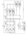
- FIG. 2 is a block diagram schematically showing the configuration of the user terminal 110 and the main server 130.
- the user terminal 110 includes a display unit 111, an imaging unit 112, a user operation unit 113, an imaging range specifying unit 114, a sensor group 115, a position detection LED 116, and communication. Part 117.
- the display unit 111 displays various images. For example, the display unit 111 displays a visualized image indicating the visualization result. In the visualized image, the effect on the space by the air conditioner 150 that affects the space included in the image captured by the imaging unit 112 is visualized. For example, the effect on the space may be indicated by at least one of a diagram, a color, and a luminance change.
- the imaging unit 112 captures an image. Specifically, the imaging unit 112 captures a target image and generates image data of the image. Here, the imaging unit 112 captures an image of a space to be visualized and generates image data of the captured image.
- the user operation unit 113 accepts an operation input from the user. For example, the user operation unit 113 accepts input of information given by the user to the captured image.
- the imaging range specifying unit 114 specifies the imaging range of an image captured based on the value obtained from the sensor group 115 and the terminal position information acquired from the position detection server 171.
- the sensor group 115 is various sensors used by the user terminal 110. For example, in the first embodiment, the sensor group 115 includes an acceleration sensor and a geomagnetic line sensor.
- the position detection LED 116 is an indicator for the indoor position detection system to detect the position of the user terminal 110.
- the communication unit 117 is an interface that performs communication via the network 190.
- FIG. 3 is a schematic diagram illustrating an example of a hardware configuration of the user terminal 110.
- the user terminal 110 includes a display 501, a camera 502, an input device 503, a communication device 504 such as a NIC (Network Interface Card), various sensors 505, and a CPU (Central Processing). Unit) or the like, a memory 507, and an LED 508.
- the display unit 111 can be realized by the processor 506 controlling the display 501.
- the imaging unit 112 can be realized by the processor 506 controlling the camera 502.
- the user operation unit 113 can be realized by the processor 506 controlling the input device 503.
- the imaging range specifying unit 114 can be realized by the processor 506 executing a program stored in the memory 507.
- the sensor group 115 can be realized by the processor 506 controlling the various sensors 505.
- the position detection LED 116 can be realized by the processor 506 controlling the LED 508.
- the communication unit 117 can be realized by the processor 506 controlling the communication device 504. Note that the display unit 111 and the user operation unit 113 may be realized by the processor 506 controlling a touch panel in which the display 501 and the input device 503 are integrated.
- the main server 130 includes an air conditioner arrangement specifying unit 131, an air conditioner influence object specifying unit 132, an air conditioner arrangement input unit 133, an air conditioner data acquisition unit 134, and an air conditioner setting.
- the acquisition unit 135, the image composition unit 136, and the communication unit 137 are provided.
- the air conditioner arrangement specifying unit 131 specifies the outlet of the air conditioner 150 in the image obtained from the imaging unit 112 of the user terminal 110.
- the air conditioner arrangement specifying unit 131 specifies the position and orientation of the air outlet of the air conditioner 150 in the image obtained from the imaging unit 112 of the user terminal 110.
- the air-conditioning influence object specifying unit 132 receives air-conditioning influence object information indicating an air-conditioning influence object such as a partition or a PC from the user operation unit 113 of the user terminal 110, and based on this, air-conditioning that affects air-conditioning by the air conditioner 150 Identify the location of the affected object.
- the air conditioner arrangement input unit 133 receives input of drawing information which is air conditioner arrangement information describing a position where the air conditioner 150 is arranged.
- drawing information is information in which a device ID for specifying the air conditioner 150 is associated with a position (for example, XY coordinates) in the room where the air conditioner 150 specified by the device ID is arranged.
- the input drawing information is stored in a storage unit (not shown).
- the air conditioner data acquisition unit 134 acquires the operation setting of the air conditioner 150 with the specified device ID via the controller 151.
- the operation setting is, for example, start / stop, wind direction, air volume, operation mode, and the like.
- the air conditioner setting acquisition unit 135 identifies one or more air conditioners 150 that affect the space included in the image captured by the imaging unit 112 from the plurality of air conditioners 150, and the one or more air conditioners.
- the operation setting of the machine 150 is acquired.
- the air conditioner setting acquisition unit 135 is based on the imaging range indicated by the imaging range information obtained from the imaging range specifying unit 114 of the user terminal 110 and the arrangement indicated by the drawing information obtained from the air conditioner arrangement input unit 133.
- the device ID of the air conditioner 150 in the image captured by the user terminal 110 is specified.
- the air conditioner setting acquisition part 135 acquires the operation setting of the air conditioner 150 corresponding to this apparatus ID by instruct
- the air conditioner 150 that affects the space included in the image captured by the image capturing unit 112 is the air conditioner 150 included in the image captured by the image capturing unit 112.
- the image composition unit 136 generates composite image data indicating a visualized image to be displayed on the display unit 111 of the user terminal 110 by combining an image indicating the airflow analysis result with an image captured by the user terminal 110.
- the influence on the space included in the image captured by the user terminal 110 is the airflow from the air conditioner 150.
- the image synthesis unit 136 synthesizes an image virtually showing the influence (airflow) of the air conditioner 150 on the space included in the image captured by the user terminal 110.
- the composite image data of the visualized image is generated.
- the communication unit 137 is an interface that performs communication via the network 190. For example, the communication unit 137 transmits the composite image data generated by the image composition unit 136 to the user terminal 110.
- FIG. 4 is a schematic diagram illustrating an example of a hardware configuration of the main server 130.
- the main server 130 includes a memory 601, a processor 602, a communication device 603, and an input interface (hereinafter referred to as input I / F) 604.
- input I / F input interface
- the processor 602 executes the program stored in the memory 601 in the air conditioner arrangement specifying unit 131, the air conditioner influence object specifying unit 132, the air conditioner data acquiring unit 134, the air conditioner setting acquiring unit 135, and the image composition unit 136. ,realizable.
- the communication unit 137 can be realized by the processor 602 controlling the communication device 603.
- the air conditioner arrangement input unit 133 can be realized by the processor 602 controlling the input I / F 604. Note that the processor 602 may realize the air conditioner arrangement input unit 133 by controlling the communication device 603 instead of the input I / F 604, and may control the air conditioner by controlling the input device such as a keyboard.
- the arrangement input unit 133 may be realized. Note that a storage unit (not shown) can be realized by the processor 602 controlling the memory 601.
- a plurality of position detection cameras 170 shown in FIG. 2 are arranged in the detection target space.
- the position detection server 171 detects the position detection LED 116 of the user terminal 110 based on the image from the position detection camera 170 by image processing. Thereby, the position detection server 171 generates position information indicating the position of the user terminal 110. For example, the position detection LED 116 emits light with a different light emission pattern for each specific terminal. Then, the position detection server 171 identifies the light emission pattern from the image obtained from the position detection camera 170, and specifies the position of the user terminal 110 based on pre-registered camera position information.
- the indoor position detection system is not limited to such an example, and is captured by the user terminal 110, which is a system in which a wireless base station is arranged to estimate the position from the radio wave intensity, the radio wave arrival time, or the number of communicable base stations
- stored previously using the acquired image may be sufficient.
- Embodiment 1 The operation of the air conditioning visualization system 100 according to Embodiment 1 will be described with reference to FIG. Note that the position detection operation of the user terminal 110 by the indoor position detection system is always performed.
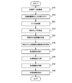
- FIG. 5 is a flowchart showing the operation of the air conditioning visualization system 100 according to the first embodiment.
- the imaging unit 112 of the user terminal 110 receives an imaging operation from the user, operates a camera module mounted on the user terminal 110, and acquires image data (S10).
- the imaging range specifying unit 114 of the user terminal 110 acquires terminal position information indicating the position of the user terminal 110 at the time when the image data is acquired from the position detection server 171 via the communication unit 117.
- the imaging range specifying unit 114 acquires the values of the acceleration sensor and the geomagnetic sensor from the sensor group 115 at the time when the image data is acquired.
- specification part 114 estimates the imaging inclination of a perpendicular direction based on the value from an acceleration sensor, and estimates the imaging direction of a horizontal direction based on the value from a geomagnetic sensor.
- specification part 114 matches these imaging directions with terminal position information, associates it with image data as imaging range information, and memorize
- the display unit 111 of the user terminal 110 displays a captured image and displays an interface for inputting a position of an air-conditioning affected object in the image such as a shielding object such as a partition or a heat source such as a PC.
- the user operation unit 113 receives the input completion operation from the user, and stores the input information in the storage unit (not shown) in association with the image data as the air-conditioning influence object information (S12).
- the user operation unit 113 analyzes the captured image, extracts heat source or shielding object candidates, and presents them to the user.
- a user selects an air-conditioning influence object from the extracted candidate, and designates the classification (for example, heat source or shielding object) of an air-conditioning influence object.
- the user operation unit 113 can also specify the position in the depth direction of the selected air-conditioning affected object by pattern matching with an image of an object likely to be in the office. And the user operation part 113 produces
- the communication unit 117 of the user terminal 110 transmits the image data of the captured image, the imaging range information, and the air-conditioning influence object information to the main server 130 (S13).
- the air conditioning influence object specifying unit 132 of the main server 130 stores the received air conditioning influence object information as it is in a storage unit (not shown).
- the air-conditioning influence object information is input from the user terminal 110 and used as it is.
- the air-conditioning influence object specifying unit 132 automatically specifies the pattern data based on the image data. May be.
- the air conditioner arrangement specifying unit 131 of the main server 130 specifies the position and orientation of the outlet in the image based on the acquired image data (S14). Specifically, the air conditioner arrangement specifying unit 131 specifies the position and inclination of the air outlet by pattern matching with the appearance image of the air conditioner 150.
- the air conditioner setting acquisition unit 135 of the main server 130 specifies the device ID of the air conditioner 150 in the image indicated by the image data based on the imaging range information and the drawing information acquired from the air conditioner arrangement input unit 133 ( S15).
- the air conditioner setting acquisition unit 135 is included in the image indicated by the image data from the user terminal 110 based on the position of the user terminal 110 indicated by the imaging range information and the shooting direction in the vertical direction and the horizontal direction.
- the device ID of the air conditioner 150 is identified.
- the angle of view of the image indicated by the image data can be estimated by using the precondition that the surface on which the air conditioner 150 (square) is a flat surface.
- the angle of view may be included as metadata of the image data.
- the air conditioner setting acquisition unit 135 of the main server 130 acquires the operation settings (start / stop, wind direction, air volume, operation mode, etc.) of the air conditioner 150 corresponding to the specified device ID via the air conditioner data acquisition unit 134. (S16).
- the image compositing unit 136 of the main server 130 determines the position and direction of the specified outlet, the obtained air direction and air volume of the air conditioner 150, and the position of the air-conditioning influence object transmitted and stored from the user terminal 110.
- An airflow analysis is performed in consideration of the interference between the blown-out winds and the bending due to the shield (S17).
- the image composition unit 136 specifies the arrangement of the air conditioner 150 and the air-conditioning influence object in the room based on the drawing information and the air-conditioning influence object information, and sets the operation setting of the air conditioner 150 and the outlet.
- the airflow from the outlet of the air conditioner 150 is specified by performing a known simulation from the position and orientation of the air conditioner.
- the image composition unit 136 of the main server 130 generates composite image data (visualized image data) of a composite image (visualized image) in which the result of the airflow analysis is superimposed on the image indicated by the image data (S18). For example, the image composition unit 136 estimates the simulation result (three-dimensional) from the position and orientation of the user terminal 110 specified by the imaging range information and the image indicated by the image data from the user terminal 110. A two-dimensional image corresponding to the angle of view is generated. Then, the image composition unit 136 generates composite image data by superimposing the virtual image generated in this way on the image indicated by the image data from the user terminal 110. In the first embodiment, the result of the airflow analysis is superimposed on the image data. However, the image composition unit 136 generates an image that simulates the position of the air conditioner 150, the position of the air outlet, the air-conditioning influence object, and the like. The operation of superimposing the results of the airflow analysis may be used.
- the communication unit 137 of the main server 130 transmits the generated composite image data to the user terminal 110 (S19).
- the communication unit 117 receives the composite image data, and the composite image is displayed on the display unit 111 based on the composite image data (S20).
- FIG. 6 is a schematic diagram illustrating an example of a composite image displayed on the user terminal 110.
- the composite image IM includes an air conditioner 150 and a cabinet CA as an air-conditioning influence object, and the flow of airflow from the air conditioner 150 is indicated by an arrow. Yes.
- the airflow from the air conditioner 150 collides with the airflow from the opposing air conditioner 150 and flows downward, and further changes its direction by hitting the cabinet CA.
- a user who is dissatisfied with the air-conditioning environment (especially wind perception) has an image of the space in the imaging unit 112 provided in the user terminal 110.
- the flow of wind can be confirmed simply by imaging.
- a user can change into a desired air-conditioning environment by changing a setting with the controller 151.
- the air conditioning visualization system 100 performs visualization in consideration of airflow interference from a plurality of outlets and turbulence of airflow due to shielding. That is, airflows from a plurality of outlets are synthesized. For this reason, the user can confirm the flow of the wind which cannot be inferred only by the direction of the visually observable outlet. Furthermore, the user can perform visualization that reflects in detail the operation settings of the air conditioner 150 in the automatically imaged range without inputting the operation status of the air conditioner 150.
- the air conditioner arrangement specifying unit 131 specifies the outlet from the image indicated by the image data, but the processing of the air conditioner arrangement specifying unit 131 is not limited to such an example.
- the air conditioner arrangement specifying unit 131 may estimate the position of the outlet based on the imaging range information and the drawing information acquired from the air conditioner arrangement input unit 133. By doing so, even when the air conditioner 150 is not present in the image, the airflow by the surrounding air conditioners 150 can be visualized.
- the direction of the air outlet may be a predetermined direction or may be estimated based on the operation setting acquired by the air conditioner setting acquisition unit 135.
- the air conditioner arrangement specifying unit 131 specifies the air outlet from the pattern matching between the air conditioner appearance image held in advance and the image indicated by the image data.
- the processing in is not limited to such an example.
- the air conditioner arrangement specifying unit 131 uses the device ID specified by the air conditioner setting acquisition unit 135 to change the wind direction setting of the air conditioner 150 corresponding to this device ID, and the image data acquired at that time A location where the image shown in FIG. By doing so, the accuracy of pattern matching can be improved.
- a plurality of LEDs may be arranged in the air conditioner 150, and the air conditioner arrangement specifying unit 131 may specify the outlet from the LED arrangement on the image.
- the accuracy of pattern matching can be improved.
- the air conditioner 150 is an indoor unit having a four-way outlet, the outlet can be accurately specified by arranging the LEDs diagonally.
- the air conditioner appearance image for performing pattern matching may be changed according to the model information acquired based on the device ID specified by the air conditioner setting acquisition unit 135. By doing so, the accuracy of pattern matching can be improved.
- the image composition unit 136 is configured to perform the airflow analysis.
- the temperature distribution around the air conditioner based on the suction temperature or the set temperature information. And may be visualized by coloring the composite image. By doing so, temperature irregularities in the target space can be visualized.
- the analysis result is combined with the captured image and displayed, but the operation setting may be changed by an operation on the user terminal 110.
- the user operation unit 113 performs such an operation by moving the airflow of the displayed composite image on the touch panel. Generate a corresponding instruction command.
- the user operation unit 113 transmits the generated instruction command to the controller 151 via the communication unit 117 or transmits the instruction command to the controller 151 via the main server 130 to directly operate the airflow. You can easily change the settings.
- analysis and image synthesis are performed on the entire captured image.
- the user designates an important analysis point by an operation on the user terminal 110, and only the air flow related to the designated point is analyzed. Then, the analysis result may be displayed with emphasis. By doing so, the information required by the user can be visualized with a small amount of calculation.
- the controller 151 causes the combination of operation settings of the air conditioner 150 in the image. Therefore, a setting that satisfies the request may be automatically searched and executed. By doing so, the air-conditioning setting according to a user request can be implemented easily.
- FIG. 7 is a block diagram schematically showing the configuration of the air conditioning visualization system 200 according to the second embodiment.
- the air conditioning visualization system 200 includes a user terminal 210 and a main server 230.
- the air conditioning system to be visualized includes an air conditioner 250 and a controller 151. They are connected by a network.
- the user terminal 210, the main server 230, and the controller 151 are connected via a network 190.
- the indoor position detection system is not provided.
- FIG. 8 is a block diagram schematically showing the configuration of the user terminal 210 and the main server 230.
- the user terminal 210 includes a display unit 111, an imaging unit 112, a user operation unit 113, and a communication unit 117.
- the user terminal 210 in the second embodiment does not include the imaging range specifying unit 114, the sensor group 115, and the position detection LED 116.
- the air conditioner 250 has a device identification LED 250a as an indicator that operates with a different light emission pattern for each device ID. Yes.
- the main server 230 includes an air conditioner arrangement specifying unit 131, an air-conditioning influence object specifying unit 132, an air conditioner data acquisition unit 134, an air conditioner setting acquisition unit 235, and an image composition unit. 136 and a communication unit 137.
- the main server 230 in the second embodiment is the same as the main server 130 in the first embodiment except that the main server 230 does not include the air conditioner arrangement input unit 133 and the processing in the air conditioner setting acquisition unit 235. It is configured.
- the air conditioner setting acquisition unit 235 identifies the light emission pattern of the device identification LED 250a from the image indicated by the image data transmitted from the user terminal 210, and identifies the device ID. And the air conditioner setting acquisition part 235 acquires the operation setting of the air conditioner 250 corresponding to specified apparatus ID.
- FIG. 9 is a flowchart showing the operation of the air conditioning visualization system 200 according to the second embodiment.
- the same reference numerals as those in FIG. 5 are given to the steps performing the same processing as the steps shown in FIG. 5, and the detailed description thereof will be omitted.
- step S10 shown in FIG. 9 is the same as the process in step S10 shown in FIG. However, after step S10 shown in FIG. 9, the process proceeds to step S12.
- step S12 shown in FIG. 9 is the same as the process in step S12 shown in FIG. However, after step S12 shown in FIG. 9, the process proceeds to step S23.
- step S ⁇ b> 23 the communication unit 117 of the user terminal 210 transmits image data of the captured image and air-conditioning influence object information to the main server 230. Then, the process proceeds to step S14.
- the process in step S14 shown in FIG. 9 is the same as the process in step S14 shown in FIG. However, after step S14 shown in FIG. 9, the process proceeds to step S25.
- step S25 the air conditioner setting acquisition unit 235 identifies the light emission pattern of the device identification LED 250a from the image indicated by the image data transmitted from the user terminal 210, and identifies the device ID. Then, the process proceeds to step S16.
- the processing in steps S16 to S20 in FIG. 9 is the same as the processing in steps S16 to S20 in FIG.
- visualization of the air conditioning system can be realized without assuming an indoor position detection system and without performing initial setting for each property such as drawing information. .
- the air conditioning visualization system 300 includes a user terminal 210 and a main server 330.
- the air conditioning system to be visualized includes an air conditioner 150 and a controller 351. They are connected by a network.
- Air conditioner 150 in the third embodiment is the same as that in the first embodiment.
- the controller 351 controls the air conditioner 150 in accordance with an instruction from the main server 330.
- the user terminal 210, the main server 330, and the controller 351 are connected via a network 190.
- the indoor position detection system is not provided as in the second embodiment.
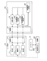
- FIG. 10 is a block diagram schematically showing the configuration of the user terminal 210 and the main server 330. As shown in FIG. 10, the user terminal 210 is configured in the same manner as in the second embodiment.
- the main server 330 includes an air conditioner arrangement specifying unit 131, an air conditioner influence object specifying unit 132, an air conditioner arrangement input unit 133, an air conditioner data acquisition unit 134, and an air conditioner setting.
- An acquisition unit 335, an image composition unit 136, a communication unit 137, and an air conditioner operation control unit 338 are provided.
- the main server 330 in the third embodiment is the same as the main server 230 in the second embodiment except that the air conditioner operation control unit 338 is further provided and the processing in the air conditioner setting acquisition unit 335 is performed. It is constituted similarly.
- the air conditioner operation control unit 338 controls the air conditioner 150 in accordance with an instruction from the air conditioner setting acquisition unit 335. For example, the air conditioner operation control unit 338 controls the air conditioner 150 by transmitting an instruction command to the controller 351 via the communication unit 137.
- the air conditioner operation control unit 338 sequentially changes the operation settings of the plurality of air conditioners 150 so that the appearance of the air conditioner 150 changes based on the operation settings acquired by the air conditioner data acquisition unit 134.
- the air conditioner setting acquisition unit 335 sequentially controls the air conditioners 150 via the air conditioner operation control unit 338, and the image indicated by the image data sent from the user terminal 210 becomes the content after control.
- the device ID is specified by checking whether or not there is.
- the air conditioner setting acquisition unit 335 includes the air conditioner 150 included in the image depending on whether or not a change in the operation setting instructed by the air conditioner operation control unit 338 appears in the image captured by the imaging unit 112. Is identified.
- the air conditioner setting acquisition part 335 acquires the operation setting of the air conditioner 150 corresponding to specified apparatus ID.
- FIG. 11 is a flowchart showing the operation of the air conditioning visualization system 300 according to the third embodiment.
- the same reference numerals as those in FIG. 9 are given to steps performing the same processing as the steps shown in FIG. 9, and detailed description thereof will be omitted.
- steps S10 to S14 shown in FIG. 11 is the same as the processing in steps S10 to S14 shown in FIG. However, after step S14 shown in FIG. 11, the process proceeds to step S35.
- step S ⁇ b> 35 the air conditioner setting acquisition unit 335 specifies the device ID based on the image data transmitted from the user terminal 210. Details of the processing in step S35 will be described with reference to FIG. And after the process of step S35, a process progresses to step S16.
- the processing in steps S16 to S20 in FIG. 11 is the same as the processing in steps S16 to S20 in FIG.
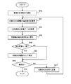
- FIG. 12 is a flowchart showing the identification process of the air conditioner 150 in step S35 of FIG. Here, it is assumed that the device IDs are assigned to the plurality of air conditioners 150 in order.
- the air conditioner setting acquisition unit 335 sets the first device ID of the air conditioner 150 as a target ID (S40).
- the air conditioner setting acquisition unit 335 acquires the air direction setting of the air conditioner 150 via the air conditioner data acquisition unit 134 and stores it in a storage unit (not shown), and then the air conditioner operation control unit 338. Then, the air direction setting of the air conditioner 150 corresponding to the target ID is instructed to be different from the current setting (S41).
- the air conditioner setting acquisition unit 335 monitors the image data acquired from the imaging unit 112 for a predetermined time (for example, 1 minute) necessary for changing the air direction of the air conditioning system (S42).
- the air conditioner setting acquisition unit 335 returns the wind direction setting of the air conditioner 150 corresponding to the target ID to the pre-change wind direction setting stored in step S41 via the air conditioner operation control unit 338 (S43).
- step S44 judges whether the change of the image shown by image data corresponds with the change of a wind direction setting based on the monitoring result in step S42 (S44). If they match (YES in S44), the process proceeds to step S45. If they do not match (NO in S44), the process proceeds to step S46.
- step S45 the air conditioner setting acquisition unit 335 identifies the target ID as the device ID of the air conditioner 150 in the image. Then, the process proceeds to step S46.
- step S46 the air conditioner setting acquisition unit 335 determines whether the target ID has reached the final value of the device ID. If the final value has been reached (YES in S46), the process ends. If the final value has not been reached (NO in S46), the process proceeds to step S47.
- step S47 the air conditioner setting acquisition unit 335 changes the target ID to the next device ID. Then, the process returns to step S41.
- a device is added to the air conditioner 150 without assuming an indoor position detection system and without initial setting for each property such as drawing information. Visualization of the air conditioning system can be realized.
- the air conditioner setting acquisition units 135 to 335 specify the device ID of the air conditioner in the image using an indoor position detection system or the like, and acquire the operation setting from the air conditioning system.
- the processing in the air conditioner setting acquisition units 135 to 335 is not limited to such an example.
- the air conditioner 450 includes an operation setting LED 450 a that is an indicator that emits light with a different light emission pattern according to the operation setting
- the air conditioner setting acquisition unit 435 emits the light.
- the driving setting can be acquired from the pattern.
- FIG. 13 shows the user terminal 210 and the main server 430 based on the second or third embodiment, such a modification can be applied to the first embodiment.
- the air conditioner outlet that affects the space included in the image captured by the imaging unit can be identified from the image captured by the imaging unit. Can be easily analyzed. Moreover, since the influence of the airflow from a plurality of outlets can be analyzed, the influence of the air conditioner on the space in the image can be confirmed more accurately.
- the airflow affected by the air-conditioning influence object can be confirmed.
- the air conditioner in the image can be specified more accurately and easily. Furthermore, if the operation setting can be identified by the indicator, the operation setting of the target air conditioner can be acquired without performing communication with the air conditioning system.
- the air conditioner in the image can be easily obtained by the imaging range of the image captured by the imaging unit and the air conditioner arrangement information indicating the position where each of the plurality of air conditioners is installed. Can be specified.
- the user's sensible temperature can be easily confirmed.
- the user can easily confirm the influence of the air conditioner by synthesizing an image that virtually represents the influence of the air conditioner on the image picked up by the image pickup unit.
- Air conditioning visualization system 110, 210 User terminal, 111 Display unit, 112 Imaging unit, 113 User operation unit, 114 Imaging range specifying unit, 115 Sensor group, 116 Position detection LED, 117 Communication unit, 130, 230, 330, 430 main server, 131 air conditioner arrangement specifying unit, 132 air conditioner affected object specifying unit, 133 air conditioner arrangement input unit, 134 air conditioner data acquisition unit, 135, 235, 335, 435 air conditioner setting acquisition unit, 136 Image composition unit, 137 communication unit, 338 air conditioner operation control unit, 150, 250, 450 air conditioner, 250a device identification LED, 450a operation setting LED, 151,351 controller, 170 position detection camera, 17 Position detection server, 190 network.
Landscapes
- Engineering & Computer Science (AREA)
- General Engineering & Computer Science (AREA)
- Mechanical Engineering (AREA)
- Chemical & Material Sciences (AREA)
- Combustion & Propulsion (AREA)
- Human Computer Interaction (AREA)
- Physics & Mathematics (AREA)
- Signal Processing (AREA)
- Automation & Control Theory (AREA)
- General Physics & Mathematics (AREA)
- Fuzzy Systems (AREA)
- Mathematical Physics (AREA)
- Air Conditioning Control Device (AREA)
Abstract
Description
これに対し、特許文献1に記載された空調ユニットでは、カメラで空調機を撮像し、空調機に設定されている風向、風速又は運転モード等の運転設定を、撮像画像に合成して表示部で表示している。これにより、表示部に表示された画面上で、運転設定を可視化することができる。
複数の空調機が配置されるオフィスビル向けの空調システムでは、どの空調機が撮像画像内に存在するのかを識別しなければならない。
また、複数の空調機が配置されるオフィスビル向けの空調システムでは、隣接する空調機の吹き出し風により気流が複雑化する。こうした気流を可視化するには、複数の室内機が含まれた画像を用いることが有効であるが、特許文献1に記載された技術では、各空調機の運転設定を反映することが困難であった。
図1は、実施の形態1に係る空調可視化システム100の構成を概略的に示すブロック図である。
図1に示されているように、空調可視化システム100は、ユーザ端末110と、メインサーバ130とを備える。
可視化対象となる空調システムは、複数の空調機150と、コントローラ151とを備える。それらは、ネットワークで接続されている。
ユーザ端末110の位置を検出する屋内位置検出システムは、位置検出用カメラ170と、位置検出用サーバ171とを備える。それらは、ネットワークで接続されている。
ユーザ端末110、メインサーバ130、コントローラ151、位置検出用サーバ171は、ネットワーク190で接続されている。
図2に示されているように、ユーザ端末110は、表示部111と、撮像部112と、ユーザ操作部113と、撮像範囲特定部114と、センサ群115と、位置検出用LED116と、通信部117とを備える。
撮像部112は、画像を撮像する。具体的には、撮像部112は、対象の画像を撮影し、その画像の画像データを生成する。ここでは、撮像部112は、可視化対象の空間の画像を撮像し、撮像された画像の画像データを生成する。
撮像範囲特定部114は、センサ群115から得られる値と、位置検出用サーバ171から取得した端末位置情報とにより撮像された画像の撮像範囲を特定する。
センサ群115は、ユーザ端末110で利用する各種センサである。例えば、実施の形態1では、センサ群115は、加速度センサ及び地磁気線センサを含む。
通信部117は、ネットワーク190を介して通信を行うインタフェースである。
図3に示されているように、ユーザ端末110は、ディスプレイ501と、カメラ502と、入力装置503と、NIC(Network Interface Card)等の通信装置504と、各種センサ505と、CPU(Central Processing Unit)等のプロセッサ506と、メモリ507と、LED508とを備える。
なお、表示部111及びユーザ操作部113は、ディスプレイ501と入力装置503とが一体化されたタッチパネルをプロセッサ506が制御することで、実現されてもよい。
空調影響物特定部132は、ユーザ端末110のユーザ操作部113から、パーティション又はPC等の空調影響物を示す空調影響物情報を受け取り、これに基づいて、空調機150による空調に影響を与える空調影響物の位置を特定する。
空調機データ取得部134は、コントローラ151を介して、指定された機器IDの空調機150の運転設定を取得する。ここで、運転設定は、例えば、発停、風向、風量及び運転モード等である。
通信部137は、ネットワーク190を介して通信を行うインタフェースである。例えば、通信部137は、画像合成部136で生成された合成画像データをユーザ端末110に送信する。
図4に示されているように、メインサーバ130は、メモリ601と、プロセッサ602と、通信装置603と、入力インタフェース(以下、入力I/Fという)604とを備える。
位置検出用サーバ171は、位置検出用カメラ170からの画像を元に、ユーザ端末110の位置検出用LED116を画像処理により検出する。これにより、位置検出用サーバ171は、ユーザ端末110の位置を示す位置情報を生成する。
例えば、位置検出用LED116は、特定の端末毎に異なる発光パターンで発光している。そして、位置検出用サーバ171は、位置検出用カメラ170から得られる画像から、その発光パターンを識別し、予め登録されているカメラ位置情報に基づいて、ユーザ端末110の位置を特定する。
なお、屋内位置検出システムによるユーザ端末110の位置検出動作は、常時実行されている。
まず、ユーザ端末110の撮像部112は、ユーザからの撮像操作を受けて、ユーザ端末110に搭載されているカメラモジュールを動作させて画像データを取得する(S10)。
メインサーバ130の空調影響物特定部132は、受信した空調影響物情報をそのまま図示しない記憶部に記憶する。なお、実施の形態1では、空調影響物情報をユーザ端末110から入力して、そのまま用いる動作としたが、空調影響物特定部132が画像データに基づいて、パターンマッチング等により、自動で特定してもよい。
ここでは、画像合成部136は、例えば、図面情報及び空調影響物情報に基づいて、部屋における、空調機150及び空調影響物の配置を特定して、空調機150の運転設定、並びに、吹き出し口の位置及び向きから、公知のシミュレーションを行うことで、空調機150の吹き出し口からの気流を特定している。
例えば、画像合成部136は、上述のシミュレーションの結果(3次元)を、撮像範囲情報で特定されるユーザ端末110の位置及び向き、並びに、ユーザ端末110からの画像データで示される画像から推定される画角に対応した2次元の画像を生成する。そして、画像合成部136は、このようにして生成した仮想的な画像を、ユーザ端末110からの画像データで示される画像に重畳することで、合成画像データを生成する。
なお、実施の形態1では、気流解析の結果を画像データに重畳する動作としたが、画像合成部136は、空調機150の位置、吹き出し口の位置及び空調影響物等を模擬表現した画像に、気流解析の結果を重畳する動作としてもよい。
ユーザ端末110では、通信部117で合成画像データを受信して、その合成画像データに基づいて、合成画像が表示部111に表示される(S20)。
図6に示されているように、合成画像IMには、空調機150と、空調影響物としてのキャビネットCAとが含まれており、空調機150からの気流の流れが、矢印で示されている。図5に示されているように、空調機150からの気流は、対向する空調機150からの気流とぶつかり下方に流れ、さらに、キャビネットCAにぶつかることで、方向が変わっている。
図7は、実施の形態2に係る空調可視化システム200の構成を概略的に示すブロック図である。
図7に示されているように、空調可視化システム200は、ユーザ端末210と、メインサーバ230とを備える。
可視化対象となる空調システムは、空調機250と、コントローラ151とを備える。それらは、ネットワークで接続されている。
ユーザ端末210、メインサーバ230及びコントローラ151は、ネットワーク190で接続されている。
ここで、実施の形態2では、実施の形態1とは異なり、屋内位置検出システムが設けられていない。
図8に示されているように、ユーザ端末210は、表示部111と、撮像部112と、ユーザ操作部113と、通信部117とを備える。実施の形態2におけるユーザ端末210は、実施の形態1におけるユーザ端末110とは異なり、撮像範囲特定部114、センサ群115及び位置検出用LED116を備えていない。
実施の形態2におけるメインサーバ230は、空調機配置入力部133を備えていない点、及び、空調機設定取得部235での処理の点を除いて、実施の形態1におけるメインサーバ130と同様に構成されている。
図9に示されているステップにおいて、図5に示されているステップと同様の処理を行っているステップには、図5と同様の符号を付し、その詳細な説明を省略する。
図9に示されているステップS12での処理は、図5に示されているステップS12での処理と同様である。但し、図9に示されているステップS12の後には、処理はステップS23に進む。
図9に示されているステップS14での処理は、図5に示されているステップS14での処理と同様である。但し、図9に示されているステップS14の後には、処理はステップS25に進む。
図9のステップS16~S20での処理は、図5のステップS16~S20での処理と同様である。
図7に示されているように、実施の形態3に係る空調可視化システム300は、ユーザ端末210と、メインサーバ330とを備える。
可視化対象となる空調システムは、空調機150と、コントローラ351とを備える。それらは、ネットワークで接続されている。実施の形態3における空調機150は、実施の形態1と同様である。一方、コントローラ351は、メインサーバ330からの指示に応じて、空調機150を制御する。
ユーザ端末210、メインサーバ330及びコントローラ351は、ネットワーク190で接続されている。
ここで、実施の形態3でも、実施の形態2と同様に、屋内位置検出システムが設けられていない。
図10に示されているように、ユーザ端末210は、実施の形態2と同様に構成されている。
実施の形態3におけるメインサーバ330は、空調機運転制御部338がさらに設けられている点、及び、空調機設定取得部335での処理の点を除いて、実施の形態2におけるメインサーバ230と同様に構成されている。
図11に示されているステップにおいて、図9に示されているステップと同様の処理を行っているステップには、図9と同様の符号を付し、その詳細な説明を省略する。
図11のステップS16~S20での処理は、図9のステップS16~S20での処理と同様である。
ここでは、機器IDが、複数の空調機150に順番に割り振られているものとする。
次に、空調機設定取得部335は、空調機データ取得部134を介して、空調機150の風向設定を取得して、図示しない記憶部に記憶させた上で、空調機運転制御部338を介して、対象IDに対応する空調機150の風向設定を現設定とは異なる設定を指示する(S41)。
例えば、図13に示されているように、空調機450が、運転設定に応じて異なる発光パターンで発光するインジケータである運転設定LED450aを備える場合には、空調機設定取得部435は、その発光パターンから運転設定を取得することができる。そうすることで、屋内位置検出システムを使わずに、また、空調システムとの通信手段を用意することなく、空調システムを可視化することができる。なお、図13では、実施の形態2又は3に基づいて、ユーザ端末210及びメインサーバ430を示しているが、実施の形態1に対しても、このような変形例を適用することができる。
以上に記載された実施の形態では、撮像部で撮像された画像から、撮像部で撮像された映像に含まれている空間に影響を与える空調機の吹き出し口を特定することができるため、気流の解析を容易に行うことができる。
また、複数の吹き出し口からの気流の影響を解析することができるため、より正確に画像内の空間への空調機の影響を確認することができる。
さらに、インジケータにより、運転設定を識別することができれば、空調システムとの通信を行うことなく、対象となる空調機の運転設定を取得することができる。
Claims (12)
- 画像を撮像する撮像部と、
前記画像に含まれている空間に影響を与える少なくとも1つの空調機を複数の空調機から特定し、当該少なくとも1つの空調機の運転設定を取得する空調機設定取得部と、
前記少なくとも1つの空調機による前記空間への影響を可視化した可視化画像を表示する表示部と、を有すること
を特徴とする空調可視化システム。 - 前記空調機設定取得部は、前記撮像部で撮像された画像に含まれている空調機を、前記空間に影響を与える空調機として特定すること
を特徴とする請求項1に記載の空調可視化システム。 - 前記撮像部で撮像された画像に含まれている空調機の吹き出し口を特定する空調機配置特定部をさらに備え、
前記空間への影響は、前記特定された吹き出し口からの気流であること
を特徴とする請求項2に記載の空調可視化システム。 - 前記撮像部で撮像された画像に複数の吹き出し口が含まれている場合には、
前記空間への影響は、前記複数の吹き出し口からの気流が合成されていること
を特徴とする請求項3に記載の空調可視化システム。 - 前記撮像部で撮像された画像に含まれている空調機の吹き出し口を特定する空調機配置特定部と、
前記撮像部で撮像された画像に含まれている空調機による空調に影響を与える空調影響物の位置を特定する空調影響物特定部と、をさらに備え、
前記空間への影響は、前記空調影響物により影響された、前記特定された吹き出し口からの気流であること
を特徴とする請求項2に記載の空調可視化システム。 - 前記複数の空調機は、それぞれを識別するための第1のインジケータを有しており、
前記空調機設定取得部は、前記撮像部で撮像された画像に含まれている第1のインジケータにより、前記撮像部で撮像された画像に含まれている空調機を特定すること
を特徴とする請求項2から5の何れか一項に記載の空調可視化システム。 - 前記複数の空調機は、運転設定を識別するための第2のインジケータを有しており、
前記空調機設定取得部は、前記撮像部で撮像された画像に含まれている第2のインジケータにより、前記撮像部で撮像された画像に含まれている空調機の運転設定を取得すること
を特徴とする請求項2から6の何れか一項に記載の空調可視化システム。 - 前記撮像部により撮像された画像の撮像範囲を特定する撮像範囲特定部と、
前記複数の空調機の各々が設置されている位置を示す空調機配置情報を記憶する記憶部と、をさらに備え、
前記空調機設定取得部は、前記空調機配置情報に基づいて、前記撮像範囲特定部で特定された撮像範囲に含まれている空調機を、前記空間に影響を与える空調機として特定すること
を特徴とする請求項1から5の何れか一項に記載の空調可視化システム。 - 前記複数の空調機のコントローラを介して、前記複数の空調機の各々の運転設定を取得する空調機データ取得部をさらに備え、
前記空調機設定取得部は、前記空調機データ取得部に指示することで、前記空間に影響を与える空調機の運転設定を取得すること
を特徴とする請求項1から7の何れか一項に記載の空調可視化システム。 - 前記複数の空調機のコントローラを介して、前記複数の空調機の各々の運転設定を取得する空調機データ取得部と、
前記コントローラに指示することで、前記複数の空調機の各々の運転設定を制御する空調機運転制御部と、をさらに備え、
前記空調機運転制御部は、前記空調機データ取得部で取得された運転設定に基づいて、前記複数の空調機の外観が変化するように、前記複数の空調機の運転設定を順番に変化させ、前記空調機設定取得部は、前記撮像部で撮像された画像に当該変化が表れるか否かにより、前記画像に含まれている空間に影響を与える空調機を特定すること
を特徴とする請求項2から5の何れか一項に記載の空調可視化システム。 - 前記空間への影響は、前記少なくとも1つの空調機による前記空間の温度分布であること
を特徴とする請求項1に記載の空調可視化システム。 - 前記少なくとも1つの空調機による前記空間への影響を仮想的に表す画像を、前記撮像部で撮像された画像に合成することで、前記可視化画像を生成する合成部をさらに備えること
を特徴とする請求項1から11の何れか一項に記載の空調可視化システム。
Priority Applications (5)
| Application Number | Priority Date | Filing Date | Title |
|---|---|---|---|
| US16/081,625 US10928085B2 (en) | 2016-05-11 | 2016-05-11 | Air conditioning visualization system |
| PCT/JP2016/063965 WO2017195286A1 (ja) | 2016-05-11 | 2016-05-11 | 空調可視化システム |
| CN201680085416.5A CN109073252B (zh) | 2016-05-11 | 2016-05-11 | 空调可视化系统 |
| EP16901634.2A EP3457042A4 (en) | 2016-05-11 | 2016-05-11 | VISUALIZATION SYSTEM FOR AIR CONDITIONING |
| JP2018516257A JP6522237B2 (ja) | 2016-05-11 | 2016-05-11 | 空調可視化システム |
Applications Claiming Priority (1)
| Application Number | Priority Date | Filing Date | Title |
|---|---|---|---|
| PCT/JP2016/063965 WO2017195286A1 (ja) | 2016-05-11 | 2016-05-11 | 空調可視化システム |
Publications (1)
| Publication Number | Publication Date |
|---|---|
| WO2017195286A1 true WO2017195286A1 (ja) | 2017-11-16 |
Family
ID=60266412
Family Applications (1)
| Application Number | Title | Priority Date | Filing Date |
|---|---|---|---|
| PCT/JP2016/063965 Ceased WO2017195286A1 (ja) | 2016-05-11 | 2016-05-11 | 空調可視化システム |
Country Status (5)
| Country | Link |
|---|---|
| US (1) | US10928085B2 (ja) |
| EP (1) | EP3457042A4 (ja) |
| JP (1) | JP6522237B2 (ja) |
| CN (1) | CN109073252B (ja) |
| WO (1) | WO2017195286A1 (ja) |
Cited By (6)
| Publication number | Priority date | Publication date | Assignee | Title |
|---|---|---|---|---|
| JP2019139491A (ja) * | 2018-02-09 | 2019-08-22 | Necソリューションイノベータ株式会社 | 位置情報管理装置、位置情報管理システム、位置情報管理方法、およびプログラム |
| JP2020012568A (ja) * | 2018-07-13 | 2020-01-23 | 三菱重工サーマルシステムズ株式会社 | 制御装置、制御システム、制御方法及びプログラム |
| US11525591B2 (en) | 2019-03-19 | 2022-12-13 | Ebm-Papst Mulfingen Gmbh & Co. Kg | Positioning system and method for determining the position of fans |
| JPWO2024052949A1 (ja) * | 2022-09-05 | 2024-03-14 | ||
| US12345430B2 (en) | 2020-05-26 | 2025-07-01 | Mitsubishi Electric Corporation | Air-conditioning operation terminal, computer-readable medium and air-conditioning system |
| US12548104B2 (en) | 2021-12-17 | 2026-02-10 | Mitsubishi Electric Corporation | Presentation information generation device and presentation information generation method |
Families Citing this family (5)
| Publication number | Priority date | Publication date | Assignee | Title |
|---|---|---|---|---|
| GB2582796B (en) * | 2019-04-03 | 2021-11-03 | Dyson Technology Ltd | Control of a fan assembly |
| US11655995B2 (en) * | 2019-05-02 | 2023-05-23 | Lg Electronics Inc. | Method of controlling operation of air conditioner by analyzing user's behavior pattern and air conditioner |
| KR102661642B1 (ko) * | 2019-08-14 | 2024-04-29 | 삼성전자주식회사 | 전자 장치 및 전자 장치의 제어 방법 |
| CA3153263A1 (en) | 2019-09-05 | 2021-03-11 | Barksdale, Inc. | Adaptive control of electricity consumption |
| WO2021046219A1 (en) * | 2019-09-05 | 2021-03-11 | Barksdale, Inc. | Subsidiary interaction of controllers |
Citations (3)
| Publication number | Priority date | Publication date | Assignee | Title |
|---|---|---|---|---|
| JP2014202366A (ja) * | 2013-04-01 | 2014-10-27 | ダイキン工業株式会社 | 空気調和装置の操作システム及び操作方法 |
| JP2015048956A (ja) * | 2013-08-30 | 2015-03-16 | 日立アプライアンス株式会社 | 空気調和機 |
| JP2015148410A (ja) * | 2014-02-07 | 2015-08-20 | 株式会社東芝 | 空調制御装置、空調制御システム、空調制御方法及びプログラム |
Family Cites Families (12)
| Publication number | Priority date | Publication date | Assignee | Title |
|---|---|---|---|---|
| US7126558B1 (en) * | 2001-10-19 | 2006-10-24 | Accenture Global Services Gmbh | Industrial augmented reality |
| DE60213746T2 (de) * | 2001-11-28 | 2007-08-16 | Matsushita Electric Industrial Co., Ltd., Kadoma | Sicherheitssystem für ein Haus |
| US7248942B2 (en) * | 2004-02-19 | 2007-07-24 | Hewlett-Packard Development Company, L.P. | Airflow detection system having an airflow indicating device |
| JP5484205B2 (ja) * | 2010-06-09 | 2014-05-07 | 三菱電機株式会社 | 空気調和機 |
| JP2012172910A (ja) * | 2011-02-22 | 2012-09-10 | Panasonic Corp | 室内環境調整用機器の操作システム |
| US8761811B2 (en) * | 2012-04-27 | 2014-06-24 | Oracle International Corporation | Augmented reality for maintenance management, asset management, or real estate management |
| US9020278B2 (en) * | 2012-06-08 | 2015-04-28 | Samsung Electronics Co., Ltd. | Conversion of camera settings to reference picture |
| CN104321592B (zh) * | 2013-02-20 | 2017-10-20 | 松下电器(美国)知识产权公司 | 便携信息终端及其控制方法、以及记录介质 |
| JP2014190686A (ja) | 2013-03-28 | 2014-10-06 | Daikin Ind Ltd | 端末装置及びそれを備えた空調ユニット |
| KR102105463B1 (ko) * | 2013-09-02 | 2020-04-28 | 엘지전자 주식회사 | 이동 단말기 및 그것의 제어 방법 |
| CN104896685B (zh) * | 2014-03-03 | 2019-06-28 | 松下电器(美国)知识产权公司 | 传感方法、传感系统及包含它们的空调设备 |
| JP6271083B2 (ja) * | 2015-04-07 | 2018-01-31 | 三菱電機株式会社 | 空気調和機のメンテナンスサポートシステム |
-
2016
- 2016-05-11 EP EP16901634.2A patent/EP3457042A4/en not_active Withdrawn
- 2016-05-11 WO PCT/JP2016/063965 patent/WO2017195286A1/ja not_active Ceased
- 2016-05-11 US US16/081,625 patent/US10928085B2/en not_active Expired - Fee Related
- 2016-05-11 CN CN201680085416.5A patent/CN109073252B/zh active Active
- 2016-05-11 JP JP2018516257A patent/JP6522237B2/ja not_active Expired - Fee Related
Patent Citations (3)
| Publication number | Priority date | Publication date | Assignee | Title |
|---|---|---|---|---|
| JP2014202366A (ja) * | 2013-04-01 | 2014-10-27 | ダイキン工業株式会社 | 空気調和装置の操作システム及び操作方法 |
| JP2015048956A (ja) * | 2013-08-30 | 2015-03-16 | 日立アプライアンス株式会社 | 空気調和機 |
| JP2015148410A (ja) * | 2014-02-07 | 2015-08-20 | 株式会社東芝 | 空調制御装置、空調制御システム、空調制御方法及びプログラム |
Non-Patent Citations (1)
| Title |
|---|
| See also references of EP3457042A4 * |
Cited By (9)
| Publication number | Priority date | Publication date | Assignee | Title |
|---|---|---|---|---|
| JP2019139491A (ja) * | 2018-02-09 | 2019-08-22 | Necソリューションイノベータ株式会社 | 位置情報管理装置、位置情報管理システム、位置情報管理方法、およびプログラム |
| JP7107545B2 (ja) | 2018-02-09 | 2022-07-27 | Necソリューションイノベータ株式会社 | 位置情報管理装置、位置情報管理システム、位置情報管理方法、およびプログラム |
| JP2020012568A (ja) * | 2018-07-13 | 2020-01-23 | 三菱重工サーマルシステムズ株式会社 | 制御装置、制御システム、制御方法及びプログラム |
| EP3594581A3 (en) * | 2018-07-13 | 2020-05-06 | Mitsubishi Heavy Industries Thermal Systems, Ltd. | Control device, control system, control method, and program |
| US11525591B2 (en) | 2019-03-19 | 2022-12-13 | Ebm-Papst Mulfingen Gmbh & Co. Kg | Positioning system and method for determining the position of fans |
| US12345430B2 (en) | 2020-05-26 | 2025-07-01 | Mitsubishi Electric Corporation | Air-conditioning operation terminal, computer-readable medium and air-conditioning system |
| US12548104B2 (en) | 2021-12-17 | 2026-02-10 | Mitsubishi Electric Corporation | Presentation information generation device and presentation information generation method |
| JPWO2024052949A1 (ja) * | 2022-09-05 | 2024-03-14 | ||
| JP7584715B2 (ja) | 2022-09-05 | 2024-11-15 | 三菱電機株式会社 | 領域設定装置、領域設定方法及び領域設定プログラム |
Also Published As
| Publication number | Publication date |
|---|---|
| CN109073252A (zh) | 2018-12-21 |
| CN109073252B (zh) | 2021-07-20 |
| US20190120517A1 (en) | 2019-04-25 |
| JPWO2017195286A1 (ja) | 2018-08-30 |
| JP6522237B2 (ja) | 2019-05-29 |
| EP3457042A1 (en) | 2019-03-20 |
| EP3457042A4 (en) | 2019-05-01 |
| US10928085B2 (en) | 2021-02-23 |
Similar Documents
| Publication | Publication Date | Title |
|---|---|---|
| JP6522237B2 (ja) | 空調可視化システム | |
| JP6104143B2 (ja) | 機器制御システム、および、機器制御方法 | |
| AU2020289869B2 (en) | Equipment installation support system | |
| CN110462649B (zh) | 产品的信息生成系统 | |
| US12398901B2 (en) | Air conditioning system, operation terminal, and non-transitory computer-readable storage medium | |
| CN105091259B (zh) | 控制方法和通信装置 | |
| CN103941716B (zh) | 建筑设备监控方法、装置和系统 | |
| CN109213363B (zh) | 预测指示器触摸位置或确定3d空间中指向的系统和方法 | |
| WO2020052167A1 (zh) | 空调吹风广角确定方法、装置以及空调 | |
| JP2018142090A (ja) | キャラクタ画像生成装置、キャラクタ画像生成方法、プログラム、記録媒体及びキャラクタ画像生成システム | |
| CN107969143A (zh) | 判定支援装置、判定支援方法以及程序 | |
| JP6392922B1 (ja) | 検査システムの検査対象外となる領域を算出する装置、および検査対象外となる領域を算出する方法 | |
| CN106569409A (zh) | 一种基于图形捕获的家居设备控制系统、家居控制设备及控制方法 | |
| US20200363779A1 (en) | Operation terminal, non-transitory computer-readable medium and air-conditioning system | |
| JP2016188746A (ja) | 制御システム、制御方法及び制御プログラム | |
| JP6670580B2 (ja) | 建築分野用システム | |
| US20200184222A1 (en) | Augmented reality tools for lighting design | |
| CN113253622B (zh) | 基于HomeMap的网络环境视觉化控制方法及系统 | |
| JP7074347B2 (ja) | 監視対象室内の空気状態監視システム | |
| JP2012042197A (ja) | 出力制御装置 | |
| JP2017072351A (ja) | 制御システム、制御方法、制御装置、情報端末及び制御プログラム | |
| JP6982203B2 (ja) | キャラクタ画像生成装置、キャラクタ画像生成方法及びプログラム | |
| JP6843178B2 (ja) | キャラクタ画像生成装置、キャラクタ画像生成方法、プログラム及び記録媒体 | |
| KR101420055B1 (ko) | 실내 조도 시뮬레이션 시스템 및 그 방법 | |
| CN113253623A (zh) | 基于HomeMap的空气环境视觉化控制方法及系统 |
Legal Events
| Date | Code | Title | Description |
|---|---|---|---|
| ENP | Entry into the national phase |
Ref document number: 2018516257 Country of ref document: JP Kind code of ref document: A |
|
| NENP | Non-entry into the national phase |
Ref country code: DE |
|
| 121 | Ep: the epo has been informed by wipo that ep was designated in this application |
Ref document number: 16901634 Country of ref document: EP Kind code of ref document: A1 |
|
| ENP | Entry into the national phase |
Ref document number: 2016901634 Country of ref document: EP Effective date: 20181211 |
|
| WWW | Wipo information: withdrawn in national office |
Ref document number: 2016901634 Country of ref document: EP |