WO2017195558A1 - ダストシール - Google Patents
ダストシール Download PDFInfo
- Publication number
- WO2017195558A1 WO2017195558A1 PCT/JP2017/015824 JP2017015824W WO2017195558A1 WO 2017195558 A1 WO2017195558 A1 WO 2017195558A1 JP 2017015824 W JP2017015824 W JP 2017015824W WO 2017195558 A1 WO2017195558 A1 WO 2017195558A1
- Authority
- WO
- WIPO (PCT)
- Prior art keywords
- shaft
- seal
- outer peripheral
- seal lip
- peripheral surface
- Prior art date
- Legal status (The legal status is an assumption and is not a legal conclusion. Google has not performed a legal analysis and makes no representation as to the accuracy of the status listed.)
- Ceased
Links
Images


Classifications
-
- F—MECHANICAL ENGINEERING; LIGHTING; HEATING; WEAPONS; BLASTING
- F16—ENGINEERING ELEMENTS AND UNITS; GENERAL MEASURES FOR PRODUCING AND MAINTAINING EFFECTIVE FUNCTIONING OF MACHINES OR INSTALLATIONS; THERMAL INSULATION IN GENERAL
- F16J—PISTONS; CYLINDERS; SEALINGS
- F16J15/00—Sealings
- F16J15/16—Sealings between relatively-moving surfaces
- F16J15/32—Sealings between relatively-moving surfaces with elastic sealings, e.g. O-rings
- F16J15/3204—Sealings between relatively-moving surfaces with elastic sealings, e.g. O-rings with at least one lip
- F16J15/3208—Sealings between relatively-moving surfaces with elastic sealings, e.g. O-rings with at least one lip provided with tension elements, e.g. elastic rings
- F16J15/3212—Sealings between relatively-moving surfaces with elastic sealings, e.g. O-rings with at least one lip provided with tension elements, e.g. elastic rings with metal springs
-
- F—MECHANICAL ENGINEERING; LIGHTING; HEATING; WEAPONS; BLASTING
- F16—ENGINEERING ELEMENTS AND UNITS; GENERAL MEASURES FOR PRODUCING AND MAINTAINING EFFECTIVE FUNCTIONING OF MACHINES OR INSTALLATIONS; THERMAL INSULATION IN GENERAL
- F16J—PISTONS; CYLINDERS; SEALINGS
- F16J15/00—Sealings
- F16J15/16—Sealings between relatively-moving surfaces
- F16J15/32—Sealings between relatively-moving surfaces with elastic sealings, e.g. O-rings
- F16J15/3204—Sealings between relatively-moving surfaces with elastic sealings, e.g. O-rings with at least one lip
-
- F—MECHANICAL ENGINEERING; LIGHTING; HEATING; WEAPONS; BLASTING
- F16—ENGINEERING ELEMENTS AND UNITS; GENERAL MEASURES FOR PRODUCING AND MAINTAINING EFFECTIVE FUNCTIONING OF MACHINES OR INSTALLATIONS; THERMAL INSULATION IN GENERAL
- F16J—PISTONS; CYLINDERS; SEALINGS
- F16J15/00—Sealings
- F16J15/16—Sealings between relatively-moving surfaces
- F16J15/32—Sealings between relatively-moving surfaces with elastic sealings, e.g. O-rings
- F16J15/3248—Sealings between relatively-moving surfaces with elastic sealings, e.g. O-rings provided with casings or supports
- F16J15/3252—Sealings between relatively-moving surfaces with elastic sealings, e.g. O-rings provided with casings or supports with rigid casings or supports
-
- F—MECHANICAL ENGINEERING; LIGHTING; HEATING; WEAPONS; BLASTING
- F16—ENGINEERING ELEMENTS AND UNITS; GENERAL MEASURES FOR PRODUCING AND MAINTAINING EFFECTIVE FUNCTIONING OF MACHINES OR INSTALLATIONS; THERMAL INSULATION IN GENERAL
- F16J—PISTONS; CYLINDERS; SEALINGS
- F16J15/00—Sealings
- F16J15/16—Sealings between relatively-moving surfaces
- F16J15/32—Sealings between relatively-moving surfaces with elastic sealings, e.g. O-rings
- F16J15/3268—Mounting of sealing rings
- F16J15/3276—Mounting of sealing rings with additional static sealing between the sealing, or its casing or support, and the surface on which it is mounted
-
- F—MECHANICAL ENGINEERING; LIGHTING; HEATING; WEAPONS; BLASTING
- F16—ENGINEERING ELEMENTS AND UNITS; GENERAL MEASURES FOR PRODUCING AND MAINTAINING EFFECTIVE FUNCTIONING OF MACHINES OR INSTALLATIONS; THERMAL INSULATION IN GENERAL
- F16J—PISTONS; CYLINDERS; SEALINGS
- F16J15/00—Sealings
- F16J15/16—Sealings between relatively-moving surfaces
- F16J15/34—Sealings between relatively-moving surfaces with slip-ring pressed against a more or less radial face on one member
- F16J15/3436—Pressing means
- F16J15/3452—Pressing means the pressing force resulting from the action of a spring
-
- F—MECHANICAL ENGINEERING; LIGHTING; HEATING; WEAPONS; BLASTING
- F16—ENGINEERING ELEMENTS AND UNITS; GENERAL MEASURES FOR PRODUCING AND MAINTAINING EFFECTIVE FUNCTIONING OF MACHINES OR INSTALLATIONS; THERMAL INSULATION IN GENERAL
- F16J—PISTONS; CYLINDERS; SEALINGS
- F16J15/00—Sealings
- F16J15/56—Other sealings for reciprocating rods
Definitions
- the present invention relates to a dust seal that is mounted on, for example, a hydraulic cylinder device of a construction machine or an industrial machine and prevents foreign matter from entering an annular gap between a shaft hole and a shaft of a housing.
- a hydraulic cylinder device used in construction machinery or the like is used in the axial direction.
- a rod seal system in which a plurality of stages of sealing devices are arranged is provided.
- the outermost sealing device among the multiple-stage sealing devices uses a dust seal that prevents foreign substances from entering.
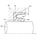
- FIG. 6 shows an example of a conventional dust seal 300.
- the dust seal 300 has a metal reinforcing ring in an annular gap between the housing 100 at the end of the cylinder in the hydraulic cylinder device and the shaft 200 inserted in the shaft hole 101 of the housing 100 so as to be reciprocally movable in the axial direction. 301 and a seal lip 302 are provided (see, for example, Patent Documents 1 and 2 below).
- the dust seal 300 includes a metal reinforcing ring 301 and a seal lip 302 formed integrally with the reinforcing ring 301 by a rubber elastic body (see, for example, Patent Documents 1 and 2 below).
- the outer peripheral surface of 200 is slidably in close contact.
- the seal lip 302 having a shape indicated by a broken line in the drawing is in close contact with the outer peripheral surface of the shaft 200 in a state where the diameter of the seal lip 302 has been appropriately expanded and deformed. A tightening margin necessary to prevent intrusion of muddy water and dust from the outer space on the right side in the drawing is given to the outer peripheral surface of 200.
- the seal lip 302 made of a rubber elastic body causes stress relaxation called “sagging” over time, and lowers the allowance for the outer peripheral surface of the shaft 200.
- a metal annular leaf spring 303 is mounted in the annular groove on the outer periphery of the seal lip 302, and the elastic force of the leaf spring 303 in the radial direction is used to tighten the seal lip 302.
- a dust seal 300 in which force is compensated (for example, see Patent Document 3 below).
- JP 2010-101490 A Japanese Patent Laying-Open No. 2015-232337 Japanese Patent Laying-Open No. 2015-135137
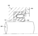
- the dust seal 300 shown in FIG. 7 when assembling the apparatus, the dust seal 300 is previously assembled in the seal mounting groove 102 formed in the outer end portion of the shaft hole 101 of the housing 100, and then the shaft 200 is inserted into the shaft hole 101.
- the seal when the shaft center 200 has an excessive eccentricity ⁇ O with respect to the shaft hole 101 of the housing 100, or when an excessive eccentricity ⁇ O is generated during use, the seal
- the leaf spring 303 undergoes deformation exceeding the elastic limit via the lip 302
- the radial urging force that compensates the tightening force of the seal lip 302 may be impaired due to plastic deformation as shown in FIG. .
- the technical problem of the present invention is to ensure excellent sealing performance by preventing plastic deformation of the leaf spring due to shaft eccentricity in a dust seal provided with a leaf spring that compensates the tight force of the seal lip.
- the dust seal of the present invention has a reinforcing ring that is held on the housing side, and a slidably close contact with an outer peripheral surface of a shaft that is provided on the reinforcing ring and whose tip is inserted into the shaft hole of the housing so as to be capable of reciprocating in the axial direction.
- a guide ring supported by a ring, and the guide ring holds the shaft concentrically with the reinforcing ring by inserting the shaft through an inner periphery.
- the reinforcing ring is attached to the housing side through the outer peripheral elastic body.
- the guide ring has, on its inner diameter portion, a scraper portion that protrudes outward in the axial direction and whose outer peripheral surface has a smaller diameter toward the outer side in the axial direction.
- the shaft is guided concentrically with the reinforcing ring of the dust seal by the guide ring of the dust seal in the process of inserting the shaft into the shaft hole of the housing after incorporating the dust seal in the housing in advance. Since it is held concentrically by the guide ring, there is no excessive eccentricity between the shaft and the reinforcing ring, so that the leaf spring may undergo excessive deformation via the seal lip and plastically deform. It is prevented and the tension of the seal lip is ensured by the leaf spring.
- the guide ring has a function of separating and removing the deposits on the outer peripheral surface of the shaft with the reciprocating motion of the shaft by being arranged on the outer side in the axial direction of the seal lip. Therefore, excellent sealing performance can be maintained.
- FIG. 2 is a half cross-sectional view showing a preferred embodiment of a dust seal according to the present invention cut along a plane passing through an axis together with a rod seal system using the dust seal. It is a half sectional view which cuts and shows the wearing state of a desirable embodiment of the dust seal concerning the present invention by the plane which passes along an axis.
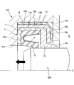
- FIG. 3 is a half sectional view showing a non-attached state of a preferred embodiment of the dust seal according to the present invention by cutting along a plane passing through an axis. In preferred embodiment of the dust seal which concerns on this invention, it is a half sectional view which cuts and shows the process which inserts an axis
- FIG. 6 is a half cross-sectional view showing a state where the shaft is eccentric in a mounted state of the preferred embodiment of the dust seal according to the present invention by cutting along a plane passing through the shaft center. It is a half sectional view of the wearing state which cuts and shows an example of the conventional dust seal in the plane which passes along an axis. It is a half sectional view of the wearing state which cuts and shows other examples of the conventional dust seal by the plane which passes along an axis. In another example of the conventional dust seal, it is a half sectional view showing a process of inserting a shaft by cutting along a plane passing through the axis. In the other example of the conventional dust seal, it is a half sectional view showing a state where the leaf spring is plastically deformed by cutting along a plane passing through the axis.
- FIG. 1 shows a state in which the dust seal 1 is used in a rod seal system of a hydraulic cylinder device.
- the rod seal system shown in FIG. 1 seals between a housing 100 provided at a cylinder end of a hydraulic cylinder device and a shaft 200 that is inserted through the shaft hole 101 of the housing 100 and reciprocates in the axial direction.
- the rod seal system includes a main seal 400 that prevents leakage of hydraulic oil in the hydraulic chamber A in the cylinder, and an oil pressure from the hydraulic chamber A that is disposed inside the main seal 400 (on the hydraulic chamber A side).
- a dust seal 1 which is disposed outside the main seal 400 in the axial direction and prevents intrusion of muddy water and dust from the external space B.
- the main seal 400, the buffer ring 500, and the dust seal 1 are respectively held in annular seal mounting grooves 102 formed at the outer ends of the shaft holes 101 of the housing 100.
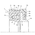
- the dust seal 1 is integrally fitted with each other, and is provided integrally with the reinforcing rings 11 and 12 held in the seal mounting groove 102 of the housing 100, and one of the reinforcing rings 11.
- a seal lip 13 slidably in contact with the outer peripheral surface of the plate, a leaf spring 14 for urging the seal lip 13 toward the outer peripheral surface of the shaft 200, and an outer diameter disposed outside the seal lip 13 in the axial direction.
- the guide ring 15 is sandwiched between the reinforcing rings 11 and 12, and the outer peripheral elastic body 16 is provided integrally with the reinforcing ring 12.
- One reinforcing ring 11 is made of metal. As shown in FIGS. 2 and 3, the reinforcing ring 11 includes a fitting tube portion 11 a and a flange portion 11 b extending from the end portion on the inner side in the axial direction of the fitting tube portion 11 a toward the inner diameter side.
- the shape (cross-sectional shape shown in the figure) cut by a plane passing through the axis is L-shaped.
- the other reinforcing ring 12 is made of the same metal as the reinforcing ring 11.
- the reinforcing ring 12 includes a fitting cylinder part 12a whose inner peripheral surface is fitted to the outer peripheral surface of the fitting cylinder part 11a of the reinforcement ring 11 with an appropriate tightening margin, and a shaft in a mounted state of the fitting cylinder part 12a.
- a shape having a flange portion 12b extending from the end on the outer side toward the inner diameter side and cut along a plane passing through the axial center forms an L-shape opposite to the reinforcing ring 11 in the axial direction.
- the seal lip 13 is made of a rubber elastic body (rubber material or synthetic resin material having rubber-like elasticity).
- the seal lip 13 is formed integrally with the reinforcing ring 11 at the outer peripheral base portion 13b.
- the outer peripheral base portion 13b is integrally joined to the inner peripheral surface of the fitting tube portion 11a of the reinforcing ring 11 and the inner side surface of the flange portion 11b, and the seal lip 13 is pivoted from the inner diameter portion of the outer peripheral base portion 13b.
- An end portion on the outside in the direction extends in a conical cylinder shape having a small diameter.
- the seal lip 13 has a lip tip 13a having an inner diameter whose shape cut in a plane passing through the shaft center forms a V-shape so as to be slidably in close contact with the outer peripheral surface of the shaft 200.
- the leaf spring 14 is made of an annular metal thin plate.
- the leaf spring 14 has a bent portion 14a, an inner peripheral spring portion 14b on the inner peripheral side, and an outer peripheral spring portion 14c on the outer peripheral side, and a shape cut along a plane passing through the axis forms a U shape.
- the leaf spring 14 includes a slit (not shown) that reaches the outer peripheral spring portion 14c side from the distal end of the inner peripheral spring portion 14b via the bent portion 14a, and an inner portion that extends from the distal end of the outer peripheral spring portion 14c via the bent portion 14a.
- Slits (not shown) that reach the peripheral spring portion 14b are alternately formed in the circumferential direction. Therefore, the leaf spring 14 extends in the circumferential direction while meandering in a zigzag manner in the axial direction by the slit, thereby enabling elastic bending deformation in the radial direction.
- the leaf spring 14 is fitted in an annular groove having a U-shaped cross section between the main body portion of the seal lip 13 and the outer peripheral base portion 13b.
- the leaf spring 14 In the mounted state between the housing 100 and the shaft 200 shown in FIGS. 1 and 2, the leaf spring 14 is appropriately bent and deformed in the radial direction via the seal lip 13 from the unmounted state shown in FIG. Due to the reaction force, the inner peripheral spring portion 14 b elastically biases the lip tip 13 a of the seal lip 13 in the inner diameter direction and compensates the tightening force of the seal lip 13 against the outer peripheral surface of the shaft 200.
- the guide ring 15 is made of a bearing material such as bronze, for example.
- the guide ring 15 includes an outward flange portion 15a and a scraper portion 15b that protrudes outward in the axial direction from an inner diameter end portion of the outward flange portion 15a and whose outer peripheral surface has a smaller diameter toward the outer side in the axial direction.
- the guide ring 15 has an outward flange portion 15a sandwiched between the fitting tube portion 11a of one reinforcing ring 11 and the flange portion 12b of the other reinforcing ring 12, thereby causing the reinforcing rings 11 and 12 to Built concentrically.
- the inner diameters of the outward flange portion 15a and the scraper portion 15b are formed such that the shaft 200 can be inserted with a minute gap, that is, slightly larger than the outer diameter of the shaft 200.
- the outer peripheral elastic body 16 is made of a rubber elastic body (rubber material or synthetic resin material having rubber-like elasticity) such as NBR (nitrile rubber) or H-NBR (hydrogenated nitrile rubber).
- the outer peripheral elastic body 16 is joined to the outer peripheral surface of the fitting tube portion 12a of the reinforcing ring 12, and the side elastic member joined to the outer surface of the flange portion 12b of the reinforcing ring 12 from the axially outer end portion thereof.
- the body 16a is extended.
- An annular recess 16b that reduces the compression reaction force of the outer peripheral elastic body 16 in the radial direction is formed at the axial intermediate portion of the outer peripheral surface of the outer peripheral elastic body 16. Even if the outer peripheral elastic body 16 is deformed in the radial direction due to the eccentricity of the housing 100 and the shaft 200, the outer peripheral surface of the outer peripheral elastic body 16 with respect to the inner peripheral surface of the seal mounting groove 102 is A seal protrusion 16c is formed for securing the pressure contact state.
- the reinforcing rings 11 and 12 are held in the seal mounting groove 102 of the housing 100 via the outer peripheral elastic body 16, and the plate 103 attached to the outer end of the housing 100 is the outer peripheral elastic body 16.
- the outer peripheral elastic body 16 is interposed between the fitting cylindrical portion 12a of the reinforcing ring 12 and the inner peripheral surface of the seal mounting groove 102 in a state of being appropriately compressed in the radial direction.
- the lip tip 13a of the seal lip 13 facing the external space B side is slidably in close contact with the outer peripheral surface of the shaft 200, so that muddy water and dust from the external space B are moved to the main seal 400 side shown in FIG. Prevent intrusion.
- the shaft 200 is connected to the guide ring 15. By passing through the inner circumference, it is guided concentrically with the reinforcing rings 11 and 12 held in the housing 100. Therefore, the shaft 200 is not greatly decentered with respect to the axis O of the reinforcing rings 11 and 12. The same applies to the state of use, and the shaft 200 is held concentrically with the reinforcing rings 11 and 12 by the guide ring 15, so that the shaft 200 may be greatly decentered with respect to the axis O of the reinforcing rings 11 and 12. Absent.
- the seal lip 13 is not greatly deformed in part in the circumferential direction due to the eccentricity of the shaft 200 with respect to the reinforcing rings 11, 12.
- the leaf spring 14 is subjected to deformation exceeding the elastic limit via the seal lip 13. There is no end. Therefore, the radial biasing force of the leaf spring 14 for compensating for the tension force of the seal lip 13 is not impaired.
Landscapes
- Engineering & Computer Science (AREA)
- General Engineering & Computer Science (AREA)
- Mechanical Engineering (AREA)
- Sealing With Elastic Sealing Lips (AREA)
- Sealing Devices (AREA)
Abstract
Description
11,12 補強環
13 シールリップ
14 板ばね
15 ガイドリング
15b スクレーパ部
16 外周弾性体
100 ハウジング
102 シール装着溝
200 軸
Claims (3)
- ハウジング側に保持される補強環と、
この補強環に設けられ、先端が前記ハウジングの軸孔に軸方向往復動可能に挿通された軸の外周面に摺動可能に密接されるシールリップと、
前記補強環の内周側に保持され、前記シールリップを前記軸の外周面に向けて付勢する板ばねと、
前記シールリップの軸方向外側に配置されると共に前記補強環に支持されたガイドリングと、
を備え、前記ガイドリングは、内周に前記軸が挿通されて前記軸を前記補強環と同心に保持する、ことを特徴とするダストシール。 - 補強環が外周弾性体を介してハウジング側に取り付けられることを特徴とする請求項1に記載のダストシール。
- ガイドリングの内径部に、軸方向外側へ突出し、外周面が軸方向外側へ向けて小径になるスクレーパ部が形成されたことを特徴とする請求項1又は2に記載のダストシール。
Priority Applications (5)
| Application Number | Priority Date | Filing Date | Title |
|---|---|---|---|
| KR1020187034659A KR20190005903A (ko) | 2016-05-10 | 2017-04-20 | 더스트 시일 |
| EP17795919.4A EP3457006A4 (en) | 2016-05-10 | 2017-04-20 | DUST SEAL |
| US16/300,344 US20190145519A1 (en) | 2016-05-10 | 2017-04-20 | Dust seal |
| JP2018516917A JP6629438B2 (ja) | 2016-05-10 | 2017-04-20 | ダストシール |
| CN201780026256.1A CN109073086B (zh) | 2016-05-10 | 2017-04-20 | 防尘密封件 |
Applications Claiming Priority (2)
| Application Number | Priority Date | Filing Date | Title |
|---|---|---|---|
| JP2016094400 | 2016-05-10 | ||
| JP2016-094400 | 2016-05-10 |
Publications (1)
| Publication Number | Publication Date |
|---|---|
| WO2017195558A1 true WO2017195558A1 (ja) | 2017-11-16 |
Family
ID=60267579
Family Applications (1)
| Application Number | Title | Priority Date | Filing Date |
|---|---|---|---|
| PCT/JP2017/015824 Ceased WO2017195558A1 (ja) | 2016-05-10 | 2017-04-20 | ダストシール |
Country Status (6)
| Country | Link |
|---|---|
| US (1) | US20190145519A1 (ja) |
| EP (1) | EP3457006A4 (ja) |
| JP (1) | JP6629438B2 (ja) |
| KR (1) | KR20190005903A (ja) |
| CN (1) | CN109073086B (ja) |
| WO (1) | WO2017195558A1 (ja) |
Families Citing this family (5)
| Publication number | Priority date | Publication date | Assignee | Title |
|---|---|---|---|---|
| KR102487835B1 (ko) | 2019-01-16 | 2023-01-12 | 주식회사 엘지에너지솔루션 | 충전 시간을 단축시킨 이차전지의 충전 방법 |
| CN111765246A (zh) * | 2019-03-26 | 2020-10-13 | 苏州三星电子有限公司 | 密封结构、洗衣机及加热器装配方法 |
| US20220205545A1 (en) * | 2020-12-31 | 2022-06-30 | Roger Zatkoff Company | Wiper-scraper with energizing spring |
| KR102451060B1 (ko) * | 2021-06-28 | 2022-10-07 | 디와이피엔에프 주식회사 | 고압 로터리씰을 가지는 로터리 밸브 |
| CN118140080A (zh) * | 2021-10-27 | 2024-06-04 | 美国圣戈班性能塑料公司 | 具有插入件的密封件及其制造和使用方法 |
Citations (7)
| Publication number | Priority date | Publication date | Assignee | Title |
|---|---|---|---|---|
| JPH01206166A (ja) * | 1988-02-12 | 1989-08-18 | Nissan Motor Co Ltd | すべり式ブッシュ用ダストシール素子 |
| JPH03108968U (ja) * | 1990-02-26 | 1991-11-08 | ||
| JP2005299619A (ja) * | 2004-04-13 | 2005-10-27 | Nok Corp | ポンプ用プランジャシール |
| JP2010101490A (ja) | 2008-09-26 | 2010-05-06 | Nok Corp | 密封構造 |
| JP2011247283A (ja) * | 2010-05-21 | 2011-12-08 | Nok Corp | シーリングシステム |
| JP2015135137A (ja) | 2014-01-16 | 2015-07-27 | Nok株式会社 | 密封装置 |
| JP2015232337A (ja) | 2014-06-09 | 2015-12-24 | Nok株式会社 | ダストシールによる密封構造 |
Family Cites Families (23)
| Publication number | Priority date | Publication date | Assignee | Title |
|---|---|---|---|---|
| US2867457A (en) * | 1954-07-16 | 1959-01-06 | Gen Motors Corp | Fluid seal |
| US3099454A (en) * | 1961-05-05 | 1963-07-30 | Victor Mfg & Gasket Co | Fluid seal |
| US3612547A (en) * | 1969-01-09 | 1971-10-12 | Nippon Seiko Kk | Lubricant seal having casing and its holding means |
| GB2066387B (en) * | 1979-12-21 | 1983-08-24 | Fenner Co Ltd J H | Shaft seals |
| US4300778A (en) * | 1980-02-07 | 1981-11-17 | International Packings Corporation | High pressure shaft seal |
| US4427206A (en) * | 1982-07-20 | 1984-01-24 | Keeper Co., Ltd. | Oil seal assembly with unbonded backup ring |
| DE3765249D1 (de) * | 1986-03-24 | 1990-10-31 | Zahnradfabrik Friedrichshafen | Dichtungring zur anordnung zwischen zueinander axial-und drehbeweglichen maschinenteilen. |
| BR9205265A (pt) * | 1992-04-30 | 1996-01-09 | Sabo Ind & Comercio Ltda | Retentor de água de tipo cartucho. |
| DE10000541A1 (de) * | 2000-01-08 | 2001-07-26 | Voith Paper Patent Gmbh | Dichtanordnung zwischen zwei relativ zueinander drehenden Bauteilen |
| DE10045393A1 (de) * | 2000-09-14 | 2002-03-28 | Roemheld A Gmbh & Co Kg | Abstreifkombination |
| GB0522220D0 (en) * | 2005-11-01 | 2005-12-07 | Ftl Seals Technology Ltd | Seal assembly and corresponding method for sealing |
| US8336887B2 (en) * | 2006-05-02 | 2012-12-25 | Petrak Gregory H | Seal assembly |
| CN102022545A (zh) * | 2009-09-22 | 2011-04-20 | 中国北方车辆研究所 | 一种组合式油气封 |
| CN202140575U (zh) * | 2011-07-04 | 2012-02-08 | 青岛开世密封工业有限公司 | 装配式油封 |
| CN102829185A (zh) * | 2012-09-24 | 2012-12-19 | 青岛开世密封工业有限公司 | 一种防止弹簧脱落的油封 |
| CN102996808B (zh) * | 2012-12-13 | 2015-05-13 | 青岛北海油封有限公司 | 防护油封 |
| DE102013000514B4 (de) * | 2013-01-15 | 2015-09-24 | Carl Freudenberg Kg | Dichtungsanordnung und deren Verwendung |
| CN203604653U (zh) * | 2013-11-22 | 2014-05-21 | 青岛开世密封工业有限公司 | 带有聚氨酯环的防泥水油封 |
| DE102014202796A1 (de) * | 2014-02-17 | 2015-08-20 | Robert Bosch Gmbh | Kolben-Kraftstoffpumpe für eine Brennkraftmaschine |
| US9869395B2 (en) * | 2014-02-26 | 2018-01-16 | Garlock Sealing Technologies, Llc | Shaft sealing apparatus and associated methods |
| DE102014210129A1 (de) * | 2014-05-27 | 2015-12-03 | Aktiebolaget Skf | Dichtungsvorrichtung und Verfahren zum Abdichten in einem flüssigen Medium |
| WO2016055250A1 (en) * | 2014-10-09 | 2016-04-14 | Robert Bosch Gmbh | Pump for supplying fuel at high pressure to an internal combustion engine |
| CN108328245B (zh) * | 2017-01-18 | 2021-06-15 | 斯凯孚公司 | 用于连铸机的密封盒 |
-
2017
- 2017-04-20 EP EP17795919.4A patent/EP3457006A4/en not_active Withdrawn
- 2017-04-20 US US16/300,344 patent/US20190145519A1/en not_active Abandoned
- 2017-04-20 WO PCT/JP2017/015824 patent/WO2017195558A1/ja not_active Ceased
- 2017-04-20 CN CN201780026256.1A patent/CN109073086B/zh not_active Expired - Fee Related
- 2017-04-20 KR KR1020187034659A patent/KR20190005903A/ko not_active Ceased
- 2017-04-20 JP JP2018516917A patent/JP6629438B2/ja active Active
Patent Citations (7)
| Publication number | Priority date | Publication date | Assignee | Title |
|---|---|---|---|---|
| JPH01206166A (ja) * | 1988-02-12 | 1989-08-18 | Nissan Motor Co Ltd | すべり式ブッシュ用ダストシール素子 |
| JPH03108968U (ja) * | 1990-02-26 | 1991-11-08 | ||
| JP2005299619A (ja) * | 2004-04-13 | 2005-10-27 | Nok Corp | ポンプ用プランジャシール |
| JP2010101490A (ja) | 2008-09-26 | 2010-05-06 | Nok Corp | 密封構造 |
| JP2011247283A (ja) * | 2010-05-21 | 2011-12-08 | Nok Corp | シーリングシステム |
| JP2015135137A (ja) | 2014-01-16 | 2015-07-27 | Nok株式会社 | 密封装置 |
| JP2015232337A (ja) | 2014-06-09 | 2015-12-24 | Nok株式会社 | ダストシールによる密封構造 |
Non-Patent Citations (1)
| Title |
|---|
| See also references of EP3457006A4 |
Also Published As
| Publication number | Publication date |
|---|---|
| EP3457006A1 (en) | 2019-03-20 |
| US20190145519A1 (en) | 2019-05-16 |
| EP3457006A4 (en) | 2019-05-15 |
| CN109073086B (zh) | 2020-01-14 |
| JP6629438B2 (ja) | 2020-01-15 |
| JPWO2017195558A1 (ja) | 2019-03-07 |
| KR20190005903A (ko) | 2019-01-16 |
| CN109073086A (zh) | 2018-12-21 |
Similar Documents
| Publication | Publication Date | Title |
|---|---|---|
| JP6629438B2 (ja) | ダストシール | |
| US6149158A (en) | Unitized oil seal with PTFE sealing disk split at radially outer edge and method of manufacture | |
| JP7014815B2 (ja) | シール組立体 | |
| JP5216084B2 (ja) | リップタイプシール | |
| JP2007321760A (ja) | 遠心ポンプ用、詳細には内燃機関の冷却液ポンプ用低摩擦の環状密閉アセンブリ | |
| JP2008309263A (ja) | 密封装置 | |
| JP6405389B2 (ja) | 密封装置 | |
| JP2010242874A (ja) | 往復動用密封装置 | |
| JP4952913B2 (ja) | ウォーターポンプ用密封装置 | |
| JP6991943B2 (ja) | 分割型メカニカルシール | |
| JP2010242814A (ja) | 密封装置 | |
| WO2019230238A1 (ja) | シールリング及び密封構造 | |
| JP2017048871A (ja) | 密封装置 | |
| JP5344163B2 (ja) | 密封装置 | |
| JP2007107550A (ja) | 往復動軸用密封装置 | |
| US20150001804A1 (en) | Fluid seal assembly with wear ring | |
| JP5617658B2 (ja) | 密封装置 | |
| JP2019100359A (ja) | 密封装置 | |
| JP2007247708A (ja) | 軸付きシール | |
| JP2015232337A (ja) | ダストシールによる密封構造 | |
| CN113994127B (zh) | 密封装置 | |
| JP2005273693A (ja) | 密封装置 | |
| JP2024080154A (ja) | ダストシール | |
| JP2017166597A (ja) | 密封構造および密封装置 | |
| JP2017150590A (ja) | 密封装置 |
Legal Events
| Date | Code | Title | Description |
|---|---|---|---|
| ENP | Entry into the national phase |
Ref document number: 2018516917 Country of ref document: JP Kind code of ref document: A |
|
| NENP | Non-entry into the national phase |
Ref country code: DE |
|
| 121 | Ep: the epo has been informed by wipo that ep was designated in this application |
Ref document number: 17795919 Country of ref document: EP Kind code of ref document: A1 |
|
| ENP | Entry into the national phase |
Ref document number: 20187034659 Country of ref document: KR Kind code of ref document: A |
|
| ENP | Entry into the national phase |
Ref document number: 2017795919 Country of ref document: EP Effective date: 20181210 |