WO2017195815A1 - 基地局装置、端末装置およびその通信方法 - Google Patents
基地局装置、端末装置およびその通信方法 Download PDFInfo
- Publication number
- WO2017195815A1 WO2017195815A1 PCT/JP2017/017662 JP2017017662W WO2017195815A1 WO 2017195815 A1 WO2017195815 A1 WO 2017195815A1 JP 2017017662 W JP2017017662 W JP 2017017662W WO 2017195815 A1 WO2017195815 A1 WO 2017195815A1
- Authority
- WO
- WIPO (PCT)
- Prior art keywords
- contention
- transmission
- base station
- subframe
- base
- Prior art date
- Legal status (The legal status is an assumption and is not a legal conclusion. Google has not performed a legal analysis and makes no representation as to the accuracy of the status listed.)
- Ceased
Links
Images


Classifications
-
- H—ELECTRICITY
- H04—ELECTRIC COMMUNICATION TECHNIQUE
- H04W—WIRELESS COMMUNICATION NETWORKS
- H04W74/00—Wireless channel access
- H04W74/02—Hybrid access
-
- H—ELECTRICITY
- H04—ELECTRIC COMMUNICATION TECHNIQUE
- H04W—WIRELESS COMMUNICATION NETWORKS
- H04W72/00—Local resource management
- H04W72/20—Control channels or signalling for resource management
- H04W72/21—Control channels or signalling for resource management in the uplink direction of a wireless link, i.e. towards the network
-
- H—ELECTRICITY
- H04—ELECTRIC COMMUNICATION TECHNIQUE
- H04W—WIRELESS COMMUNICATION NETWORKS
- H04W72/00—Local resource management
- H04W72/20—Control channels or signalling for resource management
- H04W72/23—Control channels or signalling for resource management in the downlink direction of a wireless link, i.e. towards a terminal
-
- H—ELECTRICITY
- H04—ELECTRIC COMMUNICATION TECHNIQUE
- H04W—WIRELESS COMMUNICATION NETWORKS
- H04W76/00—Connection management
- H04W76/20—Manipulation of established connections
- H04W76/27—Transitions between radio resource control [RRC] states
-
- H—ELECTRICITY
- H04—ELECTRIC COMMUNICATION TECHNIQUE
- H04W—WIRELESS COMMUNICATION NETWORKS
- H04W72/00—Local resource management
- H04W72/12—Wireless traffic scheduling
-
- H—ELECTRICITY
- H04—ELECTRIC COMMUNICATION TECHNIQUE
- H04W—WIRELESS COMMUNICATION NETWORKS
- H04W74/00—Wireless channel access
- H04W74/08—Non-scheduled access, e.g. ALOHA
Definitions
- the present invention relates to a base station device, a terminal device, and a communication method thereof.
- terminal devices In communication systems such as LTE (Long Term Evolution) and LTE-A (LTE-Advanced) specified in 3GPP (Third Generation Partnership Project), terminal devices (UE: User Equipment) transmit data to the uplink buffer.
- a scheduling request (SR: SRScheduling Request) and a buffer status report (BSR: Buffer Status Report) are transmitted to the base station device (eNodeB: evolved Node B).
- the terminal apparatus After that, when receiving the uplink transmission permission (UL Grant) control information from the base station apparatus, the terminal apparatus transmits data using predetermined radio resources based on the uplink transmission parameters included in the UL Grant. In this way, the base station apparatus controls radio resources for all uplink data transmission (data transmission from the terminal apparatus to the base station apparatus).
- the base station apparatus controls uplink radio resources, thereby realizing orthogonal multiple access (OMA: Orthogonal Multiple Access).
- OMA Orthogonal Multiple Access
- Non-Patent Document 1 Non-Patent Document 2
- a terminal device transmits and receives control information before transmitting uplink data regardless of the data size to be transmitted.
- the proportion of overhead such as control information becomes relatively high.
- Non-Patent Document 3 There is a contention-based wireless communication technology (Non-Patent Document 3) as a method for suppressing an increase in overhead due to control information.
- a terminal device transmits uplink data in contention-based wireless communication, data transmitted by a plurality of terminal devices at the same time and at the same frequency collide, and data from the terminal devices exceeding the number of receiving antennas of the base station device Is non-orthogonal multiplexed.
- a base station device that supports contention-based wireless communication technology detects transmission data signals by applying turbo equalization, successive interference canceller (SIC) and SLIC (Symbol Level Interference Canceller). It is possible. Thereby, the terminal device can communicate without performing transmission of SR and reception of UL Grant. Furthermore, the contention-based wireless communication technology can shorten the time from transmission data generation to transmission.
- SIC successive interference canceller
- SLIC Symbol Level Interference Canceller
- terminal devices that support non-orthogonal multiple access (NOMA: Non- Orthogonal Multiple ⁇ ⁇ ⁇ Access) realized by contention-based wireless communication technology and terminal devices that do not support (terminal devices that support only the OMA) can be mixed.
- NOMA Non- Orthogonal Multiple ⁇ ⁇ ⁇ Access
- terminal devices that do not support terminal devices that support only the OMA
- the communication quality of the uplink transmission data based on OMA may deteriorate.
- the terminal device may not be able to detect the uplink transmission data based on NOMA, and the desired communication The quality may not be maintained.
- the present invention has been made in view of such circumstances, and an object of the present invention is to mix uplink data transmission based on OMA and uplink data transmission based on NOMA in a cell in which a large number of terminal devices exist. It is an object of the present invention to provide a base station device, a terminal device, and a communication method capable of maintaining these uplink data at a predetermined communication quality.
- the configurations of the base station apparatus, terminal apparatus, and communication method according to the present invention are as follows.
- One aspect of the present invention is a base station device that communicates with a terminal device that supports contention-based access and non-contention-based access, and includes an arrangement of contention-based access regions and non-contention-based access regions.
- An upper layer processing unit configured to indicate, a transmission unit configured to transmit radio frame format setting information indicating an arrangement of the contention base access region and the non-contention base access region, the contention base access region and the non-contention
- a reception unit that receives an uplink data channel based on a radio frame format configured by a tension base access region, and the uplink data channel that receives a non-contention base is the contention base access region
- the transmission unit transmits a contention-based transmission setting change notification indicating that a subframe that receives the uplink data channel is changed to a subframe that performs non-contention-based transmission. It is characterized by.
- one aspect of the present invention is characterized in that the contention-based transmission setting change notification is a contention-based access prohibition notification for a subframe that receives the uplink data channel.
- One aspect of the present invention is characterized in that the contention-based transmission setting change notification is broadcast to a terminal device connected to the base station device.
- one aspect of the present invention is characterized in that the transmission unit transmits the contention-based transmission setting change notification using downlink control information.
- the radio frame format includes a contention base access region and a non-contention base access region that are frequency division multiplexed, and an uplink data channel to be transmitted on a non-contention basis is Transmitting a contention-based transmission setting change notification for a subframe that receives the uplink data channel when it occurs over the frequency band of the contention-based access region and the frequency band of the non-contention-based access region.
- the receiving unit receives an uplink control channel including uplink control information
- the upper layer processing unit is configured such that the uplink control channel includes the contention-based access.
- the uplink control channel is a subframe including the contention base access region. It is set to receive.
- the uplink control channel is the next of a subframe including the contention base access region. It is set to receive in the non-contention base access area arranged in the network.
- One aspect of the present invention is a notification method of a base station apparatus that communicates with a terminal apparatus that supports contention-based access and non-contention-based access, wherein the contention-based access area and the non-contention-based access area A setting indicating the arrangement of the contention base, a step of transmitting radio frame format setting information indicating the arrangement of the contention base access area and the non-contention base access area, the contention base access area and the non-contention Receiving an uplink data channel based on a radio frame format configured in a base access region, wherein the uplink data channel received on a non-contention basis is the contention base address.
- the transmission unit When the transmission unit generates a subframe including an access region, the transmission unit sends a contention-based transmission setting change notification indicating that the subframe that receives the uplink data channel is changed to a subframe that performs non-contention-based transmission. Transmitting.
- One aspect of the present invention is a terminal apparatus that communicates with a base station apparatus that supports contention-based access and non-contention-based access, and the arrangement of the contention-based access area and the non-contention-based access area
- a receiving unit that receives radio frame format setting information indicating, and a transmitting unit that transmits an uplink data channel based on a radio frame format configured by the contention base access region and the non-contention base access region
- the contention-based transmission setting change notification indicates that the subframe is to be changed to a non-contention-based transmission
- the receiver receives contention for a contention-based access area included in the radio frame format.
- the subframe indicated by the contention-based transmission setting change notification is a contention-based access area or a non-contention-based uplink regardless of the non-contention-based access area. Transmitting a data channel.
- One aspect of the present invention is a communication method for a terminal device that communicates with a base station device that supports contention-based access and non-contention-based access, wherein the contention-based access region and the non-contention-based access
- the contention-based transmission setting change notification indicates that the content is changed to a subframe in which non-contention-based transmission is performed, and the terminal device enters the contention-based access area included in the radio frame format. If the subframe indicated by the contention-based transmission setting change notification is a contention-based access area or a non-contention-based access area, Transmitting an uplink data channel.
- the uplink data is transferred to a predetermined communication quality. Can be maintained.
- the communication system includes a base station device (transmitting device, cell, small cell, serving cell, transmission point, transmitting antenna group, transmitting antenna port group, component carrier, eNodeB, Home eNodeB) and terminal device (terminal, mobile Terminal, receiving point, receiving terminal, receiving device, receiving antenna group, receiving antenna port group, UE).
- the communication system is not limited to data communication between a terminal device and a base station device with human intervention, but MTC (Machine Type Communication), M2M communication (Machine-to-Machine Communication), and IoT (Internet of Things). ) Communication, NB-IoT (Narrow Band-IoT), etc.
- MTC mobile transmission
- the terminal device is an MTC terminal.
- the communication system can also be applied to D2D (Device-to-Device) communication.
- D2D Device-to-Device
- both the transmitting device and the receiving device are terminal devices.
- DFTS-OFDM Discrete Fourier Transform Spread-Orthogonal Frequency Division Multiplexing, also referred to as SC-FDMA
- SC-FDMA Discrete Fourier Transform Spread-Orthogonal Frequency Division Multiplexing
- OFDM modulation is used for the downlink.
- SC-FDMA Discrete Fourier Transform Spread-Orthogonal Frequency Division Multiplexing
- the base station apparatus and the terminal apparatus in the present embodiment are a frequency band called a licensed band (licensed band) obtained from a country or region where a wireless provider provides a service (license), and / or Communication is possible in a so-called unlicensed band that does not require a license from the country or region.
- a licensed band obtained from a country or region where a wireless provider provides a service (license)
- / or Communication is possible in a so-called unlicensed band that does not require a license from the country or region.
- X / Y includes the meaning of “X or Y”. In the present embodiment, “X / Y” includes the meanings of “X and Y”. In the present embodiment, “X / Y” includes the meaning of “X and / or Y”.
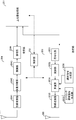
- FIG. 1 is a diagram illustrating an example of a communication system according to the present embodiment.
- the communication system in this embodiment includes a base station device 10, terminal devices 20-1 to 20-n, and terminal devices 30-1 to 30-m (n and m are natural numbers).
- the terminal devices 20-1 to 20-n are also collectively referred to as the terminal device 20.
- the terminal devices 30-1 to 30-m are also collectively referred to as the terminal device 30.
- the coverage 10a is a range (communication area) in which the base station device 10 can connect to the terminal devices 20 and 30 (also referred to as a cell).
- the terminal device 20 supports non-contention based multiple access (non-contention based multiple access).
- the terminal device 20 transmits uplink data based on the uplink transmission permission (UL Grant) received from the base station device 10 (non-contention based access or scheduled access). Also called data transmission).
- uplink data signals transmitted by a terminal apparatus are orthogonal (uplink orthogonal multiple) in time / frequency / space (eg, antenna port, beam pattern, precoding pattern) resources. Also called connection). In this case, it is preferable that the total number of transmission antennas of the terminal device 20 that has transmitted uplink data at the same time and the same frequency is equal to or less than the number of reception antennas of the base station device 10.
- the terminal device 30 supports at least contention-based multiple access (contention-based multiple access).
- contention-based multiple access the terminal device 30 transmits uplink data regardless of reception of UL Grant from the base station device 10 (also referred to as data transmission for contention-based access, grant-free access, or grant-less access).
- uplink data transmitted by the terminal device 30 is allowed to overlap in time / frequency / space resources (uplink non-orthogonal multiple access (UL-NOMA: UpLink Non Orthogonal Also called Multiple Access)).
- UL-NOMA UpLink Non Orthogonal Also called Multiple Access
- the terminal device 30 transmits uplink data at the same time and at the same frequency, uplink data signals transmitted from the terminal device exceeding the number of receiving antennas of the base station device are spatially transmitted. Non-orthogonal multiplexed. Note that the terminal device 30 can also apply both non-contention based multiple access and contention based multiple access. Which multiple access is applied may be set in the UE category of the terminal device 30. The UE category is determined by the maximum number of transport blocks received from the terminal device, the modulation scheme supported by the terminal device, the number of layers supported by the terminal device, or the like.
- the base station apparatus 10 detects a non-orthogonal multiplexed uplink data signal.
- the base station apparatus 10 uses SLIC (Symbol Level Interference Cancellation) for canceling interference based on the demodulation result of the interference signal, and CWIC (Codeword Level Interference for canceling interference based on the decoding result of the interference signal.
- Cancellation turbo equalization
- maximum likelihood detection ML: maximum likelihood, R-ML: Reduced complexity maximum likelihood
- EMMSE-IRC that suppresses interference signals by linear operation (Enhanced-Minimum-Mean-Square-Error-Interference-Rejection-Combining) may be provided.
- the uplink physical channel is used for transmitting information output from an upper layer.
- ⁇ Physical uplink control channel (PUCCH) Physical Uplink Shared Channel (PUSCH) ⁇ Physical Random Access Channel (PRACH)
- PUCCH Physical uplink control channel
- PUSCH Physical Uplink Shared Channel
- PRACH Physical Random Access Channel
- the PUCCH is used to transmit uplink control information (UCI: “Uplink Control” information).
- UCI Uplink Control
- a plurality of UCI formats are defined for transmission of uplink control information. That is, fields for uplink control information are defined in the UCI format and mapped to information bits.
- the uplink control information includes ACK (a positive acknowledgment) or NACK (ac negative acknowledgment) (ACK / NACK) for downlink data (downlink transport block, DL-SCH: Downlink-Shared Channel).
- ACK / NACK is also referred to as HARQ-ACK and HARQ feedback.
- the uplink control information includes a scheduling request (SR: “Scheduling” Request).
- the SR is a message for requesting transmission of UL Grant in order to transmit uplink data (for example, PUSCH).
- the uplink control information includes channel state information (CSI: “Channel State Information”) for the downlink.
- the channel state information includes a rank index (RI: Rank Indicator) that designates a suitable spatial multiplexing number, a precoding matrix indicator (PMI: Precoding Matrix Indicator) that designates a suitable precoder, and a channel quality that designates a suitable transmission rate.
- RI rank index
- PMI Precoding Matrix Indicator
- CQI “Channel Quality” Indicator
- the channel quality indicator CQI (hereinafter referred to as CQI value) can be a suitable modulation scheme (for example, QPSK, 16QAM, 64QAM, 256QAM, etc.) and a coding rate in a predetermined band.
- the CQI value can be an index (CQI Index) determined by the modulation scheme and coding rate.
- the CQI value can be predetermined by the system.
- the rank index and the precoding quality index can be determined in advance by the system.
- the rank index and the precoding matrix index can be indexes determined by the spatial multiplexing number and precoding matrix information.
- the values of the rank index, the precoding matrix index, and the channel quality index CQI are collectively referred to as CSI values.
- the PUCCH format is associated with a combination of ACK / NACK, CSI, and SR.
- a PUCCH format including only SR is defined as uplink control information.
- a PUCCH format including CSI is defined.
- a PUCCH format including ACK / NACK is defined as uplink control information.
- the PUCCH format including ACK / NACK is defined according to the number of component carriers in carrier aggregation.
- the PUCCH format including ACK / NACK is defined according to the number of spatial multiplexing.
- As uplink control information a PUCCH format including ACK / NACK and CSI is defined.
- a PUCCH format including ACK / NACK and SR is defined.
- a PUCCH format including CSI and SR is defined as uplink control information.
- uplink control information a PUCCH format including ACK / NACK, CSI, and SR is defined.
- the PUCCH format can be defined only in the case of non-contention based multiple access wireless communication. That is, PUCCH is not transmitted in contention-based multiple access wireless communication.
- the communication system in the present embodiment can also associate the PUCCH format with non-contention based / contention based multiple access (orthogonal multiple access / non-orthogonal multiple access).
- a PUCCH format including SR in non-contention base is defined separately from a format including SR in contention base.
- the PUCCH format including ACK / NACK in the non-contention base is defined separately from the format including ACK / NACK in the contention base.
- the PUCCH format including CSI in non-contention base is defined separately from the format including CSI in contention base.
- the PUCCH may be generated by adding a cyclic redundancy check (CRC: “Cyclic Redundancy Check”) to the uplink control information. Further, in the PUCCH, the uplink control information / CRC may be scrambled (exclusive OR operation) using a predetermined identification signal. For example, in PUCCH for contention-based multiple access wireless communication, uplink control information / CRC is scrambled using a cell radio network temporary identifier (C-RNTI: “Cell- Radio Network Temporary Identifier) as an identification signal.
- C-RNTI Cell- Radio Network Temporary Identifier
- the identification signal is a signal for the base station apparatus 10 to identify each of the terminal apparatuses 20 and 30.
- the PUSCH is used for transmitting uplink data (uplink transport block, UL-SCH).
- PUSCH is transmitted on a contention basis / non-contention basis.
- the PUSCH may be used to transmit ACK / NACK and / or channel state information.
- the PUSCH may be used to transmit uplink control information.
- the PUSCH is used to transmit a radio resource control (RRC: “Radio” Resource “Control”) message.
- RRC radio resource control
- the RRC message is information / signal processed in the radio resource control layer.
- PUSCH is used to transmit MAC CE (Control Element).
- the MAC CE is information / signal processed (transmitted) in the medium access control (MAC) layer.
- the power headroom may be included in the MAC CE and reported via PUSCH. That is, the MAC CE field is used to indicate the power headroom level.
- the uplink data includes an RRC message and MAC CE.
- the PUSCH may be generated by adding a cyclic redundancy check (CRC: “Cyclic Redundancy Check”) to the uplink data.
- CRC Cyclic Redundancy Check
- the ACK / NACK and / or channel state information may be included.
- the uplink data / CRC may be scrambled (exclusive OR operation) using a predetermined identification signal.
- uplink data / CRC is scrambled using a cell radio network temporary identifier (C-RNTI: “Cell- Radio” Network Temporary Identifier) as an identification signal.
- C-RNTI may be an identifier unique to contention-based multiple access wireless communication that is distinguished from non-contention based multiple access wireless communication.
- the identification signal can be determined in the same manner as the PUCCH.
- the terminal device receives ACK / NACK for the uplink data.
- the terminal apparatus retransmits the uplink data itself or data related to the uplink data.
- the terminal apparatus may retransmit data related to the uplink data on a contention basis. In this case, the terminal apparatus retransmits using the resources allocated for the contention base in the DCI format.
- the terminal device 30 may determine whether the uplink data is non-contention based transmission or contention based transmission according to service quality (Qos: Quality of Service) and an application in which the data is used.
- Qos Quality of Service
- Qos Quality of Service
- the terminal device 30 may determine whether uplink data is non-contention based transmission or contention based transmission according to the amount of data (number of transmission bits). For example, when transmitting uplink data composed of packets with a threshold value of x bits or less, the terminal device 30 can transmit the uplink data in a contention basis.
- the base station apparatus 10 can set the threshold value x.
- the terminal device 30 may determine whether uplink data is non-contention based transmission or contention based transmission according to the transmission mode.
- PRACH is used to transmit a random access preamble.
- an uplink reference signal (Uplink Signal: UL RS) is used as an uplink physical signal.
- the uplink physical signal is not used for transmitting information output from the upper layer, but is used by the physical layer.
- the uplink reference signal includes DMRS (Demodulation Reference Signal) and SRS (Sounding Reference Signal).
- DMRS is related to transmission of PUSCH or PUCCH.
- the base station apparatus 10 uses DMRS to perform channel correction when demodulating PUSCH or PUCCH.
- SRS is not related to PUSCH or PUCCH transmission.
- the base station apparatus 10 uses SRS to measure the uplink channel state.
- the downlink physical channel is used for transmitting information output from an upper layer.
- PBCH Physical Broadcast Channel
- PCFICH Physical Control Format Indicator Channel
- PHICH Physical hybrid automatic repeat request indicator channel
- PDCCH Physical downlink control channel
- PDSCH Physical downlink shared channel
- the PBCH is used to broadcast a master information block (Master Information Block: MIB, Broadcast Channel: BCH) that is commonly used by terminal devices.
- the PBCH includes information such as a system band, a system frame number (SFN: System Frame number), and the number of transmission antennas used by the eNB.
- PCFICH is used for transmitting information indicating a region (for example, the number of OFDM symbols) used for transmission of PDCCH.
- PHICH is used to transmit ACK / NACK for uplink data (transport block, codeword) received by the base station apparatus. That is, PHICH is used to transmit a HARQ indicator (HARQ feedback) indicating ACK / NACK for uplink data.
- the terminal device notifies the received ACK / NACK to the upper layer.
- the ACK / NACK includes ACK indicating that the data has been correctly received, NACK indicating that the data has not been correctly received, and DTX indicating that there is no corresponding data. Further, when there is no PHICH for uplink data, the terminal apparatus notifies ACK to an upper layer.
- ACK / NACK transmission may be applicable only to non-contention based multiple access wireless communication. That is, ACK / NACK is not transmitted for PUSCH transmitted on a contention basis. In this case, PHICH is not transmitted for PUSCH transmitted on a contention basis. Note that the retransmission may be applied only to the non-contention base (the retransmission is not applied to the contention base).
- PDCCH and EPDCCH are used to transmit downlink control information (DCI: “Downlink” Control “Information”).
- DCI Downlink control information
- a plurality of DCI formats are defined for transmission of downlink control information. That is, fields for downlink control information are defined in the DCI format and mapped to information bits.
- the DCI format includes control information for downlink data transmission and control information for uplink data transmission.
- a DCI format 1A used for scheduling one PDSCH (transmission of one downlink transport block) in one cell is defined as a DCI format for downlink data transmission.
- the DCI format for downlink data transmission includes information on PDSCH resource allocation, information on MCS (Modulation & Coding Scheme) for PDSCH, and downlink control information such as TPC command for PUCCH.
- a DCI format for downlink data transmission is also referred to as a downlink grant (or downlink assignment).
- DCI format 0 used for scheduling one PUSCH (transmission of one uplink transport block) in one cell is defined as a DCI format for uplink data transmission.
- the DCI format for uplink data transmission includes information on PUSCH resource allocation, information on MCS for PUSCH, information on RV (Redundancy Version) for PUSCH, information on cyclic shift for DMRS, TPC command for PUSCH, etc. Uplink control information is included.
- the DCI format for the uplink is also referred to as an uplink grant (or uplink assignment).
- the DCI format for uplink data transmission can be used to request downlink channel state information (CSI: “Channel State Information”, also referred to as reception quality information).
- the channel state information includes a rank indicator (RI: Rank Indicator) that specifies a suitable spatial multiplexing number, a precoding matrix indicator (PMI: Precoding Matrix Indicator) that specifies a suitable precoder, and a channel quality index that specifies a suitable transmission rate.
- RI Rank Indicator
- PMI Precoding Matrix Indicator
- CQI Channel Quality Indicator
- precoding type indicator PTI: Precoding type Indicator
- the DCI format for uplink data transmission can be used for setting indicating an uplink resource for mapping a channel state information report (CSI feedback ⁇ report) that the terminal device feeds back to the base station device.
- the channel state information report can be used for setting indicating an uplink resource that periodically reports channel state information (Periodic CSI).
- the channel state information report can be used for mode setting (CSI report mode) for periodically reporting the channel state information.
- the channel state information report can be used for setting indicating an uplink resource for reporting irregular channel state information (Aperiodic CSI).
- the channel state information report can be used for mode setting (CSI report mode) for reporting the channel state information irregularly.
- the base station apparatus can set the periodic channel state information report or the irregular channel state information report.
- the base station apparatus can set both the periodic channel state information report and the irregular channel state information report.
- the DCI format for uplink data transmission can be used for setting indicating the type of channel state information report that the terminal apparatus feeds back to the base station apparatus.
- Types of channel state information reports include wideband CSI (for example, Wideband CQI) and narrowband CSI (for example, Subband CQI).
- the terminal apparatus receives the downlink data on the scheduled PDSCH.
- a terminal device that supports non-contention-based uplink transmission uses the scheduled PUSCH / PUCCH logical resource to transmit uplink data and / or uplink data.
- Link control information can be transmitted.
- the DCI format for uplink data transmission can include a downlink assignment index (DAI: Downlink Assignment Index).
- DAI Downlink Assignment Index
- the DAI is used for uplink and downlink settings in a time division multiplexing (TDD: “Time Division” Duplex) frame.
- the DCI format for uplink data transmission can be used to set an area for non-contention based transmission and an area for contention based transmission (hereinafter, non-contention base-contention base setting). Called).
- the non-contention base-contention base setting can be set in units of subframes.
- Non-contention base-contention base settings can be set on a slot basis.
- the non-contention base-contention base setting can be set for each symbol (refer to FIG. 7 for definitions of radio frames, subframes, and symbols).
- the non-contention base-contention base setting can be included in the DAI.
- Non-contention based-contention based configuration may also be included in the DCI format for downlink data transmission.
- the PDCCH is generated by adding a cyclic redundancy check (CRC: “Cyclic Redundancy Check”) to the downlink control information.
- CRC Cyclic Redundancy Check
- downlink control information / CRC is scrambled (exclusive OR operation) using a predetermined identification signal.
- the uplink control information / CRC is scrambled using a cell radio network temporary identifier (C-RNTI: “Cell- Radio” Network Temporary Identifier) as an identification signal.
- C-RNTI cell radio network temporary identifier
- an identifier unique to contention-based wireless communication that is distinguished from non-contention-based wireless communication may be defined.
- the identification signal may be associated with a signal for identifying a terminal device that transmits contention based or an uplink data signal (for example, PUSCH) that is transmitted based on contention.
- a DCI format for contention-based transmission may be defined.
- the DCI format for contention-based transmission may be scrambled with an identifier unique to contention-based wireless communication.
- the DCI format for contention based transmission is used to notify control information for contention based transmission.
- the DCI format for contention-based transmission includes the contention base such as the non-contention base-contention base setting and the contention-based transmission possible period (subframe interval, slot interval, frame interval, etc.) Control information for transmission is included.
- PDSCH is used to transmit downlink data (downlink transport block, DL-SCH).
- PDSCH is used to transmit a system information block type 1 message.
- the system information block type 1 message is cell specific (cell specific) information.
- the PDSCH is used to transmit a system information message.
- the system information message includes a system information block X other than the system information block type 1.
- the system information message is cell specific (cell specific) information.
- the system information message may include a system information block specific to contention-based transmission.
- a system information block specific to contention-based transmission includes control information for contention-based transmission such as the non-contention base-contention base setting and a period in which contention-based transmission is possible. Part or all of the system information message can be included in the RRC message.
- the PDSCH is used to transmit an RRC message.
- the RRC message may include a message for contention-based transmission control information.
- the RRC message transmitted from the base station apparatus may be common (cell specific) to a plurality of terminal apparatuses in the cell. That is, information common to user apparatuses in the cell is transmitted using a cell-specific RRC message.
- the RRC message transmitted from the base station device may be a message dedicated to a certain terminal device (also referred to as dedicated signaling). That is, user device specific (user device specific) information is transmitted to a certain terminal device using a dedicated message.
- the RRC message transmitted from the base station apparatus may be a message dedicated to contention base transmission. That is, information specific to contention-based transmission may be transmitted using a message dedicated to contention-based transmission.
- PDSCH is used to transmit MAC CE.
- the RRC message and / or MAC CE is also referred to as higher layer signaling.
- the PDSCH can be used to request downlink channel state information.
- the PDSCH can be used to transmit an uplink resource that maps a channel state information report (CSI feedback report) that the terminal device feeds back to the base station device.
- CSI feedback report a channel state information report
- the channel state information report can be used for setting indicating an uplink resource for reporting periodic channel state information (Periodic CSI) / aperiodic channel state information (Aperiodic CSI).
- the channel state information report can be used for mode setting (CSI report mode) for reporting the channel state information regularly / irregularly.
- the types of downlink channel state information reports include wideband CSI (for example, Wideband CSI) and narrowband CSI (for example, Subband CSI).
- the broadband CSI calculates one channel state information for the system band of the cell.
- the narrowband CSI the system band is divided into predetermined units, and one channel state information is calculated for the division.
- the communication system can define a contention-based dedicated physical channel.
- the contention-based dedicated physical channel is used to transmit control information specific to contention-based transmission generated by an upper layer signal.
- the contention-based dedicated physical channel transmits control information for contention-based transmission such as the non-contention base-contention base setting and a period in which contention-based transmission is possible.
- the contention-based dedicated physical channel can be periodically transmitted in a predetermined subframe in the downlink radio resource format.
- the contention-based dedicated physical channel can be read in common (cell-specific) by the terminal devices connected to the cell 10a.
- the contention-based dedicated physical channel may be a channel unique to the terminal device.
- a synchronization signal (Synchronization signal: SS) and a downlink reference signal (Downlink Reference Signal: DL RS) are used as downlink physical signals.
- the downlink physical signal is not used to transmit information output from the upper layer, but is used by the physical layer.
- the synchronization signal is used for the terminal device to synchronize the downlink frequency domain and time domain.
- the downlink reference signal is used by the terminal device for channel propagation correction of the downlink physical channel.
- the downlink reference signal is used by the terminal device to calculate downlink channel state information.
- the downlink reference signal includes CRS (Cell-specific Reference Signal; cell specific reference signal), URS related to PDSCH (UE-specific Reference Signal; terminal specific reference signal, terminal device specific reference signal), DMRS related to EPDCCH ( Demodulation (Reference Signal), NZP CSI-RS (Non-Zero Power Chanel State Information-Signal Reference), and ZP CSI-RS (Zero Power Chanel State Information-Reference Signal).
- CRS Cell-specific Reference Signal
- cell specific reference signal UE-specific Reference Signal
- terminal specific reference signal terminal device specific reference signal
- DMRS related to EPDCCH Demodulation (Reference Signal)
- NZP CSI-RS Non-Zero Power Chanel State Information-Signal Reference
- ZP CSI-RS Zero Power Chanel State Information-Reference Signal
- the CRS is transmitted scattered over the entire band of the subframe and is used to demodulate PBCH / PDCCH / PHICH / PCFICH / PDSCH.
- the URS associated with the PDSCH is transmitted in subframes and bands used for transmission of the PDSCH with which the URS is associated, and is used to demodulate the PDSCH with which the URS is associated.
- CRS can also be used for measurement.
- DMRS related to EPDCCH is transmitted in subframes and bands used for transmission of EPDCCH related to DMRS.
- DMRS is used to demodulate the EPDCCH with which DMRS is associated.
- the NZP CSI-RS resource is set by the base station apparatus 10.
- the terminal device 2A performs signal measurement (channel measurement) using NZP CSI-RS.
- the ZP CSI-RS resource is set by the base station apparatus 10.
- the base station apparatus 10 transmits ZP CSI-RS with zero output.
- the terminal device 2A measures interference in a resource supported by NZP CSI-RS.
- MBSFN Multimedia Broadcast Multicast Service Single Frequency Network
- the MBSFN RS is used for PMCH demodulation.
- PMCH is transmitted through an antenna port used for transmission of MBSFN RS.
- the downlink physical channel and the downlink physical signal are collectively referred to as a downlink signal.
- the uplink physical channel and the uplink physical signal are collectively referred to as an uplink signal.
- the downlink physical channel and the uplink physical channel are collectively referred to as a physical channel.
- the downlink physical signal and the uplink physical signal are collectively referred to as a physical signal.
- BCH, UL-SCH and DL-SCH are transport channels.
- a channel used in the MAC layer is referred to as a transport channel.
- a transport channel unit used in the MAC layer is also referred to as a transport block (Transport Block: TB) or a MAC PDU (Protocol Data Unit).
- the transport block is a unit of data that is delivered (delivered) by the MAC layer to the physical layer. In the physical layer, the transport block is mapped to a code word, and an encoding process or the like is performed for each code word.
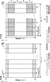
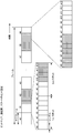
- FIG. 2 is a diagram illustrating an example of an uplink radio frame format according to the present embodiment.
- FIG. 2A illustrates a case where the base station apparatus 10 is configured to perform uplink data transmission only with non-contention based multiple access (for example, all the terminal apparatuses 20 and 30 in the cell 10a are contention-based uplinks). It is an example of a radio frame format in the case of transmission.
- FIG. 2B is an example of a radio frame format when the base station apparatus 10 is set to perform uplink data transmission on a non-contention base and a contention base.
- FIG. 2A illustrates a case where the base station apparatus 10 is configured to perform uplink data transmission only with non-contention based multiple access (for example, all the terminal apparatuses 20 and 30 in the cell 10a are contention-based uplinks). It is an example of a radio frame format in the case of transmission.
- FIG. 2B is an example of a radio frame format when the base station apparatus 10 is set to perform uplink data transmission on a non
- white areas are areas where non-contention based uplink data channels (for example, PUSCH) are transmitted (areas where terminal devices perform scheduled access) (non-contention based access areas, schedules). This is also called the “access area”.
- the shaded portion is a region where the contention-based uplink data channel is transmitted (a region where the terminal device performs contention-based access) (also referred to as a contention-based access region).
- the hatched portion with the right upward is a region where an uplink control channel (for example, PUCCH) is transmitted.
- Resources for arranging PRACH and reference signals are set to predetermined symbols (for example, reference signals are fourth and eleventh symbols) constituting a subframe.
- the frequency band (frequency resource) in which the reference signal is arranged can be allocated for each terminal device.
- the frequency band (frequency resource) in which the reference signal is allocated can be set to be the same as the frequency band to which the uplink data channel / uplink control channel is allocated.
- the frequency band in which the reference signal is allocated can be set to be the same as the frequency band to which the uplink data channel / uplink control channel is allocated.
- the frequency band in which the reference signal is allocated can be set wider than the frequency band to which the uplink data channel / uplink control channel is allocated (in FIG. 2, it is omitted for the sake of simplicity. In the same manner, reference signals and the like are omitted).
- System bandwidth consists of multiple subcarriers.
- a radio frame is composed of a plurality of subframes (in FIG. 2, one radio frame includes 10 subframes).
- One subframe is composed of a plurality of slots (in FIG. 2, one subframe includes two slots).
- the subframe includes a plurality of SC-FDMA symbols (corresponding to downlink OFDM symbols).
- a resource element is defined by one subcarrier and one SC-FDMA symbol. For example, in a certain subframe, when the number of subcarriers in the contention-based uplink data channel transmission region (shaded portion) is 300 and the number of SC-FDMA symbols is 14, that region is composed of 4200 resource elements. Is done. Similarly, also in FIGS. 3 to 7 below, each region will be described as a case where it is composed of resource elements.
- FIG. 2B shows that the uplink data channel is transmitted in an area where the uplink data channel is transmitted by contention-based multiple access (contention base access area) and in a non-contention based multiple access (non-contention base access area).
- This is an example in which the transmitted region is frequency-divided.
- the broken line is the center frequency.
- f0 and f2 are frequency bandwidths for non-contention based transmission.
- f1 and f3 are frequency bandwidths for contention-based transmission.
- the base station apparatus 10 can set the bandwidth separately for the non-contention based multiple access and the bandwidth for the contention based multiple access.
- the base station apparatus 10 may set f0 to f3 independently.
- the base station apparatus 10 can notify the terminal apparatus of the settings of the bandwidths f0 to f3 using the DCI format / RRC message / system information / broadcast channel / contention base transmission setting channel.
- the base station apparatus 10 can notify the terminal apparatus of the radio frame format setting using the DCI format / RRC message / system information / broadcast channel / contention base transmission setting channel.
- the radio frame format setting is an arrangement setting of the contention base transmission area and the non-contention base transmission area in the radio frame format.
- the base station apparatus 10 uses the DCI format / RRC message / system information / broadcast channel / contention base transmission setting channel to indicate information indicating which of the formats 2 (A) and 2 (B) is applied.
- the terminal device may be notified.
- the base station apparatus 10 may notify a period (for example, frame unit) and a system frame number (SFN) in which a radio format including a contention base transmission area is applied.
- the bandwidth setting can be included in the radio frame format setting.
- the terminal device 20 transmits an uplink data channel in a non-contention based uplink data channel transmission region (outlined portion) according to the UL grant received from the base station device 10.
- the terminal device 30 receives UL grant from the base station device 10
- the terminal device 30 transmits an uplink data channel in the non-contention based uplink data channel transmission region in accordance with the UL grant.
- the terminal device 30 does not receive the UL grant from the base station device 10 or transmits data regardless of the UL grant
- the terminal device 30 uses the uplink data channel in the contention-based uplink data transmission area (shaded portion). Send.
- the contention-based uplink data transmission region a plurality of terminal apparatuses simultaneously transmit uplink data at the same time and the same frequency.
- the contention-based uplink data transmission region is a region that allows a situation (non-orthogonal multiple access) in which the number of transmission terminal devices ⁇ the number of transmission antennas of each terminal device is equal to or greater than the number of reception antennas of the base station device.
- the terminal apparatuses 20 and 30 transmit the uplink control channel in the uplink control channel transmission region.
- the terminal apparatus 30 may transmit the uplink control channel in a contention-based uplink data channel transmission region.
- the terminal device 30 transmits the uplink control channel on a contention basis, based on the content of the UCI included in the uplink control channel (for example, whether SR, CSI, or ACK / NACK is included) It may be sent based on tension or set.
- the base station apparatus 10 transmits control information indicating in which region the uplink data channel and the uplink control channel are transmitted to the terminal apparatuses 20 and 30 in a DCI format / RRC message / system information / broadcast channel / context. Notification can be performed using a channel for setting a tension base transmission.
- the terminal devices 20-1 to 20-5 can transmit in the contention base transmission area in the odd-numbered subframe numbers, and the terminal devices 20-6 to 20-n have the even-numbered subframe numbers. It is notified that transmission is possible in the contention base transmission area.
- the terminal apparatus 20-1 to the terminal apparatus 20-5 do not depend on the UL Grant from the base station apparatus 10, but use any resource in the contention-based transmission area of the odd subframe number with the uplink data. Can be sent.
- the terminal device 20-6 to the terminal device 20-n do not depend on the UL Grant from the base station device 10, but use any resource in the contention-based transmission area of the even subframe number for the uplink data. Can be sent.
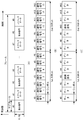
- FIG. 3 is a diagram illustrating a format example of an uplink subframe in contention-based access according to the present embodiment.
- FIG. 3 is applied to the contention-based uplink data channel region (shaded portion) in FIG.
- FIG. 3A shows a frame configuration in the contention-based transmission area.
- even-numbered subframes (# 0, # 2,..., # 8 are areas to which identification signals are assigned.
- Odd-numbered subframes (# 1, # 3,... , # 9) is an area to which an uplink data channel is allocated
- Fig. 3B is a configuration of a subframe in which an identification signal is arranged
- Fig. 3C is an arrangement of uplink data.
- each subframe is composed of 14 SC-FDMA symbols
- the identification signal is a base station. It is used for identifying a terminal device from which the device has transmitted uplink data.
- the identification signal a known sequence predetermined in the base station device and the terminal device is used.
- a known sequence predetermined in the base station device and the terminal device is used.
- FIG. 3B when a different known sequence is assigned to each SC-FDMA symbol as the identification signal, 14 terminal devices can be identified.
- the known sequence may be further subjected to predetermined phase rotation and interleaving.
- the base station apparatus can identify the terminal apparatus by a known sequence pattern, a phase rotation pattern, and an interleave pattern. Thereby, the number of terminal devices that can be identified can be increased.
- the terminal device allocates uplink data in units of subframes.
- a subframe to which uplink data is allocated includes a reference signal (for example, SC-FDMA symbols # 3 and # 10 constituting odd-numbered subframes).
- the reference signal is generated by multiplying a basic known sequence by any one of the identification signals 0 to 13.
- the base station apparatus performs propagation path estimation between the base station apparatus and the transmission terminal apparatus using the reference signal multiplied by the identification signal.
- the base station apparatus performs signal detection such as turbo equalization of the uplink data using the propagation path estimated value.
- the known sequence can also be used as a reference signal in addition to the identification signal. In this case, the base station apparatus 10 performs identification of the terminal apparatus and propagation path estimation using the known sequence.
- FIG. 4 is a diagram showing another example of the uplink radio frame format according to the present embodiment.
- white areas are areas where non-contention based uplink data channels are transmitted.
- the shaded area is an area where a contention-based uplink data channel is transmitted.
- the upward-sloping shaded area is an area where the uplink control channel is transmitted.
- FIG. 4 is an example in which a region where uplink data is transmitted on a contention basis and a region where uplink data is transmitted on a non-contention basis are time-divided.
- the non-contention based uplink data channel, the contention based uplink data channel, and the uplink control channel channel are transmitted using each region as in FIG.
- the terminal device 30 when transmitting the uplink control channel on a contention basis, the terminal device 30 can transmit the uplink control channel in the contention base uplink data channel transmission region.
- a contention-based transmission subframe can be defined in addition to a non-contention-based transmission subframe (also referred to as a normal subframe).
- subframe numbers # 1, # 3, and # 9 are subframes reserved for contention-based transmission.
- the base station apparatus 10 can transmit control information for contention-based transmission subframe setting using a DCI format / RRC message / system information / broadcast channel / contention-based transmission setting channel.
- the control information for setting the contention base transmission subframe includes a subframe number reserved for the contention base, a frequency bandwidth, and the like. Note that subframes reserved for contention base may be notified using a bitmap.
- the uplink control channel can be set to transmit only on the non-contention basis. In this case, regardless of the non-contention base transmission subframe or the contention base transmission subframe, the uplink control channel is transmitted on a non-contention basis in the uplink control channel transmission region (upward hatched portion).
- the uplink control channel can be set to transmit on the non-contention base / contention base.
- the terminal device 30 transmits the uplink control channel to the uplink control channel transmission region (subframe numbers # 1, # 3 included in the contention-based transmission subframe). , # 9 and the hatched portion rising to the right).
- an uplink control channel transmitted on a non-contention basis is transmitted in an uplink control channel transmission region included in subframes # 0, # 2, and # 4 to # 8.
- whether the transmission apparatus 30 transmits the uplink control channel on a contention basis or non-contention basis depending on the content of the UCI included in the uplink control channel. Can be set.
- the terminal apparatus 30 transmits the uplink control channel including ACK / NACK in the uplink control channel transmission region in the non-contention base transmission subframe.
- the terminal device 30 may convert the uplink control channel configured from SR into a non-contention based uplink control channel transmission region or a contention based uplink data channel transmission region, Send.
- the terminal device 30 transmits the uplink control channel including the CSI in the uplink control channel transmission region in the non-contention base transmission subframe.
- the communication system can also set whether the transmission apparatus 30 transmits the uplink control channel on a contention basis or on a non-contention basis according to the CSI attribute.
- aperiodic CSI Aperiodic CSI
- the terminal apparatus 30 transmits an uplink control channel including the aperiodic CSI in the uplink control channel transmission region in the non-contention base transmission subframe. be able to.
- periodic CSI Period CSI
- the terminal device 30 transmits an uplink control channel including the periodic CSI as an uplink control channel transmission in a non-contention based transmission subframe or a contention based transmission subframe. Can be sent in the area.
- the communication system sets whether the transmission apparatus 30 transmits a channel including the uplink control information on a contention basis or a non-contention basis according to the uplink control information format.
- You can also The setting for which transmission is performed can be associated with the content of the control information included in the uplink control information format.
- an uplink control information format composed only of SR can be transmitted in the uplink control channel transmission region in the contention-based transmission subframe.
- the base station apparatus 10 may set whether to transmit in the contention base area or in the non-contention base area according to the number of bits of the uplink control channel. For example, when the number of bits of the uplink control channel is smaller than a predetermined number, the uplink control channel is transmitted in the contention-based transmission region.
- whether to transmit the control information on a contention basis or on a non-contention basis is set according to the content of the uplink control information. Thereby, it is possible to set which transmission method is used according to the importance / priority of the uplink control information.
- the base station apparatus 10 when a region is set in units of subframes, the base station apparatus 10 sets subframe numbers # 1, # 3, and # 9 as contention-based uplink data channel transmission regions. When an area is set in slot units, the base station apparatus 10 sets slot numbers # 2, # 3, # 6, # 7, # 18, and # 19 as contention-based uplink data channel transmission areas. Note that the base station apparatus 10 transmits control information indicating in which region the uplink data channel and the uplink control channel are transmitted to the terminal apparatuses 20 and 30 in a DCI format / RRC message / system information / broadcast channel. / The contention-based transmission setting channel can be used for notification.
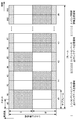
- FIG. 5 is a diagram showing another example of the uplink radio frame format according to the present embodiment.
- FIG. 5 is an example in which the contention-based uplink data transmission region and the non-contention-based uplink data transmission region are divided in frequency and time.
- FIG. 5 shows a case where non-contention base transmission areas and contention base transmission areas are alternately set in subframe units.
- the setting is performed in units of subframes, but the base station apparatus 10 can alternately set the non-contention base transmission region and the contention base transmission region in units of slots.
- the non-contention based uplink data channel, the contention based uplink data channel, and the uplink control channel channel are transmitted using each region as in FIGS.
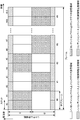
- FIG. 6 is a diagram showing another example of the uplink radio frame format according to the present embodiment.
- a white portion is an area where a non-contention based uplink data channel is transmitted.
- the shaded area is an area where a contention-based uplink data channel is transmitted.
- the hatched portion that rises to the right is a region where a non-contention based uplink control channel channel is transmitted.
- the downward slanted shaded area is an area where a contention-based uplink control channel is transmitted.
- the non-contention base uplink control channel transmission region is a region in which the terminal device transmits an uplink control channel based on the UL Grant of the base station device.
- the contention-based uplink control channel transmission region is a region in which the terminal device can transmit the uplink control channel when there is no UL Grant of the base station device or without depending on the UL Grant.
- the base station apparatus 10 can also associate the uplink control channel transmitted on a contention basis with the region in which the contention based uplink data channel is transmitted.
- the uplink control channel transmitted on a contention basis is transmitted in the uplink control channel region included in the frequency region f1 in the subframe having an even number of subframe numbers.
- the uplink control channel transmitted on a contention basis is transmitted in the uplink control channel region included in the frequency region f0 in the subframe having an odd subframe number.
- the uplink control channel transmitted on a non-contention basis is transmitted in the uplink control channel region included in the frequency region f0 in the subframe having an even number of subframe numbers.
- the uplink control channel transmitted on a non-contention basis is transmitted in the uplink control channel region included in the frequency region f1 in the subframe having an odd subframe number.
- the terminal devices 20 and 30 transmit the uplink data channel in the non-contention based uplink data channel transmission region in accordance with the UL grant received from the base station device 10.
- the terminal device 30 does not receive the UL grant received from the base station device 10 or transmits data without depending on the UL Grant, the terminal device 30 transmits an uplink data channel in the contention-based uplink data transmission region.
- the base station apparatus 10 can set whether to transmit the uplink control channel on a non-contention basis or a contention basis according to the content of the uplink control information included in the uplink control channel. For example, whether the uplink control channel is transmitted in a non-contention-based region or a contention-based region depending on which combination of ACK / NACK, CSI, and SR is included in the uplink control channel , Is determined.
- the terminal device 30 transmits the uplink control channel in the contention-based uplink control channel transmission region.
- the terminal device 30 transmits the uplink control channel in the non-contention based uplink control channel transmission region.
- the terminal device 30 transmits the uplink control channel in the non-contention base uplink control channel transmission region.
- the base station apparatus 10 may set whether the uplink control channel is transmitted in a non-contention base or a contention based area according to the UCI format.
- C-RNTI for non-contention base and C-RNTI for contention base can be defined.
- the base station apparatus 10 scrambles the downlink control channel / downlink data channel with the non-contention base C-RNTI or the contention base C-RNTI.
- the terminal device 30 can determine the region for transmitting the uplink data channel / uplink control channel based on the C-RNTI in which the downlink control channel / downlink data channel is scrambled. For example, the terminal device 30 determines an area for transmitting ACK / NACK for the downlink data channel based on the C-RNTI in which the downlink control channel / downlink data channel is scrambled.
- the terminal device 30 transmits ACK / NACK by the contention base C-RNTI.
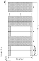
- FIG. 7 is a diagram showing another example of the uplink radio frame format according to this embodiment.
- one radio frame includes 10 subframes.
- One subframe consists of two slots.
- One slot consists of seven symbols (SC-FDMA symbol or OFDM symbol). That is, one subframe consists of 14 symbols.
- white areas are areas where non-contention based uplink data channels are transmitted.
- the shaded area is an area where a contention-based uplink data channel is transmitted.
- the base station apparatus 10 can set the contention base transmission area in symbol units. In FIG. 7, four symbols among the symbols constituting subframe # 1 are set in the contention base transmission area. In subframes # 2 and # 8, all symbols constituting the subframe are set in the contention base transmission area. Of the symbols constituting subframe # 9, seven symbols are set in the contention base transmission area.
- the base station apparatus / terminal apparatus may recognize that a part is an area that can be transmitted on a contention basis (referred to as a pre-area that can be transmitted on a contention basis).
- the base station apparatus 10 uses the DCI format / RRC message / system information / broadcast channel / contention base transmission setting channel to set the pre-region that can be transmitted in the contention base in subframes / slot units / symbol units.
- the terminal device 30 can be notified. For example, in FIG.
- the base station apparatus 10 notifies subframe number # 2 as a transmission subframe for contention base and 4 symbols as a pre-region that can be transmitted on a contention base.
- symbols # 10 to # 13 constituting subframe # 1 and all symbols constituting subframe # 2 are candidate areas for contention-based data transmission.
- the base station apparatus / terminal apparatus may recognize that a part is an area that can be transmitted on a contention basis (referred to as a post area that can be transmitted on a contention basis).
- the base station apparatus 10 uses the DCI format / RRC message / system information / broadcast channel / contention base transmission setting channel to transmit the post area in the contention base in subframe units / slot units / symbol units. Can be notified to the terminal device 30.
- FIG. 1 DCI format / RRC message / system information / broadcast channel / contention base transmission setting channel
- the base station apparatus 10 notifies subframe number # 8 as a transmission subframe for contention base and 7 symbols (slot number 1) as a pre-region that can be transmitted on contention base.
- subframe # 8 and symbols # 0 to # 6 constituting subframe # 9 are candidate areas for contention-based data transmission.
- the base station apparatus 10 notifies the terminal apparatuses 20 and 30 of control information indicating a contention base transmission area using a DCI / RRC message / system information / broadcast channel / contention base transmission setting channel. be able to.
- the base station apparatus 10 can notify control information indicating a contention base transmission area in subframe units / slot units / symbol units. For example, in FIG. 4, the base station apparatus 10 notifies the terminal apparatus of contention-based transmission subframe numbers # 1, # 3, and # 9.
- the base station apparatus 10 may notify the terminal apparatus of contention base transmission slot numbers # 2, # 3, # 6, # 7, # 18, and # 19.
- the base station apparatus 10 can also notify the terminal apparatus of the area in which contention-based transmission is performed, using a transmission interval that is continuous with the start timing for performing contention-based transmission.
- the base station apparatus 10 can notify a subframe / slot / symbol for performing contention-based transmission as a start timing.
- the base station apparatus 10 can notify the number of subframes / number of slots / number of symbols for performing contention-based transmission as an interval for continuous transmission. For example, in FIG. 4, when reporting in slot units, the base station apparatus 10 transmits slot numbers # 2, # 6, and # 18 as start slots.
- the base station apparatus 10 transmits 2 as the number of slots to be continuously transmitted. Note that the interval of continuous transmission may be notified for each start point.
- the base station apparatus 10 can also notify the terminal apparatus of the period of the region in which contention-based transmission is performed. For example, in FIG. 5, base station apparatus 10 uses “1” as the subframe period of the region in which contention-based transmission is performed, using the DCI / RRC message / system information / broadcast channel / contention-based transmission setting channel. To the terminal device. Note that the base station apparatus 10 can also notify whether an even-numbered subframe number or an odd-numbered subframe is set as a subframe in which contention-based transmission is performed.
- TDD Time Division Duplex
- the setting of the bitmap and the uplink-downlink subframe configuration (UL-DL subframe configuration, subframes constituting a radio frame)
- a contention-based uplink transmission subframe and a contention-based downlink transmission subframe can be set by a combination of settings indicating whether the frame is an uplink or a downlink.
- the uplink-downlink subframe configuration is configured by a combination of a non-contention based uplink subframe, a non-contention based downlink subframe, a contention-based transmission transmission subframe, and a special subframe.
- the uplink-downlink subframe configuration is set to a non-contention based uplink subframe, a non-contention based downlink subframe, a contention based uplink subframe, a contention based downlink subframe, and a special subframe. Consists of.
- the special subframe is a subframe arranged between the downlink subframe and the uplink subframe, and includes a DwPTS field, a GP field, and an UpPTS field.
- the communication system according to the present embodiment can set a special subframe as a subframe that prohibits contention-based transmission.
- the base station device 10 can notify the terminal device whether it supports contention-based transmission.
- the base station device 10 that supports contention-based transmission can also notify the terminal device of the setup and release of contention-based transmission.
- the base station apparatus 10 may notify the presence / absence of contention-based transmission support / contention-based transmission setup / release by transmitting the bitmap indicating the contention-based transmission subframe.
- the base station apparatus 10 uses the DCI format / RRC message / system information / broadcast channel / contention base transmission setting channel for the presence / absence of contention based transmission support / contention base transmission setup / release. Can be notified.
- the terminal device can receive a function supported by the base station device 10 and select a cell to be connected. For example, a terminal device that desires contention-based transmission can make a connection request to a base station device with the highest received power among base station devices that support contention-based transmission.
- the base station apparatus 10 can apply a carrier aggregation (Carrier Aggregation: CA) that performs broadband transmission by combining a plurality of component carriers (CC: Ca Component Carrier).
- CA Carrier Aggregation
- the base station apparatus can independently set the frame format in the primary cell (Primary Cell: PCell) and / or the secondary cell (Secondary Cell: SCell).
- the base station apparatus can transmit an uplink data channel on a contention basis in Pcell, and can transmit an uplink data channel on a non-contention basis in Scell.
- the base station apparatus 10 may be set not to apply carrier aggregation.
- the base station apparatus 10 can also be set not to allocate uplink data to Scell subframes transmitted at the same timing as subframes in which uplink data signals are transmitted on a contention basis in the Pcell.
- the base station apparatus 10 may set the number of component carriers that can be contention-based transmitted according to the number of terminal apparatuses that perform contention-based transmission. Note that these settings may be interchanged between Pcell and Scell.
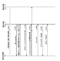
- FIG. 8 is a diagram showing a sequence example of uplink transmission in non-contention based access according to the present embodiment.
- Base station apparatus 10 periodically transmits a synchronization signal, a broadcast channel, and the like in a downlink using a predetermined subframe.
- the terminal device 30-1 performs initial connection (including handover) using a synchronization signal, a broadcast channel, and the like (S101).
- the terminal device performs frame synchronization and symbol synchronization using the synchronization signal.
- the terminal device specifies the cell ID, system bandwidth, SFN, and the like by the broadcast channel.
- the broadcast channel may include setting information for contention based transmission. In this case, the terminal device specifies the setting related to contention-based transmission in the connected cell.
- the setting information for contention-based transmission includes information indicating that contention-based transmission is supported, information about a radio frame format, control information for contention-based transmission, information about terminal device identification (related to an identification signal) Information) and the like. Note that the base station apparatus 10 also performs initial connection to the terminal apparatuses 20 and 30.
- the terminal device 30-1 transmits UE Capability (S102).
- the base station apparatus can specify whether or not the terminal apparatus supports contention-based transmission using the UE capability. For example, the UE Capability is transmitted using an RRC message or the like.
- the base station apparatus transmits setting information related to radio resource control to the terminal apparatus (S103).
- the configuration information related to radio resource control can include a part or all of the configuration information for contention-based transmission. Note that the terminal devices 20 and 30 and the base station device 10 also perform the processes of S102 and S103.
- the setting information related to the radio resource control can include setting information for contention-based transmission in addition to setting information for non-contention-based transmission.
- the setting information for radio resource control is transmitted using an RRC message or the like.
- the terminal device transmits a scheduling request (SR) and a buffer status report (BSR) to transmit uplink data on a non-contention basis (S104).
- the base station apparatus allocates radio resources for uplink data transmission to each terminal apparatus in consideration of the BSR and the like.
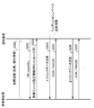
- the base station apparatus sets the format FIG. 2B including the contention base transmission area as the uplink radio frame format.
- the base station apparatus sets the format FIG. 2B including the contention base transmission area as the uplink radio frame format.
- the base station apparatus sets the format FIG. 2B including the contention base transmission area as the uplink radio frame format.
- the base station apparatus sets the format FIG. 2B including the contention base transmission area as the uplink radio frame format.
- the base station apparatus sets the format FIG. 2B including the contention base transmission area as the uplink radio frame format.
- the base station apparatus sets the format FIG. 2B including the contention base transmission area as the uplink radio frame format.
- the base station apparatus sets the format FIG. 2B including the contention base transmission area as the uplink radio frame format.
- the base station apparatus sets the format FIG. 2B including the contention base transmission area as the uplink radio frame format.
- the base station apparatus sets the format FIG. 2B including the contention base transmission area as the uplink radio frame format.
- the base station apparatus sets the format FIG. 2B
- the contention-based transmission setting change may be information for releasing a contention-based transmission by a subframe including the radio resource allocation.
- the contention-based transmission setting change may be a changed bandwidth (f0 to f3 after the change) in a subframe including the radio resource assignment.
- a DCI / RRC message / system information / contention-based transmission setting channel or the like can be used.
- the base station device transmits an uplink transmission permission (UL Grant) to the terminal device using DCI (S106).
- the terminal device transmits uplink data using a predetermined radio resource based on the uplink transmission parameters included in the UL Grant (S107).
- the base station apparatus transmits ACK / NACK for the uplink data (S107).
- the base station apparatus can control the contention base transmission area. For example, uplink data transmission is performed in 4 ms after receiving UL Grant (when one subframe period is 1 ms, uplink data is transmitted four subframes after the subframe in which UL Grant is received).
- the uplink data transmission allocated by this UL Grant is a non-contention based transmission subframe (for example, when UL Grant is transmitted 4 subframes before subframe # 1 in FIG. 4)
- the base station The device transmits the contention-based transmission setting change.
- FIG. 9 is a diagram illustrating a sequence example of uplink transmission in contention-based access according to the present embodiment.
- Base station apparatus 10 periodically transmits a synchronization signal, a broadcast channel, and the like in a downlink using a predetermined subframe.
- the terminal device performs initial connection using a synchronization signal, a broadcast channel, etc. (S201).
- the terminal device performs frame synchronization and symbol synchronization using the synchronization signal.
- the terminal device specifies the cell ID, system bandwidth, SFN, and the like by the broadcast channel.
- the setting information for contention-based transmission is included in the broadcast channel, the terminal device specifies settings related to contention-based transmission in the connected cell.
- the terminal device transmits UE Capability (S202).
- the base station apparatus can specify whether the terminal apparatus supports contention-based transmission using the UE capability. For example, the UE Capability is transmitted using an RRC message or the like.
- the base station apparatus transmits setting information related to radio resource control to the terminal apparatus (S203).
- the setting information related to the radio resource control can include control information for contention-based transmission.
- the setting information for radio resource control is transmitted using an RRC message or the like.
- Each terminal device uses the setting information for contention-based transmission and the setting information for radio resource control to transmit a contention-based area, a period for contention-based transmission, a contention-based transmission An identification signal assigned for transmission is specified.
- a terminal device supporting the contention base transmits the uplink data using an identification signal given to the wireless base station using an arbitrary radio resource in the contention base transmission area.
- the base station apparatus transmits ACK / NACK for the uplink data (S205).
- the terminal device supporting the contention base may transmit the uplink control information using an arbitrary radio resource in the contention base transmission region.
- the radio resource for transmitting the uplink control information may be determined according to the content thereof.
- ACK / NACK is transmitted in 4 ms after receiving downlink data (when one subframe period is 1 ms, ACK / NACK is transmitted four subframes after the subframe in which downlink data is received).
- uplink control information including ACK / NACK is transmitted in subframe # 0.
- the uplink control information including ACK / NACK is transmitted on a contention basis in the uplink control information transmission region (upwardly hatched portion) of subframe # 0.
- the uplink control information can be transmitted on a contention basis in a contention base transmission region (shaded portion). .
- the base station apparatus transmits the uplink data within the contention-based transmission area regardless of UL Grant (S206, S207).
- the terminal apparatus transmits uplink data based on the period.
- FIG. 10 is a schematic block diagram showing the configuration of the base station apparatus 10 in the present embodiment.
- the base station apparatus 10 includes an upper layer processing unit (upper layer processing step) 101, a control unit (control step) 102, a transmission unit (transmission step) 103, a reception unit (reception step) 104, a transmission antenna 105, and a reception antenna 106. Consists of including.
- the transmission unit 103 generates a transmission signal (downlink channel) to the terminal devices 20 and 30 according to the logical channel input from the higher layer processing unit 101.
- the transmission unit 103 includes an encoding unit (encoding step) 1031, a modulation unit (modulation step) 1032, a downlink reference signal generation unit (downlink reference signal generation step) 1033, a multiplexing unit (multiplexing step) 1034, and radio transmission Unit (wireless transmission step) 1035.
- the reception unit 104 includes a radio reception unit (radio reception step) 1041, a demultiplexing unit (demultiplexing step) 1042, a signal detection unit (signal detection step) 1043, a propagation path estimation unit (propagation path estimation step) 1044, and an identification unit ( (Identification step) 1045.
- the upper layer processing unit 101 includes a medium access control (Medium Access Control: MAC) layer, a packet data integration protocol (Packet Data Convergence Protocol: PDCP) layer, a radio link control (Radio Link Control: RLC) layer, a radio resource control (Radio) Processes higher layers than physical layer such as Resource (Control: RRC) layer.
- Upper layer processing section 101 generates information necessary for controlling transmission section 103 and reception section 104 and outputs the information to control section 102.
- Upper layer processing section 101 outputs uplink data (for example, DL-SCH) and broadcast information (for example, BCH) to transmission section 103.
- uplink data for example, DL-SCH
- broadcast information for example, BCH
- the upper layer processing unit 101 receives information related to the terminal device such as the function (UE capability) of the terminal device from the terminal devices 20 and 30 (via the receiving unit 104). In other words, the terminal apparatus transmits its own function to the base station apparatus using an upper layer signal.
- the information regarding the terminal device includes information indicating whether or not the terminal device supports a predetermined function, or information indicating that the terminal device is introduced into the predetermined function and the test is completed. Whether or not to support a predetermined function includes whether or not the installation and test for the predetermined function have been completed.
- the terminal device when a terminal device supports a predetermined function, the terminal device transmits information (parameters) indicating whether the predetermined function is supported. When a terminal device does not support a predetermined function, the terminal device may not transmit information (parameter) indicating whether or not the predetermined device is supported. That is, whether or not to support the predetermined function is notified by whether or not information (parameter) indicating whether or not to support the predetermined function is transmitted. Note that information (parameter) indicating whether or not to support a predetermined function may be notified using 1 bit of 1 or 0.
- the information on the terminal device includes information indicating that contention-based transmission is supported and information indicating that carrier aggregation is supported (information indicating the number of component carriers that can be aggregated may be included).
- the terminal device can transmit information indicating whether to support each function.
- Functions that support contention-based transmission include the ability to support multiple tables indicating antenna ports, scrambling identities, and the number of layers, the ability to support a predetermined number of antenna ports, and the number of component carriers for carrier aggregation. Or a part or all of the ability corresponding to the number of resource blocks and the ability corresponding to a predetermined transmission mode.
- the transmission mode is determined by the number of antenna ports, transmission diversity, the number of layers, and the like.
- the ability to support a predetermined transmission mode can include, for example, being able to support contention-based transmission in the FDD format and being able to support contention-based transmission in the TDD format.
- the terminal device can transmit information indicating which FDD / TDD format is supported as information on the terminal device.
- the upper layer processing unit 101 generates or acquires downlink data (transport block), system information, RRC message, MAC CE, and the like arranged on the downlink PDSCH from the upper node. Upper layer processing section 101 outputs downlink data to transmitting section 103.
- the upper layer processing unit 101 manages various setting information of the terminal devices 20 and 30.
- the upper layer processing unit 101 determines contention-based transmission area allocation that allows each terminal device to transmit to a terminal device that supports contention-based transmission, and allocation of an identification signal to each terminal device. To do.
- Information related to contention-based transmission area allocation and identification signal allocation to each terminal device can be included in various setting information. Part of the radio resource control function may be performed in the MAC layer or the physical layer.
- the upper layer processing unit 101 sets a cell radio network temporary identifier (C-RNTI: “Cell Radio Network Temporary Identifier”) for each terminal device.
- the cell radio network temporary identifier includes a contention base specific identifier.
- C-RNTI is used for encryption (scrambling) of a downlink control channel and a downlink data channel in non-contention based transmission.
- C-RNTI can be used for encryption (scrambling) of identification signals, uplink data channels, and uplink control channels in contention-based transmission.
- the contention-based unique identifier can be used to identify the terminal device.
- the various setting information includes setting information related to contention base transmission.
- Information related to contention-based transmission can include information related to the contention-based transmission area allocation and the allocation of identification signals to each terminal device.
- the setting information related to contention-based transmission can include parameters indicating contention-based transmission area setting, contention-based unique identifier setting, contention-based setup, and release.
- the information related to contention-based transmission may include a parameter indicating a period (transmission interval) in contention-based transmission.
- Information regarding contention-based transmission may include information indicating a contention-based transmission subframe.
- the information related to contention-based transmission may include information indicating contention-based transmission setting change (contention-based transmission prohibition notification).
- the upper layer processing unit 101 receives various setting information such as information indicating that the base station apparatus 10 supports contention-based transmission and setting information related to contention-based transmission (also referred to as contention-based transmission setting assist information). Then, the data is transmitted to the terminal device via the transmission unit 103.
- Configuration information related to contention-based transmission can be included in individual radio resource configuration parameters (for example, RadioResourceConfigDedicated in LTE-A).
- Information regarding contention based transmission may also be included in cell specific radio resource configuration parameters.
- Information regarding contention-based transmission may be defined as radio resource parameters specific to contention-based transmission.
- upper layer processing section 101 In non-contention based transmission, upper layer processing section 101 considers contention based transmission subframes, and assigns frequency and time resources (subcarriers and subframes) to allocate physical channels (PDSCH and PUSCH) to be transmitted to each terminal apparatus. ). Upper layer processing section 101 determines the coding rate and modulation scheme (or MCS), transmission power, etc. of physical channels (PDSCH and PUSCH). The upper layer processing unit 101 generates information used for scheduling of non-contention based physical channels (PDSCH and PUSCH) based on the scheduling result. The upper layer processing unit 101 outputs the generated information to the control unit 102. The upper layer processing unit 101 outputs a part or all of the setting information regarding the contention base transmission to the control unit 102.
- MCS modulation scheme
- the control unit 102 generates a control signal for controlling the transmission unit 103 and the reception unit 104 based on various setting information input from the higher layer processing unit 101.
- the control unit 102 generates downlink control information (DCI) based on the information input from the higher layer processing unit 101 and outputs the downlink control information (DCI) to the transmission unit 103.
- the downlink control information includes a PDSCH / PUSCH resource allocation field, a HARQ process number field, and a new data indicator (NDI: “New” Date “Indicator) field.
- the control unit 102 can include a part of setting information for contention-based transmission in the downlink control signal.
- CRC Cyclic Redundancy Check
- the CRC is generated for the generated DCI format data series.
- the CRC is encrypted (scrambled) by C-RNTI (Cell-Radio Network Temporary Identifier).
- the C-RNTI may use a contention base unique identifier.
- the contention-based unique identifier may be used to indicate to the terminal device that uplink data / uplink control data can be transmitted in the contention base region.
- the encrypted CRC is added to the DCI format.
- the signal generated as the DCI format is arranged on the PDCCH.
- the transmission unit 103 generates a downlink reference signal according to the control signal input from the control unit 102.
- Transmitter 103 encodes and modulates broadcast information, downlink control information, and downlink data input from higher layer processing section 101 for each terminal apparatus, and generates PHICH, PDCCH, EPDCCH, PDSCH, and PBCH. To do.
- Transmitter 103 multiplexes PHICH, PDCCH, EPDCCH, PDSCH, PBCH, and a downlink reference signal, and transmits the multiplexed signal to the terminal device via transmission antenna 105.
- the encoding unit 1031 performs block coding on downlink control information and downlink data input from the higher layer processing unit 101 using a predetermined encoding method determined by the upper layer processing unit 101, Encoding such as convolutional coding and turbo coding is performed.
- the modulation unit 1032 converts the coded bits input from the coding unit 1031 into predetermined BPSK (Binary Phase Shift Keying), QPSK (quadrature Phase Shift Keying), 16 QAM (quadrature Amplitude Modulation), 64 QAM, 256 QAM, etc. Modulation is performed by the modulation method determined by the upper layer processing unit 101.
- the downlink reference signal generation unit 1033 generates a sequence known by the terminal device as a downlink reference signal.
- the known sequence is determined by a predetermined rule based on a physical cell identifier (PCI, cell ID) for identifying the base station apparatus 10 or the like.
- PCI physical cell identifier
- the multiplexing unit 1034 multiplexes the modulated modulation symbol of each channel, the generated downlink reference signal, and downlink control information. That is, multiplexing section 1034 arranges the modulated modulation symbol of each channel, the generated downlink reference signal, and downlink control information in the resource element.
- the radio transmission unit 1035 generates an OFDM symbol by performing inverse fast Fourier transform (Inverse Fourier Transform: IFFT) on the multiplexed modulation symbols and the like.
- the radio transmission unit 1035 generates a baseband digital signal by adding a cyclic prefix (CP) to the OFDM symbol.
- the wireless transmission unit 1035 converts the digital signal into an analog signal, removes excess frequency components by filtering, up-converts the carrier signal to a carrier frequency, amplifies the power, and outputs to the transmission antenna 105 for transmission.
- the receiving unit 104 detects (separates, demodulates, decodes) the received signals received from the terminal devices 20 and 30 via the receiving antenna 106 in accordance with the control signal input from the control unit 102, and processes the decoded information in higher layer processing. Output to the unit 101.
- the radio reception unit 1041 converts an uplink signal received via the reception antenna 106 into a baseband signal by down-conversion, removes unnecessary frequency components, and amplifies the signal level so that the signal level is properly maintained. The level is controlled, quadrature demodulation is performed based on the in-phase component and the quadrature component of the received signal, and the analog signal that has been demodulated is converted into a digital signal. Radio receiving section 1041 removes a portion corresponding to CP from the converted digital signal. The radio reception unit 1041 performs fast Fourier transform (FFT) on the signal from which the CP has been removed, and extracts a frequency domain signal. The frequency domain signal is output to the demultiplexing unit 1042. Further, radio reception section 1041 outputs a signal from which CP has been removed to identification section 1045 in the contention base transmission area.
- FFT fast Fourier transform
- the identification unit 1045 extracts the identification signal in the contention base transmission area.
- the identification unit 1045 identifies the terminal apparatus that has transmitted the uplink data on a contention basis using the identification signal.
- the identification unit 1045 outputs the information of the transmission terminal device to the propagation path estimation unit 1044 and the demultiplexing unit 1042.
- the transmission terminal apparatus is identified by blind detection using correlation processing between the identification signal held by the base station apparatus 10 and the extracted identification signal.
- the demultiplexing unit 1042 separates the signal input from the radio receiving unit 1041 into signals such as an uplink data channel and an uplink control channel based on the uplink radio frame format. In the contention-based transmission region, the demultiplexing unit 1042 separates the frequency domain signal into an uplink data channel, an uplink control channel, and a reference signal using information on the transmission terminal device identified by the identification unit 1045. The separated reference signal is input to the propagation path estimation unit 1044. The separated uplink data channel and uplink control channel are output to the signal detector 1043.
- the demultiplexing unit 1042 allocates radio resources included in the uplink grant that the base station device 10 has determined in advance by the higher layer processing unit 101 and notified to each of the terminal devices 20 and 30. Based on the information, signal separation is performed.
- the propagation path estimation unit 1044 receives information of a transmission terminal device identified as a reference signal (for example, DMRS) that is time-multiplexed with a data signal.
- the propagation path estimation unit 1044 estimates the frequency response using the reference signal, and outputs the frequency response estimated for demodulation to the signal detection unit 1043.
- the propagation path estimation part 1044 estimates the frequency response used by the uplink scheduling in a contention base, when SRS (Sounding * Reference * Signal) is input.
- FIG. 11 is a diagram illustrating an example of a signal detection unit according to the present embodiment.
- the signal detection unit 1043 includes a cancellation unit 1501, an equalization unit 1502, IDFT units 1503-1 to 1503-u, demodulation units 1504-1 to 1504-u, decoding units 1505-1 to 1505-u, and replica generation unit 1506. Composed.
- u is the number of terminal apparatuses that are non-orthogonal / orthogonal multiplexed at the same time and at the same frequency.
- the signal for each terminal device extracted from the demultiplexing unit 1042 is input to the cancellation unit 1501.
- the cancel unit 1501 performs a cancel process on each received signal using the soft replica input from the replica generation unit 1506.
- the equalization unit 1502 generates equalization weights based on the MMSE standard from the frequency response input from the propagation path estimation unit 1044.
- the equalization unit 1502 multiplies the signal after soft cancellation (input signal from the cancellation unit 1501) by the equalization weight.
- the equalization unit 1502 outputs the signal for each terminal device after equalization to the IDFT units 1503-1 to 1503-u.
- IDFT sections 1503-1 to 1503-u convert the received signal after frequency domain equalization into a time domain signal.
- the demodulation units 1504-1 to 1504-u receive information on modulation schemes that have been notified in advance or that have been determined in advance.
- Demodulating sections 1504-1 to 1504-u perform demodulation processing on the time domain signal based on the modulation scheme information, and output a bit sequence LLR (Log Likelihood Ratio).
- decoding unit 1505-1 to 1505-u receives information of a coding rate that has been notified in advance or determined in advance.
- Decoding sections 1505-1 to 1505-u perform decoding processing on the LLR sequence output from the demodulation section.
- decoding units 1505-1 to 1505-u output an external LLR or a posteriori LLR as a decoding unit output to replica generation unit 1506 To do.
- the difference between the external LLR and the posterior LLR is whether or not the prior LLR input to the decoding units 1505-1 to 1505-u is subtracted from the decoded LLR.
- the signal detection unit 1043 sends the decoding units 1505-1 to 1505-u to Depuncturing (inserting 0 into the LLR of the thinned bits), deinterleaving (returning the rearrangement), and descrambling are performed on the input LLR sequence.
- the replica generation unit 1506 generates a symbol replica from the LLR sequence input from each decoding unit according to the modulation scheme applied to data transmission by each terminal apparatus. Further, the replica generation unit 1506 converts the symbol replica into a frequency domain signal by DFT, assigns a signal to a resource used by each terminal apparatus, and multiplies the frequency response input from the propagation path estimation unit 1044. Create a soft replica. When the number of SIC or turbo equalization iterations reaches a predetermined number, decoding sections 1505-1 to 1505-u make a hard decision on the decoded LLR sequence and input it to upper layer processing section 101.
- the upper layer processing unit 101 determines the presence / absence of an error bit based on a cyclic redundancy check (CRC: Cyclic Redundancy Check).
- CRC Cyclic Redundancy Check
- the transmitting unit 103 transmits information on the presence / absence of the error bit (ACK / NACK in uplink transmission) using PHICH / PDCCH / EPDCCH.
- signal detection using turbo equalization processing has been described, but maximum likelihood detection, EMMSE-IRC, or the like can also be used.
- FIG. 12 is a schematic block diagram showing the configuration of the terminal devices 20 and 30 in the present embodiment.
- the terminal devices 20 and 30 include an upper layer processing unit (upper layer processing step) 201, a control unit (control step) 202, a transmission unit (transmission step) 203, a reception unit (reception step) 204, a transmission antenna 205, and a reception antenna 206. It is comprised including.
- the transmission unit 203 includes an encoding unit (encoding step) 2031, a modulation unit (modulation step) 2032, an uplink reference signal generation unit (uplink reference signal generation step) 2033, a multiplexing unit (multiplexing step) 2034, and a radio transmission unit (Wireless transmission step) 2035 is included.
- the reception unit 204 includes a wireless reception unit (wireless reception step) 2041, a demultiplexing unit (demultiplexing step) 2042, a demodulation unit (demodulation step) 2043, and a decoding unit (decoding step) 2044.
- the upper layer processing unit 201 includes a medium access control (Medium Access Control: MAC) layer, a packet data integration protocol (Packet Data Convergence Protocol: PDCP) layer, a radio link control (Radio Link Control: RLC) layer, a radio resource control (Radio) Resource (Control: RRC) layer processing.
- Upper layer processing section 201 outputs information (UE Capability) indicating the function of the terminal apparatus supported by the terminal apparatus to transmitting section 203.
- the information indicating the function of the terminal device supported by the terminal device includes information indicating that contention-based transmission is supported, information indicating that carrier aggregation is supported, and the like.
- the upper layer processing unit 201 can transmit information indicating whether to support each function. For example, the upper layer processing unit 201 signals information indicating the function of the terminal device supported by the terminal device on the RRC layer.
- the upper layer processing unit 201 manages various setting information of the own terminal device. A part of the various setting information is input to the control unit 202. Part of the various setting information is received from the base station apparatus 10 via the receiving unit 204.
- the various setting information includes information indicating an uplink radio frame format.
- the various setting information includes setting information related to contention-based transmission received from the base station apparatus 10.
- Information on contention-based transmission includes the contention-based transmission area allocation, information on allocation of identification signals to each terminal device, contention-based unique identifier setting, contention-based setup, release parameters, contention A parameter indicating a period (transmission interval) in base transmission, information indicating contention base transmission subframes, information indicating contention base transmission setting change, and the like are included.
- the upper layer processing unit 201 manages radio resources for transmitting uplink data (transport blocks) on a contention basis based on information on contention-based transmission.
- the upper layer processing unit 201 outputs uplink data generated by a user operation or the like to the transmission unit 203.
- the higher layer processing unit 201 can also output uplink data generated without user operation (for example, data acquired by a sensor) to the transmission unit 203.
- Upper layer processing section 201 acquires setting information related to CSI feedback transmitted from the base station apparatus, and outputs the setting information to control section 202.
- Upper layer processing section 201 outputs ACK / NACK and SR for downlink data to control section 202.
- the upper layer processing unit 101 interprets downlink control information (DCI) received via the receiving unit 204 and determines scheduling information.
- the upper layer processing unit 101 can interpret information related to contention-based transmission included in the downlink control information.
- Upper layer processing section 101 generates control information for controlling receiving section 204 and transmitting section 203 based on the scheduling information, and outputs the control information to control section 202.
- the control unit 202 generates uplink control information (UCI) based on the information input from the higher layer processing unit 201 and outputs it to the transmission unit 203.
- the control unit 202 can perform control so that UCI is transmitted on a contention basis based on information on contention-based transmission.
- the control unit 202 can generate a CRC (Cyclic Redundancy Check) for the data sequence in the UCI format.
- the CRC may be encrypted (scrambling) by C-RNTI (Cell-Radio Network Temporary Identifier).
- the C-RNTI may use a contention base unique identifier.
- the control unit 202 can also encrypt the CRC using an identification signal.
- the encrypted CRC is added to the UCI format.
- the signal generated as the UCI format is arranged in the uplink control channel transmission area / contention base transmission area.
- the receiving unit 204 separates, demodulates, and decodes the received signal received from the base station apparatus 10 via the receiving antenna 206, and outputs the decoded information to the upper layer processing unit 201.
- the radio reception unit 2041 converts a downlink signal received via the reception antenna 206 into a baseband signal by down-conversion, removes unnecessary frequency components, and amplifies the signal level so that the signal level is appropriately maintained. , And quadrature demodulation based on the in-phase and quadrature components of the received signal, and converting the quadrature demodulated analog signal into a digital signal.
- Radio receiving section 2041 removes a portion corresponding to CP from the converted digital signal, performs fast Fourier transform on the signal from which CP is removed, and extracts a frequency domain signal.
- the demultiplexing unit 2042 demultiplexes the extracted frequency domain signals into downlink channels (PHICH, PDCCH, EPDCCH, PDSCH) and downlink reference signals, respectively.
- the demultiplexing unit 2042 performs channel compensation of PHICH, PDCCH, PDSCH, and EPDCCH based on channel estimation values obtained from channel measurement using downlink reference signals.
- the demultiplexing unit outputs each downlink channel to the demodulation unit 2043.
- the demodulation unit 2043 demodulates the received signal for each modulation symbol of each downlink channel using a predetermined modulation method such as BPSK, QPSK, 16QAM, 64QAM, and 256QAM, or notified in advance by a downlink grant. To do.
- the decoding unit 2044 decodes the demodulated coded bits of each downlink channel at a coding rate that is determined in advance according to a predetermined encoding method or notified in advance by a downlink grant.
- the uplink data and the uplink control information are output to the higher layer processing unit 201.
- the decoding unit 2044 performs decoding using the encoded bits held in the HARQ buffer input from the higher layer processing unit 201 and the demodulated encoded bits.
- the transmission unit 203 generates an uplink reference signal according to the control signal input from the control unit 202.
- the transmission unit 203 encodes and modulates the uplink data (transport block) and the uplink control signal input from the higher layer processing unit 201 to generate PUCCH and PUSCH.
- PUSCH / PUCCH transmitted in contention base is encrypted (scrambled) using an identification signal.
- the PUSCH / PUCCH transmitted in contention base may be encrypted (scrambled) using C-RNTI.
- the transmission unit 203 multiplexes the PUCCH, PUSCH, and the generated uplink reference signal, and transmits the multiplexed uplink reference signal to the base station apparatus 10 via the transmission antenna 205.
- the encoding unit 2031 performs encoding such as convolutional encoding and block encoding on the uplink control information input from the higher layer processing unit 201.
- the encoding unit 2031 performs encoding such as turbo encoding on the uplink data channel.
- the modulation unit 2032 modulates the coded bits input from the coding unit 2031 using a modulation scheme notified by downlink control information such as BPSK, QPSK, 16QAM, 64QAM, or a modulation scheme predetermined for each channel. .
- the uplink reference signal generation unit 2033 identifies a physical cell identifier (physical cell identity: PCI, Cell ID, etc.) for identifying the base station apparatus 10, a bandwidth for arranging an uplink reference signal, and an uplink grant A sequence determined by a predetermined rule (formula) is generated on the basis of the cyclic shift and the parameter value for generating the DMRS sequence notified in (1).
- the uplink reference signal may be multiplied by an identification signal.
- the identification signal generation unit 2036 generates a sequence determined by a predetermined rule (formula) based on setting information regarding contention-based transmission.
- the sequence for the identification signal may be an orthogonal sequence such as an M sequence, a Zadoff Chu sequence, a Hadamard sequence, or a quasi-orthogonal sequence (pseudo-orthogonal sequence).
- the multiplexing unit 2034 rearranges the modulation symbols of the uplink data channel in parallel based on the allocation of radio resources included in the downlink control information (UL Grant), and then performs discrete Fourier transform ((DFT). .
- the multiplexing unit 2034 multiplexes the uplink control channel signal, the uplink data channel signal, and the uplink reference signal for each transmission antenna port. That is, the multiplexing unit 2034 arranges the uplink control channel signal, the uplink data channel signal, and the uplink reference signal in the resource element for each transmission antenna port.
- the multiplexing unit 2034 arranges the uplink data channel / uplink control channel / identification signal for contention-based transmission in the resource element of the contention-based transmittable area assigned to the terminal device.
- the multiplexing unit 2034 is arranged in the resource element of the same frequency band as the identification signal and the uplink data channel for contention-based transmission. Thereby, the identification signal can be used for identification of the transmission terminal apparatus and propagation path estimation.
- the radio transmission unit 2035 performs inverse fast Fourier transform (Inverse Fourier Transform: IFFT) on the multiplexed signal, performs SC-FDMA modulation, and generates an SC-FDMA symbol.
- IFFT inverse fast Fourier transform
- the wireless transmission unit 2035 adds a CP to the SC-FDMA symbol to generate a baseband digital signal. Further, the radio transmission unit 2035 converts the baseband digital signal into an analog signal, removes an extra frequency component, converts it into a carrier frequency by up-conversion, amplifies the power, and transmits a base station via the transmission antenna 205. Transmit to device 10.
- the communication system can flexibly control the contention base transmission area and the non-contention base transmission area.
- the communication system transmits an uplink data channel and an uplink control channel on a contention basis / non-contention basis according to the contents thereof. For this reason, it is possible to maintain the uplink data transmitted by each terminal device at a predetermined communication quality even in a cell in which terminal devices that perform contention-based transmission and terminal devices that perform non-contention-based transmission coexist.
- the communication system according to this embodiment includes the base station apparatus 10 and the terminal apparatuses 20 and 30 described with reference to FIGS. 1 and 10 to 12.
- differences / additional points from the first embodiment will be mainly described.
- FIG. 13 is a diagram illustrating an example of an uplink radio frame format according to the present embodiment.
- white portions are regions (resources) in which a non-contention based uplink data channel (for example, PUSCH) is transmitted.
- the shaded area is an area where a contention-based uplink data channel is transmitted.
- the hatched portion with the right upward is a region where an uplink control channel (for example, PUCCH) is transmitted.
- PUCCH uplink control channel
- the subframe format shown in FIG. 3 can be applied to the contention-based uplink data transmission area (shaded part).
- Resources for allocating PRACH and reference signals are set to predetermined symbols constituting a subframe.
- the reference signals are arranged over the system bands of the fourth and eleventh subframes (in FIG. 13, they are omitted for the sake of simplification. Etc. are omitted).
- the radio frame in FIG. 13 includes resource elements as in the radio frame shown in the first embodiment.
- FIG. 13 is an example in which an area where uplink data is transmitted on a contention basis and an area where uplink data is transmitted on a non-contention basis are time-divided.
- Subframes # 1, # 3, and # 9 are subframes reserved for contention-based transmission.
- the radio frame format according to the present embodiment does not include the uplink control channel transmission region (upward diagonally shaded portion) in the contention-based transmission subframe.
- the base station apparatus 10 has a radio frame format that allows only contention-based transmission (FIG. 2A), a radio frame format that includes an uplink control channel transmission area in the contention-based transmission subframe (FIG. 2B), 4 to 7), the radio frame format (FIG. 13) including the uplink control channel transmission region can be switched only in the non-contention base transmission subframe.
- the base station apparatus 10 can transmit control information for contention-based transmission subframe setting using a DCI format / RRC message / system information / broadcast channel / contention-based transmission setting channel.
- the base station apparatus 10 can apply the uplink sequence of FIG. 8 in the non-contention base transmission region.
- the terminal device 30 transmits uplink data using the radio resource (resource element) allocated after a predetermined time. For example, the terminal device 30 transmits uplink data after four subframes from the timing at which UL Grant is received.
- the base station apparatus sets the format FIG. 13 including the contention base transmission area as the uplink radio frame format.
- the base station apparatus 10 receives UL Grant at a timing four subframes before subframe # 9 (contention base transmission area) in the downlink, the base station apparatus 10 notifies the contention base transmission setting change ( S105).
- the contention-based transmission setting change includes information indicating that the subframe including the radio resource allocation is prohibited from contention-based transmission.
- a DCI / RRC message / system information / contention-based transmission setting channel or the like can be used.
- the base station apparatus 10 can replace the contention-based transmission setting change by notifying the release of the contention-based transmission subframe.
- the base station device 10 When transmitting the UL Grant in the contention-based transmission subframe, the base station device 10 transmits information indicating that the subframe is contention-based transmission prohibited to the terminal device.
- the base station apparatus 10 can broadcast the contention-based transmission prohibition to terminal apparatuses connected to the cell.
- the base station apparatus 10 may transmit the contention-based transmission prohibition to a terminal apparatus that is permitted to transmit in the target contention-based transmission area.
- FIG. 14 is a diagram showing a sequence example of uplink control channel transmission according to the present embodiment.
- the uplink control channel has a plurality of uplink control information (UCI) formats.
- UCI including ACK / NACK occurs after a predetermined time (for example, 4 subframes after receiving the downlink data channel) after receiving the downlink data channel. For example, when the terminal apparatus 30 receives a downlink data channel at a timing four subframes before subframe # 9 in the downlink, the transmission timing of ACK / NACK is subframe # 9.
- UCI including SR and CSI is periodically generated.
- the terminal device determines whether the UCI includes ACK / NACK. When ACK / NACK is not included in UCI (YES in S302), the terminal device transmits PUCCH including the UCI in the contention-based transmission subframe (S303). On the other hand, if the UCI includes ACK / NACK (NO in S302), the terminal device transmits the PUCCH including the UCI in the next non-contention base transmission subframe (for example, subframe # 0 in FIG. 13) ( S304).
- a subframe for transmitting the uplink control channel when transmission of an uplink control channel occurs in a contention-based transmission subframe, a subframe for transmitting the uplink control channel can be defined in advance. For example, when uplink control channel transmission occurs in a contention-based transmission subframe, it is defined to transmit in a non-contention-based transmission subframe after N subframes (N is a natural number) of the contention-based transmission subframe. Is done.
- the transmission subframe when uplink control channel transmission occurs in the contention-based transmission subframe, the transmission subframe is determined according to the content thereof. Thereby, it is determined which transmission subframe is used for transmission according to the importance / priority of the uplink control information. As a result, contention-based transmission and non-contention-based transmission are mixed, and each transmission channel can maintain a desired reception quality.
- the communication system described in the first and second embodiments is applicable to both uplink and downlink transmission of a cellular system. In this case, in downlink transmission, the transmission / reception apparatus for data transmission is reverse to uplink transmission.
- contention-based transmission is not performed in subframes that communicate in the unlicensed band. That is, the base station apparatus does not set a subframe (resource) for contention-based transmission in a cell that communicates in an unlicensed band. In other words, when communicating in the unlicensed band, the terminal device communicates by non-contention based transmission without performing contention based transmission.
- the program that operates in the apparatus related to the present invention may be a program that controls the central processing unit (CPU) or the like to function the computer so as to realize the functions of the above-described embodiments related to the present invention.
- the program or information handled by the program is temporarily read into volatile memory such as Random Access Memory (RAM) during processing, or stored in non-volatile memory such as flash memory or Hard Disk Drive (HDD).
- volatile memory such as Random Access Memory (RAM) during processing
- non-volatile memory such as flash memory or Hard Disk Drive (HDD).
- HDD Hard Disk Drive
- a program for realizing the functions of the embodiments may be recorded on a computer-readable recording medium.
- the “computer system” here is a computer system built in the apparatus, and includes hardware such as an operating system and peripheral devices.
- the “computer-readable recording medium” may be any of a semiconductor recording medium, an optical recording medium, a magnetic recording medium, and the like.
- Computer-readable recording medium means a program that dynamically holds a program for a short time, such as a communication line when transmitting a program via a network such as the Internet or a communication line such as a telephone line.
- a volatile memory inside a computer system serving as a server or a client may be included, which holds a program for a certain period of time.
- the program may be a program for realizing a part of the functions described above, and may be a program capable of realizing the functions described above in combination with a program already recorded in a computer system.
- each functional block or various features of the apparatus used in the above-described embodiments can be implemented or executed by an electric circuit, that is, typically an integrated circuit or a plurality of integrated circuits.
- Electrical circuits designed to perform the functions described herein can be general purpose processors, digital signal processors (DSPs), application specific integrated circuits (ASICs), field programmable gate arrays (FPGAs), or other Programmable logic devices, discrete gate or transistor logic, discrete hardware components, or combinations thereof.
- a general purpose processor may be a microprocessor or a conventional processor, controller, microcontroller, or state machine.
- the electric circuit described above may be configured with a digital circuit or an analog circuit.
- an integrated circuit based on the technology can be used.
- the present invention is not limited to the above-described embodiment.
- an example of the apparatus has been described.
- the present invention is not limited to this, and a stationary or non-movable electronic device installed indoors or outdoors, such as an AV device, a kitchen device, It can be applied to terminal devices or communication devices such as cleaning / washing equipment, air conditioning equipment, office equipment, vending machines, and other daily life equipment.
- the present invention is suitable for use in a base station device, a terminal device, and a communication method.
Landscapes
- Engineering & Computer Science (AREA)
- Computer Networks & Wireless Communication (AREA)
- Signal Processing (AREA)
- Mobile Radio Communication Systems (AREA)
Abstract
Description
本実施形態に係る通信システムは、基地局装置(送信装置、セル、スモールセル、サービングセル、送信点、送信アンテナ群、送信アンテナポート群、コンポーネントキャリア、eNodeB、Home eNodeB)および端末装置(端末、移動端末、受信点、受信端末、受信装置、受信アンテナ群、受信アンテナポート群、UE)を備える。前記通信システムは、人間が介入する端末装置と基地局装置間のデータ通信に限定されるものではなく、MTC(Machine Type Communication)、M2M通信(Machine-to-Machine Communication)、IoT(Internet of Things)用通信、NB-IoT(Narrow Band-IoT)等(以下、MTCと呼ぶ)の人間の介入を必要としないデータ通信の形態にも、適用することができる。この場合、端末装置がMTC端末となる。前記通信システムは、D2D(Device-to-Device)通信にも適用可能である。その場合、送信装置も受信装置も共に端末装置になる。なお、以下では、上りリンクはDFTS-OFDM(Discrete Fourier Transform Spread - Orthogonal Frequency Division Multiplexing、SC-FDMAとも称される)変調を用い、下りリンクはOFDM変調を用いた場合で説明するが、これに限らず、他の変調方式を適用することができる。
・物理上りリンク制御チャネル(PUCCH: Physical Uplink Control Channel)
・物理上りリンク共有チャネル(PUSCH: Physical Uplink Shared Channel)
・物理ランダムアクセスチャネル(PRACH: Physical Random Access Channel)
・物理報知チャネル(PBCH: Physical Broadcast Channel)
・物理制御フォーマット指示チャネル(PCFICH: Physical Control Format Indicator Channel)
・物理ハイブリッド自動再送要求指示チャネル(PHICH: Physical Hybrid automatic repeat request Indicator Channel)
・物理下りリンク制御チャネル(PDCCH: Physical Downlink Control Channel)
・拡張物理下りリンク制御チャネル(EPDCCH: Enhanced Physical Downlink Control Channel)
・物理下りリンク共有チャネル(PDSCH: Physical Downlink Shared Channel)
本実施形態に係る通信システムは、図1、図10~図12で説明した基地局装置10および端末装置20、30で構成される。以下、第1の実施形態との相違点/追加点を主に説明する。
20-1~20-n、30-1~30-m 端末装置
10a 基地局装置10が端末装置と接続可能な範囲
101 上位層処理部
102 制御部
103 送信部
104 受信部
105 送信アンテナ
106 受信アンテナ
1031 符号化部
1032 変調部
1033 下りリンク参照信号生成部
1034 多重部
1035 無線送信部
1041 無線受信部
1042 多重分離部
1043 信号検出部
1044 伝搬路推定部
1045 識別部
1501 キャンセル部
1502 等化部
1503-1~1503-u IDFT部
1504-1~1503-u 復調部
1505-1~1503-u 復号部
1506 レプリカ生成部
201 上位層処理部
202 制御部
203 送信部
204 受信部
205 送信アンテナ
206 受信アンテナ
2031 符号化部
2032 変調部
2033 上りリンク参照信号生成部
2034 多重部
2035 無線送信部
2036 識別信号生成部
2041 無線受信部
2042 多重分離部
2043 復調部
2044 復号部
Claims (11)
- コンテンションベースアクセスおよびノンコンテンションベースアクセスをサポートする端末装置と通信する基地局装置であって、
コンテンションベースアクセス領域とノンコンテンションベースアクセス領域の配置を示す設定をする上位層処理部と、
前記コンテンションベースアクセス領域と前記ノンコンテンションベースアクセス領域の配置を示す無線フレームフォーマット設定情報を送信する送信部と、
前記コンテンションベースアクセス領域と前記ノンコンテンションベースアクセス領域で構成される無線フレームフォーマットに基づき、上りリンクデータチャネルを受信する受信部と、を備え、
ノンコンテンションベースで受信する上りリンクデータチャネルが前記コンテンションベースアクセス領域を含むサブフレームで発生する場合、前記送信部は、該上りリンクデータチャネルを受信するサブフレームがノンコンテンションベース送信を行なうサブフレームに変更することを示すコンテンションベース送信設定変更通知を送信すること、を特徴とする基地局装置。 - 前記コンテンションベース送信設定変更通知は、該上りリンクデータチャネルを受信するサブフレームに対するコンテンションベースアクセス禁止通知であること、を特徴とする請求項1に記載の基地局装置。
- 前記コンテンションベース送信設定変更通知は、前記基地局装置に接続する端末装置に対してブロードキャストされること、を特徴とする請求項1に記載の基地局装置。
- 前記送信部は、下りリンク制御情報を用いて、前記コンテンションベース送信設定変更通知を送信すること、を特徴とする請求項1から請求項3のいずれかに記載の基地局装置。
- 前記無線フレームフォーマットは、コンテンションベースアクセス領域とノンコンテンションベースアクセス領域が周波数分割多重されており、
ノンコンテンションベースで送信する上りリンクデータチャネルが前記コンテンションベースアクセス領域の周波数帯域とノンコンテンションベースアクセス領域の周波数帯域に亘って発生する場合、該上りリンクデータチャネルを受信するサブフレームに対するコンテンションベース送信設定変更通知を送信すること、を特徴とする請求項1から請求項4のいずれかに記載の基地局装置。 - 前記受信部は、上りリンク制御情報を含む上りリンク制御チャネルを受信し、
前記上位層処理部は、前記上りリンク制御チャネルが、前記コンテンションベースアクセス領域を含むサブフレームで発生する場合、前記上りリンク制御情報の内容に応じて、該サブフレームで受信するか否か、を設定すること、を特徴とする請求項1から請求項5のいずれかに記載の基地局装置。 - 前記上位層処理部は、前記上りリンク制御情報にACK/NACKを含まない場合、前記上りリンク制御チャネルは前記コンテンションベースアクセス領域を含むサブフレームで受信するように設定すること、を特徴とする請求項6に記載の基地局装置。
- 前記上位層処理部は、前記上りリンク制御情報にACK/NACKに含む場合、前記上りリンク制御チャネルは前記コンテンションベースアクセス領域を含むサブフレームの次に配置されたノンコンテンションベースアクセス領域で受信するように設定すること、を特徴とする請求項6または請求項7に記載の基地局装置。
- コンテンションベースアクセスおよびノンコンテンションベースアクセスをサポートする端末装置と通信する基地局装置の通知方法であって、
コンテンションベースアクセス領域とノンコンテンションベースアクセス領域の配置を示す設定をするステップと、
前記コンテンションベースアクセス領域と前記ノンコンテンションベースアクセス領域の配置を示す無線フレームフォーマット設定情報を送信するステップと、
前記コンテンションベースアクセス領域と前記ノンコンテンションベースアクセス領域で構成される無線フレームフォーマットに基づき、上りリンクデータチャネルを受信するステップと、を有し、
ノンコンテンションベースで受信する上りリンクデータチャネルが前記コンテンションベースアクセス領域を含むサブフレームで発生する場合、前記送信部は、該上りリンクデータチャネルを受信するサブフレームがノンコンテンションベース送信を行なうサブフレームに変更することを示すコンテンションベース送信設定変更通知を送信すること、を特徴とする通信方法。 - コンテンションベースアクセスおよびノンコンテンションベースアクセスをサポートする基地局装置と通信する端末装置であって、
コンテンションベースアクセス領域と前記ノンコンテンションベースアクセス領域の配置を示す無線フレームフォーマット設定情報を受信する受信部と、
前記コンテンションベースアクセス領域と前記ノンコンテンションベースアクセス領域で構成される無線フレームフォーマットに基づき、上りリンクデータチャネルを送信する送信部と、を備え、
コンテンションベース送信設定変更通知は、ノンコンテンションベース送信を行なうサブフレームに変更することを示し、
前記受信部が、前記無線フレームフォーマットに含まれるコンテンションベースアクセス領域に対するコンテンションベース送信設定変更通知を受信した場合、前記コンテンションベース送信設定変更通知で示されたサブフレームがコンテンションベースアクセス領域か、ノンコンテンションベースアクセス領域に依らず、ノンコンテンションベースで上りリンクデータチャネルを送信すること、を特徴とする端末装置。 - コンテンションベースアクセスおよびノンコンテンションベースアクセスをサポートする基地局装置と通信する端末装置の通信方法であって、
コンテンションベースアクセス領域と前記ノンコンテンションベースアクセス領域の配置を示す無線フレームフォーマット設定情報を受信するステップと、
前記コンテンションベースアクセス領域と前記ノンコンテンションベースアクセス領域で構成される無線フレームフォーマットに基づき、上りリンクデータチャネルを送信するステップと、を有し、
コンテンションベース送信設定変更通知は、ノンコンテンションベース送信を行なうサブフレームに変更することを示し、
端末装置が前記無線フレームフォーマットに含まれるコンテンションベースアクセス領域に対するコンテンションベース送信設定変更通知を受信した場合、前記コンテンションベース送信設定変更通知で示されたサブフレームがコンテンションベースアクセス領域か、ノンコンテンションベースアクセス領域に依らず、ノンコンテンションベースで上りリンクデータチャネルを送信すること、を特徴とする通信方法。
Priority Applications (4)
| Application Number | Priority Date | Filing Date | Title |
|---|---|---|---|
| CN201780029052.3A CN109076589B (zh) | 2016-05-12 | 2017-05-10 | 基站装置、终端装置及其通信方法 |
| US16/099,935 US11026251B2 (en) | 2016-05-12 | 2017-05-10 | Base station apparatus, terminal apparatus, and communication method therefor |
| JP2018517050A JP6779289B2 (ja) | 2016-05-12 | 2017-05-10 | 基地局装置、端末装置およびその通信方法 |
| EP17796175.2A EP3457797B1 (en) | 2016-05-12 | 2017-05-10 | Base station apparatus, terminal apparatus, and communication method therefor |
Applications Claiming Priority (2)
| Application Number | Priority Date | Filing Date | Title |
|---|---|---|---|
| JP2016-096132 | 2016-05-12 | ||
| JP2016096132 | 2016-05-12 |
Publications (1)
| Publication Number | Publication Date |
|---|---|
| WO2017195815A1 true WO2017195815A1 (ja) | 2017-11-16 |
Family
ID=60267445
Family Applications (1)
| Application Number | Title | Priority Date | Filing Date |
|---|---|---|---|
| PCT/JP2017/017662 Ceased WO2017195815A1 (ja) | 2016-05-12 | 2017-05-10 | 基地局装置、端末装置およびその通信方法 |
Country Status (5)
| Country | Link |
|---|---|
| US (1) | US11026251B2 (ja) |
| EP (1) | EP3457797B1 (ja) |
| JP (1) | JP6779289B2 (ja) |
| CN (1) | CN109076589B (ja) |
| WO (1) | WO2017195815A1 (ja) |
Cited By (2)
| Publication number | Priority date | Publication date | Assignee | Title |
|---|---|---|---|---|
| WO2019100254A1 (en) | 2017-11-22 | 2019-05-31 | Zte Corporation | Co-existence of different random access resources and associations |
| JP2020036115A (ja) * | 2018-08-28 | 2020-03-05 | Kddi株式会社 | 無線リソース割り当て制御を行う基地局装置、制御方法、及びプログラム |
Families Citing this family (14)
| Publication number | Priority date | Publication date | Assignee | Title |
|---|---|---|---|---|
| CN110603872B (zh) * | 2017-05-05 | 2022-08-16 | 中兴通讯股份有限公司 | 用于配置调度请求的方法和装置 |
| CN109526062A (zh) * | 2017-09-20 | 2019-03-26 | 株式会社Ntt都科摩 | 上行链路调度方式确定方法、用户设备和基站 |
| US10939441B2 (en) * | 2018-01-31 | 2021-03-02 | Qualcomm Incorporated | Autonomous uplink with analog beams |
| US11903022B2 (en) * | 2018-04-05 | 2024-02-13 | Qualcomm Incorporated | Signaling to indicate locations of dedicated random access channel region in time domain |
| WO2020030801A1 (en) * | 2018-08-10 | 2020-02-13 | Telefonaktiebolaget Lm Ericsson (Publ) | Time resources for uplink channels |
| CN115580327A (zh) * | 2018-09-27 | 2023-01-06 | 华为技术有限公司 | 传输数据的方法和装置 |
| CN111615210A (zh) | 2019-05-09 | 2020-09-01 | 维沃移动通信有限公司 | 两步随机接入的方法及终端 |
| US11202314B2 (en) * | 2019-06-18 | 2021-12-14 | Sony Group Corporation | Immediate retransmission scheme for real time applications |
| US11464054B2 (en) | 2019-07-24 | 2022-10-04 | Sony Group Corporation | RTA contention collision avoidance |
| US11653279B2 (en) * | 2019-07-24 | 2023-05-16 | Qualcomm Incorporated | UE capability exchange for handover |
| WO2021051416A1 (zh) | 2019-09-20 | 2021-03-25 | 华为技术有限公司 | 参考信号的发送方法、接收方法、装置及系统 |
| EP4088529A4 (en) * | 2020-01-09 | 2023-10-04 | Qualcomm Incorporated | UPLINK PRESET FOR MULTISLOT UCI MULTIPLEXING |
| CN111901878B (zh) * | 2020-05-20 | 2025-02-14 | 中兴通讯股份有限公司 | 上行信号传输方法、装置、通信节点及存储介质 |
| US11671983B2 (en) * | 2020-06-19 | 2023-06-06 | Qualcomm Incorporated | Configured grant uplink communication using dynamic resource pools |
Citations (3)
| Publication number | Priority date | Publication date | Assignee | Title |
|---|---|---|---|---|
| JP2011142532A (ja) * | 2010-01-08 | 2011-07-21 | Sharp Corp | 無線通信システム、基地局装置、移動局装置、無線通信方法および集積回路 |
| JP2013502163A (ja) * | 2009-08-12 | 2013-01-17 | インターデイジタル パテント ホールディングス インコーポレイテッド | コンテンションベースのアップリンクデータ送信のための方法および装置 |
| JP2013516944A (ja) * | 2010-01-11 | 2013-05-13 | クゥアルコム・インコーポレイテッド | ワイヤレス通信システムにおける競合ベースアップリンクアクセスのための方法および装置 |
Family Cites Families (14)
| Publication number | Priority date | Publication date | Assignee | Title |
|---|---|---|---|---|
| US8000272B2 (en) * | 2007-08-14 | 2011-08-16 | Nokia Corporation | Uplink scheduling grant for time division duplex with asymmetric uplink and downlink configuration |
| US20110069637A1 (en) * | 2009-09-18 | 2011-03-24 | Futurewei Technologies, Inc. | System and Method for Control Channel Search Space Location Indication for a Relay Backhaul Link |
| US9844073B2 (en) | 2010-01-11 | 2017-12-12 | Qualcomm Incorporated | Methods and apparatus for contention-based uplink access in wireless communication systems |
| JP4912478B2 (ja) * | 2010-02-09 | 2012-04-11 | シャープ株式会社 | 移動局装置、無線通信方法および回路装置 |
| JP2011166411A (ja) * | 2010-02-09 | 2011-08-25 | Sharp Corp | 移動局装置、無線通信方法および集積回路 |
| WO2013066085A1 (ko) * | 2011-11-01 | 2013-05-10 | 엘지전자 주식회사 | 무선통신 시스템에서 채널 상태 정보 전송 방법 및 장치 |
| IN2015DN01107A (ja) * | 2013-01-08 | 2015-06-26 | Nec Corp | |
| JP6289818B2 (ja) * | 2013-05-09 | 2018-03-07 | 株式会社Nttドコモ | ユーザ端末及び無線通信方法 |
| EP3105878B1 (en) * | 2014-02-16 | 2019-04-03 | LG Electronics Inc. | Method and apparatus for transmitting uplink data in a wireless communication system |
| WO2015137632A1 (en) * | 2014-03-11 | 2015-09-17 | Lg Electronics Inc. | Method for allocating temporary identifier to terminal in random access procedure in wireless communication system and apparatus tehrefor |
| WO2016013744A1 (en) * | 2014-07-24 | 2016-01-28 | Lg Electronics Inc. | Method and apparatus for transmitting uplink data in wireless communication system |
| JP6844855B2 (ja) * | 2015-09-02 | 2021-03-17 | 株式会社Nttドコモ | 端末、無線通信方法及び基地局 |
| EP3386251B1 (en) * | 2015-12-29 | 2019-11-06 | Huawei Technologies Co., Ltd. | Transmission method, transmission apparatus, network device, and user equipment |
| JPWO2017170814A1 (ja) * | 2016-03-31 | 2019-02-14 | 株式会社Nttドコモ | ユーザ端末、無線基地局及び無線通信方法 |
-
2017
- 2017-05-10 US US16/099,935 patent/US11026251B2/en active Active
- 2017-05-10 JP JP2018517050A patent/JP6779289B2/ja active Active
- 2017-05-10 WO PCT/JP2017/017662 patent/WO2017195815A1/ja not_active Ceased
- 2017-05-10 CN CN201780029052.3A patent/CN109076589B/zh active Active
- 2017-05-10 EP EP17796175.2A patent/EP3457797B1/en active Active
Patent Citations (3)
| Publication number | Priority date | Publication date | Assignee | Title |
|---|---|---|---|---|
| JP2013502163A (ja) * | 2009-08-12 | 2013-01-17 | インターデイジタル パテント ホールディングス インコーポレイテッド | コンテンションベースのアップリンクデータ送信のための方法および装置 |
| JP2011142532A (ja) * | 2010-01-08 | 2011-07-21 | Sharp Corp | 無線通信システム、基地局装置、移動局装置、無線通信方法および集積回路 |
| JP2013516944A (ja) * | 2010-01-11 | 2013-05-13 | クゥアルコム・インコーポレイテッド | ワイヤレス通信システムにおける競合ベースアップリンクアクセスのための方法および装置 |
Non-Patent Citations (2)
| Title |
|---|
| SAMSUNG: "Discussion on Study Areas for URLLC in 5G New Radio Interface", 3GPP TSG-RAN WG2#93BIS R2-162227, 15 April 2016 (2016-04-15), XP051082014, Retrieved from the Internet <URL:http://www.3gpp.org/ftp/tsg_ran/WG2_RL2/TSGR2_93bis/Docs/R2-162227.zip> * |
| See also references of EP3457797A4 * |
Cited By (4)
| Publication number | Priority date | Publication date | Assignee | Title |
|---|---|---|---|---|
| WO2019100254A1 (en) | 2017-11-22 | 2019-05-31 | Zte Corporation | Co-existence of different random access resources and associations |
| EP3714656A4 (en) * | 2017-11-22 | 2020-11-18 | ZTE Corporation | COEXISTENCE OF DIFFERENT RESOURCES AND RANDOM ACCESS ASSOCIATIONS |
| US11324053B2 (en) | 2017-11-22 | 2022-05-03 | Zte Corporation | Co-existence of different random access resources and associations |
| JP2020036115A (ja) * | 2018-08-28 | 2020-03-05 | Kddi株式会社 | 無線リソース割り当て制御を行う基地局装置、制御方法、及びプログラム |
Also Published As
| Publication number | Publication date |
|---|---|
| US11026251B2 (en) | 2021-06-01 |
| EP3457797B1 (en) | 2025-11-19 |
| JP6779289B2 (ja) | 2020-11-04 |
| EP3457797A1 (en) | 2019-03-20 |
| EP3457797A4 (en) | 2020-01-08 |
| CN109076589A (zh) | 2018-12-21 |
| JPWO2017195815A1 (ja) | 2019-03-28 |
| CN109076589B (zh) | 2022-06-07 |
| US20190141731A1 (en) | 2019-05-09 |
Similar Documents
| Publication | Publication Date | Title |
|---|---|---|
| CN112673700B (zh) | 终端装置 | |
| US11265912B2 (en) | Terminal apparatus | |
| US11109267B2 (en) | Base station apparatus, terminal apparatus, and communication method for these apparatuses | |
| JP6779289B2 (ja) | 基地局装置、端末装置およびその通信方法 | |
| US11115960B2 (en) | Terminal apparatus and communication method | |
| JP6723388B2 (ja) | 基地局装置、端末装置およびその通信方法 | |
| US20210243784A1 (en) | Terminal apparatus | |
| US20210068115A1 (en) | Base station apparatus and terminal apparatus | |
| WO2020031983A1 (ja) | 端末装置および基地局装置 | |
| WO2018123746A1 (ja) | 基地局装置、端末装置およびその通信方法 | |
| US11019684B2 (en) | Base station, terminal apparatus, and communication method with semi-static first control information and dynamic allocation second control information | |
| WO2018003275A1 (ja) | 基地局装置、端末装置およびその通信方法 | |
| WO2018003645A2 (ja) | 基地局装置、端末装置およびその通信方法 | |
| WO2019065213A1 (ja) | 通信装置 | |
| JP2019145854A (ja) | 基地局装置、端末装置およびその通信方法 | |
| JP2019145855A (ja) | 基地局装置、端末装置およびその通信方法 | |
| JP2019145853A (ja) | 基地局装置、端末装置およびその通信方法 | |
| JP2019145852A (ja) | 基地局装置、端末装置およびその通信方法 |
Legal Events
| Date | Code | Title | Description |
|---|---|---|---|
| ENP | Entry into the national phase |
Ref document number: 2018517050 Country of ref document: JP Kind code of ref document: A |
|
| NENP | Non-entry into the national phase |
Ref country code: DE |
|
| 121 | Ep: the epo has been informed by wipo that ep was designated in this application |
Ref document number: 17796175 Country of ref document: EP Kind code of ref document: A1 |
|
| ENP | Entry into the national phase |
Ref document number: 2017796175 Country of ref document: EP Effective date: 20181212 |
|
| WWG | Wipo information: grant in national office |
Ref document number: 2017796175 Country of ref document: EP |