WO2017195883A1 - 電動パワーステアリング装置 - Google Patents
電動パワーステアリング装置 Download PDFInfo
- Publication number
- WO2017195883A1 WO2017195883A1 PCT/JP2017/017980 JP2017017980W WO2017195883A1 WO 2017195883 A1 WO2017195883 A1 WO 2017195883A1 JP 2017017980 W JP2017017980 W JP 2017017980W WO 2017195883 A1 WO2017195883 A1 WO 2017195883A1
- Authority
- WO
- WIPO (PCT)
- Prior art keywords
- control system
- current
- command value
- frequency
- electric power
- Prior art date
- Legal status (The legal status is an assumption and is not a legal conclusion. Google has not performed a legal analysis and makes no representation as to the accuracy of the status listed.)
- Ceased
Links
Images








Classifications
-
- B—PERFORMING OPERATIONS; TRANSPORTING
- B62—LAND VEHICLES FOR TRAVELLING OTHERWISE THAN ON RAILS
- B62D—MOTOR VEHICLES; TRAILERS
- B62D5/00—Power-assisted or power-driven steering
- B62D5/04—Power-assisted or power-driven steering electrical, e.g. using an electric servo-motor connected to, or forming part of, the steering gear
- B62D5/0457—Power-assisted or power-driven steering electrical, e.g. using an electric servo-motor connected to, or forming part of, the steering gear characterised by control features of the drive means as such
- B62D5/046—Controlling the motor
-
- B—PERFORMING OPERATIONS; TRANSPORTING
- B62—LAND VEHICLES FOR TRAVELLING OTHERWISE THAN ON RAILS
- B62D—MOTOR VEHICLES; TRAILERS
- B62D5/00—Power-assisted or power-driven steering
- B62D5/04—Power-assisted or power-driven steering electrical, e.g. using an electric servo-motor connected to, or forming part of, the steering gear
- B62D5/0457—Power-assisted or power-driven steering electrical, e.g. using an electric servo-motor connected to, or forming part of, the steering gear characterised by control features of the drive means as such
- B62D5/046—Controlling the motor
- B62D5/0463—Controlling the motor calculating assisting torque from the motor based on driver input
-
- B—PERFORMING OPERATIONS; TRANSPORTING
- B62—LAND VEHICLES FOR TRAVELLING OTHERWISE THAN ON RAILS
- B62D—MOTOR VEHICLES; TRAILERS
- B62D5/00—Power-assisted or power-driven steering
- B62D5/04—Power-assisted or power-driven steering electrical, e.g. using an electric servo-motor connected to, or forming part of, the steering gear
- B62D5/0457—Power-assisted or power-driven steering electrical, e.g. using an electric servo-motor connected to, or forming part of, the steering gear characterised by control features of the drive means as such
- B62D5/046—Controlling the motor
- B62D5/0472—Controlling the motor for damping vibrations
-
- B—PERFORMING OPERATIONS; TRANSPORTING
- B62—LAND VEHICLES FOR TRAVELLING OTHERWISE THAN ON RAILS
- B62D—MOTOR VEHICLES; TRAILERS
- B62D6/00—Arrangements for automatically controlling steering depending on driving conditions sensed and responded to, e.g. control circuits
- B62D6/08—Arrangements for automatically controlling steering depending on driving conditions sensed and responded to, e.g. control circuits responsive only to driver input torque
-
- H—ELECTRICITY
- H02—GENERATION; CONVERSION OR DISTRIBUTION OF ELECTRIC POWER
- H02P—CONTROL OR REGULATION OF ELECTRIC MOTORS, ELECTRIC GENERATORS OR DYNAMO-ELECTRIC CONVERTERS; CONTROLLING TRANSFORMERS, REACTORS OR CHOKE COILS
- H02P21/00—Arrangements or methods for the control of electric machines by vector control, e.g. by control of field orientation
- H02P21/0003—Control strategies in general, e.g. linear type, e.g. P, PI, PID, using robust control
-
- H—ELECTRICITY
- H02—GENERATION; CONVERSION OR DISTRIBUTION OF ELECTRIC POWER
- H02P—CONTROL OR REGULATION OF ELECTRIC MOTORS, ELECTRIC GENERATORS OR DYNAMO-ELECTRIC CONVERTERS; CONTROLLING TRANSFORMERS, REACTORS OR CHOKE COILS
- H02P21/00—Arrangements or methods for the control of electric machines by vector control, e.g. by control of field orientation
- H02P21/05—Arrangements or methods for the control of electric machines by vector control, e.g. by control of field orientation specially adapted for damping motor oscillations, e.g. for reducing hunting
-
- H—ELECTRICITY
- H02—GENERATION; CONVERSION OR DISTRIBUTION OF ELECTRIC POWER
- H02P—CONTROL OR REGULATION OF ELECTRIC MOTORS, ELECTRIC GENERATORS OR DYNAMO-ELECTRIC CONVERTERS; CONTROLLING TRANSFORMERS, REACTORS OR CHOKE COILS
- H02P21/00—Arrangements or methods for the control of electric machines by vector control, e.g. by control of field orientation
- H02P21/22—Current control, e.g. using a current control loop
-
- H—ELECTRICITY
- H02—GENERATION; CONVERSION OR DISTRIBUTION OF ELECTRIC POWER
- H02P—CONTROL OR REGULATION OF ELECTRIC MOTORS, ELECTRIC GENERATORS OR DYNAMO-ELECTRIC CONVERTERS; CONTROLLING TRANSFORMERS, REACTORS OR CHOKE COILS
- H02P29/00—Arrangements for regulating or controlling electric motors, appropriate for both AC and DC motors
- H02P29/60—Controlling or determining the temperature of the motor or of the drive
-
- H—ELECTRICITY
- H02—GENERATION; CONVERSION OR DISTRIBUTION OF ELECTRIC POWER
- H02P—CONTROL OR REGULATION OF ELECTRIC MOTORS, ELECTRIC GENERATORS OR DYNAMO-ELECTRIC CONVERTERS; CONTROLLING TRANSFORMERS, REACTORS OR CHOKE COILS
- H02P27/00—Arrangements or methods for the control of AC motors characterised by the kind of supply voltage
- H02P27/04—Arrangements or methods for the control of AC motors characterised by the kind of supply voltage using variable-frequency supply voltage, e.g. inverter or converter supply voltage
- H02P27/06—Arrangements or methods for the control of AC motors characterised by the kind of supply voltage using variable-frequency supply voltage, e.g. inverter or converter supply voltage using DC to AC converters or inverters
- H02P27/08—Arrangements or methods for the control of AC motors characterised by the kind of supply voltage using variable-frequency supply voltage, e.g. inverter or converter supply voltage using DC to AC converters or inverters with pulse width modulation
Definitions
- the present invention relates to a torque control system that calculates a current command value based on at least a steering torque, and a current control that controls a motor current value flowing in a motor (for example, a brushless motor that is driven and controlled by vector control) based on the current command value.
- a current control that controls a motor current value flowing in a motor (for example, a brushless motor that is driven and controlled by vector control) based on the current command value.
- the present invention relates to an electric power steering apparatus that attenuates a specific frequency band component and has a processing function that does not cause a phase delay, and that appropriately suppresses generation of vibrations and abnormal noise.
- An electric power steering device that assists and controls the steering system of a vehicle with the rotational force of a motor uses a driving force of the motor to transmit a steering assist force to a steering shaft or a rack shaft by a transmission mechanism such as a gear or a belt via a speed reducer.
- EPS electric power steering device
- Such a conventional electric power steering apparatus performs feedback control of the motor current in order to accurately generate the torque of the steering assist force.
- the motor applied voltage is adjusted so that the difference between the current command value and the motor current detection value becomes small.
- the adjustment of the motor applied voltage is performed by the duty of PWM (pulse width modulation) control. It is done by adjustment.
- the general configuration of the electric power steering apparatus will be described with reference to FIG. 6b is further connected to the steering wheels 8L and 8R via hub units 7a and 7b.
- the column shaft 2 is provided with a torque sensor 10 for detecting the steering torque Th of the handle 1 and a steering angle sensor 14 for detecting the steering angle ⁇ , and a motor 20 for assisting the steering force of the handle 1 is a reduction gear.
- 3 is connected to the column shaft 2 through 3.
- the control unit (ECU) 100 that controls the electric power steering apparatus is supplied with electric power from the battery 13 and also receives an ignition key (IG) signal through the ignition key 11.
- IG ignition key
- the control unit 100 calculates a current command value of an assist (steering assist) command based on the steering torque Th detected by the torque sensor 10 and the vehicle speed Vs detected by the vehicle speed sensor 12, and compensates the current command value.
- the current supplied to the EPS motor 20 is controlled by the voltage control command value Vref subjected to.
- the steering angle sensor 14 is not essential and may not be provided, and the steering angle can be obtained from a rotation sensor such as a resolver connected to the motor 20.
- the control unit 100 is connected to a CAN (Controller Area Network) 50 that transmits and receives various types of vehicle information, and the vehicle speed Vs can also be received from the CAN 50.
- the control unit 100 can also be connected to a non-CAN 51 that exchanges communications other than the CAN 50, analog / digital signals, radio waves, and the like.
- the control unit 100 is mainly composed of an MCU (including a CPU, an MPU, etc.).
- FIG. 2 shows general functions executed by a program inside the MCU.
- the function and operation of the control unit 100 will be described with reference to FIG. 2.
- the steering torque Th detected by the torque sensor 10 and the vehicle speed Vs detected by the vehicle speed sensor 12 (or from the CAN 50) are expressed as a current command value Iref.
- the current command value calculation unit 101 to be calculated is input.
- the current command value calculation unit 101 calculates a current command value Iref that is a control target value of the motor current supplied to the motor 20 using an assist map or the like based on the input steering torque Th and the vehicle speed Vs.
- the voltage control command value Vref whose characteristics are improved by the PI control unit 104 is input to the PWM control unit 105, and the motor 20 is further PWM driven via an inverter 106 as a drive unit.
- the motor current value Im of the motor 20 is detected by the motor current detector 107 and fed back to the subtraction unit 103.
- the inverter 106 uses an FET as a drive element, and is configured by an FET bridge circuit.
- Patent Document 1 proposes a technique for removing a mechanical resonance frequency component of a rigid body portion of a structure of an electric power steering device such as a column or a rack or a vehicle front structure.
- a band cut filter band stop filter (BPF)
- BPF band stop filter
- LPF low-pass filter
- Patent Document 2 noise generated by calculation is removed using LPF at the end of the assist control.
- the control system (torque control system) from the input of the steering torque Th and the vehicle speed Vs to the output of the current command value Irefh and the output of the motor current value Im from the input of the current command value Irefh.
- the current control system (current control system) is periodically performed.
- Ts_trq [sec] of the torque control system and the calculation cycle Ts_cur [sec] of the current control system are Ts_trq ⁇ Ts_cur.
- the update period of the current command value is pulled by the update period of the current command value in the torque control system.
- FIG. 3 is a graph showing the state, in which the horizontal axis represents the frequency [Hz] and the vertical axis represents the power spectrum [dB], and the power spectrum of the current command value is displayed, in the vicinity of the frequency that is a natural number multiple of fs_trq / 2. As shown by the broken line, a steep power spectrum is generated.
- fs_trq / 2 corresponds to the Nyquist frequency for sampling of the current command value in the torque control system, and therefore the power spectrum becomes large at a frequency that is a natural number multiple of fs_trq / 2 in the current command value in the current control system. It will end up. The same applies to a vector control electric power steering apparatus using a brushless motor.
- the steep power spectrum becomes an excitation source regardless of the presence or absence of the resonance frequency band of the electric power steering device (for example, several hundred Hz to several kHz of mechanical resonance). It will cause vibration and noise.
- Patent Document 1 a filter having a steep attenuation characteristic in a narrow frequency band is used for the purpose of removing a mechanical resonance frequency component. Therefore, the calculation cycle and current of the torque control system as described above having different frequency bands are used. It is difficult to attenuate the power spectrum generated due to the relationship between the calculation periods of the control system, and vibrations, abnormal noises, and the like using the power spectrum as an excitation source cannot be suppressed accurately. Further, in Patent Document 2, since the noise generated by the calculation is removed using the LPF, the same problem occurs.
- the present invention has been made under the circumstances as described above, and the object of the present invention is to attenuate the power spectrum generated from the relationship between the calculation cycle of the torque control system and the calculation cycle of the current control system, thereby reducing its power.
- An object of the present invention is to provide an electric power steering device (including an electric power steering device of a vector control system) capable of accurately suppressing vibration, abnormal noise, and the like using a spectrum as an excitation source.
- the present invention relates to an electric power steering apparatus including a torque control system that calculates a current command value based on at least a steering torque, and a current control system that controls a motor current value flowing in a motor based on the current command value.
- the object of the present invention is that the calculation cycle of the torque control system is equal to or greater than the calculation cycle of the current control system, and the current control system is approximately half the calculation frequency of the torque control system with respect to the current command value.
- a specific frequency band removing unit that attenuates a frequency component of at least one natural number multiple of one frequency, and the specific frequency band removing unit is configured by a notch filter that sets an attenuation frequency. .
- the object of the present invention is to provide a phase lag filter in which the specific frequency band removing unit further has a cutoff frequency set to a lower frequency side than the frequency attenuated by the notch filter, and is connected in series to the notch filter.
- the notch filter is composed of a plurality of notch filters connected in series, or the phase lag filter is of a primary or secondary order, or
- the specific frequency band removing unit inputs the current command value output from the torque control system, or the current deviation between the current command value and the motor current value, or the motor is a brushless motor, and the brushless motor When the motor is driven and controlled by vector control, or the vector control system has three-phase feedback.
- the electric power steering apparatus of the present invention by using a notch filter that attenuates a frequency component that is a natural number multiple of a frequency that is 1 ⁇ 2 of the calculation frequency of the torque control system, or the calculation frequency of the torque control system.
- the relationship between the calculation cycle of the torque control system and the calculation cycle of the current control system is achieved by using a notch filter that attenuates a frequency component that is a natural number multiple of 1/2 the frequency and a phase delay filter that recovers the phase.
- vibrations and abnormal noises with the power spectrum as the excitation source are detected in the resonance frequency band (for example, mechanical resonance) of the electric power steering device. (Several hundred Hz to several KHz) can be accurately suppressed. The same applies to the electric power steering device of the vector control system.
- FIG. 22 is an enlarged view of FIG. 21. It is a block diagram which shows the other structural example (3rd Embodiment) of this invention. It is a block diagram which shows an example of the vector control system (three-phase feedback type) which can apply this invention It is a block diagram which shows the vector control system (2 phase feedback type) which can apply this invention.
- a steep power spectrum generated from the relationship between the calculation cycle Ts_trq of the torque control system and the calculation cycle Ts_cur of the current control system is obtained by using a filter having a narrow band and a steep attenuation characteristic such as a notch filter.
- a phase lag filter is connected in series to perform processing without phase lag.
- the calculation cycle Ts_trq of the torque control system and the calculation cycle Ts_cur of the current control system may be different from each other due to a difference in the calculation amount of each control system.
- the calculation amount of the torque control system may be different from that of the current control system.
- “Ts_trq ⁇ Ts_cur” may be set. In this case, the power spectrum as described above is generated.
- a phase lag filter is connected downstream of the notch filter to prevent the occurrence of phase lag.
- a filter having a particularly narrow frequency band to be blocked is a notch filter.
- FIG. 4 shows a configuration example of an embodiment of the present invention corresponding to FIG. 2, and the same components are denoted by the same reference numerals and description thereof is omitted.
- the specific frequency band removing unit 110 is provided between the maximum output limiting unit 102 and the subtracting unit 103, and the current command value Irefh whose maximum output is limited is input to the specific frequency band removing unit 110.
- the current command value calculation unit 101 and the maximum output limit unit 102 constitute a torque control system, and a specific frequency band removal unit 110, a subtraction unit 103, a PI control unit 104, a PWM control unit 105, an inverter 106, and a motor current detector.
- Reference numeral 107 denotes a current control system.
- the torque control system performs torque control at the calculation cycle Ts_trq
- the current control system performs current control at the calculation cycle Ts_cur
- the relationship is “Ts_trq ⁇ Ts_cur”.
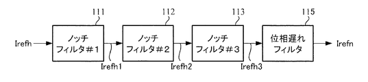
- the specific frequency band removing unit 110 has a configuration in which three notch filters 111, 112, and 113 are connected in series, and a phase delay filter 115 is connected to the final stage. It has become.
- the attenuation frequencies of the notch filters 111, 112 and 113 are fs_trq / 2 and fs_trq, respectively.
- fs_trq ⁇ 3/2.
- the attenuation frequency refers to a frequency having the smallest amplitude in the amplitude characteristics of the filter, and is sometimes called a notch frequency, a center frequency, or the like.
- Each of the notch filters 111 to 113 is designed as a secondary filter, and the frequency characteristic is represented by the following transfer function G when the attenuation frequency is fe .
- s is a Laplace operator
- ⁇ n and ⁇ d are attenuation coefficients.
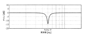
- the amplitude characteristic in this case is an attenuation characteristic as shown in FIG. 6, for example.
- the horizontal axis represents frequency [Hz]
- the vertical axis represents amplitude (gain) [dB]
- the amplitude is the smallest at the attenuation frequency f e (in this example, fs_trq / 2).
- the current command value Itefh is converted.
- the phase delay filter 115 has a first-order or second-order form, and is expressed by a transfer function of the following formula 2 with cut-off frequencies being f n and f d .
- a sample and hold unit exists between the maximum output limiting unit 102 of the torque control system and the specific frequency band removing unit 110 of the current control system. Since the calculation cycle Ts_trq of the torque control system is different from the calculation cycle Ts_cur of the current control system, the current control system cannot receive data (current command value) output from the torque control system in synchronization with the torque control system. For this reason, the data output from the torque control system is stored (sampled) by the sample and hold unit and held until the current control system can receive the data. As a result, data loss can be eliminated. Note that the sample and hold unit may be incorporated into the specific frequency band removing unit 110.
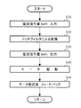
- the current command value Irefh output from the maximum output limiting unit 102 of the torque control system is input to the specific frequency band removing unit 110 of the current control system (step S10).
- the notch filter 1111 receives the current command value Irefh, and converts the current command value Irefh based on the above equation 1 using the held parameter.
- the converted current command value Irefh1 is input to the next-stage notch filter 112, and similarly converted to the current command value Irefh2 based on the above equation 1, and the current command value Irefh2 is further input to the notch filter 113, and similarly Based on Equation 1, the current command value is converted to Irefh3 (step S20).
- the current command value Irefh3 is phase-processed by the final-stage phase delay filter 115 (step S21), and the current command value Irefn thus processed by the specific frequency band removing unit 110 is output (step S30).
- the current command value Irefn is input to the subtraction unit 103, and thereafter, through the same operation as described above, the motor 20 is PWM-driven (step S40), and the motor current value Im detected by the motor current detector 107 is subtracted by the subtraction unit 103. (Step S50).
- FIG. 8 shows the result of applying the present invention to the current command value having the power spectrum shown in FIG.
- FIG. 8 shows the power spectrum of the current command value with the frequency [Hz] on the horizontal axis and the power spectrum [dB] on the vertical axis, as in FIG.
- the steep power spectrum (broken line portion) generated every half frequency of the calculation frequency fs_trq is reduced. I understand.
- the number of notch filters may be changed in accordance with the number of power spectra to be attenuated.
- the specific frequency band removing unit 110 may be configured by only the notch filter 111 and the phase delay filter 115.
- a notch filter having this frequency as an attenuation frequency may be added to the specific frequency band removing unit 110.
- the phase is a bold line in the Bode diagrams shown in FIGS. 9 (A) and 9 (B).
- the specific frequency band removing unit 110 is configured with the primary LPF of 300 Hz
- the frequency characteristics thereof are as shown by the thin lines in FIGS. 9A and 9B. That is, the LPF is set to be equivalent to 300 Hz so that the gain at 500 Hz matches.
- the frequency characteristic for the phase change is shown in FIG. 10, which shows a case where the phase of 50 Hz recovers by about 4.5 degrees.
- the specific frequency band removing unit 110 includes the notch filters 111 to 113 and the phase delay filter 115, but may also include the notch filters 111 to 114 as shown in FIG. 14 (second embodiment). .
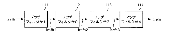
- the specific frequency band removing unit 110 has a configuration in which four notch filters 111, 112, 113, and 114 are connected in series as shown in FIG.
- the attenuation frequencies of the notch filters 111, 112, 113, and 114 are respectively fs_trq / 2.
- Each of the notch filters 111 to 114 is designed as a secondary filter, and the frequency characteristic is represented by the transfer function G of Equation 1 above.
- the amplitude characteristic in this case is an attenuation characteristic as shown in FIG. 15, for example.
- the horizontal axis represents frequency [Hz]
- the vertical axis represents amplitude (gain) [dB]
- the amplitude is the smallest at the attenuation frequency fe (fs_trq / 2 in this example).
- a sample and hold unit exists between the maximum output limiting unit 102 of the torque control system and the specific frequency band removing unit 110 of the current control system.
- the current command value Irefh output from the maximum output limiting unit 102 of the torque control system is input to the specific frequency band removing unit 110 of the current control system (step S10).
- the notch filter 111 receives the current command value Irefh, and converts the current command value Irefh based on the above equation 1 using the held parameter.
- the converted current command value Irefh1 is input to the next-stage notch filter 112, and similarly converted to the current command value Irefh2 based on the above equation 1, and the current command value Irefh2 is further input to the notch filter 113, and similarly
- the current command value Irefh3 is converted to the current command value Irefh3 based on the formula 1, and the current command value Irefh3 is further input to the notch filter 114 at the final stage, and similarly converted to the current command value Irefhn based on the formula 1 (step S20).
- the current command value Irefn processed by the specific frequency band removing unit 110 is output (step S30).
- the current command value Irefn is input to the subtraction unit 103, and thereafter, through the same operation as described above, the motor 20 is PWM-driven (step S40), and the motor current value Im detected by the motor current detector 107 is subtracted by the subtraction unit 103. (Step S50).
- FIG. 17 shows the result of applying the present invention to the current command value having the power spectrum shown in FIG.
- FIG. 17 shows the power spectrum of the current command value with the frequency [Hz] on the horizontal axis and the power spectrum [dB] on the vertical axis, as in FIG.
- the steep power spectrum (broken line) generated at every half frequency of the calculation frequency fs_trq is reduced. I understand.
- the number of notch filters may be changed according to the number of power spectra to be attenuated.
- the specific frequency band removing unit 110 may be configured by only the notch filter 111.
- a notch filter having this frequency as an attenuation frequency may be added to the specific frequency band removing unit 110.
- the phase is a bold line in the Bode diagrams shown in FIGS. 18 (A) and 18 (B).
- the specific frequency band removing unit 110 is configured with the primary LPF of 300 Hz, the frequency characteristics thereof are as shown by the thin lines in FIGS. That is, the LPF is set to be equivalent to 300 Hz so that the gain at 500 Hz matches.
- the frequency characteristic for the phase change is shown in FIG. 19 and shows a case where the phase of 50 Hz recovers by about 9 degrees.
- the specific frequency band removing unit 110 is disposed after the maximum output limiting unit 102, and the current command value Irefh is input to the specific frequency band removing unit 110.
- a brushless motor may be used as a drive source, and the brushless motor is driven and controlled by a vector control system.
- the vector control system will be described below.
- the vector control system of FIG. 24, and the current command value calculating section 220 is provided to correct by calculating the d-axis current command value i d and the q-axis current command value i q, steering the current command value calculating section 220
- the torque Th, the vehicle speed Vs, the motor angle (rotation angle) ⁇ e , and the motor angular velocity ⁇ calculated by the angular velocity calculating unit 226 are input from the rotation sensor 200A connected to the motor 200.
- D-axis current command value i d and the q-axis current command value i q calculated by the current command value calculating unit 220 is input to the 2-phase / 3-phase conversion unit 221, three-phase current in synchronization with the motor angle theta e
- the command values are converted into Iuref, Ivref, and Iwref.
- the three-phase current command values Iuref, Ivref, Iwref are input to the subtractor 222 (222u, 222v, 222w) and current deviations ⁇ Iu, ⁇ Iv from the motor current values Imu, Imv, Imw detected by the motor current detector 225A. , ⁇ Iw is calculated.
- the calculated current deviations ⁇ Iu, ⁇ Iv, ⁇ Iw are input to the PI control unit 223, and the three-phase voltage control command values Vuref, Vvref, Vwref subjected to PI control are input to the PWM control unit 224 and calculated by the PWM control unit 224.
- the motor 200 is driven via the inverter 225 based on each phase duty.
- the motor current detector 225A is provided in the inverter 225, but it can also be detected by a supply line to the motor 200 or the like.
- a motor current detector 225A at the detected three-phase motor current Imu, Imv, 3-phase / 2-phase conversion unit for converting into two phases in synchronism with Imw the motor angle theta e 227 is provided.
- D-axis current command value computed is corrected by the current command value calculating section 220 i d and the q-axis current command value i q is input to the subtraction unit 222 (222d, 222q), 3-phase / 2-phase conversion by the subtraction unit 222
- Current deviations ⁇ i d and ⁇ i q from the two-phase currents Imd and Imq from the unit 227 are calculated.
- the current deviations ⁇ i d and ⁇ i q are input to the PI control unit 221, and the two-phase voltage command values Vd and Vq subjected to PI control are input to the two-phase / three-phase conversion unit 223 and the two-phase / three-phase conversion unit 223. in is converted to a voltage command value Vuref ⁇ Vwref three-phase synchronous motor angle theta e, subsequent operation similar to the case of FIG. 24 is executed.
- the vector control system in FIG. 24 is a three-phase feedback vector control system that feeds back three-phase motor currents Imu, Imv, and Imw
- the vector control system in FIG. 25 is a three-phase motor current Imu, Imv, Imw.
- the present invention can be applied to both the three-phase feedback vector control system and the two-phase feedback vector control system.
Landscapes
- Engineering & Computer Science (AREA)
- Power Engineering (AREA)
- Chemical & Material Sciences (AREA)
- Combustion & Propulsion (AREA)
- Transportation (AREA)
- Mechanical Engineering (AREA)
- Steering Control In Accordance With Driving Conditions (AREA)
- Power Steering Mechanism (AREA)
- Control Of Ac Motors In General (AREA)
Abstract
【課題】トルク制御系の演算周期と電流制御系の演算周期の関係性から発生するパワースペクトルを減衰させることにより、そのパワースペクトルを加振源とする振動や異音等を的確に抑制可能な電動パワーステアリング装置(ベクトル制御系を含む)を提供する。 【解決手段】電流指令値を演算するトルク制御系と、電流指令値に基づいてモータに流れるモータ電流値を制御する電流制御系とを備える電動パワーステアリング装置において、トルク制御系の演算周期が電流制御系の演算周期以上であり、電流制御系は、電流指令値に対してトルク制御系の演算周波数の略2分の1の周波数の少なくとも1つの自然数倍の周波数の成分を減衰させる特定周波数帯域除去部を備え、特定周波数帯域除去部は、減衰周波数を設定するノッチフィルタとで構成され、若しくはノッチフィルタと、減衰される周波数よりも低域側にカットオフ周波数を設定された位相遅れフィルタとで構成されている。
Description
本発明は、少なくとも操舵トルクに基づいて電流指令値を演算するトルク制御系と、電流指令値に基づいてモータ(例えばベクトル制御で駆動制御されるブラシレスモータ)に流れるモータ電流値を制御する電流制御系とを備える電動パワーステアリング装置に関し、特に特定の周波数帯域成分を減衰させると共に、位相遅れを生じない処理機能を有し、振動や異音の発生を的確に抑制する電動パワーステアリング装置に関する。
車両の操舵系をモータの回転力でアシスト制御する電動パワーステアリング装置(EPS)は、モータの駆動力で減速機を介してギア又はベルト等の伝達機構により、ステアリングシャフト或いはラック軸に操舵補助力(アシスト力)を付与するようになっている。かかる従来の電動パワーステアリング装置は、操舵補助力のトルクを正確に発生させるため、モータ電流のフィードバック制御を行っている。フィードバック制御は、電流指令値とモータ電流検出値との差が小さくなるようにモータ印加電圧を調整するものであり、モータ印加電圧の調整は、一般的にPWM(パルス幅変調)制御のデューティの調整で行っている。
電動パワーステアリング装置の一般的な構成を図1に示して説明すると、ハンドル1のコラム軸(ステアリングシャフト、ハンドル軸)2は減速ギア3、ユニバーサルジョイント4a及び4b、ピニオンラック機構5、タイロッド6a,6bを経て、更にハブユニット7a,7bを介して操向車輪8L,8Rに連結されている。また、コラム軸2には、ハンドル1の操舵トルクThを検出するトルクセンサ10及び操舵角θを検出する舵角センサ14が設けられており、ハンドル1の操舵力を補助するモータ20が減速ギア3を介してコラム軸2に連結されている。電動パワーステアリング装置を制御するコントロールユニット(ECU)100には、バッテリ13から電力が供給されると共に、イグニションキー11を経てイグニションキー(IG)信号が入力される。コントロールユニット100は、トルクセンサ10で検出された操舵トルクThと車速センサ12で検出された車速Vsとに基づいてアシスト(操舵補助)指令の電流指令値の演算を行い、電流指令値に補償等を施した電圧制御指令値Vrefによって、EPS用モータ20に供給する電流を制御する。
なお、舵角センサ14は必須のものではなく、配設されていなくても良く、また、モータ20に連結されたレゾルバ等の回転センサから操舵角を取得することも可能である。
コントロールユニット100には、車両の各種情報を授受するCAN(Controller Area Network)50が接続されており、車速VsはCAN50から受信することも可能である。また、コントロールユニット100には、CAN50以外の通信、アナログ/ディジタル信号、電波等を授受する非CAN51も接続可能である。
コントロールユニット100は主としてMCU(CPU、MPU等も含む)で構成されるが、そのMCU内部においてプログラムで実行される一般的な機能を示すと図2のようになる。
図2を参照してコントロールユニット100の機能及び動作を説明すると、トルクセンサ10で検出された操舵トルクTh及び車速センサ12で検出された(若しくはCAN50からの)車速Vsは、電流指令値Irefを演算する電流指令値演算部101に入力される。電流指令値演算部101は、入力された操舵トルクTh及び車速Vsに基づいてアシストマップ等を用いて、モータ20に供給するモータ電流の制御目標値である電流指令値Irefを演算する。電流指令値Irefは過熱保護条件に従って最大電流を制限する最大出力制限部102に入力され、最大電流を制限された電流指令値Irefhが減算部103に入力され、フィードバックされているモータ電流値Imとの電流偏差ΔI(=Irefh-Im)が演算され、その電流偏差ΔIが操舵動作の特性改善のためのPI(比例積分)制御部104に入力される。PI制御部104で特性改善された電圧制御指令値VrefがPWM制御部105に入力され、更に駆動部としてのインバータ106を介してモータ20がPWM駆動される。モータ20のモータ電流値Imはモータ電流検出器107で検出され、減算部103にフィードバックされる。インバータ106は駆動素子としてFETが用いられ、FETのブリッジ回路で構成されている。
このような電動パワーステアリング装置では、装置の構成物や周辺物が共振系を形成し、それら共振系の共振により振動や異音等が発生するので、その抑制が望まれており、種々の対策が提案されている。
例えば、特許第5456576号公報(特許文献1)では、コラムやラック等の電動パワーステアリング装置の構成物若しくは車両前部構造物の剛体部分の機械共振周波数成分を除去する技術が提案されている。特許文献1では、急峻な減衰特性を有するバンドカットフィルタ(バンドストップフィルタ(BPF))若しくはノッチフィルタを用いて、更には2次以上のローパスフィルタ(LPF)を組み合わせて、機械共振周波数成分を除去している。
また、特許第5235536号公報(特許文献2)では、演算により発生するノイズを、アシスト制御終端でLPFを用いて除去している。
しかしながら、電動パワーステアリング装置のコントロールユニット100では、操舵トルクTh及び車速Vsの入力から電流指令値Irefhの出力までの制御系(トルク制御系)と電流指令値Irefhの入力からモータ電流値Imの出力までの制御系(電流制御系)が周期的に行われるが、トルク制御系の演算周期Ts_trq[sec]と電流制御系の演算周期Ts_cur[sec]がTs_trq≧Ts_curの場合、電流制御系での電流指令値の更新周期がトルク制御系での電流指令値の更新周期に引っ張られてしまう。例えば、ハンドルを任意に操舵したときのトルク制御系での電流指令値を電流制御系の演算周期Ts_curでFFT(高速フーリエ変換)解析すると、トルク制御系の演算周波数fs_trq(=1/Ts_trq)の1/2倍の周波数おきに顕著なスペクトルが発生する。図3はその様子を示すグラフで、横軸を周波数[Hz]、縦軸をパワースペクトル[dB]として電流指令値のパワースペクトルを表示したものであり、fs_trq/2の自然数倍の周波数近辺で、破線で示されているように、急峻なパワースペクトルが発生している。これは、fs_trq/2はトルク制御系での電流指令値のサンプリングに対するナイキスト周波数に相当するので、電流制御系での電流指令値において、fs_trq/2の自然数倍の周波数でパワースペクトルが大きくなってしまうのである。ブラシレスモータを使用するベクトル制御系の電動パワーステアリング装置でも全く同様である。
このような急峻なパワースペクトルが発生すると、電動パワーステアリング装置の共振周波数帯(例えば、機械共振の数百Hzから数kHzまで等)の有無に関係なく、急峻なパワースペクトルが加振源となり、振動や異音等を引き起こしてしまう。
特許文献1では、機械共振周波数成分の除去を目的に、狭小な周波数帯域で急峻な減衰特性を有するフィルタを使用しているので、周波数帯域が異なる上述のようなトルク制御系の演算周期と電流制御系の演算周期の関係性から発生するパワースペクトルを減衰させることが困難で、そのパワースペクトルを加振源とする振動や異音等を的確に抑制することができない。また、特許文献2では、演算により発生するノイズをLPFを用いて除去しているので、同様な問題が生じる。
本発明は上述のような事情よりなされたものであり、本発明の目的は、トルク制御系の演算周期と電流制御系の演算周期の関係性から発生するパワースペクトルを減衰させることにより、そのパワースペクトルを加振源とする振動や異音等を的確に抑制することが可能な電動パワーステアリング装置(ベクトル制御系の電動パワーステアリング装置を含む)を提供することにある。
本発明は、少なくとも操舵トルクに基づいて電流指令値を演算するトルク制御系と、前記電流指令値に基づいてモータに流れるモータ電流値を制御する電流制御系とを備える電動パワーステアリング装置に関し、本発明の上記目的は、前記トルク制御系の演算周期が前記電流制御系の演算周期以上であり、前記電流制御系は、前記電流指令値に対して前記トルク制御系の演算周波数の略2分の1の周波数の少なくとも1つの自然数倍の周波数の成分を減衰させる特定周波数帯域除去部を備え、前記特定周波数帯域除去部は、減衰周波数を設定するノッチフィルタで構成されていることにより達成される。
本発明の上記目的は、前記特定周波数帯域除去部が更に、前記ノッチフィルタで減衰される周波数よりも低域側にカットオフ周波数を設定され、前記ノッチフィルタに直列に接続された位相遅れフィルタを備えていることにより、或いは前記ノッチフィルタが、直列に接続された複数のノッチフィルタで構成されていることにより、或いは前記位相遅れフィルタが、1次又は2次の構成であることにより、或いは前記特定周波数帯域除去部が、前記トルク制御系から出力される前記電流指令値、若しくは前記電流指令値と前記モータ電流値の電流偏差を入力することにより、或いは前記モータがブラシレスモータであり、前記ブラシレスモータがベクトル制御で駆動制御されることにより、或いは前記ベクトル制御系が、3相フィードバック式ベクトル制御であることにより、或いは前記ベクトル制御系が、2相フィードバック式ベクトル制御であることにより、より効果的に達成される。
本発明の電動パワーステアリング装置によれば、トルク制御系の演算周波数の1/2倍の周波数の自然数倍の周波数成分を減衰させるノッチフィルタを使用することにより、或いはトルク制御系の演算周波数の1/2倍の周波数の自然数倍の周波数成分を減衰させるノッチフィルタと、位相の回復を図る位相遅れフィルタとを使用することにより、トルク制御系の演算周期と電流制御系の演算周期の関係性から発生するパワースペクトルを減衰させると共に、制御帯域の位相遅れを減少させているので、パワースペクトルを加振源とする振動や異音等を、電動パワーステアリング装置の共振周波数帯域(例えば機械共振の数百Hzから数KHz)の有無によらず、的確に抑制することができる。ベクトル制御系の電動パワーステアリング装置でも同様である。
本発明では、トルク制御系の演算周期Ts_trqと電流制御系の演算周期Ts_curの関係性から発生する急峻なパワースペクトルを、ノッチフィルタのような狭帯域で急峻な減衰特性を有するフィルタを使用して減衰させると共に、位相遅れフィルタを直列に接続して位相遅れのない処理を行っている。具体的には、“Ts_trq≧Ts_cur”の場合にトルク制御系の演算周波数fs_trq(=1/Ts_trq)の1/2倍の周波数おきに発生する急峻なパワースペクトルを、ノッチフィルタを用いて減衰させる。トルク制御系の演算周期Ts_trqと電流制御系の演算周期Ts_curは、例えば、それぞれの制御系での演算量の違い等から異なる周期とすることがあり、トルク制御系の演算量が電流制御系の演算量より大きいとき、“Ts_trq≧Ts_cur”と設定されることがあり、この場合に上記のようなパワースペクトルが発生する。“Ts_trq<Ts_cur”の場合は、トルク制御系でのナイキスト周波数(=演算周波数/2)が電流制御系でのナイキスト周波数より大きいので、上記のようなパワースペクトルの発生は抑えられる。
このような急峻なパワースペクトルが加振源となって振動や異音等を引き起こしてしまうので、ノッチフィルタでピンポイント的に所定周波数帯域を減衰させることにより、他の周波数帯域への影響を抑えて、振動や異音等を的確に抑制することができる。また、ノッチフィルタの後段に位相遅れフィルタを接続し、位相遅れの発生を防止している。なお、バンドストップフィルタのうち、阻止する周波数帯域が特に狭いフィルタがノッチフィルタである。
以下に、本発明の実施の形態を、図面を参照して説明する。
図4は本発明の実施形態の構成例を図2に対応させて示しており、同一構成には同一符号を付して説明は省略する。
本構成例では、最大出力制限部102と減算部103との間に特定周波数帯域除去部110が設けられており、最大出力を制限された電流指令値Irefhが特定周波数帯域除去部110に入力されている。そして、電流指令値演算部101、最大出力制限部102でトルク制御系が構成され、特定周波数帯域除去部110、減算部103、PI制御部104、PWM制御部105、インバータ106及びモータ電流検出器107で電流制御系が構成されている。トルク制御系は演算周期Ts_trqでトルク制御を行い、電流制御系は演算周期Ts_curで電流制御を行い、“Ts_trq≧Ts_cur”の関係となっている。
特定周波数帯域除去部110は例えば図5(第1実施形態)に示されるように、3個のノッチフィルタ111、112、113を直列に接続し、最終段に位相遅れフィルタ115を接続した構成となっている。トルク制御系の演算周波数fs_trq(=1/Ts_trq)の1/2倍の周波数おきに発生するパワースペクトルを減衰させるために、ノッチフィルタ111、112及び113の減衰周波数は、それぞれfs_trq/2、fs_trq及びfs_trq×3/2に設定されている。ここで、減衰周波数とは、フィルタの振幅特性において最も振幅が小さくなる周波数のことを指し、ノッチ周波数、中心周波数等と呼ばれることもある。
各ノッチフィルタ111~113は2次フィルタとして設計されており、周波数特性は、減衰周波数をfeとした場合、下記数1の伝達関数Gで表わされる。

ノッチフィルタ111には、fe=fs_trq/2として予め算出及び設定された数1のパラメータが保持されており、数1に基づいて、入力される電流指令値を変換する。同様に、ノッチフィルタ112及び113にはそれぞれ、fe=fs_trq及びfe=fs_trq×3/2として予め算出及び設定された数1のパラメータが保持されており、数1に基づいて、入力される電流指令値Itefhを変換する。
なお、ノッチフィルタ111~113は、図5に示される順番以外の順番で接続しても良く、周波数fe=fs_trq×2を減衰するノッチフィルタを更に設けても良い。
位相遅れフィルタ115は1次若しくは2次の形態であり、カットオフ周波数をfn、fdとして下記数2の伝達関数で表わされる。

また、下記数3の伝達関数で表わされるフィルタであり、ωn=2πfn、ωd=2πfd、ζn、>0、ζd>0の関係を有し、fd<fnとしたものを2次位相遅れフィルタと定義する。

このような構成において、電流制御系の動作例を図7のフローチャートを参照して説明する。
トルク制御系の最大出力制限部102から出力された電流指令値Irefhは、電流制御系の特定周波数帯域除去部110に入力される(ステップS10)。
特定周波数帯域除去部110では、ノッチフィルタ1111が電流指令値Irefhを入力し、保持しているパラメータを用いて、上記数1に基づいて電流指令値Irefhを変換する。変換された電流指令値Irefh1は次段のノッチフィルタ112に入力され、同様に上記数1に基づいて電流指令値Irefh2に変換され、電流指令値Irefh2は更にノッチフィルタ113に入力され、同様に上記数1に基づいて電流指令値Irefh3に変換される(ステップS20)。電流指令値Irefh3は、最終段の位相遅れフィルタ115で位相処理され(ステップS21)、このように特定周波数帯域除去部110で処理された電流指令値Irefnが出力される(ステップS30)。電流指令値Irefnは減算部103に入力され、その後は前述と同様の動作を経て、モータ20がPWM駆動され(ステップS40)、モータ電流検出器107で検出されたモータ電流値Imが減算部103にフィードバックされる(ステップS50)。
以上の動作が、演算周期Ts_curで繰り返される。
本発明を、図3に示されるパワースペクトルを有する電流指令値に適用した結果を図8に示す。図8は、図3と同様に、横軸を周波数[Hz]、縦軸をパワースペクトル[dB]として電流指令値のパワースペクトルを表示したものである。図3で示されるパワースペクトルと図8で示されるパワースペクトルを比べると、演算周波数fs_trqの1/2倍の周波数おきに発生している急峻なパワースペクトル(破線の箇所)が低減されていることが分かる。
なお、上述ではノッチフィルタを3個備えているが、減衰させたいパワースペクトルの数に合わせて、ノッチフィルタの数を変えても良い。例えば、周波数fs_trq/2でのパワースペクトルが顕著に大きく、このパワースペクトルのみを減衰させたい場合は、特定周波数帯域除去部110をノッチフィルタ111のみと位相遅れフィルタ115で構成すれば良い。或いは、周波数fs_trq×5/2でのパワースペクトルも減衰させたい場合は、本周波数を減衰周波数とするノッチフィルタを特定周波数帯域除去部110に追加すれば良い。
次に、ノッチフィルタとLPFを用いる場合の効果の相違を説明する。
トルク制御系の周期を1ms(fs_trq = 1kHz)、減衰周波数をfs_trq×1/2 = 500Hzとし、特定周波数帯域除去部110を500Hzのノッチフィルタと1次の位相遅れフィルタで構成したときのゲイン及び位相は、図9(A)及び(B)に示すボード線図の太線となる。ただし、1次位相遅れフィルタの設定は、例えばカットオフ周波数fn=600Hz、fd=300Hzとし、fd<fe(500Hz)としている。これに対し、1次のLPF300Hzで特定周波数帯域除去部110を構成すると、その周波数特性は図9(A)及び(B)の細線のようになる。つまり、500Hzでのゲインが合致するように、LPF300Hz相当に設定している。位相変化分の周波数特性は図10となり、50Hzの位相が約4.5deg回復する場合を示している。
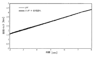
次に、電動パワーステアリング操舵時のシミュレーションの検討結果を図11~図13に示して説明する。ハンドル舵角(トーションバー上側の角度)を図11のように行った場合、操舵トルク(トーションバートルク)の時間応答は図12に示すようになる。図12の太線がノッチフィルタ及び位相遅れによる操舵トルク応答であり、細線が上記LPFを適用した場合の応答であり、グラフが重なり見づらいので、拡大したものを図13に示す。位相が回復できる影響により、振動が低減できることが確認でき、EPSシステムの安定性が改善され、フィードバックループの影響により発生する振動が改善されることを示している。
上述では特定周波数帯域除去部110をノッチフィルタ111~113と位相遅れフィルタ115とで構成しているが、図14に示すようにノッチフィルタ111~114で構成しても良い(第2実施形態)。
即ち、特定周波数帯域除去部110は図14に示されるように、4個のノッチフィルタ111、112、113、114を直列に接続した構成となっている。トルク制御系の演算周波数fs_trq(=1/Ts_trq)の1/2倍の周波数おきに発生するパワースペクトルを減衰させるために、ノッチフィルタ111、112、113及び114の減衰周波数は、それぞれfs_trq/2、fs_trq、fs_trq×3/2及びfs_trq×2に設定されている。
各ノッチフィルタ111~114は2次フィルタとして設計されており、周波数特性は前記数1の伝達関数Gで表わされる。この場合の振幅特性は、例えば図15に示されるような減衰特性となる。図15において、横軸は周波数[Hz]、縦軸は振幅(ゲイン)[dB]であり、減衰周波数fe(本例ではfs_trq/2)で最も振幅が小さくなっている。
ノッチフィルタ111には、fe=fs_trq/2として予め算出及び設定された数1のパラメータが保持されており、数1に基づいて、入力される電流指令値を変換する。同様に、ノッチフィルタ112~114にはそれぞれ、fe=fs_trq、fe=fs_trq×3/2、fe=fs_trq×2として予め算出及び設定された数1のパラメータが保持されており、数1に基づいて、入力される電流指令値Itefhを変換する。なお、前述と同様に、トルク制御系の最大出力制限部102と電流制御系の特定周波数帯域除去部110の間にはサンプルアンドホールド部が存在している。
このような構成において、電流制御系の動作例を図16のフローチャートを参照して説明する。
トルク制御系の最大出力制限部102から出力された電流指令値Irefhは、電流制御系の特定周波数帯域除去部110に入力される(ステップS10)。特定周波数帯域除去部110では、ノッチフィルタ111が電流指令値Irefhを入力し、保持しているパラメータを用いて、上記数1に基づいて電流指令値Irefhを変換する。変換された電流指令値Irefh1は次段のノッチフィルタ112に入力され、同様に上記数1に基づいて電流指令値Irefh2に変換され、電流指令値Irefh2は更にノッチフィルタ113に入力され、同様に上記数1に基づいて電流指令値Irefh3に変換され、電流指令値Irefh3は更に最終段のノッチフィルタ114に入力され、同様に上記数1に基づいて電流指令値Irefhnに変換される(ステップS20)。このように特定周波数帯域除去部110で処理された電流指令値Irefnが出力される(ステップS30)。電流指令値Irefnは減算部103に入力され、その後は前述と同様の動作を経て、モータ20がPWM駆動され(ステップS40)、モータ電流検出器107で検出されたモータ電流値Imが減算部103にフィードバックされる(ステップS50)。
以上の動作が、演算周期Ts_curで繰り返される。
本発明を、図3に示されるパワースペクトルを有する電流指令値に適用した結果を図17に示す。図17は、図3と同様に、横軸を周波数[Hz]、縦軸をパワースペクトル[dB]として電流指令値のパワースペクトルを表示したものである。図3で示されるパワースペクトルと図17で示されるパワースペクトルを比べると、演算周波数fs_trqの1/2倍の周波数おきに発生している急峻なパワースペクトル(破線の箇所)が低減されていることが分かる。
なお、上述ではノッチフィルタを4個備えているが、減衰させたいパワースペクトルの数に合わせて、ノッチフィルタの数を変えても良い。例えば、周波数fs_trq/2でのパワースペクトルが顕著に大きく、このパワースペクトルのみを減衰させたい場合は、特定周波数帯域除去部110をノッチフィルタ111のみで構成すれば良い。或いは、周波数fs_trq×5/2でのパワースペクトルも減衰させたい場合は、本周波数を減衰周波数とするノッチフィルタを特定周波数帯域除去部110に追加すれば良い。
次に、ノッチフィルタとLPFを用いる場合の効果の相違を説明する。
トルク制御系の周期を1ms(fs_trq = 1kHz)、減衰周波数をfs_trq×1/2 = 500Hzとし、特定周波数帯域除去部110を500Hzのノッチフィルタと1次の位相遅れフィルタで構成したときのゲイン及び位相は、図18(A)及び(B)に示すボード線図の太線となる。これに対し、1次のLPF300Hzで特定周波数帯域除去部110を構成すると、その周波数特性は図18(A)及び(B)の細線のようになる。つまり、500Hzでのゲインが合致するように、LPF300Hz相当に設定している。位相変化分の周波数特性は図19となり、50Hzの位相が約9deg回復する場合を示している。
次に、電動パワーステアリング操舵時のシミュレーションの検討結果を図20~図22に示して説明する。ハンドル舵角(トーションバー上側の角度)を図20のように行った場合、操舵トルク(トーションバートルク)の時間応答は図21に示すようになる。図21の太線がノッチフィルタによる操舵トルク応答であり、細線が上記LPFを適用した場合の応答であり、グラフが重なり見づらいので、拡大したものを図22に示す。位相が回復できる影響により、振動が低減できることが確認でき、EPSシステムの安定性が改善され、フィードバックループの影響により発生する振動が改善されることを示している。
上述の第1及び第2実施形態では、特定周波数帯域除去部110を最大出力制限部102の後段に配設し、特定周波数帯域除去部110に電流指令値Irefhを入力しているが、図23に示すように減算部103の後段に配設し、電流偏差ΔIを入力するようにしても良い(第3実施形態)。
本発明に係る電動パワーステアリング装置は駆動源としてブラシレスモータが使用されても良く、ブラシレスモータはベクトル制御系で駆動制御される。以下にベクトル制御系について説明する。
図24のベクトル制御系では、d軸電流指令値id及びq軸電流指令値iqを演算して補正する電流指令値演算部220が設けられており、電流指令値演算部220には操舵トルクTh、車速Vs、モータ200に連結された回転センサ200Aからモータ角度(回転角度)θe、角速度演算部226で演算されたモータ角速度ωが入力されている。電流指令値演算部220で演算されたd軸電流指令値id及びq軸電流指令値iqは2相/3相変換部221に入力され、モータ角度θeに同期して3相の電流指令値Iuref,Ivref,Iwrefに変換される。3相の電流指令値Iuref,Ivref,Iwrefは減算部222(222u,222v,222w)に入力され、モータ電流検出器225Aで検出されたモータ電流値Imu,Imv,Imwとの電流偏差ΔIu,ΔIv,ΔIwが算出される。算出された電流偏差ΔIu,ΔIv,ΔIwはPI制御部223に入力され、PI制御された3相の電圧制御指令値Vuref,Vvref,VwrefがPWM制御部224に入力され、PWM制御部224で演算された各相dutyに基づいてインバータ225を介してモータ200が駆動される。
なお、図24では、モータ電流検出器225Aはインバータ225内に設けられているが、モータ200への供給線等でも検出可能である。
また、図25のベクトル制御系では、モータ電流検出器225Aで検出された3相のモータ電流Imu,Imv,Imwをモータ角度θeに同期して2相に変換する3相/2相変換部227が設けられている。電流指令値演算部220で演算され補正されたd軸電流指令値id及びq軸電流指令値iqは減算部222(222d、222q)に入力され、減算部222で3相/2相変換部227からの2相の電流Imd,Imqとの電流偏差Δid,Δiqが算出される。電流偏差Δid,ΔiqはPI制御部221に入力され、PI制御された2相の電圧指令値Vd及びVqが2相/3相変換部223に入力され、2相/3相変換部223でモータ角度θeに同期して3相の電圧指令値Vuref~Vwrefに変換され、以降は図24の場合と同様な動作が実行される。
図24のベクトル制御系は、3相のモータ電流Imu,Imv,Imwがフィードバックされる3相フィードバック式ベクトル制御系であり、図25のベクトル制御系は、3相のモータ電流Imu,Imv,Imwが2相電流Imd,Imqに変換されてフィードバックされる2相フィードバック式ベクトル制御系である。本発明は、上記3相フィードバック式ベクトル制御系及び2相フィードバック式ベクトル制御系のいずれにも適用できる。
1 ハンドル
2 コラム軸(ステアリングシャフト、ハンドル軸)
10 トルクセンサ
12 車速センサ
20、200 モータ
100 コントロールユニット(ECU)
101、220 電流指令値演算部
102 最大出力制限部
104、223 PI制御部
105、224 PWM制御部
106、225 インバータ
107 モータ電流検出器
110 特定周波数帯域除去部
111~114 ノッチフィルタ
115 位相遅れフィルタ
2 コラム軸(ステアリングシャフト、ハンドル軸)
10 トルクセンサ
12 車速センサ
20、200 モータ
100 コントロールユニット(ECU)
101、220 電流指令値演算部
102 最大出力制限部
104、223 PI制御部
105、224 PWM制御部
106、225 インバータ
107 モータ電流検出器
110 特定周波数帯域除去部
111~114 ノッチフィルタ
115 位相遅れフィルタ
Claims (8)
- 少なくとも操舵トルクに基づいて電流指令値を演算するトルク制御系と、前記電流指令値に基づいてモータに流れるモータ電流値を制御する電流制御系とを備える電動パワーステアリング装置において、
前記トルク制御系の演算周期が前記電流制御系の演算周期以上であり、
前記電流制御系は、前記電流指令値に対して前記トルク制御系の演算周波数の略2分の1の周波数の少なくとも1つの自然数倍の周波数の成分を減衰させる特定周波数帯域除去部を備え、
前記特定周波数帯域除去部は、減衰周波数を設定するノッチフィルタで構成されていることを特徴とする電動パワーステアリング装置。 - 前記特定周波数帯域除去部は更に、前記ノッチフィルタで減衰される周波数よりも低域側にカットオフ周波数を設定され、前記ノッチフィルタに直列に接続された位相遅れフィルタを備えている請求項1に記載の電動パワーステアリング装置。
- 前記ノッチフィルタが、直列に接続された複数のノッチフィルタで構成されている請求項1又は2に記載の電動パワーステアリング装置。
- 前記位相遅れフィルタが、1次又は2次の構成である請求項2に記載の電動パワーステアリング装置。
- 前記特定周波数帯域除去部は、前記トルク制御系から出力される前記電流指令値、若しくは前記電流指令値と前記モータ電流値の電流偏差を入力する請求項1乃至4のいずれかに記載の電動パワーステアリング装置。
- 前記モータがブラシレスモータであり、前記ブラシレスモータがベクトル制御で駆動制御される請求項1乃至5のいずれかに記載の電動パワーステアリング装置。
- 前記ベクトル制御系が、3相フィードバック式ベクトル制御である請求項6に記載の電動パワーステアリング装置。
- 前記ベクトル制御系が、2相フィードバック式ベクトル制御である請求項6に記載の電動パワーステアリング装置。
Priority Applications (4)
| Application Number | Priority Date | Filing Date | Title |
|---|---|---|---|
| US15/738,370 US10046790B2 (en) | 2016-05-12 | 2017-05-12 | Electric power steering apparatus |
| JP2017556997A JP6274377B1 (ja) | 2016-05-12 | 2017-05-12 | 電動パワーステアリング装置 |
| EP17796241.2A EP3315387B1 (en) | 2016-05-12 | 2017-05-12 | Electric power steering apparatus |
| CN201780028813.3A CN109153409A (zh) | 2016-05-12 | 2017-05-12 | 电动助力转向装置 |
Applications Claiming Priority (6)
| Application Number | Priority Date | Filing Date | Title |
|---|---|---|---|
| JP2016095925 | 2016-05-12 | ||
| JP2016095926 | 2016-05-12 | ||
| JP2016095924 | 2016-05-12 | ||
| JP2016-095926 | 2016-05-12 | ||
| JP2016-095925 | 2016-05-12 | ||
| JP2016-095924 | 2016-05-12 |
Publications (1)
| Publication Number | Publication Date |
|---|---|
| WO2017195883A1 true WO2017195883A1 (ja) | 2017-11-16 |
Family
ID=60266581
Family Applications (1)
| Application Number | Title | Priority Date | Filing Date |
|---|---|---|---|
| PCT/JP2017/017980 Ceased WO2017195883A1 (ja) | 2016-05-12 | 2017-05-12 | 電動パワーステアリング装置 |
Country Status (5)
| Country | Link |
|---|---|
| US (1) | US10046790B2 (ja) |
| EP (1) | EP3315387B1 (ja) |
| JP (1) | JP6274377B1 (ja) |
| CN (1) | CN109153409A (ja) |
| WO (1) | WO2017195883A1 (ja) |
Cited By (3)
| Publication number | Priority date | Publication date | Assignee | Title |
|---|---|---|---|---|
| JP2019193464A (ja) * | 2018-04-26 | 2019-10-31 | 株式会社デンソー | ステアリング制御装置 |
| CN111038576A (zh) * | 2018-10-11 | 2020-04-21 | 操纵技术Ip控股公司 | 电动助力转向系统中的抖动噪声管理 |
| US20210276612A1 (en) * | 2020-03-09 | 2021-09-09 | Nidec Corporation | Control device and control method for use in electric power steering device, and motor module |
Families Citing this family (7)
| Publication number | Priority date | Publication date | Assignee | Title |
|---|---|---|---|---|
| JP6351834B2 (ja) * | 2015-04-06 | 2018-07-04 | 三菱電機株式会社 | アクチュエータの制御装置、アクチュエータ、バルブ駆動装置およびアクチュエータの異常検知方法 |
| JP7247508B2 (ja) * | 2018-09-28 | 2023-03-29 | 日本電産株式会社 | ステアリング制御装置およびパワーステアリング装置 |
| CN113795796A (zh) * | 2019-05-13 | 2021-12-14 | 三菱电机株式会社 | 控制系统及电动机控制装置 |
| CN110937051B (zh) * | 2019-11-04 | 2020-12-15 | 北京理工大学 | 一种实时测量自行车骑行者输出功率的方法 |
| CN113395021B (zh) * | 2021-07-13 | 2022-06-10 | 北京航空航天大学 | 一种基于Buck变换器的无刷直流电机低功耗驱动系统及方法 |
| CN115214764B (zh) * | 2021-12-20 | 2023-08-15 | 广州汽车集团股份有限公司 | 转向控制方法、装置、器件及可读存储介质 |
| CN118744758B (zh) * | 2024-06-20 | 2025-12-05 | 重庆长安汽车股份有限公司 | 车辆的控制方法、装置、电子设备以及存储介质 |
Citations (3)
| Publication number | Priority date | Publication date | Assignee | Title |
|---|---|---|---|---|
| JP2006340446A (ja) * | 2005-05-31 | 2006-12-14 | Hitachi Via Mechanics Ltd | ディジタルサーボ制御装置及びレーザ加工装置 |
| JP2014141173A (ja) * | 2013-01-24 | 2014-08-07 | Toyota Motor Corp | 車両の操舵制御装置 |
| WO2017030067A1 (ja) * | 2015-08-19 | 2017-02-23 | 日本精工株式会社 | 電動パワーステアリング装置 |
Family Cites Families (6)
| Publication number | Priority date | Publication date | Assignee | Title |
|---|---|---|---|---|
| US6107767A (en) * | 1998-03-20 | 2000-08-22 | Trw Inc. | Electric assist steering system having an improved motor current controller with notch filter |
| WO2001047762A1 (en) * | 1999-12-29 | 2001-07-05 | Delphi Technologies, Inc. | Method and system for improving motor vehicle stability incorporating an electric power steering system |
| JP5040420B2 (ja) * | 2007-05-07 | 2012-10-03 | 株式会社ジェイテクト | 電動パワーステアリング装置 |
| JP5235536B2 (ja) | 2008-07-03 | 2013-07-10 | 三菱電機株式会社 | 電動パワーステアリング制御装置 |
| JP5456576B2 (ja) * | 2010-05-24 | 2014-04-02 | 三菱電機株式会社 | 電動パワーステアリング装置 |
| CN105083370B (zh) * | 2014-05-09 | 2018-01-16 | 现代摩比斯株式会社 | Mdps的补偿控制装置 |
-
2017
- 2017-05-12 EP EP17796241.2A patent/EP3315387B1/en active Active
- 2017-05-12 CN CN201780028813.3A patent/CN109153409A/zh active Pending
- 2017-05-12 WO PCT/JP2017/017980 patent/WO2017195883A1/ja not_active Ceased
- 2017-05-12 US US15/738,370 patent/US10046790B2/en active Active
- 2017-05-12 JP JP2017556997A patent/JP6274377B1/ja not_active Expired - Fee Related
Patent Citations (3)
| Publication number | Priority date | Publication date | Assignee | Title |
|---|---|---|---|---|
| JP2006340446A (ja) * | 2005-05-31 | 2006-12-14 | Hitachi Via Mechanics Ltd | ディジタルサーボ制御装置及びレーザ加工装置 |
| JP2014141173A (ja) * | 2013-01-24 | 2014-08-07 | Toyota Motor Corp | 車両の操舵制御装置 |
| WO2017030067A1 (ja) * | 2015-08-19 | 2017-02-23 | 日本精工株式会社 | 電動パワーステアリング装置 |
Cited By (6)
| Publication number | Priority date | Publication date | Assignee | Title |
|---|---|---|---|---|
| JP2019193464A (ja) * | 2018-04-26 | 2019-10-31 | 株式会社デンソー | ステアリング制御装置 |
| JP7095380B2 (ja) | 2018-04-26 | 2022-07-05 | 株式会社デンソー | ステアリング制御装置 |
| CN111038576A (zh) * | 2018-10-11 | 2020-04-21 | 操纵技术Ip控股公司 | 电动助力转向系统中的抖动噪声管理 |
| US11511795B2 (en) | 2018-10-11 | 2022-11-29 | Steering Solutions Ip Holding Corporation | Dither noise management in electric power steering systems |
| US20210276612A1 (en) * | 2020-03-09 | 2021-09-09 | Nidec Corporation | Control device and control method for use in electric power steering device, and motor module |
| US11807315B2 (en) * | 2020-03-09 | 2023-11-07 | Nidec Corporation | Control device and control method for use in electric power steering device, and motor module |
Also Published As
| Publication number | Publication date |
|---|---|
| EP3315387A1 (en) | 2018-05-02 |
| EP3315387A4 (en) | 2018-12-12 |
| US10046790B2 (en) | 2018-08-14 |
| JP6274377B1 (ja) | 2018-02-07 |
| EP3315387B1 (en) | 2019-12-25 |
| US20180178828A1 (en) | 2018-06-28 |
| JPWO2017195883A1 (ja) | 2018-05-24 |
| CN109153409A (zh) | 2019-01-04 |
Similar Documents
| Publication | Publication Date | Title |
|---|---|---|
| JP6274377B1 (ja) | 電動パワーステアリング装置 | |
| JP6658995B2 (ja) | モータ制御装置及びそれを搭載した電動パワーステアリング装置 | |
| JP6222411B2 (ja) | 電動パワーステアリング装置 | |
| JP6566075B2 (ja) | 電動パワーステアリング装置 | |
| JP6597824B2 (ja) | 電動パワーステアリング装置 | |
| JP5935960B2 (ja) | 電動パワーステアリング装置 | |
| JP6471834B2 (ja) | 電動パワーステアリング装置 | |
| JP2008296877A (ja) | 電動パワーステアリング装置 | |
| JP2017127066A (ja) | モータ制御装置及びそれを搭載した電動パワーステアリング装置 | |
| JPWO2014103693A1 (ja) | モータ制御装置およびモータ制御方法 | |
| JP2018007454A (ja) | モータ制御装置及びそれを搭載した電動パワーステアリング装置 | |
| JP6697790B2 (ja) | 電動パワーステアリング装置および電動パワーステアリングの制御方法 | |
| JP6716031B2 (ja) | 電動パワーステアリング装置および電動パワーステアリングの制御方法 | |
| JP2017175834A (ja) | モータ制御装置及びそれを搭載した電動パワーステアリング装置 | |
| JP2017158245A (ja) | モータ制御装置及びそれを搭載した電動パワーステアリング装置 |
Legal Events
| Date | Code | Title | Description |
|---|---|---|---|
| ENP | Entry into the national phase |
Ref document number: 2017556997 Country of ref document: JP Kind code of ref document: A |
|
| WWE | Wipo information: entry into national phase |
Ref document number: 15738370 Country of ref document: US |
|
| WWE | Wipo information: entry into national phase |
Ref document number: 2017796241 Country of ref document: EP |
|
| NENP | Non-entry into the national phase |
Ref country code: DE |