WO2017196122A1 - 무선 전력 송신 장치 및 그 제어 방법 - Google Patents
무선 전력 송신 장치 및 그 제어 방법 Download PDFInfo
- Publication number
- WO2017196122A1 WO2017196122A1 PCT/KR2017/004940 KR2017004940W WO2017196122A1 WO 2017196122 A1 WO2017196122 A1 WO 2017196122A1 KR 2017004940 W KR2017004940 W KR 2017004940W WO 2017196122 A1 WO2017196122 A1 WO 2017196122A1
- Authority
- WO
- WIPO (PCT)
- Prior art keywords
- signal
- wave
- patch antenna
- target
- wireless power
- Prior art date
- Legal status (The legal status is an assumption and is not a legal conclusion. Google has not performed a legal analysis and makes no representation as to the accuracy of the status listed.)
- Ceased
Links
Images


Classifications
-
- H—ELECTRICITY
- H02—GENERATION; CONVERSION OR DISTRIBUTION OF ELECTRIC POWER
- H02J—ELECTRIC POWER NETWORKS; CIRCUIT ARRANGEMENTS OR SYSTEMS FOR SUPPLYING OR DISTRIBUTING ELECTRIC POWER; SYSTEMS FOR STORING ELECTRIC ENERGY
- H02J50/00—Circuit arrangements or systems for wireless supply or distribution of electric power
- H02J50/20—Circuit arrangements or systems for wireless supply or distribution of electric power using microwaves or radio frequency waves
-
- H—ELECTRICITY
- H01—ELECTRIC ELEMENTS
- H01Q—ANTENNAS, i.e. RADIO AERIALS
- H01Q21/00—Antenna arrays or systems
- H01Q21/06—Arrays of individually energised antenna units similarly polarised and spaced apart
- H01Q21/061—Two dimensional planar arrays
- H01Q21/065—Patch antenna array
-
- H—ELECTRICITY
- H01—ELECTRIC ELEMENTS
- H01Q—ANTENNAS, i.e. RADIO AERIALS
- H01Q3/00—Arrangements for changing or varying the orientation or the shape of the directional pattern of the waves radiated from an antenna or antenna system
- H01Q3/26—Arrangements for changing or varying the orientation or the shape of the directional pattern of the waves radiated from an antenna or antenna system varying the relative phase or relative amplitude of energisation between two or more active radiating elements; varying the distribution of energy across a radiating aperture
- H01Q3/28—Arrangements for changing or varying the orientation or the shape of the directional pattern of the waves radiated from an antenna or antenna system varying the relative phase or relative amplitude of energisation between two or more active radiating elements; varying the distribution of energy across a radiating aperture varying the amplitude
-
- H—ELECTRICITY
- H01—ELECTRIC ELEMENTS
- H01Q—ANTENNAS, i.e. RADIO AERIALS
- H01Q3/00—Arrangements for changing or varying the orientation or the shape of the directional pattern of the waves radiated from an antenna or antenna system
- H01Q3/26—Arrangements for changing or varying the orientation or the shape of the directional pattern of the waves radiated from an antenna or antenna system varying the relative phase or relative amplitude of energisation between two or more active radiating elements; varying the distribution of energy across a radiating aperture
- H01Q3/30—Arrangements for changing or varying the orientation or the shape of the directional pattern of the waves radiated from an antenna or antenna system varying the relative phase or relative amplitude of energisation between two or more active radiating elements; varying the distribution of energy across a radiating aperture varying the relative phase between the radiating elements of an array
- H01Q3/34—Arrangements for changing or varying the orientation or the shape of the directional pattern of the waves radiated from an antenna or antenna system varying the relative phase or relative amplitude of energisation between two or more active radiating elements; varying the distribution of energy across a radiating aperture varying the relative phase between the radiating elements of an array by electrical means
- H01Q3/36—Arrangements for changing or varying the orientation or the shape of the directional pattern of the waves radiated from an antenna or antenna system varying the relative phase or relative amplitude of energisation between two or more active radiating elements; varying the distribution of energy across a radiating aperture varying the relative phase between the radiating elements of an array by electrical means with variable phase-shifters
-
- H—ELECTRICITY
- H01—ELECTRIC ELEMENTS
- H01Q—ANTENNAS, i.e. RADIO AERIALS
- H01Q9/00—Electrically-short antennas having dimensions not more than twice the operating wavelength and consisting of conductive active radiating elements
- H01Q9/04—Resonant antennas
- H01Q9/0407—Substantially flat resonant element parallel to ground plane, e.g. patch antenna
-
- H—ELECTRICITY
- H02—GENERATION; CONVERSION OR DISTRIBUTION OF ELECTRIC POWER
- H02J—ELECTRIC POWER NETWORKS; CIRCUIT ARRANGEMENTS OR SYSTEMS FOR SUPPLYING OR DISTRIBUTING ELECTRIC POWER; SYSTEMS FOR STORING ELECTRIC ENERGY
- H02J50/00—Circuit arrangements or systems for wireless supply or distribution of electric power
- H02J50/20—Circuit arrangements or systems for wireless supply or distribution of electric power using microwaves or radio frequency waves
- H02J50/23—Circuit arrangements or systems for wireless supply or distribution of electric power using microwaves or radio frequency waves characterised by the type of transmitting antennas, e.g. directional array antennas or Yagi antennas
-
- H—ELECTRICITY
- H02—GENERATION; CONVERSION OR DISTRIBUTION OF ELECTRIC POWER
- H02J—ELECTRIC POWER NETWORKS; CIRCUIT ARRANGEMENTS OR SYSTEMS FOR SUPPLYING OR DISTRIBUTING ELECTRIC POWER; SYSTEMS FOR STORING ELECTRIC ENERGY
- H02J50/00—Circuit arrangements or systems for wireless supply or distribution of electric power
- H02J50/40—Circuit arrangements or systems for wireless supply or distribution of electric power using two or more transmitting or receiving devices
- H02J50/402—Circuit arrangements or systems for wireless supply or distribution of electric power using two or more transmitting or receiving devices the two or more transmitting or the two or more receiving devices being integrated in the same unit, e.g. power mats with several coils or antennas with several sub-antennas
-
- H—ELECTRICITY
- H02—GENERATION; CONVERSION OR DISTRIBUTION OF ELECTRIC POWER
- H02J—ELECTRIC POWER NETWORKS; CIRCUIT ARRANGEMENTS OR SYSTEMS FOR SUPPLYING OR DISTRIBUTING ELECTRIC POWER; SYSTEMS FOR STORING ELECTRIC ENERGY
- H02J50/00—Circuit arrangements or systems for wireless supply or distribution of electric power
- H02J50/90—Circuit arrangements or systems for wireless supply or distribution of electric power involving detection or optimisation of position, e.g. alignment
Definitions
- the present disclosure relates to a wireless power transmission apparatus and a control method thereof. More specifically, the present disclosure relates to a wireless power transmission apparatus and method capable of wirelessly transmitting power to an electronic device.
- Wireless power transmission includes magnetic induction, magnetic resonance, and electromagnetic wave methods, and electromagnetic wave methods have advantages over remote power transmission than other methods.
- Electromagnetic wave method is mainly used for long distance power transmission, and the key is to locate the exact position of the remote power receiver and to transmit power most efficiently.
- a radio frequency (RF) wave In order to charge an electronic device to be charged using an electromagnetic wave method, a radio frequency (RF) wave must be formed in a plurality of directions, and information related to power reception must be received from the electronic device. The location of the electronic device had to be determined using the relevant information. However, it takes a long time to form the RF wave in a plurality of directions and receive power related information. In particular, due to human hazards, high power cannot be transmitted before detection of a charging target. In particular, when the user lifts or wears a small terminal, the position of the terminal may be changed frequently.
- one aspect of the present disclosure is to provide a quick determination of terminal location for effective wireless charging.
- Various embodiments of the present disclosure can provide a wireless power transmission apparatus and a control method thereof capable of quickly determining a location of an electronic device by transmitting a transmission wave, receiving a reflection wave formed by reflecting the transmission wave, and analyzing the same.
- various embodiments of the present disclosure may provide a wireless power transmission apparatus capable of quickly switching transmission of a transmission wave and reception of a reflected wave.
- an apparatus for transmitting wireless power includes a patch antenna and a transmission / reception processing circuit configured to output a first signal to the patch antenna during a first period and to process a second signal output from the patch antenna during a second period.
- the antenna may transmit a transmission wave using the first signal, and the patch antenna may output the second signal to the transmission / reception processing circuit using a reception wave received from the outside.
- an apparatus for transmitting wireless power includes a plurality of patch antennas and a transmission / reception processing circuit for inputting a first signal to a first portion of the plurality of patch antennas and processing a second signal output from a second portion of the plurality of patch antennas. And a first portion of the plurality of patch antennas transmits a transmission wave using the first signal, and a second portion of the plurality of patch antennas receives the second signal using the received wave. It can output to the transmission / reception processing circuit.
- a wireless power transmission apparatus and a control method thereof capable of determining a location of an electronic device by transmitting a transmission wave, receiving a reflection wave formed by reflecting the transmission wave, and analyzing the same.
- a wireless power transmission apparatus capable of quickly switching between transmission of a transmission wave and reception of a reflection wave may be provided. Accordingly, the electronic device or the obstacle can be detected quickly.
- the wireless power transmission device can receive and relay power from another wireless power transmission device, thereby enabling long-range wireless power transmission.
- FIG. 1 is a diagram of a wireless power transmission system according to various embodiments of the present disclosure.
- FIG. 2A illustrates a block diagram of a wireless power transmission apparatus according to various embodiments of the present disclosure.
- 2B is a diagram illustrating a configuration of a wireless power transmission apparatus according to various embodiments of the present disclosure.
- FIG. 3 is a flowchart illustrating a control method of a wireless power transmission apparatus according to various embodiments of the present disclosure.
- FIG. 4 is a block diagram of a transmission and reception processing circuit according to various embodiments of the present disclosure.
- FIG. 5 is a timing diagram illustrating timings of a transmission operation and a reception operation according to various embodiments of the present disclosure.
- 6A is a diagram illustrating a transmission wave formation according to various embodiments of the present disclosure.
- 6B is a timing diagram illustrating timing of transmission and timing of reception according to various embodiments of the present disclosure.
- FIG. 7 is a diagram illustrating a transmission wave formation according to various embodiments of the present disclosure.
- FIG. 8 is a diagram illustrating a transmitting patch antenna and a receiving patch antenna according to various embodiments of the present disclosure.
- FIG. 9 is a flowchart illustrating an operation of a wireless power transmission apparatus according to various embodiments of the present disclosure.
- FIG. 10 is a flowchart illustrating a target detection process according to various embodiments of the present disclosure.
- FIG. 11 is a diagram illustrating a transmission wave and a reception wave according to various embodiments of the present disclosure.
- FIG. 12 is a flowchart illustrating a target detection process according to another embodiment of the present invention.
- FIG. 13 is a diagram illustrating a transmission wave and a reception wave according to various embodiments of the present disclosure.
- FIG. 14 is a flowchart illustrating an operation change process according to various embodiments of the present disclosure.
- 15 is a flowchart illustrating a control method of a wireless power transmission apparatus according to various embodiments of the present disclosure.
- 16A, 16B, 16C, and 16D illustrate diagrams for describing changes of a transmission patch antenna and a reception patch antenna according to various embodiments of the present disclosure.
- 17A, 17B, and 17C illustrate diagrams for describing arrangement of a patch antenna for transmission and a patch antenna for reception according to various embodiments of the present disclosure.
- FIG. 18 is a flowchart illustrating a control method of a wireless power transmission apparatus according to various embodiments of the present disclosure.
- 19 is a diagram illustrating an arrangement of a patch antenna for transmission and a patch antenna for reception according to various embodiments of the present disclosure.
- FIG. 20 is a diagram illustrating a power relay according to various embodiments of the present disclosure.
- 21 is a block diagram of a wireless power transmission apparatus according to various embodiments of the present disclosure.
- 22 is a circuit diagram of a wireless power transmission apparatus according to various embodiments of the present disclosure.
- 23A, 23B, and 23C illustrate a patch antenna of a wireless power transmission apparatus according to various embodiments of the present disclosure.
- the expression “device configured to” may mean that the device “can” together with other devices or components.
- processor configured (or configured to) perform A, B, and C may be implemented by executing a dedicated processor (eg, an embedded processor) to perform its operation, or one or more software programs stored in a memory device. It may mean a general purpose processor (eg, a CPU or an application processor) capable of performing the corresponding operations.
- the wireless power transmitter or electronic device may be, for example, a smartphone, a tablet PC, a mobile phone, a video phone, an e-book reader, a desktop PC, a laptop PC, a netbook computer, a workstation, It may include at least one of a server, a PDA, a portable multimedia player (PMP), an MP3 player, a medical device, a camera, and a wearable device.
- Wearable devices may be accessory (e.g. watches, rings, bracelets, anklets, necklaces, eyeglasses, contact lenses, or head-mounted-devices (HMDs), textiles or clothing integrated (e.g.
- a wireless power transmitter or electronic device may be, for example, a television, a digital video disk (DVD). ), Audio, refrigerator, air conditioner, cleaner, oven, microwave oven, washing machine, air purifier, set-top box, home automation control panel, security control panel, media box, game console, electronic dictionary, electronic key, camcorder, or It may include at least one of the electronic picture frame.
- a wireless power transmitter or electronic device may be, for example, a television, a digital video disk (DVD).
- Audio refrigerator, air conditioner, cleaner, oven, microwave oven, washing machine, air purifier, set-top box, home automation control panel, security control panel, media box, game console, electronic dictionary, electronic key, camcorder, or It may include at least one of the electronic picture frame.
- the wireless power transmission device or electronic device may include a variety of medical devices (e.g., various portable medical devices such as blood glucose meters, heart rate monitors, blood pressure meters, or body temperature meters), magnetic resonance angiography (MRA), MRI ( magnetic resonance imaging (CT), computed tomography (CT), imagers, or ultrasounds), navigation devices, global navigation satellite systems (GNSS), event data recorders (EDRs), flight data recorders (FDRs), automotive infotainment devices , Electronic equipment for ships (e.g., ship navigation devices, gyro compasses, etc.), avionics, security devices, vehicle head units, industrial or home robots, drones, ATMs in financial institutions, shops Point of sales, or Internet of Things devices (e.g.
- a wireless power transmission device or electronic device may be a piece of furniture, a building / structure or automobile, an electronic board, an electronic signature receiving device, a projector, or various measurement devices (eg, : Water, electricity, gas, or radio wave measuring instrument).
- the wireless power transmission device or electronic device may be flexible or a combination of two or more of the various devices described above.
- the wireless power transmission device or the electronic device according to the embodiment of the present document is not limited to the above-described devices.
- the term user may refer to a person using an electronic device or a wireless power transmission device or a device (eg, an artificial intelligence electronic device) using the electronic device.
- FIG. 1 is a diagram of a wireless power transmission system according to various embodiments of the present disclosure.
- the apparatus 100 for transmitting power wirelessly may wirelessly transmit power to at least one terminal 150 or 160.
- the apparatus 100 for transmitting power wirelessly may include a plurality of patch antennas 111 to 126.
- the patch antennas 111 to 126 are not limited as long as they are each antennas capable of generating an RF wave. At least one of the amplitude and the phase of the RF wave generated by the patch antennas 111 to 126 may be adjusted by the wireless power transmitter 100.
- the RF wave generated by each of the patch antennas 111 to 126 will be referred to as a sub-RF wave.
- the apparatus 100 for transmitting power wirelessly may adjust at least one of amplitude and phase of each of the sub-RF waves generated by the patch antennas 111 to 126.
- sub-RF waves may interfere with each other.
- the apparatus 100 for transmitting power wirelessly includes at least one of an amplitude and a phase of each of the sub-RF waves generated by the patch antennas 111 to 126 so that the sub-RF waves may constructively interfere with each other at the first point (x1, y1, z1). You can adjust one.
- the apparatus 100 for transmitting power wirelessly may determine that the terminal 150 is located at the first points x1, y1, and z1.
- the first point may be, for example, a point at which an antenna for receiving power of the terminal 150 is located.
- the configuration of the wireless power transmitter 100 to determine the location of the terminal 150 will be described later in more detail.
- the apparatus 100 for transmitting power wirelessly may control the patch antennas 111 to 126 such that the sub-RF waves are constructive interference with each other at the first points x1, y1, and z1.
- controlling the patch antennas 111 to 126 means controlling the magnitude of the signal input to the patch antennas 111 to 126 or adjusting the phase (or delay) of the signal input to the patch antennas 111 to 126. It can mean controlling.
- controlling there is no limitation on the type of beam-forming used in the present invention. RF waves formed by beam-forming may be referred to as pockets of energy.
- the RF wave 130 formed by the sub-RF waves may have a maximum amplitude at the first points x1, y1, and z1, and the terminal 150 may receive wireless power with high transmission efficiency.
- the apparatus 100 for transmitting power wirelessly may determine that the terminal 160 is located at the second points x2, y2, and z2.
- the apparatus 100 for transmitting power wirelessly controls the patch antennas 111 to 126 such that the sub-RF waves are constructive interference at the second points x2, y2, and z2 in order to provide wireless power for charging the terminal 160. can do.
- the RF wave 140 formed by the sub-RF waves may have a maximum amplitude at the second point (x2, y2, z2), and the terminal 160 may receive wireless power with high transmission efficiency. have.
- the apparatus 100 for transmitting power wirelessly may determine the positions of the terminals 150 and 160 and cause the sub-RF waves to become constructive interference at the determined position, thereby performing wireless charging with high transmission efficiency.
- the wireless power transmission apparatus 100 must accurately determine the position of the terminal (150, 160), it is possible to wireless charging of high transmission efficiency.
- FIG. 2A illustrates a block diagram of a wireless power transmission apparatus according to various embodiments of the present disclosure.
- an apparatus for transmitting power wirelessly may include an antenna array 210, a transmit / receive processing circuit 220, a power source 230, and a processor 240.
- the antenna array 210 may form an RF wave.
- the antenna array 210 may include a plurality of patch antennas, each of which may form a sub-RF wave. Power output from the power source 230 may be adjusted by the transmit / receive processing circuit 220 for RF wave formation.
- the transmission / reception processing circuit 220 may include a plurality of elements for controlling power connected to each of the plurality of patch antennas included in the antenna array 210.
- the plurality of devices may include, for example, a phase shifter for adjusting a phase of an electrical signal input to the patch antenna.
- the phase shifter is not limited as long as it can change the phase of the input electrical signal and output the same.
- HMC642 or HMC1113 may be used.
- the amplifier may adjust the amplitude of the received electrical signal.
- the amplifier may be implemented with, for example, a Gain Block Amplifier (GBA).
- GGBA Gain Block Amplifier
- adjusting the delay of the signal may mean that the timing of oscillation from the patch antenna is adjusted, which may mean that the phase of the signal is adjusted.
- Each patch antenna of the antenna array 210 may form a sub-RF wave using the received signal.
- the processor 240 may control the transmit / receive processing circuit 220 such that the sub-RF wave is constructive interference at a specific point. Accordingly, the sub-RF waves may be constructive interference at a specific point, and thus the wireless power transmitter may perform power transmission for the specific point.
- the RF wave formed from the antenna array 210 is called a transmission wave.
- the patch antenna of the antenna array 210 may output a signal based on the RF wave.
- the patch antenna may form an RF wave by using an input electrical signal, and may receive and output an adjacent RF wave and convert it into an electrical signal. That is, the patch antenna may form an RF wave based on the received signal, or may output a signal based on the RF wave.
- the amplitude of the signal output from the patch antenna may also be changed. Accordingly, an electrical signal corresponding to the RF wave may be output from the patch antenna.
- the RF wave output from the antenna array 210 may be reflected by an electronic device or an obstacle and received by the patch antenna again.
- the RF wave reflected by the electronic device or the obstacle and received by the antenna array 210 is called a reflected wave or a received wave.
- another wireless power transmitter may form an RF wave, in which case the RF wave is called a reception wave.
- the transmit / receive processing circuit 220 may process a signal output from the antenna array 210 and output the processed signal to the processor 240.
- the transmit / receive processing circuit 220 may perform filtering, amplification, control of at least one of phase and amplitude, and the like, on the signal output from the patch antenna, which will be described in more detail with reference to FIG. 4.
- the processor 240 may detect an electronic device or an obstacle using a signal processed by the transmission / reception processing circuit 220.
- the processor 240 according to various embodiments of the present disclosure may determine the direction or the location in which the electronic device or the obstacle is located, and may additionally operate using the determined information.
- the apparatus for transmitting power wirelessly may determine at least one of a position and a direction of a target using a difference in time when reflected waves are received at each of the plurality of patch antennas or a phase difference of reflected waves received at each of the plurality of patch antennas. have.
- the processor 240 may control the operation of the overall wireless power transmitter and the operation of the hardware included in the wireless power transmitter.
- 2B is a diagram illustrating a configuration of a wireless power transmission apparatus according to various embodiments of the present disclosure.
- an oscillator 235 may provide an AC waveform signal to a splitter 231.
- the splitter 231 may split the received signal by the number of patch antennas 211 to 214.
- the splitter 231 may transmit each split signal to each of the mixers 251 to 254.
- Each of the signals from splitter 231 may be provided to each of transmit and receive processing circuits 221-224 through each of mixers 251-254.
- Each of the transmission / reception processing circuits 221 to 224 may process the provided signal and provide the received signal to each of the patch antennas 211 to 214.
- the transmission and reception processing circuits 221 to 224 may adjust the phase of the received signal, that is, apply a delay to the signal.
- the transmission / reception processing circuits 221 to 224 may adjust the amplitude of the received signal.
- Each of the transmit / receive processing circuits 221 to 224 may adjust at least one of a phase and an amplitude of the signal under the control of the processor 240, and the processor 240 may adjust at least one of the phase and the amplitude of the signal to be beamformed at a specific point.
- Each of the transmission and reception processing circuits 221 to 224 may be controlled to adjust one. More specifically, the degree of phase adjusted by each of the transmit / receive processing circuits 221 to 224 may be different, and thus, the timing at which the sub-RF wave is oscillated at each of the patch antennas 211 to 214 or the sub-RF to be oscillated. The phases of the wave can be adjusted differently so that beam-forming for a particular point or direction can be formed.
- the processor 240 may further provide additional information, and the additional information may be mixed with the signal from the splitter 231 by each of the mixers 251 to 254. Additional information may be converted into analog form by analog-to-digital converters (ADCs) 261, 263, 265, and 267 and provided to each of the mixers 251 to 254.
- ADCs analog-to-digital converters
- the mixers 251 to 254 may modulate the signal from the oscillator 235 and output the modulated signal to the transmit / receive processing circuits 221 to 224.
- the mixers 251 to 254 may demodulate the signals output from the transmission and reception processing circuits 221 to 224 and output the demodulated signals to the ADCs 262, 264, 266 and 268.
- Each of the patch antennas 211 to 214 may form sub-RF waves using a signal provided from each of the transmission and reception processing circuits 221 to 224.
- an RF wave ie, a transmission wave 291
- the transmission wave 291 may be formed during the first period. That is, the oscillator 235 may provide a signal to the splitter 231 for a first period, and each of the transmission / reception processing circuits 221 to 224 may process the received signal to form the transmission wave 291.
- Each of the patch antennas 211 to 214 may form sub-RF waves using the received signal. Accordingly, the patch antennas 211 to 214 may form sub-RF waves using the signal provided during the first period.
- the transmission wave 291 may travel toward the target 290, and the reflected wave 292 may be generated based on the reflection by the target 290.
- the reflected wave 292 may travel toward the patch antennas 211 to 214.
- the patch antennas 211 to 214 may receive the reflected wave 292 during the second period. That is, the patch antennas 211 to 214 may output an electrical signal to each of the transmission and reception processing circuits 221 to 224 using the received reflected wave 292.
- Each of the transmit / receive processing circuits 221 to 224 may process the received electrical signal and provide it to the ADCs 262, 264, 266, and 268. For example, each of the transmission and reception processing circuits 221 to 224 may adjust at least one of an amplitude and a phase of an input electrical signal to provide the ADCs 262, 264, 266, and 268.
- the processor 240 may control to receive the reflected wave in a specific direction, so that each of the transmission and reception processing circuits 221 to 224 applies a delay to the input electrical signal according to the specific direction, that is, the phase of the electrical signal. Can be adjusted. More specifically, the processor 240 may determine an approximate location of the target 290 and may attempt to more accurately measure the reflected wave 292 from the location.
- the processor 240 may determine the degree of phase adjustment of each of the signals for forming the transmission wave for which beam-forming is performed at the position of the target 290.
- the processor 240 may adjust the phase of the electrical signal output from each of the patch antennas 211 to 214 based on the reflected wave 292 to a degree of phase adjustment for transmission wave formation. Accordingly, the processor 240 may more accurately measure a signal generated from a specific direction, that is, the reflected wave 292.
- the ADCs 262, 264, 266, and 268 may convert the received processed signal into a digital signal and provide the converted signal to the processor 240, and the processor 240 may analyze the characteristic of the reflected wave 292 by analyzing the converted signal. .
- the processor 240 may determine at least one of the presence or absence of the target 290, the type of the target 290, the position of the target 290, and the direction in which the target 290 is located based on the analysis result of the reflected wave 292. have.
- the wireless power transmitter may perform additional operations according to the determination result.
- the apparatus for transmitting power wirelessly may form the transmission wave 291 during the first period, and receive and analyze the reflected wave 292 during the second period. Accordingly, the target related information such as the presence, location, type, direction, etc. of the target 290 may be determined using only the patch antennas 211 to 214 without any additional device.
- the apparatus for transmitting power wirelessly may control some of the patch antennas 211 to 214 to operate to form a transmission wave, and control some of the other to operate to receive a reception wave.
- the wireless power transmission apparatus controls all the patch antennas 211 to 214 to operate for transmission wave formation during the first period, and all patch antennas 211 to 214 receive the received wave during the second period. It may be controlled to operate for.
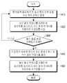
- FIG. 3 is a flowchart illustrating a control method of a wireless power transmission apparatus according to various embodiments of the present disclosure.
- the wireless power transmission apparatus may control to transmit a transmission wave, which is an RF wave, to the target during the first period.
- the wireless power transmission apparatus may transmit and receive at least one of a phase and an amplitude of a signal received from a power source during a first period by a transmission / reception processing circuit to a patch antenna.
- the patch antenna forms an RF wave so that a transmission wave can be transmitted.
- the apparatus for transmitting power wirelessly may control to receive the reflected wave, that is, the received wave, during the second period.
- the wireless power transmitter may adjust and provide at least one of a phase and an amplitude of a signal output from a patch antenna during a second period to a processor.
- the processor may determine at least one of the presence or absence of the target, the type of the target, the position of the target, and the direction in which the target is located based on the received signal. More specifically, the processor can determine the approximate location of the target and attempt to more accurately measure the reflected waves from that location.
- the processor may determine at least one of a phase adjustment degree and an amplitude adjustment degree of each of the signals for forming the transmission wave, which are beam-formed at the target position.
- the processor may more accurately measure a signal generated from a specific direction, that is, a reflected wave, by adjusting the electrical signals output from the patch antennas based on at least one of a phase adjustment degree and an amplitude adjustment degree determined.
- the apparatus for transmitting power wirelessly may operate based on a result of analysis of reflected waves, that is, received waves. For example, the apparatus for transmitting power wirelessly may operate based on at least one of a determined target, a target type, a target position, and a direction in which the target is located. For example, if it is determined that the target is detected, the wireless power transmission apparatus may perform a procedure for determining the type of the target or perform wireless charging. If it is determined that the target is not detected, the apparatus for transmitting power wirelessly may repeatedly perform operations 310 and 320 to determine the presence or absence of the target. For example, when it is determined that the target is a human body, the wireless power transmitter may output a warning.
- the apparatus for transmitting power wirelessly may determine a shape of a target based on an analysis result of a received wave, and determine the type of the target by comparing the shape of the target with a corresponding relationship between a previously stored shape and a kind. have. If it is determined that the type of the target is a human body, the wireless power transmitter may output a warning message. In addition, the wireless power transmitter may control not to form an RF wave in a corresponding direction. If it is determined that the target is a chargeable electronic device, the wireless power transmitter may perform wireless charging. If it is determined that the target is an obstacle, the apparatus for transmitting power wirelessly may repeatedly perform operations 310 and 320 to determine the presence or absence of another target without performing wireless charging. When at least one of the location of the target and the direction in which the target is located is detected, the wireless power transmitter may perform charging by transmitting wireless power in the direction of the location of the target and in the direction in which the target is located.
- FIG. 4 is a block diagram of a transmission and reception processing circuit according to various embodiments of the present disclosure.
- the transmit / receive processing circuit may include a switch 401 capable of switching between a first path capable of receiving a transmission signal and a second path outputting a received signal.
- the switch 401 may connect a transmission signal input terminal to a fixed attenuator 403.
- the switch 401 may, for example, output a signal output from the power source to the fixed attenuator 403.
- the fixed attenuator 403 may attenuate the amplitude of the input signal to a fixed magnitude and output the attenuated signal to the amplifier 405.
- the amplifier 405 may amplify the received signal and output it to the switch 407.
- the switch 407 may be connected to the variable attenuator 409 during the first period and to the amplifier 429 during the second period. During the first period, a signal output from the amplifier 405 may be transmitted to the variable attenuator 409.
- the amplifier 405 may be implemented as a gain block amplifier (GBA).
- the variable attenuator 409 may attenuate the amplitude to a size determined by a processor or the like.
- the processor may determine an amplitude of a signal corresponding to each of the plurality of patch antennas for beamforming, and may output a control signal for adjusting the amplitude to the variable attenuator 409. In this case, the amplitude attenuation degree input for each patch antenna for beamforming may be set differently.
- the variable attenuator 409 may attenuate and output the amplitude of the received signal according to the control signal.
- the processor 240 may differently set the amplitude attenuation of each of the variable attenuators, and thus beamforming may be performed.
- the amplifier 411 may amplify the signal output from the variable attenuator 409 and output the amplified signal to the phase shifter 413.
- the amplifier 411 may be implemented as a gain block amplifier (GBA).
- the phase shifter 413 may perform shifting in a phase determined by a processor or the like. For example, the phase shifter 413 may apply the delay determined by the processor 240 to the input signal and output the received signal.
- the number of phase shifters and patch antennas is exemplary, and the number is not limited.
- the phase shifter may be implemented with, for example, an HMC642 phase shifter or an HMC1113 phase shifter.
- the processor may determine a phase of a signal corresponding to each of the plurality of patch antennas or a delay to be applied to the signal for beamforming, and output a control signal for phase adjustment to the phase shifter 413.
- the phase shifter 413 may adjust and output a phase of the received signal according to the control signal.
- the processor 240 may set different amplitude attenuation levels of the phase shifters, and beamforming may be performed accordingly.
- the phase-adjusted signal may be output to the switch 415.
- the wireless power transmitter may perform beamforming by adjusting only one of a phase and an amplitude of a signal, wherein only one of the variable attenuator 409 or the phase shifter 413 is transmitted and received. It may also be included in the processing circuit.
- the switch 415 may connect the phase shifter 413 to the amplifier 417 in the first period, that is, the transmission operation.
- the amplifier 417 and the amplifier 419 may amplify the signal output from the phase shifter 413 and output the amplified signal to the circulator 421.
- the amplifier 417 may be implemented as a drive amplifier (DA), and the amplifier 419 may be implemented as a high power amplifier (HPA).
- the circulator 421 may cyclically connect an input terminal and an output terminal of the patch antenna. For example, during the first period, the circulator 421 may connect the amplifier 419 to an input terminal of the patch antenna, so that a signal from the amplifier 419 may be provided to the patch antenna. In the meantime, the connection with the output terminal of the patch antenna may be released.
- the patch antenna may form a sub-RF wave based on the input signal.
- at least one of the amplitude and the phase of the signal input to the patch antenna may be adjusted by at least one of the variable attenuator 409 and the phase shifter 413. Accordingly, at least one of the amplitude and the phase of the sub-RF wave formed in the patch antenna may be adjusted.
- the processor may control at least one of the variable attenuator 409 and the phase shifter 413 such that sub-RF waves formed from the plurality of patch antennas are constructively interfered at a particular point.
- the beamforming of the RF wave that is, the transmission wave
- the circulator 421 may connect the output terminal of the patch antenna to the limiter 423.
- a reflected wave may be received at the patch antenna, and the patch antenna may output a signal corresponding to the received reflected wave to the limiter 423.
- the output terminal of the patch antenna may be connected to the limiter 423, and the connection with the input terminal of the patch antenna may be released.
- the limiter 423 may suddenly attenuate the magnitude of the large-scale signal output from the patch antenna when the large reflected wave is received at the patch antenna so as not to destroy other hardware. More specifically, the overvoltage protection circuit 427 may be connected to the switch 425.
- the switch 425 may be implemented as a single-pole, single-throw (SPST) switch. If the amplitude of the signal passing through the limiter 423 exceeds a preset threshold, the switch 425 controls the flow of the signal from the limiter 423 to ground by connecting the overvoltage protection circuit 427 to the limiter 423. can do. If the amplitude of the signal is below a predetermined threshold, switch 425 couples limiter 423 to amplifier 429 so that the signal from filter 423 can be output to amplifier 429.
- the amplifier 429 may be implemented as a low noise amplifier (LNA).
- the switch 407 may connect the amplifier 429 to the variable attenuator 409.
- at least one of the variable attenuator 409 and the phase shifter 413 may adjust at least one of the amplitude and phase of the received signal during the second period.
- control information of at least one of the variable attenuator 409 and the phase shifter 413 may be determined to receive an RF wave oscillated from a specific point, and transmit a control signal.
- the switch 415 may couple the phase shifter 413 to the fixed attenuator 431.
- the fixed attenuator 431 may attenuate the input signal and output the attenuated signal to the switch 401.
- the switch 401 may connect the fixed attenuator 431 to the reception signal output terminal, and thus a signal corresponding to the RF wave received from the patch antenna may be provided to the processor.
- the switches 401, 407, and 415 may be implemented as single-pole double-throw (SPDT).
- At least one of the fixed attenuators 403 and 431 and the amplifiers 405 and 411 may not be included in the transmission / reception processing circuit.
- variable attenuator 409, the amplifier 411, and the phase shifter 413 may be used in a transmission / reception process, so that the total area of the transmission / reception processing circuit 220 may be reduced.
- FIG. 5 is a timing diagram illustrating timings of a transmission operation and a reception operation according to various embodiments of the present disclosure.
- the wireless power transmitter may operate to transmit a transmission wave during the first period 501, the third period 502, and the fifth period 503. Accordingly, the wireless power transmission apparatus may control the transmission wave from the patch antenna toward the target by connecting the power source to the patch antenna. Meanwhile, during the second period 511 and the fourth period 512, the wireless power transmitter may operate to receive a reception wave. Accordingly, the apparatus for transmitting power wirelessly may control the power source not to be connected to the patch antenna, and may analyze the reflected or received wave by processing an electrical signal output from the patch antenna.
- the periods 501, 502, 503 for the transmission operation may be set relatively longer than the periods 511, 512 for the reception operation. Accordingly, if wireless charging is being performed, the wireless power transmitter may operate to transmit a transmission wave for a relatively long period of time, thereby enabling stable wireless charging.
- the apparatus for transmitting power wirelessly may control some of the plurality of patch antennas to operate to form a transmission wave, and may control some of them to operate for receiving a received wave. That is, the apparatus for transmitting power wirelessly may simultaneously perform transmission wave formation and reception wave reception.
- the plurality of patch antennas 101 to 116 of the wireless power transmission apparatus may form the transmission wave 601 in the first direction during the first period t1.
- the apparatus for transmitting power wirelessly may apply a signal 611 for forming the transmission wave 601 to the patch antenna during the first period t1.
- the wireless power transmitter may receive the reflected wave or the received wave during the second period t2.
- the apparatus for transmitting power wirelessly may analyze reflected or received waves by processing electrical signals output from each or some of the plurality of patch antennas 101 to 116.
- 6B is a timing diagram illustrating transmission timing and reception timing according to an embodiment of the present invention.
- the apparatus for transmitting power wirelessly may process and analyze a signal 621 output from a patch antenna during a second period t2. Meanwhile, during the third period t3, the plurality of patch antennas 101 to 116 may form the transmission wave 602 in the second direction.
- the apparatus for transmitting power wirelessly may change a direction in which a transmission wave is formed by adjusting at least one of an amplitude and a phase of a signal input to each of the plurality of patch antennas 101 to 116.
- the apparatus for transmitting power wirelessly may operate to receive a reception wave.
- the wireless power transmitter operates to transmit the transmission wave, thereby transmitting the transmission wave 603 in the third direction and the transmission wave 604 in the fourth direction.
- the apparatus for transmitting power wirelessly may apply signals 611, 612, 613, and 614 to the patch antennas 101 to 116 so as to form a transmission wave while changing a direction over time, and patch antennas corresponding to the reflected waves corresponding thereto.
- the signals 621, 622, 623, and 624 output from the 101 to 116 may be received and analyzed. Accordingly, the apparatus for transmitting power wirelessly may determine whether the targets are arranged in a plurality of directions.
- the apparatus for transmitting power wirelessly may include a first direction using a first group of a plurality of patch antennas formed of a patch antenna 101, a patch antenna 105, a patch antenna 109, and a patch antenna 113.
- the transmission wave 701 can be formed.
- the wireless power transmission apparatus forms a transmission wave 701 in the first direction and simultaneously forms a second group of a plurality of patch antennas to form each of the transmission waves 702, 703, 704 in the second, third and fourth directions, respectively.
- the apparatus for transmitting power wirelessly may generate transmission waves 701 to 704 in a plurality of directions for target detection at a relatively short distance.
- the wireless power transmission apparatus may include identification information in each of the transmission waves 701 to 704. The wireless power transmitter may determine which transmission wave the received reflection wave corresponds to by identifying identification information from the reflection wave.
- the wireless power transmission apparatus operates by adaptively changing a direction in which a transmission wave is formed according to time according to FIG. 6A or by simultaneously forming a transmission wave in a plurality of directions according to FIG. 7. can do.
- the apparatus for transmitting power wirelessly may operate in a manner according to FIG. 7 in a step of detecting a target at a relatively short distance, and may operate in a manner according to FIG. 6A in a step of detecting a target at a relatively long distance.
- FIG. 8 is a diagram illustrating a transmitting patch antenna and a receiving patch antenna according to various embodiments of the present disclosure.
- the apparatus for transmitting power wirelessly may include a plurality of patch antennas.
- the apparatus for transmitting power wirelessly may determine that some of the patch antennas 801 to 809 of the plurality of patch antennas operate to receive a reception wave, and determine that the remaining patch antennas operate to transmit a transmission wave.
- the apparatus for transmitting power wirelessly may set the number of patch antennas 801 to 809 to operate for receiving wave reception relatively less than the number of patch antennas to operate for transmission wave transmission.
- an antenna indicated by hatched lines is a patch antenna to operate for reception wave reception, and antennas represented by a plurality of dots represent patch antennas to operate for transmission wave transmission.
- the wireless power transmitter performs wireless charging, as shown in FIG.
- the number of patch antennas for transmission wave transmission may be relatively set. Meanwhile, while the wireless power transmitter detects the precise target position, the number of patch antennas for receiving the received wave may be increased. That is, the number of patch antennas for transmission wave transmission and the number of patch antennas for reception wave reception may be changed according to the purpose of the operation of the wireless power transmission apparatus.
- the resolution may increase. That is, when the number of patch antennas for receiving a reception wave of the wireless power transmitter is relatively large, it is possible to determine at least one of a more precise position and direction of the target. Accordingly, the wireless power transmitter sets a relatively small number of patch antennas for receiving a reception wave in determining whether a target is present, and receives a reception wave in a process of determining at least one of a position and a direction of the target. The number of patch antennas can be set relatively large. In addition, in the process of detecting the shape of the target, the apparatus for transmitting power wirelessly may further increase the number of patch antennas for receiving a received wave.
- the apparatus for transmitting power wirelessly may operate to transmit a transmission wave in the remaining patch antennas except for the patch antennas 801 to 809 during the first period.
- the apparatus for transmitting power wirelessly may process reflected waves received by the patch antennas 801 to 809 during the second period, and operate according to the processing result. That is, the wireless power transmitter can operate so that the transmission operation and the reception operation do not overlap.
- the wireless power transmission apparatus operates to oscillate the transmission wave at the remaining patch antennas, and simultaneously processes the reflected waves received by some patch antennas 801 to 809 to operate according to the processing result.
- the wireless power transmitter may operate so that the transmission operation and the reception operation overlap.
- the wireless power transmitter controls some of the patch antennas 801 to 809 to receive an external RF wave only for a specific period of time and output an electrical signal, while the remaining patch antennas continuously transmit the RF wave. Control to form.
- the transmitting patch antenna and the receiving patch antenna are distinguished from each other and may operate substantially simultaneously.
- the wireless power transmitter may operate the transmitting patch antenna and the receiving patch antenna according to a time division scheme. That is, during the period for transmission wave transmission, the wireless power transmitter can control the determined patch antenna for transmission to form an RF wave, and during the period for reception wave reception, the wireless power transmitter is input to the patch antenna. The received wave can be analyzed by processing the RF wave.
- the transmitting patch antenna and the receiving patch antenna may be different as shown in FIG. 8, but in various embodiments, at least some of the patch antennas may operate as the transmitting patch antenna according to time, It can also act as a patch antenna.
- FIG. 9 is a flowchart illustrating an operation of a wireless power transmission apparatus according to various embodiments of the present disclosure.
- the apparatus for transmitting power wirelessly may transmit a transmission wave for a first period.
- the wireless power transmitter may receive the reflected wave during the second period.
- the wireless power transmission apparatus operates some patch antennas for transmission wave transmission and some patch antennas for reception wave reception, thereby substantially simultaneously transmitting and receiving reflection waves. It can also be done.
- the apparatus for transmitting power wirelessly may analyze the reflected wave to determine whether the target is detected.
- a configuration for determining whether a target is detected will be described in more detail with reference to FIGS. 10 to 13.
- the apparatus for transmitting power wirelessly may transmit power with respect to a location of the target.
- the apparatus for transmitting power wirelessly may determine at least one of a position and a direction of the target by analyzing the reflected wave.
- the apparatus for transmitting power wirelessly may determine whether a communication signal for performing wireless charging is received from the target. If the target is an electronic device capable of performing wireless charging, the communication signal may be transmitted to the wireless power transmitter according to a predetermined procedure. On the other hand, when the target is an obstacle such as a human body or a metal that cannot perform wireless charging, the communication signal cannot be transmitted.
- the apparatus for transmitting power wirelessly may determine that the target is an obstacle.
- the wireless power transmitter may determine that the target is a charging target. If it is determined that the target is a charging target, in operation 980, the wireless power transmitter may wirelessly transmit power to the charging target.
- FIG. 10 is a flowchart illustrating a target detection process of a wireless power transmission apparatus according to various embodiments of the present disclosure. 10 will be described in more detail with reference to FIG. 11.
- 11 is a diagram illustrating a transmission wave and a reception wave according to various embodiments of the present disclosure.
- the apparatus for transmitting power wirelessly may transmit a transmission wave 1101 during a first period.
- the apparatus for transmitting power wirelessly may receive the reflected wave 1102 for a second period of time.
- the wireless power transmitter may perform transmission of the transmission wave 1101 and reception of the reflected wave 1102 at substantially the same time.
- FIG. 11 it is assumed that only a structure 1110 such as a wall is positioned around the wireless power transmitter during the transmission of the transmission wave 1101 and the reception of the reflected wave 1102.
- the transmission wave 1101 may be reflected by the structure 1110, and thus the reflection wave 1102 may be formed.
- the apparatus for transmitting wireless power may transmit a transmission wave 1111 for a third period, and may receive the reflected wave 1112 for a fourth period in operation 1040.
- the electronic device 150 appears near the wireless power transmission device.
- the transmission wave 1111 may be reflected by the electronic device 150, and thus, the reflected wave 1112 by the electronic device 150 may be formed.
- the reflected wave 1112 by the electronic device 150 may be different from the reflected wave 1102.
- the apparatus for transmitting power wirelessly may analyze the reflected wave 1112 and determine whether there is a difference between the analysis result of the reflected wave 1102 and the analysis result of the reflected wave 1112. As described above, since the reflected wave 1112 may be different from the reflected wave 1102, the wireless power transmitter may determine that the target is located in the direction in which the transmission waves 1101 and 1111 are formed. In operation 1060, the wireless power transmitter may determine that the target is detected. That is, the wireless power transmission apparatus according to various embodiments of the present disclosure may determine that the target is detected in the corresponding direction when the analysis result of the reflected wave is different from the previous one.
- FIG. 12 is a flowchart illustrating a target detection process according to another embodiment of the present invention.
- FIG. 13 is a diagram illustrating a transmission wave and a reception wave according to various embodiments of the present disclosure.
- the apparatus for transmitting power wirelessly may transmit a transmission wave 1301 for a first period.
- the apparatus for transmitting power wirelessly may activate a receiving patch antenna for a second period of time. That is, the wireless power transmitter may provide a signal output from at least some of the plurality of patch antennas to the transmission and reception processing circuit.
- the wireless power transmission apparatus can perform the activation of the patch antenna for transmitting and receiving the transmission wave 1301 at substantially the same time.
- the apparatus for transmitting power wirelessly may determine whether the reflected wave is detected during the second period. For example, when there is no target in the vicinity as shown in FIG. 13, since no reflected wave is formed or very weak, the size of the signal output from the receiving patch antenna may be less than a preset threshold. If the electronic device 150 is located in the vicinity, the reflected wave 1302 may be formed. Accordingly, the magnitude of the signal output from the receiving patch antenna may be greater than or equal to a preset threshold, and the wireless power transmission apparatus may determine that the target is detected in operation 1240.
- FIG. 14 is a flowchart illustrating an operation change process according to various embodiments of the present disclosure.
- the wireless power transmitter may determine a transmit patch antenna and a receive patch antenna among a plurality of patch antennas.
- the apparatus for transmitting power wirelessly may transmit a transmission wave using a transmission patch antenna and receive a reception wave or a reflection wave using the reception patch antenna.
- the apparatus for transmitting power wirelessly may determine whether an operation change event is detected.
- the apparatus for transmitting power wirelessly may determine a transmit patch antenna and a receive patch antenna among a plurality of patch antennas to perform a second operation.
- the number of transmit patch antennas and receive patch antennas for the first operation may be different from the number of transmit patch antennas and receive patch antennas for the second operation. That is, the apparatus for transmitting power wirelessly may adaptively change the number of transmit patch antennas and receive patch antennas according to various operations.
- the wireless power transmitter may transmit a transmission wave using a transmission patch antenna and receive a reception wave using a reception patch antenna.
- the apparatus for transmitting power wirelessly may switch from detecting whether a target exists or not to detecting at least one of a position and a direction of the target.
- higher resolution may be required in the operation of detecting at least one of the position and orientation of the target. Accordingly, the wireless power transmitter can increase the number of receive patch antennas.
- the apparatus for transmitting power wirelessly may switch to an operation of detecting a type or shape of a target.
- higher resolution may be required in the operation of detecting the type or shape of the target.
- the wireless power transmitter can increase the number of receive patch antennas.
- the wireless power transmission apparatus may switch from the wireless power transmission operation to the wireless power reception operation.
- the operation change event may be a user input for commanding wireless power reception or reception of a wireless power reception command from another electronic device.
- the apparatus for transmitting power wirelessly may perform more efficient wireless charging by increasing the number of receive patch antennas.
- the wireless power transmitter can perform more efficient wireless charging by increasing the number of patch antennas for transmission.
- the circulator can switch the operation of at least some of the patch antennas from the operation for transmission to the operation for reception by disconnecting the patch antenna to the input terminal and connecting the output terminal of the patch antenna and the power transmission / reception processing circuit. have.
- the circulator may connect the input terminal of the patch antenna to the power transmission / reception processing circuit and release the connection to the output terminal of the patch antenna.
- 15 is a flowchart illustrating a control method of a wireless power transmission apparatus according to various embodiments of the present disclosure.
- 16A, 16B, 16C, and 16D illustrate diagrams for describing changes of a transmission patch antenna and a reception patch antenna according to various embodiments of the present disclosure.
- the apparatus for transmitting power wirelessly may determine a transmit patch antenna and a receive patch antenna according to a detection operation.
- the apparatus for transmitting wireless power may determine four patch antennas among the 81 patch antennas as the reception patch antenna, and determine the remaining patch antennas as the transmission patch antenna.
- a relatively small number of patch antennas may be preset as a reception patch antenna in order to detect, or determine whether a target exists.
- the antennas indicated by hatched lines are reception patch antennas
- the antennas indicated by a plurality of dots are transmission patch antennas.
- the wireless power transmitter may transmit a transmission wave by using a transmission patch antenna and receive a reception wave by using a reception patch antenna.
- the apparatus for transmitting power wirelessly may determine whether a target is detected.
- the apparatus for transmitting power wirelessly may increase the number of at least one of a reception patch antenna and a transmission patch antenna.
- the apparatus for transmitting power wirelessly may increase the number of receive patch antennas in order to determine the type or shape of a target or to detect at least one of a position and a direction of the target.
- the apparatus for transmitting power wirelessly may increase the number of receive patch antennas in order to detect the position of the dynamic target.
- the apparatus for transmitting power wirelessly may detect at least one of a location and a type of a target. If at least one of the location and type of the target is detected, in operation 1560, the wireless power transmitter may operate in response to at least one of the location and type of the target.
- an apparatus for transmitting power wirelessly may include at least one of the number of patch antennas receiving a received wave, the position of the patch antennas receiving the received wave, and the strength of the received wave received at the patch antenna. At least one of the location and type of the target may be detected. For example, the apparatus for transmitting power wirelessly may determine the type of target according to the shape of the target.
- the apparatus for transmitting power wirelessly may determine a shape of a target based on an analysis result of the reflected wave, and may determine the type of the target by comparing the shape of the target with a corresponding relationship between the previously stored shape and the kind. If it is determined that the type of the target is a human body, the wireless power transmitter may output a warning message. If it is determined that the type of the target is an electronic device, the wireless power transmitter may perform charging.
- the apparatus for transmitting power wirelessly may perform charging by forming a transmission wave to the target based on at least one of the detected position and direction of the target.
- a transmitting patch antenna and a receiving patch antenna are distinguished from each other, and may operate substantially simultaneously.
- the wireless power transmitter may operate the transmit patch antenna and the receive patch antenna according to a time division scheme. That is, during the period for the transmission wave transmission, the wireless power transmission apparatus may control the transmission patch antenna to form an RF wave, and during the period for the reception wave reception, the wireless power transmission apparatus RF input to the reception patch antenna The wave can be processed to analyze the received wave.
- the transmission patch antenna and the reception patch antenna may be different as shown in FIG. 16A, in various embodiments, at least some of the patch antennas may operate as a transmission patch antenna according to time, and a reception patch antenna. It can also work.
- 17A, 17B, and 17C illustrate diagrams for describing arrangement of a patch antenna for transmission and a patch antenna for reception, according to various embodiments of the present disclosure.
- an antenna indicated by hatched lines is a reception patch antenna
- an antenna indicated by a plurality of points is a transmission patch antenna
- an antenna having no indication therein is set to not perform both transmission and reception operations. Antenna.
- 17A illustrates a patch antenna for transmission and a patch antenna for reception when detecting the presence or absence of a target.
- the wireless power transmission apparatus may be set not to transmit and receive some of the plurality of patch antennas.
- 17B illustrates a case where the target is determined to be charged and there is only one charged object.
- the apparatus for transmitting power wirelessly may increase the number of patch antennas for transmission.
- the apparatus for transmitting power wirelessly may increase the number of patch antennas for transmission corresponding to the position of the charging target.
- FIG. 17C illustrates a case where the target is determined to be charged and there are a plurality of charged objects.
- the apparatus for transmitting power wirelessly may increase the number of patch antennas for transmission.
- 17C may have a larger number of patch antennas for transmission than in FIG. 17B, to transmit power to a larger number of charging targets.
- the wireless power transmitter may operate the transmitting patch antenna and the receiving patch antenna according to a time division scheme. That is, during the period for transmission wave transmission, the wireless power transmission apparatus may control the transmission patch antenna to form an RF wave, and during the period for reception wave reception, the wireless power transmission device may input the RF wave input to the patch antenna. You can analyze the received wave by processing.
- the transmitting patch antenna and the receiving patch antenna may be different as shown in FIG. 17, but in various embodiments, at least some of the patch antennas may operate as the transmitting patch antenna according to time, It can also act as a patch antenna.
- FIG. 18 is a flowchart illustrating a control method of a wireless power transmission apparatus according to various embodiments of the present disclosure.
- the wireless power transmitter may determine a patch antenna for transmission and a patch antenna for reception according to the power transmission operation.
- the apparatus for transmitting power wirelessly may transmit a transmission wave using a patch antenna for the determined transmission, and receive a reception wave using the patch antenna for the determined reception.
- a wireless power transmitter transmits some patch antennas to other electronic devices to form a transmission wave, while another patch antenna receives an RF wave, that is, a received wave, from another wireless power transmitter.
- the wireless power transmitter may process a signal output from a patch antenna for reception and store the signal in a battery or the like. That is, the wireless power transmission apparatus may perform both transmission of power and reception of power.
- the wireless power transmitter may control to transmit a transmission wave through a patch antenna for transmission.
- the apparatus for transmitting power wirelessly may determine whether to change to a power receiving operation. If a change in operation is detected, in operation 1840, the wireless power transmitter may determine a patch antenna for transmission and a patch antenna for reception according to the power reception operation. In this case, the wireless power transmitter may increase the number of patch antennas for reception. In operation 1850, the apparatus for transmitting power wirelessly may transmit a transmission wave using a patch antenna for the determined transmission, and receive a reception wave using the patch antenna for the determined reception. Alternatively, the wireless power transmitter may receive only the received wave using the patch antenna for the determined reception.
- FIG. 19 is a diagram illustrating an arrangement of a patch antenna for transmission and a patch antenna for reception according to various embodiments of the present disclosure.
- the hatched antennas are patch antennas to operate for reception, and the antennas indicated by a plurality of dots are patch antennas to be operated for transmission.
- the apparatus for transmitting power wirelessly may set the number of patch antennas for transmission to be relatively larger than the patch antennas for reception among the plurality of patch antennas 1910 positioned in the left portion of the antenna array.
- a portion of the left side of the plurality of patch antennas may form a transmission wave for wireless power transmission to another electronic device.
- the apparatus for transmitting power wirelessly may set the number of patch antennas for reception among the plurality of patch antennas 1920 located in the right portion of the antenna array to be larger than that of the patch antennas for transmission.
- a portion of the right side of the plurality of patch antennas may receive a received wave from another wireless power transmitter and output a signal.
- the transmitting patch antenna and the receiving patch antenna are distinguished from each other, and may operate substantially simultaneously.
- the wireless power transmitter may operate the transmitting patch antenna and the receiving patch antenna according to a time division scheme. That is, during the period for transmission wave transmission, the wireless power transmitter can control the determined patch antenna for transmission to form an RF wave, and during the period for reception wave reception, the wireless power transmitter is input to the patch antenna. The received wave can be analyzed by processing the RF wave.
- the transmitting patch antenna and the receiving patch antenna may be different as shown in FIG. 19, but in various embodiments, at least some of the patch antennas may operate as the transmitting patch antenna according to time, It can also act as a patch antenna.
- the first external antenna 2001 and the second external antenna 2002 described in this embodiment are array antennas including a plurality of patch antennas.
- the apparatus 100 for transmitting power wirelessly may receive an RF wave 2011 formed from the first external antenna 2001.
- the apparatus 100 for transmitting power wirelessly may be spaced apart from the first external antenna 2001 by d1.
- the apparatus 100 for transmitting power wirelessly may store power acquired by processing the received RF wave 2011 in the storage device 2020.
- the apparatus 100 for transmitting power wirelessly may form an RF wave 2012 toward the second external antenna 2002.
- the apparatus 100 for transmitting power wirelessly may be spaced apart from the second external antenna 2002 by d2. Accordingly, power from the first external antenna 2001 may be relayed to the second external antenna 2002 through the wireless power transmitter 100. Even if the first external antenna 2001 and the second external antenna 2002 are separated by d3 from which wireless power cannot be transmitted, remote power transmission may be possible through the relay.
- the wireless power transmitter may relay the received power to another electronic device in a different manner from the RF method, for example, a resonance method or an induction method.
- the wireless power transmission apparatus may include a structure capable of wirelessly transmitting power in a resonance manner or an induction manner, in addition to the structure for receiving the wireless power in the RF method.
- 21 is a block diagram of a wireless power transmission apparatus according to various embodiments of the present disclosure.
- the patch antennas 211 to 214 may receive an RF wave, convert the received RF wave into power, and output the RF wave to the transmit / receive processing circuits 221 to 224.
- the transmit / receive processing circuits 221 to 224 may process the received power to be suitable for storage and output the combined power to the combiner 270.
- the combiner 270 may collect the processed power provided from the transmission / reception processing circuits 221 to 224 and output the combined power to the DC-DC converter 275.
- the DC-DC converter 275 may convert the magnitude of the voltage of the collected power from the combiner 270 and output the converted voltage to the charger 280.
- the charger 280 may output at least one of a voltage and a current of the received power to the battery 295, and the battery 295 may perform charging using the adjusted power.
- the signal output from the patch antenna may be filtered through the limiter 423, filtered through the bypass filter 2210, and provided to the rectifier 2220.
- the rectifier 2220 may rectify the filtered input signal into a DC waveform and output the rectified signal to the combiner 270.
- the patch antenna 2311 may be positioned at the top and may be disposed on the substrate 2310.
- the transmission board 2320 may be disposed below the substrate 2310 of the patch antenna 2311, and hardware 2321 and 2232 for transmission may be disposed on the transmission board 2320.
- the reception substrate 2330 may be disposed below the transmission substrate 2320, and hardware 2233, 2332, and 2333 for reception may be disposed on the reception substrate 2320.
- hardware used for both transmission and reception of a transmission wave may be distributed and disposed on the transmission substrate 2320 and the reception substrate 2330.
- the input / output terminals 2441 and 2442 may be connected to the receiving substrate 2330.
- the patch antenna 2311, the hardware 2321 and 2232 for transmission and the hardware 2331, 2332 and 2333 for reception can be connected through via holes, respectively, so that an integrated module in the form of a tile can be implemented.
- Figure 23 (c) shows a bird's eye view of the actual implementation.
- the digital control board 2350 may be connected to the lower portion of the integrated module 2340. As described above, the two-dimensional size of the entire module can be reduced, and the size of the entire system can be reduced.
Landscapes
- Engineering & Computer Science (AREA)
- Computer Networks & Wireless Communication (AREA)
- Power Engineering (AREA)
- Variable-Direction Aerials And Aerial Arrays (AREA)
- Radar Systems Or Details Thereof (AREA)
- Waveguide Aerials (AREA)
Abstract
무선 전력 송신 장치가 제공된다. 무선 전력 송신 장치는, 패치 안테나 및 제 1 기간 동안에는 상기 패치 안테나로 제 1 신호를 출력하고, 제 2 기간 동안에는 상기 패치 안테나로부터 출력되는 제 2 신호를 처리하도록 설정된 송수신 처리 회로를 포함하고, 상기 패치 안테나는 상기 제 1 신호를 이용하여 송신파를 송신하고, 상기 패치 안테나는 수신되는 수신파를 이용하여 상기 제 2 신호를 상기 송수신 처리 회로로 출력하도록 설정될 수 있다.
Description
본 개시는 무선 전력 송신 장치 및 그 제어 방법에 관한 것이다. 더욱 상세하게는, 본 개시는 전자 장치에 무선으로 전력을 송신할 수 있는 무선 전력 송신 장치 및 방법에 관한 것이다.
많은 사람들에게 휴대용 디지털 통신기기들은 하나의 필수 요소가 되었다. 소비자들은 언제 어디서나 다양한 고품질의 서비스를 제공받고 싶어한다. 뿐만 아니라 최근 IoT (Internet of Thing) 기술의 발달로 인하여 각종 센서, 가전기기, 통신기기 등이 존재하고, 하나로 네트워크화 되고 있다. 이러한 각종 센서들을 원활하게 동작시키기 위해서는 무선 전력 송신 시스템이 필요하다.
무선 전력 송신은 자기유도, 자기공진, 그리고 전자기파 방식이 있으며 그 중 전자기파 방식은 다른 방식에 비해 원거리 전력 전송에 보다 유리하다는 장점이 있다.
전자기파 방식은 주로 원거리 전력 전송에 사용되며, 원거리에 있는 전력 수신기의 정확한 위치를 파악하여 전력을 가장 효율적으로 전달하는 것이 관건이다.
상기 정보는 본 발명의 이해를 돕기 위해서 배경 정보로서 제공된다. 위의 것들 중 어느 것이 본 발명과 관련하여 선행 기술로서 적용될 수 있는지에 관해서는 어떠한 결정도 내려지지 않았으며, 주장이 이루어지지 않았다.
예를 들어 전자기파 방식을 이용하는 충전 대상의 전자장치를 충전하기 위하여, 복수의 방향에 대하여 RF(radio frequency) 웨이브(wave)를 형성되어야 하며, 전자장치로부터 전력 수신과 관련된 정보가 수신되어야 하며, 수신된 관련 정보를 이용하여 전자장치의 위치가 판단되어야 했다. 하지만, 복수의 방향에 대한 RF 웨이브 형성 및 전력 관련 정보 수신에 소요되는 시간이 오래 걸린다. 특히 인체 유해성으로 인하여 충전 대상 감지 이전에는 높은 전력을 송신할 수 없다. 특히, 사용자가 소형의 단말기를 들거나 또는 착용한 경우에는, 단말기의 위치가 빈번하게 변경될 수 있다.
본 개시의 양태는 적어도 전술 한 문제점 및 / 또는 단점을 해소하고 적어도 이하에서 설명되는 이점을 제공하는 것이다. 따라서, 본 개시의 일 양태는 효과적인 무선 충전을 위한 단말기 위치의 신속한 결정을 제공하는 것이다.
본 발명의 다양한 실시예는 송신파를 송신하고, 송신파가 반사되어 형성된 반사파를 수신하고, 이를 분석하여 전자 장치의 위치를 신속하게 파악할 수 있는 무선 전력 송신 장치 및 그 제어 방법을 제공할 수 있다. 아울러, 본 발명의 다양한 실시예는 송신파의 송신 및 반사파의 수신을 신속하게 전환할 수 있는 무선 전력 송신 장치를 제공할 수 있다.
본 발명의 다양한 실시예에 의하여 무선 전력 송신 장치가 제공된다. 무선 전력 송신 장치는, 패치 안테나, 및 제 1 기간 동안에는 상기 패치 안테나로 제 1 신호를 출력하고, 제 2 기간 동안에는 상기 패치 안테나로부터 출력되는 제 2 신호를 처리하는 송수신 처리 회로를 포함하고, 상기 패치 안테나는 상기 제 1 신호를 이용하여 송신파를 송신하고, 상기 패치 안테나는 외부로부터 수신되는 수신파를 이용하여 상기 제 2 신호를 상기 송수신 처리 회로로 출력할 수 있다.
본 발명의 다양한 실시예에 의하여 무선 전력 송신 장치가 제공된다. 무선 전력 송신 장치는, 복수 개의 패치 안테나, 및 상기 복수 개의 패치 안테나 중 제 1 부분으로 제 1 신호를 입력하고, 상기 복수 개의 패치 안테나 중 제 2 부분으로부터 출력되는 제 2 신호를 처리하는 송수신 처리 회로를 포함하고, 상기 복수 개의 패치 안테나 중 제 1 부분은 상기 제 1 신호를 이용하여 송신파를 송신하고, 상기 복수 개의 패치 안테나 중 제 2 부분은 수신되는 수신파를 이용하여 상기 제 2 신호를 상기 송수신 처리 회로로 출력할 수 있다.
본 개시의 다른 양상들, 이점들, 및 현저한 특징들은 첨부 된 도면들과 관련하여 취해진 다음의 상세한 설명으로부터 당업자에게 명백 할 것이며, 이는 본 개시의 다양한 실시 예들을 개시한다.
본 발명의 다양한 실시예에 의하여, 송신파를 송신하고, 송신파가 반사되어 형성된 반사파를 수신하고, 이를 분석하여 전자 장치의 위치를 파악할 수 있는 무선 전력 송신 장치 및 그 제어 방법이 제공될 수 있다. 아울러, 본 발명의 다양한 실시예에 의하여, 송신파의 송신 및 반사파의 수신을 신속하게 전환할 수 있는 무선 전력 송신 장치가 제공될 수 있다. 이에 따라, 전자 장치 또는 장애물이 신속하게 검출될 수 있다. 아울러, 송신파의 송신 및 반사파의 수신을 모두 수행할 수 있어, 무선 전력 송신 장치는 다른 무선 전력 송신 장치로부터 전력을 수신하여 중계할 수 있으며, 이에 따라 장거리 무선 전력 송신이 가능할 수 있다.
본 개시의 임의의 실시 예의 상기 및 다른 양상들, 특징들 및 장점들은 첨부 된 도면들과 함께 취해진 다음의 상세한 설명으로부터 더욱 명백해질 것이다.
도 1은 본 발명의 다양한 실시예에 따른 무선 전력 송신 시스템의 도면을 도시한다.
도 2a는 본 발명의 다양한 실시예에 의한 무선 전력 송신 장치의 블록도를 도시한다.
도 2b는 본 발명의 다양한 실시예에 따른 무선 전력 송신 장치의 구성을 설명하기 위한 도면을 도시한다.
도 3은 본 발명의 다양한 실시예에 따른 무선 전력 송신 장치의 제어 방법을 설명하기 위한 흐름도를 도시한다.
도 4는 본 발명의 다양한 실시예에 따른 송수신 처리 회로의 블록도를 도시한다.
도 5는 본 발명의 다양한 실시예에 따른 송신 동작 및 수신 동작의 타이밍을 설명하기 위한 타이밍도를 도시한다.
도 6a는 본 발명의 다양한 실시예에 따른 송신파 형성을 설명하기 위한 도면을 도시한다.
도 6b는 본 발명의 다양한 실시예에 따른 송신의 타이밍과 수신의 타이밍을 설명하기 위한 타이밍도를 도시한다.
도 7은 본 발명의 다양한 실시예에 따른 송신파 형성을 설명하기 위한 도면을 도시한다.
도 8은 본 발명의 다양한 실시예에 따른 송신용 패치 안테나 및 수신용 패치 안테나를 설명하기 위한 도면을 도시한다.
도 9는 본 발명의 다양한 실시예에 따른 무선 전력 송신 장치의 동작을 설명하기 위한 흐름도를 도시한다.
도 10은 본 발명의 다양한 실시예에 따른 타겟 검출 과정을 설명하기 위한 흐름도를 도시한다.
도 11은 본 발명의 다양한 실시예에 따른 송신파 및 수신파를 설명하기 위한 도면을 도시한다.
도 12는 본 발명의 또 다른 실시예에 의한 타겟 검출 과정을 설명하기 위한 흐름도를 도시한다.
도 13은 본 발명의 다양한 실시예에 따른 송신파 및 수신파를 설명하기 위한 도면을 도시한다.
도 14는 본 발명의 다양한 실시예에 따른 동작 변경 과정을 설명하기 위한 흐름도를 도시한다.
도 15는 본 발명의 다양한 실시예에 따른 무선 전력 송신 장치의 제어 방법을 설명하기 위한 흐름도를 도시한다.
도 16a, 16b, 16c, 및 16d는 본 발명의 다양한 실시예에 따른 송신용 패치 안테나 및 수신용 패치 안테나의 변경을 설명하기 위한 도면을 도시한다.
도 17a, 17b, 및 17c은 본 발명의 다양한 실시예에 따른 송신을 위한 패치 안테나 및 수신을 위한 패치 안테나의 배치를 설명하기 위한 도면을 도시한다.
도 18은 본 발명의 다양한 실시예에 따른 무선 전력 송신 장치의 제어 방법을 설명하기 위한 흐름도를 도시한다.
도 19는 본 발명의 다양한 실시예에 따른 송신을 위한 패치 안테나 및 수신을 위한 패치 안테나의 배치를 설명하기 위한 도면을 도시한다.
도 20은 본 발명의 다양한 실시예에 따른 전력 릴레이를 설명하기 위한 도면을 도시한다.
도 21은 본 발명의 다양한 실시예에 따른 무선 전력 송신 장치의 블록도를 도시한다.
도 22는 본 발명의 다양한 실시예에 따른 무선 전력 송신 장치의 회로도를 도시한다.
도 23a, 23b, 및 23c은 본 발명의 다양한 실시예에 따른 무선 전력 송신 장치의 패치 안테나의 도면을 도시한다.
첨부된 도면을 참조한 다음의 설명은 청구 범위 및 그 등가물에 의해 정의된 본 개시의 다양한 실시 예에 대한 포괄적인 이해를 돕기 위해 제공된다. 그 이해를 돕기위한 다양한 특정 세부 사항을 포함하지만, 이들은 단지 예시적인 것으로 간주되어야 한다. 따라서, 당업자는 본원에 기재된 다양한 실시 예들의 다양한 변경 및 수정이 본 개시의 범위 및 사상을 벗어나지 않고 이루어질 수 있음을 인식할 것이다. 또한, 명료함 및 간결성을 위해 잘 알려진 기능 및 구성에 대한 설명은 생략될 수 있다.
다음의 설명 및 청구항에 사용된 용어 및 단어는 서지의 의미에 한정되지 않고, 발명자가 단지 본 개시에 대한 명확하고 일관된 이해를 가능하게하기 위해 사용 된 것이다. 따라서, 본 개시의 다양한 실시 예에 대한 다음의 설명은 단지 예시를 위한 것이며 첨부된 청구 범위 및 그 등가물에 의해 정의된 본 개시를 제한하기 위한 목적이 아니라는 것이 당업자에게 명백할 것이다.
단수 형태 "a", "an"및 "the"는 문맥 상 다르게 지시하지 않는 한 복수 대상을 포함한다는 것을 이해해야 한다. 따라서, 예를 들어, "구성 요소 표면"에 대한 언급은 그러한 하나 이상의 표면에 대한 언급을 포함한다.
도면의 설명과 관련하여, 유사한 구성요소에 대해서는 유사한 참조 부호가 사용될 수 있다. 단수의 표현은 문맥상 명백하게 다르게 뜻하지 않는 한, 복수의 표현을 포함할 수 있다. 본 문서에서, "A 또는 B" 또는 "A 및/또는 B 중 적어도 하나" 등의 표현은 함께 나열된 항목들의 모든 가능한 조합을 포함할 수 있다. "제 1," "제 2," "첫째," 또는 "둘째,"등의 표현들은 해당 구성요소들을, 순서 또는 중요도에 상관없이 수식할 수 있고, 한 구성요소를 다른 구성요소와 구분하기 위해 사용될 뿐 해당 구성요소들을 한정하지 않는다. 어떤(예: 제 1) 구성요소가 다른(예: 제 2) 구성요소에 "(기능적으로 또는 통신적으로) 연결되어" 있다거나 "접속되어" 있다고 언급된 때에는, 상기 어떤 구성요소가 상기 다른 구성요소에 직접적으로 연결되거나, 다른 구성요소(예: 제 3 구성요소)를 통하여 연결될 수 있다.
본 문서에서, "~하도록 구성된(또는 설정된)(configured to)"은 상황에 따라, 예를 들면, 하드웨어적 또는 소프트웨어적으로 "~에 적합한," "~하는 능력을 가지는," "~하도록 변경된," "~하도록 만들어진," "~를 할 수 있는," 또는 "~하도록 설계된"과 상호 호환적으로(interchangeably) 사용될 수 있다. 어떤 상황에서는, "~하도록 구성된 장치"라는 표현은, 그 장치가 다른 장치 또는 부품들과 함께 "~할 수 있는" 것을 의미할 수 있다. 예를 들면, 문구 "A, B, 및 C를 수행하도록 구성된(또는 설정된) 프로세서"는 해당 동작을 수행하기 위한 전용 프로세서(예: 임베디드 프로세서), 또는 메모리 장치에 저장된 하나 이상의 소프트웨어 프로그램들을 실행함으로써, 해당 동작들을 수행할 수 있는 범용 프로세서(예: CPU 또는 application processor)를 의미할 수 있다.
본 문서의 다양한 실시예들에 따른 무선 전력 송신 장치 또는 전자장치는, 예를 들면, 스마트폰, 태블릿 PC, 이동 전화기, 영상 전화기, 전자책 리더기, 데스크탑 PC, 랩탑 PC, 넷북 컴퓨터, 워크스테이션, 서버, PDA, PMP(portable multimedia player), MP3 플레이어, 의료기기, 카메라, 또는 웨어러블 장치 중 적어도 하나를 포함할 수 있다. 웨어러블 장치는 액세서리형(예: 시계, 반지, 팔찌, 발찌, 목걸이, 안경, 콘택트 렌즈, 또는 머리 착용형 장치(head-mounted-device(HMD)), 직물 또는 의류 일체형(예: 전자 의복), 신체 부착형(예: 스킨 패드), 또는 생체 이식형 회로 중 적어도 하나를 포함할 수 있다. 어떤 실시예들에서, 무선 전력 송신 장치 또는 전자장치는, 예를 들면, 텔레비전, DVD(digital video disk) 플레이어, 오디오, 냉장고, 에어컨, 청소기, 오븐, 전자레인지, 세탁기, 공기 청정기, 셋톱 박스, 홈 오토매이션 컨트롤 패널, 보안 컨트롤 패널, 미디어 박스, 게임 콘솔, 전자 사전, 전자 키, 캠코더, 또는 전자 액자 중 적어도 하나를 포함할 수 있다.
다른 실시예에서, 무선 전력 송신 장치 또는 전자장치는, 각종 의료기기(예: 각종 휴대용 의료측정기기(혈당 측정기, 심박 측정기, 혈압 측정기, 또는 체온 측정기 등), MRA(magnetic resonance angiography), MRI(magnetic resonance imaging), CT(computed tomography), 촬영기, 또는 초음파기 등), 네비게이션 장치, 위성 항법 시스템(GNSS: global navigation satellite system), EDR(event data recorder), FDR(flight data recorder), 자동차 인포테인먼트 장치, 선박용 전자 장비(예: 선박용 항법 장치, 자이로 콤파스 등), 항공 전자기기(avionics), 보안 기기, 차량용 헤드 유닛(head unit), 산업용 또는 가정용 로봇, 드론(drone), 금융 기관의 ATM, 상점의 POS(point of sales), 또는 사물 인터넷 장치 (예: 전구, 각종 센서, 스프링클러 장치, 화재 경보기, 온도조절기, 가로등, 토스터, 운동기구, 온수탱크, 히터, 보일러 등) 중 적어도 하나를 포함할 수 있다. 어떤 실시예에 따르면, 무선 전력 송신 장치 또는 전자장치는 가구, 건물/구조물 또는 자동차의 일부, 전자 보드(electronic board), 전자 사인 수신 장치(electronic signature receiving device), 프로젝터, 또는 각종 계측 기기(예: 수도, 전기, 가스, 또는 전파 계측 기기 등) 중 적어도 하나를 포함할 수 있다. 다양한 실시예에서, 무선 전력 송신 장치 또는 전자장치는 플렉서블하거나, 또는 전술한 다양한 장치들 중 둘 이상의 조합일 수 있다. 본 문서의 실시예에 따른 무선 전력 송신 장치 또는 전자장치는 전술한 기기들에 한정되지 않는다. 본 문서에서, 사용자라는 용어는 전자 장치를 사용하는 사람 또는 무선 전력 송신 장치 또는 전자장치를 사용하는 장치(예: 인공지능 전자 장치)를 지칭할 수 있다.
도 1은 본 발명의 다양한 실시예에 따른 무선 전력 송신 시스템의 도면을 도시한다.
무선 전력 송신 장치(100)는 적어도 하나의 단말기(150,160)에 무선으로 전력을 송신할 수 있다. 본 발명의 다양한 실시예에서, 무선 전력 송신 장치(100)는 복수 개의 패치 안테나(patch antenna)(111 내지 126)를 포함할 수 있다. 패치 안테나(111 내지 126)는 각각이 RF 웨이브를 발생시킬 수 있는 안테나라면 제한이 없다. 패치 안테나(111 내지 126)가 발생시키는 RF 웨이브의 진폭 및 위상 중 적어도 하나는 무선 전력 송신 장치(100)에 의하여 조절될 수 있다. 설명의 편의를 위하여, 패치 안테나(111 내지 126) 각각이 발생시키는 RF 웨이브를 서브 RF 웨이브라 명명하도록 한다.
본 발명의 다양한 실시예에서, 무선 전력 송신 장치(100)는 패치 안테나(111 내지 126)에서 발생되는 서브 RF 웨이브 각각의 진폭 및 위상 중 적어도 하나를 조절할 수 있다. 한편, 서브 RF 웨이브들은 서로 간섭될 수 있다. 예를 들어, 어느 한 지점에서는 서브 RF 웨이브들이 서로 보강 간섭될 수 있으며, 또 다른 지점에서는 서브 RF 웨이브들이 서로 상쇄 간섭될 수 있다. 무선 전력 송신 장치(100)는 제 1 지점(x1,y1,z1)에서 서브 RF 웨이브들이 서로 보강 간섭될 수 있도록, 패치 안테나(111 내지 126)가 발생하는 서브 RF 웨이브 각각의 진폭 및 위상 중 적어도 하나를 조절할 수 있다.
예를 들어, 무선 전력 송신 장치(100)는 제 1 지점(x1,y1,z1)에 단말기(150)가 위치한 것을 결정할 수 있다. 제 1 지점은, 예를 들어 단말기(150)의 전력 수신용 안테나가 위치한 지점일 수 있다. 무선 전력 송신 장치(100)가 단말기(150)의 위치를 결정하는 구성에 대하여서는 더욱 상세하게 후술하도록 한다. 단말기(150)가 높은 송신 효율로 무선으로 전력을 수신하기 위하여서는, 제 1 지점(x1,y1,z1)에서 서브 RF 웨이브들이 보강 간섭되어야 한다. 이에 따라, 무선 전력 송신 장치(100)는 제 1 지점(x1,y1,z1)에서 서브 RF 웨이브들이 서로 보강 간섭이 되도록 패치 안테나(111 내지 126)를 제어할 수 있다. 여기에서, 패치 안테나(111 내지 126)를 제어한다는 것은, 패치 안테나(111 내지 126)로 입력되는 신호의 크기를 제어하거나 또는 패치 안테나(111 내지 126)로 입력되는 신호의 위상(또는 딜레이)을 제어하는 것을 의미할 수 있다. 아울러, 본 발명에서 이용되는 빔-포밍의 종류에 대하여 제한이 없음 또한 당업자가 용이하게 이해할 수 있을 것이다. 빔-포밍에 의하여 형성된 RF 웨이브를, 에너지 포켓(pockets of energy)이라 명명할 수도 있다.
이에 따라, 서브 RF 웨이브들에 의하여 형성된 RF 웨이브(130)는 제 1 지점(x1,y1,z1)에서 진폭이 최대가 될 수 있으며, 단말기(150)는 높은 송신 효율로 무선 전력을 수신할 수 있다. 한편, 무선 전력 송신 장치(100)는 제 2 지점(x2,y2,z2)에 단말기(160)가 위치한 것을 결정할 수도 있다. 무선 전력 송신 장치(100)는 단말기(160)를 충전하기 위한 무선 전력을 제공하기 위하여 서브 RF 웨이브들이 제 2 지점(x2,y2,z2)에서 보강 간섭이 되도록 패치 안테나(111 내지 126)를 제어할 수 있다. 이에 따라, 서브 RF 웨이브들에 의하여 형성된 RF 웨이브(140)는 제 2 지점(x2,y2,z2)에서 진폭이 최대가 될 수 있으며, 단말기(160)는 높은 송신 효율로 무선 전력을 수신할 수 있다.
상술한 바와 같이, 무선 전력 송신 장치(100)는 단말기(150,160)의 위치를 결정하고, 결정된 위치에서 서브 RF 웨이브들이 보강 간섭이 되게 하여, 높은 송신 효율로 무선 충전을 수행할 수 있다. 한편, 무선 전력 송신 장치(100)는 단말기(150,160)의 위치를 정확히 파악하여야만, 높은 송신 효율의 무선 충전이 가능할 수 있다.
도 2a는 본 발명의 다양한 실시예에 의한 무선 전력 송신 장치의 블록도를 도시한다.
도 2a를 참조하면, 무선 전력 송신 장치는 안테나 어레이(210), 송수신 처리 회로(220), 전력 소스(230) 및 프로세서(240)를 포함할 수 있다.
안테나 어레이(210)는 RF 웨이브를 형성할 수 있다. 안테나 어레이(210)는 각각이 서브 RF 웨이브를 형성할 수 있는 복수 개의 패치 안테나를 포함할 수 있다. 전력 소스(230)로부터 출력된 전력은 송수신 처리 회로(220)에 의하여 RF 웨이브 형성을 위하여 조절될 수 있다. 송수신 처리 회로(220)은 안테나 어레이(210)에 포함된 복수 개의 패치 안테나 각각에 연결되는 전력 조절을 위한 복수 개의 소자를 포함할 수 있다. 복수 개의 소자는 예를 들어, 패치 안테나로 입력되는 전기적인 신호의 위상을 조절하는 위상 쉬프터를 포함할 수 있다. 위상 쉬프터는, 입력받은 전기적인 신호의 위상을 변경시켜 출력할 수 있는 소자라면 제한이 없으며, 예를 들어 HMC642 또는 HMC1113 등이 이용될 수 있다. 또 다른 예에서는, 증폭기가 입력받은 전기적인 신호의 진폭을 조절할 수 있다. 증폭기는 예를 들어, GBA(Gain Block Amplifier) 등으로 구현될 수도 있다. 여기에서, 신호의 딜레이를 조절한다는 것은, 패치 안테나로부터 발진되는 시점이 조절됨을 의미할 수 있으며, 이는 곧 신호의 위상이 조절된다는 것을 의미할 수도 있다. 안테나 어레이(210)의 패치 안테나 각각은 입력받은 신호를 이용하여 서브 RF 웨이브를 형성할 수 있다. 본 발명의 다양한 실시예에서, 프로세서(240)는 서브 RF 웨이브가 특정 지점에서 보강 간섭이 되도록, 송수신 처리 회로(220)을 제어할 수 있다. 이에 따라, 서브 RF 웨이브들은 특정 지점에서 보강 간섭이 될 수 있으며, 이에 따라 무선 전력 송신 장치는 특정 지점에 대한 전력 송신을 수행할 수 있다. 설명의 편의를 위하여, 안테나 어레이(210)로부터 형성되는 RF 웨이브를 송신파라 명명하도록 한다.
한편, 안테나 어레이(210)의 패치 안테나는 RF 웨이브에 기초하여 신호를 출력할 수도 있다. 패치 안테나는 입력받은 전기적인 신호를 이용하여 RF 웨이브를 형성할 수도 있으며, 주변의 RF 웨이브를 수신하여 전기적인 신호로 변환하여 출력할 수 있다. 즉, 패치 안테나는 입력받은 신호에 기초하여 RF 웨이브를 형성할 수도 있으며, 또는 RF 웨이브에 기초하여 신호를 출력할 수 있다. 예를 들어, 패치 안테나에 인가되는 RF 웨이브의 크기가 변경되면, 패치 안테나로부터 출력되는 신호의 진폭 또한 변경될 수 있다. 이에 따라, RF 웨이브에 대응하는 전기 신호가 패치 안테나로부터 출력될 수 있다. 본 발명의 다양한 실시예에서, 안테나 어레이(210)로부터 출력되는 RF 웨이브가 전자 장치 또는 장애물에 의하여 반사되어 다시 패치 안테나로 수신될 수 있다. 전자 장치 또는 장애물 같은 주변의 물체를 타겟이라 명명하도록 한다. 설명의 편의를 위하여, 전자 장치 또는 장애물에 의하여 반사되어 안테나 어레이(210)로 수신되는 RF 웨이브를 반사파 또는 수신파라 명명하도록 한다. 또는, 본 발명의 다양한 실시예에서, 다른 무선 전력 송신 장치가 RF 웨이브를 형성시킬 수도 있으며, 이 경우의 RF 웨이브는 수신파라 명명하도록 한다.
송수신 처리 회로(220)은 안테나 어레이(210)로부터 출력되는 신호를 처리하여 프로세서(240)로 출력할 수 있다. 예를 들어, 송수신 처리 회로(220)은 패치 안테나로부터 출력되는 신호에 대하여, 필터링, 증폭, 위상 및 진폭 중 적어도 하나의 제어 등을 수행할 수 있으며, 이에 대하여서는 도 4를 참조하여 더욱 상세하게 설명하도록 한다. 프로세서(240)는 송수신 처리 회로(220)에 의하여 처리된 신호를 이용하여 전자 장치 또는 장애물을 검출할 수 있다. 본 발명의 다양한 실시예에 의한 프로세서(240)는 전자 장치 또는 장애물이 위치하는 방향 또는 위치를 판단할 수도 있으며, 판단된 정보를 이용하여 추가적인 동작할 수 있다. 예를 들어, 무선 전력 송신 장치는 복수 개의 패치 안테나 각각에서 반사파가 수신된 시간의 차이 또는 복수 개의 패치 안테나 각각에서 수신된 반사파의 위상 차이를 이용하여 타겟의 위치 및 방향 중 적어도 하나를 판단할 수 있다. 한편, 프로세서(240)는 무선 전력 송신 장치 전반의 동작 및 무선 전력 송신 장치에 포함된 하드웨어의 동작을 제어할 수 있다.
도 2b는 본 발명의 다양한 실시예에 따른 무선 전력 송신 장치의 구성을 설명하기 위한 도면을 도시한다.
도 2b를 참조하면, 오실레이터(oscillator)(235)는 교류 파형의 신호를 스플리터(splitter)(231)로 제공할 수 있다. 스플리터(231)는 제공받은 신호를 패치 안테나들(211 내지 214)의 개수만큼 스플리트(split)할 수 있다. 스플리터(231)는 스플리트한 신호 각각을 믹서들(251 내지 254) 각각에 전달할 수 있다. 스플리터(231)로부터의 신호들 각각은 믹서들(251 내지 254) 각각을 통하여 송수신 처리 회로들(221 내지 224) 각각으로 제공될 수 있다.
송수신 처리 회로들(221 내지 224) 각각은 제공받은 신호를 처리하여 패치 안테나들(211 내지 214) 각각에 제공할 수 있다. 본 발명의 다양한 실시예에서, 송수신 처리 회로들(221 내지 224)은 제공받은 신호의 위상을 조절, 즉 신호에 대한 딜레이를 적용할 수 있다. 또는, 송수신 처리 회로들(221 내지 224)은 제공받은 신호의 진폭을 조절할 수도 있다. 송수신 처리 회로들(221 내지 224) 각각은 프로세서(240)의 제어에 따라 신호의 위상 및 진폭 중 적어도 하나를 조절할 수 있으며, 프로세서(240)는 특정 지점에서 빔 포밍되도록 신호의 위상 및 진폭 중 적어도 하나를 조절하도록 송수신 처리 회로들(221 내지 224) 각각을 제어할 수 있다. 더욱 상세하게, 송수신 처리 회로들(221 내지 224) 각각에서 조절하는 위상의 정도는 상이할 수 있으며, 이에 따라 패치 안테나들(211 내지 214) 각각에서 서브 RF 웨이브가 발진되는 시점 또는 발진되는 서브 RF 웨이브의 위상들이 상이하게 조절될 수 있어, 특정 지점 또는 특정 방향에 대한 빔-포밍이 형성될 수 있다.
한편, 프로세서(240)는 추가적인 정보를 더 제공할 수도 있으며, 추가적인 정보는 믹서들(251 내지 254) 각각에 의하여, 스플리터(231)로부터의 신호와 믹싱될 수 있다. 추가적인 정보는 ADC(analog-to-digital converter)(261,263,265,267)에 의하여 아날로그 형태로 변환되어 믹서들(251 내지 254) 각각으로 제공될 수 있다. 믹서들(251 내지 254)는 오실레이터(235)로부터의 신호를 변조하여 송수신 처리 회로(221 내지 224)로 출력할 수 있다. 또는, 믹서(251 내지 254)는 송수신 처리 회로(221 내지 224)로부터 출력되는 신호를 복조하여 ADC(262,264,266,268)로 출력할 수도 있다.
패치 안테나들(211 내지 214) 각각은 송수신 처리 회로들(221 내지 224) 각각으로부터 제공받은 신호를 이용하여 서브 RF 웨이브들을 형성할 수 있다. 상술한 바에 따라서, 패치 안테나들(211 내지 214)로부터 발진된 서브 RF 웨이브들이 간섭된 RF 웨이브, 즉 송신파(291)가 형성될 수 있다. 송신파(291)는 제 1 기간 동안에 형성될 수 있다. 즉, 오실레이터(235)는 제 1 기간 동안 신호를 스플리터(231)에 제공될 수 있으며, 송수신 처리 회로들(221 내지 224) 각각은 제공받은 신호를 송신파(291)의 형성을 위하여 처리할 수 있으며, 패치 안테나들(211 내지 214) 각각은 제공받은 신호를 이용하여 서브 RF 웨이브들을 형성할 수 있다. 이에 따라, 패치 안테나들(211 내지 214)이 제 1 기간 동안 제공받은 신호를 이용하여 서브 RF 웨이브들을 형성할 수 있다.
송신파(291)는 타겟(290)을 향하여 진행할 수 있으며, 타겟(290)에 의한 반사에 기초하여 반사파(292)가 발생될 수 있다. 반사파(292)는 패치 안테나들(211 내지 214)를 향하여 진행될 수 있다. 패치 안테나들(211 내지 214)은 제 2 기간 동안 반사파(292)를 수신할 수 있다. 즉, 패치 안테나들(211 내지 214)은 수신된 반사파(292)를 이용하여 전기적인 신호를 송수신 처리 회로들(221 내지 224) 각각으로 출력할 수 있다.
송수신 처리 회로들(221 내지 224) 각각은 입력받은 전기적인 신호를 처리하여 ADC들(262,264,266,268)로 제공할 수 있다. 예를 들어, 송수신 처리 회로들(221 내지 224) 각각은 입력받은 전기적인 신호의 진폭 및 위상 중 적어도 하나를 조절하여 ADC들(262,264,266,268)로 제공할 수 있다. 프로세서(240)는 특정 방향의 반사파를 수신하도록 제어할 수 있으며, 이에 따라 송수신 처리 회로들(221 내지 224) 각각은 특정 방향에 따라 입력받은 전기적인 신호에 딜레이를 적용, 즉 전기적인 신호의 위상을 조절할 수 있다. 더욱 상세하게, 프로세서(240)는 타겟(290)의 대략적인 위치를 판단할 수 있으며, 해당 위치로부터 발생하는 반사파(292)를 더욱 정확하게 측정하도록 시도할 수 있다. 이 경우, 프로세서(240)는 타겟(290)의 위치에서 빔-포밍을 수행되는 송신파 형성을 위한 신호들 각각의 위상 조절 정도를 판단할 수 있다. 프로세서(240)는 반사파(292)에 기초하여 패치 안테나들(211 내지 214) 각각이 출력한 전기적인 신호의 위상을 송신파 형성을 위한 위상 조절 정도로 조절할 수 있다. 이에 따라, 프로세서(240)는 특정 방향으로부터 생성되는 신호, 즉 반사파(292)를 더욱 정확하게 측정할 수도 있다. ADC들(262,264,266,268)은 입력받은 처리된 신호를 디지털 신호로 변환하여 프로세서(240)로 제공할 수 있으며, 프로세서(240)는 변환된 신호를 분석함으로써, 반사파(292)의 특성을 분석할 수 있다. 프로세서(240)는 반사파(292)의 분석 결과에 기초하여 타겟(290)의 유무, 타겟(290)의 종류, 타겟(290)의 위치 및 타겟(290)이 위치한 방향 중 적어도 하나를 판단할 수 있다. 무선 전력 송신 장치는 판단 결과에 따라 추가적인 동작을 할 수 있다.
상술한 바와 같이, 무선 전력 송신 장치는 제 1 기간 동안에는 송신파(291)를 형성시킬 수 있으며, 제 2 기간 동안에는 반사파(292)를 수신하여 분석할 수 있다. 이에 따라, 별 다른 추가적인 장치 없이도 패치 안테나(211 내지 214)만으로 타겟(290)의 유무, 위치, 종류, 방향 등과 같은 타겟 관련 정보를 판단할 수 있다.
또한, 무선 전력 송신 장치는 패치 안테나(211 내지 214) 중 일부는 송신파 형성을 위하여 동작하도록 제어하며, 나머지 일부는 수신파의 수신을 위하여 동작하도록 제어할 수 있다. 또 다른 실시예에서, 무선 전력 송신 장치는 제 1 기간 동안에 모든 패치 안테나(211 내지 214)가 송신파 형성을 위하여 동작하도록 제어하며, 제 2 기간 동안에 모든 패치 안테나(211 내지 214)가 수신파 수신을 위하여 동작하도록 제어할 수도 있다.
도 3은 본 발명의 다양한 실시예에 따른 무선 전력 송신 장치의 제어 방법을 설명하기 위한 흐름도를 도시한다.
310 동작에서, 무선 전력 송신 장치는 제 1 기간 동안, RF 웨이브인 송신파를 타겟으로 송신하도록 제어할 수 있다. 무선 전력 송신 장치는, 송수신 처리 회로가 제 1 기간 동안 전력 소스로부터 입력받은 신호의 위상 및 진폭 중 적어도 하나를 조절하여 패치 안테나로 제공할 수 있다. 제 1 기간 동안 패치 안테나는 RF 웨이브를 형성함으로써 송신파가 송신될 수 있다.
320 동작에서, 무선 전력 송신 장치는 제 2 기간 동안, 반사파, 즉 수신파를 수신하도록 제어할 수 있다. 무선 전력 송신 장치는, 특정 방향으로부터 발진되는 RF 웨이브를 더욱 정확하게 측정하기 위하여 송수신 처리 회로가 제 2 기간 동안 패치 안테나로부터 출력되는 신호의 위상 및 진폭 중 적어도 하나를 조절하여 프로세서로 제공할 수도 있다. 제 2 기간 동안, 프로세서는 제공받은 신호에 기초하여 타겟의 유무, 타겟의 종류, 타겟의 위치 및 타겟이 위치하는 방향 중 적어도 하나를 판단할 수 있다. 더욱 상세하게, 프로세서는 타겟의 대략적인 위치를 판단할 수 있으며, 해당 위치로부터 발생하는 반사파를 더욱 정확하게 측정하도록 시도할 수 있다. 이 경우, 프로세서는 타겟의 위치에서 빔-포밍을 수행되는 송신파 형성을 위한 신호들 각각의 위상 조절 정도 및 진폭 조절 정도 중 적어도 하나를 판단할 수 있다. 프로세서는 패치 안테나들로부터 출력한 전기적인 신호를 판단한 위상 조절 정도 및 진폭 조절 정도 중 적어도 하나에 기초하여 조절함으로써, 특정 방향으로부터 생성되는 신호, 즉 반사파를 더욱 정확하게 측정할 수도 있다.
330 동작에서, 무선 전력 송신 장치는 반사파, 즉 수신파의 분석 결과에 기초하여 동작할 수 있다. 예를 들어, 무선 전력 송신 장치는 판단된 타겟의 유무, 타겟의 종류, 타겟의 위치 및 타겟이 위치한 방향 중 적어도 하나에 기초하여 동작할 수 있다. 예를 들어, 타겟이 검출된 것으로 판단되면, 무선 전력 송신 장치가 타겟의 종류를 판단하는 절차를 수행할 수 있거나 또는 무선 충전을 수행할 수 있다. 타겟이 검출되지 않은 것으로 판단되면, 무선 전력 송신 장치는 타겟의 유무를 판단하기 위하여 310 동작 및 320 동작을 반복하여 수행할 수 있다. 예를 들어, 타겟이 인체로 판단되는 경우에는 무선 전력 송신 장치는 경고를 출력할 수 있다. 다양한 실시예에 의한 무선 전력 송신 장치는, 수신파의 분석 결과에 기초하여 타겟의 형상을 판단할 수 있으며, 타겟의 형상을 미리 저장된 형상과 종류의 대응 관계와 비교함으로써 타겟의 종류를 판단할 수 있다. 무선 전력 송신 장치는, 타겟의 종류가 인체인 것으로 판단되면, 경고 메시지를 출력할 수 있다. 아울러, 무선 전력 송신 장치는 해당 방향으로 RF 웨이브를 형성하지 않도록 제어할 수 있다. 타겟이 충전 가능한 전자 장치로 판단되는 경우에는 무선 전력 송신 장치는 무선 충전을 수행할 수 있다. 타겟이 장애물로 판단되는 경우에는 무선 전력 송신 장치는 무선 충전을 수행하지 않으면서, 또 다른 타겟의 유무를 판단하기 위하여 310 동작 및 320 동작을 반복하여 수행할 수 있다. 타겟의 위치 및 타겟이 위치한 방향 중 적어도 하나가 검출되면, 무선 전력 송신 장치는 타겟의 위치 및 타겟이 위치한 방향으로 무선 전력을 전송하여 충전을 수행할 수 있다.
도 4는 본 발명의 다양한 실시예에 따른 송수신 처리 회로의 블록도를 도시한다.
도 4에 도시된 바와 같이, 송수신 처리 회로는 송신 신호를 입력받을 수 있는 제 1 경로 및 수신 신호를 출력하는 제 2 경로 사이를 스위칭할 수 있는 스위치(401)를 포함할 수 있다. 제 1 기간, 즉 송신파를 형성하는 동안에, 스위치(401)는 송신 신호 입력 단자를 고정 감쇠기(attenuator)(403)에 연결될 수 있다. 스위치(401)는, 예를 들어 전력 소스로부터 출력되는 신호를 고정 감쇠기(403)로 출력할 수 있다. 고정 감쇠기(403)는 입력받은 신호의 진폭을 고정된 크기로 감쇠시켜 증폭기(405)로 출력할 수 있다. 증폭기(405)는 수신된 신호를 증폭하여 스위치(407)로 출력할 수 있다. 스위치(407)는 제 1 기간 동안에는 변동 가능한 감쇠기(409)로 연결될 수 있으며, 제 2 기간 동안에는 증폭기(429)로 연결될 수 있다. 제 1 기간 동안에는 증폭기(405)로부터 출력되는 신호가 변동 가능한 감쇠기(409)로 전달될 수 있다. 증폭기(405)는 GBA(gain block amplifier)로 구현될 수 있다.
변동 가능한 감쇠기(409)는 프로세서 등에 의하여 결정된 크기로 진폭을 감쇠시킬 수 있다. 프로세서는 빔 포밍을 위하여 복수 개의 패치 안테나 각각에 대응하는 신호의 진폭을 결정할 수 있으며, 진폭 조절을 위한 제어 신호를 변동 가능한 감쇠기(409)로 출력할 수 있다. 이 경우, 빔 포밍을 위하여 패치 안테나 별로 입력되는 진폭 감쇠 정도가 상이하게 설정될 수 있다. 변동 가능한 감쇠기(409)는 제어 신호에 따라 제공받은 신호의 진폭을 감쇠시켜 출력할 수 있다. 프로세서(240)는 변동 가능한 감쇠기 각각의 진폭 감쇠 정도를 상이하게 설정할 수 있으며, 이에 따라 빔 포밍이 수행될 수 있다. 증폭기(411)는 변동 가능한 감쇠기(409)로부터 출력되는 신호를 증폭하여 위상 쉬프터(413)로 출력할 수 있다. 증폭기(411)는 GBA(gain block amplifier)로 구현될 수 있다.
위상 쉬프터(413)는 프로세서 등에 의하여 결정된 위상으로 쉬프팅을 수행할 수 있다. 예를 들어, 위상 쉬프터(413)는 입력되는 신호에 프로세서(240) 등에 의하여 결정된 딜레이를 적용하여 출력할 수 있다. 위상 쉬프터 및 패치 안테나의 개수는 예시적인 것이며, 개수에는 제한이 없다. 위상 쉬프터는 예를 들어 HMC642 위상 쉬프터 또는 HMC1113 위상 쉬프터 등으로 구현될 수 있다. 프로세서는 빔 포밍을 위하여 복수 개의 패치 안테나 각각에 대응하는 신호의 위상 또는 신호에 적용될 딜레이를 결정할 수 있으며, 위상 조절을 위한 제어 신호를 위상 쉬프터(413)로 출력할 수 있다.
위상 쉬프터(413)는 제어 신호에 따라 제공받은 신호의 위상을 조절하여 출력할 수 있다. 프로세서(240)는 위상 쉬프터 각각의 진폭 감쇠 정도를 상이하게 설정할 수 있으며, 이에 따라 빔 포밍이 수행될 수 있다. 위상이 조절된 신호는 스위치(415)로 출력될 수 있다. 본 발명의 다양한 실시예에서, 무선 전력 송신 장치는 신호의 위상 및 진폭 중 하나만을 조절하여 빔 포밍을 수행할 수도 있으며, 이 때에는 변동 가능한 감쇠기(409) 또는 위상 쉬프터(413) 중 어느 하나만이 송수신 처리 회로에 포함될 수도 있다.
스위치(415)는 제 1 기간, 즉 송신 동작에서는 위상 쉬프터(413)를 증폭기(417)에 연결시킬 수 있다. 증폭기(417) 및 증폭기(419)는 위상 쉬프터(413)로부터 출력되는 신호를 증폭시켜 서큘레이터(circulator)(421)로 출력할 수 있다. 증폭기(417)은 DA(drive amplifier)로 구현 가능하며, 증폭기(419)는 HPA(high power amplifier)로 구현 가능하다. 서큘레이터(421)는 패치 안테나의 입력 단자 및 출력 단자를 순환 연결할 수 있다. 예를 들어, 제 1 기간 동안에는 서큘레이터(421)는 증폭기(419)를 패치 안테나의 입력 단자로 연결시킬 수 있으며, 이에 따라 증폭기(419)로부터의 신호가 패치 안테나로 제공될 수 있다. 이 동안, 패치 안테나의 출력 단자와의 연결은 해제될 수 있다. 패치 안테나는 입력된 신호에 기초하여 서브 RF 웨이브를 형성할 수 있다. 상술한 바와 같이, 변동 가능한 감쇠기(409) 및 위상 쉬프터(413) 중 적어도 하나에 의하여 패치 안테나로 입력되는 신호의 진폭 및 위상 중 적어도 하나가 조절될 수 있다. 이에 따라, 패치 안테나에서 형성되는 서브 RF 웨이브의 진폭 및 위상 중 적어도 하나가 조절될 수 있다. 프로세서는 복수 개의 패치 안테나들로부터 형성되는 서브 RF 웨이브들이 특정 지점에서 보강 간섭되도록 변동 가능한 감쇠기(409) 및 위상 쉬프터(413) 중 적어도 하나를 제어할 수 있다. 상술한 바에 따라서, 제 1 기간, 즉 송신 동작에서 RF 웨이브, 즉 송신파의 빔 포밍이 수행될 수 있다.
제 2 기간 동안, 즉 수신파를 수신하는 경우에, 서큘레이터(421)는 패치 안테나의 출력 단자를 리미터(limiter)(423)에 연결시킬 수 있다. 제 2 기간 동안에는, 예를 들어 반사파가 패치 안테나에서 수신될 수 있으며, 패치 안테나는 수신되는 반사파에 대응하는 신호를 리미터(423)로 출력할 수 있다. 이 동안, 패치 안테나의 출력 단자가 리미터(423)에 연결될 수 있으며, 패치 안테나의 입력 단자와의 연결은 해제될 수 있다. 리미터(423)는 갑자기 큰 크기의 반사파가 패치 안테나에서 수신되는 경우, 패치 안테나로부터 출력되는 큰 크기의 신호가 다른 하드웨어를 파괴하지 않도록 크기를 감쇠시킬 수 있다. 더욱 상세하게, 과전압 보호 회로(427)는 스위치(425)에 연결될 수 있다. 스위치(425)는 SPST(single-pole, single-throw) 스위치로 구현될 수 있다. 리미터(423)를 통과한 신호의 진폭이 기설정된 임계치를 초과하면, 스위치(425)는 과전압 보호 회로(427)를 리미터(423)에 연결시킴으로써, 리미터(423)로부터의 신호를 접지로 흐르게 제어할 수 있다. 신호의 진폭이 기설정된 임계치 이하라면, 스위치(425)는 리미터(423)를 증폭기(429)에 연결시킴으로써, 필터(423)로부터의 신호는 증폭기(429)로 출력될 수 있다. 증폭기(429)는 LNA(low noise amplifier)로 구현될 수 있다.
한편, 제 2 기간 동안에는, 스위치(407)는 증폭기(429)를 변동 가능한 감쇠기(409)에 연결시킬 수 있다. 특정 방향으로부터의 수신파를 더욱 정확하게 측정하기 위하여, 변동 가능한 감쇠기(409) 및 위상 쉬프터(413) 중 적어도 하나는 제 2 기간 동안에는, 입력받은 신호의 진폭 및 위상 중 적어도 하나를 조절할 수도 있다. 본 발명의 다양한 실시예에 따른 특정 지점으로부터 발진되는 RF 웨이브를 수신하도록 변동 가능한 감쇠기(409) 및 위상 쉬프터(413) 중 적어도 하나의 제어 정보를 결정하여, 제어 신호를 전달할 수 있다. 제 2 기간 동안에는 스위치(415)가 위상 쉬프터(413)를 고정 감쇠기(431)에 연결시킬 수 있다. 고정 감쇠기(431)는 입력받은 신호를 감쇠시켜 스위치(401)로 출력할 수 있다. 제 2 기간 동안에는 스위치(401)가 고정 감쇠기(431)를 수신 신호 출력 단자로 연결시킬 수 있으며, 이에 따라 패치 안테나에서 수신되는 RF 웨이브에 대응하는 신호가 프로세서로 제공될 수 있다. 스위치(401,407,415)는 SPDT(Single-pole Double-throw)로 구현될 수 있다.
한편, 구현에 따라서 고정 감쇠기(403,431) 및 증폭기(405,411) 중 적어도 하나는 송수신 처리 회로에 포함되지 않을 수도 있다.
상기와 같이, 변동 가능한 감쇠기(409), 증폭기(411) 및 위상 쉬프터(413)가 송수신 과정에서 이용될 수 있어, 송수신 처리 회로(220)의 전체 면적이 감소할 수 있다.
도 5는 본 발명의 다양한 실시예에 따른 송신 동작 및 수신 동작의 타이밍을 설명하기 위한 타이밍도를 도시한다.
도 5를 참조하면, 제 1 기간(501), 제 3 기간(502), 제 5 기간(503) 동안에는 무선 전력 송신 장치는 송신파를 송신하도록 동작할 수 있다. 이에 따라, 무선 전력 송신 장치는, 전력 소스를 패치 안테나에 연결함으로써, 패치 안테나로부터 송신파가 타겟을 향해 송신되도록 제어할 수 있다. 한편, 제 2 기간(511), 제 4 기간(512) 동안에는 무선 전력 송신 장치는 수신파를 수신하도록 동작할 수 있다. 이에 따라, 무선 전력 송신 장치는, 전력 소스가 패치 안테나에 연결되지 않도록 제어할 수 있으며, 패치 안테나로부터 출력되는 전기적인 신호를 처리하여 반사파 또는 수신파를 분석할 수 있다. 본 발명의 다양한 실시예에서, 송신 동작을 위한 기간들(501,502,503)은 수신 동작을 위한 기간들(511,512)에 비하여 상대적으로 길게 설정될 수도 있다. 이에 따라, 만약 무선 충전을 수행하는 중이라면, 무선 전력 송신 장치는 상대적으로 긴 기간 동안 송신파를 송신하도록 동작함으로써 안정적인 무선 충전이 가능할 수 있다.
한편, 본 발명의 다른 실시예에서, 무선 전력 송신 장치는 복수 개의 패치 안테나들 중 일부는 송신파 형성을 위하여 동작하도록 제어하며, 나머지 일부는 수신파 수신을 위하여 동작하도록 제어할 수도 있다. 즉, 무선 전력 송신 장치는 송신파의 형성 및 수신파의 수신을 동시에 수행할 수도 있다.
도 6a는 본 발명의 다양한 실시예에 따른 송신파 형성을 설명하기 위한 도면을 도시한다. 도 6a을 참조하면, 무선 전력 송신 장치의 복수 개의 패치 안테나(101 내지 116)는 제 1 기간(t1) 동안에 제 1 방향으로 송신파(601)를 형성할 수 있다. 예를 들어, 도 6b에서와 같이, 무선 전력 송신 장치는 제 1 기간(t1) 동안 송신파(601) 형성을 위한 신호(611)를 패치 안테나로 인가할 수 있다. 제 2 기간(t2) 동안 무선 전력 송신 장치는 반사파 또는 수신파를 수신할 수 있다. 무선 전력 송신 장치는 복수 개의 패치 안테나(101 내지 116) 각각 또는 일부에서 출력되는 전기적인 신호를 처리함으로써 반사파 또는 수신파를 분석할 수 있다.
도 6b는 본 발명의 일 실시 예에 따른 송신 타이밍 및 수신 타이밍을 설명하기 위한 타이밍도를 도시한다.
도 6b를 참조하면, 무선 전력 송신 장치는 제 2 기간(t2) 동안 패치 안테나로부터 출력되는 신호(621)를 처리하여 분석할 수 있다. 한편, 제 3 기간(t3) 동안에는 복수 개의 패치 안테나(101 내지 116)는 제 2 방향으로 송신파(602)를 형성할 수 있다. 무선 전력 송신 장치는, 복수 개의 패치 안테나(101 내지 116) 각각으로 입력되는 신호의 진폭 및 위상 중 적어도 하나를 조절함으로써 송신파의 형성 방향을 변경할 수 있다. 아울러, 제 4 기간(t4) 동안에 무선 전력 송신 장치는 수신파를 수신하도록 동작할 수 있다. 아울러, 제 5 기간(t5) 및 제 7 기간(t7) 동안에 무선 전력 송신 장치는 송신파를 송신하도록 동작하여 제 3 방향으로의 송신파(603) 및 제 4 방향으로의 송신파(604)를 형성할 수 있다. 즉, 무선 전력 송신 장치는 시간의 흐름에 따라서 방향을 변경하면서 송신파를 형성하도록 신호(611,612,613,614)를 패치 안테나(101 내지 116)에 인가할 수 있고, 이에 대응하는 반사파들에 대응하여 패치 안테나(101 내지 116)로부터 출력되는 신호(621,622,623,624)를 수신하여 분석할 수 있다. 이에 따라, 무선 전력 송신 장치는 복수 개의 방향에 대해 타겟의 배치 여부를 판단할 수 있다.
도 7은 본 발명의 다양한 실시예에 따른 송신파 형성을 설명하기 위한 도면을 도시한다. 도 7을 참조하면, 무선 전력 송신 장치는 패치 안테나(101), 패치 안테나(105), 패치 안테나(109) 및 패치 안테나(113)으로 형성된 복수 개의 패치 안테나의 제 1 그룹을 이용하여 제 1 방향으로 송신파(701)를 형성할 수 있다. 무선 전력 송신 장치는 제 1 방향으로의 송신파(701)를 형성하는 동시에 제 2 방향, 제 3 방향 및 제 4 방향 각각으로 송신파들(702,703,704) 각각을 형성하도록 복수 개의 패치 안테나의 제 2 그룹(즉, 패치 안테나(102), 패치 안테나(106), 패치 안테나(110), 패치 안테나(114)), 제 3 그룹(즉, 패치 안테나(103), 패치 안테나(107), 패치 안테나(111), 패치 안테나(115)) 및 제 4 그룹(즉, 패치 안테나(104), 패치 안테나(108), 패치 안테나(112), 패치 안테나(116))으로 신호를 입력할 수 있다. 무선 전력 송신 장치는 상대적으로 짧은 거리에서 타겟 검출을 위하여 복수 개의 방향으로 송신파(701 내지 704)를 생성할 수 있다. 한편, 동시에 복수 개의 송신파(701 내지 704)를 형성하는 경우에, 무선 전력 송신 장치는 송신파(701 내지 704) 각각에 식별 정보를 포함시킬 수 있다. 무선 전력 송신 장치는 반사파에서 식별 정보를 파악함으로써, 수신된 반사파가 어떠한 송신파에 대응하는 것인지를 판단할 수도 있다.
본 발명의 다양한 실시예에 따른 무선 전력 송신 장치는 적응적으로 도 6a에 따른 시간에 따라 송신파의 형성 방향을 변경하는 방식 또는 도 7에 따라 복수 개의 방향으로 송신파를 동시에 형성하는 방식으로 동작할 수 있다. 예를 들어, 무선 전력 송신 장치는 상대적으로 근거리에서 타겟을 검출하는 단계에서는 도 7에 따른 방식으로 동작하고, 상대적으로 원거리에서 타겟을 검출하는 단계에서는 도 6a에 따른 방식으로 동작할 수도 있다.
도 8은 본 발명의 다양한 실시예에 따른 송신용 패치 안테나 및 수신용 패치 안테나를 설명하기 위한 도면을 도시한다.
도 8을 참조하면, 무선 전력 송신 장치는 복수 개의 패치 안테나를 포함할 수 있다. 무선 전력 송신 장치는 복수 개의 패치 안테나 중 일부의 패치 안테나(801 내지 809)를 수신파를 수신하기 위하여 동작하도록 결정하고, 나머지 패치 안테나를 송신파를 송신하기 위하여 동작하도록 결정할 수 있다. 무선 전력 송신 장치는 수신파 수신을 위하여 동작할 패치 안테나(801 내지 809)의 개수를 송신파 송신을 위하여 동작할 패치 안테나의 개수보다 상대적으로 적게 설정할 수도 있다. 도 8에서는 빗금으로 표시한 안테나가 수신파 수신을 위하여 동작할 패치 안테나이며, 복수 개의 점으로 표시한 안테나가 송신파 송신을 위하여 동작할 패치 안테나이다. 예를 들어, 무선 전력 송신 장치가 무선 충전을 수행하는 도중에는 도 8과 같이 송신파 송신을 위한 패치 안테나 개수를 상대적으로 많이 설정할 수도 있다. 한편, 무선 전력 송신 장치가 정밀한 타겟 위치를 검출하는 도중에는 수신파 수신을 위한 패치 안테나 개수를 증가시킬 수도 있다. 즉, 송신파 송신을 위한 패치 안테나의 개수 및 수신파 수신을 위한 패치 안테나의 개수는, 무선 전력 송신 장치의 동작의 목적에 따라 변경될 수도 있다.
수신파 수신을 위한 패치 안테나의 개수가 증가할수록, 분해 능력(resolution)이 증가할 수 있다. 즉, 무선 전력 송신 장치의 수신파 수신을 위한 패치 안테나의 개수가 상대적으로 많은 경우에, 더욱 정밀한 타겟의 위치 및 방향 중 적어도 하나를 판단할 수 있다. 이에 따라, 무선 전력 송신 장치는 타겟의 유무를 판단하는 과정에서는 수신파 수신을 위한 패치 안테나의 개수를 상대적으로 적게 설정하고, 타겟의 위치 및 방향 중 적어도 하나를 판단하는 과정에서는 수신파 수신을 위한 패치 안테나의 개수를 상대적으로 많게 설정할 수 있다. 뿐만 아니라, 타겟의 형상을 검출하는 과정에서는 무선 전력 송신 장치는 수신파 수신을 위한 패치 안테나의 개수를 더욱 증가시킬 수도 있다.
본 발명의 다양한 실시예에서, 무선 전력 송신 장치는 제 1 기간 동안 일부의 패치 안테나(801 내지 809)를 제외한 나머지 패치 안테나에서 송신파가 발진되도록 동작할 수 있다. 아울러, 무선 전력 송신 장치는 제 2 기간 동안 일부의 패치 안테나(801 내지 809)에서 수신된 반사파를 처리하여, 처리 결과에 따라 동작할 수 있다. 즉, 무선 전력 송신 장치는 송신 동작과 수신 동작이 겹치지 않도록 동작할 수 있다.
본 발명의 또 다른 실시예에서, 무선 전력 송신 장치는 나머지 패치 안테나에서 송신파가 발진되도록 동작하면서, 동시에 일부의 패치 안테나(801 내지 809)에서 수신된 반사파를 처리하여, 처리 결과에 따라 동작할 수 있다. 즉, 무선 전력 송신 장치는 송신 동작과 수신 동작이 겹치도록 동작할 수도 있다. 또 다른 실시예에서, 무선 전력 송신 장치는 일부의 패치 안테나(801 내지 809)는 특정 기간 동안에만 외부의 RF 웨이브를 수신하여 전기적인 신호를 출력하도록 제어하며, 나머지 패치 안테나는 지속적으로 RF 웨이브를 형성하도록 제어할 수도 있다.
도 8의 실시예에서는, 송신용 패치 안테나와 수신용 패치 안테나가 서로 구분되며, 실질적으로 동시에 동작할 수 있다. 한편, 본 발명의 다양한 실시예에서는, 무선 전력 송신 장치가 시분할 방식에 따라 송신용 패치 안테나 및 수신용 패치 안테나를 동작시킬 수도 있다. 즉, 송신파 송신을 위한 기간 동안에는, 무선 전력 송신 장치는 결정된 송신용 패치 안테나로 하여금 RF 웨이브를 형성하도록 제어할 수 있으며, 수신파 수신을 위한 기간 동안에는, 무선 전력 송신 장치는 패치 안테나로 입력되는 RF 웨이브를 처리하여 수신파를 분석할 수 있다. 이 경우, 송신용 패치 안테나 및 수신용 패치 안테나는, 도 8과 같이 상이할 수도 있으나, 다양한 실시예에서 패치 안테나들 중 적어도 일부는, 시간에 따라 송신용 패치 안테나로 동작할 수도 있으며, 수신용 패치 안테나로 동작할 수도 있다.
도 9는 본 발명의 다양한 실시예에 따른 무선 전력 송신 장치의 동작을 설명하기 위한 흐름도를 도시한다.
도 9를 참조하면, 910 동작에서, 무선 전력 송신 장치는 제 1 기간 동안 송신파를 송신할 수 있다. 920 동작에서, 무선 전력 송신 장치는 제 2 기간 동안 반사파를 수신할 수 있다. 한편, 본 발명의 다양한 실시예에서, 무선 전력 송신 장치는 일부 패치 안테나는 송신파 송신을 위하여 동작시키고 일부 패치 안테나는 수신파 수신을 위하여 동작시킴으로서, 송신파의 송신 및 반사파의 수신을 실질적으로 동시에 수행할 수도 있다.
930 동작에서, 무선 전력 송신 장치는 반사파를 분석하여 타겟이 검출되는지 여부를 판단할 수 있다. 타겟이 검출되는지 여부를 판단하는 구성에 대하여서는 도 10 내지 13을 참조하여 더욱 상세하게 설명하도록 한다.
940 동작에서, 무선 전력 송신 장치는 타겟의 위치에 대하여 전력을 송신할 수 있다. 본 발명의 다양한 실시예에서, 무선 전력 송신 장치는 반사파를 분석함으로써 타겟의 위치 및 방향 중 적어도 하나를 판단할 수 있다. 950 동작에서, 무선 전력 송신 장치는 타겟으로부터 무선 충전을 수행하기 위한 통신 신호가 수신되는지 여부를 판단할 수 있다. 타겟이 무선 충전을 수행할 수 있는 전자 장치라면, 미리 정해진 절차에 따라 통신 신호를 무선 전력 송신 장치로 송신할 수 있다. 한편, 타겟이 무선 충전을 수행할 수 없는 인체, 금속 등의 장애물인 경우에는 통신 신호를 송신할 수 없다.
이에 따라, 통신 신호가 수신되지 않으면, 960 동작에서 무선 전력 송신 장치는 타겟이 장애물인 것으로 판단할 수 있다. 아울러, 통신 신호가 수신되면, 970 동작에서 무선 전력 송신 장치는 타겟이 충전 대상인 것으로 판단할 수 있다. 타겟이 충전 대상인 것으로 판단되면, 980 동작에서 무선 전력 송신 장치는 충전 대상에 대하여 무선으로 전력을 송신할 수 있다.
도 10은 본 발명의 다양한 실시예에 따른 무선 전력 송신 장치의 타겟 검출 과정을 설명하기 위한 흐름도를 도시한다. 도 10의 실시예는 도 11을 참조하여 더욱 상세하게 설명하도록 한다. 도 11은 본 발명의 다양한 실시예에 따른 송신파 및 수신파를 설명하기 위한 도면을 도시한다.
도 10 및 도 11을 참조하면, 1010 동작에서, 예를 들어 도 11에서와 같이, 무선 전력 송신 장치는 제 1 기간 동안 송신파(1101)를 송신할 수 있다. 1020 동작에서, 무선 전력 송신 장치는 제 2 기간 동안 반사파(1102)를 수신할 수 있다. 상술한 바와 같이, 무선 전력 송신 장치는 송신파(1101)의 송신 및 반사파(1102)의 수신을 실질적으로 동시에 수행할 수도 있다. 도 11의 실시예에서는, 송신파(1101)의 송신 및 반사파(1102)의 수신 과정 중에 무선 전력 송신 장치 주변에 벽과 같은 구조물(1110)만이 위치한 것을 상정하도록 한다. 송신파(1101)는 구조물(1110)에 의하여 반사될 수 있으며, 이에 따라 반사파(1102)가 형성될 수 있다.
1030 동작에서, 무선 전력 송신 장치는 제 3 기간 동안 송신파(1111)를 송신할 수 있으며, 1040 동작에서 제 4 기간 동안 반사파(1112)를 수신할 수 있다. 도 11을 참조하면, 전자 장치(150)가 무선 전력 송신 장치 근처에 나타나는 경우를 상정하도록 한다. 송신파(1111)는 전자 장치(150)에 의하여 반사될 수 있으며, 이에 따라 전자 장치(150)에 의한 반사파(1112)가 형성될 수 있다. 전자 장치(150)에 의한 반사파(1112)는 반사파(1102)와 상이할 수 있다.
1050 동작에서, 무선 전력 송신 장치는 반사파(1112)를 분석하고, 반사파(1102)의 분석 결과와 반사파(1112)의 분석 결과가 차이가 발생하는지 여부를 판단할 수 있다. 상술한 바와 같이, 반사파(1112)는 반사파(1102)와 상이할 수 있으므로, 무선 전력 송신 장치는 송신파(1101,1111)를 형성한 방향에 타겟이 위치한 것으로 판단할 수 있다. 1060 동작에서, 무선 전력 송신 장치는 타겟이 검출된 것으로 판단할 수 있다. 즉, 본 발명의 다양한 실시예에 따른 무선 전력 송신 장치는 반사파의 분석 결과가 이전과 차이가 나면 해당 방향에서 타겟이 검출되는 것으로 판단할 수 있다.
도 12는 본 발명의 또 다른 실시예에 의한 타겟 검출 과정을 설명하기 위한 흐름도를 도시한다.
도 13은 본 발명의 다양한 실시예에 따른 송신파 및 수신파를 설명하기 위한 도면을 도시한다.
도 12 및 13을 참조하면, 1210 동작에서, 무선 전력 송신 장치는 제 1 기간 동안 송신파(1301)를 송신할 수 있다. 1220 동작에서, 무선 전력 송신 장치는 제 2 기간 동안 수신용 패치 안테나를 활성화할 수 있다. 즉, 무선 전력 송신 장치는 복수 개의 패치 안테나 중 적어도 일부로부터 출력되는 신호를 송수신 처리 회로로 제공할 수 있다. 한편, 상술한 바와 같이, 무선 전력 송신 장치는 송신파(1301)의 송신 및 수신용 패치 안테나의 활성화를 실질적으로 동시에 수행할 수 있다.
1230 동작에서, 무선 전력 송신 장치는 제 2 기간 동안 반사파가 검출되는지를 판단할 수 있다. 예를 들어, 도 13에서와 같이 주변에 타겟이 없는 경우에는, 반사파가 형성되지 않거나, 매우 미약하므로 수신용 패치 안테나로부터 출력되는 신호의 크기가 기설정된 임계치 미만일 수 있다. 만약, 전자 장치(150)가 주변에 위치하면, 반사파(1302)가 형성될 수 있다. 이에 따라, 수신용 패치 안테나로부터 출력되는 신호의 크기가 기설정됨 임계치 이상일 수 있으며, 무선 전력 송신 장치는 1240 동작에서 주변에 타겟이 검출된 것으로 판단할 수 있다.
도 14는 본 발명의 다양한 실시예에 따른 동작 변경 과정을 설명하기 위한 흐름도를 도시한다.
도 14를 참조하면, 1410 동작에서, 무선 전력 송신 장치는 제 1 동작을 수행하기로 결정된 경우, 복수 개의 패치 안테나들 중 송신 패치 안테나 및 수신 패치 안테나를 결정할 수 있다. 1420 동작에서, 무선 전력 송신 장치는 송신 패치 안테나를 이용하여 송신파를 송신하고, 수신 패치 안테나를 이용하여 수신파 또는 반사파를 수신할 수 있다.
1430 동작에서, 무선 전력 송신 장치는 동작 변경 이벤트가 검출되는지를 판단할 수 있다. 동작 변경 이벤트가 검출되면, 1440 동작에서, 무선 전력 송신 장치는 제 2 동작 수행을 위하여, 복수 개의 패치 안테나들 중 송신 패치 안테나 및 수신 패치 안테나를 결정할 수 있다. 본 발명의 다양한 실시예에서, 제 1 동작을 위한 송신 패치 안테나 및 수신 패치 안테나의 개수는, 제 2 동작을 위한 송신 패치 안테나 및 수신 패치 안테나의 개수와 상이할 수 있다. 즉, 무선 전력 송신 장치는, 다양한 동작에 따라서 적응적으로 송신 패치 안테나 및 수신 패치 안테나의 개수를 변경할 수 있다. 1450 동작에서, 무선 전력 송신 장치는 송신 패치 안테나를 이용하여 송신파를 송신하고, 수신 패치 안테나를 이용하여 수신파를 수신할 수 있다.
예를 들어, 무선 전력 송신 장치는 타겟 유무를 검출하는 동작으로부터 타겟의 위치 및 방향 중 적어도 하나를 검출하는 동작으로 전환할 수 있다. 상술한 바와 같이, 타겟의 위치 및 방향 중 적어도 하나를 검출하는 동작에서 더욱 높은 해상 능력(resolution)이 요구될 수 있다. 이에 따라, 무선 전력 송신 장치는 수신 패치 안테나의 개수를 증가시킬 수 있다.
예를 들어, 무선 전력 송신 장치는 타겟의 종류 또는 형상을 검출하는 동작으로 전환할 수 있다. 상술한 바와 같이, 타겟의 종류 또는 형상을 검출하는 동작에서 더욱 높은 해상 능력(resolution)이 요구될 수 있다. 이에 따라, 무선 전력 송신 장치는 수신 패치 안테나의 개수를 증가시킬 수 있다.
예를 들어, 무선 전력 송신 장치는 무선 전력 송신 동작으로부터 무선 전력 수신 동작으로 전환할 수 있다. 이 경우에, 동작 변경 이벤트는, 무선 전력 수신을 명령하는 사용자 입력 또는 다른 전자 장치로부터의 무선 전력 수신 명령의 수신 등일 수 있다. 무선 전력 송신 장치는, 수신 패치 안테나의 개수를 증가시킴으로써, 보다 효율적인 무선 충전을 수행할 수 있다. 한편, 무선 전력 송신 동작으로 전환된 경우에는, 무선 전력 송신 장치는 송신을 위한 패치 안테나의 개수를 증가시킴으로써, 보다 효율적인 무선 충전을 수행할 수 있다.
상술한 바에 따라서, 송신을 위한 패치 안테나 중 적어도 일부는 수신을 위한 패치 안테나로 전환될 수 있다. 서큘레이터는 패치 안테나의 입력 단자로의 연결을 해제하고, 패치 안테나의 출력 단자와 전력 송수신 처리 회로를 연결함으로써, 패치 안테나 중 적어도 일부의 동작을 송신을 위한 동작으로부터 수신을 위한 동작으로 전환시킬 수 있다. 한편, 수신을 위한 동작으로부터 송신을 위한 동작으로 전환되는 경우에는, 서큘레이터는 패치 안테나의 입력 단자를 전력 송수신 처리 회로에 연결하고, 패치 안테나의 출력 단자로의 연결을 해제할 수 있다.
도 15는 본 발명의 다양한 실시예에 따른 무선 전력 송신 장치의 제어 방법을 설명하기 위한 흐름도를 도시한다.
도 16a, 16b, 16c, 및 16d은 본 발명의 다양한 실시예에 따른 송신용 패치 안테나 및 수신용 패치 안테나의 변경을 설명하기 위한 도면을 도시한다.
1510 동작에서, 무선 전력 송신 장치는 검출 동작에 따라서, 송신 패치 안테나 및 수신 패치 안테나를 결정할 수 있다.
예를 들어, 도 16a를 참조하면, 무선 전력 송신 장치는 81개의 패치 안테나 중 4개의 패치 안테나를 수신 패치 안테나로 결정하고 나머지 패치 안테나를 송신 패치 안테나로 결정할 수 있다. 검출, 즉 타겟의 유무를 판단하기 위하여 상대적으로 적은 숫자의 패치 안테나가 수신 패치 안테나로 미리 설정될 수 있다. 도 16a에서는 빗금으로 표시한 안테나가 수신 패치 안테나이며, 복수 개의 점으로 표시한 안테나가 송신 패치 안테나이다.
1520 동작에서, 무선 전력 송신 장치는 송신 패치 안테나를 이용하여 송신파를 송신하고, 수신 패치 안테나를 이용하여 수신파를 수신할 수 있다. 1530 동작에서, 무선 전력 송신 장치는 타겟이 검출되는지 여부를 판단할 수 있다.
타겟이 검출되면, 1540 동작에서, 무선 전력 송신 장치는 수신 패치 안테나 및 송신 패치 안테나 중 적어도 하나의 개수를 증가시킬 수 있다. 예를 들어, 도 16b를 참조하면, 무선 전력 송신 장치는 타겟의 종류 또는 형상을 판단하거나 또는 타겟의 위치 및 방향 중 적어도 하나를 검출하기 위하여 수신 패치 안테나의 개수를 증가시킬 수 있다. 또는, 도 16c 및 16d를 참조하면, 무선 전력 송신 장치는 동적 타겟의 위치를 검출하기 위하여 수신 패치 안테나의 개수를 증가시킬 수 있다.
도 15를 참조하면, 1550 동작에서, 무선 전력 송신 장치는 타겟의 위치 및 종류 중 적어도 하나를 감지할 수 있다. 타겟의 위치 및 종류 중 적어도 하나가 감지되면, 1560 동작에서, 무선 전력 송신 장치는 타겟의 위치 및 종류 중 적어도 하나에 대응하여 동작할 수 있다. 본 발명의 다양한 실시예에서, 무선 전력 송신 장치는, 수신파를 수신하는 패치 안테나의 개수, 수신파를 수신하는 패치 안테나의 위치 및, 패치 안테나에서 수신된 수신파의 세기 중 적어도 하나를 이용하여 타겟의 위치 및 종류 중 적어도 하나를 감지할 수 있다. 예를 들어, 무선 전력 송신 장치는, 타겟의 형상에 따라 타겟의 종류를 판단할 수 있다. 무선 전력 송신 장치는, 반사파의 분석 결과에 기초하여 타겟의 형상을 판단할 수 있으며, 타겟의 형상을 미리 저장된 형상과 종류의 대응 관계와 비교함으로써 타겟의 종류를 판단할 수 있다. 무선 전력 송신 장치는, 타겟의 종류가 인체인 것으로 판단되면, 경고 메시지를 출력할 수 있다. 무선 전력 송신 장치는, 타겟의 종류가 전자 장치인 것으로 판단되면, 충전을 수행할 수 있다. 무선 전력 송신 장치는, 감지된 타겟의 위치 및 방향 중 적어도 하나에 기초하여, 타겟으로 송신파를 형성함으로써 충전을 수행할 수 있다.
도 16a를 참조하면, 송신용 패치 안테나와 수신 패치 안테나가 서로 구분되며, 실질적으로 동시에 동작할 수 있다. 한편, 본 발명의 다양한 실시예에서는, 무선 전력 송신 장치가 시분할 방식에 따라 송신 패치 안테나 및 수신 패치 안테나를 동작시킬 수도 있다. 즉, 송신파 송신을 위한 기간 동안에는, 무선 전력 송신 장치는 송신 패치 안테나로 하여금 RF 웨이브를 형성하도록 제어할 수 있으며, 수신파 수신을 위한 기간 동안에는, 무선 전력 송신 장치는 수신 패치 안테나로 입력되는 RF 웨이브를 처리하여 수신파를 분석할 수 있다. 이 경우, 송신 패치 안테나 및 수신 패치 안테나는, 도 16a와 같이 상이할 수도 있으나, 다양한 실시예에서 패치 안테나들 중 적어도 일부는, 시간에 따라 송신용 패치 안테나로 동작할 수도 있으며, 수신용 패치 안테나로 동작할 수도 있다.
도 17a, 17b, 및 17c는 본 발명의 다양한 실시예에 따른 송신을 위한 패치 안테나 및 수신을 위한 패치 안테나의 배치를 설명하기 위한 도면을 도시한다.
도 17a, 17b, 및 17c를 참조하면, 빗금으로 표시한 안테나가 수신 패치 안테나이며, 복수 개의 점으로 표시한 안테나가 송신 패치 안테나이며, 내부에 아무런 표시가 없는 안테나는 송수신 동작 모두 수행하지 않도록 설정된 안테나이다.
도 17a는 타겟의 유무를 검출하는 경우의 송신용 패치 안테나 및 수신용 패치 안테나를 도시한다. 한편, 무선 전력 송신 장치는 복수 개의 패치 안테나들 중 일부를 송신 및 수신도 수행하지 않도록 설정할 수도 있다. 도 17b는 타겟이 충전 대상으로 판단된 경우로, 충전 대상이 하나인 경우를 도시한다. 도 17b에 도시된 바와 같이, 무선 전력 송신 장치는 송신용 패치 안테나의 개수를 증가시킬 수 있다. 예를 들어, 무선 전력 송신 장치는 충전 대상의 위치에 대응하여 송신용 패치 안테나의 개수를 증가시킬 수도 있다. 도 17c는 타겟이 충전 대상으로 판단된 경우로, 충전 대상이 복수 개인 경우를 도시한다. 도 17c에 도시된 바와 같이, 무선 전력 송신 장치는 송신용 패치 안테나의 개수를 증가시킬 수 있다. 도 17 c는 도 17b와 비교하여 송신용 패치 안테나의 개수가 더 많을 수 있으며, 이는 더욱 많은 수의 충전 대상에 전력을 송신하기 위함이다.
한편, 본 발명의 다양한 실시예에서는, 무선 전력 송신 장치가 시분할 방식에 따라 송신용 패치 안테나 및 수신용 패치 안테나를 동작시킬 수도 있다. 즉, 송신파 송신을 위한 기간 동안에는, 무선 전력 송신 장치는 송신 패치 안테나로 하여금 RF 웨이브를 형성하도록 제어할 수 있으며, 수신파 수신을 위한 기간 동안에는, 무선 전력 송신 장치는 패치 안테나로 입력되는 RF 웨이브를 처리하여 수신파를 분석할 수 있다. 이 경우, 송신용 패치 안테나 및 수신용 패치 안테나는, 도 17과 같이 상이할 수도 있으나, 다양한 실시예에서 패치 안테나들 중 적어도 일부는, 시간에 따라 송신용 패치 안테나로 동작할 수도 있으며, 수신용 패치 안테나로 동작할 수도 있다.
도 18은 본 발명의 다양한 실시예에 따른 무선 전력 송신 장치의 제어 방법을 설명하기 위한 흐름도를 도시한다.
1810 동작에서, 무선 전력 송신 장치는 전력 송신 동작에 따라서 송신을 위한 패치 안테나 및 수신을 위한 패치 안테나를 결정할 수 있다. 1820 동작에서, 무선 전력 송신 장치는 결정된 송신을 위한 패치 안테나를 이용하여 송신파를 송신하고, 결정된 수신을 위한 패치 안테나를 이용하여 수신파를 수신할 수 있다. 본 발명의 다양한 실시예에서, 무선 전력 송신 장치는 일부의 패치 안테나를 다른 전자 장치로 송신파를 형성하도록 동작하면서, 다른 일부의 패치 안테나는 다른 무선 전력 송신 장치로부터 RF 웨이브, 즉 수신파를 수신하도록 동작할 수 있다. 무선 전력 송신 장치는 수신을 위한 패치 안테나로부터 출력되는 신호를 처리하여 배터리 등에 저장할 수 있다. 즉, 무선 전력 송신 장치는 전력의 송신 및 전력의 수신을 모두 수행할 수 있다. 전력 송신 동작 중에는 무선 전력 송신 장치는 송신을 위한 패치 안테나를 통하여 송신파를 송신하도록 제어할 수 있다.
1830 동작에서, 무선 전력 송신 장치는 전력 수신 동작으로 변경되는지 여부를 판단할 수 있다. 동작의 변경이 검출되면, 1840 동작에서, 무선 전력 송신 장치는 전력 수신 동작에 따라서 송신을 위한 패치 안테나 및 수신을 위한 패치 안테나를 결정할 수 있다. 이 경우, 무선 전력 송신 장치는 수신을 위한 패치 안테나의 개수를 증가시킬 수 있다. 1850 동작에서, 무선 전력 송신 장치는 결정된 송신을 위한 패치 안테나를 이용하여 송신파를 송신하고, 결정된 수신을 위한 패치 안테나를 이용하여 수신파를 수신할 수 있다. 또는, 무선 전력 송신 장치는 결정된 수신을 위한 패치 안테나를 이용하여 수신파만을 수신할 수도 있다.
도 19는 본 발명의 다양한 실시예에 따른 송신을 위한 패치 안테나 및 수신을 위한 패치 안테나의 배치를 설명하기 위한 도면을 도시한다. 도 19에서는 빗금으로 표시한 안테나가 수신을 위하여 동작할 패치 안테나이며, 복수 개의 점으로 표시한 안테나가 송신을 위하여 동작할 패치 안테나이다.
도 19에 도시된 바와 같이, 무선 전력 송신 장치는 안테나 어레이의 좌측 부분에 위치하는 복수 개의 패치 안테나(1910) 중에서 송신을 위한 패치 안테나가 수신을 위한 패치 안테나보다 상대적으로 많도록 설정할 수 있다. 복수 개의 패치 안테나의 좌측 일부는 다른 전자 장치에 무선 전력 송신을 위하여 송신파를 형성할 수 있다. 무선 전력 송신 장치는 안테나 어레이의 우측 부분에 위치하는 복수 개의 패치 안테나(1920) 중에서 수신을 위한 패치 안테나가 송신을 위한 패치 안테나보다 상대적으로 많도록 설정할 수 있다. 복수 개의 패치 안테나의 우측 일부는 다른 무선 전력 송신 장치로부터 수신파를 수신하여 신호를 출력할 수 있다.
도 19의 실시예에서는, 송신용 패치 안테나와 수신용 패치 안테나가 서로 구분되며, 실질적으로 동시에 동작할 수 있다. 한편, 본 발명의 다양한 실시예에서는, 무선 전력 송신 장치가 시분할 방식에 따라 송신용 패치 안테나 및 수신용 패치 안테나를 동작시킬 수도 있다. 즉, 송신파 송신을 위한 기간 동안에는, 무선 전력 송신 장치는 결정된 송신용 패치 안테나로 하여금 RF 웨이브를 형성하도록 제어할 수 있으며, 수신파 수신을 위한 기간 동안에는, 무선 전력 송신 장치는 패치 안테나로 입력되는 RF 웨이브를 처리하여 수신파를 분석할 수 있다. 이 경우, 송신용 패치 안테나 및 수신용 패치 안테나는, 도 19와 같이 상이할 수도 있으나, 다양한 실시예에서 패치 안테나들 중 적어도 일부는, 시간에 따라 송신용 패치 안테나로 동작할 수도 있으며, 수신용 패치 안테나로 동작할 수도 있다.
도 20은 본 발명의 다양한 실시예에 따른 전력 릴레이를 설명하기 위한 도면을 도시한다. 참고로, 본 실시예에서 기재되는 제1 외부 안테나(2001)과 제2 외부 안테나(2002)는 복수의 패치 안테나를 포함하는 어레이 안테나이다.
도 20에 도시된 바와 같이, 무선 전력 송신 장치(100)는 제 1 외부 안테나(2001)로부터 형성되는 RF 웨이브(2011)를 수신할 수 있다. 무선 전력 송신 장치(100)는 제 1 외부 안테나(2001)와 d1만큼 떨어져 있을 수 있다. 무선 전력 송신 장치(100)는 수신된 RF 웨이브(2011)를 처리하여 획득된 전력을 저장 장치(2020)에 저장할 수 있다. 무선 전력 송신 장치(100)는 제 2 외부 안테나(2002)를 향하여 RF 웨이브(2012)를 형성할 수 있다. 무선 전력 송신 장치(100)는 제 2 외부 안테나(2002)와 d2만큼 떨어져 있을 수 있다. 이에 따라, 제 1 외부 안테나(2001)로부터의 전력이 무선 전력 송신 장치(100)를 통하여 제 2 외부 안테나(2002)로 릴레이될 수 있다. 제 1 외부 안테나(2001) 및 제 2 외부 안테나(2002)가 무선 전력이 송신될 수 없는 d3만큼 떨어져 있더라도, 릴레이를 통하여 원거리 전력 전송이 가능할 수 있다.
한편, 본 발명의 다양한 실시예에 따른 무선 전력 송신 장치는 수신된 전력을 RF 방식과 상이한 다른 방식, 예를 들어 공진 방식 또는 유도 방식으로 다른 전자 장치로 릴레이할 수도 있다. 이 경우에, 무선 전력 송신 장치는 RF 방식으로 무선 전력을 수신하기 위한 구조 이외에, 공진 방식 또는 유도 방식으로 전력을 무선으로 전송할 수 있는 구조를 포함할 수 있다.
도 21은 본 발명의 다양한 실시예에 따른 무선 전력 송신 장치의 블록도를 도시한다.
전력을 수신 중에는, 패치 안테나(211 내지 214)는 RF 웨이브를 수신하여, 수신된 RF 웨이브를 전력으로 변환하여 송수신 처리 회로(221 내지 224)로 출력할 수 있다. 송수신 처리 회로(221 내지 224)는 수신된 전력을 저장에 적합하도록 처리하여 콤바이너(combiner)(270)로 출력할 수 있다. 콤바이너(270)는 송수신 처리 회로(221 내지 224)로부터 제공받은 처리된 전력을 취합하여 DC-DC 컨버터(275)로 출력할 수 있다. DC-DC 컨버터(275)는 콤바이너(270)로부터의 취합된 전력의 전압의 크기를 컨버팅하여 차저(280)로 출력할 수 있다. 차저(280)는 입력받은 전력의 전압 및 전류 중 적어도 하나를 조절하여 배터리(295)로 출력할 수 있으며, 배터리(295)는 조절된 전력을 이용하여 충전을 수행할 수 있다.
도 22는 본 발명의 다양한 실시예에 따른 무선 전력 송신 장치의 회로도를 도시한다. 도 22에 도시된 바와 같이, 패치 안테나로부터 출력된 신호를 리미터(423)를 통하여 필터링되고, 바이패스필터(bypass filter)(2210)를 통하여 필터링 되어 정류기(2220)로 제공될 수 있다. 정류기(2220)는 필터링되어 입력된 신호를 DC 파형으로 정류하여 콤바이너(270)로 출력할 수 있다.
도 23a, 23b, 및 23c는 본 발명의 다양한 실시예에 따른 무선 전력 송신 장치의 패치 안테나의 도면을 도시한다. 도 23a 및 23b를 참조하면, 패치 안테나(2311)는 가장 상부에 위치할 수 있으며, 기판(2310) 상에 배치될 수 있다. 한편, 송신용 기판(2320)은 패치 안테나(2311)의 기판(2310)의 하부에 배치될 수 있으며, 송신용 기판(2320) 상에는 송신을 위한 하드웨어(2321,2322)가 배치될 수 있다. 한편, 수신용 기판(2330)은 송신용 기판(2320)의 하부에 배치될 수 있으며, 수신용 기판(2320) 상에는 수신을 위한 하드웨어(2331,2332,2333)가 배치될 수 있다. 한편, 송신파의 송신 및 수신파의 수신에 모두 이용되는 하드웨어는 송신용 기판(2320) 및 수신용 기판(2330)에 분배되어 배치될 수 있다. 한편, 수신용 기판(2330)에는 입출력 단자(2441,2442)가 연결될 수 있다. 패치 안테나(2311), 송신을 위한 하드웨어(2321,2322) 및 수신을 위한 하드웨어(2331,2332,2333)는 각각 비아 홀(via hole)을 통하여 연결될 수 있어, 타일 형태의 통합 모듈이 구현될 수 있다. 도 23의 (c)는 실제 구현의 조감도를 도시한다. 일체형 모듈(2340)의 하부에는 디지털 제어 보드(2350)가 연결될 수 있다. 상술한 바에 따라, 전체 모듈의 2차원적인 크기가 감소할 수 있으며, 전체 시스템의 크기가 감소할 수 있다.
본 개시는 다양한 실시 예를 참조하여 도시되고 설명되었지만, 당업자는 정의된 바와 같이 본 개시 내용의 사상 및 범위를 벗어나지 않으면서 형태 및 세부 사항에서 다양한 변화가 이루어질 수 있음을 이해할 것이다. 첨부된 청구 범위 및 그 균등물에 의해 해석된다.
Claims (11)
- 무선 전력 송신 장치에 있어서,패치 안테나; 및제 1 기간 동안에는 상기 패치 안테나로 제 1 신호를 출력하고, 제 2 기간 동안에는 상기 패치 안테나로부터 출력되는 제 2 신호를 처리하도록 설정된 송수신 처리 회로를 포함하고,상기 패치 안테나는 상기 제 1 신호를 이용하여 송신파를 송신하고, 상기 패치 안테나는 수신되는 수신파를 이용하여 상기 제 2 신호를 상기 송수신 처리 회로로 출력하도록 설정된 무선 전력 송신 장치.
- 제 1 항에 있어서,상기 송수신 처리 회로는, 상기 제 1 기간 동안에 상기 송수신 처리 회로를 상기 패치 안테나의 입력 단자로 연결하고, 상기 제 2 기간 동안에 상기 송수신 처리 회로를 상기 패치 안테나의 출력 단자로 연결하도록 설정된 서큘레이터(circulator)를 포함하는 무선 전력 송신 장치.
- 제 1 항에 있어서,상기 제 2 신호에 기초하여, 전력 송신 영역 내에 타겟이 위치하는지 여부, 상기 타겟의 위치, 상기 타겟의 방향, 상기 타겟의 종류, 및 상기 타겟의 형상 중 적어도 하나를 판단하도록 설정된 프로세서를 더 포함하는 무선 전력 송신 장치.
- 제 3 항에 있어서,상기 프로세서는, 이전 시간 구간에 상기 패치 안테나로부터 출력되는 신호와 차이를 가지는 상기 제 2 신호에 기초하거나 또는 기설정된 임계치 이상인 상기 제 2 신호의 크기에 기초하여, 상기 타겟이 상기 전력 송신 영역 내에 위치하는 것으로 판단하는 무선 전력 송신 장치.
- 제 1 항에 있어서,상기 송수신 처리 회로는, 상기 제 1 신호 및 상기 제 2 신호의 위상을 제어하도록 설정된 위상 쉬프터 및 상기 제 1 신호 및 상기 제 2 신호의 크기를 제어하도록 설정된 감쇠기 중 적어도 하나를 포함하는 무선 전력 송신 장치.
- 제 5 항에 있어서,제 3 신호를 출력하도록 설정된 오실레이터; 및상기 제 3 신호를 변조하고, 상기 제 2 신호를 복조하도록 설정된 믹서를 더 포함하고,상기 송수신 처리 회로는,상기 제 1 기간 동안에는 상기 제 3 신호를 상기 위상 쉬프터 및 상기 감쇠기 중 적어도 하나에 연결하고, 상기 제 2 기간 동안에는 상기 제 2 신호를 상기 위상 쉬프터 및 상기 감쇠기 중 적어도 하나에 연결하도록 설정된 제 1 스위치; 및상기 제 1 기간 동안에는 상기 위상 쉬프터 및 상기 감쇠기 중 적어도 하나로부터 출력되는 조절된 신호를 상기 패치 안테나로 연결하고, 상기 제 2 기간 동안에는 상기 상기 위상 쉬프터 및 상기 감쇠기 중 적어도 하나로부터 출력되는 조절된 신호를 상기 믹서로 연결하도록 설정된 제 2 스위치를 포함하는 무선 전력 송신 장치.
- 제 6 항에 있어서,프로세서;상기 제 1 기간 동안에, 상기 프로세서로부터의 데이터를 아날로그 신호로 변환하여, 상기 아날로그 신호를 상기 믹서로 제공하도록 설정된 제 1 ADC(analog-to-digital converter); 및상기 제 2 기간 동안에, 상기 믹서로부터 제공되는 복조된 아날로그 신호를 디지털 신호로 변환하여, 상기 디지털 신호를 상기 프로세서로 제공하도록 설정된 제 2 ADC를 더 포함하는 무선 전력 송신 장치.
- 패치 안테나를 포함하는 무선 전력 송신 장치의 제어 방법에 있어서,제 1 기간 동안에는 상기 패치 안테나로 제 1 신호를 입력하는 동작;상기 패치 안테나를 이용하여, 상기 제 1 신호를 이용하여 송신파를 송신하는 동작;상기 패치 안테나를 이용하여, 상기 송신파의 반사에 의하여 형성된 수신파를 이용하여 제 2 신호를 출력하는 동작; 및제 2 기간 동안에는 상기 패치 안테나로부터 출력되는 상기 제 2 신호를 처리하는 동작을 포함하는 무선 전력 송신 장치의 제어 방법.
- 제 8 항에 있어서,상기 제 2 신호에 기초하여, 전력 송신 영역 내에 타겟이 위치하는지 여부, 상기 타겟의 위치, 상기 타겟의 방향, 상기 타겟의 종류, 및 상기 타겟의 형상 중 적어도 하나를 판단하는 동작을 더 포함하는 무선 전력 송신 장치의 제어 방법.
- 제 9 항에 있어서,상기 제 2 신호에 기초하여, 전력 송신 영역 내에 타겟이 위치하는지 여부, 상기 타겟의 위치, 상기 타겟의 방향, 상기 타겟의 종류, 및 상기 타겟의 형상 중 적어도 하나를 판단하는 동작은,이전 시간 구간에 상기 패치 안테나로부터 출력되는 신호와 차이를 가지는 상기 제 2 신호에 기초하거나 또는 기설정된 임계치 이상인 상기 제 2 신호의 크기에 기초하여, 상기 타겟이 상기 전력 송신 영역 내에 위치하는 것으로 판단하는 무선 전력 송신 장치의 제어 방법.
- 제 8 항에 있어서,상기 제 1 신호 및 상기 제 2 신호의 위상을 제어하거나 또는 상기 제 1 신호 및 상기 제 2 신호의 크기를 제어하는 동작을 더 포함하는 무선 전력 송신 장치의 제어 방법.
Priority Applications (1)
| Application Number | Priority Date | Filing Date | Title |
|---|---|---|---|
| EP17796422.8A EP3451453B1 (en) | 2016-05-13 | 2017-05-12 | Wireless power transmission device and control method therefor |
Applications Claiming Priority (4)
| Application Number | Priority Date | Filing Date | Title |
|---|---|---|---|
| US201662336088P | 2016-05-13 | 2016-05-13 | |
| US62/336,088 | 2016-05-13 | ||
| KR10-2016-0130879 | 2016-10-10 | ||
| KR1020160130879A KR102630934B1 (ko) | 2016-05-13 | 2016-10-10 | 무선 전력 송신기 및 그 제어 방법 |
Publications (1)
| Publication Number | Publication Date |
|---|---|
| WO2017196122A1 true WO2017196122A1 (ko) | 2017-11-16 |
Family
ID=60267347
Family Applications (1)
| Application Number | Title | Priority Date | Filing Date |
|---|---|---|---|
| PCT/KR2017/004940 Ceased WO2017196122A1 (ko) | 2016-05-13 | 2017-05-12 | 무선 전력 송신 장치 및 그 제어 방법 |
Country Status (2)
| Country | Link |
|---|---|
| US (1) | US10374465B2 (ko) |
| WO (1) | WO2017196122A1 (ko) |
Families Citing this family (17)
| Publication number | Priority date | Publication date | Assignee | Title |
|---|---|---|---|---|
| CN106685495A (zh) * | 2015-11-05 | 2017-05-17 | 索尼公司 | 无线通信方法和无线通信设备 |
| US11043988B2 (en) | 2016-03-15 | 2021-06-22 | Verily Life Sciences LLP | Systems for providing wireless power to deep implanted devices |
| US11309744B2 (en) * | 2016-09-11 | 2022-04-19 | Verily Life Sciences Llc | Systems and methods for providing wireless power to deep implanted devices |
| US11159058B2 (en) * | 2017-12-01 | 2021-10-26 | Transferfi Pte. Ltd. | Wireless power transmission |
| US10714983B2 (en) * | 2017-12-21 | 2020-07-14 | Apple Inc. | Near-field microwave wireless power system |
| WO2019208843A1 (ko) * | 2018-04-24 | 2019-10-31 | 엘지전자 주식회사 | 무선 전력의 송수신을 수행하는 장치 및 방법 |
| JP6909761B2 (ja) * | 2018-07-19 | 2021-07-28 | 株式会社東芝 | 無線電力伝送装置及び無線電力伝送方法 |
| KR102602320B1 (ko) | 2018-08-14 | 2023-11-16 | 삼성전자주식회사 | 무선 전력 수신 장치, 무선 전력 송신 장치 및 그 제어 방법 |
| JP7259275B2 (ja) * | 2018-11-13 | 2023-04-18 | 三菱電機株式会社 | フェイズドアレイアンテナ装置、電力伝送システム、ビームパターン形成方法及び電力伝送方法 |
| KR102630451B1 (ko) * | 2019-01-04 | 2024-01-31 | 삼성전자주식회사 | 무선 전력 송신 장치 및 그 동작 방법 |
| US10892800B1 (en) | 2020-01-06 | 2021-01-12 | Nucurrent, Inc. | Systems and methods for wireless power transfer including pulse width encoded data communications |
| US11303164B2 (en) | 2020-07-24 | 2022-04-12 | Nucurrent, Inc. | Low cost communications demodulation for wireless power transmission system |
| US11303165B2 (en) | 2020-07-24 | 2022-04-12 | Nucurrent, Inc. | Low cost communications demodulation for wireless power receiver system |
| US11277035B1 (en) * | 2021-02-01 | 2022-03-15 | Nucurrent, Inc. | Automatic gain control for communications demodulation in wireless power transmitters |
| US11811244B2 (en) | 2021-02-01 | 2023-11-07 | Nucurrent, Inc. | Automatic gain control for communications demodulation in wireless power transmitters |
| JP7362707B2 (ja) * | 2021-10-08 | 2023-10-17 | ソフトバンク株式会社 | 通信及び無線電力伝送を行うシステム、基地局、端末装置、方法及びプログラム |
| WO2023095223A1 (ja) * | 2021-11-24 | 2023-06-01 | エイターリンク株式会社 | ワイヤレス電力供給装置 |
Citations (5)
| Publication number | Priority date | Publication date | Assignee | Title |
|---|---|---|---|---|
| KR20110137747A (ko) * | 2010-06-17 | 2011-12-23 | 가부시키가이샤 한도오따이 에네루기 켄큐쇼 | 송전 장치, 수전 장치, 및 이들을 사용한 전력 공급 방법 |
| KR20120001517A (ko) * | 2010-06-29 | 2012-01-04 | 엘지전자 주식회사 | 반사파를 이용한 전원 공급 장치 |
| KR20140058331A (ko) * | 2012-11-05 | 2014-05-14 | 오투 마이크로, 인코포레이티드 | 무선 전력 송신을 위한 방법 및 장치 |
| US20160044738A1 (en) * | 2013-07-29 | 2016-02-11 | Broadcom Corporation | Wireless communication device with connection restoration and methods for use therewith |
| US20160094092A1 (en) * | 2014-09-25 | 2016-03-31 | Supply, Inc. | Wireless Power Transmission |
Family Cites Families (17)
| Publication number | Priority date | Publication date | Assignee | Title |
|---|---|---|---|---|
| US8917057B2 (en) * | 2002-06-10 | 2014-12-23 | City University Of Hong Kong | Battery charging system |
| US9318897B2 (en) * | 2009-07-21 | 2016-04-19 | Texas Instruments Incorporated | Reducing corruption of communication in a wireless power transmission system |
| US20120153739A1 (en) * | 2010-12-21 | 2012-06-21 | Cooper Emily B | Range adaptation mechanism for wireless power transfer |
| DE102012210314A1 (de) | 2012-06-19 | 2013-12-19 | Robert Bosch Gmbh | Antennenanordnung und Verfahren |
| US20140354063A1 (en) | 2013-05-10 | 2014-12-04 | DvineWave Inc. | Tracking surface for determining optimal charging position |
| US10211680B2 (en) | 2013-07-19 | 2019-02-19 | Energous Corporation | Method for 3 dimensional pocket-forming |
| US9954604B2 (en) * | 2013-05-31 | 2018-04-24 | Aruba Networks, Inc. | System and methods for enabling simultaneous transmit and receive in the same WiFi band within a device |
| JP2015100173A (ja) | 2013-11-18 | 2015-05-28 | トヨタ自動車株式会社 | 非接触充電システム及び非接触充電システムのペアリング方法 |
| TWI497884B (zh) * | 2013-11-19 | 2015-08-21 | Advanced Analog Technology Inc | 電源轉換器之定電流控制電路及其定電流控制方法 |
| US9319094B2 (en) * | 2013-11-27 | 2016-04-19 | Broadcom Corporation | Wireless transceiver with circulator and active cancellation and methods for use therewith |
| JP6276068B2 (ja) * | 2014-02-28 | 2018-02-07 | パナソニック株式会社 | 無線通信装置及びビームフォーミング制御方法 |
| JP2015216828A (ja) * | 2014-04-24 | 2015-12-03 | パナソニック株式会社 | 異物検出装置、無線送電装置、及び無線電力伝送システム |
| US10666082B2 (en) * | 2014-06-20 | 2020-05-26 | Lg Electronics Inc. | Wireless power transfer method, apparatus and system |
| US10045302B2 (en) * | 2014-09-16 | 2018-08-07 | Qualcomm Incorporated | Power control in wireless networks |
| DE112016000190B4 (de) * | 2015-04-13 | 2019-03-28 | Asahi Kasei Microdevices Corporation | Sender, Sendeverfahren, Phasenjustiervorrichtung und Phasenjustierverfahren |
| US10270186B2 (en) * | 2015-08-31 | 2019-04-23 | Kabushiki Kaisha Toshiba | Antenna module and electronic device |
| US20170181105A1 (en) * | 2015-12-16 | 2017-06-22 | Intel Corporation | Communication devices having an energy management interface |
-
2017
- 2017-05-12 WO PCT/KR2017/004940 patent/WO2017196122A1/ko not_active Ceased
- 2017-05-12 US US15/593,832 patent/US10374465B2/en active Active
Patent Citations (5)
| Publication number | Priority date | Publication date | Assignee | Title |
|---|---|---|---|---|
| KR20110137747A (ko) * | 2010-06-17 | 2011-12-23 | 가부시키가이샤 한도오따이 에네루기 켄큐쇼 | 송전 장치, 수전 장치, 및 이들을 사용한 전력 공급 방법 |
| KR20120001517A (ko) * | 2010-06-29 | 2012-01-04 | 엘지전자 주식회사 | 반사파를 이용한 전원 공급 장치 |
| KR20140058331A (ko) * | 2012-11-05 | 2014-05-14 | 오투 마이크로, 인코포레이티드 | 무선 전력 송신을 위한 방법 및 장치 |
| US20160044738A1 (en) * | 2013-07-29 | 2016-02-11 | Broadcom Corporation | Wireless communication device with connection restoration and methods for use therewith |
| US20160094092A1 (en) * | 2014-09-25 | 2016-03-31 | Supply, Inc. | Wireless Power Transmission |
Also Published As
| Publication number | Publication date |
|---|---|
| US10374465B2 (en) | 2019-08-06 |
| US20170331330A1 (en) | 2017-11-16 |
Similar Documents
| Publication | Publication Date | Title |
|---|---|---|
| WO2017196122A1 (ko) | 무선 전력 송신 장치 및 그 제어 방법 | |
| KR102630934B1 (ko) | 무선 전력 송신기 및 그 제어 방법 | |
| WO2018117734A1 (ko) | 무선 전력 송신기, 전자 장치 및 그 제어 방법 | |
| WO2017171435A1 (ko) | 무선 전력 송신 장치 및 그 제어 방법 | |
| WO2019208902A1 (ko) | 무선 전력 송신 장치 및 전력을 무선으로 수신하는 전자 장치와 그 동작 방법 | |
| WO2017171432A1 (ko) | 무선 전력 송신 장치 및 그 제어 방법 | |
| WO2018052177A1 (ko) | 무선 전력 송신기 및 그 제어 방법 | |
| WO2018190579A1 (en) | Wireless power transmitting device, electronic device for wirelessly receiving power and operation method thereof | |
| WO2019078660A1 (ko) | 무선 전력 송신 장치 및 그 제어 방법 | |
| WO2017119580A1 (en) | Method and apparatus for estimating position of terminal | |
| WO2019112335A1 (ko) | 측위를 수행하는 전자 장치 및 전자 장치의 제어 방법 | |
| WO2018062817A1 (en) | Electronic device including input module | |
| WO2017171440A1 (ko) | 무선 전력 송신 장치 및 그 제어 방법 | |
| WO2022131775A1 (en) | A method and an electronic device for coverage extension for device localization through collaborative ranging | |
| WO2020138888A1 (en) | Method for determining optimal beam and an electronic device thereof | |
| WO2018190581A1 (en) | Wireless power transmitter, wireless power receiving electronic device, and method for operating the same | |
| EP3568897A1 (en) | Wireless power transmitter, wireless power receiving electronic device, and method for operating the same | |
| WO2020040505A1 (ko) | 무선 전력 송신 장치, 무선으로 전력을 수신하는 전자 장치 및 그 제어 방법 | |
| WO2020075978A1 (ko) | 통신을 위한 빔 선택 방법 및 그 전자 장치 | |
| WO2021002674A1 (en) | Method for adjusting length of golay sequence for object recognition and electronic device therefor | |
| WO2018038422A1 (ko) | 무선으로 전력을 수신하는 전자 장치 및 그 제어 방법 | |
| WO2019088756A1 (ko) | 안테나를 포함하는 전자 장치 | |
| WO2020251065A1 (ko) | 지능형 로봇 디바이스를 관제하는 방법 | |
| WO2018084406A1 (ko) | 무선 전력 전송장치 및 그 제어 방법 | |
| WO2019190257A1 (ko) | 통신 모듈의 캘리브레이션을 수행하기 위한 장치 및 방법 |
Legal Events
| Date | Code | Title | Description |
|---|---|---|---|
| NENP | Non-entry into the national phase |
Ref country code: DE |
|
| 121 | Ep: the epo has been informed by wipo that ep was designated in this application |
Ref document number: 17796422 Country of ref document: EP Kind code of ref document: A1 |
|
| ENP | Entry into the national phase |
Ref document number: 2017796422 Country of ref document: EP Effective date: 20181129 |