WO2017196827A1 - Multi-stage forward error correction with parity codes - Google Patents

Multi-stage forward error correction with parity codes Download PDF

Info

Publication number
WO2017196827A1
WO2017196827A1 PCT/US2017/031727 US2017031727W WO2017196827A1 WO 2017196827 A1 WO2017196827 A1 WO 2017196827A1 US 2017031727 W US2017031727 W US 2017031727W WO 2017196827 A1 WO2017196827 A1 WO 2017196827A1
Authority
WO
WIPO (PCT)
Prior art keywords
layer
codewords
codeword
fec
transmission
Prior art date
Legal status (The legal status is an assumption and is not a legal conclusion. Google has not performed a legal analysis and makes no representation as to the accuracy of the status listed.)
Ceased
Application number
PCT/US2017/031727
Other languages
French (fr)
Inventor
Fengjun Xi
Chunxuan Ye
Kyle Jung-Lin Pan
Hanqing Lou
Nirav B. Shah
Current Assignee (The listed assignees may be inaccurate. Google has not performed a legal analysis and makes no representation or warranty as to the accuracy of the list.)
IDAC Holdings Inc
Original Assignee
IDAC Holdings Inc
Priority date (The priority date is an assumption and is not a legal conclusion. Google has not performed a legal analysis and makes no representation as to the accuracy of the date listed.)
Filing date
Publication date
Application filed by IDAC Holdings Inc filed Critical IDAC Holdings Inc
Priority to EP17724254.2A priority Critical patent/EP3455943B1/en
Priority to US16/300,377 priority patent/US10826539B2/en
Priority to JP2018559222A priority patent/JP2019515588A/en
Publication of WO2017196827A1 publication Critical patent/WO2017196827A1/en
Anticipated expiration legal-status Critical
Ceased legal-status Critical Current

Links

Classifications

    • HELECTRICITY
    • H03ELECTRONIC CIRCUITRY
    • H03MCODING; DECODING; CODE CONVERSION IN GENERAL
    • H03M13/00Coding, decoding or code conversion, for error detection or error correction; Coding theory basic assumptions; Coding bounds; Error probability evaluation methods; Channel models; Simulation or testing of codes
    • H03M13/29Coding, decoding or code conversion, for error detection or error correction; Coding theory basic assumptions; Coding bounds; Error probability evaluation methods; Channel models; Simulation or testing of codes combining two or more codes or code structures, e.g. product codes, generalised product codes, concatenated codes, inner and outer codes
    • H03M13/2942Coding, decoding or code conversion, for error detection or error correction; Coding theory basic assumptions; Coding bounds; Error probability evaluation methods; Channel models; Simulation or testing of codes combining two or more codes or code structures, e.g. product codes, generalised product codes, concatenated codes, inner and outer codes wherein a block of parity bits is computed only from combined information bits or only from parity bits, e.g. a second block of parity bits is computed from a first block of parity bits obtained by systematic encoding of a block of information bits, or a block of parity bits is obtained by an XOR combination of sub-blocks of information bits
    • HELECTRICITY
    • H04ELECTRIC COMMUNICATION TECHNIQUE
    • H04LTRANSMISSION OF DIGITAL INFORMATION, e.g. TELEGRAPHIC COMMUNICATION
    • H04L1/00Arrangements for detecting or preventing errors in the information received
    • H04L1/12Arrangements for detecting or preventing errors in the information received by using return channel
    • H04L1/16Arrangements for detecting or preventing errors in the information received by using return channel in which the return channel carries supervisory signals, e.g. repetition request signals
    • H04L1/18Automatic repetition systems, e.g. Van Duuren systems
    • H04L1/1812Hybrid protocols; Hybrid automatic repeat request [HARQ]
    • H04L1/1819Hybrid protocols; Hybrid automatic repeat request [HARQ] with retransmission of additional or different redundancy
    • HELECTRICITY
    • H03ELECTRONIC CIRCUITRY
    • H03MCODING; DECODING; CODE CONVERSION IN GENERAL
    • H03M13/00Coding, decoding or code conversion, for error detection or error correction; Coding theory basic assumptions; Coding bounds; Error probability evaluation methods; Channel models; Simulation or testing of codes
    • H03M13/03Error detection or forward error correction by redundancy in data representation, i.e. code words containing more digits than the source words
    • H03M13/05Error detection or forward error correction by redundancy in data representation, i.e. code words containing more digits than the source words using block codes, i.e. a predetermined number of check bits joined to a predetermined number of information bits
    • H03M13/09Error detection only, e.g. using cyclic redundancy check [CRC] codes or single parity bit
    • H03M13/098Error detection only, e.g. using cyclic redundancy check [CRC] codes or single parity bit using single parity bit
    • HELECTRICITY
    • H03ELECTRONIC CIRCUITRY
    • H03MCODING; DECODING; CODE CONVERSION IN GENERAL
    • H03M13/00Coding, decoding or code conversion, for error detection or error correction; Coding theory basic assumptions; Coding bounds; Error probability evaluation methods; Channel models; Simulation or testing of codes
    • H03M13/29Coding, decoding or code conversion, for error detection or error correction; Coding theory basic assumptions; Coding bounds; Error probability evaluation methods; Channel models; Simulation or testing of codes combining two or more codes or code structures, e.g. product codes, generalised product codes, concatenated codes, inner and outer codes
    • H03M13/2906Coding, decoding or code conversion, for error detection or error correction; Coding theory basic assumptions; Coding bounds; Error probability evaluation methods; Channel models; Simulation or testing of codes combining two or more codes or code structures, e.g. product codes, generalised product codes, concatenated codes, inner and outer codes using block codes
    • HELECTRICITY
    • H03ELECTRONIC CIRCUITRY
    • H03MCODING; DECODING; CODE CONVERSION IN GENERAL
    • H03M13/00Coding, decoding or code conversion, for error detection or error correction; Coding theory basic assumptions; Coding bounds; Error probability evaluation methods; Channel models; Simulation or testing of codes
    • H03M13/37Decoding methods or techniques, not specific to the particular type of coding provided for in groups H03M13/03 - H03M13/35
    • H03M13/373Decoding methods or techniques, not specific to the particular type of coding provided for in groups H03M13/03 - H03M13/35 with erasure correction and erasure determination, e.g. for packet loss recovery or setting of erasures for the decoding of Reed-Solomon codes
    • HELECTRICITY
    • H03ELECTRONIC CIRCUITRY
    • H03MCODING; DECODING; CODE CONVERSION IN GENERAL
    • H03M13/00Coding, decoding or code conversion, for error detection or error correction; Coding theory basic assumptions; Coding bounds; Error probability evaluation methods; Channel models; Simulation or testing of codes
    • H03M13/63Joint error correction and other techniques
    • H03M13/6306Error control coding in combination with Automatic Repeat reQuest [ARQ] and diversity transmission, e.g. coding schemes for the multiple transmission of the same information or the transmission of incremental redundancy
    • HELECTRICITY
    • H04ELECTRIC COMMUNICATION TECHNIQUE
    • H04LTRANSMISSION OF DIGITAL INFORMATION, e.g. TELEGRAPHIC COMMUNICATION
    • H04L1/00Arrangements for detecting or preventing errors in the information received
    • HELECTRICITY
    • H04ELECTRIC COMMUNICATION TECHNIQUE
    • H04LTRANSMISSION OF DIGITAL INFORMATION, e.g. TELEGRAPHIC COMMUNICATION
    • H04L1/00Arrangements for detecting or preventing errors in the information received
    • H04L1/004Arrangements for detecting or preventing errors in the information received by using forward error control
    • H04L1/0056Systems characterized by the type of code used
    • H04L1/0061Error detection codes
    • H04L1/0063Single parity check
    • HELECTRICITY
    • H04ELECTRIC COMMUNICATION TECHNIQUE
    • H04LTRANSMISSION OF DIGITAL INFORMATION, e.g. TELEGRAPHIC COMMUNICATION
    • H04L1/00Arrangements for detecting or preventing errors in the information received
    • H04L1/12Arrangements for detecting or preventing errors in the information received by using return channel
    • H04L1/16Arrangements for detecting or preventing errors in the information received by using return channel in which the return channel carries supervisory signals, e.g. repetition request signals
    • H04L1/1607Details of the supervisory signal
    • H04L1/1671Details of the supervisory signal the supervisory signal being transmitted together with control information
    • HELECTRICITY
    • H04ELECTRIC COMMUNICATION TECHNIQUE
    • H04LTRANSMISSION OF DIGITAL INFORMATION, e.g. TELEGRAPHIC COMMUNICATION
    • H04L1/00Arrangements for detecting or preventing errors in the information received
    • H04L1/12Arrangements for detecting or preventing errors in the information received by using return channel
    • H04L1/16Arrangements for detecting or preventing errors in the information received by using return channel in which the return channel carries supervisory signals, e.g. repetition request signals
    • H04L1/18Automatic repetition systems, e.g. Van Duuren systems
    • H04L1/1829Arrangements specially adapted for the receiver end
    • H04L1/1835Buffer management
    • H04L1/1845Combining techniques, e.g. code combining
    • HELECTRICITY
    • H04ELECTRIC COMMUNICATION TECHNIQUE
    • H04LTRANSMISSION OF DIGITAL INFORMATION, e.g. TELEGRAPHIC COMMUNICATION
    • H04L5/00Arrangements affording multiple use of the transmission path
    • H04L5/003Arrangements for allocating sub-channels of the transmission path
    • H04L5/0053Allocation of signalling, i.e. of overhead other than pilot signals
    • H04L5/0055Physical resource allocation for ACK/NACK

Definitions

  • the MLPC includes segmenting a data stream into a plurality of data segments, encoding each of the plurality of data segments into a plurality of forward error correction (FEC) codewords, performing a first exclusive OR (XOR) operation on the plurality of FEC codewords to generate a plurality of first layer parity codewords, performing a second XOR operation on the plurality of first layer parity codewords to generate at least one second layer parity codeword, and transmitting at least one of: the plurality of FEC codewords, the plurality of first layer parity codewords, or the at least one second layer parity codeword.
  • FEC forward error correction
  • XOR exclusive OR
  • the MLPC includes segmenting data in a transport block into a plurality of data segments over a plurality of sections, encoding each of the plurality of data segments into a plurality of forward error correction (FEC) codewords, transmitting FEC codewords of the plurality of FEC codewords for each of the plurality of sections of the transport block, receiving a plurality of feedback bits, each feedback bit indicating an acknowledgement (ACK) or a negative acknowledgement (NACK) for a different one of the a plurality of sections of the transport block.
  • FEC forward error correction
  • a feedback bit indicates the NACK in response to at least one failed FEC codeword of the transmitted FEC codewords in a corresponding section of the transport block, and the feedback bit indicates the ACK in response to successful transmission of all transmitted FEC codewords in the corresponding section of the transport block.
  • the MLPC may further include retransmitting all the FEC codewords in the corresponding section responsive to the NACK.
  • FIG. 1A is a system diagram of an example communications system in which one or more disclosed embodiments may be implemented
  • FIG. IB is a system diagram of an example wireless transmit/receive unit (WTRU) that may be used within the communications system illustrated in FIG. 1A;
  • WTRU wireless transmit/receive unit
  • FIG. 1C is a system diagram of an example radio access network and an example core network that may be used within the communications system illustrated in FIG. 1A;
  • FIG. 2 is a block diagram of a communication system utilizing outer and inner coding by serial concatenation according to one or more embodiments;
  • FIG. 3 shows a diagram of an example multi-layer packet coding
  • FIG. 4 shows a flow diagram illustrating a transmitter procedure for performing multiple-layer packet coding (MLPC) according to one or more embodiments
  • FIG. 5 illustrates a finite state machine for switching among different states corresponding to packet coding rates according to one or more embodiments
  • FIG. 6 shows a flow diagram of a decoding procedure for MLPC layer 0 codewords according to one or more embodiments
  • FIG. 7 shows a flow diagram of a decoding procedure for MLCP high (>0) layer codewords according to one or more embodiments
  • FIG. 8 illustrates a state machine of a multi-tier outer code/inner code hybrid automatic repeat request (HARQ) according to one or more embodiments
  • FIG. 9 shows a diagram of a multi-layer parity codeword according to one or more embodiments.
  • FIG. 10 shows a diagram of another multi-layer parity codeword according to one or more embodiments
  • FIG. 11 shows a diagram of a another multi -layer parity codeword according to one or more embodiments.
  • FIG. 12 shows a diagram of a call flow for activating and deactivating the outer coding according to one or more embodiments.
  • NR New Rado
  • 5G fifth-generation
  • eMBB Enhanced Mobile Broadband
  • mMTC Massive Machine Type Communications
  • URLLC Ultra Reliable and Low latency Communications
  • mMTC is one of the three use case categories for the 5G cellular standards.
  • the mMTC use case is characterized by the desire to provide connectivity for a very large number of low cost devices.
  • target applications may include smart metering, home appliances, and remote sensors. Common to all of these applications is that the data transmissions are relatively small and infrequent.
  • One of the requirements to make these massive deployments feasible will be the ability to use low cost devices with significantly extended battery life.
  • LTE and/or enhanced turbo coding low-density parity-check (LDPC) code
  • polar code polar code
  • turbo code LTE and/or enhanced turbo coding
  • convolutional code LTE and/or enhanced convolutional coding
  • RAT Access Technology
  • NR systems may need to take into account device hardware restrictions and mixed traffics for different use cases. For instance, an eNode-B (eNB) could have very strong computational power while an mMTC device may have limited computational power.
  • eNB eNode-B
  • the computational complexity of channel decoding is generally much more than channel encoding. Hence, the usage of the same channel coding schemes for both DL and UL may not be efficient.
  • FIG. 1A is a diagram of an example communications system 100 in which one or more disclosed embodiments may be implemented.
  • the communications system 100 may be a multiple access system that provides content, such as voice, data, video, messaging, broadcast, etc., to multiple wireless users.
  • the communications system 100 may enable multiple wireless users to access such content through the sharing of system resources, including wireless bandwidth.
  • the communications systems 100 may employ one or more channel access methods, such as code division multiple access (CDMA), time division multiple access (TDMA), frequency division multiple access (FDMA), orthogonal FDMA (OFDMA), single-carrier FDMA (SC-FDMA), and the hke.
  • CDMA code division multiple access
  • TDMA time division multiple access
  • FDMA frequency division multiple access
  • OFDMA orthogonal FDMA
  • SC-FDMA single-carrier FDMA
  • the communications system 100 may include wireless transmit/receive units (WTRUs) 102a, 102b, 102c, 102d, a radio access network (RAN) 104, a core network 106, a pubhc switched telephone network (PSTN) 108, the Internet 110, and other networks 112, though it will be appreciated that the disclosed embodiments contemplate any number of WTRUs, base stations, networks, and/or network elements.
  • WTRUs 102a, 102b, 102c, 102d may be any type of device configured to operate and/or communicate in a wireless environment.
  • the WTRUs 102a, 102b, 102c, 102d may be configured to transmit and/or receive wireless signals and may include user equipment (UE), a mobile station, a fixed or mobile subscriber unit, a pager, a cellular telephone, a personal digital assistant (PDA), a smartphone, a laptop, a netbook, a personal computer, a wireless sensor, consumer electronics, and the hke.
  • UE user equipment
  • PDA personal digital assistant
  • smartphone a laptop
  • netbook a personal computer
  • a wireless sensor consumer electronics
  • consumer electronics and the hke.
  • the communications systems 100 may also include a base station
  • Each of the base stations 114a, 114b may be any type of device configured to wirelessly interface with at least one of the WTRUs 102a, 102b, 102c, 102d to facihtate access to one or more communication networks, such as the core network 106, the Internet 110, and/or the other networks 112.
  • the base stations 114a, 114b may be a base transceiver station (BTS), a Node-B, an eNode B, a Home Node B, a Home eNode B, a site controller, an access point (AP), a wireless router, and the hke. While the base stations 114a, 114b are each depicted as a single element, it will be appreciated that the base stations 114a, 114b may include any number of interconnected base stations and/or network elements.
  • the base station 114a may be part of the RAN 104, which may also include other base stations and/or network elements (not shown), such as a base station controller (BSC), a radio network controller (RNC), relay nodes, etc.
  • BSC base station controller
  • RNC radio network controller
  • the base station 114a and/or the base station 114b may be configured to transmit and/or receive wireless signals within a particular geographic region, which may be referred to as a cell (not shown).
  • the cell may further be divided into cell sectors.
  • the cell associated with the base station 114a may be divided into three sectors.
  • the base station 114a may include three transceivers, i.e., one for each sector of the cell.
  • the base station 114a may employ multiple-input multiple-output (MIMO) technology and, therefore, may utilize multiple transceivers for each sector of the cell.
  • MIMO multiple-input multiple-output
  • the base stations 114a, 114b may communicate with one or more of the WTRUs 102a, 102b, 102c, 102d over an air interface 116, which may be any suitable wireless communication link (e.g., radio frequency (RF), microwave, infrared (IR), ultraviolet (UV), visible light, etc.).
  • the air interface 116 may be established using any suitable radio access technology (RAT).
  • RAT radio access technology
  • the base station 114a in the RAN 104 and the WTRUs 102a, 102b, 102c may implement a radio technology such as Universal Mobile Telecommunications System (UMTS) Terrestrial Radio Access (UTRA), which may establish the air interface 116 using wideband CDMA (WCDMA).
  • WCDMA may include communication protocols such as High-Speed Packet Access (HSPA) and/or Evolved HSPA (HSPA+).
  • HSPA may include High-Speed Downhnk Packet Access (HSDPA) and/or High-Speed Uplink Packet Access (HSUPA).
  • the base station 114a and the WTRUs are identical to the base station 114a and the WTRUs.
  • E-UTRA Evolved UMTS Terrestrial Radio Access
  • LTE Long Term Evolution
  • LTE-A LTE-Advanced
  • the base station 114a and the WTRUs are identical to the base station 114a and the WTRUs.
  • 102a, 102b, 102c may implement radio technologies such as IEEE 802.16 (i.e., Worldwide Interoperability for Microwave Access (WiMAX)), CDMA2000, CDMA2000 IX, CDMA2000 EV-DO, Interim Standard 2000 (IS-2000), Interim Standard 95 (IS-95), Interim Standard 856 (IS-856), Global System for Mobile communications (GSM), Enhanced Data rates for GSM Evolution (EDGE), GSM EDGE (GERAN), and the like.
  • IEEE 802.16 i.e., Worldwide Interoperability for Microwave Access (WiMAX)
  • CDMA2000, CDMA2000 IX, CDMA2000 EV-DO Code Division Multiple Access 2000
  • IS-95 Interim Standard 95
  • IS-856 Interim Standard 856
  • GSM Global System for Mobile communications
  • GSM Global System for Mobile communications
  • EDGE Enhanced Data rates for GSM Evolution
  • GERAN GSM EDGERAN
  • the base station 114b in FIG. 1A may be a wireless router, Home
  • Node B, Home eNode B, or access point may utilize any suitable RAT for facilitating wireless connectivity in a localized area, such as a place of business, a home, a vehicle, a campus, and the like.
  • the base station 114b and the WTRUs 102c, 102d may implement a radio technology such as IEEE 802.11 to establish a wireless local area network (WLAN).
  • the base station 114b and the WTRUs 102c, 102d may implement a radio technology such as IEEE 802.15 to establish a wireless personal area network (WPAN).
  • WLAN wireless local area network
  • WPAN wireless personal area network
  • the base station 114b and the WTRUs 102c, 102d may utilize a cellular-based RAT (e.g., WCDMA, CDMA2000, GSM, LTE, LTE-A, etc.) to establish a picocell or femtocell.
  • a cellular-based RAT e.g., WCDMA, CDMA2000, GSM, LTE, LTE-A, etc.
  • the base station 114b may have a direct connection to the Internet 110.
  • the base station 114b may not be required to access the Internet 110 via the core network 106.
  • the RAN 104 may be in communication with the core network
  • the core network 106 may be any type of network configured to provide voice, data, applications, and/or voice over internet protocol (VoIP) services to one or more of the WTRUs 102a, 102b, 102c, 102d.
  • the core network 106 may provide call control, billing services, mobile location-based services, pre-paid calling, Internet connectivity, video distribution, etc., and/or perform high- level security functions, such as user authentication.
  • the RAN 104 and/or the core network 106 may be in direct or indirect communication with other RANs that employ the same RAT as the RAN 104 or a different RAT.
  • the core network 106 may also be in communication with another RAN (not shown) employing a GSM radio technology.
  • the core network 106 may also serve as a gateway for the
  • the PSTN 108 may include circuit-switched telephone networks that provide plain old telephone service (POTS).
  • POTS plain old telephone service
  • the Internet 110 may include a global system of interconnected computer networks and devices that use common communication protocols, such as the transmission control protocol (TCP), user datagram protocol (UDP) and the internet protocol (IP) in the TCP/IP internet protocol suite.
  • TCP transmission control protocol
  • UDP user datagram protocol
  • IP internet protocol
  • the networks 112 may include wired or wireless communications networks owned and/or operated by other service providers.
  • the networks 112 may include another core network connected to one or more RANs, which may employ the same RAT as the RAN 104 or a different RAT.
  • Some or all of the WTRUs 102a, 102b, 102c, 102d in the communications system 100 may include multi-mode capabilities, i.e., the WTRUs 102a, 102b, 102c, 102d may include multiple transceivers for communicating with different wireless networks over different wireless links.
  • the WTRU 102c shown in FIG. 1A may be configured to communicate with the base station 114a, which may employ a cellular -based radio technology, and with the base station 114b, which may employ an IEEE 802 radio technology.
  • FIG. IB is a system diagram of an example WTRU 102.
  • the WTRU 102 may include a processor 118, a transceiver 120, a transmit/receive element 122, a speaker/microphone 124, a keypad 126, a display /touchp ad 128, non-removable memory 130, removable memory 132, a power source 134, a global positioning system (GPS) chipset 136, and other peripherals 138.
  • GPS global positioning system
  • the processor 118 may be a general purpose processor, a special purpose processor, a conventional processor, a digital signal processor (DSP), a plurality of microprocessors, one or more microprocessors in association with a DSP core, a controller, a microcontroller, Application Specific Integrated Circuits (ASICs), Field Programmable Gate Array (FPGAs) circuits, any other type of integrated circuit (IC), a state machine, and the like.
  • the processor 118 may perform signal coding, data processing, power control, input/output processing, and/or any other functionality that enables the WTRU 102 to operate in a wireless environment.
  • the processor 118 may be coupled to the transceiver 120, which may be coupled to the transmit/receive element 122. While FIG. IB depicts the processor 118 and the transceiver 120 as separate components, it will be appreciated that the processor 118 and the transceiver 120 may be integrated together in an electronic package or chip.
  • the transmit/receive element 122 may be configured to transmit signals to, or receive signals from, a base station (e.g., the base station 114a) over the air interface 116.
  • a base station e.g., the base station 114a
  • the transmit/receive element 122 may be an antenna configured to transmit and/or receive RF signals.
  • the transmit/receive element 122 may be an emitter/detector configured to transmit and/or receive IR, UV, or visible light signals, for example.
  • the transmit/receive element 122 may be configured to transmit and receive both RF and light signals. It will be appreciated that the transmit/receive element 122 may be configured to transmit and/or receive any combination of wireless signals.
  • the WTRU 102 may include any number of transmit/receive elements 122. More specifically, the WTRU 102 may employ MIMO technology. Thus, in one embodiment, the WTRU 102 may include two or more transmit/receive elements 122 (e.g., multiple antennas) for transmitting and receiving wireless signals over the air interface 116.
  • the transceiver 120 may be configured to modulate the signals that are to be transmitted by the transmit/receive element 122 and to demodulate the signals that are received by the transmit/receive element 122.
  • the WTRU 102 may have multi-mode capabilities.
  • the transceiver 120 may include multiple transceivers for enabling the WTRU 102 to communicate via multiple RATs, such as UTRA and IEEE 802.11, for example.
  • the processor 118 of the WTRU 102 may be coupled to, and may receive user input data from, the speaker/microphone 124, the keypad 126, and/or the display /touchp ad 128 (e.g., a liquid crystal display (LCD) display unit or organic hght-emitting diode (OLED) display unit).
  • the processor 118 may also output user data to the speaker/microphone 124, the keypad 126, and/or the display /touchp ad 128.
  • the processor 118 may access information from, and store data in, any type of suitable memory, such as the non-removable memory 130 and/or the removable memory 132.
  • the nonremovable memory 130 may include random-access memory (RAM), read-only memory (ROM), a hard disk, or any other type of memory storage device.
  • the removable memory 132 may include a subscriber identity module (SIM) card, a memory stick, a secure digital (SD) memory card, and the like.
  • SIM subscriber identity module
  • SD secure digital
  • the processor 118 may access information from, and store data in, memory that is not physically located on the WTRU 102, such as on a server or a home computer (not shown).
  • the processor 118 may receive power from the power source 134, and may be configured to distribute and/or control the power to the other components in the WTRU 102.
  • the power source 134 may be any suitable device for powering the WTRU 102.
  • the power source 134 may include one or more dry cell batteries (e.g., nickel-cadmium (NiCd), nickel-zinc (NiZn), nickel metal hydride (NiMH), lithium-ion (Li-ion), etc.), solar cells, fuel cells, and the like.
  • the processor 118 may also be coupled to the GPS chipset 136, which may be configured to provide location information (e.g., longitude and latitude) regarding the current location of the WTRU 102.
  • location information e.g., longitude and latitude
  • the WTRU 102 may receive location information over the air interface 116 from a base station (e.g., base stations 114a, 114b) and/or determine its location based on the timing of the signals being received from two or more nearby base stations. It will be appreciated that the WTRU 102 may acquire location information by way of any suitable location- determination method while remaining consistent with an embodiment.
  • the processor 118 may further be coupled to other peripherals
  • the peripherals 138 may include one or more software and/or hardware modules that provide additional features, functionality and/or wired or wireless connectivity.
  • the peripherals 138 may include an accelerometer, an e-compass, a satellite transceiver, a digital camera (for photographs or video), a universal serial bus (USB) port, a vibration device, a television transceiver, a hands free headset, a Bluetooth® module, a frequency modulated (FM) radio unit, a digital music player, a media player, a video game player module, an Internet browser, and the like.
  • an accelerometer an e-compass, a satellite transceiver, a digital camera (for photographs or video), a universal serial bus (USB) port, a vibration device, a television transceiver, a hands free headset, a Bluetooth® module, a frequency modulated (FM) radio unit, a digital music player, a media player, a video game player module, an Internet browser, and the like.
  • FM frequency modulated
  • FIG. 1C is a system diagram of the RAN 104 and the core network 106 according to an embodiment.
  • the RAN 104 may employ an E-UTRA radio technology to communicate with the WTRUs 102a, 102b, 102c over the air interface 116.
  • the RAN 104 may also be in communication with the core network 106.
  • the RAN 104 may include eNode-Bs 140a, 140b, 140c, though it will be appreciated that the RAN 104 may include any number of eNode-Bs while remaining consistent with an embodiment.
  • the eNode-Bs 140a, 140b, 140c may each include one or more transceivers for communicating with the WTRUs 102a, 102b, 102c over the air interface 116.
  • the eNode-Bs 140a, 140b, 140c may implement MIMO technology.
  • the eNode-B 140a for example, may use multiple antennas to transmit wireless signals to, and receive wireless signals from, the WTRU 102a.
  • Each of the eNode-Bs 140a, 140b, 140c may be associated with a particular cell (not shown) and may be configured to handle radio resource management decisions, handover decisions, scheduling of users in the uplink and/or downlink, and the like. As shown in FIG. 1C, the eNode-Bs 140a, 140b, 140c may communicate with one another over an X2 interface.
  • the core network 106 shown in FIG. 1C may include a mobility management entity gateway (MME) 142, a serving gateway 144, and a packet data network (PDN) gateway 146. While each of the foregoing elements are depicted as part of the core network 106, it will be appreciated that any one of these elements may be owned and/or operated by an entity other than the core network operator.
  • MME mobility management entity gateway
  • PDN packet data network
  • the MME 142 may be connected to each of the eNode-Bs 140a,
  • the MME 142 may be responsible for authenticating users of the WTRUs 102a, 102b, 102c, bearer activation/deactivation, selecting a particular serving gateway during an initial attach of the WTRUs 102a, 102b, 102c, and the like.
  • the MME 142 may also provide a control plane function for switching between the RAN 104 and other RANs (not shown) that employ other radio technologies, such as GSM or WCDMA.
  • the serving gateway 144 may be connected to each of the eNode
  • the serving gateway 144 may generally route and forward user data packets to/from the WTRUs 102a, 102b, 102c.
  • the serving gateway 144 may also perform other functions, such as anchoring user planes during inter-eNode B handovers, triggering paging when downlink data is available for the WTRUs 102a, 102b, 102c, managing and storing contexts of the WTRUs 102a, 102b, 102c, and the like.
  • the serving gateway 144 may also be connected to the PDN gateway 146, which may provide the WTRUs 102a, 102b, 102c with access to packet-switched networks, such as the Internet 110, to facilitate communications between the WTRUs 102a, 102b, 102c and IP-enabled devices.
  • the PDN gateway 146 may provide the WTRUs 102a, 102b, 102c with access to packet-switched networks, such as the Internet 110, to facilitate communications between the WTRUs 102a, 102b, 102c and IP-enabled devices.
  • the core network 106 may facilitate communications with other networks.
  • the core network 106 may provide the WTRUs 102a, 102b, 102c with access to circuit-switched networks, such as the PSTN 108, to facilitate communications between the WTRUs 102a, 102b, 102c and traditional land-line communications devices.
  • the core network 106 may include, or may communicate with, an IP gateway (e.g., an IP multimedia subsystem (IMS) server) that serves as an interface between the core network 106 and the PSTN 108.
  • IMS IP multimedia subsystem
  • the core network 106 may provide the WTRUs 102a, 102b, 102c with access to the networks 112, which may include other wired or wireless networks that are owned and/or operated by other service providers.
  • WLAN 160 may include an access router 165.
  • the access router may contain gateway functionality.
  • the access router 165 may be in communication with a plurality of access points (APs) 170a, 170b.
  • the communication between access router 165 and APs 170a, 170b may be via wired Ethernet (IEEE 802.3 standards), or any type of wireless communication protocol.
  • AP 170a is in wireless communication over an air interface with WTRU 102 d.
  • FEC Forward error correction
  • error correcting code e.g., error control bits
  • FEC codewords are generated from the original message using an algorithm that introduces a certain amount of redundancy into the codeword; and, thus, the FEC codeword is longer than the original message.
  • an input message composed of K symbols may be input to a channel encoder that outputs an FEC codeword composed of N symbols, where N>K. Since N > K, there is redundancy in the output. This redundancy is distributed across the FEC codeword and allows the original message to be recovered with good probability even in the presence of errors. The more redundant the FEC codeword, the more resilient it is against errors, and the fewer queries required to recover a bit of the original message.
  • FEC provides the receiver with the ability to correct errors without a reverse channel to request the retransmission of data.
  • Forward error coding is also known as channel coding.
  • channel coding is a technique commonly used in communication systems to improve the performance through the introduction of redundancy into the transmission.
  • Various channel coding techniques have been developed and different techniques are used based on the specific application.
  • Channel codes can be classified into block codes, where the redundancy is added to blocks of data, and convolutional codes, where the redundancy is added in a continuous fashion.
  • Concatenated coding attempts to combine the performance improvement of two or more FEC codes, physically layered as an inner and an outer code.
  • concatenated codes may be comprised of a stronger inner code and a weaker outer code, with an interleaver connecting the inner and outer codes together.
  • Concatenation of codes can be serial, parallel, or multilevel code concatenation.
  • FIG. 2 provides an illustration of a block diagram of a communication system 200 utilizing outer and inner coding by serial concatenation according to one or more embodiments.
  • the communication system 200 includes a transmitter 201 and a receiver 202 that communicate over a channel 203.
  • the transmitter 201 includes an outer encoder 211, an interleaver 212 and an inner encoder 213 for generating and transmitting the data packet.
  • the receiver 202 includes an inner decoder 221, a de- interleaver 222 and an outer decoder 223 for receiving and decoding the encoded packet.
  • the transmitter 201 may be either one of an eNode-B or a
  • the transmitter 201 and the receiver 202 may refer to an entity, such as a communication device, that includes transmitter, receiver and/or transceiver components and one or more processors, and generally refers to the entity that is performing the transmitting or receiving in a transmission operation.
  • the outer encoder 211 encodes the data with an outer code to generate an outer frame.
  • the outer frame is then interleaved by the interleaver 212 to produce an intermediate frame.
  • the intermediate frame is then encoded by the inner encoder 213, which encodes the intermediate frame with an inner code to generate a final frame.
  • the data once encoded, is transmitted across a channel 203 (i.e., a data path) and decoded at the receiver 202 in reverse order.
  • the inner coder 221 decodes the data at the receiver 202; then the outer coder 223 decodes the same data after it is de-interleaved by the de-interleaver 222.
  • Employing such iterative decoding allows the outer decoder 223 to correct any remaining errors not corrected by the inner decoder 221.
  • the inner code may be any type of regular FEC codes.
  • the outer code attempts to provide additional improvement of performance.
  • the interleaver 212 rearranges the order of transmitted symbols, while the corresponding de-interleaver 222 at the receiver side restores the original order.
  • De-interleaving may disperse a burst of errors associated with an inner- decoder error event so that these individual errors may be more easily corrected by the outer code's decoder. Thus, de -interleaving allows the inner channel-code output to appear independent from symbol to symbol.
  • Serial concatenation with interleaving traditionally uses an inner code that makes hard decisions on its inner-code decoder output. Such hard decisions allow the inner code-and-channel to be modeled by a binary symmetric channel (BSC) or, more generally, discrete memoryless channel (DMC).
  • BSC binary symmetric channel
  • DMC discrete memoryless channel
  • the outer code is designed to reduce probability of errors to negligible levels. Such low error probabilities essentially mean that the transmission layer is effectively error-free, a highly desirable result in many applications.
  • This form of serial concatenation allows one of the basic results to be achieved (e.g., arbitrarily reliable transmission).
  • packet coding may be used to reduce the decoding complexity and decrease the latency. It may be used in the physical layer to allow simple XOR relationship established among independent FEC codewords to enhance the packet error rate (PER) performance.
  • packet coding a single parity codeword is used for all FEC codewords via XOR operations. For example, suppose a long transport block is partitioned into several segments P 1 ,..., P n1 . Each segment P 1 ,..., P n1 is encoded by a FEC channel code to generate an FEC codeword. A parity codeword is generated by applying an XOR operation to the FEC codewords resulting from all the segments P 1 ,..., P n1 . By using packing coding, the transmission efficiency and decoding performance may be increased.
  • FIG. 3 shows a diagram of an example multi-layer packet coding (MLPC) construction architecture according to one or more embodiments.
  • FIG. 3 illustrates k-layers of generated FEC and parity codewords.
  • the codewords for the zero- th layer are FEC codewords 300 which are generated from original data segments P 1 ,..., P n1 or code blocks (CBs).
  • the codewords 301, 302 and 303 for a higher layer are parity codewords 301, 302 and 303
  • each segment is separately processed by the inner FEC channel encoder (e.g., inner encoder 213).
  • inner FEC channel encoder e.g., inner encoder 213
  • segment and “code block” may be used interchangeably.
  • the outputs 1 ⁇ i ⁇ n 1 of the inner FEC channel encoder are the FEC codewords 300, wherein ni is the number of FEC codewords 300.
  • MLPC every N Si FEC codewords compose a different zero-th layer section 310.
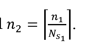
  • the XOR of the FEC codewords 300 in every section 310 is calculated. This results in a number n2 of parity codewords 301 at
  • parity codewords 301 i.e., parity codewords are grouped to compose of a different first layer section 311.
  • layer sections 311 may be composed of consecutive or adjacent parity codewords from which a second layer parity codeword 302 is
  • K represents the k-th layer of one or more packet coding layers.
  • multiple layers of packet coding processes are applied. As demonstrated above, multiple layers of packet coding processes are applied. In FIG. 3, the number of layers is equal to 3. If the number of layers is equal to 1, then only parity codewords 301 at the first layer are generated. The packet coding process at a layer higher than layer 1 is similar to treating parity codewords as FEC codewords at layer 1 to generate the next layer of parity codeword(s).
  • Ni is the number of layers:
  • the use of the multi-layer packet coding provides an additional protection on parity codewords at lower layers (e.g., at layer 1).
  • the parity codewords from multiple layers, together with the FEC codewords, may be transmitted to the receiver by the transmitter.
  • the parity codewords may be transmitted standalone upon the retransmission request of MLPC HARQ process.
  • the number of elements may vary and are wholly configurable based on system implementation in any combination, and are not limited to the example illustrated in FIG. 3.
  • FIG. 4 shows a flow diagram illustrating a transmitter procedure
  • the transmitter including at least one processor, receives a transmission block from upper layer, and may generate a cyclic redundancy check (CRC) and attach the CRC to the transmission block.
  • CRC cyclic redundancy check
  • the transmitter may execute segmentation of the transmission block so that each segment is configured to a size fitting to an inner FEC encoder.
  • the transmitter may further generate a CRC for each segment and attach the CRC to each segment.
  • each data segment with CRC is then passed through the block of an outer encoder.
  • the outer code may be a Reed-Solomon code, fountain codes (or rateless erasure code), such as raptor code, Bose-Chaudhuri- Hocquenghem (BCH) code, or any other type of code.
  • the outer encoder may also be turned on and off, based on one or more various conditions.
  • the one or more various conditions may be one or any combination of HARQ statistics or data quality of service (QoS).
  • the HARQ statistics may be obtained by observing the outputs of a "legacy (inner) channel decoder". If most of the "legacy (inner) channel decoder" outputs are correct, then the outer encoder may not be needed.
  • the outer encoding block may be turned off if the source data requires less error protection but requires low latency. Otherwise, the outer encoding block could be turned on.
  • an interleaver may be used between the outer encoder and the inner encoder.
  • the transmitter may determine, based on a total length of the source data and their QoS requirements, a total number of layers Ni to apply to MLPC. Correspondingly, the transmitter may further determine the number of sections N s per layer.
  • each layer is composed of 10 sections.
  • each section may be composed of multiple FEC codewords.
  • each section corresponds to a parity (XOR) codeword of all component (i.e., previous layer) codewords.
  • XOR parity
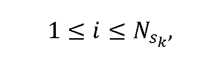
  • a total number of segments N, the number of layers (N t — 1), and the number of codewords N Sk per section for (k-l)-th layer satisfy:
  • a section of data segments is actually a group of code blocks.
  • Each code block in a section may or may not be attached with code block level CRC.
  • FIG. 5 illustrates a finite state machine for switching among different states corresponding to packet coding rates according to one or more embodiments.
  • the transmitter may be in State 0 501, which does not apply packet coding at all.
  • the transmitter may be in State 1 502 that employs high rate packet coding.
  • the transmitter may be in some state 503 (e.g., State 1) that employs lower rate packet coding.
  • the transmitter may be in the last State S 504 which employs lowest rate packet coding.
  • the switch among these states could follow Markov chain or may jump through certain rules, e.g., like the backoff window size in a binary exponential backoff algorithm.
  • Each state may correspond to certain values
  • the transmitter encodes each segment by an inner FEC encoder, e.g., Turbo, LDPC, polar codes or convolutional code (CC) which may be an LTE CC or any advanced CC.
  • an inner FEC encoder e.g., Turbo, LDPC, polar codes or convolutional code (CC) which may be an LTE CC or any advanced CC.
  • CRC may be attached to each segment before encoded by an inner FEC encoder such as turbo or polar codes.
  • CRC may not be attached as the parity-check criterion for some inner FEC encoders, such as LDPC, may be used for early stop of decoding and error check which may be used for HARQ acknowledgement generation.
  • FEC codewords are generated.
  • the transmitter sets a counter value, layer 1, to
  • the transmitter compares the value stored in the counter, layer 1 to N s i, and proceeds to operation 445 if the counter value, layer 1, is greater than N s i, and proceeds to operation 455 if the counter value, layer 1, is less than or equal to N s i.
  • the transmitter calculates the parity (XOR) of these N s FEC codewords, which can be considered as a new encoded segment at the second layer (i.e., a parity codeword). Furthermore, at each higher layer iteration, after encoding every N s . segments at layer i, the XOR of these N s . segments is calculated, which can be considered as a new encoded segment at layer i + 1.
  • the transmitter stores the generated parity codewords, and, then, increments the counter value, layer 1, in operation 450.
  • the FEC codewords and/or parity codewords are transmitted by the transmitter to the receiver after executing rate matching, modulation and other physical process.
  • the other physical process may include the resource mapping.
  • the transmitter may sort the RBs according to reliability, and apply the highest level or layer parity codewords to the least reliable RBs until the highest level of parity codewords are mapped, apply the next highest level of parity codewords to less liable RBs until this level of parity codewords are mapped, and so on until the lowest level of parity codewords are mapped to more reliable RBs or until the FEC codewords are mapped to more reliable (or the most reliable) RBs.
  • This design may ensure less retransmission rate from the beginning or the lower layer.
  • the reliabihty of RB or PRB may be indicated by channel state related measurements (such as channel state information (CSI), signal-to-interference-plus-noise ratio (SINR), or the like) corresponding to that PRB.
  • channel state related measurements such as channel state information (CSI), signal-to-interference-plus-noise ratio (SINR), or the like
  • CSI channel state information
  • SINR signal-to-interference-plus-noise ratio
  • Higher resolution CSI feedback than full-band CSI feedback may be provided to facilitate the resource allocation for MLPC, e.g., sub-band CSI feedback, or one or more RB based CSI feedback.
  • Periodic or aperiodic CSI feedback may be used to facilitate the resource allocation for MLPC.
  • FIG. 6 shows a flow diagram of a decoding procedure 600 at a receiver for MLPC layer 0 codewords according to one or more embodiments.
  • the decoding procedure 600 starts decoding the layer 0 codewords when a receiver receives some data from a transmitter at operation 605.
  • a demodulation block of the receiver provides, for example, a log- Likelihood Ratio (LLR) of the transmitted FEC codeword (e.g., one of FEC
  • a decoder e.g., inner FEC decoder such as a turbo, LDPC, polar, or convolutional decoder
  • a decoder waits for a new or updated for an FEC codeword 300 from layer 1.
  • LLR demodulation output is used for this example, it will be understood that different types of demodulation outputs other than LLR may be applied.
  • the decoder attempts to decode the FEC codeword and determines whether the decoding
  • bits Pi are saved in memory, such as a buffer memory. Also, the corresponding FEC codeword is calculated and saved in the memory.
  • operation 635 a determination is made whether all FEC codewords in a section (e.g., one of sections 310) are successfully decoded. If not all the FEC codewords in the section are successfully decoded, then operation 610 of the procedure is repeated using an updated LLR.
  • the parity codeword e.g., parity codeword 301 corresponding to the current section 310 for this section is saved in the memory, and all the FEC codewords corresponding to this parity codeword (or section) are released or cleared from the memory.
  • FIG. 7 shows a flow diagram of a decoding procedure for MLCP high layer (i.e., greater than layer 0 (i.e., >0)) codewords according to one or more embodiments. More particularly, FIG. 7 shows the decoding procedure for packet coding at layer k, where is the number of
  • a demodulation block of the receiver provides, for example, an
  • a decoder e.g., inner FEC decoder such as a turbo, LDPC, polar, or convolutional decoder
  • a decoder waits for a new or updated for a parity
  • this parity codeword is decoded, in operation 715, using the inner FEC decoder (e.g., turbo, LDPC, polar, etc.).
  • the inner FEC decoder e.g., turbo, LDPC, polar, etc.
  • source information bits P are being transmitted by a transmitter to the receiver, but first they are encoded to C as a FEC codeword by the transmitter.
  • the receiver will demodulate the LLR of C, i.e., LLR(C). Then the decoder will try to obtain P based on the LLR(C).
  • this parity codeword is not decoded successfully (i.e., if information bits are not decoded successfully) (see operation 720), then the LLR for this parity codeword is saved for later decoding and the procedure moves back to operation 710 (see operation 725).
  • the receiver will save only the FEC codeword here. Note that this parity
  • codeword at layer k>0 is generated by an XOR of several (lower layer) codewords at layer k-1.
  • a layer 2 parity codeword is derived from an XOR of layer 1 parity codewords.
  • a layer 3 parity codeword is derived from an XOR of layer 2 parity codewords.
  • These lower layer parity codewords are also referred to as composing codewords. That is, the composing codewords are those codewords from layer k- 1 used to generate the layer k parity codeword (e.g., by an XOR operation).
  • the composing codewords may be FEC codewords or lower layer parity codewords depending on layer k.
  • operation 735 if not all the composing codewords (at layer k— 1) are successfully decoded, then for each un-decoded composing codeword, the LLR is updated (see operation 750). This triggers the decoding procedures for layer k— 1, which may begin again at either operation 610 or 710 depending on layer k.
  • LLR L
  • T may be apphed such that bit '0' maps to infinite and bit '1' maps to negative infinite.
  • the function is a unity function
  • is the summation of two LLRs.
  • the updated LLR's are given by:
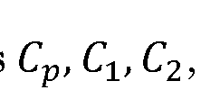
  • XOR- based LLR may be performed. Provided the parity codeword C p is the XOR of several composing codewords and given the observation of C p at the
  • the receiver may perform any one or a combination of the following operations.
  • the receiver may use C p to recover failed FEC codeword(s).
  • the receiver may use C p to update the liability of each of FEC codewords
  • each FEC codeword may be updated.
  • the receiver also may perform iterative decoding based on the procedure explained above.
  • the receiver may also use the higher layer parity codeword C p to update the liabihty of the lower layer parity codewords.
  • the receiver may update the liability (e.g., LLR, probabihty, etc.) of An algorithm may be used for the update.
  • LLR liability
  • probabihty e.g., probabihty, etc.
  • the probability of Ci may be updated.
  • the probability of C 2 may be updated by exchanging the position of C 2 and Ci in Equation (1) and Equation (2).
  • C p may be updated in a similar way because the parity check constrain may be rewritten to Equation (1) and
  • Equation (3) the above mentioned algorithm may be expended to any parity check constraints (e.g., more than two FEC codewords case).
  • the algorithm may be implemented with LLRs other than the probabilities, as described below.
  • one of the Ck may represent the parity check codeword (i.e., parity codeword or composing codeword), while the rest of Cm (m ⁇ k) may represent the FEC codeword.
  • the n th bit in each codeword may be denoted by thus:
  • the LLR of a bit may be denoted as:
  • the updated LLR of a bit is of a bit Using
  • Equation (4) may be simplified by factoring the LLR values to its sign and magnitude, which may result:
  • HARQ procedure may be used for MLPC. For example, a tier-1 inner-code HARQ procedure may be executed based on whether the inner decoding fails or succeeds, and a tier-2 outer-code HARQ procedure may be executed based on whether the outer decoding fails or succeeds.
  • multi-tier outer-code/inner-code HARQ procedure is applied for MLPC in this example, it may be used for any communication system with outer coding and inner coding with or without MLPC.
  • the outer coding/decoding may be activated/enabled and deactivated/disabled by any signaling method described herein.
  • the outer coding/decoding may also be dynamically activated/enabled and deactivated/disabled based on inner decoding result or tier- 1 inner-code HARQ acknowledgment.
  • FIG. 8 illustrates a state machine of a multi-tier outer code/inner code hybrid automatic repeat request (HARQ) according to one or more embodiments.
  • HARQ hybrid automatic repeat request
  • the receiver may remain in or be configured to state 801.
  • a tier- 1 inner-code HARQ ACK may be generated by the receiver and sent back to the transmitter, and it may be desired to disable/deactivate the outer coding/decoding for power saving and low latency.
  • the receiver may remain in or configured to state 802.
  • tier-1 inner-code HARQ NACK may be generated by the receiver and sent to the transmitter to request HAEQ retransmission, and it may be desired to enable/active outer coding/decoding for further error correction and reliable communication.
  • tier-1 inner-code HARQ retransmission may be ignored or discarded to reduce the HARQ latency and soft-combining complexity. If the outer decoding fails, tier-2 outer-code HARQ NACK may be generated by the receiver and sent to the transmitter to request HARQ retransmission.
  • the receiver may switch from state 801 to state 802 upon detecting one or more bad channel conditions (e.g., where one or more channel conditions is not satisfactory according to one or more design parameters) or upon generating or transmitting a tier-1 inner-code HARQ NACK.
  • the receiver may switch from state 802 to state 801 upon detecting one or more good channel conditions (e.g., where one or more channel conditions is satisfactory according to one or more design parameters), or when all channel conditions are satisfied, or upon generating or transmitting a tier-2 outer-code HARQ ACK.
  • multi-tier outer-code/inner- code HARQ procedure may be as follows:
  • IF ACK feedback is continuous for K times, disable out coding.
  • K may be an integer number larger than 0, which may be determined by the target block error rate (BLER), latency and/or complexity.
  • BLER target block error rate
  • the example implementation of the multi-tier outer-code/inner- code HARQ procedure may further be as follows:
  • IF inner decoding fails at the receiver: IF soft-combining is supported, preserve the failed data in memory; ELSE (IF soft-combining is not supported), discard the failed data.
  • the acknowledgements (i.e., either positive or negative) for each section of the transport block may be provided in a multi-bit acknowledgement message that includes the acknowledgements for all sections.
  • an MLPC HARQ procedure may be as follows.
  • k-t layer 0 ⁇ k ⁇ Ni— 1
  • three MLPC-layer dependent feedback states may be proposed as: ACK, NACKl k , and NACK2 k .
  • a retransmission FEC codeword or a parity codeword at layer k may be sent by one or any combination of methods proposed below.
  • a parity codeword at layer (k+ 1) may be sent by using one or any combination of the methods described below.
  • the PER THK may be the same or different for different k layers.
  • PER THI may be different from PER THK for 1 ⁇ k.
  • PER THK may be the same for 1 ⁇ k since an FEC codeword may have a different error correction performance from XOR operation based parity codeword.
  • this scheme may reduce to the coded block (CB) based HARQ retransmission and this results in the NACKl state. If all sections are in the NACKl state, then, one or more CBs or the whole associated transport block (TB) will be retransmitted.
  • CB coded block
  • NACK2 state NACK2 state.
  • the above proposed MLPC HARQ procedure may be applied.
  • CB-based HARQ retransmission may be applied.
  • PER THO 0, i.e., the NACK2 state does not exist, then 1 bit ACK/NACK per section (or group) may be used to indicate if all the code blocks within the section (or group) are decoded correctly. If it is a NACK for a section, then all the code blocks in this section will be re-transmitted. If a TB contains multiple sections, then multiple section-based (or group-based) ACK/NACK will be provided as feedback. Overall, the number of ACK/NACK bits generated for a TB is equal to the number of sections for this TB in case 1 bit ACK/NACK per section (or per group) is used.
  • NACK1, NACK2 For example, an additional state of NACK3 may be used, where the NACK3 corresponds to the condition PER' THk ⁇ PER k ⁇ PER THk and NACK2 corresponds to the condition 0 ⁇ PER k ⁇ PER' THk .
  • different PER thresholds are set by PER' THk ⁇ PER k ⁇ PER THk .
  • the transmitter When the transmitter receives NACK2 from the receiver, the transmitter may be configured to send a single parity codeword.
  • the transmitter receives NACK3 it may be configured to send more than one parity codeword.
  • the transmitter receives NACK1 it may be configured to resend all the codewords in the section (or group).
  • This simple extension uses two bits ACK/NACK per section, i.e., '00' may correspond to ACK, '01' may correspond to NACK1, '10' may correspond to NACK2, and '11' may correspond to NACK 3.
  • acknowledgements i.e., either positive or negative
  • the acknowledgements for each section of the transport block may be provided in a multi-bit acknowledgement message (e.g., a block ACK message) that includes the acknowledgements for all sections.
  • a multi-bit acknowledgement message e.g., a block ACK message
  • any one or a combination of the following methods may be used.
  • a multi -layer parity codeword is transmitted with the size equal to the number of the largest transmitted bits of all FEC codewords. Accordingly, the parity codeword may use the same coding rate as the lowest coding rate of all FEC codewords. This may also be applied to generate higher layer parity codeword from lower layer parity codewords.
  • FIG. 9 shows a diagram of a multi-layer parity codeword according to one or more embodiments.
  • zero padding (ZP) bits are added to the FEC codewords C2 to C(K-1) prior to generating the multilayer parity codeword at C(K) such that all codewords C0-C(K-1) have the same number of bits.
  • a multi -layer parity codeword is transmitted with a size smaller than the FEC codewords.
  • FIG. 10 shows a diagram of another multi-layer parity codeword according to this embodiment.
  • the parity codeword may use the higher coding rate than FEC codewords. This may also be applied to generate higher layer parity codeword from lower layer parity codewords.
  • 'x' is a number of parity to be computed and transmitted in a localized fashion, the 'x' number of parity bits may be computed from the beginning of the transmitted FEC codeword bits.
  • the 'x' may be size of smallest number in case of different transmitted bits.
  • the 'x' may also be a smaller number dependent on the code-rate currently being used.
  • a small x may be used for a high-code-rate and a high code-rate may be used in a high-SNR channel thereby sending a fewer number of multi-later parity bits in order to reduce overhead.
  • a high value of 'x' may be used in low SNR channels thereby generating and transmitting a large number of parity bits.
  • FIG. 11 shows a diagram of a another multi-layer parity codeword according to one or more embodiments.
  • [0166] This may be done by using patterned selection.
  • An example of such a pattern may be [1, 0], which may be applied and illustrated by selecting bits as [1,3,5,7 .... ].
  • the pattern may be [1 1 1 0], which may be applied and illustrated by selecting bits as [1,2,3, 5,6,7 9, 10, 11, 13 ... ].
  • Other examples for such a pattern include, but are not limited to, parity [1, 1, 1, 0, 0, 1] and parity [1, 1, 1, 0, 0, 1, 1, 0, 0, 1]. It may also be possible to first interleave the codewords identically and then select first x bits for the parity. This also generates a pseudo random pattern for pruned parity.
  • ZP zero padding
  • any one or a combination of the following methods may be used.
  • RV redundancy versions
  • RLC radio link control
  • the failed FEC codeword(s) and the first layer parity which is associated the failed FEC codeword(s) are retransmitted.
  • different bits of FEC codeword and corresponding part of parities may be sent.
  • Different FEC codeword bits and parity bits may be sent. Both may be selected independently as a function of the RV number. The selection of these bits may be done with predefined pattern or interleaver followed by truncation as described in previous paragraph. Alternatively, all the lower layer parities may be sent and a different part of FEC codeword is sent as a function of the RV number.
  • retransmitted multi-layer parities are used to reconstruct the lower layer parity codeword, and hence to recover FEC codeword(s).
  • the multi-layer parities may span different sessions. Further, the parities may be only combined if the parities were generated using identical codewords.
  • HARQ transmission for MLPC may use one or any combination of the following methods.
  • HARQ codeword bits
  • Adaptive HARQ or non-adaptive HARQ may be used for the transmission.
  • Non-adaptive HARQ with the same modulation and coding scheme (MCS) and/or the same resource which may denote the resource in one or any combination of time, frequency, spatial and/or code (or signal) domains.
  • MCS modulation and coding scheme
  • Adaptive HARQ may use different MCS for different retransmission over the same resource, or the same MCS over different resource, or different MCS over different resource.
  • any one or a combination of the following methods may be used: chase combining for small buffer size; if different retransmissions use different RV, IR combining may perform better at the cost of buffer size; parities may be only combined if they were generated with same codewords; new parities may be used to reconstruct a newly received codeword only and may not be combined; and HARQ combining may use one or any combination of the combining methods described above.
  • Parity codewords are specific to the codewords used to generate it. Hence, they may be only combined if they were generated with the same codewords.
  • any one or a combination of the following information may be signaled: number of layers of parity codewords used; the section ID to which the multi-layer parity codeword corresponds; and the resource ID on which the data is transmitted. Additionally, if it is piggy backed over a shared channel with new information bits and new HARQ process, the receiver may also need the bit-offset and number of bits used for these multi-layer parity codewords (i.e., the retransmitted parity codewords), where this may be indicated explicitly for each layer individually. Alternatively, the bit-offset and a total number of parity bits are indicated explicitly for all layers. Information for each layer may be computed implicitly.
  • the information may be part of downlink control information (DCI) / uplink control information (UCI), and this DCI / UCI may be transmitted as part of uplink or downlink control channel or shared channel.
  • DCI downlink control information
  • UCI uplink control information
  • FIG. 12 shows a diagram of a call flow for activating and deactivating the outer coding according to this embodiment. For example, suppose two terminals communicate to each other and, initially, the outer coding is not activated, and only inner coding is applied. If terminal 2 (e.g., a receiver) finds that the inner codes do not achieve good decoding performance according to meeting a desired performance parameter, terminal 2 may decide to activate its outer coder (1205) send a request 1210 to terminal 1 (e.g., the transmitter) to activate the outer coding.
  • terminal 1 e.g., the transmitter
  • Terminal 1 may accept/deny the request (1215) to activate its own outer coder by sending back a response 1220.
  • Terminal 2 may further acknowledge the reception of this response by sending an ACK 1230. Then, both terminals 1 and 2 may synch up to activate the outer coding.
  • the decision to activate the outer coding may be due to the high blocker error rates (after HARQ). It may also depend on the data QoS requirement. For example, for data with relaxed latency requirements, the outer coding could be activated.
  • the starting time for activating outer coding can be obtained either in the initial request message or in the subsequent responding message.
  • a terminal may send a request to the other terminal to deactivate the outer coding.
  • the other terminal may accept/deny the request by sending response back.
  • the first terminal could acknowledge the reception of this response.
  • both terminals may synch up to deactivate the outer coding.
  • the decision to deactivate the outer coding may be due to the low blocker error rates (after HAEQ). It may also depend on the data QoS requirement. For example, for data with tight latency requirements, the outer coding could be deactivated.
  • the starting time for deactivating outer coding can be obtained either in the initial request message or in the subsequent responding message.
  • a channel coding selection scheme for a data channel is further disclosed.
  • the channel coding is pre-defined in the 3GPP specification. For example, usage of a channel coding scheme and coding rate for transport channels (TrCHs) (e.g., UL-SCH, DL-SCH, paging channel (PCH), multicast channel (MCH) and broadcast channel (BCH) for LTE systems is shown in Table 1. It is seen from Table 1 that both UL-SCH and DL-SCH are based on the same coding scheme: turbo coding. In other words, the UL and DL data channel are using identical channel codes.
  • TrCHs transport channels
  • PCH paging channel
  • MCH multicast channel
  • BCH broadcast channel
  • the DL and UL coding schemes may be de-coupled.
  • the de-coupling of DL and UL coding schemes e.g., LDPC coding, turbo coding, polar coding, and convolutional coding
  • a DL coding scheme may be selected based on the decoding complexity, while UL coding scheme can be selected based on the decoding performance, as the decoding complexity may of less concern to the eNodeB. For example, having good decoding performance may be important in the UL because it results in enhanced link budget or it may have less power consumption at the WTRU.
  • the channel coding may be selected based on one or any combination of the following criteria.
  • different channel coding schemes and/or coding rate may be selected for a WTRU in order to reduce the implementation complexity and power consumption.
  • different channel coding schemes and/or coding rates may be selected for the eNodeB in order to improve the performance, reduce latency and/or increase flexibility such as variable code length, code rate, HARQ (as applicable for particular scenarios).
  • the channel coding may depend on the WTRU category and/or the combination WTRU category and UL/DL. Therefore, it is possible to specify a WTRU's capability in terms of its supported coding schemes and coding rates.
  • This specification can be contained in WTRU capability information element (IE), which may be implicitly indicated by WTRU category. For example, a new field may be included in a WTRU's capabihty IE to indicate the coding schemes/rates for UL and/or DL.
  • IE WTRU capability information element
  • an eNodeB may select coding schemes/rates for UL and/or DL and send configuration information regarding the selected coding schemes/rates to the WTRU which implements the set configuration.
  • the selection may also be adapted dynamically by the eNodeB based on current UL and/or DL channel conditions.
  • Category XI may support DL convolutional coding with coding rates 1/6 and 1/3. This may be due to the low decoding complexity and power consumption. While for UL, it supports LDPC coding with coding rate 1/3 and 1/2 due to its high decoding performance: low decoding latency due to parallel processing, high reliabihty due to the lack of error floor.
  • Category X2 may support DL convolutional coding with coding rates 1/6 and 1/3, due to its low decoding complexity and power consumption. While for UL, it supports polar coding with coding rates 1/3, 1/2, 5/6, 8/9. This may be due to the flexibility rates of polar code, and its high performance at higher coding rates.
  • Category X3 may support DL polar coding with coding rates 1/12 and 1/3. This is because the decoding speed is not an important factor for the application scenario. It could support turbo coding with coding rates 1/3 for UL. This may be due to the relaxation of the highly reliability, as turbo codes are known for some error floor.
  • the channel coding selection scheme may depend on block size and/or the combination of block size with WTRU category and/or UL/DL. Besides the UL and DL, the channel coding schemes may also depend on the block size. In an example, a larger block size normally corresponds to higher code rates and higher data rates. Block size is related to MCS levels.
  • LDPC codes Based on current channel codes, LDPC codes have good performance at high coding rates and large block sizes. Due to the parallel decoding nature, LDPC codes have low implementation complexity and low decoding latency, implying high throughput. On the other hand, polar codes have shown good performance at small block sizes and low coding rates, while turbo codes have proven their advantages in the flexibility (especially in HARQ) and stable performance.
  • MCS level may be introduced in the channel codes partition criteria.
  • LDPC codes may be used for large block size and polar codes may be used for small block size in response to their respective performance region.
  • the implementation complexity of polar codes may not be an issue when it is used for small block size.
  • LDPC codes are used for large block size and turbo codes are used for small block size due to its stable performance.
  • the block size may be used for channel codes partition criteria. For example, for certain WTRU categories where high throughput is an important consideration, LDPC code may be used for large block size for both UL and DL due to its high throughput and good performance. Also, polar code may be used for small block size for DL due to its good performance, while turbo codes may be used for small block size for UL due to its proven flexibility and stable performance. For another WTRU category where the energy efficiency is the main design criteria, LDPC code may be used for DL due to its low implementation complexity and polar code may be used for UL due to its good performance and enhanced link budget.
  • LDPC code may be used for DL due to its fast decoding algorithm, while turbo code can be used for UL due to its stable performance.
  • Table 3 shows some example channel coding schemes separated by WTRU category, UL/DL and block length.
  • the selection of channel codes for different use cases may be different or the same. Different use cases may be associated with a different set of WTRU categories. The above channel code selection scheme based on WTRU category may be applied to different use cases accordingly.
  • a channel coding selection scheme for a control channel is provided such that above schemes describing channel coding for a data channel may be also applied to control channel.
  • Table 4 shows the channel coding schemes and coding rates used for an LTE control channel for transmitting control information (e.g., DCI, control format indicator (CFI), HARQ indicator (HI), UCI, sidelink control information (SCI), etc.).
  • control information e.g., DCI, control format indicator (CFI), HARQ indicator (HI), UCI, sidelink control information (SCI), etc.
  • different codes e.g., tail-biting convolutional codes (TBCC), Reed-Muller codes, and Repetition codes
  • TBCC tail-biting convolutional codes
  • Reed-Muller codes e.g., Reed-Muller codes, and Repetition codes
  • Polar codes have shown good performance at very small block length and low coding rates. Polar codes may be used as a unified channel code for control information or a control channel. Or, polar codes could be used together with some other channel codes (e.g., repetition code) for a control channel so as to reduce the total number of channel codes for a control channel. For example, polar codes could be applied to DCI, CFI, UCI, and SCI, as well as other new types control information for NR, while HI may be based on repetition codes.
  • An example usage of channel coding scheme and coding rate for control information is provided in Table 5. Another example usage of channel coding scheme and coding rate for control information is provided in Table 6.
  • Examples of computer-readable storage media include, but are not limited to, a read only memory (ROM), a random access memory (RAM), a register, cache memory, semiconductor memory devices, magnetic media such as internal hard disks and removable disks, magneto-optical media, and optical media such as CD-ROM disks, and digital versatile disks (DVDs).
  • ROM read only memory
  • RAM random access memory
  • register cache memory
  • semiconductor memory devices magnetic media such as internal hard disks and removable disks, magneto-optical media, and optical media such as CD-ROM disks, and digital versatile disks (DVDs).
  • a processor in association with software may be used to implement a radio frequency transceiver for use in a WTRU, UE, terminal, base station, RNC, or any host computer.

Landscapes

  • Engineering & Computer Science (AREA)
  • Signal Processing (AREA)
  • Computer Networks & Wireless Communication (AREA)
  • Physics & Mathematics (AREA)
  • Probability & Statistics with Applications (AREA)
  • Theoretical Computer Science (AREA)
  • Mobile Radio Communication Systems (AREA)
  • Error Detection And Correction (AREA)
  • Detection And Prevention Of Errors In Transmission (AREA)

Abstract

Communication devices, systems and methods for performing multi-layer packet coding (MLPC) in a wireless system are provided. The MLPC includes segmenting a data stream into a plurality of data segments, encoding each of the plurality of data segments into a plurality of forward error correction (FEC) codewords, performing a first exclusive OR (XOR) operation on the plurality of FEC codewords to generate a plurality of first layer parity codewords, performing a second XOR operation on the plurality of first layer parity codewords to generate at least one second layer parity codeword, and transmitting at least one of: the plurality of FEC codewords, the plurality of first layer parity codewords, or the at least one second layer parity codeword.

Description

MULTI-STAGE FORWARD ERROR CORRECTION WITH PARITY CODES
CROSS REFERENCE TO RELATED APPLICATIONS
[0001] This application claims the benefit of U.S. Provisional
Application No. 62/334,762 which was filed on May 11, U.S. Provisional Application No. 62/400,721 which was filed on September 28, 2016 and U.S. Provisional Application No. 62/416,303 which was filed on November 2, 2016, the contents of which is hereby incorporated by reference herein.
BACKGROUND
[0001] The throughput of wireless communication systems has increased with the use of the new technologies introduced in LTE and Wi-Fi. These technologies, however, are not sufficient to meet the demands of future applications which will have multiple requirements. For example, future applications may demand any one or a combination of the following: high throughput in a few Gbits/sec, low latency in less than 1 ms, and high reliability in less than 10 5 packet error rate (PER).
[0002] Research on a new radio access technology, known as 5G, has started. As the applications and ubiquity of cellular communication systems grow, the applications and cellular communication systems are expected to support new features, and meet a more stringent set of performance requirements.
SUMMARY
[0003] Communication devices, systems and methods for performing multi-layer packet coding (MLPC) in a wireless system are provided.
[0004] In an example, the MLPC includes segmenting a data stream into a plurality of data segments, encoding each of the plurality of data segments into a plurality of forward error correction (FEC) codewords, performing a first exclusive OR (XOR) operation on the plurality of FEC codewords to generate a plurality of first layer parity codewords, performing a second XOR operation on the plurality of first layer parity codewords to generate at least one second layer parity codeword, and transmitting at least one of: the plurality of FEC codewords, the plurality of first layer parity codewords, or the at least one second layer parity codeword.
[0005] In another example, the MLPC includes segmenting data in a transport block into a plurality of data segments over a plurality of sections, encoding each of the plurality of data segments into a plurality of forward error correction (FEC) codewords, transmitting FEC codewords of the plurality of FEC codewords for each of the plurality of sections of the transport block, receiving a plurality of feedback bits, each feedback bit indicating an acknowledgement (ACK) or a negative acknowledgement (NACK) for a different one of the a plurality of sections of the transport block. A feedback bit indicates the NACK in response to at least one failed FEC codeword of the transmitted FEC codewords in a corresponding section of the transport block, and the feedback bit indicates the ACK in response to successful transmission of all transmitted FEC codewords in the corresponding section of the transport block. The MLPC may further include retransmitting all the FEC codewords in the corresponding section responsive to the NACK.
BRIEF DESCRIPTION OF THE DRAWINGS
[0006] A more detailed understanding may be had from the following description, given by way of example in conjunction with the accompanying drawings wherein:
[0007] FIG. 1A is a system diagram of an example communications system in which one or more disclosed embodiments may be implemented;
[0008] FIG. IB is a system diagram of an example wireless transmit/receive unit (WTRU) that may be used within the communications system illustrated in FIG. 1A;
[0009] FIG. 1C is a system diagram of an example radio access network and an example core network that may be used within the communications system illustrated in FIG. 1A; [0010] FIG. 2 is a block diagram of a communication system utilizing outer and inner coding by serial concatenation according to one or more embodiments;
[0011] FIG. 3 shows a diagram of an example multi-layer packet coding
(MLPC) construction architecture according to one or more embodiments;
[0012] FIG. 4 shows a flow diagram illustrating a transmitter procedure for performing multiple-layer packet coding (MLPC) according to one or more embodiments;
[0013] FIG. 5 illustrates a finite state machine for switching among different states corresponding to packet coding rates according to one or more embodiments;
[0014] FIG. 6 shows a flow diagram of a decoding procedure for MLPC layer 0 codewords according to one or more embodiments;
[0015] FIG. 7 shows a flow diagram of a decoding procedure for MLCP high (>0) layer codewords according to one or more embodiments;
[0016] FIG. 8 illustrates a state machine of a multi-tier outer code/inner code hybrid automatic repeat request (HARQ) according to one or more embodiments;
[0017] FIG. 9 shows a diagram of a multi-layer parity codeword according to one or more embodiments;
[0018] FIG. 10 shows a diagram of another multi-layer parity codeword according to one or more embodiments;
[0019] FIG. 11 shows a diagram of a another multi -layer parity codeword according to one or more embodiments; and
[0020] FIG. 12 shows a diagram of a call flow for activating and deactivating the outer coding according to one or more embodiments.
DETAILED DESCRIPTION
[0021] Based on the general requirements set out by standard committees, a broad classification of the use cases for emerging New Rado (NR) or fifth-generation (5G) systems may be depicted as follows: Enhanced Mobile Broadband (eMBB), Massive Machine Type Communications (mMTC), and Ultra Reliable and Low latency Communications (URLLC).
[0022] Different use cases may focus on different requirements such as higher data rate, higher spectrum efficiency, low power and higher energy efficiency, lower latency and higher reliability.
[0023] mMTC is one of the three use case categories for the 5G cellular standards. The mMTC use case is characterized by the desire to provide connectivity for a very large number of low cost devices. For example, target applications may include smart metering, home appliances, and remote sensors. Common to all of these applications is that the data transmissions are relatively small and infrequent. One of the requirements to make these massive deployments feasible will be the ability to use low cost devices with significantly extended battery life.
[0024] The following channel coding schemes may also be used in NR or
5G systems: low-density parity-check (LDPC) code, polar code, turbo code (LTE and/or enhanced turbo coding), or convolutional code (LTE and/or enhanced convolutional coding). The combination of these codes, as well as outer erasure codes, may also be used.
[0025] With various requirements on channel coding design, new Radio
Access Technology (RAT) channel coding schemes consider: performance, implementation complexity, latency (decoding/encoding), and flexibility (e.g., variable code length, code rate, and hybrid automatic repeat request (HARQ) for particular scenarios).
[0026] For example, consider a transmitter tasked to transmit time- sensitive data to a receiver over a very noisy channel, and the segmentations of the data are encoded by an inner channel code. Due to the noisy channel, some data segmentations may not be successfully decoded even though HARQ retransmissions are applied. The missing data segments may be covered only through some ARQ processes at a higher layer (e.g., radio link control (RLC) layer). This cross-layer recovery could be time-consuming, and may be against the data latency requirements. Hence, a packet coding scheme may be used to reduce the transmission latency and improve the overall physical layer decoding performance.
[0027] However, only a single parity codewords are generated in the current packet coding schemes. Thus, current packet coding schemes do not provide good error- detection capability if the number of data segments is large. Furthermore, the error protection of the transmission of a parity codeword is not guaranteed. Finally, the current packet coding scheme has low flexibility, in terms of its HARQ operations. Hence, it may be desirable to design advanced packet coding schemes to solve the above problems.
[0028] There may also be a problem signaling on the channel coding selection for NR. In existing LTE communication systems, the coding schemes for data channels in the uplink (UL) and downlink (DL) are kept the same. For example, the turbo codes are used in both the Downlink Shared Channel (DL-SCH) and the Uplink Shared Channel (UL-SCH), while LDPC codes are used in both directions in WiFi systems.
[0029] Due to various application scenarios, NR systems may need to take into account device hardware restrictions and mixed traffics for different use cases. For instance, an eNode-B (eNB) could have very strong computational power while an mMTC device may have limited computational power. On the other hand, the computational complexity of channel decoding is generally much more than channel encoding. Hence, the usage of the same channel coding schemes for both DL and UL may not be efficient.
[0030] FIG. 1A is a diagram of an example communications system 100 in which one or more disclosed embodiments may be implemented. The communications system 100 may be a multiple access system that provides content, such as voice, data, video, messaging, broadcast, etc., to multiple wireless users. The communications system 100 may enable multiple wireless users to access such content through the sharing of system resources, including wireless bandwidth. For example, the communications systems 100 may employ one or more channel access methods, such as code division multiple access (CDMA), time division multiple access (TDMA), frequency division multiple access (FDMA), orthogonal FDMA (OFDMA), single-carrier FDMA (SC-FDMA), and the hke.
[0031] As shown in FIG. 1A, the communications system 100 may include wireless transmit/receive units (WTRUs) 102a, 102b, 102c, 102d, a radio access network (RAN) 104, a core network 106, a pubhc switched telephone network (PSTN) 108, the Internet 110, and other networks 112, though it will be appreciated that the disclosed embodiments contemplate any number of WTRUs, base stations, networks, and/or network elements. Each of the WTRUs 102a, 102b, 102c, 102d may be any type of device configured to operate and/or communicate in a wireless environment. By way of example, the WTRUs 102a, 102b, 102c, 102d may be configured to transmit and/or receive wireless signals and may include user equipment (UE), a mobile station, a fixed or mobile subscriber unit, a pager, a cellular telephone, a personal digital assistant (PDA), a smartphone, a laptop, a netbook, a personal computer, a wireless sensor, consumer electronics, and the hke.
[0032] The communications systems 100 may also include a base station
114a and a base station 114b. Each of the base stations 114a, 114b may be any type of device configured to wirelessly interface with at least one of the WTRUs 102a, 102b, 102c, 102d to facihtate access to one or more communication networks, such as the core network 106, the Internet 110, and/or the other networks 112. By way of example, the base stations 114a, 114b may be a base transceiver station (BTS), a Node-B, an eNode B, a Home Node B, a Home eNode B, a site controller, an access point (AP), a wireless router, and the hke. While the base stations 114a, 114b are each depicted as a single element, it will be appreciated that the base stations 114a, 114b may include any number of interconnected base stations and/or network elements.
[0033] The base station 114a may be part of the RAN 104, which may also include other base stations and/or network elements (not shown), such as a base station controller (BSC), a radio network controller (RNC), relay nodes, etc. The base station 114a and/or the base station 114b may be configured to transmit and/or receive wireless signals within a particular geographic region, which may be referred to as a cell (not shown). The cell may further be divided into cell sectors. For example, the cell associated with the base station 114a may be divided into three sectors. Thus, in one embodiment, the base station 114a may include three transceivers, i.e., one for each sector of the cell. In another embodiment, the base station 114a may employ multiple-input multiple-output (MIMO) technology and, therefore, may utilize multiple transceivers for each sector of the cell.
[0034] The base stations 114a, 114b may communicate with one or more of the WTRUs 102a, 102b, 102c, 102d over an air interface 116, which may be any suitable wireless communication link (e.g., radio frequency (RF), microwave, infrared (IR), ultraviolet (UV), visible light, etc.). The air interface 116 may be established using any suitable radio access technology (RAT).
[0035] More specifically, as noted above, the communications system
100 may be a multiple access system and may employ one or more channel access schemes, such as CDMA, TDMA, FDMA, OFDMA, SC-FDMA, and the like. For example, the base station 114a in the RAN 104 and the WTRUs 102a, 102b, 102c may implement a radio technology such as Universal Mobile Telecommunications System (UMTS) Terrestrial Radio Access (UTRA), which may establish the air interface 116 using wideband CDMA (WCDMA). WCDMA may include communication protocols such as High-Speed Packet Access (HSPA) and/or Evolved HSPA (HSPA+). HSPA may include High- Speed Downhnk Packet Access (HSDPA) and/or High-Speed Uplink Packet Access (HSUPA).
[0036] In another embodiment, the base station 114a and the WTRUs
102a, 102b, 102c may implement a radio technology such as Evolved UMTS Terrestrial Radio Access (E-UTRA), which may establish the air interface 116 using Long Term Evolution (LTE) and/or LTE-Advanced (LTE-A).
[0037] In other embodiments, the base station 114a and the WTRUs
102a, 102b, 102c may implement radio technologies such as IEEE 802.16 (i.e., Worldwide Interoperability for Microwave Access (WiMAX)), CDMA2000, CDMA2000 IX, CDMA2000 EV-DO, Interim Standard 2000 (IS-2000), Interim Standard 95 (IS-95), Interim Standard 856 (IS-856), Global System for Mobile communications (GSM), Enhanced Data rates for GSM Evolution (EDGE), GSM EDGE (GERAN), and the like.
[0038] The base station 114b in FIG. 1A may be a wireless router, Home
Node B, Home eNode B, or access point, for example, and may utilize any suitable RAT for facilitating wireless connectivity in a localized area, such as a place of business, a home, a vehicle, a campus, and the like. In one embodiment, the base station 114b and the WTRUs 102c, 102d may implement a radio technology such as IEEE 802.11 to establish a wireless local area network (WLAN). In another embodiment, the base station 114b and the WTRUs 102c, 102d may implement a radio technology such as IEEE 802.15 to establish a wireless personal area network (WPAN). In yet another embodiment, the base station 114b and the WTRUs 102c, 102d may utilize a cellular-based RAT (e.g., WCDMA, CDMA2000, GSM, LTE, LTE-A, etc.) to establish a picocell or femtocell. As shown in FIG. 1A, the base station 114b may have a direct connection to the Internet 110. Thus, the base station 114b may not be required to access the Internet 110 via the core network 106.
[0039] The RAN 104 may be in communication with the core network
106, which may be any type of network configured to provide voice, data, applications, and/or voice over internet protocol (VoIP) services to one or more of the WTRUs 102a, 102b, 102c, 102d. For example, the core network 106 may provide call control, billing services, mobile location-based services, pre-paid calling, Internet connectivity, video distribution, etc., and/or perform high- level security functions, such as user authentication. Although not shown in FIG. 1A, it will be appreciated that the RAN 104 and/or the core network 106 may be in direct or indirect communication with other RANs that employ the same RAT as the RAN 104 or a different RAT. For example, in addition to being connected to the RAN 104, which may be utilizing an E-UTRA radio technology, the core network 106 may also be in communication with another RAN (not shown) employing a GSM radio technology.
[0040] The core network 106 may also serve as a gateway for the
WTRUs 102a, 102b, 102c, 102d to access the PSTN 108, the Internet 110, and/or other networks 112. The PSTN 108 may include circuit-switched telephone networks that provide plain old telephone service (POTS). The Internet 110 may include a global system of interconnected computer networks and devices that use common communication protocols, such as the transmission control protocol (TCP), user datagram protocol (UDP) and the internet protocol (IP) in the TCP/IP internet protocol suite. The networks 112 may include wired or wireless communications networks owned and/or operated by other service providers. For example, the networks 112 may include another core network connected to one or more RANs, which may employ the same RAT as the RAN 104 or a different RAT.
[0041] Some or all of the WTRUs 102a, 102b, 102c, 102d in the communications system 100 may include multi-mode capabilities, i.e., the WTRUs 102a, 102b, 102c, 102d may include multiple transceivers for communicating with different wireless networks over different wireless links. For example, the WTRU 102c shown in FIG. 1A may be configured to communicate with the base station 114a, which may employ a cellular -based radio technology, and with the base station 114b, which may employ an IEEE 802 radio technology.
[0042] FIG. IB is a system diagram of an example WTRU 102. As shown in FIG. IB, the WTRU 102 may include a processor 118, a transceiver 120, a transmit/receive element 122, a speaker/microphone 124, a keypad 126, a display /touchp ad 128, non-removable memory 130, removable memory 132, a power source 134, a global positioning system (GPS) chipset 136, and other peripherals 138. It will be appreciated that the WTRU 102 may include any sub-combination of the foregoing elements while remaining consistent with an embodiment.
[0043] The processor 118 may be a general purpose processor, a special purpose processor, a conventional processor, a digital signal processor (DSP), a plurality of microprocessors, one or more microprocessors in association with a DSP core, a controller, a microcontroller, Application Specific Integrated Circuits (ASICs), Field Programmable Gate Array (FPGAs) circuits, any other type of integrated circuit (IC), a state machine, and the like. The processor 118 may perform signal coding, data processing, power control, input/output processing, and/or any other functionality that enables the WTRU 102 to operate in a wireless environment. The processor 118 may be coupled to the transceiver 120, which may be coupled to the transmit/receive element 122. While FIG. IB depicts the processor 118 and the transceiver 120 as separate components, it will be appreciated that the processor 118 and the transceiver 120 may be integrated together in an electronic package or chip.
[0044] The transmit/receive element 122 may be configured to transmit signals to, or receive signals from, a base station (e.g., the base station 114a) over the air interface 116. For example, in one embodiment, the transmit/receive element 122 may be an antenna configured to transmit and/or receive RF signals. In another embodiment, the transmit/receive element 122 may be an emitter/detector configured to transmit and/or receive IR, UV, or visible light signals, for example. In yet another embodiment, the transmit/receive element 122 may be configured to transmit and receive both RF and light signals. It will be appreciated that the transmit/receive element 122 may be configured to transmit and/or receive any combination of wireless signals.
[0045] In addition, although the transmit/receive element 122 is depicted in FIG. IB as a single element, the WTRU 102 may include any number of transmit/receive elements 122. More specifically, the WTRU 102 may employ MIMO technology. Thus, in one embodiment, the WTRU 102 may include two or more transmit/receive elements 122 (e.g., multiple antennas) for transmitting and receiving wireless signals over the air interface 116.
[0046] The transceiver 120 may be configured to modulate the signals that are to be transmitted by the transmit/receive element 122 and to demodulate the signals that are received by the transmit/receive element 122. As noted above, the WTRU 102 may have multi-mode capabilities. Thus, the transceiver 120 may include multiple transceivers for enabling the WTRU 102 to communicate via multiple RATs, such as UTRA and IEEE 802.11, for example. [0047] The processor 118 of the WTRU 102 may be coupled to, and may receive user input data from, the speaker/microphone 124, the keypad 126, and/or the display /touchp ad 128 (e.g., a liquid crystal display (LCD) display unit or organic hght-emitting diode (OLED) display unit). The processor 118 may also output user data to the speaker/microphone 124, the keypad 126, and/or the display /touchp ad 128. In addition, the processor 118 may access information from, and store data in, any type of suitable memory, such as the non-removable memory 130 and/or the removable memory 132. The nonremovable memory 130 may include random-access memory (RAM), read-only memory (ROM), a hard disk, or any other type of memory storage device. The removable memory 132 may include a subscriber identity module (SIM) card, a memory stick, a secure digital (SD) memory card, and the like. In other embodiments, the processor 118 may access information from, and store data in, memory that is not physically located on the WTRU 102, such as on a server or a home computer (not shown).
[0048] The processor 118 may receive power from the power source 134, and may be configured to distribute and/or control the power to the other components in the WTRU 102. The power source 134 may be any suitable device for powering the WTRU 102. For example, the power source 134 may include one or more dry cell batteries (e.g., nickel-cadmium (NiCd), nickel-zinc (NiZn), nickel metal hydride (NiMH), lithium-ion (Li-ion), etc.), solar cells, fuel cells, and the like.
[0049] The processor 118 may also be coupled to the GPS chipset 136, which may be configured to provide location information (e.g., longitude and latitude) regarding the current location of the WTRU 102. In addition to, or in lieu of, the information from the GPS chipset 136, the WTRU 102 may receive location information over the air interface 116 from a base station (e.g., base stations 114a, 114b) and/or determine its location based on the timing of the signals being received from two or more nearby base stations. It will be appreciated that the WTRU 102 may acquire location information by way of any suitable location- determination method while remaining consistent with an embodiment. [0050] The processor 118 may further be coupled to other peripherals
138, which may include one or more software and/or hardware modules that provide additional features, functionality and/or wired or wireless connectivity. For example, the peripherals 138 may include an accelerometer, an e-compass, a satellite transceiver, a digital camera (for photographs or video), a universal serial bus (USB) port, a vibration device, a television transceiver, a hands free headset, a Bluetooth® module, a frequency modulated (FM) radio unit, a digital music player, a media player, a video game player module, an Internet browser, and the like.
[0051] FIG. 1C is a system diagram of the RAN 104 and the core network 106 according to an embodiment. As noted above, the RAN 104 may employ an E-UTRA radio technology to communicate with the WTRUs 102a, 102b, 102c over the air interface 116. The RAN 104 may also be in communication with the core network 106.
[0052] The RAN 104 may include eNode-Bs 140a, 140b, 140c, though it will be appreciated that the RAN 104 may include any number of eNode-Bs while remaining consistent with an embodiment. The eNode-Bs 140a, 140b, 140c may each include one or more transceivers for communicating with the WTRUs 102a, 102b, 102c over the air interface 116. In one embodiment, the eNode-Bs 140a, 140b, 140c may implement MIMO technology. Thus, the eNode-B 140a, for example, may use multiple antennas to transmit wireless signals to, and receive wireless signals from, the WTRU 102a.
[0053] Each of the eNode-Bs 140a, 140b, 140c may be associated with a particular cell (not shown) and may be configured to handle radio resource management decisions, handover decisions, scheduling of users in the uplink and/or downlink, and the like. As shown in FIG. 1C, the eNode-Bs 140a, 140b, 140c may communicate with one another over an X2 interface.
[0054] The core network 106 shown in FIG. 1C may include a mobility management entity gateway (MME) 142, a serving gateway 144, and a packet data network (PDN) gateway 146. While each of the foregoing elements are depicted as part of the core network 106, it will be appreciated that any one of these elements may be owned and/or operated by an entity other than the core network operator.
[0055] The MME 142 may be connected to each of the eNode-Bs 140a,
140b, 140c in the RAN 104 via an Si interface and may serve as a control node. For example, the MME 142 may be responsible for authenticating users of the WTRUs 102a, 102b, 102c, bearer activation/deactivation, selecting a particular serving gateway during an initial attach of the WTRUs 102a, 102b, 102c, and the like. The MME 142 may also provide a control plane function for switching between the RAN 104 and other RANs (not shown) that employ other radio technologies, such as GSM or WCDMA.
[0056] The serving gateway 144 may be connected to each of the eNode
Bs 140a, 140b, 140c in the RAN 104 via the Si interface. The serving gateway 144 may generally route and forward user data packets to/from the WTRUs 102a, 102b, 102c. The serving gateway 144 may also perform other functions, such as anchoring user planes during inter-eNode B handovers, triggering paging when downlink data is available for the WTRUs 102a, 102b, 102c, managing and storing contexts of the WTRUs 102a, 102b, 102c, and the like.
[0057] The serving gateway 144 may also be connected to the PDN gateway 146, which may provide the WTRUs 102a, 102b, 102c with access to packet-switched networks, such as the Internet 110, to facilitate communications between the WTRUs 102a, 102b, 102c and IP-enabled devices.
[0058] The core network 106 may facilitate communications with other networks. For example, the core network 106 may provide the WTRUs 102a, 102b, 102c with access to circuit-switched networks, such as the PSTN 108, to facilitate communications between the WTRUs 102a, 102b, 102c and traditional land-line communications devices. For example, the core network 106 may include, or may communicate with, an IP gateway (e.g., an IP multimedia subsystem (IMS) server) that serves as an interface between the core network 106 and the PSTN 108. In addition, the core network 106 may provide the WTRUs 102a, 102b, 102c with access to the networks 112, which may include other wired or wireless networks that are owned and/or operated by other service providers.
[0059] Other network 112 may further be connected to an IEEE 802.11 based wireless local area network (WLAN) 160. The WLAN 160 may include an access router 165. The access router may contain gateway functionality. The access router 165 may be in communication with a plurality of access points (APs) 170a, 170b. The communication between access router 165 and APs 170a, 170b may be via wired Ethernet (IEEE 802.3 standards), or any type of wireless communication protocol. AP 170a is in wireless communication over an air interface with WTRU 102 d.
[0060] Forward error correction (FEC) is a digital signal processing technique used to enhance data reliability. It does this by introducing redundant data, called error correcting code (e.g., error control bits), prior to data transmission or storage. For example, consider a message having four data bits which is to be transmitted as a 7-bit codeword by adding three error control bits. This would be called a (7, 4) code. That means that the total codeword length is seven bits, but only four of those bits are actually data.
[0061] Thus, FEC codewords are generated from the original message using an algorithm that introduces a certain amount of redundancy into the codeword; and, thus, the FEC codeword is longer than the original message. For example, an input message composed of K symbols may be input to a channel encoder that outputs an FEC codeword composed of N symbols, where N>K. Since N > K, there is redundancy in the output. This redundancy is distributed across the FEC codeword and allows the original message to be recovered with good probability even in the presence of errors. The more redundant the FEC codeword, the more resilient it is against errors, and the fewer queries required to recover a bit of the original message.
[0062] FEC provides the receiver with the ability to correct errors without a reverse channel to request the retransmission of data. Forward error coding is also known as channel coding.
[0063] Thus, channel coding is a technique commonly used in communication systems to improve the performance through the introduction of redundancy into the transmission. Various channel coding techniques have been developed and different techniques are used based on the specific application. Channel codes can be classified into block codes, where the redundancy is added to blocks of data, and convolutional codes, where the redundancy is added in a continuous fashion.
[0064] Concatenated coding attempts to combine the performance improvement of two or more FEC codes, physically layered as an inner and an outer code. For example, concatenated codes may be comprised of a stronger inner code and a weaker outer code, with an interleaver connecting the inner and outer codes together. Concatenation of codes can be serial, parallel, or multilevel code concatenation.
[0065] FIG. 2 provides an illustration of a block diagram of a communication system 200 utilizing outer and inner coding by serial concatenation according to one or more embodiments. The communication system 200 includes a transmitter 201 and a receiver 202 that communicate over a channel 203. The transmitter 201 includes an outer encoder 211, an interleaver 212 and an inner encoder 213 for generating and transmitting the data packet. Similarly, the receiver 202 includes an inner decoder 221, a de- interleaver 222 and an outer decoder 223 for receiving and decoding the encoded packet.
[0066] The transmitter 201 may be either one of an eNode-B or a
WTRU, for example, with a transceiver chipset for encoding data to be transmitted in a signal. Additionally, the receiver 202 may be either one of an eNode-B or a WTRU, for example, with a transceiver chipset for decoding data received in a signal. Thus, the transmitter 201 and the receiver 202 may refer to an entity, such as a communication device, that includes transmitter, receiver and/or transceiver components and one or more processors, and generally refers to the entity that is performing the transmitting or receiving in a transmission operation.
[0067] At the transmitter, the outer encoder 211 encodes the data with an outer code to generate an outer frame. The outer frame is then interleaved by the interleaver 212 to produce an intermediate frame. The intermediate frame is then encoded by the inner encoder 213, which encodes the intermediate frame with an inner code to generate a final frame. The data, once encoded, is transmitted across a channel 203 (i.e., a data path) and decoded at the receiver 202 in reverse order.
[0068] In particular, at the receiver 202, the inner coder 221 decodes the data at the receiver 202; then the outer coder 223 decodes the same data after it is de-interleaved by the de-interleaver 222. Employing such iterative decoding allows the outer decoder 223 to correct any remaining errors not corrected by the inner decoder 221.
[0069] The inner code may be any type of regular FEC codes. The outer code attempts to provide additional improvement of performance. The interleaver 212 rearranges the order of transmitted symbols, while the corresponding de-interleaver 222 at the receiver side restores the original order. De-interleaving may disperse a burst of errors associated with an inner- decoder error event so that these individual errors may be more easily corrected by the outer code's decoder. Thus, de -interleaving allows the inner channel-code output to appear independent from symbol to symbol.
[0070] Serial concatenation with interleaving traditionally uses an inner code that makes hard decisions on its inner-code decoder output. Such hard decisions allow the inner code-and-channel to be modeled by a binary symmetric channel (BSC) or, more generally, discrete memoryless channel (DMC). The outer code is designed to reduce probability of errors to negligible levels. Such low error probabilities essentially mean that the transmission layer is effectively error-free, a highly desirable result in many applications. This form of serial concatenation allows one of the basic results to be achieved (e.g., arbitrarily reliable transmission).
[0071] According to one or more embodiments, packet coding may be used to reduce the decoding complexity and decrease the latency. It may be used in the physical layer to allow simple XOR relationship established among independent FEC codewords to enhance the packet error rate (PER) performance. In packet coding, a single parity codeword is used for all FEC codewords via XOR operations. For example, suppose a long transport block is partitioned into several segments P1,..., Pn1. Each segment P1,..., Pn1 is encoded by a FEC channel code to generate an FEC codeword. A parity codeword is generated by applying an XOR operation to the FEC codewords resulting from all the segments P1,..., Pn1. By using packing coding, the transmission efficiency and decoding performance may be increased.
[0072] Multi-Layer Packet Coding (MLPC) may be introduced to provide reliable communication with low latency and low complexity. For example, FIG. 3 shows a diagram of an example multi-layer packet coding (MLPC) construction architecture according to one or more embodiments.
[0073] FIG. 3 illustrates k-layers of generated FEC and parity codewords. Here, denotes the i-th codeword at the k-th layer of one or
Figure imgf000019_0002
more packet coding layers. In the example illustrated in FIG. 3, there are three packet coding layers (i.e., layers 1-3), referred to as the first, second and third layers, respectively, where k=3. The zero-th layer is not counted in the total number of packet coding layers. In addition, the codewords for the zero- th layer are FEC codewords 300 which are generated from original data segments P1,..., Pn1or code blocks (CBs). The codewords 301, 302 and 303 for a higher layer (e.g., layers 1-3) are parity codewords 301, 302 and 303
Figure imgf000019_0003
which are generated by XOR operation.
[0074] Thus, provided the initial data can be partitioned to multiple segments P1 } PUi , each segment is separately processed by the inner FEC channel encoder (e.g., inner encoder 213). Hereinafter, "segment" and "code block" may be used interchangeably. The outputs
Figure imgf000019_0001
1 < i≤n1 of the inner FEC channel encoder are the FEC codewords 300, wherein ni is the number of FEC codewords 300. By MLPC, every NSiFEC codewords compose a different zero-th layer section 310. The XOR of the FEC codewords 300 in every section 310 is calculated. This results in a number n2 of parity codewords 301 at
Figure imgf000019_0006
layer 1, where 1≤ i≤n2 and
Figure imgf000019_0004
[0075] Next, every number of parity codewords 301 (i.e., parity codewords are grouped to compose of a different first layer section 311. The
Figure imgf000019_0005
XOR of the parity codewords 301 in each section 311 is calculated to generate second layer parity codewords 302. This results in a number parity
Figure imgf000020_0003
codewords 302, where For example, one of the first
Figure imgf000020_0002
layer sections 311 may be composed of consecutive or adjacent parity codewords from which a second layer parity codeword 302 is
Figure imgf000020_0004
generated therefrom by an XOR operation.
[0076] Then, every packet codewords 302 (i.e., parity codewords Cf)
Figure imgf000020_0005
are grouped to compose of a different second layer section 312. Here, only one second layer section 312 is formed. The XOR of the parity codewords 302 in each section 312 is calculated to generate third layer parity codewords 303. This result a number n4 of parity codewords 303, where 1 < i≤
Figure imgf000020_0006
This process is continued on a layer-by-layer basis until
Figure imgf000020_0001
Figure imgf000020_0009
where K represents the k-th layer of one or more packet coding layers.
[0077] As demonstrated above, multiple layers of packet coding processes are applied. As demonstrated above, multiple layers of packet coding processes are applied. In FIG. 3, the number of layers is equal to 3. If the number of layers is equal to 1, then only parity codewords 301 at the first layer are generated. The packet coding process at a layer higher than layer 1 is similar to treating parity codewords as FEC codewords at layer 1 to generate the next layer of parity codeword(s).
[0078] Thus, in a first layer operation, every FEC codewords 300
Figure imgf000020_0012
result in a parity codeword 301, Cf . In the k-t layer operation
Figure imgf000020_0015
every NSk parity codewords 301, 302, etc., from the layer where:
Figure imgf000020_0011
Figure imgf000020_0013
Figure imgf000020_0010
result in a next layer parity codeword
Figure imgf000020_0007
In general,
where Ni is the number of layers:
Figure imgf000020_0014
Figure imgf000020_0008
[0079] The use of the multi-layer packet coding provides an additional protection on parity codewords at lower layers (e.g., at layer 1). The parity codewords from multiple layers, together with the FEC codewords, may be transmitted to the receiver by the transmitter. Optionally, the parity codewords may be transmitted standalone upon the retransmission request of MLPC HARQ process.
[0080] In will be appreciated that the number of elements, including number of data segments, sections, elements within a section, FEC codewords, parity codewords, layers, and the like, may vary and are wholly configurable based on system implementation in any combination, and are not limited to the example illustrated in FIG. 3.
[0081] FIG. 4 shows a flow diagram illustrating a transmitter procedure
400 for performing MLPC according to one or more embodiments.
[0082] In operation 405, the transmitter, including at least one processor, receives a transmission block from upper layer, and may generate a cyclic redundancy check (CRC) and attach the CRC to the transmission block.
[0083] In operation 410, the transmitter may execute segmentation of the transmission block so that each segment is configured to a size fitting to an inner FEC encoder.
[0084] In operation 415, the transmitter may further generate a CRC for each segment and attach the CRC to each segment.
[0085] In operation 420, the transmitter, each data segment with CRC is then passed through the block of an outer encoder. It is noted that the outer encoder is optional. The outer code may be a Reed-Solomon code, fountain codes (or rateless erasure code), such as raptor code, Bose-Chaudhuri- Hocquenghem (BCH) code, or any other type of code. The outer encoder may also be turned on and off, based on one or more various conditions. The one or more various conditions may be one or any combination of HARQ statistics or data quality of service (QoS).
[0086] The HARQ statistics may be obtained by observing the outputs of a "legacy (inner) channel decoder". If most of the "legacy (inner) channel decoder" outputs are correct, then the outer encoder may not be needed.
[0087] With respect to the data QoS, the outer encoding block may be turned off if the source data requires less error protection but requires low latency. Otherwise, the outer encoding block could be turned on. [0088] Optionally, if the outer encoding block is enabled, an interleaver may be used between the outer encoder and the inner encoder.
[0089] In operation 425, the transmitter may determine, based on a total length of the source data and their QoS requirements, a total number of layers Ni to apply to MLPC. Correspondingly, the transmitter may further determine the number of sections Ns per layer.
[0090] For example, in a case including source date of 100 segments, there may be 2 layers and each layer is composed of 10 sections. For the zero- th layer, each section may be composed of multiple FEC codewords. For the first (or higher) layer, each section corresponds to a parity (XOR) codeword of all component (i.e., previous layer) codewords. In general, a total number of segments N, the number of layers (Nt— 1), and the number of codewords NSk per section for (k-l)-th layer, satisfy:
Figure imgf000022_0001
In a simple case that It is noted
Figure imgf000022_0002
that the generation of the sections or groups for the zero-th layer is equivalent before and after inner channel coding. For the zero-th layer, a section of data segments is actually a group of code blocks. Each code block in a section may or may not be attached with code block level CRC.
[0091] FIG. 5 illustrates a finite state machine for switching among different states corresponding to packet coding rates according to one or more embodiments. Depending on the channel and interference conditions, there may be multiple packet coding states. In good channel and interference conditions, the transmitter may be in State 0 501, which does not apply packet coding at all. In a relatively bad channel and interference conditions, the transmitter may be in State 1 502 that employs high rate packet coding. In a still worse channel and interference conditions, the transmitter may be in some state 503 (e.g., State 1) that employs lower rate packet coding. In the worst channel and interference conditions, the transmitter may be in the last State S 504 which employs lowest rate packet coding. The switch among these states could follow Markov chain or may jump through certain rules, e.g., like the backoff window size in a binary exponential backoff algorithm. Each state may correspond to certain values
Figure imgf000023_0001
[0092] Returning to FIG. 4, in operation 430, the transmitter encodes each segment by an inner FEC encoder, e.g., Turbo, LDPC, polar codes or convolutional code (CC) which may be an LTE CC or any advanced CC. To provide early stop of decoding and error check, CRC may be attached to each segment before encoded by an inner FEC encoder such as turbo or polar codes. Optionally, CRC may not be attached as the parity-check criterion for some inner FEC encoders, such as LDPC, may be used for early stop of decoding and error check which may be used for HARQ acknowledgement generation. Thus, FEC codewords are generated.
[0093] In operation 435, the transmitter sets a counter value, layer 1, to
1.
[0094] In operation 440, the transmitter compares the value stored in the counter, layer 1 to Nsi, and proceeds to operation 445 if the counter value, layer 1, is greater than Nsi, and proceeds to operation 455 if the counter value, layer 1, is less than or equal to Nsi.
[0095] In operation 445, after encoding every Ns segment into an FEC codeword, the transmitter calculates the parity (XOR) of these Ns FEC codewords, which can be considered as a new encoded segment at the second layer (i.e., a parity codeword). Furthermore, at each higher layer iteration, after encoding every Ns. segments at layer i, the XOR of these Ns. segments is calculated, which can be considered as a new encoded segment at layer i + 1. The transmitter stores the generated parity codewords, and, then, increments the counter value, layer 1, in operation 450.
[0096] In operation 455, the FEC codewords and/or parity codewords are transmitted by the transmitter to the receiver after executing rate matching, modulation and other physical process. The other physical process may include the resource mapping.
[0097] There are several options to map FEC codewords and parity codewords to different resource blocks (RBs) or physical resource block (PRB). One option is to map FEC codewords to more reliable RBs, i.e., the RBs with the least fading, while map parity codewords to less reliable RBs. Thus, the higher level parity codewords are mapped to less reliable RBs. For example, the transmitter may sort the RBs according to reliability, and apply the highest level or layer parity codewords to the least reliable RBs until the highest level of parity codewords are mapped, apply the next highest level of parity codewords to less liable RBs until this level of parity codewords are mapped, and so on until the lowest level of parity codewords are mapped to more reliable RBs or until the FEC codewords are mapped to more reliable (or the most reliable) RBs. This design may ensure less retransmission rate from the beginning or the lower layer.
[0098] Conversely, another option is to map FEC codewords to less reliable RBs, while map parity codewords to more reliable RBs. Thus, the higher level parity codewords are mapped to more rehable RBs. This design may ensure high error correction capabilities once some error occurs.
[0099] Other options with some mixed operations of the above mapping methods may be also possible. The reliabihty of RB or PRB may be indicated by channel state related measurements (such as channel state information (CSI), signal-to-interference-plus-noise ratio (SINR), or the like) corresponding to that PRB. Higher resolution CSI feedback than full-band CSI feedback may be provided to facilitate the resource allocation for MLPC, e.g., sub-band CSI feedback, or one or more RB based CSI feedback. Periodic or aperiodic CSI feedback may be used to facilitate the resource allocation for MLPC.
[0100] At the receiver side, the corresponding operations of the transmitter procedure are performed in reverse order. In particular, FIG. 6 shows a flow diagram of a decoding procedure 600 at a receiver for MLPC layer 0 codewords according to one or more embodiments.
[0101] The decoding procedure 600 starts decoding the layer 0 codewords when a receiver receives some data from a transmitter at operation 605. A demodulation block of the receiver provides, for example, a log- Likelihood Ratio (LLR) of the transmitted FEC codeword (e.g., one of FEC
Figure imgf000024_0001
codewords 300) of layer 1. Thus, at operation 610, a decoder (e.g., inner FEC decoder such as a turbo, LDPC, polar, or convolutional decoder) of the receiver waits for a new or updated for an FEC codeword 300 from layer 1.
Figure imgf000025_0004
While an LLR demodulation output is used for this example, it will be understood that different types of demodulation outputs other than LLR may be applied.
[0102] In operation 615, in response to the decoder receiving an
Figure imgf000025_0005
from a demodulation block or from layer 1 packet coding process, the decoder attempts to decode the FEC codeword and determines whether the decoding
Figure imgf000025_0009
is successful in operation 620 (i.e., whether the information bits are decoded
Figure imgf000025_0006
successfully).
[0103] If this FEC codeword is not decoded successfully, the for
Figure imgf000025_0007
this FEC codeword s saved for later decoding, in operation 625, and
Figure imgf000025_0002
operation 610 is repeated.
[0104] In operation 630, if this FEC codeword is decoded successfully
Figure imgf000025_0008
(i.e., its information bits are decoded successfully), the decoded information
Figure imgf000025_0001
bits Pi are saved in memory, such as a buffer memory. Also, the corresponding FEC codeword is calculated and saved in the memory.
Figure imgf000025_0003
[0105] In operation 635, a determination is made whether all FEC codewords in a section (e.g., one of sections 310) are successfully decoded. If not all the FEC codewords in the section are successfully decoded, then operation 610 of the procedure is repeated using an updated LLR.
[0106] If all the FEC codewords in this section (e.g., one of sections 310) are successfully decoded, then in operation 640, the parity codeword (e.g., parity codeword 301 corresponding to the current section 310) for this section is saved in the memory, and all the FEC codewords corresponding to this parity codeword (or section) are released or cleared from the memory.
[0107] In operation 645, it is determined whether all the FEC codewords are successfully decoded for all sections 310 in layer 0. If all the FEC codewords are not successfully decoded for all sections 310, then the procedure moves back to operation 610 for an updated LLR. Otherwise, if all the FEC codewords are successfully decoded for all sections 310, the procedure for layer 0 ends. [0108] FIG. 7 shows a flow diagram of a decoding procedure for MLCP high layer (i.e., greater than layer 0 (i.e., >0)) codewords according to one or more embodiments. More particularly, FIG. 7 shows the decoding procedure for packet coding at layer k, where is the number of
Figure imgf000026_0001
layers.
[0109] A demodulation block of the receiver provides, for example, an
LLR for a parity codeword in layer k>0. Thus, at operation 710, a decoder (e.g., inner FEC decoder such as a turbo, LDPC, polar, or convolutional decoder) of the receiver waits for a new or updated for a parity
Figure imgf000026_0002
codeword in layer k from layer k+1. In operation 710, in response to receiving the LLR from the demodulation block or from layer k + 1 packet coding process, this parity codeword is decoded, in operation 715, using the inner FEC decoder (e.g., turbo, LDPC, polar, etc.). In particular, as described above, source information bits P are being transmitted by a transmitter to the receiver, but first they are encoded to C as a FEC codeword by the transmitter. The receiver will demodulate the LLR of C, i.e., LLR(C). Then the decoder will try to obtain P based on the LLR(C).
[0110] If this parity codeword is not decoded successfully (i.e., if information bits are not decoded successfully) (see operation 720), then the LLR for this parity codeword is saved for later decoding and the procedure moves back to operation 710 (see operation 725).
[0111] If this parity codeword is decoded successfully to the source bits
P, then the source bits P are re-encoded by the receiver to obtain which is
Figure imgf000026_0003
then saved in memory C (see operation 730). That is, the receiver performs the
Figure imgf000026_0004
encoding operation as described above with respect to the transmitter, i.e., generating FEC codeword from source bits P again by an XOR operation.
Figure imgf000026_0005
The receiver will save only the FEC codeword here. Note that this parity
Figure imgf000026_0007
codeword at layer k>0 is generated by an XOR of several (lower layer) codewords at layer k-1. For example, a layer 2 parity codeword is derived from an XOR of layer 1 parity codewords. Similarly, a layer 3 parity codeword is derived from an XOR of layer 2 parity codewords. These lower layer parity codewords are also referred to as composing codewords. That is, the
Figure imgf000026_0006
composing codewords are those codewords from layer k- 1 used to generate the layer k parity codeword (e.g., by an XOR operation). Thus, the composing codewords may be FEC codewords or lower layer parity codewords depending on layer k.
[0112] If all the composing codewords (at layer k— 1) are successfully decoded (see operation 735), then a check is performed as to whether all the codewords at layer k are successfully decoded (see operation 745). If so, the procedure ends. Otherwise, the procedure moves back to operation 710.
[0113] In operation 735, if not all the composing codewords (at layer k— 1) are successfully decoded, then for each un-decoded composing codeword, the LLR is updated (see operation 750). This triggers the decoding procedures for layer k— 1, which may begin again at either operation 610 or 710 depending on layer k.
[0114] There are multiple methods to update the LLR of a composing codeword. One or any combination of the following methods to update/calculate an LLR for MLPC may be applied.
[0115] In a first method to update/calculate an LLR for MLPC, soft combining of LLR may be performed. Provided that the parity codeword Cp is the XOR of several composing codewords be the set of
Figure imgf000027_0008
codeword indices which have been decoded successfully, and let Sc = {1, k}\S. Hence, the LLR is provided codewords with indices in Sc.
[0116] For all the successfully decoded FEC codewords and parity codewords, calculate . This may be equal to the XOR of all the decoded codewords: Then, the LLR is generated for Here,
Figure imgf000027_0007
Figure imgf000027_0006
it is assumed that a function T is used to convert/map the hard bits
Figure imgf000027_0010
to its soft LLR values. This function may depend on the FEC coder,
Figure imgf000027_0009
and/or the specific FEC decoding algorithms to use, and other factors. The resulting LLR is denoted by: L
Figure imgf000027_0002
[0117] With the saved LLR is denoted for each un-
Figure imgf000027_0003
decoded codeword. For each un-decoded codeword a function is
Figure imgf000027_0004
Figure imgf000027_0005
applied to generate its temporary LLR, i.e.,
Figure imgf000027_0001
[0118] Finally, a temporary LLR is combined with the LLR used in the previous decoding of codeword
Figure imgf000028_0001
[0119] In an example, assume
Figure imgf000028_0002
with successfully decoded codewords Since there is only one
Figure imgf000028_0003
un-decoded codeword, T may be apphed such that bit '0' maps to infinite and bit '1' maps to negative infinite. The function is a unity function, and the
Figure imgf000028_0013
function Ή is the summation of two LLRs.
[0120] Consider another example with k = 4 and S = {1,2,3}. With the successfully decoded codewords
Figure imgf000028_0004
there is .
Figure imgf000028_0005
Then, the corresponding LLR is given by
Figure imgf000028_0006
) providing:
Figure imgf000028_0007
The updated LLR's are given by:
Figure imgf000028_0008
[0121] In a second method to update/calculate an LLR for MLPC, XOR- based LLR may performed. Provided the parity codeword Cp is the XOR of several composing codewords and given the observation of Cp at the
Figure imgf000028_0009
receiver, the receiver may perform any one or a combination of the following operations. The receiver may use Cp to recover failed FEC codeword(s). The receiver may use Cp to update the liability of each of FEC codewords
Figure imgf000028_0012
and, thus, each FEC codeword may be updated. The receiver also may perform iterative decoding based on the procedure explained above. The receiver may also use the higher layer parity codeword Cp to update the liabihty of the lower layer parity codewords.
[0122] The receiver may update the liability (e.g., LLR, probabihty, etc.) of An algorithm may be used for the update. An example
Figure imgf000028_0010
and a generalized algorithm is described below.
[0123] For example: given the observation (e.g., could be
Figure imgf000028_0011
from demodulator, from the previous, or the last iteration of decoding) of Cp, C2, the liability of C l may be updated. With the parity check constrains, it may be concluded that:
Figure imgf000029_0002
The probability of Ci is described below:
Figure imgf000029_0001
[0124] In this way, the probability of Ci may be updated. Similarly, the probability of C2 may be updated by exchanging the position of C2 and Ci in Equation (1) and Equation (2). Cp may be updated in a similar way because the parity check constrain may be rewritten to Equation (1) and
Figure imgf000029_0004
(2) may be simplified as shown below:
Figure imgf000029_0003
ΔΡι = ΔΡ2 * ΔΡρ, Equation (3) where ΔPk = P(Ck=0)-P(Ck=l).
[0125] By using Equation (3), the above mentioned algorithm may be expended to any parity check constraints (e.g., more than two FEC codewords case).
[0126] In another example, three FEC codewords
Figure imgf000029_0007
using ΔΡι = ΔΡ2 * P3 * ΔΡΡ update the probability of and further decode
Figure imgf000029_0008
Figure imgf000029_0009
[0127] The algorithm may be implemented with LLRs other than the probabilities, as described below.
[0128] In examples and equations described above, are
Figure imgf000029_0010
distinguished. However, due to the nature of the XOR operation, the parity check constraint may be rewritten in a more general way:
Figure imgf000029_0005
[0129] Here one of the Ck may represent the parity check codeword (i.e., parity codeword or composing codeword), while the rest of Cm (m≠k) may represent the FEC codeword. With this expression, there is no need to distinguish parity check codeword and FEC codeword anymore. Particularly, the nth bit in each codeword may be denoted by
Figure imgf000029_0011
thus:
Figure imgf000029_0006
[0130] The LLR of a bit may be denoted as:
Figure imgf000030_0003
Figure imgf000030_0004
[0131] The updated LLR of a bit is of a bit Using
Figure imgf000030_0005
and Equation (3), the following equation may be
Figure imgf000030_0006
derived:
Figure imgf000030_0001
[0132] Equation (4) may be simplified by factoring the LLR values to its sign and magnitude, which may result: where
Figure imgf000030_0002
[0133] In another embodiment, a multi-tier outer-code/inner-code
HARQ procedure may be used for MLPC. For example, a tier-1 inner-code HARQ procedure may be executed based on whether the inner decoding fails or succeeds, and a tier-2 outer-code HARQ procedure may be executed based on whether the outer decoding fails or succeeds.
[0134] Although multi-tier outer-code/inner-code HARQ procedure is applied for MLPC in this example, it may be used for any communication system with outer coding and inner coding with or without MLPC. The outer coding/decoding may be activated/enabled and deactivated/disabled by any signaling method described herein.
[0135] The outer coding/decoding may also be dynamically activated/enabled and deactivated/disabled based on inner decoding result or tier- 1 inner-code HARQ acknowledgment.
[0136] FIG. 8 illustrates a state machine of a multi-tier outer code/inner code hybrid automatic repeat request (HARQ) according to one or more embodiments.
[0137] In a case of good channel conditions, the receiver may remain in or be configured to state 801. Here, if the inner decoding succeeds, a tier- 1 inner-code HARQ ACK may be generated by the receiver and sent back to the transmitter, and it may be desired to disable/deactivate the outer coding/decoding for power saving and low latency. [0138] In a case of bad channel conditions, the receiver may remain in or configured to state 802. Here, if the inner decoding fails, tier-1 inner-code HARQ NACK may be generated by the receiver and sent to the transmitter to request HAEQ retransmission, and it may be desired to enable/active outer coding/decoding for further error correction and reliable communication. If outer decoding succeeds, the received tier-1 inner-code HARQ retransmission may be ignored or discarded to reduce the HARQ latency and soft-combining complexity. If the outer decoding fails, tier-2 outer-code HARQ NACK may be generated by the receiver and sent to the transmitter to request HARQ retransmission.
[0139] The receiver may switch from state 801 to state 802 upon detecting one or more bad channel conditions (e.g., where one or more channel conditions is not satisfactory according to one or more design parameters) or upon generating or transmitting a tier-1 inner-code HARQ NACK. The receiver may switch from state 802 to state 801 upon detecting one or more good channel conditions (e.g., where one or more channel conditions is satisfactory according to one or more design parameters), or when all channel conditions are satisfied, or upon generating or transmitting a tier-2 outer-code HARQ ACK.
[0140] Thus, an example implementation of multi-tier outer-code/inner- code HARQ procedure may be as follows:
IF inner decoding succeeds at the receiver:
Generate and feedback ACK to the transmitter; and
IF ACK feedback is continuous for K times, disable out coding.
K may be an integer number larger than 0, which may be determined by the target block error rate (BLER), latency and/or complexity.
[0141] The example implementation of the multi-tier outer-code/inner- code HARQ procedure may further be as follows:
IF inner decoding fails at the receiver: IF soft-combining is supported, preserve the failed data in memory; ELSE (IF soft-combining is not supported), discard the failed data.
Generate and feedback NACK to the transmitter;
Activate outer decoding; and
IF outer decoding fails, generate and feedback NACK to the transmitter; ELSE (IF outer decoding succeeds), discard the received retransmission packet requested by tier 1 inner code HARQ.
[0142] The acknowledgements (i.e., either positive or negative) for each section of the transport block may be provided in a multi-bit acknowledgement message that includes the acknowledgements for all sections.
[0143] According to another embodiment, an MLPC HARQ procedure may be as follows. For the k-t layer, 0 < k≤ Ni— 1, three MLPC-layer dependent feedback states may be proposed as: ACK, NACKlk, and NACK2k.
[0144] In the ACK state, the current transmission packet is correctly decoded, so no retransmission is requested, and a new transmission packet may be sent by the transmitter to the receiver.
[0145] In the NACKlk state, a retransmission FEC codeword or a parity codeword at layer k may be sent by one or any combination of methods proposed below.
[0146] In the NACK2k state, a parity codeword at layer (k+ 1) may be sent by using one or any combination of the methods described below.
[0147] The above states (ACK, NACK1, NACK2) apply to each section at each layer. Hence, for a given layer, the number of selected, fed back or reported states is equal to the number of sections of this layer. Suppose there are X sections in a layer. Since two bits are needed to represent three states for a section, a total of 2X bits will be needed for the ACK/NACK feedback at this layer. Some optimization on the total number of bits could be applied, by making a full use of the two bits per section. [0148] Based on three feedback states above, layer-based or section- based MLPC HARQ may determine which FEC codeword and/or which parity codeword to be retransmitted according to the following methods.
[0149] For the k-t layer, 0 < k≤ Nl - 1, compute PERK based on all failed codewords in thek k-th layer (e.g., based on FEC codewords for the zero- th layer, and based on the parity codewords for the k-t layer).
[0150] The feedback acknowledgement is generated as follows. An ACK is generated if PERk=0 (i.e., correctly received all codewords). A NACKlk is generated if PERK > PERTHK , where PERK is the calculated (realized) PER for a k layer transmission and PERTHkis the PER threshold for layer k). A NACK2k is generated if 0 < PERK≤ PERTHK . The PERTHK may be the same or different for different k layers. Optionally, PERTHI may be different from PERTHK for 1 < k. On the other hand, PERTHK may be the same for 1 < k since an FEC codeword may have a different error correction performance from XOR operation based parity codeword.
[0151] In the case of layer 0, if PER0 > PERTHo , this scheme may reduce to the coded block (CB) based HARQ retransmission and this results in the NACKl state. If all sections are in the NACKl state, then, one or more CBs or the whole associated transport block (TB) will be retransmitted.
[0152] If PERQ = 0, then the receiver transmits a feedback ACK and no retransmission of FEC codewords and parity codewords may be needed.
[0153] If 0 < PER0≤ PERTHO , the feedback state is configured to the
NACK2 state. In this case, to avoid the signaling overhead indicating the individual failed CBs and to reduce the associated latency, the above proposed MLPC HARQ procedure may be applied. Alternatively, CB-based HARQ retransmission may be applied. Alternatively, TB-based HARQ retransmission may be used when setting PERTHQ = 0.
[0154] For a special case of Nt = 1, i.e., only the zero-th layer exists, and
PERTHO = 0, i.e., the NACK2 state does not exist, then 1 bit ACK/NACK per section (or group) may be used to indicate if all the code blocks within the section (or group) are decoded correctly. If it is a NACK for a section, then all the code blocks in this section will be re-transmitted. If a TB contains multiple sections, then multiple section-based (or group-based) ACK/NACK will be provided as feedback. Overall, the number of ACK/NACK bits generated for a TB is equal to the number of sections for this TB in case 1 bit ACK/NACK per section (or per group) is used.
[0155] The above scheme could be extended to more than 3 states (ACK,
NACK1, NACK2). For example, an additional state of NACK3 may be used, where the NACK3 corresponds to the condition PER'THk < PERk < PERTHk and NACK2 corresponds to the condition 0 < PERk≤ PER'THk. Here, different PER thresholds are set by PER'THk < PERk < PERTHk. When the transmitter receives NACK2 from the receiver, the transmitter may be configured to send a single parity codeword. When the transmitter receives NACK3, it may be configured to send more than one parity codeword. When the transmitter receives NACK1, it may be configured to resend all the codewords in the section (or group). This simple extension uses two bits ACK/NACK per section, i.e., '00' may correspond to ACK, '01' may correspond to NACK1, '10' may correspond to NACK2, and '11' may correspond to NACK 3.
[0156] It will be appreciated that the acknowledgements (i.e., either positive or negative) for each section of the transport block may be provided in a multi-bit acknowledgement message (e.g., a block ACK message) that includes the acknowledgements for all sections.
[0157] For a first transmission of MLPC HARQ, any one or a combination of the following methods may be used.
[0158] In a first method, only coded inner codewords are transmitted.
There are no parity codewords transmitted for low overhead.
[0159] In a second method, a multi -layer parity codeword is transmitted with the size equal to the number of the largest transmitted bits of all FEC codewords. Accordingly, the parity codeword may use the same coding rate as the lowest coding rate of all FEC codewords. This may also be applied to generate higher layer parity codeword from lower layer parity codewords.
[0160] That means parity for all the bits of codewords are included. In case of different transmitted lengths of codewords, zero padding may be done to the codewords with less number of bits before generating the multi-layer parities. The padded zeros may not be transmitted and are used for the parity computation, which mathematically produces the same results as an XOR operation.
[0161] FIG. 9 shows a diagram of a multi-layer parity codeword according to one or more embodiments. In particular, zero padding (ZP) bits are added to the FEC codewords C2 to C(K-1) prior to generating the multilayer parity codeword at C(K) such that all codewords C0-C(K-1) have the same number of bits.
[0162] In a third method, a multi -layer parity codeword is transmitted with a size smaller than the FEC codewords. FIG. 10 shows a diagram of another multi-layer parity codeword according to this embodiment. As a result of the smaller size of the parity codeword, the parity codeword may use the higher coding rate than FEC codewords. This may also be applied to generate higher layer parity codeword from lower layer parity codewords.
[0163] Provided 'x' is a number of parity to be computed and transmitted in a localized fashion, the 'x' number of parity bits may be computed from the beginning of the transmitted FEC codeword bits. The 'x' may be size of smallest number in case of different transmitted bits. The 'x' may also be a smaller number dependent on the code-rate currently being used.
[0164] For example, a small x may be used for a high-code-rate and a high code-rate may be used in a high-SNR channel thereby sending a fewer number of multi-later parity bits in order to reduce overhead. A high value of 'x' may be used in low SNR channels thereby generating and transmitting a large number of parity bits.
[0165] FIG. 11 shows a diagram of a another multi-layer parity codeword according to one or more embodiments. Here, it may be possible to generate and transmit multi-layer parity for pseudo randomly selected 'x' number of bits as shown in FIG. 11 by one or any combination of the following methods.
[0166] This may be done by using patterned selection. An example of such a pattern may be [1, 0], which may be applied and illustrated by selecting bits as [1,3,5,7 .... ]. The pattern may be [1 1 1 0], which may be applied and illustrated by selecting bits as [1,2,3, 5,6,7 9, 10, 11, 13 ... ]. Other examples for such a pattern include, but are not limited to, parity [1, 1, 1, 0, 0, 1] and parity [1, 1, 1, 0, 0, 1, 1, 0, 0, 1]. It may also be possible to first interleave the codewords identically and then select first x bits for the parity. This also generates a pseudo random pattern for pruned parity.
[0167] Thus, as illustrated in FIG. 11, zero padding (ZP) bits are added to the FEC codewords C2 to C(K-l) prior to generating the multi -layer parity codeword at C(K) such that all codewords CO-C(K-l) have the same number of bits. In addition, the parity codeword is patterned according to the selected pattern.
[0168] For retransmissions, any one or a combination of the following methods may be used.
[0169] In a first method, only the FEC codewords which have failed are retransmitted. Depending on redundancy versions (RV) and/or coding rate, different bits of the FEC codeword may be set. The different transmitted versions of the packet containing different combinations of systematic and FEC bits are called redundancy versions (RVs). For example, LTE uses four RVs that are repeatedly sequenced through until the packet is received correctly or until a maximum number of retransmissions have been sent, at which time HARQ declares a failure and leaves it up to ARQ running in radio link control (RLC) to try again.
[0170] In a second method, the failed FEC codeword(s) and the first layer parity which is associated the failed FEC codeword(s) (e.g., within the same section) are retransmitted. Depending on the RV number different bits of FEC codeword and corresponding part of parities may be sent. Different FEC codeword bits and parity bits may be sent. Both may be selected independently as a function of the RV number. The selection of these bits may be done with predefined pattern or interleaver followed by truncation as described in previous paragraph. Alternatively, all the lower layer parities may be sent and a different part of FEC codeword is sent as a function of the RV number. [0171] If only chase combining is possible at receiver, all the above methods are still valid assuming the same RV number is sent in each subsequent HARQ retransmission.
[0172] In the first two methods, if multi -layer parity is transmitted, it is computed along with new blocks being transmitted.
[0173] In a third method, retransmitted multi-layer parities are used to reconstruct the lower layer parity codeword, and hence to recover FEC codeword(s). The multi-layer parities may span different sessions. Further, the parities may be only combined if the parities were generated using identical codewords.
[0174] HARQ transmission for MLPC may use one or any combination of the following methods. HARQ codeword (bits) may be generated with any method described in above. Adaptive HARQ or non-adaptive HARQ may be used for the transmission. Non-adaptive HARQ with the same modulation and coding scheme (MCS) and/or the same resource which may denote the resource in one or any combination of time, frequency, spatial and/or code (or signal) domains. Adaptive HARQ may use different MCS for different retransmission over the same resource, or the same MCS over different resource, or different MCS over different resource.
[0175] For HARQ soft-combining, any one or a combination of the following methods may be used: chase combining for small buffer size; if different retransmissions use different RV, IR combining may perform better at the cost of buffer size; parities may be only combined if they were generated with same codewords; new parities may be used to reconstruct a newly received codeword only and may not be combined; and HARQ combining may use one or any combination of the combining methods described above.
[0176] In addition, there may be signaling to support MLPC HARQ.
Parity codewords are specific to the codewords used to generate it. Hence, they may be only combined if they were generated with the same codewords.
[0177] When transmitting these multi-layer parity codewords, any one or a combination of the following information may be signaled: number of layers of parity codewords used; the section ID to which the multi-layer parity codeword corresponds; and the resource ID on which the data is transmitted. Additionally, if it is piggy backed over a shared channel with new information bits and new HARQ process, the receiver may also need the bit-offset and number of bits used for these multi-layer parity codewords (i.e., the retransmitted parity codewords), where this may be indicated explicitly for each layer individually. Alternatively, the bit-offset and a total number of parity bits are indicated explicitly for all layers. Information for each layer may be computed implicitly. This is possible if predefined number of parity is used for each layer or predefined configuration is known to transmitter and receiver. The information (e.g., section ID, resource ID, bit-offset and number of bits, etc.) may be part of downlink control information (DCI) / uplink control information (UCI), and this DCI / UCI may be transmitted as part of uplink or downlink control channel or shared channel.
[0178] There may be signaling to activate/deactivate the outer coding/decoding. Various signaling methods are provided below to activate/deactivation the outer coding/decoding.
[0179] In a first method to activate/deactivate the outer coding/decoding,
ACK-based implicitly activation/deactivation of outer code is performed as described above.
[0180] In a second method to activate/deactivate the outer coding/decoding, the outer code is explicitly activated/deactivated. FIG. 12 shows a diagram of a call flow for activating and deactivating the outer coding according to this embodiment. For example, suppose two terminals communicate to each other and, initially, the outer coding is not activated, and only inner coding is applied. If terminal 2 (e.g., a receiver) finds that the inner codes do not achieve good decoding performance according to meeting a desired performance parameter, terminal 2 may decide to activate its outer coder (1205) send a request 1210 to terminal 1 (e.g., the transmitter) to activate the outer coding. Terminal 1 may accept/deny the request (1215) to activate its own outer coder by sending back a response 1220. Terminal 2 may further acknowledge the reception of this response by sending an ACK 1230. Then, both terminals 1 and 2 may synch up to activate the outer coding. [0181] The decision to activate the outer coding may be due to the high blocker error rates (after HARQ). It may also depend on the data QoS requirement. For example, for data with relaxed latency requirements, the outer coding could be activated. The starting time for activating outer coding can be obtained either in the initial request message or in the subsequent responding message.
[0182] Similarly, if a terminal finds that the outer codes are no longer needed, it may send a request to the other terminal to deactivate the outer coding. The other terminal may accept/deny the request by sending response back. The first terminal could acknowledge the reception of this response. Then, both terminals may synch up to deactivate the outer coding.
[0183] The decision to deactivate the outer coding may be due to the low blocker error rates (after HAEQ). It may also depend on the data QoS requirement. For example, for data with tight latency requirements, the outer coding could be deactivated. The starting time for deactivating outer coding can be obtained either in the initial request message or in the subsequent responding message.
[0184] In addition, a channel coding selection scheme for a data channel is further disclosed. In existing wireless communication systems, the channel coding is pre-defined in the 3GPP specification. For example, usage of a channel coding scheme and coding rate for transport channels (TrCHs) (e.g., UL-SCH, DL-SCH, paging channel (PCH), multicast channel (MCH) and broadcast channel (BCH) for LTE systems is shown in Table 1. It is seen from Table 1 that both UL-SCH and DL-SCH are based on the same coding scheme: turbo coding. In other words, the UL and DL data channel are using identical channel codes.
Figure imgf000040_0001
[0185] However, the hardware restrictions on transmitters and receivers may be different. For example, an eNodeB could have very strong computational power while an mMTC device may have limited computational power due to power consumption and cost/complexity restrictions. This makes the decoupling of DL and UL coding schemes possible.
[0186] In a first method of channel coding selection for a data channel, the DL and UL coding schemes may be de-coupled. The de-coupling of DL and UL coding schemes (e.g., LDPC coding, turbo coding, polar coding, and convolutional coding) may be done in new radio systems and beyond.
[0187] Specifically, a DL coding scheme may be selected based on the decoding complexity, while UL coding scheme can be selected based on the decoding performance, as the decoding complexity may of less concern to the eNodeB. For example, having good decoding performance may be important in the UL because it results in enhanced link budget or it may have less power consumption at the WTRU.
[0188] The channel coding may be selected based on one or any combination of the following criteria. For UL and DL, different channel coding schemes and/or coding rate may be selected for a WTRU in order to reduce the implementation complexity and power consumption. For UL and DL, different channel coding schemes and/or coding rates may be selected for the eNodeB in order to improve the performance, reduce latency and/or increase flexibility such as variable code length, code rate, HARQ (as applicable for particular scenarios).
[0189] In a another method of channel coding selection for a data channel, the channel coding may depend on the WTRU category and/or the combination WTRU category and UL/DL. Therefore, it is possible to specify a WTRU's capability in terms of its supported coding schemes and coding rates. This specification can be contained in WTRU capability information element (IE), which may be implicitly indicated by WTRU category. For example, a new field may be included in a WTRU's capabihty IE to indicate the coding schemes/rates for UL and/or DL.
[0190] Thus, based on the WTRU capability IE, an eNodeB may select coding schemes/rates for UL and/or DL and send configuration information regarding the selected coding schemes/rates to the WTRU which implements the set configuration. The selection may also be adapted dynamically by the eNodeB based on current UL and/or DL channel conditions.
[0191] An example channel coding scheme and coding rate for WTRU
UL/DL is shown in Table 2.
Figure imgf000041_0001
[0192] Category XI may support DL convolutional coding with coding rates 1/6 and 1/3. This may be due to the low decoding complexity and power consumption. While for UL, it supports LDPC coding with coding rate 1/3 and 1/2 due to its high decoding performance: low decoding latency due to parallel processing, high reliabihty due to the lack of error floor.
[0193] Category X2 may support DL convolutional coding with coding rates 1/6 and 1/3, due to its low decoding complexity and power consumption. While for UL, it supports polar coding with coding rates 1/3, 1/2, 5/6, 8/9. This may be due to the flexibility rates of polar code, and its high performance at higher coding rates.
[0194] Category X3 may support DL polar coding with coding rates 1/12 and 1/3. This is because the decoding speed is not an important factor for the application scenario. It could support turbo coding with coding rates 1/3 for UL. This may be due to the relaxation of the highly reliability, as turbo codes are known for some error floor.
[0195] In a another method for channel coding selection for a data channel, the channel coding selection scheme may depend on block size and/or the combination of block size with WTRU category and/or UL/DL. Besides the UL and DL, the channel coding schemes may also depend on the block size. In an example, a larger block size normally corresponds to higher code rates and higher data rates. Block size is related to MCS levels.
[0196] Based on current channel codes, LDPC codes have good performance at high coding rates and large block sizes. Due to the parallel decoding nature, LDPC codes have low implementation complexity and low decoding latency, implying high throughput. On the other hand, polar codes have shown good performance at small block sizes and low coding rates, while turbo codes have proven their advantages in the flexibility (especially in HARQ) and stable performance.
[0197] Considering the features of the above codes, the block size (or
MCS level) may be introduced in the channel codes partition criteria. For example, LDPC codes may be used for large block size and polar codes may be used for small block size in response to their respective performance region. Here, the implementation complexity of polar codes may not be an issue when it is used for small block size. In another example, LDPC codes are used for large block size and turbo codes are used for small block size due to its stable performance.
[0198] The block size, jointly with UL/DL and WTRU category, may be used for channel codes partition criteria. For example, for certain WTRU categories where high throughput is an important consideration, LDPC code may be used for large block size for both UL and DL due to its high throughput and good performance. Also, polar code may be used for small block size for DL due to its good performance, while turbo codes may be used for small block size for UL due to its proven flexibility and stable performance. For another WTRU category where the energy efficiency is the main design criteria, LDPC code may be used for DL due to its low implementation complexity and polar code may be used for UL due to its good performance and enhanced link budget.
[0199] For another WTRU category where the latency is the main design criteria, LDPC code may be used for DL due to its fast decoding algorithm, while turbo code can be used for UL due to its stable performance. Table 3 shows some example channel coding schemes separated by WTRU category, UL/DL and block length.
Figure imgf000043_0001
[0200] Multiple use cases were introduced to NR, such as eMBB,
URLLC and mMTC. The selection of channel codes for different use cases may be different or the same. Different use cases may be associated with a different set of WTRU categories. The above channel code selection scheme based on WTRU category may be applied to different use cases accordingly.
[0201] It will be appreciated that any of the above methods for selecting channel coding may be implemented separately or in combination.
[0202] A channel coding selection scheme for a control channel is provided such that above schemes describing channel coding for a data channel may be also applied to control channel.
[0203] Table 4 shows the channel coding schemes and coding rates used for an LTE control channel for transmitting control information (e.g., DCI, control format indicator (CFI), HARQ indicator (HI), UCI, sidelink control information (SCI), etc.). It can be seen that different codes (e.g., tail-biting convolutional codes (TBCC), Reed-Muller codes, and Repetition codes) are used for different control information. This is because each code type has its application region, depending on block length and coding rate.
Figure imgf000044_0001
[0204] Polar codes have shown good performance at very small block length and low coding rates. Polar codes may be used as a unified channel code for control information or a control channel. Or, polar codes could be used together with some other channel codes (e.g., repetition code) for a control channel so as to reduce the total number of channel codes for a control channel. For example, polar codes could be applied to DCI, CFI, UCI, and SCI, as well as other new types control information for NR, while HI may be based on repetition codes. An example usage of channel coding scheme and coding rate for control information is provided in Table 5. Another example usage of channel coding scheme and coding rate for control information is provided in Table 6.
Figure imgf000045_0001
[0205] Further, although the solutions described herein consider NR or
5G specific protocols, it is understood that the solutions described herein are not restricted to this scenario and are applicable to other wireless systems as well.
[0206] Although features and elements are described above in particular combinations, one of ordinary skill in the art will appreciate that each feature or element can be used alone or in any combination with the other features and elements and that different embodiments and examples, and aspects thereof, may be used alone or in combination. In addition, the methods described herein may be implemented in a computer program, software, or firmware incorporated in a computer-readable medium for execution by a computer or processor. Examples of computer-readable media include electronic signals (transmitted over wired or wireless connections) and computer-readable storage media. Examples of computer-readable storage media include, but are not limited to, a read only memory (ROM), a random access memory (RAM), a register, cache memory, semiconductor memory devices, magnetic media such as internal hard disks and removable disks, magneto-optical media, and optical media such as CD-ROM disks, and digital versatile disks (DVDs). A processor in association with software may be used to implement a radio frequency transceiver for use in a WTRU, UE, terminal, base station, RNC, or any host computer.

Claims

CLAIMS What is claimed is:
1. A method for performing multi-layer packet coding (MLPC) in a communication device, the method comprising:
segmenting, by the communication device, a data stream into a plurality of data segments;
encoding, by the communication device, each of the plurality of data segments into a plurality of forward error correction (FEC) codewords;
performing, by the communication device, a first exclusive OR (XOR) operation on the plurality of FEC codewords to generate a plurality of first layer parity codewords;
performing, by the communication device, a second XOR operation on the plurality of first layer parity codewords to generate at least one second layer parity codeword; and
transmitting, by the communication device, at least one of: the plurality of FEC codewords, the plurality of first layer parity codewords, or the at least one second layer parity codeword.
2. The method of claim 1, further comprising:
parsing, by the communication device, the plurality of first layer parity codewords into a plurality of sections; and
performing, by the communication device, the second XOR operation, including performing an XOR operation on the plurality of first layer parity codewords on a section-by-section basis to generate a second layer parity codeword for each of the plurality of sections.
3. The method of claim 1, further comprising:
performing, by the communication device, a third XOR operation on a plurality of second layer parity codewords to generate at least one third layer parity codeword; and transmitting, by the communication device, at least one of: the plurality of FEC codewords, the plurality of first layer parity codewords, the plurality of second layer parity codewords, or the at least one third layer parity codeword.
4. The method of claim 1, further comprising:
receiving, by the communication device, a negative acknowledgement (NACK) corresponding to at least one failed FEC codeword of the transmitted plurality of FEC codewords; and
transmitting, by the communication device, at least one of the plurality of first layer parity codewords or at least one of the at least one second layer parity codeword in a hybrid automatic repeat request (HAEQ) transmission responsive to the NACK.
5. The method of claim 1, further comprising:
receiving, by the communication device, a negative acknowledgement (NACK) corresponding to a failed FEC codeword of the transmitted plurality of FEC codewords; and
retransmitting, by the communication device, the failed FEC codeword in a hybrid automatic repeat request (HARQ) transmission responsive to the NACK; and
transmitting, by the communication device, a first layer parity codeword in the HARQ transmission, wherein the first layer parity codeword is associated with the failed FEC codeword.
6. The method of claim 1, further comprising:
receiving, by the communication device, a negative acknowledgement (NACK) corresponding to a failed first layer parity codeword of the transmitted plurality of first layer parity codewords;
retransmitting, by the communication device, the failed first layer parity codeword in a hybrid automatic repeat request (HARQ) transmission responsive to the NACK; and transmitting, by the communication device, a second layer parity codeword in the HARQ transmission, wherein the second layer parity codeword is associated with the failed first layer parity codeword.
7. The method of claim 1, further comprising:
receiving, by the communication device, a first type negative acknowledgement (NACK1) in response to a packet error rate (PER) of a k-th layer transmission exceeding a PER threshold, wherein a transmission of the plurality of FEC codewords is a zero-th layer transmission where k=0, a transmission of the plurality of first layer parity codewords is a first layer transmission where k=l, and a transmission of the at least one second layer parity codeword is a second layer transmission where k=2; and
retransmitting, by the communication device, at least part of the k-th layer transmission responsive to the NACK1.
8. The method of claim 1, further comprising:
receiving, by the communication device, a second type negative acknowledgement (NACK2) in response to a packet error rate (PER) of a k-th layer transmission being greater than zero and equal to or less than a PER threshold, wherein a transmission of the plurality of FEC codewords is a zero- th layer transmission where k=0, a transmission of the plurality of first layer parity codewords is a first layer transmission where k=l, and a transmission of the at least one second layer parity codeword is a second layer transmission where k=2;
transmitting, by the communication device, a (k+1) layer transmission responsive to the NACK2.
9. A method for performing multi-layer packet coding (MLPC) in a communication device, the method comprising:
segmenting, by the communication device, data in a transport block into a plurality of data segments over a plurality of sections; encoding, by the communication device, each of the plurality of data segments into a plurality of forward error correction (FEC) codewords;
transmitting, by the communication device, FEC codewords of the plurality of FEC codewords for each of the plurality of sections of the transport block;
receiving, by the communication device, a plurality of feedback bits, each feedback bit indicating an acknowledgement (ACK) or a negative acknowledgement (NACK) for a different one of the plurality of sections of the transport block.
10. The method of claim 9, wherein:
a feedback bit indicates the NACK in response to at least one failed FEC codeword of the transmitted FEC codewords in a corresponding section of the transport block, and
the feedback bit indicates the ACK in response to successful transmission of all transmitted FEC codewords in the corresponding section of the transport block.
11. The method of claim 10, further comprising:
retransmitting, by the communication device, all the FEC codewords in the corresponding section responsive to the NACK.
12. A communication device configured to perform multi-layer packet coding (MLPC), the communication device comprising:
at least one processor configured to segment a data stream into a plurality of data segments;
an inner encoder configured to encode each of the plurality of data segments into a plurality of forward error correction (FEC) codewords;
the at least one processor configured to perform a first exclusive OR (XOR) operation on the plurality of FEC codewords to generate a plurality of first layer parity codewords; the at least one processor configured to perform a second XOR operation on the plurality of first layer parity codewords to generate at least one second layer parity codeword; and
a transmitter configured to transmit at least one of: the plurality of FEC codewords, the plurality of first layer parity codewords, or the at least one second layer parity codeword.
13. The communication device of claim 12, wherein:
the at least one processor is configured to parse the plurality of first layer parity codewords into a plurality of sections; and
the at least one processor is configured to perform the second XOR operation, including performing an XOR operation on the plurahty of first layer parity codewords on a section-by-section basis to generate a second layer parity codeword for each of the plurality of sections.
14. The communication device of claim 12, wherein:
the at least one processor is configured to perform a third XOR operation on a plurality of second layer parity codewords to generate at least one third layer parity codeword; and
the transmitter is configured to transmit at least one of: the plurality of FEC codewords, the plurality of first layer parity codewords, the plurahty of second layer parity codewords, or the at least one third layer parity codeword.
15. The communication device of claim 12, further comprising:
a receiver configured to receive a negative acknowledgement (NACK) corresponding to at least one failed FEC codeword of the transmitted plurality of FEC codewords,
wherein the transmitter is configured to transmit at least one of the plurality of first layer parity codewords or at least one of the at least one second layer parity codeword in a hybrid automatic repeat request (HARQ) transmission responsive to the NACK.
16. The communication device of claim 12, further comprising:
a receiver configured to receive a negative acknowledgement (NACK) corresponding to a failed FEC codeword of the transmitted plurality of FEC codewords,
wherein the transmitter is configured to:
retransmit the failed FEC codeword in a hybrid automatic repeat request (HARQ) transmission responsive to the NACK; and
transmit a first layer parity codeword in the HARQ transmission, wherein the first layer parity codeword is associated with the failed FEC codeword.
17. The communication device of claim 12, further comprising:
a receiver configured to receive a plurality of feedback bits, each feedback bit indicating an acknowledgement (ACK) or a negative acknowledgement (NACK) for a different one of a plurality of sections of a transport block, wherein a feedback bit indicates the NACK in response to at least one failed FEC codeword among transmitted FEC codewords in a corresponding section of the transport block, and
the transmitter is further configured to retransmit all the transmitted FEC codewords in the corresponding section responsive to the received NACK.
18. The communication device of claim 12, further comprising:
a receiver configured to receive a negative acknowledgement (NACK) corresponding to a failed first layer parity codeword of the transmitted plurality of first layer parity codewords,
wherein the transmitter is configured to:
retransmit the failed first layer parity codeword in a hybrid automatic repeat request (HARQ) transmission responsive to the NACK; and transmit a second layer parity codeword in the HARQ transmission, wherein the second layer parity codeword is associated with the failed first layer parity codeword.
19. The communication device of claim 12, further comprising:
a receiver configured to receive a first type negative acknowledgement (NACK1) in response to a packet error rate (PER) of a k-th layer transmission exceeding a PER threshold, wherein a transmission of the plurality of FEC codewords is a zero-th layer transmission where k=0, a transmission of the plurality of first layer parity codewords is a first layer transmission where k=l, and a transmission of the at least one second layer parity codeword is a second layer transmission where k=2, and
wherein the transmitter is configured to retransmit at least part of the k-th layer transmission responsive to the NACK1.
20. The communication device of claim 12, further comprising:
a receiver configured to receive a second type negative acknowledgement (NACK2) in response to a packet error rate (PER) of a k-th layer transmission being greater than zero and equal to or less than a PER threshold, wherein a transmission of the plurality of FEC codewords is a zero- th layer transmission where k=0, a transmission of the plurality of first layer parity codewords is a first layer transmission where k=l, and a transmission of the at least one second layer parity codeword is a second layer transmission where k=2, and
wherein the transmitter is configured to transmit a (k+1) layer transmission responsive to the NACK2.
PCT/US2017/031727 2016-05-11 2017-05-09 Multi-stage forward error correction with parity codes Ceased WO2017196827A1 (en)

Priority Applications (3)

Application Number Priority Date Filing Date Title
EP17724254.2A EP3455943B1 (en) 2016-05-11 2017-05-09 Multi-stage forward error correction with parity codes
US16/300,377 US10826539B2 (en) 2016-05-11 2017-05-09 Method and system for advanced outer coding
JP2018559222A JP2019515588A (en) 2016-05-11 2017-05-09 Method and system for evolved external coding

Applications Claiming Priority (6)

Application Number Priority Date Filing Date Title
US201662334762P 2016-05-11 2016-05-11
US62/334,762 2016-05-11
US201662400721P 2016-09-28 2016-09-28
US62/400,721 2016-09-28
US201662416303P 2016-11-02 2016-11-02
US62/416,303 2016-11-02

Publications (1)

Publication Number Publication Date
WO2017196827A1 true WO2017196827A1 (en) 2017-11-16

Family

ID=58710159

Family Applications (1)

Application Number Title Priority Date Filing Date
PCT/US2017/031727 Ceased WO2017196827A1 (en) 2016-05-11 2017-05-09 Multi-stage forward error correction with parity codes

Country Status (4)

Country Link
US (1) US10826539B2 (en)
EP (1) EP3455943B1 (en)
JP (1) JP2019515588A (en)
WO (1) WO2017196827A1 (en)

Cited By (4)

* Cited by examiner, † Cited by third party
Publication number Priority date Publication date Assignee Title
WO2019158031A1 (en) * 2018-02-14 2019-08-22 华为技术有限公司 Encoding method, decoding method, encoding device, and decoding device
WO2020143019A1 (en) * 2019-01-11 2020-07-16 Huawei Technologies Co., Ltd. Data retransmission in wireless network
CN111937335A (en) * 2018-04-12 2020-11-13 高通股份有限公司 Rate matching for transmission of a single downlink control information multiple transmission reception point
CN116405162A (en) * 2018-04-09 2023-07-07 谷歌有限责任公司 Shared license-free transmission assisted fifth-generation new radio uplink multiplexing

Families Citing this family (28)

* Cited by examiner, † Cited by third party
Publication number Priority date Publication date Assignee Title
US10367530B2 (en) * 2016-01-14 2019-07-30 Qualcomm Incorporated Unified code block segmentation providing a cyclic redundancy check for low density parity check code codewords
US10512065B2 (en) * 2016-05-31 2019-12-17 Qualcomm Incorporated Flexible control information reporting
US10775361B2 (en) * 2016-07-22 2020-09-15 Qualcomm Incorporated Monitoring control channel with different encoding schemes
CN108282247B (en) * 2017-01-05 2021-11-19 华为技术有限公司 Control information transmission method and device
US10454625B2 (en) * 2017-03-10 2019-10-22 Huawei Technologies Co., Ltd. System and method for employing outer codes with non-equal length codeblocks field
CN107241166A (en) * 2017-06-12 2017-10-10 京信通信系统(中国)有限公司 A kind of voice Volte Data safeguard method and apparatus on Long Term Evolution
US10862646B2 (en) * 2017-07-11 2020-12-08 Nokia Technologies Oy Polar coded broadcast channel
WO2019095270A1 (en) * 2017-11-17 2019-05-23 Qualcomm Incorporated Uplink control information segmentation for polar codes
US10686552B2 (en) * 2018-06-06 2020-06-16 Hewlett Packard Enterprise Development Lp Wireless transmission rate adaptation
TWI757609B (en) * 2018-08-03 2022-03-11 日商索尼股份有限公司 Transmission apparatus and method, receiving apparatus and method for use in communication
US11165541B2 (en) * 2018-11-02 2021-11-02 Qualcomm Incorporated Retransmission protocol based on forward error correction codewords
EP3954049B1 (en) * 2019-05-15 2024-04-17 Samsung Electronics Co., Ltd. Method and apparatus for decoding data in communication or broadcasting system
US11164652B2 (en) 2019-06-21 2021-11-02 Micron Technology, Inc. Two-layer code with low parity cost for memory sub-systems
US11082071B2 (en) * 2019-06-24 2021-08-03 SK Hynix Inc. Quality of service (QoS) aware data storage decoder
CN110996309A (en) * 2019-12-31 2020-04-10 大唐半导体科技有限公司 Segmented decoding method of Bluetooth 5.0 protocol
US12273193B2 (en) * 2020-03-13 2025-04-08 Qualcomm Incorporated Raptor code feedback
US11418220B2 (en) * 2020-03-20 2022-08-16 Huawei Technologies Co., Ltd. Method, system, and apparatus for a segmented polarization-adjusted convolutional (PAC) code
US11792824B2 (en) * 2020-03-30 2023-10-17 Qualcomm Incorporated Multicast feedback and retransmission for transport block grouping
WO2021233519A1 (en) * 2020-05-18 2021-11-25 Telefonaktiebolaget Lm Ericsson (Publ) Methods and apparatuses for conveying a message
US11296729B2 (en) 2020-07-23 2022-04-05 Micron Technology, Inc. Data reliability for extreme temperature usage conditions in data storage
US11515968B2 (en) * 2020-08-31 2022-11-29 Qualcomm Incorporated Hierarchical hybrid automatic repeat request for multi-level coding
US11528092B2 (en) 2020-09-02 2022-12-13 Qualcomm Incorporated Latency minimization for retransmissions in communications systems with multi-level coding and multi-level sequential demodulation and decoding and code block grouping from different component codes
US11720273B2 (en) 2021-05-18 2023-08-08 Micron Technology, Inc. Codeword error leveling for 3DXP memory devices
US11831338B2 (en) * 2022-01-21 2023-11-28 Hughes Network Systems, Llc Systems and methods for improving communication throughput
CN114567334B (en) * 2022-03-03 2024-12-20 Oppo广东移动通信有限公司 A decoding method, device, decoder and storage medium
US12301354B2 (en) * 2023-08-30 2025-05-13 Qualcomm Incorporated System architecture of network coding at user plane function
US12381581B2 (en) * 2023-12-04 2025-08-05 Hughes Network Systems, Llc Using erasure coding on partial code block communication interruption
WO2026019201A1 (en) * 2024-07-15 2026-01-22 엘지전자 주식회사 Method for transmiting transport block in wireless communication system, and device using method

Citations (4)

* Cited by examiner, † Cited by third party
Publication number Priority date Publication date Assignee Title
US20050160350A1 (en) * 2003-12-30 2005-07-21 M-Systems Flash Disk Pioneers Ltd. Compact high-speed single-bit error-correction circuit
US20050257106A1 (en) * 2004-05-07 2005-11-17 Digital Fountain, Inc. File download and streaming system
EP2582052A1 (en) * 2011-10-10 2013-04-17 LSI Corporation LDPC decoding of composite codewords and sub-codewords
US20150256204A1 (en) * 2014-03-07 2015-09-10 Kabushiki Kaisha Toshiba Memory controller, storage device and memory control method

Family Cites Families (21)

* Cited by examiner, † Cited by third party
Publication number Priority date Publication date Assignee Title
US7631242B2 (en) 2001-06-22 2009-12-08 Broadcom Corporation System, method and computer program product for mitigating burst noise in a communications system
US7089478B2 (en) * 2001-06-22 2006-08-08 Broadcom Corporation FEC block reconstruction system, method and computer program product for mitigating burst noise in a communications system
JP4217534B2 (en) 2003-05-20 2009-02-04 株式会社エヌ・ティ・ティ・ドコモ Packet transmitting apparatus, packet receiving apparatus, method, and program
JP2005323171A (en) 2004-05-10 2005-11-17 Sumitomo Electric Ind Ltd Transmission device, error correction device, network connection device, and packet relay method
US7590920B2 (en) 2005-08-05 2009-09-15 Hitachi Global Storage Technologies Netherlands, B.V. Reduced complexity error correction encoding techniques
US7698290B2 (en) 2005-09-01 2010-04-13 Nippon Telegraph And Telephone Corporation Error correction method and apparatus
JP4651026B2 (en) 2006-03-07 2011-03-16 財団法人エヌエイチケイエンジニアリングサービス Retransmission packet selection device, relay device, and packet transmission system
JP4666309B2 (en) 2006-03-07 2011-04-06 財団法人エヌエイチケイエンジニアリングサービス Transmitting apparatus, receiving apparatus, relay apparatus, and packet transmission system
US7941724B2 (en) * 2006-05-01 2011-05-10 Nokia Siemens Networks Oy Embedded retransmission scheme with cross-packet coding
JP2011091677A (en) * 2009-10-23 2011-05-06 Mitsubishi Electric Corp Transmission apparatus and communication system
GB2480308A (en) * 2010-05-13 2011-11-16 Skype Ltd Data recovery for encrypted packet streams at relay nodes using correction data
US8419547B1 (en) * 2010-11-04 2013-04-16 Wms Gaming, Inc. Iterative XOR-matrix forward error correction for gaming
TW201223170A (en) 2010-11-18 2012-06-01 Ind Tech Res Inst Layer-aware Forward Error Correction encoding and decoding method, encoding apparatus, decoding apparatus and system thereof
JP5682253B2 (en) 2010-11-22 2015-03-11 富士通株式会社 Program and communication device
JP2012161006A (en) 2011-02-02 2012-08-23 Hitachi Kokusai Electric Inc Data transmitter and data receiver
EP2783475B1 (en) 2011-11-21 2017-11-15 Fraunhofer-Gesellschaft zur Förderung der angewandten Forschung e.V. Interleaving for layer-aware forward error correction
US20130191696A1 (en) 2012-01-19 2013-07-25 Ciena Corporation Parity frame
US9021336B1 (en) 2012-05-22 2015-04-28 Pmc-Sierra, Inc. Systems and methods for redundantly storing error correction codes in a flash drive with secondary parity information spread out across each page of a group of pages
US9705532B2 (en) 2013-03-15 2017-07-11 Arris Enterprises Llc Parallel low-density parity check (LDPC) accumulation
CN104301077B (en) 2013-07-16 2017-07-28 普天信息技术研究院有限公司 It is a kind of to mix the method retransmitted
US10339000B2 (en) * 2016-09-13 2019-07-02 Sandisk Technologies Llc Storage system and method for reducing XOR recovery time by excluding invalid data from XOR parity

Patent Citations (4)

* Cited by examiner, † Cited by third party
Publication number Priority date Publication date Assignee Title
US20050160350A1 (en) * 2003-12-30 2005-07-21 M-Systems Flash Disk Pioneers Ltd. Compact high-speed single-bit error-correction circuit
US20050257106A1 (en) * 2004-05-07 2005-11-17 Digital Fountain, Inc. File download and streaming system
EP2582052A1 (en) * 2011-10-10 2013-04-17 LSI Corporation LDPC decoding of composite codewords and sub-codewords
US20150256204A1 (en) * 2014-03-07 2015-09-10 Kabushiki Kaisha Toshiba Memory controller, storage device and memory control method

Non-Patent Citations (2)

* Cited by examiner, † Cited by third party
Title
JANVARS T ET AL: "On decoding of multidimensional single parity turbo product codes", PROC. OF JOINT FIRST WORKSHOP ON MOBILE FUTURE AND SYMPOSIUM ON TRENDS IN COMMUNICATIONS 2003, 26-28 OCT. 2003, PISCATAWAY, NJ, USA,IEEE, 26 October 2003 (2003-10-26), pages 25 - 28, XP010670839, ISBN: 978-0-7803-7993-0, DOI: 10.1109/TIC.2003.1249080 *
JOHAN ROMAN ET AL: "Hybrid ARQ schemes for future wireless systems based on MC-CDMA", 1 January 2005 (2005-01-01), XP055387777, Retrieved from the Internet <URL:https://pdfs.semanticscholar.org/83ec/06989de42f77fd60ea33f7bef82409892b73.pdf> [retrieved on 20170704] *

Cited By (7)

* Cited by examiner, † Cited by third party
Publication number Priority date Publication date Assignee Title
WO2019158031A1 (en) * 2018-02-14 2019-08-22 华为技术有限公司 Encoding method, decoding method, encoding device, and decoding device
CN116405162A (en) * 2018-04-09 2023-07-07 谷歌有限责任公司 Shared license-free transmission assisted fifth-generation new radio uplink multiplexing
CN116405162B (en) * 2018-04-09 2025-10-17 谷歌有限责任公司 Shared unlicensed transmission assisted fifth generation new radio uplink multiplexing
CN111937335A (en) * 2018-04-12 2020-11-13 高通股份有限公司 Rate matching for transmission of a single downlink control information multiple transmission reception point
CN111937335B (en) * 2018-04-12 2023-10-17 高通股份有限公司 Rate matching for single downlink control message multi-transmission sink transmission
WO2020143019A1 (en) * 2019-01-11 2020-07-16 Huawei Technologies Co., Ltd. Data retransmission in wireless network
US12284033B2 (en) 2019-01-11 2025-04-22 Huawei Technologies Co., Ltd. Data retransmission in wireless network

Also Published As

Publication number Publication date
US10826539B2 (en) 2020-11-03
EP3455943B1 (en) 2025-12-31
US20190140784A1 (en) 2019-05-09
EP3455943A1 (en) 2019-03-20
JP2019515588A (en) 2019-06-06

Similar Documents

Publication Publication Date Title
US10826539B2 (en) Method and system for advanced outer coding
US10917112B2 (en) Apparatus and methods for error detection coding
US10601545B2 (en) System and method for forward error correction
US10116332B2 (en) Method for configuring circular buffer including outer code parity and apparatus therefor
CN111954982A (en) Apparatus and method for encoding and decoding using polar codes in wireless communication systems and broadcasting systems
US20170170925A1 (en) Data Sending Method and Apparatus
US20100146355A1 (en) Retransmission Method, Communication System, and Transmission Device
US20170279464A1 (en) Method of ldpc code encoding for reducing signal overhead and apparatus therefor
US20130013976A1 (en) Code block reordering prior to forward error correction decoding based on predicted code block reliability
US8780694B2 (en) Hybrid ARQ with variable retransmission energy
WO2017177926A1 (en) Data transmission processing method and apparatus
CN105323039B (en) Method and apparatus for iterative decoding data transmission structure
WO2021083210A1 (en) System and method for hybrid-arq
WO2017196946A1 (en) Communication methods and apparatus employing rateless codes
CN117918053A (en) Method and apparatus for wireless communication retransmission using check blocks generated according to a sub-block interleaver
EP2224633B1 (en) Code block reordering prior to forward error correction decoding based on predicted code block reliability
Lin et al. An adaptive hybrid ARQ scheme with constant packet lengths
Yatribi et al. Hybrid automatic repeat request protocols: Turbo-Codes against Cyclic Binary low-density parity-check codes
WO2025039212A1 (en) Methods, system, and apparatus for joint error correction coding of a self-decodable payload and a combined payload
Classon et al. Link adaptation and channel coding
JP2026500918A (en) Method, system, and apparatus for joint error correction coding of self-decodable and combined payloads
WO2024165143A1 (en) Hybrid automatic repeat request with pre-configured redundancy versions
Qian et al. A novel adaptive hybrid-ARQ protocol for machine-to-machine communications
KR20240124150A (en) Electronic device and method for processing received signal in wireless communication system
CN119032526A (en) HARQ feedback method and device for variable code rate retransmission

Legal Events

Date Code Title Description
DPE2 Request for preliminary examination filed before expiration of 19th month from priority date (pct application filed from 20040101)
ENP Entry into the national phase

Ref document number: 2018559222

Country of ref document: JP

Kind code of ref document: A

NENP Non-entry into the national phase

Ref country code: DE

121 Ep: the epo has been informed by wipo that ep was designated in this application

Ref document number: 17724254

Country of ref document: EP

Kind code of ref document: A1

ENP Entry into the national phase

Ref document number: 2017724254

Country of ref document: EP

Effective date: 20181211

WWG Wipo information: grant in national office

Ref document number: 2017724254

Country of ref document: EP