WO2017199380A1 - 圧縮機ユニット - Google Patents
圧縮機ユニット Download PDFInfo
- Publication number
- WO2017199380A1 WO2017199380A1 PCT/JP2016/064786 JP2016064786W WO2017199380A1 WO 2017199380 A1 WO2017199380 A1 WO 2017199380A1 JP 2016064786 W JP2016064786 W JP 2016064786W WO 2017199380 A1 WO2017199380 A1 WO 2017199380A1
- Authority
- WO
- WIPO (PCT)
- Prior art keywords
- compressor
- injection
- muffler
- inner diameter
- expansion valve
- Prior art date
- Legal status (The legal status is an assumption and is not a legal conclusion. Google has not performed a legal analysis and makes no representation as to the accuracy of the status listed.)
- Ceased
Links
Images



Classifications
-
- F—MECHANICAL ENGINEERING; LIGHTING; HEATING; WEAPONS; BLASTING
- F04—POSITIVE - DISPLACEMENT MACHINES FOR LIQUIDS; PUMPS FOR LIQUIDS OR ELASTIC FLUIDS
- F04C—ROTARY-PISTON, OR OSCILLATING-PISTON, POSITIVE-DISPLACEMENT MACHINES FOR LIQUIDS; ROTARY-PISTON, OR OSCILLATING-PISTON, POSITIVE-DISPLACEMENT PUMPS
- F04C18/00—Rotary-piston pumps specially adapted for elastic fluids
- F04C18/02—Rotary-piston pumps specially adapted for elastic fluids of arcuate-engagement type, i.e. with circular translatory movement of co-operating members, each member having the same number of teeth or tooth-equivalents
- F04C18/0207—Rotary-piston pumps specially adapted for elastic fluids of arcuate-engagement type, i.e. with circular translatory movement of co-operating members, each member having the same number of teeth or tooth-equivalents both members having co-operating elements in spiral form
- F04C18/0215—Rotary-piston pumps specially adapted for elastic fluids of arcuate-engagement type, i.e. with circular translatory movement of co-operating members, each member having the same number of teeth or tooth-equivalents both members having co-operating elements in spiral form where only one member is moving
-
- F—MECHANICAL ENGINEERING; LIGHTING; HEATING; WEAPONS; BLASTING
- F04—POSITIVE - DISPLACEMENT MACHINES FOR LIQUIDS; PUMPS FOR LIQUIDS OR ELASTIC FLUIDS
- F04C—ROTARY-PISTON, OR OSCILLATING-PISTON, POSITIVE-DISPLACEMENT MACHINES FOR LIQUIDS; ROTARY-PISTON, OR OSCILLATING-PISTON, POSITIVE-DISPLACEMENT PUMPS
- F04C29/00—Component parts, details or accessories of pumps or pumping installations, not provided for in groups F04C18/00 - F04C28/00
- F04C29/06—Silencing
- F04C29/065—Noise dampening volumes, e.g. muffler chambers
-
- F—MECHANICAL ENGINEERING; LIGHTING; HEATING; WEAPONS; BLASTING
- F25—REFRIGERATION OR COOLING; COMBINED HEATING AND REFRIGERATION SYSTEMS; HEAT PUMP SYSTEMS; MANUFACTURE OR STORAGE OF ICE; LIQUEFACTION SOLIDIFICATION OF GASES
- F25B—REFRIGERATION MACHINES, PLANTS OR SYSTEMS; COMBINED HEATING AND REFRIGERATION SYSTEMS; HEAT PUMP SYSTEMS
- F25B31/00—Compressor arrangements
-
- F—MECHANICAL ENGINEERING; LIGHTING; HEATING; WEAPONS; BLASTING
- F04—POSITIVE - DISPLACEMENT MACHINES FOR LIQUIDS; PUMPS FOR LIQUIDS OR ELASTIC FLUIDS
- F04C—ROTARY-PISTON, OR OSCILLATING-PISTON, POSITIVE-DISPLACEMENT MACHINES FOR LIQUIDS; ROTARY-PISTON, OR OSCILLATING-PISTON, POSITIVE-DISPLACEMENT PUMPS
- F04C2210/00—Fluid
- F04C2210/10—Fluid working
- F04C2210/1027—CO2
-
- F—MECHANICAL ENGINEERING; LIGHTING; HEATING; WEAPONS; BLASTING
- F04—POSITIVE - DISPLACEMENT MACHINES FOR LIQUIDS; PUMPS FOR LIQUIDS OR ELASTIC FLUIDS
- F04C—ROTARY-PISTON, OR OSCILLATING-PISTON, POSITIVE-DISPLACEMENT MACHINES FOR LIQUIDS; ROTARY-PISTON, OR OSCILLATING-PISTON, POSITIVE-DISPLACEMENT PUMPS
- F04C2230/00—Manufacture
- F04C2230/20—Manufacture essentially without removing material
- F04C2230/23—Manufacture essentially without removing material by permanently joining parts together
- F04C2230/231—Manufacture essentially without removing material by permanently joining parts together by welding
-
- F—MECHANICAL ENGINEERING; LIGHTING; HEATING; WEAPONS; BLASTING
- F04—POSITIVE - DISPLACEMENT MACHINES FOR LIQUIDS; PUMPS FOR LIQUIDS OR ELASTIC FLUIDS
- F04C—ROTARY-PISTON, OR OSCILLATING-PISTON, POSITIVE-DISPLACEMENT MACHINES FOR LIQUIDS; ROTARY-PISTON, OR OSCILLATING-PISTON, POSITIVE-DISPLACEMENT PUMPS
- F04C2240/00—Components
- F04C2240/80—Other components
- F04C2240/805—Fastening means, e.g. bolts
-
- F—MECHANICAL ENGINEERING; LIGHTING; HEATING; WEAPONS; BLASTING
- F04—POSITIVE - DISPLACEMENT MACHINES FOR LIQUIDS; PUMPS FOR LIQUIDS OR ELASTIC FLUIDS
- F04C—ROTARY-PISTON, OR OSCILLATING-PISTON, POSITIVE-DISPLACEMENT MACHINES FOR LIQUIDS; ROTARY-PISTON, OR OSCILLATING-PISTON, POSITIVE-DISPLACEMENT PUMPS
- F04C2240/00—Components
- F04C2240/80—Other components
- F04C2240/806—Pipes for fluids; Fittings therefor
-
- F—MECHANICAL ENGINEERING; LIGHTING; HEATING; WEAPONS; BLASTING
- F04—POSITIVE - DISPLACEMENT MACHINES FOR LIQUIDS; PUMPS FOR LIQUIDS OR ELASTIC FLUIDS
- F04C—ROTARY-PISTON, OR OSCILLATING-PISTON, POSITIVE-DISPLACEMENT MACHINES FOR LIQUIDS; ROTARY-PISTON, OR OSCILLATING-PISTON, POSITIVE-DISPLACEMENT PUMPS
- F04C29/00—Component parts, details or accessories of pumps or pumping installations, not provided for in groups F04C18/00 - F04C28/00
- F04C29/0007—Injection of a fluid in the working chamber for sealing, cooling and lubricating
-
- F—MECHANICAL ENGINEERING; LIGHTING; HEATING; WEAPONS; BLASTING
- F04—POSITIVE - DISPLACEMENT MACHINES FOR LIQUIDS; PUMPS FOR LIQUIDS OR ELASTIC FLUIDS
- F04C—ROTARY-PISTON, OR OSCILLATING-PISTON, POSITIVE-DISPLACEMENT MACHINES FOR LIQUIDS; ROTARY-PISTON, OR OSCILLATING-PISTON, POSITIVE-DISPLACEMENT PUMPS
- F04C29/00—Component parts, details or accessories of pumps or pumping installations, not provided for in groups F04C18/00 - F04C28/00
- F04C29/06—Silencing
Definitions
- the present invention mainly relates to a compressor unit mounted on a refrigerator, an air conditioner, or a water heater.
- a refrigerator, an air conditioner, and a water heater are a compressor that compresses a refrigerant, a condenser that dissipates heat of the compressed refrigerant, and a pressure of the refrigerant after heat radiation is reduced, so that the refrigerant is changed from liquid to gas.
- An expansion valve for changing the state and an evaporator for applying heat to adjust the refrigerant temperature to the compressor target intake temperature are provided.
- Some compressors are equipped with an injection mechanism, and in a refrigerant circuit such as an air conditioner, pipes are provided to branch a part of the refrigerant from the condenser to the evaporator and return it to the compressor. In the present specification, this pipe is called an injection pipe.
- the injection pipe is connected to the LEV (electronic linear expansion valve) of the refrigerant circuit.
- Patent Document 1 describes an injection pipe having an oil separation function interposed between an LEV of an air conditioner.
- the refrigerant may flow backward from the compressor, and in this case, pulsation occurs in the injection pipe.
- the injection pipe described in Patent Document 1 is provided with a muffler on the compressor side in order to prevent damage and breakage due to pulsation generated by the reverse flow of the refrigerant.
- Japanese Patent No. 5683075 (6th page, FIG. 5)
- the muffler described in Patent Document 1 has an inner diameter that is twice as large as the inner diameter of the injection tube, and has a length that is ten times the inner diameter of the injection tube. Therefore, it is difficult to stably fix the injection tube, and there is a problem in terms of installation strength. If the installation strength of the muffler is insufficient, pulsation generated in the injection pipe cannot be suppressed, and there is a problem that damage and breakage of the injection pipe cannot be reliably prevented.
- the present invention has been made to solve the above-described problems, and an object thereof is to suppress pulsation generated in a muffler and prevent damage and breakage of an injection tube.
- the compressor unit includes a compressor, a condenser, and an injection pipe that branches the refrigerant flowing out from the condenser in a refrigerant pipe connecting the compressor and the condenser and flows into the compressor.
- the injection pipe includes a compressor connection portion connected to the compressor, an expansion valve connection portion connected to an expansion valve disposed in the injection pipe, and a compressor connection portion and an expansion valve connection portion.
- the inner diameter of the injection muffler is larger than the inner diameter of the compressor connecting portion and the expansion valve connecting portion of the injection pipe, and the injection muffler is fixed to the side surface of the compressor. . Therefore, the pulsation generated by the reverse flow of the refrigerant can be further suppressed, and damage and breakage of the injection pipe can be prevented.
- a hermetic scroll compressor is shown as an example, and it is a component of a refrigeration cycle such as a refrigerator, a freezer, a vending machine, an air conditioner, a refrigeration apparatus, a water heater, and the like. is there.
- a refrigeration cycle such as a refrigerator, a freezer, a vending machine, an air conditioner, a refrigeration apparatus, a water heater, and the like.
- the size relationship of each component may be different from the actual one.
- FIG. 1 is a schematic configuration diagram of a refrigeration cycle of an air conditioner according to Embodiment 1 of the present invention.
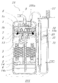
- FIG. 2 is a diagram schematically showing a cross section of the compressor unit according to Embodiment 1 of the present invention.
- the air conditioner 100 includes a compressor 21, a condenser 22, an expansion valve 23, an evaporator 24, an injection pipe 25, and an LEV 27.
- the compressor 21 compresses the sucked gas refrigerant, puts it in a high-temperature and high-pressure state, and conveys it to the refrigerant circuit.
- the high-temperature and high-pressure gas refrigerant discharged from the compressor 21 flows into the condenser 22.
- the high-temperature and high-pressure gas refrigerant that has flowed into the condenser 22 is heat-exchanged with air sent from a fan (not shown) disposed in the vicinity of the condenser 22, and becomes a gas-liquid two-phase refrigerant from the condenser 22. Leaked.
- the gas-liquid two-phase refrigerant that has flowed out of the condenser 22 is expanded and decompressed in the expansion valve 23 to become a low-temperature and low-pressure gas-liquid two-phase refrigerant.
- the low-temperature and low-pressure gas-liquid two-phase refrigerant flows into the evaporator 24.
- the gas-liquid two-phase refrigerant exchanges heat with air supplied from a fan (not shown) disposed in the vicinity of the evaporator 24 and evaporates to become a low-temperature and low-pressure gas refrigerant. leak.
- the low-temperature and low-pressure gas refrigerant that has flowed out of the evaporator 24 is sucked into the compressor 21.
- the compressor unit 101 includes a compressor 21 and an injection pipe 25.
- the compressor 21 has a shell 6 that is a sealed container.
- a frame 13 is disposed in the upper part of the shell 6, and a subframe 14 is disposed in the lower part.
- the frame 13 and the sub frame 14 are fixed to the inner peripheral surface of the shell 6 by shrink fitting, welding, or the like.
- a main bearing 13 a is provided in the through hole formed in the central portion of the frame 13, and a sub bearing 14 a is provided in the through hole formed in the central portion of the sub frame 14.
- the crankshaft 3 is rotatably supported by the main bearing 13a and the auxiliary bearing 14a.
- the compression mechanism provided with the fixed scroll 1 and the swing scroll 2 is arrange
- the fixed scroll 1 is arranged on the upper side and fixed to the shell 6 via a frame 13.
- the orbiting scroll 2 is disposed on the lower side and is supported on the crankshaft 3 so as to be able to swing.
- the fixed scroll 1 and the orbiting scroll 2 each have a spiral created by an involute curve.
- the spiral of the fixed scroll 1 and the spiral of the orbiting scroll 2 are meshed with each other, and a plurality of compression chambers 7 are formed.
- the fixed scroll 1 is provided with an injection port 1b. Further, the fixed scroll 1 is detachably attached with a component 10 for connecting to the injection tube 25. The refrigerant guided by the injection pipe 25 is injected into the compression chamber 7 through the injection port 1b.
- a driving mechanism including a rotor 4 and a stator 5 is disposed.
- the stator 5 has a substantially cylindrical shape, and the outer peripheral surface is fixed to the shell 6 by shrink fitting or the like.
- the rotor 4 is fixed to the outer periphery of the crankshaft 3, has a permanent magnet inside, and is rotatably held inside the stator 5 with a slight gap from the stator 5.
- the rotor 4 is rotationally driven by energizing the stator 5 to rotate the crankshaft 3.
- rotational power is transmitted to the above-described compression mechanism via the crankshaft 3.
- the orbiting scroll 2 performs a turning motion.
- the compression chamber 7 moves while reducing the volume toward the center along with the turning motion of the orbiting scroll 2, and compresses the refrigerant.
- the shell 6 is provided with a suction pipe (not shown) for sucking the refrigerant and a discharge pipe 9 for discharging the refrigerant.
- the refrigerant flowing out of the evaporator 24 is sucked from the suction pipe, fills the inside of the shell 6 and then sucked into the compression chamber 7. After being compressed in the compression chamber 7, the refrigerant passes through the discharge port 1 a, the connection member 8 that connects the discharge port 1 a and the discharge pipe 9, and is discharged out of the shell 6 through the discharge pipe 9.
- the injection pipe 25 branches a part of the refrigerant that flows out from the condenser 22 and is sent to the expansion valve 23 and returns it to the compression chamber 7 of the compressor 21.
- the injection pipe 25 branches a part of the refrigerant that flows out from the condenser 22 and is sent to the expansion valve 23 and returns it to the compression chamber 7 of the compressor 21.
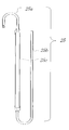
- FIG. 3 is a configuration diagram of the injection pipe according to Embodiment 1 of the present invention.
- the injection pipe 25 includes a compressor connection part 25a, an expansion valve connection part 25b, and an injection muffler 25c.
- the compressor connecting portion 25a is connected to the compressor 21, and the expansion valve connecting portion 25b is connected to the LEV 27.
- the injection muffler 25c is disposed between the compressor connection portion 25a and the expansion valve connection portion 25b.
- the compressor connecting portion 25a, the expansion valve connecting portion 25b, and the injection muffler 25c all have a cylindrical shape. As shown in FIG.
- the inner diameter (tube diameter) of the compressor connecting portion 25a is ⁇ d1
- the inner diameter of the expansion valve connecting portion 25b is ⁇ d2
- the inner diameter ⁇ muff of the injection muffler 25c ⁇ d1 ⁇ ⁇ muff and ⁇ d2 ⁇ ⁇ muff.
- the carbon dioxide refrigerant has a higher compression ratio in order to increase its capacity, so that the pressure for sending the liquid refrigerant and the pressure flowing back from the injection port 1b also become higher.
- the pressure generated in the injection pipe 25 increases, and at the same time, the pulsation generated in the injection pipe 25 also increases.
- the injection muffler 25c having an inner diameter equal to or larger than the inner diameter of the compressor connecting portion 25a and the expansion valve connecting portion 25b of the injection pipe 25 is provided in the injection circuit connecting the compressor 21 and the LEV 27. Intervene. Therefore, even when carbon dioxide refrigerant is used, pulsation generated in the injection pipe 25 can be reduced.
- FIG. 4 is a side view of the compressor and the injection pipe of the compressor unit according to Embodiment 1 of the present invention.
- FIG. 5 is a view showing an injection muffler attachment mechanism according to Embodiment 1 of the present invention.
- the injection pipe 25 is disposed such that the injection muffler 25 c is along the outer peripheral surface of the shell 6, that is, the side surface of the compressor 21.
- the compressor connecting portion 25a extends upward from the connecting portion with the compressor 21, is bent in the horizontal direction, and is further bent downward. That is, the compressor connecting portion 25a is bent twice and has an inverted U-shape as a whole.
- the injection muffler 25c that is continuous with the compressor connecting portion 25a extends in the vertical direction along the outer peripheral surface of the shell 6 of the compressor 21.
- the expansion valve connecting portion 25b that is continuous with the injection muffler 25c extends downward from the connection portion with the injection muffler 25c, is bent in the horizontal direction, and is further bent upward. That is, the injection muffler 25c has a U-shaped portion where the pipe is bent twice. A portion bent upward is extended to LEV27. As described above, in the first embodiment, the injection pipe 25 is bent four times as a whole.
- the portion extending in the vertical direction in the compressor connection portion 25a, the portion extending in the vertical direction in the expansion valve connection portion 25b, and the injection muffler 25c extend in parallel with the axis of the compressor 21, respectively.
- FIG. 5 is a view showing an injection muffler attachment mechanism according to Embodiment 1 of the present invention.
- the attachment mechanism 30 includes a fixed sheet metal 31 and a holding sheet metal 32.
- the fixed metal plate 31 is a thin plate-like member having a substantially U-shaped cross section, and is fixed on the outer peripheral surface of the shell 6 by welding.
- the fixed metal plate 31 has a pair of side surfaces 31a and 31b extending in parallel and an attachment surface 31c connecting the pair of side surfaces 31a and 31b.
- the fixed metal plate 31 is disposed on the outer peripheral surface of the shell 6 so that the side surfaces 31a and 31b extend in the vertical direction.
- the holding metal plate 32 is a belt-like member, and is raised at the approximate center in the longitudinal direction.
- a sandwiching portion 32c having a shape corresponding to a part of the cylindrical member is formed between the left and right end portions 32a and 32b.
- the holding sheet metal 32 is placed on the mounting surface 31 c of the fixed sheet metal 31, and the injection muffler 25 c is sandwiched between the mounting surface 31 c of the fixed sheet metal 31 and the clamping portion 32 c of the holding sheet metal 32.
- the end 32a of the holding metal plate 32 is fixed to the mounting surface 31c of the fixing metal plate 31 by the screw 41, and the end 32b of the holding metal plate 32 is screwed. 42 is fixed to the mounting surface 31 c of the fixed metal plate 31.
- the configuration of the injection muffler 25c will be described. If the inner diameter of the injection muffler 25c is increased, it is easy to secure the volume inside the injection muffler 25c, and pulsation can be easily reduced. However, the injection muffler 25c is fixed and the space inside the casing of the air conditioner 100 is limited, so that the installation is difficult depending on the size of the injection muffler 25c. Further, an unnecessary increase in diameter may lead to an increase in vibration accompanying an increase in the weight of the injection muffler 25c. From the above, it is important to determine the inner diameter and the total length of the injection muffler 25c after determining the minimum volume necessary to reduce pulsation.
- the diameter of the injection port 1 b is ⁇ port
- the injection pipe 25 is continuous with the compressor connecting portion 25 a
- the tip portion 250 a disposed inside the compressor 21.
- ⁇ d2 is the inner diameter of the expansion valve connecting portion 25b of the injection pipe 25
- ⁇ muff is the inner diameter of the injection muffler 25c.
- the injection tube 25 is configured to satisfy ⁇ port ⁇ ⁇ inj ⁇ ⁇ d1 ⁇ ⁇ muff and ⁇ inj ⁇ ⁇ d2 ⁇ ⁇ muff. In this way, the injection pulsation can be reduced by interposing the injection muffler 25c having an inner diameter larger than the inner diameter of the compressor connecting portion 25a and the inner diameter of the expansion valve connecting portion 25b in the injection pipe 25.
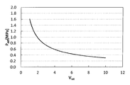
- FIG. 6 is a graph showing the correlation between the volume of the injection muffler and the pulsation width generated in the injection tube.
- the appropriate shape of the injection muffler 25c with respect to the displacement of the compressor will be described with reference to FIG.
- the horizontal axis represents the ratio Vrat (Vmuff / Vst) of the injection muffler volume Vmuff to the compressor displacement Vst
- the vertical axis represents the maximum value Pmax and the minimum value Pmin of the pulsation generated in the injection pipe.
- the difference Pdiff (Pmax ⁇ Pmin) is taken.
- the injection muffler 25c of the first embodiment is configured to have a relationship of 3 ⁇ Vrat ⁇ 5.
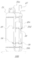
- FIG. FIG. 7 is a diagram showing a compressor unit according to Embodiment 2 of the present invention.
- an injection muffler 25d is provided at a portion extending upward toward the LEV 27 in the expansion valve connecting portion 25b.
- the injection muffler 25c and the injection muffler 25d are fixed to the outer peripheral surface of the compressor 21 at two locations by the attachment mechanism 30 as in the first embodiment.
- the installation space for the compressor occupied in the air conditioner housing can be secured while securing the volume of the injection muffler by installing two injection mufflers. It is possible to save, and the degree of freedom of the installation configuration inside the air conditioner can be increased.
- the injection muffler volume Vmuff is the total volume of pipes and components for the purpose of the muffler effect.
- the injection muffler 25c and the injection muffler 25d are securely held on the outer peripheral surface of the shell 6 of the compressor 21 via the mounting mechanism 30. Therefore, vibration and noise generated in the injection pipe 25 are reduced, and pipe cracking can be prevented in advance.
- the holding sheet metal 32 on which the injection mufflers 25c and 25d are held is fixed to the fixed sheet metal 31 fixed to the outer peripheral surface of the shell 6 of the compressor 21 with screws 41, It is screwed by 42 and is detachable from the fixed metal plate 31. Therefore, even when some trouble occurs in the injection tube 25 and it is necessary to replace it, the injection tube 25 can be easily removed.
- the attachment mechanism 30 holds the injection muffler 25c, 25d between the attachment surface 31c of the fixed metal plate 31 and the holding portion 32c of the holding metal plate 32, and the holding metal plate 32 is fixed to the fixed metal plate 31 by the screws 41 and 42. It has the structure to fix. Therefore, by tightening or loosening the screws 41 and 42, the injection mufflers 25c and 25d can be easily attached and detached, and good workability can be obtained.
- the injection pipe 25 is bent at four places, but is not limited thereto.
- the pipes may be bent as appropriate in consideration of the space restrictions in the casing of the air conditioner or the like in which the compressor units 101 and 102 are disposed and the positions where the injection mufflers 25c and 25d are disposed.
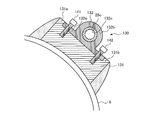
- FIG. 8 is a diagram showing a modification of the injection muffler attachment mechanism in the first embodiment.
- the attachment mechanism 130 has a fixed sheet metal 131 and a holding sheet metal 132.
- the fixed metal plate 131 is a substantially rectangular parallelepiped member, and is fixed on the outer peripheral surface of the shell 6 by welding.
- the surface of the fixed metal plate 131 that is in contact with the shell 6 is formed in an arc shape so as to follow the outer peripheral surface of the shell 6.
- a pair of wall portions 131a and 131b extending in parallel are formed on the surface of the fixed sheet metal 131 opposite to the surface in contact with the shell 6 to form a U-shaped cross-sectional shape.
- the fixed sheet metal 131 is disposed on the outer peripheral surface of the shell 6 so that the walls 131a and 131b extend in the vertical direction.
- the holding metal plate 132 has a plate-like base portion 132a and a cylindrical holding portion 132b formed integrally with the base portion 132a.
- the holding metal plate 132 is fixed to the fixed metal plate 131 by screws 141 and 142 in a state where the base portion 132a is sandwiched between the pair of wall portions 131a and 131b of the fixed metal plate 131 so that the axis of the holding portion 132b extends in the vertical direction. It is fixed.
- the injection muffler 25c is inserted through the hole 132c of the holding portion 132b.
- the fixed sheet metal 131 is a substantially rectangular parallelepiped member, it is firmly fixed to the outer peripheral surface of the shell 6 by welding.
- the injection muffler 25c may be sandwiched between the substantially rectangular parallelepiped fixed sheet metal 131 and the band-shaped holding sheet metal using a holding sheet metal having the same configuration as the above-described band-shaped holding sheet metal 32. .
Landscapes
- Engineering & Computer Science (AREA)
- Mechanical Engineering (AREA)
- General Engineering & Computer Science (AREA)
- Physics & Mathematics (AREA)
- Thermal Sciences (AREA)
- Compressor (AREA)
- Applications Or Details Of Rotary Compressors (AREA)
- Rotary Pumps (AREA)
Abstract
Description
図1は、本発明の実施の形態1に係る空気調和機の冷凍サイクルの概略構成図である。図2は、本発明の実施の形態1に係る圧縮機ユニットの断面を模式的に示す図である。空気調和装置100は、圧縮機21と、凝縮器22と、膨張弁23と、蒸発器24と、インジェクション管25と、LEV27とを備えている。圧縮機21は吸入されたガス冷媒を圧縮し、高温高圧の状態にして冷媒回路に搬送するものであり、例えば密閉型のスクロール圧縮機で構成される。圧縮機21から吐出された高温高圧のガス冷媒は、凝縮器22に流入される。凝縮器22に流入された高温高圧のガス冷媒は、凝縮器22の近傍に配置されたファン(図示せず)から送られる空気と熱交換され、気液二相冷媒となって凝縮器22から流出される。凝縮器22から流出された気液二相冷媒は、膨張弁23において膨張され減圧され、低温低圧の気液二相冷媒となる。低温低圧の気液二相冷媒は蒸発器24に流入される。蒸発器24において、気液二相冷媒は蒸発器24の近傍に配置されたファン(図示せず)から供給される空気と熱交換され、蒸発し、低温低圧のガス冷媒となり、蒸発器24から流出する。蒸発器24から流出した低温低圧のガス冷媒は、圧縮機21に吸入される。
図7は、本発明の実施の形態2に係る圧縮機ユニットを示す図である。図7に示すように、本実施の形態2の圧縮機ユニット102では、インジェクションマフラ25cに加え、膨張弁接続部25bにおいてLEV27へ向かって上方に延びる部分にインジェクションマフラ25dが設けられている。インジェクションマフラ25cおよびインジェクションマフラ25dは、上述の実施の形態1と同様、取付機構30により圧縮機21の外周面にそれぞれ2箇所で固定されている。
Claims (7)
- 圧縮機と、
凝縮器と、
前記圧縮機と前記凝縮器とを接続している冷媒配管において前記凝縮器から流出される冷媒を分岐させて、前記圧縮機に流入させるインジェクション管とを備え、
前記インジェクション管は、
前記圧縮機に接続される圧縮機接続部と、
前記インジェクション管に配設された膨張弁に接続される膨張弁接続部と、
前記圧縮機接続部と前記膨張弁接続部との間に配設されているインジェクションマフラとを有し、
前記インジェクションマフラの内径は、前記圧縮機接続部の内径および前記膨張弁接続部の内径よりも大きく、前記インジェクションマフラは前記圧縮機の側面に固定されている圧縮機ユニット。 - 前記インジェクション管は、前記圧縮機接続部に連続しており、前記圧縮機の内部に配置されている先端部を有し、
前記圧縮機は、前記インジェクション管の前記先端部を介して流入された前記冷媒を前記圧縮機の圧縮室へ導くインジェクションポートを有しており、
前記インジェクションポートの内径をφport、前記先端部の内径をφinj、前記圧縮機接続部の内径をφd1、前記膨張弁接続部の内径をφd2、前記インジェクションマフラの内径をφmuffとすると、φport≦φinj≦φd1≦φmuff及びφinj≦φd2≦φmuffを満たし、かつ、
圧縮機押しのけ量をVstとし、インジェクションマフラ容積をVmuffとし、前記圧縮機押しのけ量に対する前記インジェクションマフラ容積の比(Vmuff/Vst)をVratとすると、3≦Vrat≦5の関係を満たしている請求項1に記載の圧縮機ユニット。 - 前記インジェクション管は4箇所曲げで構成されており、かつ、前記インジェクションマフラは、前記圧縮機に少なくとも2箇所で固定されている請求項1または2に記載の圧縮機ユニット。
- さらに前記インジェクションマフラを前記圧縮機に固定する固定機構を有し、
前記固定機構は、前記圧縮機の側面に固定された固定部と、前記インジェクションマフラを保持する保持部とを有し、
前記保持部は前記固定部に着脱自在に取り付けられている請求項1~3のいずれか1項に記載の圧縮機ユニット。 - 前記固定部は、前記圧縮機の側面に溶接されたものである請求項4に記載の圧縮機ユニット。
- 前記保持部は前記固定部にねじ止めされている請求項4または5に記載の圧縮機ユニット。
- 前記冷媒は二酸化炭素である請求項1~6のいずれか1項に記載の圧縮機ユニット。
Priority Applications (4)
| Application Number | Priority Date | Filing Date | Title |
|---|---|---|---|
| EP16902399.1A EP3460244B1 (en) | 2016-05-18 | 2016-05-18 | Compressor unit |
| PCT/JP2016/064786 WO2017199380A1 (ja) | 2016-05-18 | 2016-05-18 | 圧縮機ユニット |
| JP2018518008A JPWO2017199380A1 (ja) | 2016-05-18 | 2016-05-18 | 圧縮機ユニット |
| KR1020187029461A KR20180121623A (ko) | 2016-05-18 | 2016-05-18 | 압축기 유닛 |
Applications Claiming Priority (1)
| Application Number | Priority Date | Filing Date | Title |
|---|---|---|---|
| PCT/JP2016/064786 WO2017199380A1 (ja) | 2016-05-18 | 2016-05-18 | 圧縮機ユニット |
Publications (1)
| Publication Number | Publication Date |
|---|---|
| WO2017199380A1 true WO2017199380A1 (ja) | 2017-11-23 |
Family
ID=60325074
Family Applications (1)
| Application Number | Title | Priority Date | Filing Date |
|---|---|---|---|
| PCT/JP2016/064786 Ceased WO2017199380A1 (ja) | 2016-05-18 | 2016-05-18 | 圧縮機ユニット |
Country Status (4)
| Country | Link |
|---|---|
| EP (1) | EP3460244B1 (ja) |
| JP (1) | JPWO2017199380A1 (ja) |
| KR (1) | KR20180121623A (ja) |
| WO (1) | WO2017199380A1 (ja) |
Cited By (1)
| Publication number | Priority date | Publication date | Assignee | Title |
|---|---|---|---|---|
| CN112761954A (zh) * | 2021-02-01 | 2021-05-07 | 珠海格力节能环保制冷技术研究中心有限公司 | 一种排气消音组件、压缩机和空调器 |
Citations (2)
| Publication number | Priority date | Publication date | Assignee | Title |
|---|---|---|---|---|
| JPS61261693A (ja) * | 1985-05-16 | 1986-11-19 | Mitsubishi Electric Corp | スクロ−ル圧縮機 |
| JP2010185406A (ja) * | 2009-02-13 | 2010-08-26 | Mitsubishi Heavy Ind Ltd | インジェクション管 |
Family Cites Families (4)
| Publication number | Priority date | Publication date | Assignee | Title |
|---|---|---|---|---|
| JP2003286945A (ja) * | 2002-03-28 | 2003-10-10 | Sanyo Electric Co Ltd | コンプレッサ |
| US20090116977A1 (en) * | 2007-11-02 | 2009-05-07 | Perevozchikov Michael M | Compressor With Muffler |
| JP5126402B2 (ja) * | 2010-10-29 | 2013-01-23 | ダイキン工業株式会社 | スクリュー圧縮機 |
| JP6038287B2 (ja) * | 2013-03-28 | 2016-12-07 | 三菱電機株式会社 | スクロール圧縮機及びそれを備えた冷凍サイクル装置 |
-
2016
- 2016-05-18 WO PCT/JP2016/064786 patent/WO2017199380A1/ja not_active Ceased
- 2016-05-18 EP EP16902399.1A patent/EP3460244B1/en active Active
- 2016-05-18 JP JP2018518008A patent/JPWO2017199380A1/ja active Pending
- 2016-05-18 KR KR1020187029461A patent/KR20180121623A/ko not_active Ceased
Patent Citations (2)
| Publication number | Priority date | Publication date | Assignee | Title |
|---|---|---|---|---|
| JPS61261693A (ja) * | 1985-05-16 | 1986-11-19 | Mitsubishi Electric Corp | スクロ−ル圧縮機 |
| JP2010185406A (ja) * | 2009-02-13 | 2010-08-26 | Mitsubishi Heavy Ind Ltd | インジェクション管 |
Cited By (1)
| Publication number | Priority date | Publication date | Assignee | Title |
|---|---|---|---|---|
| CN112761954A (zh) * | 2021-02-01 | 2021-05-07 | 珠海格力节能环保制冷技术研究中心有限公司 | 一种排气消音组件、压缩机和空调器 |
Also Published As
| Publication number | Publication date |
|---|---|
| EP3460244B1 (en) | 2020-03-11 |
| EP3460244A1 (en) | 2019-03-27 |
| JPWO2017199380A1 (ja) | 2018-12-06 |
| KR20180121623A (ko) | 2018-11-07 |
| EP3460244A4 (en) | 2019-03-27 |
Similar Documents
| Publication | Publication Date | Title |
|---|---|---|
| EP2594737A2 (en) | Rotary Compressor and Manufacturing Method Thereof | |
| US10989196B2 (en) | Compressor having muffler function | |
| WO2010092933A1 (ja) | インジェクション管 | |
| CN1842685B (zh) | 用于最小化压力脉动的节省器腔室 | |
| WO2017199380A1 (ja) | 圧縮機ユニット | |
| KR101718037B1 (ko) | 밀폐형 압축기 | |
| WO2016139873A1 (ja) | 圧縮機 | |
| CN117980603A (zh) | 压缩机单元 | |
| WO2022004597A1 (ja) | 熱源ユニットおよびスクロール圧縮機 | |
| KR20100083257A (ko) | 냉동유니트 및 히트펌프용 압축기의 역회전 방지장치 및 그제어방법 | |
| US20140377107A1 (en) | Hermetic compressor with discharge pulsation reducing member mounted thereon | |
| CN104948466B (zh) | 旋转压缩机及具有其的冷冻循环装置 | |
| US20150125322A1 (en) | Rotary compressor | |
| JP5595324B2 (ja) | 圧縮機 | |
| KR200382915Y1 (ko) | 압축기용 어큐뮬레이터의 연결 구조 | |
| US20200347846A1 (en) | Compressor and refrigeration cycle apparatus | |
| CN204783675U (zh) | 旋转压缩机及具有其的冷冻循环装置 | |
| KR880001155Y1 (ko) | 밀폐형 압축기의 냉매가스 흡입 순환기 | |
| JP6749183B2 (ja) | スクロール圧縮機 | |
| JP2008298413A (ja) | ターボ冷凍機 | |
| JP2009097460A (ja) | 回転式電動圧縮機 | |
| KR100782882B1 (ko) | 배관 연결구조 | |
| JP2017089507A (ja) | 圧縮機 | |
| CN102197225A (zh) | 密闭型压缩机 | |
| WO2018043329A1 (ja) | スクロール圧縮機 |
Legal Events
| Date | Code | Title | Description |
|---|---|---|---|
| WWE | Wipo information: entry into national phase |
Ref document number: 2018518008 Country of ref document: JP |
|
| ENP | Entry into the national phase |
Ref document number: 20187029461 Country of ref document: KR Kind code of ref document: A |
|
| NENP | Non-entry into the national phase |
Ref country code: DE |
|
| 121 | Ep: the epo has been informed by wipo that ep was designated in this application |
Ref document number: 16902399 Country of ref document: EP Kind code of ref document: A1 |
|
| ENP | Entry into the national phase |
Ref document number: 2016902399 Country of ref document: EP Effective date: 20181218 |