WO2017199498A1 - レーン特定方法およびレーン特定装置 - Google Patents
レーン特定方法およびレーン特定装置 Download PDFInfo
- Publication number
- WO2017199498A1 WO2017199498A1 PCT/JP2017/005875 JP2017005875W WO2017199498A1 WO 2017199498 A1 WO2017199498 A1 WO 2017199498A1 JP 2017005875 W JP2017005875 W JP 2017005875W WO 2017199498 A1 WO2017199498 A1 WO 2017199498A1
- Authority
- WO
- WIPO (PCT)
- Prior art keywords
- image
- lane
- line
- processor
- contour
- Prior art date
- Legal status (The legal status is an assumption and is not a legal conclusion. Google has not performed a legal analysis and makes no representation as to the accuracy of the status listed.)
- Ceased
Links
Images



Classifications
-
- G—PHYSICS
- G06—COMPUTING OR CALCULATING; COUNTING
- G06T—IMAGE DATA PROCESSING OR GENERATION, IN GENERAL
- G06T7/00—Image analysis
- G06T7/70—Determining position or orientation of objects or cameras
-
- G—PHYSICS
- G06—COMPUTING OR CALCULATING; COUNTING
- G06T—IMAGE DATA PROCESSING OR GENERATION, IN GENERAL
- G06T7/00—Image analysis
- G06T7/10—Segmentation; Edge detection
- G06T7/12—Edge-based segmentation
-
- G—PHYSICS
- G06—COMPUTING OR CALCULATING; COUNTING
- G06V—IMAGE OR VIDEO RECOGNITION OR UNDERSTANDING
- G06V20/00—Scenes; Scene-specific elements
- G06V20/50—Context or environment of the image
- G06V20/56—Context or environment of the image exterior to a vehicle by using sensors mounted on the vehicle
- G06V20/588—Recognition of the road, e.g. of lane markings; Recognition of the vehicle driving pattern in relation to the road
-
- H—ELECTRICITY
- H04—ELECTRIC COMMUNICATION TECHNIQUE
- H04N—PICTORIAL COMMUNICATION, e.g. TELEVISION
- H04N7/00—Television systems
- H04N7/18—Closed-circuit television [CCTV] systems, i.e. systems in which the video signal is not broadcast
-
- G—PHYSICS
- G06—COMPUTING OR CALCULATING; COUNTING
- G06T—IMAGE DATA PROCESSING OR GENERATION, IN GENERAL
- G06T2207/00—Indexing scheme for image analysis or image enhancement
- G06T2207/30—Subject of image; Context of image processing
- G06T2207/30248—Vehicle exterior or interior
- G06T2207/30252—Vehicle exterior; Vicinity of vehicle
- G06T2207/30256—Lane; Road marking
Definitions
- This disclosure relates to a lane identification method and apparatus.
- a moving body tracking device for tracking a moving body in an image.
- the predicted position of the moving object in the current frame image is obtained based on the position information of the moving object in the past frame image.
- candidate objects having predetermined characteristics peculiar to the moving object are extracted from the image data in the current frame image, and candidate objects closer to the predicted position among the extracted candidate objects are assigned as the moving object.
- the present disclosure relates to a method and apparatus for accurately identifying a lane region existing in an image.
- the processor identifies a lane region existing in an image based on a pattern in which information obtained based on the contour of an object in the image appears in the image.
- the lane identification method and the lane identification device according to the present disclosure are effective for accurately identifying the lane region existing in the image.
- FIG. 1 is a diagram illustrating how the lane identification device according to the first embodiment is used.
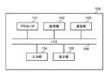
- FIG. 2 is a diagram illustrating a configuration of the lane identification device according to the first embodiment.
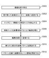
- FIG. 3 is a flowchart for explaining the operation of the lane identification device according to the first embodiment.
- FIG. 4 is a diagram illustrating an image to be processed in the first embodiment.
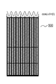
- FIG. 5 is a diagram showing a top view image in the first embodiment.
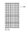
- FIG. 6 is a diagram illustrating a state in which the contour of an object in the top view image according to the first embodiment is line-divided.
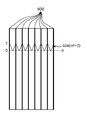
- FIG. 7 is a diagram showing a pattern calculation concept in the first embodiment.
- FIG. 8 is a diagram illustrating a state in which the lane region is specified based on the calculated pattern in the top view image according to the first embodiment.
- FIG. 1 is a diagram illustrating how the lane identification device according to the first embodiment is used.
- the lane identification device 100 is obtained by installing a lane identification program on a general-purpose computer.
- the lane identification device 100 is connected to the imaging device 200 so as to be communicable.
- the lane identification device 100 may be a dedicated embedded device or may be configured in hardware.
- the imaging device 200 is a video camera.
- the imaging apparatus 200 images the pool 300 from a bird's-eye view as shown in FIG.
- the moving image or image captured by the imaging device 200 is transmitted to the lane identification device 100.
- the pool 300 has a plurality of lanes.
- a plurality of course ropes 302 are stretched around the pool 300.
- FIG. 1 only the uppermost course rope is labeled, but the broken line in FIG. 1 represents the course rope.
- the course rope 302 is a mark for partitioning the lane.
- a pool is shown as an example of a stadium.
- the present disclosure accurately obtains a lane region existing in an image having lanes. Therefore, the target for which the lane area is specified is not limited to the pool.
- the present disclosure can be used to identify lanes on land tracks, roads, and the like. However, as will be described later, when the size or number of lanes for which the lane area is specified can be specified or assumed, the lane area can be specified with higher accuracy.
- the present disclosure makes it possible to particularly preferably specify a lane region for an image in which ripples or light reflection is likely to appear in an image, such as an image of a pool.
- FIG. 2 is a diagram illustrating a configuration of the lane identification device according to the first embodiment.
- the lane identification device 100 includes a processor 101, a storage unit 102, a communication unit 103, an input unit 104, a display unit 105, and a bus 106.
- the processor 101 controls other components of the lane identification device by performing calculations.
- the storage unit 102 stores information temporarily or permanently.
- the storage unit 102 corresponds to a ROM (Read Only Memory) or a RAM (Random Access Memory) of the lane identification device.
- the lane identification device 100 may include a plurality of storage units 102 depending on the application and the necessity of access speed.
- the storage unit 102 can be configured by applying HDD (Hard Disk Drive), SDRAM (Synchronous Dynamic Random Access Memory), SSD (Solid State Drive), or the like.
- the communication unit 103 is an interface that connects the lane identification device 100 and the imaging device 200.
- the communication unit 103 may be a wired connection interface or a wireless connection interface.
- the communication unit 103 is for transmitting a moving image or an image captured by the imaging device 200 to the lane identification device 100. Therefore, when moving a moving image or an image from the imaging device 200 to the lane specifying device 100 using the storage medium, the communication unit 103 is not an essential configuration.
- the input unit 104 receives an external signal.
- the input unit 104 corresponds to an input device or an input interface of the lane identification device 100.
- the input unit 104 can be configured by applying an input device such as a mouse or a keyboard, or an input interface such as a communication port or a wireless communication device.
- Display unit 105 displays information to the outside.
- the display unit 105 can be configured by applying a liquid crystal display or the like.
- the bus 106 is a path for connecting each element constituting the lane identification device 100.
- the bus 106 can be configured inside the processor 101 by integrating the bus 106 with the processor 101.
- Each element of the bus 106 may be connected by wire, or each element may be connected wirelessly.
- the configuration of the lane identification device 100 described above is an example. Therefore, the lane identification device 100 may be configured by adding another component to the configuration described above. Moreover, you may comprise the lane identification apparatus 100 by deleting a part of component from the structure described above as needed. In addition, the lane identification device 100 may be configured by integrating the components described above. Further, the lane identification device 100 may be configured by separating the above-described constituent elements into the above constituent elements.
- the operation of the lane identification device 100 described above will be described.
- the lane identification device 100 operates mainly when the processor 101 cooperates with each element of the lane identification device 100 to execute a program.
- FIG. 3 is a flowchart for explaining the operation of the lane identification device according to the first embodiment.
- step S300 the lane identification device 100 receives an image from the imaging device 200 via the communication unit 103.
- the received image becomes an image to be processed in the following operation.
- FIG. 4 is a diagram showing an image to be processed in the first embodiment.
- the imaging device 200 captures an image so that the pool 300 is looked down on. Therefore, as illustrated in FIG. 4, the image captured by the imaging apparatus 200 is an image in which the pool 300 appears to expand from the back to the front.
- FIG. 4 a plurality of course ropes 302 are stretched in the pool 300 as already described.
- FIG. 4 FIG. 5 is the same
- only the leftmost course rope is labeled, but in FIG. 4 (the same applies to FIG. 5), the broken line represents the course rope.
- a lane line 304 indicating the center of the lane is drawn on the bottom of the pool.
- FIG. 4 (FIG. 5 is also the same)
- the solid line adjacent to the course rope 302 represents the lane line.
- a cross line 306 orthogonal to the lane line 304 is drawn on the bottom surface of the pool.
- step S302 the processor 101 converts the image received in step S300 into a top view image.
- the top view image is an image of a composition (plan view) obtained when the object is looked down from directly above.
- the image captured by the imaging apparatus 200 is an image in which the pool 300 appears to expand from the back to the front.
- the pool 300 is originally rectangular in plan view.
- the processor 101 converts the image shown in FIG. 4 into a top view image in order to facilitate subsequent image processing. This process is not an indispensable process because it is performed to facilitate later image processing. Converting an image to a top view image is called top view conversion.
- a known method can be appropriately applied as a method for performing the top view conversion.
- the user of the lane identification device 100 uses the input unit 104 to specify the coordinates of the four corners of the trapezoidally distorted pool.
- the user designates coordinates 308, 310, 312, and 314 as four corner coordinates.
- coordinates including the course rope are designated as the coordinates of the four corners. This facilitates the processing in step S310 described later.
- step S310 can be facilitated by using the coordinates of the four corners as the intersections of an object (coarse rope or poolside) that partitions the pool and the front and rear front ends of the pool. it can.
- the processor 101 generates a coordinate transformation matrix such that the coordinates of the designated four points are rectangular.
- a top view image can be obtained by the processor 101 converting the coordinates of the pixels inside the coordinates of the four corners using the generated conversion matrix.
- FIG. 5 is a diagram showing a top view image in the first embodiment.
- the processor 101 converts the image captured by the imaging device 200 into the top view image 500. Note that the top-view conversion can be omitted even when the imaging apparatus 200 is installed at a location where imaging is performed in plan view. Further, the top view conversion need not be performed by the processor 101 of the lane identification device 100. Even when another processing device performs the top view conversion and transmits the image after the top view conversion to the lane specifying device, a result similar to the above-described operation can be obtained.
- step S304 the processor 101 extracts a luminance edge from the top view image converted in step S302. If top view conversion is omitted, luminance edges are extracted from the image received in step S300.
- the luminance edge is a portion where the luminance of the pixels constituting the image changes suddenly in the image.
- a typical example of the location where the change in pixel brightness is abrupt is the contour of an object.
- step S306 the processor 101 obtains the contour of the object by expanding and contracting the luminance edge extracted in step S304.
- the outline of the actual object is linear, whereas the luminance edge is often obtained as a sparse point in the image.
- the following processing is performed to bring the luminance edge closer to the actual contour of the object. First, if the pixel obtained as the luminance edge is at least one pixel within a predetermined range around a certain pixel in the image from which the luminance edge has been extracted, the processor 101 converts all the regions into luminance edge pixels. Replace (expansion process).
- the processor 101 deletes the region from the luminance edge pixel if even one luminance edge pixel is missing in the region of the predetermined range of the luminance edge pixel group connected by expansion (contraction processing). By doing so, the expanded and contracted luminance edge pixels can reproduce the contour of the object more accurately. Note that the brightness edge pixel reproduces the contour of the object more accurately by repeating the expansion process and the contraction process not only once but multiple times.
- steps S304 and S306 are applicable as long as the process can extract the contour of the object.
- the contour of the object may be extracted using a change in color information in the pixel, or the contour of the object may be obtained using a distance sensor.
- step S308 the processor 101 converts the contour of the object obtained in step S306 into a line segment.
- a known algorithm called probabilistic Hough transform is used as a method for converting a set of points in an image into a line segment in the image.
- the probabilistic Hough transform By using the probabilistic Hough transform, the coordinates of a set of points constituting a blurred or distorted line in the image are converted into coordinates constituting a smooth line.
- the contour in the image is obtained as a smooth line segment by performing probabilistic Hough transform on the points constituting the contour of the object obtained in step S306.
- the method of obtaining the line segment is not limited to the stochastic Hough transform.
- a line segment may be obtained by applying a blur filter to the contour of an object.
- the line segment may be obtained by further repeating the above-described expansion / contraction process on the contour of the object. Further, when a sufficient quality contour that can be regarded as a line segment is obtained in the processing up to step S306, the processing in step S308 may be omitted. Further, in the present disclosure, information to be obtained until step S308 is completed is not limited to a line segment. Information that should be obtained until step S308 is completed may be information that can be used as a target of processing in and after step S310. In the present disclosure, the information to be obtained until step S308 is completed may be a straight line including a part of the contour of the object, or may be a curve. In addition, a chain or mesh pattern may be used.
- a line is obtained from the image based on the contour of the object as in the present embodiment, there is an advantage that the amount of calculation for the subsequent processing can be reduced.
- a concept including a line segment, a straight line, and a curve is simply referred to as a line.
- a line segment can be obtained as information from the contour of the object in the top view image.
- FIG. 6 is a diagram showing a state in which the contour of the object in the top view image in the first embodiment is line-divided.
- the line 600 obtained by linearly dividing the contours of the course rope and the poolside can be clearly extracted by performing the above-described processing.
- a line including a line segment that appears at a coordinate that coincides with a location where an object that partitions the lane exists (such as a course rope or a poolside) in the image is referred to as a line that represents the object that partitions the lane.
- FIG. 6 it is difficult for the lane line and the cross line to be faithfully extracted due to the reflection of the water surface and the influence of waves.
- a final line segment is obtained by deleting a part of the set of line segments that are primarily obtained in step S308 based on the size of the pool (stadium). .
- the processor 101 determines a line segment having a length less than a value obtained by dividing the size (length) in the traveling direction in the pool (stadium) image by a predetermined value (8 in the present embodiment). Does the processing without deleting it as a line segment. By doing in this way, the line segment which does not seem to be the outline of the object which partitions the lane of a stadium can be removed from a final line segment. Therefore, the accuracy of specifying the lane area can be improved.
- step S310 the processor 101 calculates an appearance pattern in the image of the line segment obtained in step S308.
- an object course rope or poolside
- the predetermined pattern means a pattern resulting from the lane interval. For example, course ropes are stretched at equal intervals in the pool, and white lines are drawn at equal intervals on land tracks and roads.
- the coordinates of the object that partitions the lane are specified, and the areas between the objects that partition the lane are specified as individual lanes.
- step S310 is to identify the line 600 that appears according to a predetermined pattern.
- FIG. 7 is a diagram showing a pattern calculation concept in the first embodiment.
- the pattern is defined using the following formula defined by defining the horizontal coordinate after the top view conversion (the left end of the image is 0) as an angle and the vertical direction as a trigonometric ratio. calculate.
- the value of ⁇ is determined based on a parameter that assumes the number of lanes present in the image. Specifically, it is determined based on the following formula.
- ⁇ (assumed number of lanes) ⁇ 360 ⁇ (horizontal width of top view image) (Expression 2)
- the processor 101 determines the value of (Expression 2), thereby generating a graph that takes a peak corresponding to the number of lanes +1 assumed based on (Expression 1).
- the initial value of the number of lanes assumed here may be input by the user of the lane specifying apparatus 100 from the input unit 104, or may be recorded in the storage unit 102.
- the horizontal direction of the graph is adjusted based on (Expression 1), assuming that the graph is present in the top view image with a horizontal phase difference ⁇ . In this embodiment, the initial value of ⁇ is 0.
- step S310 can be suitably performed. Even when the top view conversion is not performed, the processing in step S310 can be suitably performed by shooting so that the course rope or the poolside is reflected at the left end of the image. Then, the processor 101 uses each of the horizontal coordinate values ⁇ of all the lines obtained in step S308 to obtain ⁇
- the value of ⁇ may be the value of the intermediate coordinate in the horizontal direction between the end points of all the lines obtained in step S308.
- the value of ⁇ is the horizontal coordinate of the entire course rope (the horizontal coordinate with periodicity).
- ⁇ is likely to be a random value without periodicity, so that the values of ⁇ and ⁇ are more It becomes easy to find accurately.
- the processor 101 obtains the value of (Expression 3) for the initial values of ⁇ and ⁇ , and then obtains the value of (Expression 3) for the value of ⁇ or ⁇ different from the initial value. Specifically, the processor 101 obtains the value of (Equation 3) by changing ⁇ to a value within a possible range of the number of lanes, which is about ⁇ 2 of the initial value. In the example of the pool, the general number of lanes is 6 to 10, so ⁇ may be changed in these ranges. Further, the processor 101 obtains a value of (Equation 3) by changing ⁇ from a default value of ⁇ 30 (degrees) to a value within the range of +30 (degrees).
- the processor 101 After obtaining the values of (Equation 3) for all combinations of ⁇ and ⁇ , the processor 101 identifies the combination of ⁇ and ⁇ that takes the largest value. (Expression 1) in which ⁇ and ⁇ specified in this way are substituted is used as an expression for calculating the appearance pattern.
- ⁇ is assumed not to take a value less than half of the maximum number (formula The calculation of 3) should be performed.
- the contour of the lane line is represented by the information indicating the object that partitions the lane (the contour of the course rope or the pool side is drawn as a line). This is because the possibility of erroneous recognition as a differentiated line 600) is reduced.
- Such a lower limit value of ⁇ may be obtained by the processor 101 from the maximum number of lanes as described above, or input to the lane identification device 100 via the input unit 104 by the user of the lane identification device 100. May be.
- the lane identification device 100 may be any device that identifies the lane region existing in the image based on the patterns obtained up to step S310. That is, the lane identification device 100 may perform the processing from step S312 onward after acquiring a pattern obtained by another processing device performing processing equivalent to the processing up to step S310 from the communication unit 103.
- the pattern calculation method is not limited to that described in the description of step S310.
- the pattern of the present disclosure may be a pattern in which the outline of an object appears. If a complicated pattern other than a line is captured as the outline of an object, the pattern may be calculated using a spectrum analysis or other known method. Good.
- step S312 the processor 101 specifies a lane region in the image based on the pattern calculated in step S310.
- FIG. 8 is a diagram illustrating a state in which the lane region is specified based on the calculated pattern in the top view image according to the first embodiment.
- the processor 101 synchronizes the horizontal coordinate of the calculated pattern with the horizontal coordinate of the top view image 500, and the top having the horizontal coordinate existing between the peak of the calculated pattern (starting point of the arrow in FIG. 8) and the adjacent peak.
- An area of the view image 500 is specified as one lane.
- the pattern since the pattern has eight peaks, a total of seven lanes are specified.
- the image in which the lane region is specified is not limited to the top view image. For example, it is possible to specify the lane in the image captured by the imaging apparatus 200 by performing the reverse process of step S302 on the top view image shown in FIG.
- the identified lane area can be used in various ways. For example, when displaying the top view image 500 or the image captured by the imaging device 200 on the display unit 105, the lane regions are displayed in different colors, thereby facilitating the editing work of the person in charge of the video editing work, or High sense of presence can be given to the viewer of the video.
- the attributes of a person or object existing in a specific lane are known, it is possible to emphasize which person or object exists in which lane by displaying the attribute superimposed on the lane area. it can. If a person or object in the lane is being tracked using image recognition technology, it can be tracked by specifying in which lane area the person or object being tracked exists. It is also possible to specify the attributes of a person or object.
- step S302 when the image received in step S300 is converted into a top view image, if the conversion that rotates the image by 90 degrees is also added together with the keystone correction, the processing in step S304 and subsequent steps can be similarly performed. it can.
- the processor 101 of the lane identification device 100 uses the lane region existing in the image based on the pattern in which the information obtained based on the contour of the object in the image appears in the image. Is identified.
- the object in the image is an object that partitions the lane.
- the lane area is specified based on the appearance pattern of the object that realistically describes the lane area. Therefore, it is possible to specify the lane region existing in the image with higher accuracy.
- the information obtained based on the contour of the object in the image is a line representing the object that partitions the lane.
- the line representing the object that partitions the lane is obtained based on the size of the stadium existing in the image.
- lines resulting from noise in the image can be eliminated, so that the lane region existing in the image can be specified more accurately.
- the pattern is calculated based on a parameter that assumes the number of lanes present in the image.
- the present disclosure can be applied to a method or apparatus for identifying a lane area in a video.
- the present invention can be applied to a computer for handling sports video analysis.
Landscapes
- Engineering & Computer Science (AREA)
- Physics & Mathematics (AREA)
- General Physics & Mathematics (AREA)
- Theoretical Computer Science (AREA)
- Multimedia (AREA)
- Computer Vision & Pattern Recognition (AREA)
- Signal Processing (AREA)
- Image Analysis (AREA)
- Closed-Circuit Television Systems (AREA)
- Image Processing (AREA)
Abstract
Description
以下、図1~8を用いて、実施の形態1を説明する。
図1は、実施の形態1におけるレーン特定装置の使用の様子を示す図である。
以上に述べたレーン特定装置100の動作を説明する。なお、レーン特定装置100は主としてプロセッサ101がレーン特定装置100の各要素と協業してプログラムを実行することで動作するものである。
(式1)が線600が出現する水平座標(θ)において1(ピーク)に近い値をなるべく多く取るように、αおよびβを求める。そして求めたαおよびβを代入した(式1)を、出現パターンを算出する式として用いる。
プロセッサ101は、(式2)の値を定めることで、(式1)に基づいて仮定するレーン数+1個分のピークを取るグラフを生成する。ここで仮定するレーン数の初期値は入力部104からレーン特定装置100のユーザによって入力されても良いし、記憶部102に記録されているものを用いても良い。続いて、当該グラフがトップビュー画像中に水平方向の位相差βで存在するとして、(式1)に基づいてグラフの水平方向を調整する。本実施の形態ではβの初期値は0とする。なお、トップビュー変換の際に4隅の座標としてコースロープやプールサイドを含む座標を指定していると、βの真の値が0に近づくためステップS310の処理を好適に行うことができる。トップビュー変換を行わない際も画像の左端にコースロープやプールサイドが映るように撮影を行うとステップS310の処理を好適に行うことができる。そして、プロセッサ101は、ステップS308で得られたすべての線の水平方向の座標値θそれぞれを用いて
Σ|cos(αθ+β)| ・・・(式3)
を求める演算をする。
以上のように、本実施の形態において、レーン特定装置100のプロセッサ101は、画像中の物体の輪郭に基づいて得られる情報が画像中において現れるパターンに基づいて画像の中に存在するレーンの領域を特定する。
101 プロセッサ
102 記憶部
103 通信部
104 入力部
105 表示部
106 バス
200 撮像装置
300 プール
302 コースロープ
304 レーンライン
306 クロスライン
308 座標
310 座標
312 座標
314 座標
500 トップビュー画像
600 線
Claims (10)
- プロセッサが画像の中に存在するレーンの領域を特定する方法であって、
前記プロセッサは、
画像中の物体の輪郭に基づいて得られる情報が前記画像中において現れるパターンに基づいて前記画像の中に存在するレーンの領域を特定する、
レーン特定方法。 - 前記画像中の物体はレーンを仕切る物体である、
請求項1に記載のレーン特定方法。 - 前記画像中の物体の輪郭に基づいて得られる情報は、前記レーンを仕切る物体を表す線である、
請求項2に記載のレーン特定方法。 - 前記線は、前記画像の中に存在する競技場のサイズに基づいて前記画像から得られる、
請求項3に記載のレーン特定方法。 - 前記パターンは、前記画像の中に存在するレーン数を仮定するパラメータを基に算出される、
請求項1に記載のレーン特定方法。 - 画像の中に存在するレーンの領域を特定する装置であって、
前記装置のプロセッサは、
画像中の物体の輪郭に基づいて得られる情報が前記画像中において現れるパターンに基づいて前記画像の中に存在するレーンの領域を特定する、
レーン特定装置。 - 前記画像中の物体はレーンを仕切る物体である、
請求項6に記載のレーン特定装置。 - 前記画像中の物体の輪郭に基づいて得られる情報は、前記レーンを仕切る物体を表す線である、
請求項7に記載のレーン特定装置。 - 前記線は、前記画像の中に存在する競技場のサイズに基づいて前記画像から得られる、
請求項8に記載のレーン特定装置。 - 前記パターンは、前記画像の中に存在するレーン数を仮定するパラメータを基に算出される、
請求項6に記載のレーン特定装置。
Priority Applications (4)
| Application Number | Priority Date | Filing Date | Title |
|---|---|---|---|
| CN201780028669.3A CN109074662A (zh) | 2016-05-18 | 2017-02-17 | 分道确定方法以及分道确定装置 |
| EP17798936.5A EP3460755A4 (en) | 2016-05-18 | 2017-02-17 | METHOD FOR TRAVEL SPECIFICATION AND DEVICE FOR TRAVEL SPECIFICATION |
| US16/300,425 US11087486B2 (en) | 2016-05-18 | 2017-02-17 | Lane specification method and lane specification device |
| JP2018518086A JP6956325B2 (ja) | 2016-05-18 | 2017-02-17 | レーン特定方法およびレーン特定装置 |
Applications Claiming Priority (2)
| Application Number | Priority Date | Filing Date | Title |
|---|---|---|---|
| JP2016099368 | 2016-05-18 | ||
| JP2016-099368 | 2016-05-18 |
Publications (1)
| Publication Number | Publication Date |
|---|---|
| WO2017199498A1 true WO2017199498A1 (ja) | 2017-11-23 |
Family
ID=60324967
Family Applications (1)
| Application Number | Title | Priority Date | Filing Date |
|---|---|---|---|
| PCT/JP2017/005875 Ceased WO2017199498A1 (ja) | 2016-05-18 | 2017-02-17 | レーン特定方法およびレーン特定装置 |
Country Status (5)
| Country | Link |
|---|---|
| US (1) | US11087486B2 (ja) |
| EP (1) | EP3460755A4 (ja) |
| JP (1) | JP6956325B2 (ja) |
| CN (1) | CN109074662A (ja) |
| WO (1) | WO2017199498A1 (ja) |
Cited By (1)
| Publication number | Priority date | Publication date | Assignee | Title |
|---|---|---|---|---|
| JP2024500688A (ja) * | 2020-12-09 | 2024-01-10 | バリック マルティナ | 移動可能な物体の三次元位置を決定するための位置決めシステム及び方法 |
Families Citing this family (5)
| Publication number | Priority date | Publication date | Assignee | Title |
|---|---|---|---|---|
| WO2018198693A1 (ja) * | 2017-04-25 | 2018-11-01 | 富士フイルム株式会社 | 画像処理装置、撮像装置、画像処理方法、およびプログラム |
| US10803723B2 (en) * | 2019-06-27 | 2020-10-13 | Darryl L Hurt | Safety apparatus for a water body |
| JP7322549B2 (ja) * | 2019-06-28 | 2023-08-08 | セイコーエプソン株式会社 | 画像処理方法および画像処理装置 |
| KR20210112672A (ko) * | 2020-03-05 | 2021-09-15 | 삼성전자주식회사 | 객체를 검출하기 위한 프로세서 및 객체 검출 방법 |
| CN114092891B (zh) * | 2020-07-02 | 2024-09-20 | 上海际链网络科技有限公司 | 区域占用的分析方法及装置、存储介质、计算机设备 |
Citations (3)
| Publication number | Priority date | Publication date | Assignee | Title |
|---|---|---|---|---|
| JP2003123058A (ja) * | 2001-10-17 | 2003-04-25 | Hitachi Ltd | 走行レーン認識装置 |
| JP2016018540A (ja) * | 2014-07-11 | 2016-02-01 | 株式会社日本自動車部品総合研究所 | 走行区画線認識装置 |
| WO2016017121A1 (ja) * | 2014-07-28 | 2016-02-04 | パナソニックIpマネジメント株式会社 | 拡張現実表示システム、端末装置および拡張現実表示方法 |
Family Cites Families (4)
| Publication number | Priority date | Publication date | Assignee | Title |
|---|---|---|---|---|
| JP2004046647A (ja) | 2002-07-12 | 2004-02-12 | Univ Waseda | 動画像データに基づく移動物体追跡方法及び装置 |
| EP1817689B1 (en) * | 2004-11-18 | 2014-03-12 | Gentex Corporation | Improved image acquisition and processing systems for vehicle equipment control |
| DE602006020231D1 (de) * | 2005-12-06 | 2011-04-07 | Nissan Motor | Detektionsvorrichtung und -verfahren |
| KR102227843B1 (ko) * | 2014-08-22 | 2021-03-15 | 현대모비스 주식회사 | 차선 이탈 경보 시스템의 동작방법 |
-
2017
- 2017-02-17 US US16/300,425 patent/US11087486B2/en not_active Expired - Fee Related
- 2017-02-17 WO PCT/JP2017/005875 patent/WO2017199498A1/ja not_active Ceased
- 2017-02-17 CN CN201780028669.3A patent/CN109074662A/zh active Pending
- 2017-02-17 EP EP17798936.5A patent/EP3460755A4/en not_active Withdrawn
- 2017-02-17 JP JP2018518086A patent/JP6956325B2/ja not_active Expired - Fee Related
Patent Citations (3)
| Publication number | Priority date | Publication date | Assignee | Title |
|---|---|---|---|---|
| JP2003123058A (ja) * | 2001-10-17 | 2003-04-25 | Hitachi Ltd | 走行レーン認識装置 |
| JP2016018540A (ja) * | 2014-07-11 | 2016-02-01 | 株式会社日本自動車部品総合研究所 | 走行区画線認識装置 |
| WO2016017121A1 (ja) * | 2014-07-28 | 2016-02-04 | パナソニックIpマネジメント株式会社 | 拡張現実表示システム、端末装置および拡張現実表示方法 |
Non-Patent Citations (1)
| Title |
|---|
| See also references of EP3460755A4 * |
Cited By (1)
| Publication number | Priority date | Publication date | Assignee | Title |
|---|---|---|---|---|
| JP2024500688A (ja) * | 2020-12-09 | 2024-01-10 | バリック マルティナ | 移動可能な物体の三次元位置を決定するための位置決めシステム及び方法 |
Also Published As
| Publication number | Publication date |
|---|---|
| EP3460755A1 (en) | 2019-03-27 |
| US20190096085A1 (en) | 2019-03-28 |
| JPWO2017199498A1 (ja) | 2019-04-04 |
| US11087486B2 (en) | 2021-08-10 |
| CN109074662A (zh) | 2018-12-21 |
| JP6956325B2 (ja) | 2021-11-02 |
| EP3460755A4 (en) | 2019-03-27 |
Similar Documents
| Publication | Publication Date | Title |
|---|---|---|
| JP6956325B2 (ja) | レーン特定方法およびレーン特定装置 | |
| EP3104332B1 (en) | Digital image manipulation | |
| US20140362240A1 (en) | Robust Image Feature Based Video Stabilization and Smoothing | |
| JP4142732B2 (ja) | 画像処理装置 | |
| US12106460B2 (en) | Information processing apparatus, information processing method, and non- transitory computer-readable storage medium | |
| JP6435740B2 (ja) | データ処理システム、データ処理方法およびデータ処理プログラム | |
| CN106897648A (zh) | 识别二维码位置的方法及其系统 | |
| JP6777150B2 (ja) | 劣化検出装置、劣化検出方法、及びプログラム | |
| CN107784631A (zh) | 图像去模糊方法及装置 | |
| JP5548212B2 (ja) | 横断歩道標示検出方法および横断歩道標示検出装置 | |
| JP2016009448A (ja) | 判定装置、判定方法及び判定プログラム | |
| JP7360303B2 (ja) | 画像処理装置および画像処理方法 | |
| JP2009129181A (ja) | 速度計測方法 | |
| KR20150046810A (ko) | 영상 처리 방법 및 장치 | |
| JP6996623B2 (ja) | 横断歩道検出装置、方法およびプログラム | |
| US9842260B2 (en) | Image processing apparatus and image processing method of performing image segmentation | |
| JP7148387B2 (ja) | 外装材の損傷検出方法 | |
| JP2009277001A (ja) | 画像処理装置 | |
| US10460414B2 (en) | Digital watermark information detecting device and digital watermark information detecting method | |
| KR102161212B1 (ko) | 움직임 검출 시스템 및 방법 | |
| JP6101656B2 (ja) | マーカ埋め込み装置、マーカ検出装置、及びプログラム | |
| JP2017027363A (ja) | 映像処理装置、映像処理方法、及びプログラム | |
| US9898681B2 (en) | Apparatus and method for detecting object using multi-directional integral image | |
| JP2014142866A (ja) | 車線識別装置および車線識別方法 | |
| CN111179346B (zh) | 标签图像的特征提取方法、装置及定位方法、定位设备 |
Legal Events
| Date | Code | Title | Description |
|---|---|---|---|
| WWE | Wipo information: entry into national phase |
Ref document number: 2018518086 Country of ref document: JP |
|
| NENP | Non-entry into the national phase |
Ref country code: DE |
|
| 121 | Ep: the epo has been informed by wipo that ep was designated in this application |
Ref document number: 17798936 Country of ref document: EP Kind code of ref document: A1 |
|
| ENP | Entry into the national phase |
Ref document number: 2017798936 Country of ref document: EP Effective date: 20181218 |
|
| WWW | Wipo information: withdrawn in national office |
Ref document number: 2017798936 Country of ref document: EP |