WO2017199711A1 - ヒータおよびこれを備えたグロープラグ - Google Patents
ヒータおよびこれを備えたグロープラグ Download PDFInfo
- Publication number
- WO2017199711A1 WO2017199711A1 PCT/JP2017/016347 JP2017016347W WO2017199711A1 WO 2017199711 A1 WO2017199711 A1 WO 2017199711A1 JP 2017016347 W JP2017016347 W JP 2017016347W WO 2017199711 A1 WO2017199711 A1 WO 2017199711A1
- Authority
- WO
- WIPO (PCT)
- Prior art keywords
- heating resistor
- ceramic body
- heater
- protrusion
- folded portion
- Prior art date
- Legal status (The legal status is an assumption and is not a legal conclusion. Google has not performed a legal analysis and makes no representation as to the accuracy of the status listed.)
- Ceased
Links
Images


Classifications
-
- H—ELECTRICITY
- H05—ELECTRIC TECHNIQUES NOT OTHERWISE PROVIDED FOR
- H05B—ELECTRIC HEATING; ELECTRIC LIGHT SOURCES NOT OTHERWISE PROVIDED FOR; CIRCUIT ARRANGEMENTS FOR ELECTRIC LIGHT SOURCES, IN GENERAL
- H05B3/00—Ohmic-resistance heating
- H05B3/10—Heating elements characterised by the composition or nature of the materials or by the arrangement of the conductor
- H05B3/12—Heating elements characterised by the composition or nature of the materials or by the arrangement of the conductor characterised by the composition or nature of the conductive material
- H05B3/14—Heating elements characterised by the composition or nature of the materials or by the arrangement of the conductor characterised by the composition or nature of the conductive material the material being non-metallic
- H05B3/141—Conductive ceramics, e.g. metal oxides, metal carbides, barium titanate, ferrites, zirconia, vitrous compounds
-
- F—MECHANICAL ENGINEERING; LIGHTING; HEATING; WEAPONS; BLASTING
- F23—COMBUSTION APPARATUS; COMBUSTION PROCESSES
- F23Q—IGNITION; EXTINGUISHING-DEVICES
- F23Q7/00—Incandescent ignition; Igniters using electrically-produced heat, e.g. lighters for cigarettes; Electrically-heated glowing plugs
-
- F—MECHANICAL ENGINEERING; LIGHTING; HEATING; WEAPONS; BLASTING
- F23—COMBUSTION APPARATUS; COMBUSTION PROCESSES
- F23Q—IGNITION; EXTINGUISHING-DEVICES
- F23Q7/00—Incandescent ignition; Igniters using electrically-produced heat, e.g. lighters for cigarettes; Electrically-heated glowing plugs
- F23Q7/001—Glowing plugs for internal-combustion engines
-
- H—ELECTRICITY
- H05—ELECTRIC TECHNIQUES NOT OTHERWISE PROVIDED FOR
- H05B—ELECTRIC HEATING; ELECTRIC LIGHT SOURCES NOT OTHERWISE PROVIDED FOR; CIRCUIT ARRANGEMENTS FOR ELECTRIC LIGHT SOURCES, IN GENERAL
- H05B3/00—Ohmic-resistance heating
- H05B3/10—Heating elements characterised by the composition or nature of the materials or by the arrangement of the conductor
- H05B3/12—Heating elements characterised by the composition or nature of the materials or by the arrangement of the conductor characterised by the composition or nature of the conductive material
- H05B3/14—Heating elements characterised by the composition or nature of the materials or by the arrangement of the conductor characterised by the composition or nature of the conductive material the material being non-metallic
- H05B3/148—Silicon, e.g. silicon carbide, magnesium silicide, heating transistors or diodes
-
- H—ELECTRICITY
- H05—ELECTRIC TECHNIQUES NOT OTHERWISE PROVIDED FOR
- H05B—ELECTRIC HEATING; ELECTRIC LIGHT SOURCES NOT OTHERWISE PROVIDED FOR; CIRCUIT ARRANGEMENTS FOR ELECTRIC LIGHT SOURCES, IN GENERAL
- H05B3/00—Ohmic-resistance heating
- H05B3/40—Heating elements having the shape of rods or tubes
- H05B3/42—Heating elements having the shape of rods or tubes non-flexible
- H05B3/48—Heating elements having the shape of rods or tubes non-flexible heating conductor embedded in insulating material
-
- H—ELECTRICITY
- H05—ELECTRIC TECHNIQUES NOT OTHERWISE PROVIDED FOR
- H05B—ELECTRIC HEATING; ELECTRIC LIGHT SOURCES NOT OTHERWISE PROVIDED FOR; CIRCUIT ARRANGEMENTS FOR ELECTRIC LIGHT SOURCES, IN GENERAL
- H05B2203/00—Aspects relating to Ohmic resistive heating covered by group H05B3/00
- H05B2203/027—Heaters specially adapted for glow plug igniters
Definitions
- the present disclosure is, for example, a heater for ignition or flame detection in a combustion-type in-vehicle heating device, a heater for ignition of various combustion devices such as a petroleum fan heater, a heater for a glow plug of a diesel engine, and various sensors such as an oxygen sensor.
- the present invention relates to a heater used for a heater or a heater for heating a measuring instrument, and a glow plug including the heater.
- Patent Document 1 a ceramic heater described in Japanese Patent Application Laid-Open No. 2007-240080 (hereinafter referred to as Patent Document 1) is known.
- the ceramic heater described in Patent Document 1 includes a rod-shaped ceramic base and a heating element embedded in the base.
- the heating element has a pair of rod-like conductive portions extending in the axial direction, and the shape of the conductive portion when viewed in a cross section perpendicular to the axial direction is circular.
- a heater according to an embodiment of the present disclosure includes a rod-shaped ceramic body and a heating resistor provided inside the ceramic body.
- the heating resistor includes a folded portion and an outer periphery of the folded portion. It has a linear protrusion extending over the entire direction of folding.
- FIG. 2 is a cross-sectional view of the heater shown in FIG. 1 as seen in a cross section cut along the line AA ′. It is a cross-sectional view which shows the heater of another example. It is a longitudinal cross-sectional view which shows the heater of another example. It is a longitudinal cross-sectional view which shows the heater of another example. It is a longitudinal cross-sectional view which shows an example of embodiment of a glow plug. It is a cross-sectional view which shows the heater of another example. It is a schematic diagram which shows the surface of a heating resistor among the heaters of another example.
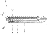
- the heater 1 includes a ceramic body 2, a heating resistor 3 embedded in the ceramic body 2, and leads 4 connected to the heating resistor 3 and drawn to the surface of the ceramic body 2. I have.
- the ceramic body 2 in the heater 1 is formed in a rod shape having a longitudinal direction, for example.
- a heating resistor 3 and leads 4 are embedded in the ceramic body 2.
- the ceramic body 2 has ceramics. Thereby, it becomes possible to provide the heater 1 with high reliability at the time of rapid temperature rise.
- the ceramic include electrically insulating ceramics such as oxide ceramics, nitride ceramics, and carbide ceramics.
- the ceramic body 2 may include silicon nitride ceramics. This is because silicon nitride ceramics is superior in terms of strength, toughness, insulating properties, and heat resistance.
- the ceramic body 2 having a silicon nitride ceramic is, for example, 3 to 12% by mass of a rare earth such as Y 2 O 3 , Yb 2 O 3 or Er 2 O 3 as a sintering aid with respect to silicon nitride as a main component.
- the length of the ceramic body 2 is set to 20 to 50 mm, for example, and the diameter of the ceramic body 2 is set to 3 to 5 mm, for example.
- the ceramic body 2 can be prepared by mixing the MoSiO 2 or WSi 2, etc., may be dispersed.
- the thermal expansion coefficient of the silicon nitride ceramic that is the base material can be brought close to the thermal expansion coefficient of the heating resistor 3, and the durability of the heater 1 can be improved.
- the heating resistor 3 is provided inside the ceramic body 2.
- the heating resistor 3 is provided on the tip side (one end side) of the ceramic body 2.
- the heating resistor 3 is a member that generates heat when an electric current flows.
- the heating resistor 3 includes a straight portion 32 extending along the longitudinal direction of the ceramic body 2 and a folded portion 30 that connects them.
- a material for forming the heating resistor 3 a material mainly composed of carbide, nitride, silicide or the like such as W, Mo or Ti can be used.
- tungsten carbide (WC) is the heating resistor 3 among the above materials in that the difference in coefficient of thermal expansion from the ceramic body 2 is small and the heat resistance is high. It is excellent as a material.
- the heating resistor 3 is mainly composed of WC of an inorganic conductor, and the content of silicon nitride added thereto is 20% by mass or more. Good.
- the conductor component that becomes the heating resistor 3 has a larger coefficient of thermal expansion than that of silicon nitride, and therefore is usually in a state where tensile stress is applied.
- the thermal expansion coefficient of the heating resistor 3 can be brought close to the thermal expansion coefficient of the ceramic body 2, so that the heater 1 is heated and cooled. The stress due to the difference in thermal expansion coefficient at the time can be relaxed.
- the content of silicon nitride contained in the heating resistor 3 when the content of silicon nitride contained in the heating resistor 3 is 40% by mass or less, the variation in the resistance value of the heating resistor 3 can be reduced. Therefore, the content of silicon nitride contained in the heating resistor 3 may be 20 to 40% by mass.
- the content of silicon nitride is preferably 25 to 35% by mass.
- 4 to 12% by mass of boron nitride can be added instead of silicon nitride.
- the heating resistor 3 can have a total length of 3 to 15 mm and a cross-sectional area of 0.15 to 0.8 mm 2 .
- the lead 4 is a member for electrically connecting the heating resistor 3 and an external power source.
- the lead 4 is connected to the heating resistor 3 and pulled out to the surface of the ceramic body 2.
- leads 4 are joined to both ends of the heating resistor 3.
- One lead 4 has one end connected to one end of the heating resistor 3 and the other end closer to the rear end of the ceramic body 2.
- the other lead 4 has one end connected to the other end of the heating resistor 3 and the other end led from the rear end of the ceramic body 2.
- the lead 4 is formed using the same material as the heating resistor 3, for example.
- the lead 4 has, for example, a WC.
- the lead 4 has a lower resistance per unit length by making the cross-sectional area larger than that of the heating resistor 3 or by making the content of the forming material of the ceramic body 2 smaller than that of the heating resistor 3. ing.
- the lead 4 may be mainly composed of WC, which is an inorganic conductor, and silicon nitride may be added thereto so that the content is 15 mass% or more. As the content of silicon nitride increases, the thermal expansion coefficient of the lead 4 can be made closer to the thermal expansion coefficient of silicon nitride constituting the ceramic body 2.
- the silicon nitride content may be 15 to 40% by mass.
- the silicon nitride content may be 20 to 35% by mass.
- a rod-shaped ceramic body 2 and a heating resistor 3 provided inside the ceramic body 2 are provided.
- the folded-back portion 30 has a linear protrusion 31 extending over the entire direction in which the folded-back portion 30 is folded back.
- the protrusion 31 protrudes outward and extends along the entire folded portion 30 along the folded portion 30.
- the amount of heat instantaneously trapped in the heating resistor 3 can be reduced, so that the thermal stress between the heating resistor 3 and the ceramic body 2 can be reduced. Therefore, the possibility that cracks may occur in the heating resistor 3 can be reduced. As a result, the long-term reliability of the heater 1 can be improved.
- the protrusion 31 may be located on the outermost periphery of the folded portion 30.
- the cross-sectional shape of the folded portion 30 is an elliptical shape.
- the folding unit 30 is folded on a virtual plane.
- the cross-sectional shape of the folded portion 30 has a long axis in a direction perpendicular to a virtual plane where the folded portion 30 is folded.
- the protrusion 31 is located on the extension line of the short axis in the elliptical shape.
- the shape of the protrusion 31 is a triangle, but is not limited thereto.
- the shape of the protrusion 31 may be, for example, a semicircular shape or a semi-elliptical shape, and various shapes can be used.
- the length (height) of the protrusion 31 in the protruding direction can be set to 5 to 30 ⁇ m.
- the shape of the tip of the protrusion 31 may be a smooth curved shape. Thereby, the possibility that a crack starting from the contact portion with the protrusion 31 is generated in the ceramic body 2 is reduced.
- the heating resistor 3 may have a folded portion 30 and a straight portion 32 continuous with the folded portion 30, and the protrusion 31 may extend to the straight portion 32. Thereby, heat can be more easily transmitted from the heating resistor 3 to the ceramic body 2. Thereby, it can further reduce that heat is trapped in the heating resistor 3.
- the end portion of the projection 31 is positioned not on the folded portion 30 but on the straight portion 32. Since the heat generating resistor 3 having the folded portion 30 tends to generate heat around the folded portion 30, if the end of the projection 31 is located in the middle of the folded portion 30, the heating resistor 3 is large at the end of the projection 31. Concentration of thermal stress may occur. As shown in FIG. 4, by keeping the end portion of the protrusion 31 at the straight portion 32, the possibility of a large concentration of thermal stress at the end portion of the protrusion 31 can be reduced.
- the heating resistor 3 may have a linear second protrusion 33 that extends over the entire direction in the direction of folding back to the inner periphery of the folded portion 30. Thereby, heat can be more easily transmitted from the heating resistor 3 to the ceramic body 2.
- the shape of the second protrusion 33 may be, for example, a semicircular shape or a semi-elliptical shape, and various shapes can be used.
- the length (height) in the protruding direction of the second protrusion 33 can be set to 5 to 30 ⁇ m.
- the shape of the tip of the second protrusion 33 may be a smooth curved shape. Thereby, the possibility that a crack starting from the contact portion with the second protrusion 33 is generated in the ceramic body 2 is reduced.
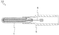
- the glow plug 10 includes the above-described heater 1 and a cylindrical metal tube 5 attached so as to cover the rear end side (the other end side) of the heater 1.
- an electrode fitting 6 that is disposed inside the metal tube 5 and is attached to the rear end of the heater 1 is provided. According to the glow plug 10, since the heater 1 described above is used, durability is improved.
- the metal cylinder 5 is a member for holding the ceramic body 2.
- the metal cylinder 5 is a cylindrical member and is attached so as to surround the rear end side of the ceramic body 2. That is, the rod-shaped ceramic body 2 is inserted inside the cylindrical metal tube 5.
- the metal cylinder 5 is provided on the side surface on the rear end side of the ceramic body 2 and is electrically connected to a portion where the lead 4 is exposed.
- the metal cylinder 5 includes, for example, stainless steel or iron (Fe) -nickel (Ni) -cobalt (Co) alloy.
- the metal cylinder 5 and the ceramic body 2 are joined by a brazing material.
- the brazing material is provided between the metal cylinder 5 and the ceramic body 2 so as to surround the rear end side of the ceramic body 2. By providing this brazing material, the metal cylinder 5 and the lead 4 are electrically connected.
- brazing material silver (Ag) -copper (Cu) brazing, Ag brazing, Cu brazing or the like containing 5 to 20% by mass of a glass component can be used. Since the glass component has good wettability with the ceramic of the ceramic body 2 and has a large coefficient of friction, the bonding strength between the brazing material and the ceramic body 2 or the bonding strength between the brazing material and the metal cylinder 5 can be improved.
- the electrode fitting 6 is located inside the metal cylinder 5 and attached to the rear end of the ceramic body 2 so as to be electrically connected to the lead 4.
- Various types of electrode fittings 6 can be used. However, in the example shown in FIG. 9, the cap part attached to cover the rear end of the ceramic body 2 including the lead 4 and the external connection electrode are electrically connected. It is the structure by which the coil-shaped part connected electrically is connected by the linear part.
- the electrode fitting 6 is held away from the inner peripheral surface of the metal cylinder 5 so as not to cause a short circuit with the metal cylinder 5.
- the electrode fitting 6 is a metal wire having a coil-shaped portion provided for stress relaxation in connection with an external power source.
- the electrode fitting 6 is electrically connected to the lead 4 and is electrically connected to an external power source.
- a current can be passed through the heating resistor 3 via the metal cylinder 5 and the electrode fitting 6.
- the electrode fitting 6 has nickel or stainless steel, for example.
- the heater 1 can be formed by, for example, an injection molding method using a die having the shape of the heating resistor 3, the lead 4, and the ceramic body 2 configured as described above.
- a rod-shaped ceramic body 2 and a heating resistor 3 provided inside the ceramic body 3 are provided.
- the heating resistor 3 includes a folded portion 30 and a folded portion.
- heat can be easily dispersed from the linear stepped portion 34 to the ceramic body 2.
- Can do As a result, the amount of heat instantaneously trapped in the heating resistor 3 can be reduced, so that the thermal stress between the heating resistor 3 and the ceramic body 2 can be reduced. Therefore, the possibility that cracks may occur in the heating resistor 3 can be reduced. As a result, the long-term reliability of the heater 1 can be improved.
- the stepped portion 34 may be located on the outermost periphery of the turned-up portion 30. Thereby, since heat can be easily dispersed to the outer peripheral side of the ceramic body 2, the amount of heat instantaneously trapped in the heating resistor 3 can be further reduced.
- the heating resistor 3 may have a linear second step portion 35 extending over the entire direction of folding back to the inner periphery of the folded portion 30. Thereby, heat can be more easily transferred from the heating resistor 3 to the ceramic body 2, so that it is possible to further reduce heat from being accumulated in the heating resistor 3.
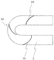
- the heating resistor 3 may further include a linear third protrusion 36 extending so as to straddle the inner periphery and the outer periphery.
- the third protrusion 36 since the third protrusion 36 is focused, the protrusion 31 or the stepped portion 34 is omitted.
- the third protrusion 36 By providing the third protrusion 36, it is possible to more easily transfer heat from the heating resistor 3 to the ceramic body 2.
- the third protrusion 36 extends obliquely with respect to the direction in which the folded portion 30 is folded back. As a result, heat can be easily dispersed from the inner peripheral side to the outer peripheral side in a wider range of the ceramic body 2, so that the amount of heat instantaneously trapped in the heating resistor 3 at the time of rapid temperature rise can be further reduced.
- the third protrusions 36 may extend obliquely with respect to the folding direction, or may extend in a direction perpendicular to the folding direction. When extending in a direction perpendicular to the folding direction, the third protrusion 36 may be provided over the entire circumference of the folding part 30. In other words, the third protrusion 36 may be annular and may extend over the entire circumference of the folded portion 30.
- Heater 2 Ceramic body 3: Heating resistor 30: Folded portion 31: Protrusion 32: Linear portion 33: Second protrusion 34: Step portion 35: Second step portion 36: Third protrusion 4: Lead 5: Metal cylinder 6: Electrode fitting 10: Glow plug
Landscapes
- Engineering & Computer Science (AREA)
- Chemical & Material Sciences (AREA)
- Combustion & Propulsion (AREA)
- Mechanical Engineering (AREA)
- General Engineering & Computer Science (AREA)
- Ceramic Engineering (AREA)
- Resistance Heating (AREA)
Abstract
本開示のヒータは、棒状のセラミック体と、該セラミック体の内部に設けられた発熱抵抗体とを備えており、該発熱抵抗体は、折返し部を有するとともに、該折返し部の外周に折返す方向の全体にわたって伸びる線状の突起を有する。
Description
本開示は、例えば燃焼式車載暖房装置における点火用もしくは炎検知用のヒータ、石油ファンヒータ等の各種燃焼機器の点火用のヒータ、ディーゼルエンジンのグロープラグ用のヒータ、酸素センサ等の各種センサ用のヒータまたは測定機器の加熱用のヒータ等に利用されるヒータおよびこれを備えたグロープラグに関するものである。
ヒータとして、例えば、特開2007-240080号公報(以下、特許文献1という)に記載のセラミックヒータが知られている。特許文献1に記載のセラミックヒータは、棒状でセラミック製の基体とこの基体中に埋設された発熱素子とを備えている。発熱素子は、軸線方向に延びる一対の棒状の導電部を有しており、この導電部を軸線方向に垂直な断面で見たときの形状が円形状である。
本開示の一態様のヒータは、棒状のセラミック体と、該セラミック体の内部に設けられた発熱抵抗体とを備えており、該発熱抵抗体は、折返し部を有するとともに、該折返し部の外周に折返す方向の全体にわたって伸びる線状の突起を有する。
図1に示すように、ヒータ1は、セラミック体2と、セラミック体2に埋設された発熱抵抗体3と、発熱抵抗体3に接続されてセラミック体2の表面に引き出されたリード4とを備えている。
ヒータ1におけるセラミック体2は、例えば長手方向を有する棒状に形成されたものである。このセラミック体2には発熱抵抗体3およびリード4が埋設されている。ここで、セラミック体2はセラミックスを有している。これにより急速昇温時の信頼性が高いヒータ1を提供することが可能になる。セラミックスとしては、酸化物セラミックス、窒化物セラミックスまたは炭化物セラミックス等の電気的に絶縁性を有するセラミックスが挙げられる。特に、セラミック体2は、窒化珪素質セラミックスを有していてもよい。窒化珪素質セラミックスは、主成分である窒化珪素が強度、靱性、絶縁性および耐熱性の観点で優れているからである。窒化珪素質セラミックスを有するセラミック体2は、例えば、主成分の窒化珪素に対して、焼結助剤として3~12質量%のY2O3、Yb2O3またはEr2O3等の希土類元素酸化物、0.5~3質量%のAl2O3および焼結体に含まれるSiO2量が1.5~5質量%となるようにSiO2を混合し、所定の形状に成形し、その後、1650~1780℃でホットプレス焼成することによって得ることができる。セラミック体2の長さは、例えば20~50mmに設定され、セラミック体2の直径は例えば3~5mmに設定される。
なお、セラミック体2として窒化珪素質セラミックスを有するものを用いる場合は、MoSiO2またはWSi2等を混合し、分散させてもよい。この場合には、母材である窒化珪素質セラミックスの熱膨張率を発熱抵抗体3の熱膨張率に近付けることができ、ヒータ1の耐久性を向上させることができる。
発熱抵抗体3は、セラミック体2の内部に設けられている。発熱抵抗体3はセラミック体2の先端側(一端側)に設けられている。発熱抵抗体3は、電流を流すことによって発熱する部材である。発熱抵抗体3は、セラミック体2の長手方向に沿って伸びる直線部32と、これらを連結する折返し部30とを有している。発熱抵抗体3の形成材料としては、W,MoまたはTiなどの炭化物、窒化物または珪化物などを主成分とするものを使用することができる。セラミック体2が窒化珪素質セラミックスを有する場合は、セラミック体2との熱膨張率の差が小さい点および高い耐熱性を有する点で、上記の材料の中でも炭化タングステン(WC)が発熱抵抗体3の材料として優れている。
さらに、セラミック体2が窒化珪素質セラミックスを有する場合は、発熱抵抗体3は、無機導電体のWCを主成分とし、これに添加される窒化珪素の含有率が20質量%以上であってもよい。例えば、窒化珪素質セラミックスを有するセラミック体2中において、発熱抵抗体3となる導体成分は窒化珪素と比較して熱膨張率が大きいため、通常は引張応力がかかった状態にある。これに対して、発熱抵抗体3中に窒化珪素を添加することにより、発熱抵抗体3の熱膨張率をセラミック体2の熱膨張率に近付けることができるので、ヒータ1の昇温時および降温時の熱膨張率の差による応力を緩和することができる。
また、発熱抵抗体3に含まれる窒化珪素の含有量が40質量%以下であるときには、発熱抵抗体3の抵抗値のばらつきを小さくさせることができる。従って、発熱抵抗体3に含まれる窒化珪素の含有量は20~40質量%であってもよい。また、窒化珪素の含有量は25~35質量%がよい。また、発熱抵抗体3への同様の添加物として、窒化珪素の代わりに窒化硼素を4~12質量%添加することもできる。発熱抵抗体3は全長を3~15mm、断面積を0.15~0.8mm2に設定することができる。
リード4は、発熱抵抗体3と外部の電源とを電気的に接続するための部材である。リード4は、発熱抵抗体3に接続されるとともにセラミック体2の表面に引き出されている。具体的には、発熱抵抗体3の両端部にそれぞれリード4が接合されていて、一方のリード4は、一端が発熱抵抗体3の一端に接続され、他端がセラミック体2の後端寄りの側面から導出され、他方のリード4は、一端が発熱抵抗体3の他端に接続され、他端がセラミック体2の後端部から導出されている。
このリード4は、例えば、発熱抵抗体3と同様の材料を用いて形成される。リード4は、例えば、WCを有している。リード4は、発熱抵抗体3よりも断面積を大きくしたり、セラミック体2の形成材料の含有量を発熱抵抗体3よりも少なくしたりすることによって、単位長さ当たりの抵抗値が低くなっている。また、リード4は無機導電体であるWCを主成分とし、これに窒化珪素を含有量が15質量%以上となるように添加してもよい。窒化珪素の含有量が増すにつれて、リード4の熱膨張率を、セラミック体2を構成する窒化珪素の熱膨張率に近付けることができる。また、窒化珪素の含有量が40質量%以下であるときには、リード4の抵抗値が低くなるとともに安定する。従って、窒化珪素の含有量は15~40質量%であってもよい。また、窒化珪素の含有量は20~35質量%としてもよい。
ここで、本実施形態のヒータ1においては、図1に示すように、棒状のセラミック体2と、セラミック体2の内部に設けられた発熱抵抗体3とを備えており、発熱抵抗体3は、折返し部30を有するとともに、折返し部30の外周に折返す方向の全体にわたって伸びる線状の突起31を有している。突起31は外側に突出するとともに折返し部30に沿って折返し部30の全体に沿って伸びている。これにより、発熱抵抗体3の折返し部30の外周に折返す方向の全体にわたって伸びる線状の突起31を有することによって、線状の突起31からセラミック体2に熱を分散しやすくすることができる。これにより、発熱抵抗体3に瞬間的にこもる熱の量を減らすことができるので、発熱抵抗体3とセラミック体2との間の熱応力を低減することができる。そのため、発熱抵抗体3にクラックが生じるおそれを低減できる。その結果、ヒータ1の長期信頼性を向上できる。
また、図2に示すように、突起31は、折返し部30の最外周に位置していてもよい。これによりセラミック体2のうちより外周側に熱を分散させやすくすることができるので、発熱抵抗体3に瞬間的にこもる熱の量をさらに減らすことができる。図2に示すヒータ1においては、折返し部30の断面形状が楕円形状である。折返し部30は、仮想平面上で折返している。折返し部30の断面形状は折返し部30が折り返す仮想平面に対して垂直な方向に長軸を有している。突起31は楕円形状のうち短軸の延長線上に位置している。
図2においては突起31の形状は三角形状であるが、これに限られない。突起31の形状としては、例えば、半円状であってもよいし、半楕円状であってもよく、様々な形を用いることができる。突起31は、例えば、突き出る方向の長さ(高さ)を5~30μmに設定できる。
また、図3に示すように、突起31の伸びる方向に対して垂直な断面を見たときに、突起31の先端の形状が滑らかな曲線形状であってもよい。これにより、セラミック体2に突起31との接触部分を起点とするクラックが生じるおそれを低減でいる。
また、図4に示すように、発熱抵抗体3は、折返し部30および折返し部30と連続した直線部32を有するとともに、突起31が直線部32にまで伸びていてもよい。これにより、発熱抵抗体3からセラミック体2に対してさらに熱を伝えやすくできる。これにより、発熱抵抗体3に熱がこもることをさらに低減できる。
また、突起31が折返し部30から直線部32にまで連続的に形成されていることによって、突起31の端部が折返し部30ではなく直線部32に位置することになる。折返し部30を有する発熱抵抗体3は、折返し部30を中心に熱が篭る傾向にあるため、折返し部30の途中に突起31の端部が位置してしまうと、突起31の端部において大きな熱応力の集中が生じるおそれがある。図4に示すように、突起31の端部を直線部32に位置させておくことによって、突起31の端部において大きな熱応力の集中が生じるおそれを低減できる。
また、図5に示すように、発熱抵抗体3は、折返し部30の内周に折返す方向の全体にわたって伸びる線状の第2突起33を有していてもよい。これにより、発熱抵抗体3からセラミック体2に対してさらに熱を伝えやすくすることができる。第2突起33の形状としては、例えば、半円状であってもよいし、半楕円状であってもよく、様々な形を用いることができる。第2突起33は、例えば、突き出る方向の長さ(高さ)を5~30μmに設定できる。第2突起33の伸びる方向に対して垂直な断面を見たときに、第2突起33の先端の形状が滑らかな曲線形状であってもよい。これにより、セラミック体2に第2突起33との接触部分を起点とするクラックが生じるおそれを低減でいる。
図6に示すように、グロープラグ10は、上述のヒータ1と、ヒータ1の後端側(他端側)を覆うように取り付けられた筒状の金属筒5とを備えている。また、金属筒5の内側に配置されてヒータ1の後端に取り付けられた電極金具6を備えている。グロープラグ10によれば、上述のヒータ1を使用していることから、耐久性が向上している。
金属筒5は、セラミック体2を保持するための部材である。金属筒5は、筒状の部材であって、セラミック体2の後端側を囲むように取り付けられている。すなわち、筒状の金属筒5の内側に棒状のセラミック体2が挿入されている。金属筒5は、セラミック体2の後端側の側面に設けられてリード4が露出している部分に電気的に接続されている。金属筒5は、例えば、ステンレスまたは鉄(Fe)-ニッケル(Ni)-コバルト(Co)合金を有する。
金属筒5とセラミック体2とは、ろう材によって接合されている。ろう材は、金属筒5とセラミック体2との間にセラミック体2の後端側を囲むように設けられている。このろう材が設けられていることによって、金属筒5とリード4とが電気的に接続されている。
ろう材としては、ガラス成分を5~20質量%含んだ銀(Ag)-銅(Cu)ろう、AgろうまたはCuろう等を用いることができる。ガラス成分はセラミック体2のセラミックスとの濡れ性が良く、摩擦係数が大きいために、ろう材とセラミック体2との接合強度またはろう材と金属筒5との接合強度を向上させることができる。
電極金具6は、金属筒5の内側に位置してセラミック体2の後端にリード4に電気的に接続するように取り付けられている。電極金具6は、種々の形態のものを用いることができるが、図9に示す例では、セラミック体2の後端にリード4を含んで被さるように取り付けられるキャップ部と外部の接続電極に電気的に接続されるコイル状部とが線状部で接続された構成である。この電極金具6は、金属筒5との間で短絡が生じないように金属筒5の内周面から離れて保持されている。
電極金具6は、外部の電源との接続における応力緩和のために設けられたコイル状部を有する金属線である。電極金具6は、リード4に電気的に接続されるとともに、外部の電源と電気的に接続される。外部の電源によって金属筒5と電極金具6との間に電圧を加えることによって、金属筒5および電極金具6を介して発熱抵抗体3に電流を流すことができる。電極金具6は、例えばニッケルまたはステンレスを有している。ヒータ1は、例えば、上記構成の発熱抵抗体3、リード4およびセラミック体2の形状の金型を用いた射出成形法等によって形成することができる。
また、図7に示すように、棒状のセラミック体2と、セラミック体3の内部に設けられた発熱抵抗体3とを備えており、発熱抵抗体3は、折返し部30を有するとともに、折返し部30の外周に折返す方向の全体にわたって伸びる線状の段差部34を有していてもよい。これにより、発熱抵抗体3の折返し部30の外周に折返す方向の全体にわたって伸びる線状の段差部34を有することによって、線状の段差部34からセラミック体2に熱を分散しやすくすることができる。これにより、発熱抵抗体3に瞬間的にこもる熱の量を減らすことができるので、発熱抵抗体3とセラミック体2との間の熱応力を低減することができる。そのため、発熱抵抗体3にクラックが生じるおそれを低減できる。その結果、ヒータ1の長期信頼性を向上できる。
また、図7に示すように、段差部34は、折返し部30の最外周に位置していてもよい。これにより、セラミック体2のうちより外周側に熱を分散させやすくすることができるので、発熱抵抗体3に瞬間的にこもる熱の量をさらに減らすことができる。
また、発熱抵抗体3は、折返し部30の内周に折り返す方向の全体にわたって伸びる線状の第2段差部35を有していてもよい。これにより、発熱抵抗体3からセラミック体2に対してさらに熱を伝えやすくできるので、発熱抵抗体3に熱がこもることをさらに低減できる。
また、図8に示すように、発熱抵抗体3は、内周と外周とを跨るように伸びる線状の第3突起36をさらに有していてもよい。なお、図8においては、第3突起36に着目していることから、突起31または段差部34は省略している。第3突起36が設けられていることによって、発熱抵抗体3からセラミック体2に対してさらに熱を伝えやすくすることができる。
図8において、第3突起36は折返し部30の折返す方向に対して斜めに伸びている。これにより、セラミック体2のより広範囲において内周側から外周側に熱を分散させやすくすることができるので、急速昇温時に発熱抵抗体3に瞬間的にこもる熱の量をさらに減らすことができる。なお、第3突起36は、折返す方向に対して斜めに伸びていてもよいし、折り返す方向に対して垂直な方向に伸びていてもよい。折り返す方向に対して垂直な方向に伸びる場合には、第3突起36が折返し部30の全周にわたって設けられていてもよい。言い換えると、第3突起36が環状になって、折返し部30の全周にわたっていてもよい。
1:ヒータ
2:セラミック体
3:発熱抵抗体
30:折返し部
31:突起
32:直線部
33:第2突起
34:段差部
35:第2段差部
36:第三突起
4:リード
5:金属筒
6:電極金具
10:グロープラグ
2:セラミック体
3:発熱抵抗体
30:折返し部
31:突起
32:直線部
33:第2突起
34:段差部
35:第2段差部
36:第三突起
4:リード
5:金属筒
6:電極金具
10:グロープラグ
Claims (10)
- 棒状のセラミック体と、該セラミック体の内部に設けられた発熱抵抗体とを備えており、該発熱抵抗体は、折返し部を有するとともに、該折返し部の外周に折返す方向の全体にわたって伸びる線状の突起を有するヒータ。
- 前記突起は、前記折返し部の最外周に位置する請求項1に記載のヒータ。
- 前記突起の伸びる方向に対して垂直な断面を見たときに、前記突起の先端の形状が滑らかな曲線形状である請求項1または請求項2に記載のヒータ。
- 前記発熱抵抗体は、前記折返し部および前記折返し部と連続した直線部を有するとともに、前記突起が前記直線部にまで伸びている請求項1乃至請求項3のいずれかに記載のヒータ。
- 前記発熱抵抗体は、前記折返し部の内周に折返す方向の全体にわたって伸びる線状の第2突起を有する請求項1乃至請求項4のいずれかに記載のヒータ。
- 棒状のセラミック体と、該セラミック体の内部に設けられた発熱抵抗体とを備えており、該発熱抵抗体は、折返し部を有するとともに、該折返し部の外周に折返す方向の全体にわたって伸びる線状の段差部を有するヒータ。
- 前記段差部は、前記折返し部の最外周に位置する請求項6に記載のヒータ。
- 前記発熱抵抗体は、前記折返し部の内周に折り返す方向の全体にわたって伸びる線状の第2段差部を有する請求項6または請求項7に記載のヒータ。
- 前記発熱抵抗体は、内周と外周とを跨るように伸びる線状の第3突起をさらに有する請求項1乃至請求項8のいずれかに記載のヒータ。
- 請求項1乃至請求項9のいずれかに記載のヒータであって前記発熱抵抗体が前記セラミック体の一端側に位置しているヒータと、前記セラミック体の他端側を覆うように取り付けられた金属筒とを備えたグロープラグ。
Priority Applications (2)
| Application Number | Priority Date | Filing Date | Title |
|---|---|---|---|
| EP17799141.1A EP3461228B1 (en) | 2016-05-17 | 2017-04-25 | Heater and glow plug equipped with same |
| JP2018518188A JP6725653B2 (ja) | 2016-05-17 | 2017-04-25 | ヒータおよびこれを備えたグロープラグ |
Applications Claiming Priority (2)
| Application Number | Priority Date | Filing Date | Title |
|---|---|---|---|
| JP2016-098489 | 2016-05-17 | ||
| JP2016098489 | 2016-05-17 |
Publications (1)
| Publication Number | Publication Date |
|---|---|
| WO2017199711A1 true WO2017199711A1 (ja) | 2017-11-23 |
Family
ID=60325023
Family Applications (1)
| Application Number | Title | Priority Date | Filing Date |
|---|---|---|---|
| PCT/JP2017/016347 Ceased WO2017199711A1 (ja) | 2016-05-17 | 2017-04-25 | ヒータおよびこれを備えたグロープラグ |
Country Status (3)
| Country | Link |
|---|---|
| EP (1) | EP3461228B1 (ja) |
| JP (1) | JP6725653B2 (ja) |
| WO (1) | WO2017199711A1 (ja) |
Cited By (1)
| Publication number | Priority date | Publication date | Assignee | Title |
|---|---|---|---|---|
| CN117249031A (zh) * | 2023-11-01 | 2023-12-19 | 上海夏雪科技有限公司 | 电热塞及内燃机 |
Citations (4)
| Publication number | Priority date | Publication date | Assignee | Title |
|---|---|---|---|---|
| JP2010108606A (ja) * | 2008-10-28 | 2010-05-13 | Kyocera Corp | セラミックヒータ |
| WO2011065366A1 (ja) * | 2009-11-27 | 2011-06-03 | 京セラ株式会社 | セラミックヒータ |
| JP2015103469A (ja) * | 2013-11-27 | 2015-06-04 | 日本特殊陶業株式会社 | セラミックヒータおよびグロープラグ |
| JP2015103470A (ja) * | 2013-11-27 | 2015-06-04 | 日本特殊陶業株式会社 | セラミックヒータおよびグロープラグ |
Family Cites Families (4)
| Publication number | Priority date | Publication date | Assignee | Title |
|---|---|---|---|---|
| WO2008123296A1 (ja) * | 2007-03-29 | 2008-10-16 | Kyocera Corporation | セラミックヒータとその金型 |
| JP2014219107A (ja) * | 2011-09-07 | 2014-11-20 | ボッシュ株式会社 | セラミックスヒータ型グロープラグ |
| JP5795029B2 (ja) * | 2013-07-09 | 2015-10-14 | 日本特殊陶業株式会社 | セラミックヒータ、グロープラグ、セラミックヒータの製造方法、および、グロープラグの製造方法 |
| WO2016103908A1 (ja) * | 2014-12-25 | 2016-06-30 | 京セラ株式会社 | ヒータおよびこれを備えたグロープラグ |
-
2017
- 2017-04-25 WO PCT/JP2017/016347 patent/WO2017199711A1/ja not_active Ceased
- 2017-04-25 EP EP17799141.1A patent/EP3461228B1/en active Active
- 2017-04-25 JP JP2018518188A patent/JP6725653B2/ja active Active
Patent Citations (4)
| Publication number | Priority date | Publication date | Assignee | Title |
|---|---|---|---|---|
| JP2010108606A (ja) * | 2008-10-28 | 2010-05-13 | Kyocera Corp | セラミックヒータ |
| WO2011065366A1 (ja) * | 2009-11-27 | 2011-06-03 | 京セラ株式会社 | セラミックヒータ |
| JP2015103469A (ja) * | 2013-11-27 | 2015-06-04 | 日本特殊陶業株式会社 | セラミックヒータおよびグロープラグ |
| JP2015103470A (ja) * | 2013-11-27 | 2015-06-04 | 日本特殊陶業株式会社 | セラミックヒータおよびグロープラグ |
Cited By (1)
| Publication number | Priority date | Publication date | Assignee | Title |
|---|---|---|---|---|
| CN117249031A (zh) * | 2023-11-01 | 2023-12-19 | 上海夏雪科技有限公司 | 电热塞及内燃机 |
Also Published As
| Publication number | Publication date |
|---|---|
| EP3461228B1 (en) | 2020-12-30 |
| EP3461228A1 (en) | 2019-03-27 |
| JPWO2017199711A1 (ja) | 2019-03-07 |
| EP3461228A4 (en) | 2020-01-01 |
| JP6725653B2 (ja) | 2020-07-22 |
Similar Documents
| Publication | Publication Date | Title |
|---|---|---|
| JP5436675B2 (ja) | ヒータおよびこれを備えたグロープラグ | |
| JP6023389B1 (ja) | ヒータおよびこれを備えたグロープラグ | |
| WO2012099232A1 (ja) | ヒータおよびこれを備えたグロープラグ | |
| JP6592103B2 (ja) | ヒータおよびこれを備えたグロープラグ | |
| JP6725653B2 (ja) | ヒータおよびこれを備えたグロープラグ | |
| CN102933903B (zh) | 加热器及具备该加热器的火花塞 | |
| JP6603321B2 (ja) | ヒータおよびこれを備えたグロープラグ | |
| JP6342653B2 (ja) | ヒータおよびこれを備えたグロープラグ | |
| JP6711697B2 (ja) | ヒータおよびこれを備えたグロープラグ | |
| JP7116237B2 (ja) | ヒータ | |
| JP6538467B2 (ja) | ヒータ及びグロープラグ | |
| JP7086205B2 (ja) | ヒータおよびこれを備えたグロープラグ | |
| JP6105464B2 (ja) | ヒータおよびこれを備えたグロープラグ | |
| JP5726311B2 (ja) | ヒータおよびこれを備えたグロープラグ | |
| JP6878116B2 (ja) | ヒータおよびこれを備えたグロープラグ | |
| JP6923425B2 (ja) | ヒータ | |
| JPWO2017135362A1 (ja) | ヒータおよびこれを備えたグロープラグ | |
| JPWO2018084083A1 (ja) | ヒータおよびこれを備えたグロープラグ |
Legal Events
| Date | Code | Title | Description |
|---|---|---|---|
| ENP | Entry into the national phase |
Ref document number: 2018518188 Country of ref document: JP Kind code of ref document: A |
|
| NENP | Non-entry into the national phase |
Ref country code: DE |
|
| 121 | Ep: the epo has been informed by wipo that ep was designated in this application |
Ref document number: 17799141 Country of ref document: EP Kind code of ref document: A1 |
|
| ENP | Entry into the national phase |
Ref document number: 2017799141 Country of ref document: EP Effective date: 20181217 |