WO2017199718A1 - 管状体のロック機構 - Google Patents
管状体のロック機構 Download PDFInfo
- Publication number
- WO2017199718A1 WO2017199718A1 PCT/JP2017/016572 JP2017016572W WO2017199718A1 WO 2017199718 A1 WO2017199718 A1 WO 2017199718A1 JP 2017016572 W JP2017016572 W JP 2017016572W WO 2017199718 A1 WO2017199718 A1 WO 2017199718A1
- Authority
- WO
- WIPO (PCT)
- Prior art keywords
- lock member
- housing
- tubular body
- bent
- diameter direction
- Prior art date
- Legal status (The legal status is an assumption and is not a legal conclusion. Google has not performed a legal analysis and makes no representation as to the accuracy of the status listed.)
- Ceased
Links
Images






Classifications
-
- F—MECHANICAL ENGINEERING; LIGHTING; HEATING; WEAPONS; BLASTING
- F16—ENGINEERING ELEMENTS AND UNITS; GENERAL MEASURES FOR PRODUCING AND MAINTAINING EFFECTIVE FUNCTIONING OF MACHINES OR INSTALLATIONS; THERMAL INSULATION IN GENERAL
- F16L—PIPES; JOINTS OR FITTINGS FOR PIPES; SUPPORTS FOR PIPES, CABLES OR PROTECTIVE TUBING; MEANS FOR THERMAL INSULATION IN GENERAL
- F16L37/00—Couplings of the quick-acting type
- F16L37/08—Couplings of the quick-acting type in which the connection between abutting or axially overlapping ends is maintained by locking members
- F16L37/084—Couplings of the quick-acting type in which the connection between abutting or axially overlapping ends is maintained by locking members combined with automatic locking
- F16L37/088—Couplings of the quick-acting type in which the connection between abutting or axially overlapping ends is maintained by locking members combined with automatic locking by means of a split elastic ring
- F16L37/0885—Couplings of the quick-acting type in which the connection between abutting or axially overlapping ends is maintained by locking members combined with automatic locking by means of a split elastic ring with access to the split elastic ring from a radial or tangential opening in the coupling
-
- F—MECHANICAL ENGINEERING; LIGHTING; HEATING; WEAPONS; BLASTING
- F16—ENGINEERING ELEMENTS AND UNITS; GENERAL MEASURES FOR PRODUCING AND MAINTAINING EFFECTIVE FUNCTIONING OF MACHINES OR INSTALLATIONS; THERMAL INSULATION IN GENERAL
- F16L—PIPES; JOINTS OR FITTINGS FOR PIPES; SUPPORTS FOR PIPES, CABLES OR PROTECTIVE TUBING; MEANS FOR THERMAL INSULATION IN GENERAL
- F16L37/00—Couplings of the quick-acting type
- F16L37/08—Couplings of the quick-acting type in which the connection between abutting or axially overlapping ends is maintained by locking members
- F16L37/084—Couplings of the quick-acting type in which the connection between abutting or axially overlapping ends is maintained by locking members combined with automatic locking
- F16L37/088—Couplings of the quick-acting type in which the connection between abutting or axially overlapping ends is maintained by locking members combined with automatic locking by means of a split elastic ring
-
- F—MECHANICAL ENGINEERING; LIGHTING; HEATING; WEAPONS; BLASTING
- F16—ENGINEERING ELEMENTS AND UNITS; GENERAL MEASURES FOR PRODUCING AND MAINTAINING EFFECTIVE FUNCTIONING OF MACHINES OR INSTALLATIONS; THERMAL INSULATION IN GENERAL
- F16B—DEVICES FOR FASTENING OR SECURING CONSTRUCTIONAL ELEMENTS OR MACHINE PARTS TOGETHER, e.g. NAILS, BOLTS, CIRCLIPS, CLAMPS, CLIPS OR WEDGES; JOINTS OR JOINTING
- F16B7/00—Connections of rods or tubes, e.g. of non-circular section, mutually, including resilient connections
- F16B7/04—Clamping or clipping connections
-
- F—MECHANICAL ENGINEERING; LIGHTING; HEATING; WEAPONS; BLASTING
- F16—ENGINEERING ELEMENTS AND UNITS; GENERAL MEASURES FOR PRODUCING AND MAINTAINING EFFECTIVE FUNCTIONING OF MACHINES OR INSTALLATIONS; THERMAL INSULATION IN GENERAL
- F16L—PIPES; JOINTS OR FITTINGS FOR PIPES; SUPPORTS FOR PIPES, CABLES OR PROTECTIVE TUBING; MEANS FOR THERMAL INSULATION IN GENERAL
- F16L37/00—Couplings of the quick-acting type
- F16L37/08—Couplings of the quick-acting type in which the connection between abutting or axially overlapping ends is maintained by locking members
- F16L37/084—Couplings of the quick-acting type in which the connection between abutting or axially overlapping ends is maintained by locking members combined with automatic locking
- F16L37/0841—Couplings of the quick-acting type in which the connection between abutting or axially overlapping ends is maintained by locking members combined with automatic locking by means of a transversally slidable locking member surrounding the tube
-
- F—MECHANICAL ENGINEERING; LIGHTING; HEATING; WEAPONS; BLASTING
- F16—ENGINEERING ELEMENTS AND UNITS; GENERAL MEASURES FOR PRODUCING AND MAINTAINING EFFECTIVE FUNCTIONING OF MACHINES OR INSTALLATIONS; THERMAL INSULATION IN GENERAL
- F16L—PIPES; JOINTS OR FITTINGS FOR PIPES; SUPPORTS FOR PIPES, CABLES OR PROTECTIVE TUBING; MEANS FOR THERMAL INSULATION IN GENERAL
- F16L37/00—Couplings of the quick-acting type
- F16L37/08—Couplings of the quick-acting type in which the connection between abutting or axially overlapping ends is maintained by locking members
- F16L37/084—Couplings of the quick-acting type in which the connection between abutting or axially overlapping ends is maintained by locking members combined with automatic locking
- F16L37/098—Couplings of the quick-acting type in which the connection between abutting or axially overlapping ends is maintained by locking members combined with automatic locking by means of flexible hooks
-
- F—MECHANICAL ENGINEERING; LIGHTING; HEATING; WEAPONS; BLASTING
- F16—ENGINEERING ELEMENTS AND UNITS; GENERAL MEASURES FOR PRODUCING AND MAINTAINING EFFECTIVE FUNCTIONING OF MACHINES OR INSTALLATIONS; THERMAL INSULATION IN GENERAL
- F16L—PIPES; JOINTS OR FITTINGS FOR PIPES; SUPPORTS FOR PIPES, CABLES OR PROTECTIVE TUBING; MEANS FOR THERMAL INSULATION IN GENERAL
- F16L37/00—Couplings of the quick-acting type
- F16L37/08—Couplings of the quick-acting type in which the connection between abutting or axially overlapping ends is maintained by locking members
- F16L37/12—Couplings of the quick-acting type in which the connection between abutting or axially overlapping ends is maintained by locking members using hooks, pawls, or other movable or insertable locking members
- F16L37/133—Couplings of the quick-acting type in which the connection between abutting or axially overlapping ends is maintained by locking members using hooks, pawls, or other movable or insertable locking members using flexible hooks
-
- F—MECHANICAL ENGINEERING; LIGHTING; HEATING; WEAPONS; BLASTING
- F16—ENGINEERING ELEMENTS AND UNITS; GENERAL MEASURES FOR PRODUCING AND MAINTAINING EFFECTIVE FUNCTIONING OF MACHINES OR INSTALLATIONS; THERMAL INSULATION IN GENERAL
- F16L—PIPES; JOINTS OR FITTINGS FOR PIPES; SUPPORTS FOR PIPES, CABLES OR PROTECTIVE TUBING; MEANS FOR THERMAL INSULATION IN GENERAL
- F16L37/00—Couplings of the quick-acting type
- F16L37/08—Couplings of the quick-acting type in which the connection between abutting or axially overlapping ends is maintained by locking members
- F16L37/12—Couplings of the quick-acting type in which the connection between abutting or axially overlapping ends is maintained by locking members using hooks, pawls, or other movable or insertable locking members
- F16L37/14—Joints secured by inserting between mating surfaces an element, e.g. a piece of wire, a pin, a chain
- F16L37/142—Joints secured by inserting between mating surfaces an element, e.g. a piece of wire, a pin, a chain where the securing element is inserted tangentially
- F16L37/144—Joints secured by inserting between mating surfaces an element, e.g. a piece of wire, a pin, a chain where the securing element is inserted tangentially the securing element being U-shaped
Definitions
- This invention relates to a tubular body locking mechanism.
- a pipe connector in which the wire is pulled upward and the wire moves in the outer diameter direction so that the pipe can be inserted or released. Yes.
- the wire is provided with a bent portion protruding into the connector through the slit of the connector.
- the present invention has been made in view of the problems of the above-described conventional techniques, and the object of the present invention is to reduce the operating force when inserting a tubular body such as a pipe and to connect the tubular bodies. The operability at the time can be improved.
- the tubular body locking mechanism according to the first aspect of the present invention is characterized by the following points.
- the locking mechanism of the tubular body has the following configuration.
- Housing The housing has a cylindrical shape in which a tubular body having an engaging portion is attached to at least one end.
- Lock member The lock member can engage and release the housing and the tubular body.
- the locking member is attached to the housing so as to be movable in the outer diameter direction by the tapered portion of the tubular body when the tubular body is inserted.
- the housing includes a slit formed to be engaged with the engaging portion of the tubular body attached to the housing, through which a bent portion provided in the distal end side of the lock member and bent in the inner diameter direction passes. Yes.
- a gap is provided between the bent portion and the end of the slit located on the opposite side of the front end side of the lock member so as not to contact at least during the movement of the lock member.
- the tubular body locking mechanism according to the second aspect of the present invention is characterized by the following points.
- the locking mechanism of the tubular body has the following configuration.
- Housing The housing has a cylindrical shape in which a tubular body having an engaging portion is attached to at least one end.
- Lock member The lock member can engage and release the housing and the tubular body.
- the lock member is attached to the housing so as to be movable in the outer diameter direction.
- the housing includes a slit formed to be engaged with the engaging portion of the tubular body attached to the housing, through which a bent portion provided in the distal end side of the lock member and bent in the inner diameter direction passes. Yes.
- the housing is provided with a guide part for expanding the bent part to the outside when the lock member moves in the outer diameter direction at least when unlocking.
- the guide portion is provided on the distal end side of the lock member rather than the end portion of the slit.
- the sliding slope may extend from the outer surface of the slidable housing toward the radially outer side.
- the lock member such as a wire
- the distal end side of the lock member can be widened on the sliding slope, so that the operability is good, and when moving in the inner diameter direction, the lock member is locked. Can be guided to.
- the distal end portion and the sliding slope may come into contact with each other during the movement.
- the movement at the start of movement of the lock member can be lightened, and the operability at the time of insertion and release of a tubular body such as a pipe is improved. can do. That is, when the distal end of the lock member starts moving, the operating force for bending the lock member in the outer diameter direction gradually increases.
- the distal end portion of the lock member is brought into contact with the running portion, there is an advantage that the operability can be improved without increasing the operation force at the start of movement.
- the lock member may be configured to be held by a holding portion provided on the sliding slope after movement.
- the lock member can be held with a simple configuration, that is, can be fixed at the release position.
- the bent portion includes a first bent portion and a second bent portion provided at opposing positions, and a third bent portion is provided between the first bent portion and the second bent portion. May be provided.
- a tubular body such as a pipe can be held at three points of the first bent portion, the second bent portion, and the third bent portion, and can be held firmly.
- the operation force when inserting a tubular body such as a pipe is reduced, and the operability when connecting the tubular bodies is reduced. Can be improved.
- the distal end side of the lock member is provided on the distal end side of the lock member such as a wire by moving the lock member in the outer diameter direction from the end portion of the slit. It can be opened relatively, the operation force at the time of unlocking can be reduced, and the operability at the time of releasing the connected state of the tubular body can be improved. That is, when the front end side of the lock member is opened, the operating force can be reduced as compared with the case where the middle of the length of the lock member is opened.
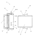
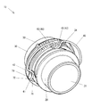
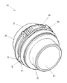
- FIG. 6 is a perspective view of a housing according to an embodiment of the present invention with a tubular body inserted and locked by a locking member according to an embodiment of the present invention.
- FIG. 4 is a side view of the housing corresponding to FIG. 3 in a locked state of the lock member.
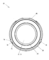
- FIG. 4 is a plan view of the housing corresponding to FIG. 3 in a locked state of the lock member.
- FIG. 4 is a right side view of the housing in a locked state of the lock member corresponding to FIG. 3.
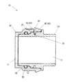
- FIG. 6 is a cross-sectional view taken along line AA in FIG. 5.
- FIG. 9 is a perspective view corresponding to FIG. 8 with a part of the housing cut away in a locked state of the lock member. It is the side view which notched a part of housing in the lock release state of a lock member.
- FIG. 11 is a side view corresponding to FIG. 10 in which a part of the housing is cut away in a locked state of the lock member.
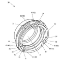
- FIG. 4 is a perspective view of the housing in the unlocked state of the lock member corresponding to FIG. 3.
- FIG. 6 is a side view of the housing corresponding to FIG. 4 in the unlocked state of the lock member.
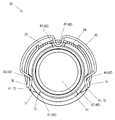
- FIG. 6 is a plan view of the housing in the unlocked state of the lock member corresponding to FIG.
- FIG. 7 is a right side view of the housing in the unlocked state of the lock member corresponding to FIG. 6. It is sectional drawing which follows the BB line of FIG. It is explanatory drawing for demonstrating the engagement state of the front-end
- FIGS. Lock mechanism 10
- reference numeral 10 denotes a locking mechanism for the tubular body 20
- the locking mechanism 10 can be used as, for example, a turbo duct of an automobile or a piping connector for an intercooler.
- a turbo duct of an automobile and a pipe of an intercooler have been exemplified, but the invention is not limited to this, and it can be used not only for a water system such as a radiator but also for an automobile, a train, a ship In addition to aircraft, it can also be used for residential equipment, agricultural irrigation, and industrial applications.
- the lock mechanism 10 includes the following parts when roughly classified. The following (1) to (4) will be described later.
- Tubular body 20 (2) Housing 30 (3) Lock member 40 (4) O-ring 50
- the parts of the lock mechanism 10 are not limited to the above (1) to (4), and for example, “(4) O-ring 50” may be omitted.
- the tubular body 20 is formed in a tubular or pipe shape and includes an engaging portion 26.
- the tubular body 20 is integrally formed of, for example, a thermoplastic synthetic resin having rigidity.
- the tubular body 20 has a hollow portion 21 penetrating left and right, and has a flange portion 22 projecting annularly in the outer diameter direction in the middle of the left and right lengths.
- the tubular body 20 is located on the left side with the flange portion 22 in between, facing the housing 30, and the insertion portion 23 that can be inserted into an opening 31 to be described later of the housing 30, on the opposite side, that is, on the right side.
- a connecting portion 24 for connecting a pipe or the like (not shown).
- the insertion part 23 has the following parts when roughly classified. The following (1) and (2) will be described later.
- (1) Taper 25 (2) Engagement part 26
- the insertion portion 23 is not limited to the above (1) and (2).
- the taper portion 25 abuts against the lock member 40 in the opening 31 when the insertion portion 23 is inserted into an opening 31 described later of the housing 30. This is for moving 40 in the outer diameter direction with respect to the housing 30, that is, for expanding the diameter.
- the taper portion 25 is raised in the shape of a truncated cone from the middle of the insertion portion 23 in the full length direction, and gradually increases in outer diameter toward the flange portion 22.
- the engaging portion 26 is located between the tapered portion 25 and the housing 30, and a bent portion 42, which will be described later, of the lock member 40 in the opening portion 31 of the housing 30. Is for locking the insertion part 23 of the tubular body 20.
- the engaging portion 26 is formed in a concave shape that is recessed in an annular shape, and the lock member 40 that has been expanded in diameter by the tapered portion 25 gets stuck by being reduced in diameter by the restoring force of the spring.
- the housing 30 has a cylindrical shape to which a tubular body 20 having an engaging portion 26 is attached at least at one end.
- the housing 30 is integrally formed of a rigid, for example, thermoplastic synthetic resin.
- the housing 30 has an opening 31 penetrating left and right in FIG. 2, and the inner diameter of the opening 31 is set to be larger than the outer diameter of the insertion portion 23 of the tubular body 20.
- a ring groove 32 that is recessed in an annular shape is provided in the opening 31, and an O-ring 50 described later is fitted into the ring groove 32.
- a pair of jig oblique grooves 33 and 34 are provided on the outer periphery of the housing 30.
- the pair of jig oblique grooves 33 and 34 are respectively located on both sides of a third slit 63 located above a slit 60 described later.
- Each of the jig oblique grooves 33 and 34 is inclined downward toward the third slit 63 side, and although not shown, a tip of a minus driver which is an example of a jig can be inserted obliquely.
- the tip of the inserted flathead screwdriver is inserted between the outer periphery of the housing 30 and the lock member 40. With the tip of the flathead screwdriver inserted, the lock member 40 can be lifted in the direction of the outer diameter of the housing 30 using the principle of the lever, whereby the lock state of the lock member 40 is released.
- the housing 30 is provided with the following parts as shown in FIGS. The following (1) and (2) will be described later.
- each part of the housing 30 is not limited to the above (1) and (2).
- the lock member 40 is capable of engaging and releasing the housing 30 and the tubular body 20. As shown in FIGS. 2 and 8 to 11, the locking member 40 is attached to the housing 30 so as to be movable in the outer diameter direction by the tapered portion 25 of the tubular body 20 when the tubular body 20 is inserted. .
- the lock member 40 is made of, for example, a metal wire or wire, and is formed by bending the wire into a generally C shape with the lower portion opened in FIGS. I have it.
- the lock member 40 has an approximately C-shaped inner diameter set to be equal to or smaller than the outer diameter of the housing 30 and is fitted into the outer periphery of the housing 30 from the outside by using the spring property, and tightens the outer periphery of the housing 30 by the elastic restoring force of the spring. ing.
- the lock member 40 may have a spring property by bending a metal plate instead of a metal wire or wire.
- the lock member 40 is provided with the following parts.
- the following (1) and (2) will be described later.
- each part of the lock member 40 is not limited to the above (1) and (2).
- the O-ring 50 As shown in FIG. 2, the O-ring 50 is fitted into a ring groove 32 provided in the opening 31 of the housing 30 and partially protrudes into the opening 31.
- the O-ring 50 is made of, for example, rubber, and elastically contacts the outer peripheral surface of the insertion portion 23 of the tubular body 20 inserted into the opening 31 as shown in FIGS. The space between the peripheral surface and the outer peripheral surface of the insertion portion 23 is sealed.
- one O-ring 50 is used, a plurality of O-rings 50 may be used.
- the distal end portion 41 of the lock member 40 is positioned at a pair of free ends that are substantially C-shaped and open at the bottom, that is, at the left and right lower end portions, respectively. As shown in FIGS. 8 and 9, the distal end portion 41 is bent in an approximately L shape from the circumferential direction of the housing 30 to the full length direction, and engages with a guide portion 70 described later of the housing 30.
- the bent portion 42 of the lock member 40 is a portion bent in the inner diameter direction, and is provided in a plurality of, for example, three locations.
- the bent portion 42 can pass through a later-described slit 60 penetrating into and out of the housing 30, and can protrude into the opening 31 of the housing 30, and in the protruded state, as shown in FIGS. It is formed to engage with the engaging portion 26 of the body 20.
- the bent portion 42 includes the following portions. Although the three bent portions 42 are illustrated as the first to third bent portions 43 to 45, the present invention is not limited to this, and the third bent portion 45 may be omitted, or two or four or more. It is good.
- (1) First and second bent portions 43 and 44 As shown in FIGS. 8 to 11, the first and second bent portions 43 and 44 are provided on the distal end side of the lock member 40, that is, on the distal end portion 41 side, and are bent in the inner diameter direction. The first and second bent portions 43 and 44 can pass through first and second slits 61 and 62, which will be described later, penetrating into and out of the housing 30, respectively, and can project into the opening 31 of the housing 30.
- the first and second bent portions 43 and 44 are bent substantially into a V shape or a mountain shape, are formed continuously on the upper side of the tip portion 41, and a total of two are provided in line symmetry on the left and right. .
- the first and second bent portions 43 and 44 are bent into a substantially V shape or mountain shape, the present invention is not limited to this, and may be bent into a substantially U shape, for example.
- the third bent portion 45 is provided between the first and second bent portions 43 and 44 and is bent in the inner diameter direction.
- the third bent portion 45 can pass through a later-described third slit 63 that penetrates into and out of the housing 30, and can protrude into the opening 31 of the housing 30, and in the protruded state, the third bent portion 45 is shown in FIGS. Thus, it is formed to engage with the engaging portion 26 of the tubular body 20.
- the third bent portion 45 is bent in a substantially U shape, and one third bent portion 45 is provided between the first and second bent portions 43 and 44, that is, on the upper side.
- the third bent portion 45 is bent into a substantially U shape, but is not limited thereto, and may be bent into a substantially V shape or a mountain shape, for example.
- the slit 60 passes through the first to third bent portions 43 to 45 of the lock member 40 and engages with the engaging portion 26 of the tubular body 20 attached to the housing 30. It was formed accordingly.
- a plurality of, for example, three slits 60 are formed along the circumferential direction of the housing 30 so as to penetrate from the outer periphery of the housing 30 toward the opening 31 in the form of grooves.
- the heel slit 60 includes the following parts. Although the following (1) to (4) are illustrated as the respective portions of the slit 60, the present invention is not limited to this.
- the first to third slits 61 to 63 are exemplified as the slit 60.
- the present invention is not limited to this, and the third bent portion 45 of the lock member 40 may be omitted, or two may be used.
- Four or more bent portions 42 of the member 40 may be provided and may be four or more.
- First slit 61 The first slit 61 is located on the left side in FIGS. 10 and 11, and the first bent portion 43 located in the same direction of the lock member 40 can pass therethrough.
- Second slit 62 The second slit 62 is located on the right side in FIGS. 10 and 11, and the second bent portion 44 located in the same direction of the lock member 40 can pass therethrough.
- Third slit 63 10 and 11, the third slit 63 is located at the upper center, and the third bent portion 45 located in the middle of the length of the lock member 40, that is, at the upper center, can pass therethrough.
- the gap portion 64 includes the bent portion 42 (the left and right first and second bent portions 43 and 44) of the lock member 40 and the distal end side of the lock member 40, that is, the distal end portion 41 side. Is positioned between the ends (upper end portions) of the slits 60 (left and right first and second slits 61 and 62) located on the opposite side of the lock member 40 so as not to contact at least during the movement of the lock member 40 It is to make. Specifically, the gap portion 64 is formed by extending the upper end portion of the first slit 61 toward the upper side in the circumferential direction of the housing 30 when taking one side as an example.
- the first bent portion 43 of the lock member 40 is reduced in diameter in the inner diameter direction, passes through the first slit 61, and protrudes into the opening 31 of the housing 30.
- FIG. 8 and FIG. 10 when moving to a state where the diameter is increased in the outer diameter direction, it moves in the gap 64 and does not contact the edge of the upper end of the first slit 61. For this reason, the frictional resistance can be eliminated and the operating force for expanding the diameter of the lock member 40 can be eliminated compared with the case of expanding the diameter in the outer diameter direction while contacting the edge of the upper end portion of the first slit 61. Can be reduced.
- the guide portion 70 has its bent portion 42, that is, the first and second bent portions 43, 44 at least when the lock member 40 moves in the outer diameter direction at the time of unlocking. It is for spreading outside.
- the guide part 70 is a front end side of the lock member 40 from the slit 60, that is, the first and second slits 61, 62, that is, the front end part 41 side, specifically, in the circumferential direction of the housing 30, A total of two are provided on the left and right sides.
- each guide portion 70 is engaged with a tip portion 41 bent into a substantially L shape of the lock member 40.
- the lock member 40 When the lock member 40 is reduced in diameter and expanded in diameter, It extends along the trajectory of the tip 41, that is, in the circumferential direction of the housing 30.
- Each guide portion 70 protrudes from the outer peripheral surface of the housing 30 in the outer diameter direction, and the side surface is formed in a two- and two-hump shape.
- the guide unit 70 is provided with the following units. Each part of the guide part 70 is not limited to the following (1) to (3).
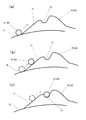
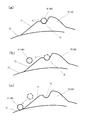
- (1) Sliding slope 71 As shown in FIG. 17, the sliding inclined surface 71 is moved in the inner diameter direction when the lock member 40 moves in the outer diameter direction with respect to the housing 30 or from the position after the movement in the outer diameter direction as shown in FIG. When moving to the right, the distal end portion 41 of the lock member 40 extends radially outward from the outer surface of the slidable housing 30.
- the sliding slope 71 is composed of a slope that reaches a small hump among the two large and small humps.
- the holding portion 72 is provided on the sliding inclined surface 71 after the distal end portion 41 of the lock member 40 is moved, and holds the distal end portion 41.
- the holding part 72 is formed in a concave shape between two large and small humps, and the front end part 41 of the lock member 40 is fitted therein.
- Run-up part 73 When the lock member 40 moves in the outer diameter direction with respect to the housing 30, the run-up portion 73 is arranged so that the tip 41 of the lock member 40 and the sliding slope 71 come into contact with each other as shown in FIG. To do.
- the running portion 73 is a portion that curves along the outer peripheral surface of the housing 30 and reaches the sliding slope 71.
- the tubular body 20 can be connected to the housing 30 by inserting the insertion portion 23 in accordance with the opening 31 of the housing 30 as shown in FIGS. That is, when the insertion portion 23 is inserted, the tapered portion 25 comes into contact with the first to third bent portions 43 to 45 protruding into the opening portion 31. For this reason, the first to third bent portions 43 to 45 are pushed by the tapered portion 25, and the lock member 40 is expanded in the outer diameter direction. At this time, the distal end portion 41 of the locking member 40 slides while contacting the running portion 73 of the housing 30 as shown in FIG. Or you may move in the state which floated without sliding the run-up part 73.
- the distal end portion 41 of the lock member 40 reaches the sliding slope 71 from the run-up portion 73 of the guide portion 70, and as shown in FIG. It slides while touching the moving slope 71 and climbs the sliding slope 71.
- the first to third bent portions 43 to 45 get over the tapered portion 25 and fall into the concave engaging portion 26.
- the lock member 40 is reduced in diameter in the inner diameter direction by the restoring force of the spring,
- the third bent parts 43 to 45 fit into the engaging part 26, and the insertion part 23 of the tubular body 20 cannot be removed from the opening part 31 of the housing 30, and is locked in a connected state.
- the diameter of the lock member 40 is reduced, the diameter of the lock member 40 is rapidly reduced in the inner diameter direction due to the restoring force of the spring. It strikes 71 and slides while contacting the sliding slope 71. Thereafter, the distal end portion 41 of the lock member 40 moves down the sliding slope 71 to the run-up portion 73 and slides while contacting the run-up portion 73.
- the tip 41 reaches the sliding slope 71 from the run-up portion 73 of the guide portion 70 as shown in FIGS. 17 (a) and 17 (b). It slides while touching and climbs the sliding slope 71.
- the tip end portion 41 gets over the sliding slope 71 and falls into the concave holding portion 72 as shown in FIG.
- the lock member 40 is reduced in diameter in the inner diameter direction by the restoring force of the spring, the distal end portion 41 of the lock member 40 is fitted into the holding portion 72, and the lock member 40 is locked by the guide portion 70.
- the lock member 40 is expanded in the outer diameter direction by sliding the tip portion 41 of the lock member 40 in contact with the sliding slope 71.
- the first to third bent portions 43 to 45 of the lock member 40 float from the engaging portion 26 of the tubular body 20, and the locked state between the tubular body 20 and the housing 30 is released.
- the first and second bent portions 43 and 44 are moved within the gap portions 64 of the first and second slits 61 and 62, so that there is no frictional resistance and an operation for expanding the diameter of the lock member 40. Power can be reduced.
- the first to third bent portions 43 to 45 of the lock member 40 float from the engaging portion 26 of the tubular body 20, the insertion portion 23 of the tubular body 20 can be extracted from the opening 31 of the housing 30. .
- the central portion of the raised lock member 40 may be pushed downward and the lock member 40 may be lowered.
- the lock member 40 is lowered, as shown in FIG. 18, the tip end portion 41 comes out of the holding portion 72 of the guide portion 70, and the lock state of the lock member 40 by the guide portion 70 is released.
- the diameter of the lock member 40 is gradually reduced in the inner diameter direction, and as shown in FIGS. 18 (b) and 18 (c), the distal end portion 41 descends the sliding slope 71 to the run-up portion 73. It slides in contact with the running part 73. Since the lock member 40 is reduced in diameter in the inner diameter direction, the first to third bent portions 43 to 45 pass through the first to second slits 61 to 63 of the housing 30, respectively, as shown in FIGS. Then, it projects again into the opening 31 of the housing 30, and the tubular body 20 is returned to a connectable state.
- Lock mechanism 20 Tubular body 21 Hollow part 22 Flange part 23 Insertion part 24 Connection part 25 Taper part 26 Engagement part 30 Housing 31 Opening part 32 Ring groove 33,34 Diagonal groove for jig 40 Lock member 41 Tip part 42 Bending part 43 1st bent part 44 2nd bent part 45 3rd bent part 50 O-ring 60 Slit 61 1st slit 62 2nd slit 63 3rd slit 64 Gap part 70 Guide part 71 Sliding slope 72 Holding part 73 Running part The entire contents of the specification, claims, drawings, and abstract of Japanese Patent Application No. 2016-101191 filed on May 20, 2016 are incorporated herein as the disclosure of the specification of the present invention. Is.
Landscapes
- Engineering & Computer Science (AREA)
- General Engineering & Computer Science (AREA)
- Mechanical Engineering (AREA)
- Quick-Acting Or Multi-Walled Pipe Joints (AREA)
- Mutual Connection Of Rods And Tubes (AREA)
Abstract
ロック部材は、管状体の挿入時に管状体のテーパー部によって、ハウジングに対して外径方向に移動可能に取り付いている。ハウジングは、ロック部材の先端側に設けられた内径方向に屈曲した屈曲部が通過し、ハウジングに装着された管状体の係合部と係合するべく形成されたスリットを備えている。屈曲部と、ロック部材の先端側とは逆方向側に位置するスリットの端部との間には、少なくともロック部材の移動中は当接しないようにする隙間部が設けられている。
Description
この発明は、管状体のロック機構に関する。
従来、パイプを挿入する際やパイプを解除する際は、ワイヤが上方に引き上がり、ワイヤが外径方向に移動することで、パイプの挿入又が解除が可能となるパイプのコネクタが知られている。具体的には、ワイヤには、コネクタのスリットを通してコネクタの内部に突出する屈曲部を設けてある。
しかし、上記した従来のコネクタでは、パイプのロック時やロック解除時に、ワイヤの屈曲部がスリットの端に当たったり、当該端に当たった状態で摺り動くため、摩擦抵抗等の要因で、プラグのロック時やロック解除時に必要とされる操作力が高くなり、操作し難いといった問題点があった。
そこで、本発明は、上記した従来の技術が有する問題点に鑑みてなされたものであり、その目的とするところは、パイプ等の管状体の挿入時の操作力を軽減し、管状体の連結時の操作性を向上することができるようにしたものである。
そこで、本発明は、上記した従来の技術が有する問題点に鑑みてなされたものであり、その目的とするところは、パイプ等の管状体の挿入時の操作力を軽減し、管状体の連結時の操作性を向上することができるようにしたものである。
本発明は、上記した目的を達成するためになされたものであり、本発明の第1態様による管状体のロック機構は、次の点を特徴とする。
第1に、管状体のロック機構は、次の構成からなる。
(1)ハウジング
ハウジングは、係合部を備えた管状体が少なくとも一端に装着される筒状のものである。
(2)ロック部材
ロック部材は、ハウジングと管状体とを係合及び解除可能なものである。
第1に、管状体のロック機構は、次の構成からなる。
(1)ハウジング
ハウジングは、係合部を備えた管状体が少なくとも一端に装着される筒状のものである。
(2)ロック部材
ロック部材は、ハウジングと管状体とを係合及び解除可能なものである。
第2に、ロック部材は、管状体の挿入時に管状体のテーパー部によって、ハウジングに対して外径方向に移動可能に取り付いている。
第3に、ハウジングは、ロック部材の先端側に設けられた内径方向に屈曲した屈曲部が通過し、ハウジングに装着された管状体の係合部と係合するべく形成されたスリットを備えている。
第3に、ハウジングは、ロック部材の先端側に設けられた内径方向に屈曲した屈曲部が通過し、ハウジングに装着された管状体の係合部と係合するべく形成されたスリットを備えている。
第4に、屈曲部と、ロック部材の先端側とは逆方向側に位置するスリットの端部との間には、少なくともロック部材の移動中は当接しないようにする隙間部が設けられている。
本発明の第2態様による管状体のロック機構は、次の点を特徴とする。
第1に、管状体のロック機構は、次の構成からなる。
(1)ハウジング
ハウジングは、係合部を備えた管状体が少なくとも一端に装着される筒状のものである。
(2)ロック部材
ロック部材は、ハウジングと管状体とを係合及び解除可能なものである。
第1に、管状体のロック機構は、次の構成からなる。
(1)ハウジング
ハウジングは、係合部を備えた管状体が少なくとも一端に装着される筒状のものである。
(2)ロック部材
ロック部材は、ハウジングと管状体とを係合及び解除可能なものである。
第2に、ロック部材は、ハウジングに対して外径方向に移動可能に取り付いている。
第3に、ハウジングは、ロック部材の先端側に設けられた内径方向に屈曲した屈曲部が通過し、ハウジングに装着された管状体の係合部と係合するべく形成されたスリットを備えている。
第3に、ハウジングは、ロック部材の先端側に設けられた内径方向に屈曲した屈曲部が通過し、ハウジングに装着された管状体の係合部と係合するべく形成されたスリットを備えている。
第4に、また、ハウジングは、少なくともロック解除時に、ロック部材が外径方向に移動する際に、屈曲部を外側に拡げるためのガイド部を備えている。
第5に、ガイド部は、スリットの端部よりもロック部材の先端側に備えられている。
第5に、ガイド部は、スリットの端部よりもロック部材の先端側に備えられている。
第6に、屈曲部と、ロック部材の先端側とは逆方向側に位置するスリットの端部との間には、少なくともロック部材の移動中は当接しないようにする隙間部(64)が設けられている。
本発明の第2態様では、ガイド部は、ロック部材がハウジングに対して外径方向に移動する際、又は外径方向への移動後位置から内径方向に移動する際、ロック部材の先端部が摺動可能なハウジングの外面から径方向外側に向けて延びる摺動斜面としてよい。この場合、ワイヤ等のロック部材の外径方向への移動時に摺動斜面でロック部材の先端側を広げることができるので操作性が良く、又、内径方向への移動時には、ロック部材をロック位置に誘導することができる。
本発明の第2態様では、ロック部材がハウジングに対して外径方向に移動する際に、移動途中から先端部と摺動斜面が当接するように構成してもよい。この場合、ワイヤ等のロック部材が摺動斜面に当たるまでの助走部を設けることで、ロック部材の移動開始時の動きを軽くでき、パイプ等の管状体の挿入時及び解除時の操作性を向上することができる。すなわち、ロック部材の移動開始時に、その先端部が摺動斜面に当接すると、ロック部材を外径方向に屈曲させる操作力が徐々に増加する。これに対し、ロック部材の先端部を助走部に当接させた場合には、移動開始時における操作力の増加が無く、操作性を向上できる利点がある。
本発明の第2態様では、ロック部材が、移動後に摺動斜面に設けられた保持部に保持されるように構成してもよい。この場合、簡易な構成でロック部材を保持、すなわち解除位置での固定を可能とすることができる。
本発明の第1及び第2態様では、屈曲部は、対向する位置に設けられる第一屈曲部及び第二屈曲部からなり、第一屈曲部と第二屈曲部との間に第三屈曲部が設けられているように構成してもよい。この場合、第一屈曲部、第二屈曲部及び第三屈曲部の三点でパイプ等の管状体を保持でき、強固に保持することができる。
本発明によれば、ワイヤ等のロック部材と、ハウジングのスリットとの間に隙間部を設けることで、パイプ等の管状体の挿入時の操作力を軽減し、管状体の連結時の操作性を向上することができる。
さらに、本発明の第2態様によれば、スリットの端部よりもワイヤ等のロック部材の先端側に、ロック部材を外径方向に移動させるガイド部を設けることで、ロック部材の先端側を比較的に開かせることができ、ロック解除時の操作力を軽減し、管状体の連結状態の解除時の操作性を向上することができる。すなわち、ロック部材の先端側を開かせる場合には、当該ロック部材の長さの途中を開かせる場合よりも、操作力を低減できる。
本発明の1実施形態によるロック機構を、図1乃至18を参照しながら、説明する。
(ロック機構10)
図1中、符号10は管状体20のロック機構であり、ロック機構10は、例えば自動車のターボダクトやインタークーラーの配管用コネクタとして使用できる。
なお、ロック機構10の用途として、自動車のターボダクトやインタークーラーの配管を例示したが、これに限定されず、ラジエータ等の水系にも使用できるばかりでなく、自動車にも限定されず、列車、船舶、航空機のほか、住宅設備、農業灌水、工業用途にも使用可能である。
(ロック機構10)
図1中、符号10は管状体20のロック機構であり、ロック機構10は、例えば自動車のターボダクトやインタークーラーの配管用コネクタとして使用できる。
なお、ロック機構10の用途として、自動車のターボダクトやインタークーラーの配管を例示したが、これに限定されず、ラジエータ等の水系にも使用できるばかりでなく、自動車にも限定されず、列車、船舶、航空機のほか、住宅設備、農業灌水、工業用途にも使用可能である。
ロック機構10は、図1及び図2に示すように、大別すると、次のパーツを備える。
なお、次の(1)~(4)について後述する。
(1)管状体20
(2)ハウジング30
(3)ロック部材40
(4)Oリング50
なお、ロック機構10のパーツは、上記した(1)~(4)に限定されず、例えば「(4)Oリング50」を省いてもよい。
なお、次の(1)~(4)について後述する。
(1)管状体20
(2)ハウジング30
(3)ロック部材40
(4)Oリング50
なお、ロック機構10のパーツは、上記した(1)~(4)に限定されず、例えば「(4)Oリング50」を省いてもよい。
(管状体20)
管状体20は、図1及び図2に示すように、管状ないしはパイプ状に形成され、係合部26を備えるものである。管状体20は、剛性を有する、例えば熱塑性合成樹脂で一体成形されている。
管状体20は、図2において、左右に貫通する中空部21を有し、左右の長さの途中に、外径方向に環状に張り出したフランジ部22を有する。管状体20は、フランジ部22を挟んで、向かって左側に位置し、ハウジング30と対向し、ハウジング30の後述する開口部31に挿入可能な挿入部23と、反対側、すなわち向かって右側に位置し、図示しない、パイプ等を連結する連結部24とを有する。
管状体20は、図1及び図2に示すように、管状ないしはパイプ状に形成され、係合部26を備えるものである。管状体20は、剛性を有する、例えば熱塑性合成樹脂で一体成形されている。
管状体20は、図2において、左右に貫通する中空部21を有し、左右の長さの途中に、外径方向に環状に張り出したフランジ部22を有する。管状体20は、フランジ部22を挟んで、向かって左側に位置し、ハウジング30と対向し、ハウジング30の後述する開口部31に挿入可能な挿入部23と、反対側、すなわち向かって右側に位置し、図示しない、パイプ等を連結する連結部24とを有する。
挿入部23には、図2に示すように、大別すると、次の各部を有する。
なお、次の(1)及び(2)については後述する。
(1)テーパー部25
(2)係合部26
なお、挿入部23は、上記した(1)及び(2)に限定されない。
なお、次の(1)及び(2)については後述する。
(1)テーパー部25
(2)係合部26
なお、挿入部23は、上記した(1)及び(2)に限定されない。
(テーパー部25)
テーパー部25は、図2及び図8~図11に示すように、挿入部23をハウジング30の後述する開口部31に挿入した時に、当該開口部31内においてロック部材40に当接し、ロック部材40をハウジング30に対して外径方向に移動、すなわち拡径させるためのものである。テーパー部25は、挿入部23の全長方向の途中から、円錐台形の形状に隆起し、フランジ部22に向かって徐々に外径を増加させている。
テーパー部25は、図2及び図8~図11に示すように、挿入部23をハウジング30の後述する開口部31に挿入した時に、当該開口部31内においてロック部材40に当接し、ロック部材40をハウジング30に対して外径方向に移動、すなわち拡径させるためのものである。テーパー部25は、挿入部23の全長方向の途中から、円錐台形の形状に隆起し、フランジ部22に向かって徐々に外径を増加させている。
(係合部26)
係合部26は、図2、図7及び図16に示すように、テーパー部25とハウジング30との間に位置し、ハウジング30の開口部31内において、ロック部材40の後述する屈曲部42がはまり込み、管状体20の挿入部23をロックするためのものである。係合部26は、環状に凹んだ凹状に形成され、テーパー部25により拡径されたロック部材40が、バネの復元力により縮径することではまり込む。
係合部26は、図2、図7及び図16に示すように、テーパー部25とハウジング30との間に位置し、ハウジング30の開口部31内において、ロック部材40の後述する屈曲部42がはまり込み、管状体20の挿入部23をロックするためのものである。係合部26は、環状に凹んだ凹状に形成され、テーパー部25により拡径されたロック部材40が、バネの復元力により縮径することではまり込む。
(ハウジング30)
ハウジング30は、図1及び図2に示すように、係合部26を備えた管状体20が少なくとも一端に装着される筒状のものである。ハウジング30は、剛性を有する、例えば熱塑性合成樹脂で一体成形されている。
ハウジング30には、図2において、左右に貫通する開口部31を有し、開口部31の内径は、管状体20の挿入部23の外径以上に設定されている。開口部31内には、環状に凹んだリング溝32を設け、リング溝32には後述するOリング50がはめ込まれる。
ハウジング30は、図1及び図2に示すように、係合部26を備えた管状体20が少なくとも一端に装着される筒状のものである。ハウジング30は、剛性を有する、例えば熱塑性合成樹脂で一体成形されている。
ハウジング30には、図2において、左右に貫通する開口部31を有し、開口部31の内径は、管状体20の挿入部23の外径以上に設定されている。開口部31内には、環状に凹んだリング溝32を設け、リング溝32には後述するOリング50がはめ込まれる。
ハウジング30の外周には、図3及び図5に示すように、一対の治具用斜め溝33,34を設けている。一対の治具用斜め溝33,34は、後述するスリット60の上側に位置する第3スリット63の両側にそれぞれ位置する。
各治具用斜め溝33,34は、第3スリット63側に向かって斜めに下り傾斜し、図示しないが、治具の一例であるマイナスドライバーの先端部を斜めに差し込み可能となっている。差し込まれたマイナスドライバーの先端部は、ハウジング30の外周と、ロック部材40との間に差し込まれる。マイナスドライバーの先端部を差し込んだ状態で、梃子の原理を利用して、ロック部材40をハウジング30の外径方向に浮上でき、これによりロック部材40のロック状態が解除される。
各治具用斜め溝33,34は、第3スリット63側に向かって斜めに下り傾斜し、図示しないが、治具の一例であるマイナスドライバーの先端部を斜めに差し込み可能となっている。差し込まれたマイナスドライバーの先端部は、ハウジング30の外周と、ロック部材40との間に差し込まれる。マイナスドライバーの先端部を差し込んだ状態で、梃子の原理を利用して、ロック部材40をハウジング30の外径方向に浮上でき、これによりロック部材40のロック状態が解除される。
一対の治具用斜め溝33,34のうち、図10及び図11において、例えば向かって左側に位置する治具用斜め溝33を使用して、ロック部材40を浮上させると、同じ方向に位置する第一屈曲部43のロック状態が解除される。向かって右側に位置する治具用斜め溝34を使用して、ロック部材40を浮上させると、同じ方向に位置する第二屈曲部44のロック状態が解除される。
そして、第一、第二屈曲部43,44のロック状態を共に解除させることで、ロック部材40の全体としてのロック状態が解除される。
なお、治具用斜め溝33,34を、一対設けたが、これに限定されず、単数としてもよい。
そして、第一、第二屈曲部43,44のロック状態を共に解除させることで、ロック部材40の全体としてのロック状態が解除される。
なお、治具用斜め溝33,34を、一対設けたが、これに限定されず、単数としてもよい。
一方、ハウジング30には、図1及び図2に示すように、次の各部を設けている。
なお、次の(1)及び(2)については後述する。
(1)スリット60
(2)ガイド部70
なお、ハウジング30の各部は、上記した(1)及び(2)に限定されない。
なお、次の(1)及び(2)については後述する。
(1)スリット60
(2)ガイド部70
なお、ハウジング30の各部は、上記した(1)及び(2)に限定されない。
(ロック部材40)
ロック部材40は、図1及び図2に示すように、ハウジング30と管状体20とを係合及び解除可能なものである。そして、ロック部材40は、図2及び図8~図11に示すように、管状体20の挿入時に管状体20のテーパー部25によって、ハウジング30に対して外径方向に移動可能に取り付いている。
具体的には、ロック部材40は、例えば、金属製のワイヤないしは線材から構成され、当該ワイヤを、図8~図11において、下方が開いた概略C字形に屈曲して形成され、バネ性を持たせている。ロック部材40は、概略C字形の内径をハウジング30の外径以下に設定し、バネ性を利用して、ハウジング30の外周に外側からはめ込まれ、バネの弾性復元力によりハウジング30の外周を締め付けている。
なお、ロック部材40は、金属製のワイヤないしは線材の代わりに、金属製の板材を屈曲し、バネ性を持たせてもよい。
ロック部材40は、図1及び図2に示すように、ハウジング30と管状体20とを係合及び解除可能なものである。そして、ロック部材40は、図2及び図8~図11に示すように、管状体20の挿入時に管状体20のテーパー部25によって、ハウジング30に対して外径方向に移動可能に取り付いている。
具体的には、ロック部材40は、例えば、金属製のワイヤないしは線材から構成され、当該ワイヤを、図8~図11において、下方が開いた概略C字形に屈曲して形成され、バネ性を持たせている。ロック部材40は、概略C字形の内径をハウジング30の外径以下に設定し、バネ性を利用して、ハウジング30の外周に外側からはめ込まれ、バネの弾性復元力によりハウジング30の外周を締め付けている。
なお、ロック部材40は、金属製のワイヤないしは線材の代わりに、金属製の板材を屈曲し、バネ性を持たせてもよい。
ロック部材40は、図8~図11に示すように、次の各部が設けられている。
なお、次の(1)及び(2)について後述する。
(1)先端部41
(2)屈曲部42
なお、ロック部材40の各部は、上記した(1)及び(2)に限定されない。
なお、次の(1)及び(2)について後述する。
(1)先端部41
(2)屈曲部42
なお、ロック部材40の各部は、上記した(1)及び(2)に限定されない。
(Oリング50)
Oリング50は、図2に示すように、ハウジング30の開口部31内に設けられたリング溝32にはめ込まれ、開口部31内に一部突出する。Oリング50は、例えば、ゴム製で、図7及び図16に示すように、開口部31に挿入された管状体20の挿入部23の外周面に弾性的に当接し、開口部31の内周面と挿入部23の外周面との間をシールする。
なお、Oリング50を1個使用したが、複数個使用してもよい。
Oリング50は、図2に示すように、ハウジング30の開口部31内に設けられたリング溝32にはめ込まれ、開口部31内に一部突出する。Oリング50は、例えば、ゴム製で、図7及び図16に示すように、開口部31に挿入された管状体20の挿入部23の外周面に弾性的に当接し、開口部31の内周面と挿入部23の外周面との間をシールする。
なお、Oリング50を1個使用したが、複数個使用してもよい。
(先端部41)
ロック部材40の先端部41は、図8~図11に示すように、下方が開いた概略C字形の互いに離れた一対の自由端部、すなわち左右の下端部にそれぞれ位置する。先端部41は、図8及び図9に示すように、ハウジング30の円周方向から全長方向に略L字形に折れ曲がり、ハウジング30の後述するガイド部70に係合する。
ロック部材40の先端部41は、図8~図11に示すように、下方が開いた概略C字形の互いに離れた一対の自由端部、すなわち左右の下端部にそれぞれ位置する。先端部41は、図8及び図9に示すように、ハウジング30の円周方向から全長方向に略L字形に折れ曲がり、ハウジング30の後述するガイド部70に係合する。
(屈曲部42)
ロック部材40の屈曲部42は、図8~図11に示すように、内径方向に屈曲した箇所であり、複数、例えば3箇所に設けられている。屈曲部42は、ハウジング30の内外に貫通する後述するスリット60を通過して、ハウジング30の開口部31内に突出可能であり、突出した状態において、図7及び図16に示すように、管状体20の係合部26と係合するべく形成されている。
ロック部材40の屈曲部42は、図8~図11に示すように、内径方向に屈曲した箇所であり、複数、例えば3箇所に設けられている。屈曲部42は、ハウジング30の内外に貫通する後述するスリット60を通過して、ハウジング30の開口部31内に突出可能であり、突出した状態において、図7及び図16に示すように、管状体20の係合部26と係合するべく形成されている。
屈曲部42は、図8~図11に示すように、次の各部を備えている。
なお、屈曲部42として、第一~第三屈曲部43~45の3個を例示したが、これに限定されず、第三屈曲部45を省き、2個としてもよいし、或いは4個以上としてもよい。
(1)第一、第二屈曲部43,44
第一、第二屈曲部43,44は、図8~図11に示すように、ロック部材40の先端側、すなわち先端部41側に設けられ、内径方向に屈曲している。第一、第二屈曲部43,44は、ハウジング30の内外に貫通する後述する第一、第二スリット61,62をそれぞれ通過して、ハウジング30の開口部31内に突出可能であり、突出した状態において、管状体20の係合部26と係合するべく形成されている。
具体的には、第一、第二屈曲部43,44は、略V字形ないしは山形に屈曲し、先端部41の上側に連続して形成され、左右に線対称に計2個設けられている。なお、第一、第二屈曲部43,44を、略V字形ないしは山形に屈曲したが、これに限定されず、例えば略U字形に屈曲してもよい。
なお、屈曲部42として、第一~第三屈曲部43~45の3個を例示したが、これに限定されず、第三屈曲部45を省き、2個としてもよいし、或いは4個以上としてもよい。
(1)第一、第二屈曲部43,44
第一、第二屈曲部43,44は、図8~図11に示すように、ロック部材40の先端側、すなわち先端部41側に設けられ、内径方向に屈曲している。第一、第二屈曲部43,44は、ハウジング30の内外に貫通する後述する第一、第二スリット61,62をそれぞれ通過して、ハウジング30の開口部31内に突出可能であり、突出した状態において、管状体20の係合部26と係合するべく形成されている。
具体的には、第一、第二屈曲部43,44は、略V字形ないしは山形に屈曲し、先端部41の上側に連続して形成され、左右に線対称に計2個設けられている。なお、第一、第二屈曲部43,44を、略V字形ないしは山形に屈曲したが、これに限定されず、例えば略U字形に屈曲してもよい。
(2)第三屈曲部45
第三屈曲部45は、図8~図11に示すように、第一、第二屈曲部43,44の間に設けられ、内径方向に屈曲している。第三屈曲部45は、ハウジング30の内外に貫通する後述する第三スリット63を通過して、ハウジング30の開口部31内に突出可能であり、突出した状態において、図7及び図16に示すように、管状体20の係合部26と係合するべく形成されている。
具体的には、第三屈曲部45は、略U字形に屈曲し、第一、第二屈曲部43,44の中間、すなわち上側に1個設けられている。第三屈曲部45は、略U字形に屈曲したが、これに限定されず、例えば略V字形ないしは山形に屈曲してもよい。
第三屈曲部45は、図8~図11に示すように、第一、第二屈曲部43,44の間に設けられ、内径方向に屈曲している。第三屈曲部45は、ハウジング30の内外に貫通する後述する第三スリット63を通過して、ハウジング30の開口部31内に突出可能であり、突出した状態において、図7及び図16に示すように、管状体20の係合部26と係合するべく形成されている。
具体的には、第三屈曲部45は、略U字形に屈曲し、第一、第二屈曲部43,44の中間、すなわち上側に1個設けられている。第三屈曲部45は、略U字形に屈曲したが、これに限定されず、例えば略V字形ないしは山形に屈曲してもよい。
(スリット60)
スリット60は、図8~図11に示すように、ロック部材40の第一~第三屈曲部43~45が通過し、ハウジング30に装着された管状体20の係合部26と係合するべく形成されたものである。スリット60は、ハウジング30の外周から開口部31に向かって溝状に内外に貫通し、ハウジング30の円周方向に沿って複数個、例えば3個形成されている。
スリット60は、図8~図11に示すように、ロック部材40の第一~第三屈曲部43~45が通過し、ハウジング30に装着された管状体20の係合部26と係合するべく形成されたものである。スリット60は、ハウジング30の外周から開口部31に向かって溝状に内外に貫通し、ハウジング30の円周方向に沿って複数個、例えば3個形成されている。
スリット60は、図8~図11に示すように、次の各部を備えている。なお、スリット60の各部として、次の(1)~(4)を例示したが、これに限定されない。例えば、スリット60として、第一~第3スリット61~63の3個を例示したが、これに限定されず、ロック部材40の第三屈曲部45を省き、2個としてもよいし、或いはロック部材40の屈曲部42を4個以上設け、4個以上としてもよい。
(1)第一スリット61
第一スリット61は、図10及び図11において、向かって左側に位置し、ロック部材40の同じ方向に位置する第一屈曲部43が通過可能なものである。
(2)第二スリット62
第二スリット62は、図10及び図11において、向かって右側に位置し、ロック部材40の同じ方向に位置する第二屈曲部44が通過可能なものである。
(3)第三スリット63
第三スリット63は、図10及び図11において、上方の中央に位置し、ロック部材40の長さの途中、すなわち上方の中央に位置する第三屈曲部45が通過可能なものである。
第一スリット61は、図10及び図11において、向かって左側に位置し、ロック部材40の同じ方向に位置する第一屈曲部43が通過可能なものである。
(2)第二スリット62
第二スリット62は、図10及び図11において、向かって右側に位置し、ロック部材40の同じ方向に位置する第二屈曲部44が通過可能なものである。
(3)第三スリット63
第三スリット63は、図10及び図11において、上方の中央に位置し、ロック部材40の長さの途中、すなわち上方の中央に位置する第三屈曲部45が通過可能なものである。
(4)隙間部64
隙間部64は、図9及び図11に示すように、ロック部材40の屈曲部42(左右の第一、第二屈曲部43,44)と、ロック部材40の先端側、すなわち先端部41側とは逆方向側に位置するスリット60(左右の第一、第二スリット61,62)の端部(上側端部)との間に位置し、少なくともロック部材40の移動中は当接しないようにするものである。
具体的には、隙間部64は、片側を例に挙げて説明すると、第一スリット61の上端部を、ハウジング30の円周方向の上方に向かって延長することで形成している。
隙間部64は、図9及び図11に示すように、ロック部材40の屈曲部42(左右の第一、第二屈曲部43,44)と、ロック部材40の先端側、すなわち先端部41側とは逆方向側に位置するスリット60(左右の第一、第二スリット61,62)の端部(上側端部)との間に位置し、少なくともロック部材40の移動中は当接しないようにするものである。
具体的には、隙間部64は、片側を例に挙げて説明すると、第一スリット61の上端部を、ハウジング30の円周方向の上方に向かって延長することで形成している。
ロック部材40の第一屈曲部43は、図9及び図11に示すように、内径方向に縮径し、第一スリット61を通過してハウジング30の開口部31内に突出した状態から、図8及び図10に示すように、外径方向に拡径した状態に移動する際に、隙間部64内を移動し、第一スリット61の上端部の縁部に当接しない。
このため、第一スリット61の上端部の縁部に接触しながら、外径方向に拡径する場合と比較し、摩擦抵抗を無くすことができ、ロック部材40を拡径させるための操作力を低減できる。
このため、第一スリット61の上端部の縁部に接触しながら、外径方向に拡径する場合と比較し、摩擦抵抗を無くすことができ、ロック部材40を拡径させるための操作力を低減できる。
(ガイド部70)
ガイド部70は、図8~図11に示すように、少なくともロック解除時に、ロック部材40が外径方向に移動する際に、その屈曲部42、すなわち第一、第二屈曲部43,44を外側に拡げるためのものである。
ガイド部70は、スリット60、すなわち第一、第二スリット61,62の端部よりもロック部材40の先端側、すなわち先端部41側、具体的には、ハウジング30の周方向であって、下側に備えられ、左右に計2個設けられている。
ガイド部70は、図8~図11に示すように、少なくともロック解除時に、ロック部材40が外径方向に移動する際に、その屈曲部42、すなわち第一、第二屈曲部43,44を外側に拡げるためのものである。
ガイド部70は、スリット60、すなわち第一、第二スリット61,62の端部よりもロック部材40の先端側、すなわち先端部41側、具体的には、ハウジング30の周方向であって、下側に備えられ、左右に計2個設けられている。
各ガイド部70は、図8~図11に示すように、ロック部材40の略L字形に屈曲した先端部41に係合するものであり、ロック部材40が縮径及び拡径する際に、その先端部41の軌跡に沿って、すなわちハウジング30の周方向に延びている。各ガイド部70は、ハウジング30の外周面から外径方向に突出し、側面が大小2個のこぶ状に形成されている。
ガイド部70には、図17及び図18に示すように、次の各部を設けている。なお、ガイド部70の各部は、次の(1)~(3)に限定されない。
(1)摺動斜面71
摺動斜面71は、図17に示すように、ロック部材40がハウジング30に対して外径方向に移動する際、又は、図18に示すように、外径方向への移動後位置から内径方向に移動する際、ロック部材40の先端部41が摺動可能なハウジング30の外面から径方向外側に向けて延びるものである。摺動斜面71は、大小2個のこぶのうち、小さなこぶに至る斜面から構成されている。
(1)摺動斜面71
摺動斜面71は、図17に示すように、ロック部材40がハウジング30に対して外径方向に移動する際、又は、図18に示すように、外径方向への移動後位置から内径方向に移動する際、ロック部材40の先端部41が摺動可能なハウジング30の外面から径方向外側に向けて延びるものである。摺動斜面71は、大小2個のこぶのうち、小さなこぶに至る斜面から構成されている。
(2)保持部72
保持部72は、図17に示すように、ロック部材40の先端部41が移動後に摺動斜面71に設けられたものであり、先端部41を保持するものである。保持部72は、大小2個のこぶの間に凹状に形成され、ロック部材40の先端部41がはまり込むものである。
保持部72は、図17に示すように、ロック部材40の先端部41が移動後に摺動斜面71に設けられたものであり、先端部41を保持するものである。保持部72は、大小2個のこぶの間に凹状に形成され、ロック部材40の先端部41がはまり込むものである。
(3)助走部73
助走部73は、ロック部材40がハウジング30に対して外径方向に移動する際に、図17に示すように、移動途中からロック部材40の先端部41と摺動斜面71が当接するようにするものである。助走部73は、ハウジング30の外周面に沿って湾曲し、摺動斜面71に至る部分である。
助走部73は、ロック部材40がハウジング30に対して外径方向に移動する際に、図17に示すように、移動途中からロック部材40の先端部41と摺動斜面71が当接するようにするものである。助走部73は、ハウジング30の外周面に沿って湾曲し、摺動斜面71に至る部分である。
(ハウジング30に対する管状体20の連結方法)
つぎに、ハウジング30に対する管状体20の連結方法について説明する。
ハウジング30の外周には、図1及び図2に示すように、ロック部材40がはめ込まれ、その第一~第三屈曲部43~45がハウジング30の第一~第二スリット61~63をそれぞれ通過し、ハウジング30の開口部31内に突出している。
つぎに、ハウジング30に対する管状体20の連結方法について説明する。
ハウジング30の外周には、図1及び図2に示すように、ロック部材40がはめ込まれ、その第一~第三屈曲部43~45がハウジング30の第一~第二スリット61~63をそれぞれ通過し、ハウジング30の開口部31内に突出している。
管状体20は、図3~7に示すように、その挿入部23をハウジング30の開口部31に合わせて挿入することで、ハウジング30に対して連結することができる。
すなわち、挿入部23を挿入すると、そのテーパー部25が、開口部31内に突出する第一~第三屈曲部43~45に当接する。
このため、第一~第三屈曲部43~45がテーパー部25に押されて、ロック部材40が外径方向に拡径される。このとき、ロック部材40の先端部41が、図17(a)に示すように、ハウジング30の助走部73に接しながら摺り動く。または、助走部73を摺らずに浮いた状態で動いてもよい。
ロック部材40が外径方向に更に拡径されると、ロック部材40の先端部41が、ガイド部70の助走部73から摺動斜面71に至り、図17(b)に示すように、摺動斜面71に接しながら摺り動き、摺動斜面71を登る。
すなわち、挿入部23を挿入すると、そのテーパー部25が、開口部31内に突出する第一~第三屈曲部43~45に当接する。
このため、第一~第三屈曲部43~45がテーパー部25に押されて、ロック部材40が外径方向に拡径される。このとき、ロック部材40の先端部41が、図17(a)に示すように、ハウジング30の助走部73に接しながら摺り動く。または、助走部73を摺らずに浮いた状態で動いてもよい。
ロック部材40が外径方向に更に拡径されると、ロック部材40の先端部41が、ガイド部70の助走部73から摺動斜面71に至り、図17(b)に示すように、摺動斜面71に接しながら摺り動き、摺動斜面71を登る。
一方、第一~第三屈曲部43~45がテーパー部25を乗り越え、凹状の係合部26に落ち込み、このとき、ロック部材40がバネの復元力により内径方向に縮径し、第一~第三屈曲部43~45が係合部26にはまり込み、管状体20の挿入部23がハウジング30の開口部31から抜けなくなり、連結状態にロックされる。
ロック部材40が縮径される際に、バネの復元力により内径方向に急速に縮径することから、その先端部41が、ハウジング30の摺動斜面71から一瞬浮上してから、摺動斜面71に当たって着地し、当該摺動斜面71に接しながら摺り動く。その後、ロック部材40の先端部41は、摺動斜面71を下って、助走部73に至り、当該助走部73に接しながら摺り動く。
ロック部材40が縮径される際に、バネの復元力により内径方向に急速に縮径することから、その先端部41が、ハウジング30の摺動斜面71から一瞬浮上してから、摺動斜面71に当たって着地し、当該摺動斜面71に接しながら摺り動く。その後、ロック部材40の先端部41は、摺動斜面71を下って、助走部73に至り、当該助走部73に接しながら摺り動く。
(管状体20の連結状態の解除方法)
つぎに、連結状態の管状体20を取り外す方法について説明する。
ハウジング30の一対の治具用斜め溝33,34に、図示しないが、治具の一例であるマイナスドライバーの先端部をそれぞれ差し込み、梃子の原理を利用してロック部材40をハウジング30の外径方向に浮上、すなわち図8及び図10に示すように、上昇させると、ロック状態が解除される。
つぎに、連結状態の管状体20を取り外す方法について説明する。
ハウジング30の一対の治具用斜め溝33,34に、図示しないが、治具の一例であるマイナスドライバーの先端部をそれぞれ差し込み、梃子の原理を利用してロック部材40をハウジング30の外径方向に浮上、すなわち図8及び図10に示すように、上昇させると、ロック状態が解除される。
すなわち、ロック部材40を上昇させると、その先端部41が、図17(a)及び(b)に示すように、ガイド部70の助走部73から摺動斜面71に至り、当該摺動斜面71に接しながら摺り動き、摺動斜面71を登る。そして、ロック部材40を更に上昇させると、その先端部41が、図17(c)に示すように、摺動斜面71の乗り越え、凹状の保持部72に落ち込む。このとき、ロック部材40がバネの復元力により内径方向に縮径し、ロック部材40の先端部41が保持部72にはまり込み、ガイド部70によりロック部材40がロックされる。
一方、ガイド部70がハウジング30の外径方向に張り出していることから、ロック部材40の先端部41が摺動斜面71に接しながら摺り動くことにより、ロック部材40が外径方向に拡径される。このため、ロック部材40の第一~第三屈曲部43~45が管状体20の係合部26から浮上し、当該管状体20とハウジング30との間のロック状態が解除される。
このとき、第一、第二屈曲部43,44は、第一、第二スリット61,62の隙間部64内を移動することで、摩擦抵抗が無く、ロック部材40を拡径させるための操作力を低減できる。
また、ロック部材40の第一~第三屈曲部43~45が管状体20の係合部26から浮上することから、管状体20の挿入部23をハウジング30の開口部31から抜き取ることができる。
このとき、第一、第二屈曲部43,44は、第一、第二スリット61,62の隙間部64内を移動することで、摩擦抵抗が無く、ロック部材40を拡径させるための操作力を低減できる。
また、ロック部材40の第一~第三屈曲部43~45が管状体20の係合部26から浮上することから、管状体20の挿入部23をハウジング30の開口部31から抜き取ることができる。
再度、管状体20を連結する際には、図7及び図10に示すように、上昇したロック部材40の中央部を下方に押し込み、ロック部材40を下降させればよい。
ロック部材40を下降させると、図18に示すように、その先端部41がガイド部70の保持部72から抜け出し、ガイド部70によるロック部材40のロック状態が解除される。
ロック部材40を下降させると、図18に示すように、その先端部41がガイド部70の保持部72から抜け出し、ガイド部70によるロック部材40のロック状態が解除される。
すなわち、ロック部材40を下降させると、図18(a)に示すように、その先端部41が、保持部72と摺動斜面71との間の山を乗り越えることから、その際にロック部材40が外径方向に一旦、拡径される。
ロック部材40の先端部41が、保持部72を乗り越えると、バネの復元力によりロック部材40が内径方向に急速に縮径する。このため、ロック部材40の先端部41が、図18(b)に示すように、摺動斜面71から一瞬浮上してから、摺動斜面71に当たって着地し、当該摺動斜面71に接しながら摺り動く。
ロック部材40の先端部41が、保持部72を乗り越えると、バネの復元力によりロック部材40が内径方向に急速に縮径する。このため、ロック部材40の先端部41が、図18(b)に示すように、摺動斜面71から一瞬浮上してから、摺動斜面71に当たって着地し、当該摺動斜面71に接しながら摺り動く。
その後、ロック部材40の内径方向に徐々に縮径し、その先端部41が、図18(b)及び(c)に示すように、摺動斜面71を下って、助走部73に至り、当該助走部73に接しながら摺り動く。
ロック部材40が内径方向に縮径することから、その第一~第三屈曲部43~45がハウジング30の第一~第二スリット61~63をそれぞれ通過し、図9及び図11に示すように、ハウジング30の開口部31内に再度、突出し、管状体20を連結可能な状態に復帰する。
ロック部材40が内径方向に縮径することから、その第一~第三屈曲部43~45がハウジング30の第一~第二スリット61~63をそれぞれ通過し、図9及び図11に示すように、ハウジング30の開口部31内に再度、突出し、管状体20を連結可能な状態に復帰する。
10 ロック機構 20 管状体
21 中空部 22 フランジ部
23 挿入部 24 連結部
25 テーパー部 26 係合部
30 ハウジング 31 開口部
32 リング溝 33,34 治具用斜め溝
40 ロック部材 41 先端部
42 屈曲部 43 第1屈曲部
44 第2屈曲部 45 第3屈曲部
50 Oリング 60 スリット
61 第1スリット 62 第2スリット
63 第3スリット 64 隙間部
70 ガイド部 71 摺動斜面
72 保持部 73 助走部
なお、2016年5月20日に出願された日本特許出願第2016-101191号の明細書、特許請求の範囲、図面及び要約書の全内容をここに引用し、本発明の明細書の開示として、取り入れるものである。
21 中空部 22 フランジ部
23 挿入部 24 連結部
25 テーパー部 26 係合部
30 ハウジング 31 開口部
32 リング溝 33,34 治具用斜め溝
40 ロック部材 41 先端部
42 屈曲部 43 第1屈曲部
44 第2屈曲部 45 第3屈曲部
50 Oリング 60 スリット
61 第1スリット 62 第2スリット
63 第3スリット 64 隙間部
70 ガイド部 71 摺動斜面
72 保持部 73 助走部
なお、2016年5月20日に出願された日本特許出願第2016-101191号の明細書、特許請求の範囲、図面及び要約書の全内容をここに引用し、本発明の明細書の開示として、取り入れるものである。
Claims (5)
- 係合部を備えた管状体が少なくとも一端に装着される筒状のハウジングと、前記ハウジングと前記管状体とを係合及び解除可能なロック部材とからなる管状体のロック機構であって、
前記ロック部材は、前記管状体の挿入時に前記管状体のテーパー部によって、前記ハウジングに対して外径方向に移動可能に取り付いており、
前記ハウジングは、前記ロック部材の先端側に設けられた内径方向に屈曲した屈曲部が通過し、前記ハウジングに装着された前記管状体の前記係合部と係合するべく形成されたスリットを備えており、
前記屈曲部と、前記ロック部材の前記先端側とは逆方向側に位置する前記スリットの端部との間には、少なくとも前記ロック部材の移動中は当接しないようにする隙間部が設けられているか、又は、
前記ロック部材は、前記ハウジングに対して外径方向に移動可能に取り付いており、前記ハウジングは、前記ロック部材の先端側に設けられた内径方向に屈曲した屈曲部が通過し、前記ハウジングに装着された前記管状体の前記係合部と係合するべく形成されたスリットを備え、
また、前記ハウジングは、少なくともロック解除時に、前記ロック部材が外径方向に移動する際に、前記屈曲部を外側に拡げるためのガイド部を備え、前記ガイド部は前記スリットの端部よりも前記ロック部材の先端側に備えられており、
前記屈曲部と、前記ロック部材の前記先端側とは逆方向側に位置する前記スリットの端部との間には、少なくとも前記ロック部材の移動中は当接しないようにする隙間部が設けられていることを特徴とする管状体のロック機構。 - 前記ハウジングが、前記ガイド部を備える場合、前記ガイド部は、前記ロック部材が前記ハウジングに対して外径方向に移動する際、又は外径方向への移動後位置から内径方向に移動する際、前記ロック部材の先端部が摺動可能な前記ハウジングの外面から径方向外側に向けて延びる摺動斜面であることを特徴とする請求項1に記載の管状体のロック機構。
- 前記ロック部材が前記ハウジングに対して外径方向に移動する際に、移動途中から前記先端部と前記摺動斜面が当接する請求項2に記載の管状体のロック機構。
- 前記ロック部材が、移動後に前記摺動斜面に設けられた保持部に保持されることを特徴とする請求項2又は請求項3に記載の管状体のロック機構。
- 前記屈曲部は対向する位置に設けられる第一屈曲部及び第二屈曲部からなり、前記第一屈曲部と前記第二屈曲部との間に第三屈曲部が設けられていることを特徴とする請求項1~4のいずれかに記載の管状体のロック機構。
Priority Applications (5)
| Application Number | Priority Date | Filing Date | Title |
|---|---|---|---|
| US16/302,983 US11598462B2 (en) | 2016-05-20 | 2017-04-26 | Locking mechanism for tubular body |
| CN201780031065.4A CN109196263B (zh) | 2016-05-20 | 2017-04-26 | 管状体的锁定机构 |
| KR1020177019816A KR20180008376A (ko) | 2016-05-20 | 2017-04-26 | 관형상체의 로크기구 |
| ES17799148T ES2911023T3 (es) | 2016-05-20 | 2017-04-26 | Mecanismo de bloqueo para cuerpo tubular |
| EP17799148.6A EP3460308B1 (en) | 2016-05-20 | 2017-04-26 | Locking mechanism for tubular body |
Applications Claiming Priority (2)
| Application Number | Priority Date | Filing Date | Title |
|---|---|---|---|
| JP2016-101191 | 2016-05-20 | ||
| JP2016101191A JP6563854B2 (ja) | 2016-05-20 | 2016-05-20 | 管状体のロック機構 |
Publications (1)
| Publication Number | Publication Date |
|---|---|
| WO2017199718A1 true WO2017199718A1 (ja) | 2017-11-23 |
Family
ID=60326252
Family Applications (1)
| Application Number | Title | Priority Date | Filing Date |
|---|---|---|---|
| PCT/JP2017/016572 Ceased WO2017199718A1 (ja) | 2016-05-20 | 2017-04-26 | 管状体のロック機構 |
Country Status (7)
| Country | Link |
|---|---|
| US (1) | US11598462B2 (ja) |
| EP (1) | EP3460308B1 (ja) |
| JP (1) | JP6563854B2 (ja) |
| KR (1) | KR20180008376A (ja) |
| CN (1) | CN109196263B (ja) |
| ES (1) | ES2911023T3 (ja) |
| WO (1) | WO2017199718A1 (ja) |
Cited By (3)
| Publication number | Priority date | Publication date | Assignee | Title |
|---|---|---|---|---|
| CN109027481A (zh) * | 2018-09-18 | 2018-12-18 | 深圳市新源科技有限公司 | 快装接头 |
| EP3647647A1 (en) * | 2018-11-05 | 2020-05-06 | HS R & A Co., Ltd. | Quick connector assembly |
| WO2022075196A1 (ja) * | 2020-10-08 | 2022-04-14 | 株式会社東郷製作所 | コネクタ |
Families Citing this family (10)
| Publication number | Priority date | Publication date | Assignee | Title |
|---|---|---|---|---|
| JP7141272B2 (ja) * | 2018-07-18 | 2022-09-22 | ダイキョーニシカワ株式会社 | 管状体の接続構造 |
| JP7141271B2 (ja) * | 2018-07-18 | 2022-09-22 | ダイキョーニシカワ株式会社 | 管状体の接続構造 |
| KR102187676B1 (ko) * | 2019-06-28 | 2020-12-08 | 주식회사 화승알앤에이 | 퀵 커넥터 어셈블리 |
| CN113639120B (zh) * | 2020-04-27 | 2025-12-02 | 伊利诺斯工具制品有限公司 | 母接头以及接头组件 |
| CN112096991B (zh) * | 2020-10-20 | 2024-12-24 | 瑞肯耐特流体控制系统(镇江)有限公司 | 用于连接阳接头和柔性管的快速连接器 |
| US11262011B1 (en) * | 2021-05-17 | 2022-03-01 | Quick Fitting Holding Company, Llc | Swage connector device, assembly and method |
| DE102021132343A1 (de) * | 2021-12-08 | 2023-06-15 | Veritas Ag | Verbindungselement |
| JP2023163991A (ja) * | 2022-04-28 | 2023-11-10 | 新東工業株式会社 | 力覚センサモジュール |
| FR3141499B1 (fr) * | 2022-10-28 | 2024-10-11 | Hutchinson | Connecteur fluidique et son procede d’assemblage |
| US20240159340A1 (en) * | 2022-11-16 | 2024-05-16 | Cooper-Standard Automotive Inc | Connector with guiding components |
Citations (8)
| Publication number | Priority date | Publication date | Assignee | Title |
|---|---|---|---|---|
| US3922011A (en) * | 1973-12-11 | 1975-11-25 | Tom Walters | Hose coupling |
| JPH04224393A (ja) * | 1990-12-22 | 1992-08-13 | Usui Internatl Ind Co Ltd | 配管用コネクタ |
| JP2004211891A (ja) * | 2002-12-18 | 2004-07-29 | Piolax Inc | チェッカー付きコネクタ |
| US20060022460A1 (en) * | 2004-07-29 | 2006-02-02 | Callahan Douglas J | Duct assembly |
| JP2007032673A (ja) * | 2005-07-26 | 2007-02-08 | Toyoda Gosei Co Ltd | 管接続構造体 |
| JP2007508496A (ja) * | 2003-10-08 | 2007-04-05 | ヘン ゲーエムベーハー ウント コンパニ カーゲー | 止め金バネガイドを備えるチューブおよびホースラインのプラグイン式コネクタ |
| JP2010532455A (ja) * | 2007-07-06 | 2010-10-07 | コンティテッヒ・エムゲーヴェー・ゲゼルシャフト・ミット・ベシュレンクテル・ハフツング | 給気ホース |
| JP2013534993A (ja) * | 2010-05-04 | 2013-09-09 | ノーマ・ユー・エス・ホールディング・リミテッド・ライアビリティ・カンパニー | コネクタアセンブリ |
Family Cites Families (11)
| Publication number | Priority date | Publication date | Assignee | Title |
|---|---|---|---|---|
| US5211427A (en) | 1990-12-22 | 1993-05-18 | Usui Kokusai Sangyo Kaisha Ltd. | Piping connector |
| FR2820489B1 (fr) * | 2001-02-05 | 2004-01-23 | Valeo | Dispositif de branchement d'alimentation pour un systeme a pression de fluide |
| US6834888B2 (en) * | 2003-02-04 | 2004-12-28 | Flow-Rite Controls, Ltd. | Connector |
| FR2855590B1 (fr) * | 2003-05-27 | 2006-10-20 | Caillau Ets | Embout de connexion rapide |
| JP4299646B2 (ja) * | 2003-12-05 | 2009-07-22 | 株式会社パイオラックス | 管継手 |
| DE102004019799A1 (de) | 2004-04-23 | 2005-11-17 | Henn Gmbh & Co. Kg | Verfahren zur Herstellung einer Steckverbindung und Steckverbindung |
| CN100510498C (zh) * | 2005-01-12 | 2009-07-08 | 诺玛德国有限责任公司 | 用于连接两个管的连接件 |
| FR2983556B1 (fr) * | 2011-12-06 | 2013-12-13 | Hutchinson | Organe de verrouillage d'un dispositif de raccordement pour transfert de fluide, ce dispositif et son procede de verrouillage. |
| JP6131277B2 (ja) * | 2012-02-28 | 2017-05-17 | ノーマ・ユー・エス・ホールディング・リミテッド・ライアビリティ・カンパニーNorma U. S. Holding Llc | 自動車選択的接触還元(scr)システムのセンサ保持部およびアセンブリ |
| FR3001024B1 (fr) * | 2013-01-17 | 2015-12-25 | Delphi Automotive Systems Lux | Dispositif de connexion rapide. |
| KR20150054032A (ko) * | 2013-11-08 | 2015-05-20 | 부국산업주식회사 | 커넥터 유닛 |
-
2016
- 2016-05-20 JP JP2016101191A patent/JP6563854B2/ja active Active
-
2017
- 2017-04-26 ES ES17799148T patent/ES2911023T3/es active Active
- 2017-04-26 KR KR1020177019816A patent/KR20180008376A/ko not_active Ceased
- 2017-04-26 CN CN201780031065.4A patent/CN109196263B/zh active Active
- 2017-04-26 WO PCT/JP2017/016572 patent/WO2017199718A1/ja not_active Ceased
- 2017-04-26 EP EP17799148.6A patent/EP3460308B1/en active Active
- 2017-04-26 US US16/302,983 patent/US11598462B2/en active Active
Patent Citations (8)
| Publication number | Priority date | Publication date | Assignee | Title |
|---|---|---|---|---|
| US3922011A (en) * | 1973-12-11 | 1975-11-25 | Tom Walters | Hose coupling |
| JPH04224393A (ja) * | 1990-12-22 | 1992-08-13 | Usui Internatl Ind Co Ltd | 配管用コネクタ |
| JP2004211891A (ja) * | 2002-12-18 | 2004-07-29 | Piolax Inc | チェッカー付きコネクタ |
| JP2007508496A (ja) * | 2003-10-08 | 2007-04-05 | ヘン ゲーエムベーハー ウント コンパニ カーゲー | 止め金バネガイドを備えるチューブおよびホースラインのプラグイン式コネクタ |
| US20060022460A1 (en) * | 2004-07-29 | 2006-02-02 | Callahan Douglas J | Duct assembly |
| JP2007032673A (ja) * | 2005-07-26 | 2007-02-08 | Toyoda Gosei Co Ltd | 管接続構造体 |
| JP2010532455A (ja) * | 2007-07-06 | 2010-10-07 | コンティテッヒ・エムゲーヴェー・ゲゼルシャフト・ミット・ベシュレンクテル・ハフツング | 給気ホース |
| JP2013534993A (ja) * | 2010-05-04 | 2013-09-09 | ノーマ・ユー・エス・ホールディング・リミテッド・ライアビリティ・カンパニー | コネクタアセンブリ |
Non-Patent Citations (1)
| Title |
|---|
| See also references of EP3460308A4 * |
Cited By (7)
| Publication number | Priority date | Publication date | Assignee | Title |
|---|---|---|---|---|
| CN109027481A (zh) * | 2018-09-18 | 2018-12-18 | 深圳市新源科技有限公司 | 快装接头 |
| EP3647647A1 (en) * | 2018-11-05 | 2020-05-06 | HS R & A Co., Ltd. | Quick connector assembly |
| CN111140714A (zh) * | 2018-11-05 | 2020-05-12 | 和承 R & A 株式会社 | 快速接头组件 |
| WO2022075196A1 (ja) * | 2020-10-08 | 2022-04-14 | 株式会社東郷製作所 | コネクタ |
| JP2022062434A (ja) * | 2020-10-08 | 2022-04-20 | 株式会社東郷製作所 | コネクタ |
| US12092249B2 (en) | 2020-10-08 | 2024-09-17 | Togo Seisakusyo Corporation | Connector |
| JP7581005B2 (ja) | 2020-10-08 | 2024-11-12 | 株式会社東郷製作所 | コネクタ |
Also Published As
| Publication number | Publication date |
|---|---|
| CN109196263A (zh) | 2019-01-11 |
| US20190293102A1 (en) | 2019-09-26 |
| EP3460308A4 (en) | 2019-11-20 |
| EP3460308A1 (en) | 2019-03-27 |
| JP2017207170A (ja) | 2017-11-24 |
| KR20180008376A (ko) | 2018-01-24 |
| CN109196263B (zh) | 2021-07-13 |
| JP6563854B2 (ja) | 2019-08-21 |
| ES2911023T3 (es) | 2022-05-17 |
| US11598462B2 (en) | 2023-03-07 |
| EP3460308B1 (en) | 2022-01-26 |
Similar Documents
| Publication | Publication Date | Title |
|---|---|---|
| JP6563854B2 (ja) | 管状体のロック機構 | |
| US11529722B2 (en) | Fluid connector with full insertion assurance cap disconnect tool | |
| WO2012086652A1 (ja) | 2ピースクリップ | |
| JP6073510B2 (ja) | コネクタアセンブリ | |
| JP6311073B2 (ja) | 自動接続部を有する管状コネクタ | |
| US10156309B2 (en) | Lock mechanism of tubular body | |
| US909131A (en) | Hose-coupling. | |
| US8038486B1 (en) | Connector | |
| JP5158614B2 (ja) | 管継手 | |
| JP2006250356A (ja) | 管継手 | |
| US20200056730A1 (en) | Quick connector | |
| WO2014050119A1 (ja) | コネクタ | |
| KR20120120390A (ko) | 커넥터 | |
| WO2014010235A1 (ja) | コネクタ | |
| JPWO2011058649A1 (ja) | コネクタ | |
| CN103765075B (zh) | 连接器用插头 | |
| JP4423266B2 (ja) | グロメット | |
| JP2006234024A (ja) | コネクタ | |
| JP2016538489A (ja) | クイックカップリング | |
| US20170203240A1 (en) | Filter Device Having a Quick Release Tube Coupling | |
| JPH09329116A (ja) | グロメット | |
| US20070189847A1 (en) | Quick release device for extension rod | |
| JP6377493B2 (ja) | 管継手の接続構造 | |
| JP2012082955A (ja) | クリップ | |
| KR102090130B1 (ko) | 체결장치 |
Legal Events
| Date | Code | Title | Description |
|---|---|---|---|
| ENP | Entry into the national phase |
Ref document number: 20177019816 Country of ref document: KR Kind code of ref document: A |
|
| NENP | Non-entry into the national phase |
Ref country code: DE |
|
| 121 | Ep: the epo has been informed by wipo that ep was designated in this application |
Ref document number: 17799148 Country of ref document: EP Kind code of ref document: A1 |
|
| ENP | Entry into the national phase |
Ref document number: 2017799148 Country of ref document: EP Effective date: 20181220 |