WO2017199800A1 - 符号化装置、復号装置、符号化方法及び復号方法 - Google Patents
符号化装置、復号装置、符号化方法及び復号方法 Download PDFInfo
- Publication number
- WO2017199800A1 WO2017199800A1 PCT/JP2017/017629 JP2017017629W WO2017199800A1 WO 2017199800 A1 WO2017199800 A1 WO 2017199800A1 JP 2017017629 W JP2017017629 W JP 2017017629W WO 2017199800 A1 WO2017199800 A1 WO 2017199800A1
- Authority
- WO
- WIPO (PCT)
- Prior art keywords
- arithmetic coding
- encoding
- decoding
- binarized data
- string
- Prior art date
- Legal status (The legal status is an assumption and is not a legal conclusion. Google has not performed a legal analysis and makes no representation as to the accuracy of the status listed.)
- Ceased
Links
Images













Classifications
-
- H—ELECTRICITY
- H04—ELECTRIC COMMUNICATION TECHNIQUE
- H04N—PICTORIAL COMMUNICATION, e.g. TELEVISION
- H04N19/00—Methods or arrangements for coding, decoding, compressing or decompressing digital video signals
- H04N19/10—Methods or arrangements for coding, decoding, compressing or decompressing digital video signals using adaptive coding
- H04N19/102—Methods or arrangements for coding, decoding, compressing or decompressing digital video signals using adaptive coding characterised by the element, parameter or selection affected or controlled by the adaptive coding
- H04N19/13—Adaptive entropy coding, e.g. adaptive variable length coding [AVLC] or context adaptive binary arithmetic coding [CABAC]
-
- H—ELECTRICITY
- H04—ELECTRIC COMMUNICATION TECHNIQUE
- H04N—PICTORIAL COMMUNICATION, e.g. TELEVISION
- H04N19/00—Methods or arrangements for coding, decoding, compressing or decompressing digital video signals
- H04N19/10—Methods or arrangements for coding, decoding, compressing or decompressing digital video signals using adaptive coding
- H04N19/102—Methods or arrangements for coding, decoding, compressing or decompressing digital video signals using adaptive coding characterised by the element, parameter or selection affected or controlled by the adaptive coding
- H04N19/124—Quantisation
-
- H—ELECTRICITY
- H04—ELECTRIC COMMUNICATION TECHNIQUE
- H04N—PICTORIAL COMMUNICATION, e.g. TELEVISION
- H04N19/00—Methods or arrangements for coding, decoding, compressing or decompressing digital video signals
- H04N19/10—Methods or arrangements for coding, decoding, compressing or decompressing digital video signals using adaptive coding
- H04N19/134—Methods or arrangements for coding, decoding, compressing or decompressing digital video signals using adaptive coding characterised by the element, parameter or criterion affecting or controlling the adaptive coding
- H04N19/157—Assigned coding mode, i.e. the coding mode being predefined or preselected to be further used for selection of another element or parameter
- H04N19/159—Prediction type, e.g. intra-frame, inter-frame or bidirectional frame prediction
-
- H—ELECTRICITY
- H04—ELECTRIC COMMUNICATION TECHNIQUE
- H04N—PICTORIAL COMMUNICATION, e.g. TELEVISION
- H04N19/00—Methods or arrangements for coding, decoding, compressing or decompressing digital video signals
- H04N19/10—Methods or arrangements for coding, decoding, compressing or decompressing digital video signals using adaptive coding
- H04N19/169—Methods or arrangements for coding, decoding, compressing or decompressing digital video signals using adaptive coding characterised by the coding unit, i.e. the structural portion or semantic portion of the video signal being the object or the subject of the adaptive coding
- H04N19/17—Methods or arrangements for coding, decoding, compressing or decompressing digital video signals using adaptive coding characterised by the coding unit, i.e. the structural portion or semantic portion of the video signal being the object or the subject of the adaptive coding the unit being an image region, e.g. an object
- H04N19/172—Methods or arrangements for coding, decoding, compressing or decompressing digital video signals using adaptive coding characterised by the coding unit, i.e. the structural portion or semantic portion of the video signal being the object or the subject of the adaptive coding the unit being an image region, e.g. an object the region being a picture, frame or field
-
- H—ELECTRICITY
- H04—ELECTRIC COMMUNICATION TECHNIQUE
- H04N—PICTORIAL COMMUNICATION, e.g. TELEVISION
- H04N19/00—Methods or arrangements for coding, decoding, compressing or decompressing digital video signals
- H04N19/10—Methods or arrangements for coding, decoding, compressing or decompressing digital video signals using adaptive coding
- H04N19/169—Methods or arrangements for coding, decoding, compressing or decompressing digital video signals using adaptive coding characterised by the coding unit, i.e. the structural portion or semantic portion of the video signal being the object or the subject of the adaptive coding
- H04N19/17—Methods or arrangements for coding, decoding, compressing or decompressing digital video signals using adaptive coding characterised by the coding unit, i.e. the structural portion or semantic portion of the video signal being the object or the subject of the adaptive coding the unit being an image region, e.g. an object
- H04N19/174—Methods or arrangements for coding, decoding, compressing or decompressing digital video signals using adaptive coding characterised by the coding unit, i.e. the structural portion or semantic portion of the video signal being the object or the subject of the adaptive coding the unit being an image region, e.g. an object the region being a slice, e.g. a line of blocks or a group of blocks
-
- H—ELECTRICITY
- H04—ELECTRIC COMMUNICATION TECHNIQUE
- H04N—PICTORIAL COMMUNICATION, e.g. TELEVISION
- H04N19/00—Methods or arrangements for coding, decoding, compressing or decompressing digital video signals
- H04N19/70—Methods or arrangements for coding, decoding, compressing or decompressing digital video signals characterised by syntax aspects related to video coding, e.g. related to compression standards
-
- H—ELECTRICITY
- H04—ELECTRIC COMMUNICATION TECHNIQUE
- H04N—PICTORIAL COMMUNICATION, e.g. TELEVISION
- H04N19/00—Methods or arrangements for coding, decoding, compressing or decompressing digital video signals
- H04N19/90—Methods or arrangements for coding, decoding, compressing or decompressing digital video signals using coding techniques not provided for in groups H04N19/10-H04N19/85, e.g. fractals
- H04N19/91—Entropy coding, e.g. variable length coding [VLC] or arithmetic coding
Definitions
- the present invention relates to an encoding device or the like that encodes image information.
- H. is a conventional encoding method.
- arithmetic coding is used to efficiently encode image information.
- the present invention provides an encoding device and the like that can support reduction of processing delay caused by arithmetic encoding or the like.
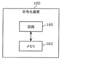
- An encoding apparatus is an encoding apparatus that encodes image information, and includes a memory and a circuit that can access the memory.
- a binarized data sequence is derived from image information according to binarization for arithmetic encoding, includes the binarized data sequence, and the arithmetic encoding is applied to the binarized data sequence
- Output a bit string including application information indicating whether or not, including the binarized data string to which the arithmetic coding is not applied in the output of the bit string, and the binarized data string
- the bit string including information indicating that arithmetic coding is not applied as the application information is output.
- the encoding device or the like can assist in reducing processing delay caused by arithmetic encoding or the like.
- FIG. 1 is a block diagram showing a functional configuration of the encoding apparatus according to Embodiment 1.
- FIG. 2 is a diagram illustrating an example of block division in the first embodiment.
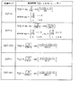
- FIG. 3 is a table showing conversion basis functions corresponding to each conversion type.
- FIG. 4A is a diagram illustrating an example of the shape of a filter used in ALF.
- FIG. 4B is a diagram illustrating another example of the shape of a filter used in ALF.
- FIG. 4C is a diagram illustrating another example of the shape of a filter used in ALF.
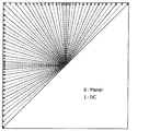
- FIG. 5 is a diagram illustrating 67 intra prediction modes in intra prediction.
- FIG. 6 is a diagram for explaining pattern matching (bilateral matching) between two blocks along the motion trajectory.
- FIG. 1 is a block diagram showing a functional configuration of the encoding apparatus according to Embodiment 1.
- FIG. 2 is a diagram illustrating an example of block division in the first embodiment.
- FIG. 3 is a table showing conversion basis functions
- FIG. 7 is a diagram for explaining pattern matching (template matching) between a template in the current picture and a block in the reference picture.
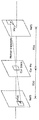
- FIG. 8 is a diagram for explaining a model assuming constant velocity linear motion.
- FIG. 9 is a diagram for explaining the derivation of motion vectors in units of sub-blocks based on the motion vectors of a plurality of adjacent blocks.
- FIG. 10 is a block diagram showing a functional configuration of the decoding apparatus according to the first embodiment.
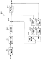
- FIG. 11 is a block diagram showing a detailed functional configuration of the entropy encoding unit in the encoding apparatus according to Embodiment 1.
- FIG. 12 is a block diagram showing a detailed functional configuration of the entropy decoding unit in the decoding apparatus according to Embodiment 1.
- FIG. 13 is a block diagram illustrating a functional configuration of a codec system including the encoding device and the decoding device according to the first embodiment.
- FIG. 14 is a block diagram illustrating an implementation example of the coding apparatus according to Embodiment 1.
- FIG. 15 is a flowchart showing a first coding operation example of the coding apparatus according to Embodiment 1.
- FIG. 16 is a flowchart showing a second coding operation example of the coding apparatus according to Embodiment 1.
- FIG. 17 is a block diagram illustrating an implementation example of the decoding apparatus according to the first embodiment.
- FIG. 18 is a flowchart showing a first decoding operation example of the decoding apparatus according to the first embodiment.
- FIG. 19 is a flowchart showing a second decoding operation example of the decoding apparatus according to the first embodiment.
- FIG. 20 is an overall configuration diagram of a content supply system that implements a content distribution service.
- FIG. 21 is a diagram illustrating an example of a coding structure at the time of scalable coding.
- FIG. 22 is a diagram illustrating an example of a coding structure at the time of scalable coding.
- FIG. 23 is a diagram showing an example of a web page display screen.
- FIG. 24 shows an example of a web page display screen.
- FIG. 25 is a diagram illustrating an example of a smartphone.
- FIG. 26 is a block diagram illustrating a configuration example of a smartphone.
- H. a conventional encoding method.
- arithmetic coding is used to efficiently encode image information.
- CABAC context adaptive binary arithmetic coding method
- a multilevel signal is converted into a binary data string that is a data string of values represented by 0 or 1 by binarization. Then, an occurrence probability of 0 or 1 is selected from a plurality of predetermined occurrence probabilities according to the context such as the data type, and binary arithmetic coding is applied to the binarized data string according to the selected occurrence probability. . Then, the occurrence probability is updated according to the value of 0 or 1 included in the binarized data string.
- binary arithmetic coding is performed according to a variable occurrence probability.
- binary arithmetic coding is performed according to a fixed occurrence probability for a specific data type or the like.
- Such arithmetic coding provides high coding efficiency. In other words, a high compression rate can be obtained by such arithmetic coding.
- an encoding device that encodes image information, and includes a memory and a circuit that can access the memory, and the circuit that can access the memory includes: , Deriving a binarized data string from the image information according to binarization for arithmetic coding, including the binarized data string, and applying the arithmetic coding to the binarized data string Output a bit string including application information indicating whether or not the bit string is output, including the binarized data string to which the arithmetic coding is not applied in the output of the bit string, and the binarized data string The bit string including information indicating that the arithmetic coding is not applied as the application information is output.
- the encoding apparatus can skip arithmetic encoding. Therefore, the encoding apparatus can assist in reducing processing delay caused by arithmetic encoding. Also, the encoding device can effectively use binarization resources related to arithmetic encoding. Also, the encoding device can output a bit string in which the application state of arithmetic encoding can be identified by the application information.
- the circuit includes (i) the binarized data sequence to which the arithmetic encoding is applied at the output of the bit sequence, and the arithmetic encoding is applied to the binary data sequence.
- the second operation of outputting the bit string including information indicating that the arithmetic coding is not applied to the binarized data string as the application information may be switched.
- the encoding apparatus can adaptively switch whether or not to perform arithmetic encoding, and can skip arithmetic encoding adaptively.
- the circuit outputs the bit string including the application information that comprehensively indicates whether or not the arithmetic coding is applied to the binary data string in units including one or more pictures. May be.
- the encoding apparatus can suppress an increase in the code amount and the processing amount related to the application information.
- An encoding apparatus is an encoding apparatus that encodes image information, and includes a memory and a circuit that can access the memory, and the circuit that can access the memory includes: , Deriving a binarized data string from the image information according to binarization for arithmetic coding, and outputting a bit string including the binarized data string, and (i) the arithmetic coding at the output of the bit string (Ii) including the binarized data sequence to which the arithmetic coding is not applied in the output of the bit sequence; An encoding device that switches between a second operation for outputting a bit string may be used.
- the encoding apparatus can adaptively switch whether or not to perform arithmetic encoding, and can skip arithmetic encoding adaptively. Therefore, the encoding apparatus can assist in reducing processing delay caused by arithmetic encoding. Also, the encoding device can effectively use binarization resources related to arithmetic encoding.
- the circuit outputs the bit string including the binarized data string and including application information indicating whether the arithmetic coding is applied to the binarized data string.
- Information including the binarized data sequence to which the arithmetic coding is applied and indicating that the arithmetic coding is applied to the binarized data sequence in the output of the bit string
- the second operation of outputting the bit string including information indicating that the arithmetic coding is not applied to the data string as the application information may be switched.
- the encoding apparatus can output a bit string in which the application state of arithmetic encoding can be identified by the application information.
- the circuit may switch between the first operation and the second operation comprehensively in units including one or more pictures.
- the encoding apparatus can suppress an increase in the processing amount related to switching of the application state of arithmetic encoding.
- the decoding device is a decoding device that decodes image information, and includes a memory and a circuit that can access the memory, and the circuit that can access the memory includes the image Application information that includes a binarized data sequence derived from information according to binarization for arithmetic encoding and indicates whether the arithmetic encoding is applied to the binarized data sequence; The binary data sequence included in the bit sequence including the application information as information indicating that the arithmetic coding is not applied to the binary data sequence, The image information is derived from the binary data sequence to which arithmetic coding is not applied.
- the decoding apparatus can skip arithmetic decoding. Therefore, the decoding apparatus can assist in reducing processing delay caused by arithmetic decoding.
- the decoding device can effectively use the inverse binarization resources related to arithmetic decoding.
- the decoding apparatus can derive image information from a bit string in which the application state of arithmetic coding can be identified by the application information.
- the circuit in the derivation of the image information, includes (i) the bit string that includes information indicating that the arithmetic coding is applied to the binary data string as the application information.
- the second operation for deriving the image information from the binarized data sequence may be switched.
- the decoding apparatus can adaptively switch whether or not to perform arithmetic decoding, and can skip arithmetic decoding adaptively.
- the circuit acquires the bit string including the application information that comprehensively indicates whether or not the arithmetic coding is applied to the binary data string in units including one or more pictures. May be.
- the decoding apparatus can suppress an increase in the code amount and the processing amount related to the application information.
- the decoding device is a decoding device that decodes image information, and includes a memory and a circuit that can access the memory, and the circuit that can access the memory includes the image Obtaining a bit string including a binarized data string derived according to binarization for arithmetic coding from information, deriving the image information from the binarized data string, and (i) in deriving the image information A first operation for deriving the image information from the binarized data sequence included in the bit sequence, to which the arithmetic coding is applied, and (ii) the image information In the derivation, the decoding is performed to switch between the binarized data sequence included in the bit sequence and the second operation for deriving the image information from the binarized data sequence to which the arithmetic coding is not applied. It may be a location.
- the decoding apparatus can adaptively switch whether or not to perform arithmetic decoding, and can skip arithmetic decoding adaptively. Therefore, the decoding apparatus can assist in reducing processing delay caused by arithmetic decoding. In addition, the decoding device can effectively use the inverse binarization resources related to arithmetic decoding.
- the circuit acquires the bit string including the binarized data string and including application information indicating whether or not the arithmetic coding is applied to the binarized data string. i) In the derivation of the image information, the binarized data sequence included in the bit sequence including information indicating that the arithmetic coding is applied to the binarized data sequence as the application information.
- the decoding apparatus can obtain a bit string whose application state of arithmetic coding can be identified by the application information and derive image information.
- the circuit may switch between the first operation and the second operation comprehensively in units including one or more pictures.
- the decoding apparatus can suppress an increase in the processing amount related to switching of the application state of arithmetic coding.
- An encoding method is an encoding method for encoding image information, wherein a binary data string is derived from the image information according to binarization for arithmetic encoding, A bit string including the binarized data string and including application information indicating whether or not the arithmetic coding is applied to the binarized data string; and outputting the bit string at the output of the bit string
- the bit string including the binarized data sequence to which encoding is not applied and including information indicating that the arithmetic encoding is not applied to the binarized data sequence is output as the application information To do.
- a device or the like that executes this encoding method can skip arithmetic encoding. Therefore, an apparatus or the like that executes this encoding method can assist in reducing processing delay caused by arithmetic encoding. Also, an apparatus or the like that executes this encoding method can effectively use binarization resources related to arithmetic encoding. Also, a device or the like that executes this encoding method can output a bit string in which the application state of arithmetic encoding can be identified by the application information.
- An encoding method is an encoding method for encoding image information, wherein a binary data string is derived from the image information according to binarization for arithmetic encoding, (I) a first operation of outputting the bit string including the binarized data string to which the arithmetic coding is applied at the output of the bit string; ii) In the output of the bit string, the encoding method may be switched between a second operation for outputting the bit string including the binarized data string to which the arithmetic coding is not applied.
- a device or the like that executes this encoding method can adaptively switch whether or not to perform arithmetic encoding, and can skip arithmetic encoding adaptively. Therefore, an apparatus or the like that executes this encoding method can assist in reducing processing delay caused by arithmetic encoding. Also, an apparatus or the like that executes this encoding method can effectively use binarization resources related to arithmetic encoding.
- the decoding method is a decoding method for decoding image information, including a binarized data sequence derived from the image information according to binarization for arithmetic coding, and A bit string including application information indicating whether or not the arithmetic coding is applied to the binarized data string, and the arithmetic coding is not applied to the binarized data string
- the image information is derived from the binarized data sequence that is included in the bit sequence including the information indicating that as the applied information, and to which the arithmetic coding is not applied.
- a device or the like executing this decoding method can skip arithmetic decoding. Therefore, an apparatus or the like that executes this decoding method can assist in reducing processing delay caused by arithmetic decoding. In addition, a device or the like that executes this decoding method can effectively utilize the inverse binarization resources related to arithmetic decoding. In addition, an apparatus or the like that executes this decoding method can obtain image information by acquiring a bit string whose arithmetic coding application state can be identified by the application information.
- a decoding method is a decoding method for decoding image information, and includes a bit string including a binarized data string derived from the image information according to binarization for arithmetic coding. Obtaining the image information from the binarized data sequence, and (i) in the derivation of the image information, the binarized data sequence included in the bit sequence, the arithmetic encoding being applied A first operation for deriving the image information from the binarized data sequence, and (ii) in deriving the image information, the binarized data sequence included in the bit sequence, wherein the arithmetic encoding is performed It may be a decoding method for switching between the second operation for deriving the image information from the binarized data sequence not applied.
- an apparatus or the like that executes this decoding method can adaptively switch whether or not to perform arithmetic decoding, and can skip arithmetic decoding adaptively. Therefore, an apparatus or the like that executes this decoding method can assist in reducing processing delay caused by arithmetic decoding.
- a device or the like that executes this decoding method can effectively utilize the inverse binarization resources related to arithmetic decoding.
- these comprehensive or specific aspects may be realized by a system, an apparatus, a method, an integrated circuit, a computer program, or a non-transitory recording medium such as a computer-readable CD-ROM.
- the present invention may be realized by any combination of an apparatus, a method, an integrated circuit, a computer program, and a recording medium.
- FIG. 1 is a block diagram showing a functional configuration of encoding apparatus 100 according to Embodiment 1.
- the encoding device 100 is a moving image / image encoding device that encodes moving images / images in units of blocks.
- an encoding apparatus 100 is an apparatus that encodes an image in units of blocks, and includes a dividing unit 102, a subtracting unit 104, a transforming unit 106, a quantizing unit 108, and entropy encoding.
- Unit 110 inverse quantization unit 112, inverse transform unit 114, addition unit 116, block memory 118, loop filter unit 120, frame memory 122, intra prediction unit 124, inter prediction unit 126, A prediction control unit 128.
- the encoding device 100 is realized by, for example, a general-purpose processor and a memory.
- the processor when the software program stored in the memory is executed by the processor, the processor performs the division unit 102, the subtraction unit 104, the conversion unit 106, the quantization unit 108, the entropy encoding unit 110, and the inverse quantization unit 112.
- the encoding apparatus 100 includes a dividing unit 102, a subtracting unit 104, a transforming unit 106, a quantizing unit 108, an entropy coding unit 110, an inverse quantizing unit 112, an inverse transforming unit 114, an adding unit 116, and a loop filter unit 120.
- the intra prediction unit 124, the inter prediction unit 126, and the prediction control unit 128 may be implemented as one or more dedicated electronic circuits.
- the dividing unit 102 divides each picture included in the input moving image into a plurality of blocks, and outputs each block to the subtracting unit 104.
- the dividing unit 102 first divides a picture into blocks of a fixed size (for example, 128 ⁇ 128).
- This fixed size block may be referred to as a coding tree unit (CTU).
- the dividing unit 102 divides each of the fixed size blocks into blocks of a variable size (for example, 64 ⁇ 64 or less) based on recursive quadtree and / or binary tree block division.
- This variable size block may be referred to as a coding unit (CU), a prediction unit (PU) or a transform unit (TU).
- CU, PU, and TU do not need to be distinguished, and some or all blocks in a picture may be processing units of CU, PU, and TU.
- FIG. 2 is a diagram showing an example of block division in the first embodiment.
- a solid line represents a block boundary by quadtree block division
- a broken line represents a block boundary by binary tree block division.
- the block 10 is a 128 ⁇ 128 pixel square block (128 ⁇ 128 block).
- the 128 ⁇ 128 block 10 is first divided into four square 64 ⁇ 64 blocks (quadtree block division).
- the upper left 64 ⁇ 64 block is further divided vertically into two rectangular 32 ⁇ 64 blocks, and the left 32 ⁇ 64 block is further divided vertically into two rectangular 16 ⁇ 64 blocks (binary tree block division). As a result, the upper left 64 ⁇ 64 block is divided into two 16 ⁇ 64 blocks 11 and 12 and a 32 ⁇ 64 block 13.
- the upper right 64 ⁇ 64 block is horizontally divided into two rectangular 64 ⁇ 32 blocks 14 and 15 (binary tree block division).
- the lower left 64x64 block is divided into four square 32x32 blocks (quadrant block division). Of the four 32 ⁇ 32 blocks, the upper left block and the lower right block are further divided.
- the upper left 32 ⁇ 32 block is vertically divided into two rectangular 16 ⁇ 32 blocks, and the right 16 ⁇ 32 block is further divided horizontally into two 16 ⁇ 16 blocks (binary tree block division).
- the lower right 32 ⁇ 32 block is horizontally divided into two 32 ⁇ 16 blocks (binary tree block division).
- the lower left 64 ⁇ 64 block is divided into a 16 ⁇ 32 block 16, two 16 ⁇ 16 blocks 17 and 18, two 32 ⁇ 32 blocks 19 and 20, and two 32 ⁇ 16 blocks 21 and 22.
- the lower right 64x64 block 23 is not divided.
- the block 10 is divided into 13 variable-size blocks 11 to 23 based on the recursive quadtree and binary tree block division.
- Such division may be called QTBT (quad-tree plus binary tree) division.
- one block is divided into four or two blocks (quadrature tree or binary tree block division), but the division is not limited to this.
- one block may be divided into three blocks (triple tree block division).
- Such a division including a tri-tree block division may be called an MBT (multi type tree) division.
- the subtraction unit 104 subtracts the prediction signal (prediction sample) from the original signal (original sample) in units of blocks divided by the division unit 102. That is, the subtraction unit 104 calculates a prediction error (also referred to as a residual) of a coding target block (hereinafter referred to as a current block). Then, the subtraction unit 104 outputs the calculated prediction error to the conversion unit 106.
- a prediction error also referred to as a residual of a coding target block (hereinafter referred to as a current block).
- the original signal is an input signal of the encoding device 100, and is a signal (for example, a luminance (luma) signal and two color difference (chroma) signals) representing an image of each picture constituting the moving image.
- a signal representing an image may be referred to as a sample.
- the transform unit 106 transforms the prediction error in the spatial domain into a transform factor in the frequency domain, and outputs the transform coefficient to the quantization unit 108. Specifically, the transform unit 106 performs, for example, a predetermined discrete cosine transform (DCT) or discrete sine transform (DST) on a prediction error in the spatial domain.
- DCT discrete cosine transform
- DST discrete sine transform
- the conversion unit 106 adaptively selects a conversion type from a plurality of conversion types, and converts a prediction error into a conversion coefficient using a conversion basis function corresponding to the selected conversion type. May be. Such a conversion may be referred to as EMT (explicit multiple core transform) or AMT (adaptive multiple transform).
- the plurality of conversion types include, for example, DCT-II, DCT-V, DCT-VIII, DST-I and DST-VII.
- FIG. 3 is a table showing conversion basis functions corresponding to each conversion type. In FIG. 3, N indicates the number of input pixels. Selection of a conversion type from among these multiple conversion types may depend on, for example, the type of prediction (intra prediction and inter prediction), or may depend on an intra prediction mode.
- Information indicating whether or not to apply such EMT or AMT (for example, called an AMT flag) and information indicating the selected conversion type are signaled at the CU level.
- AMT flag information indicating whether or not to apply such EMT or AMT
- the signalization of these pieces of information need not be limited to the CU level, but may be other levels (for example, a sequence level, a picture level, a slice level, a tile level, or a CTU level).
- the conversion unit 106 may reconvert the conversion coefficient (conversion result). Such reconversion is sometimes referred to as AST (adaptive secondary transform) or NSST (non-separable secondary transform). For example, the conversion unit 106 performs re-conversion for each sub-block (for example, 4 ⁇ 4 sub-block) included in the block of the conversion coefficient corresponding to the intra prediction error. Information indicating whether or not NSST is applied and information related to the transformation matrix used for NSST are signaled at the CU level. Note that the signalization of these pieces of information need not be limited to the CU level, but may be other levels (for example, a sequence level, a picture level, a slice level, a tile level, or a CTU level).
- the quantization unit 108 quantizes the transform coefficient output from the transform unit 106. Specifically, the quantization unit 108 scans the transform coefficients of the current block in a predetermined scanning order, and quantizes the transform coefficients based on the quantization parameter (QP) corresponding to the scanned transform coefficients. Then, the quantization unit 108 outputs the quantized transform coefficient (hereinafter referred to as a quantization coefficient) of the current block to the entropy encoding unit 110 and the inverse quantization unit 112.
- QP quantization parameter
- the predetermined order is an order for quantization / inverse quantization of transform coefficients.
- the predetermined scanning order is defined in ascending order of frequency (order from low frequency to high frequency) or descending order (order from high frequency to low frequency).
- the quantization parameter is a parameter that defines a quantization step (quantization width). For example, if the value of the quantization parameter increases, the quantization step also increases. That is, if the value of the quantization parameter increases, the quantization error increases.
- the entropy encoding unit 110 generates an encoded signal (encoded bit stream) by performing variable length encoding on the quantization coefficient that is input from the quantization unit 108. Specifically, the entropy encoding unit 110 binarizes the quantization coefficient, for example, and arithmetically encodes the binary signal.
- the inverse quantization unit 112 inversely quantizes the quantization coefficient that is an input from the quantization unit 108. Specifically, the inverse quantization unit 112 inversely quantizes the quantization coefficient of the current block in a predetermined scanning order. Then, the inverse quantization unit 112 outputs the inverse-quantized transform coefficient of the current block to the inverse transform unit 114.
- the inverse transform unit 114 restores the prediction error by inverse transforming the transform coefficient that is an input from the inverse quantization unit 112. Specifically, the inverse transform unit 114 restores the prediction error of the current block by performing an inverse transform corresponding to the transform by the transform unit 106 on the transform coefficient. Then, the inverse transformation unit 114 outputs the restored prediction error to the addition unit 116.
- the restored prediction error does not match the prediction error calculated by the subtraction unit 104 because information is lost due to quantization. That is, the restored prediction error includes a quantization error.
- the adder 116 reconstructs the current block by adding the prediction error input from the inverse transform unit 114 and the prediction signal input from the prediction control unit 128. Then, the adding unit 116 outputs the reconfigured block to the block memory 118 and the loop filter unit 120.
- the reconstructed block is sometimes referred to as a local decoding block.
- the block memory 118 is a storage unit for storing blocks in an encoding target picture (hereinafter referred to as current picture) that are referred to in intra prediction. Specifically, the block memory 118 stores the reconstructed block output from the adding unit 116.
- the loop filter unit 120 applies a loop filter to the block reconstructed by the adding unit 116 and outputs the filtered reconstructed block to the frame memory 122.
- the loop filter is a filter (in-loop filter) used in the encoding loop, and includes, for example, a deblocking filter (DF), a sample adaptive offset (SAO), an adaptive loop filter (ALF), and the like.
- a least square error filter is applied to remove coding distortion. For example, for each 2 ⁇ 2 sub-block in the current block, a plurality of multiples based on the direction of the local gradient and the activity are provided. One filter selected from the filters is applied.
- sub-blocks for example, 2 ⁇ 2 sub-blocks
- a plurality of classes for example, 15 or 25 classes.
- the direction value D of the gradient is derived, for example, by comparing gradients in a plurality of directions (for example, horizontal, vertical, and two diagonal directions).
- the gradient activation value A is derived, for example, by adding gradients in a plurality of directions and quantizing the addition result.
- a filter for a sub-block is determined from among a plurality of filters.
- FIG. 4A to 4C are diagrams showing a plurality of examples of filter shapes used in ALF.
- 4A shows a 5 ⁇ 5 diamond shape filter
- FIG. 4B shows a 7 ⁇ 7 diamond shape filter
- FIG. 4C shows a 9 ⁇ 9 diamond shape filter.
- Information indicating the shape of the filter is signalized at the picture level. It should be noted that the signalization of the information indicating the filter shape need not be limited to the picture level, but may be another level (for example, a sequence level, a slice level, a tile level, a CTU level, or a CU level).
- ON / OFF of ALF is determined at the picture level or the CU level, for example. For example, for luminance, it is determined whether to apply ALF at the CU level, and for color difference, it is determined whether to apply ALF at the picture level.
- Information indicating ALF on / off is signaled at the picture level or the CU level. Signaling of information indicating ALF on / off need not be limited to the picture level or the CU level, and may be performed at other levels (for example, a sequence level, a slice level, a tile level, or a CTU level). Good.
- a coefficient set of a plurality of selectable filters (for example, up to 15 or 25 filters) is signalized at the picture level.
- the signalization of the coefficient set need not be limited to the picture level, but may be another level (for example, sequence level, slice level, tile level, CTU level, CU level, or sub-block level).
- the frame memory 122 is a storage unit for storing a reference picture used for inter prediction, and is sometimes called a frame buffer. Specifically, the frame memory 122 stores the reconstructed block filtered by the loop filter unit 120.
- the intra prediction unit 124 generates a prediction signal (intra prediction signal) by referring to the block in the current picture stored in the block memory 118 and performing intra prediction (also referred to as intra-screen prediction) of the current block. Specifically, the intra prediction unit 124 generates an intra prediction signal by performing intra prediction with reference to a sample (for example, luminance value and color difference value) of a block adjacent to the current block, and performs prediction control on the intra prediction signal. To the unit 128.
- the intra prediction unit 124 performs intra prediction using one of a plurality of predefined intra prediction modes.
- the plurality of intra prediction modes include one or more non-directional prediction modes and a plurality of directional prediction modes.
- One or more non-directional prediction modes are for example H.264. It includes Planar prediction mode and DC prediction mode defined by H.265 / HEVC (High-Efficiency Video Coding) standard (Non-patent Document 1).
- the multiple directionality prediction modes are H. It includes 33-direction prediction modes defined in the H.265 / HEVC standard. In addition to the 33 directions, the plurality of directionality prediction modes may further include 32 direction prediction modes (a total of 65 directionality prediction modes).
- FIG. 5 is a diagram illustrating 67 intra prediction modes (two non-directional prediction modes and 65 directional prediction modes) in intra prediction. The solid line arrows The 33 directions defined in the H.265 / HEVC standard are represented, and the dashed arrow represents the added 32 directions.
- the luminance block may be referred to in the intra prediction of the color difference block. That is, the color difference component of the current block may be predicted based on the luminance component of the current block.
- Such intra prediction is sometimes called CCLM (cross-component linear model) prediction.
- the intra prediction mode (for example, called CCLM mode) of the color difference block which refers to such a luminance block may be added as one of the intra prediction modes of the color difference block.
- the intra prediction unit 124 may correct the pixel value after intra prediction based on the gradient of the reference pixel in the horizontal / vertical direction. Intra prediction with such correction may be called PDPC (position dependent intra prediction combination). Information indicating whether or not PDPC is applied (for example, referred to as a PDPC flag) is signaled, for example, at the CU level.
- the signalization of this information need not be limited to the CU level, but may be another level (for example, a sequence level, a picture level, a slice level, a tile level, or a CTU level).
- the inter prediction unit 126 refers to a reference picture stored in the frame memory 122 and is different from the current picture, and performs inter prediction (also referred to as inter-screen prediction) of the current block, thereby generating a prediction signal (inter prediction signal). Prediction signal). Inter prediction is performed in units of a current block or a sub-block (for example, 4 ⁇ 4 block) in the current block. For example, the inter prediction unit 126 performs motion estimation in the reference picture for the current block or sub-block. Then, the inter prediction unit 126 generates an inter prediction signal of the current block or sub-block by performing motion compensation using motion information (for example, a motion vector) obtained by motion search. Then, the inter prediction unit 126 outputs the generated inter prediction signal to the prediction control unit 128.
- inter prediction also referred to as inter-screen prediction
- a motion vector predictor may be used for signalizing the motion vector. That is, the difference between the motion vector and the predicted motion vector may be signaled.
- an inter prediction signal may be generated using not only the motion information of the current block obtained by motion search but also the motion information of adjacent blocks. Specifically, the inter prediction signal is generated in units of sub-blocks in the current block by weighted addition of the prediction signal based on the motion information obtained by motion search and the prediction signal based on the motion information of adjacent blocks. May be.
- Such inter prediction motion compensation
- OBMC overlapped block motion compensation
- OBMC block size information indicating the size of a sub-block for OBMC
- OBMC flag information indicating whether or not to apply the OBMC mode
- the level of signalization of these information does not need to be limited to the sequence level and the CU level, and may be other levels (for example, a picture level, a slice level, a tile level, a CTU level, or a sub-block level). Good.
- the motion information may be derived on the decoding device side without being converted into a signal.
- H.M. A merge mode defined in the H.265 / HEVC standard may be used.
- the motion information may be derived by performing motion search on the decoding device side. In this case, motion search is performed without using the pixel value of the current block.
- the mode in which the motion search is performed on the decoding device side is sometimes referred to as a PMMVD (patterned motion vector derivation) mode or an FRUC (frame rate up-conversion) mode.
- PMMVD patterned motion vector derivation
- FRUC frame rate up-conversion
- one of the candidates included in the merge list is selected as a search start position by pattern matching.
- the pattern matching the first pattern matching or the second pattern matching is used.
- the first pattern matching and the second pattern matching may be referred to as bilateral matching and template matching, respectively.
- pattern matching is performed between two blocks in two different reference pictures that follow the motion trajectory of the current block.
- FIG. 6 is a diagram for explaining pattern matching (bilateral matching) between two blocks along a motion trajectory.
- pattern matching bilateral matching
- two blocks along the motion trajectory of the current block (Cur block) and two blocks in two different reference pictures (Ref0, Ref1) are used.
- Ref0, Ref1 two blocks in two different reference pictures
- the motion vectors (MV0, MV1) pointing to the two reference blocks are temporal distances between the current picture (Cur Pic) and the two reference pictures (Ref0, Ref1). It is proportional to (TD0, TD1).
- the first pattern matching uses a mirror-symmetric bi-directional motion vector Is derived.
- pattern matching is performed between a template in the current picture (a block adjacent to the current block in the current picture (for example, an upper and / or left adjacent block)) and a block in the reference picture.
- FIG. 7 is a diagram for explaining pattern matching (template matching) between a template in the current picture and a block in the reference picture.
- the current block is searched by searching the reference picture (Ref0) for the block that most closely matches the block adjacent to the current block (Cur block) in the current picture (Cur Pic).
- Ref0 the reference picture
- FRUC flag Information indicating whether or not to apply such FRUC mode
- FRUC flag information indicating whether or not to apply such FRUC mode
- the FRUC mode is applied (for example, when the FRUC flag is true)
- information indicating the pattern matching method (first pattern matching or second pattern matching) (for example, called the FRUC mode flag) is signaled at the CU level. It becomes. Note that the signalization of these pieces of information need not be limited to the CU level, but may be other levels (for example, sequence level, picture level, slice level, tile level, CTU level, or sub-block level). .
- motion information may be derived on the decoding device side by a method different from motion search.
- the motion vector correction amount may be calculated using a peripheral pixel value for each pixel based on a model assuming constant velocity linear motion.
- BIO bi-directional optical flow
- FIG. 8 is a diagram for explaining a model assuming constant velocity linear motion.
- (v x , v y ) indicates a velocity vector
- ⁇ 0 and ⁇ 1 are the time between the current picture (Cur Pic) and two reference pictures (Ref 0 , Ref 1 ), respectively.
- the distance. (MVx 0 , MVy 0 ) indicates a motion vector corresponding to the reference picture Ref 0
- (MVx 1 , MVy 1 ) indicates a motion vector corresponding to the reference picture Ref 1 .
- This optical flow equation consists of (i) the product of the time derivative of the luminance value, (ii) the horizontal component of the horizontal velocity and the spatial gradient of the reference image, and (iii) the vertical velocity and the spatial gradient of the reference image. Indicates that the sum of the products of the vertical components of is equal to zero. Based on a combination of this optical flow equation and Hermite interpolation, a block-based motion vector obtained from a merge list or the like is corrected in pixel units.
- the motion vector may be derived on the decoding device side by a method different from the derivation of the motion vector based on the model assuming constant velocity linear motion.
- a motion vector may be derived for each subblock based on the motion vectors of a plurality of adjacent blocks.
- This mode may be referred to as an affine motion compensation prediction mode.
- FIG. 9 is a diagram for explaining the derivation of motion vectors in units of sub-blocks based on the motion vectors of a plurality of adjacent blocks.
- the current block includes 16 4 ⁇ 4 sub-blocks.
- the motion vector v 0 of the upper left corner control point of the current block is derived based on the motion vector of the adjacent block
- the motion vector v 1 of the upper right corner control point of the current block is derived based on the motion vector of the adjacent sub block. Is done.
- the motion vector (v x , v y ) of each sub-block in the current block is derived by the following equation (2).
- x and y indicate the horizontal position and vertical position of the sub-block, respectively, and w indicates a predetermined weight coefficient.
- Such an affine motion compensation prediction mode may include several modes in which the motion vector derivation methods of the upper left and upper right corner control points are different.
- Information indicating such an affine motion compensation prediction mode (for example, called an affine flag) is signaled at the CU level. Note that the information indicating the affine motion compensation prediction mode need not be limited to the CU level, but other levels (for example, sequence level, picture level, slice level, tile level, CTU level, or sub-block level). ).
- the prediction control unit 128 selects either the intra prediction signal or the inter prediction signal, and outputs the selected signal to the subtraction unit 104 and the addition unit 116 as a prediction signal.
- FIG. 10 is a block diagram showing a functional configuration of decoding apparatus 200 according to Embodiment 1.
- the decoding device 200 is a moving image / image decoding device that decodes moving images / images in units of blocks.
- the decoding device 200 includes an entropy decoding unit 202, an inverse quantization unit 204, an inverse transformation unit 206, an addition unit 208, a block memory 210, a loop filter unit 212, and a frame memory 214. And an intra prediction unit 216, an inter prediction unit 218, and a prediction control unit 220.
- the decoding device 200 is realized by, for example, a general-purpose processor and a memory.
- the processor executes the entropy decoding unit 202, the inverse quantization unit 204, the inverse transformation unit 206, the addition unit 208, the loop filter unit 212, and the intra prediction unit. 216, the inter prediction unit 218, and the prediction control unit 220.
- the decoding apparatus 200 is dedicated to the entropy decoding unit 202, the inverse quantization unit 204, the inverse transformation unit 206, the addition unit 208, the loop filter unit 212, the intra prediction unit 216, the inter prediction unit 218, and the prediction control unit 220. It may be realized as one or more electronic circuits.
- the entropy decoding unit 202 performs entropy decoding on the encoded bit stream. Specifically, the entropy decoding unit 202 performs arithmetic decoding from a coded bitstream to a binary signal, for example. Then, the entropy decoding unit 202 debinarizes the binary signal. As a result, the entropy decoding unit 202 outputs the quantized coefficient to the inverse quantization unit 204 in units of blocks.
- the inverse quantization unit 204 inversely quantizes the quantization coefficient of a decoding target block (hereinafter referred to as a current block) that is an input from the entropy decoding unit 202. Specifically, the inverse quantization unit 204 inversely quantizes each quantization coefficient of the current block based on the quantization parameter corresponding to the quantization coefficient. Then, the inverse quantization unit 204 outputs the quantization coefficient (that is, the transform coefficient) obtained by inverse quantization of the current block to the inverse transform unit 206.
- a decoding target block hereinafter referred to as a current block
- the inverse quantization unit 204 inversely quantizes each quantization coefficient of the current block based on the quantization parameter corresponding to the quantization coefficient. Then, the inverse quantization unit 204 outputs the quantization coefficient (that is, the transform coefficient) obtained by inverse quantization of the current block to the inverse transform unit 206.
- the inverse transform unit 206 restores the prediction error by inverse transforming the transform coefficient that is an input from the inverse quantization unit 204.
- the inverse conversion unit 206 determines the current block based on the information indicating the read conversion type. Inversely transform the conversion coefficient of.
- the inverse conversion unit 206 reconverts the converted conversion coefficient (conversion result).
- the adder 208 reconstructs the current block by adding the prediction error input from the inverse transform unit 206 and the prediction signal input from the prediction control unit 220. Then, the adding unit 208 outputs the reconfigured block to the block memory 210 and the loop filter unit 212.
- the block memory 210 is a storage unit for storing a block that is referred to in intra prediction and that is within a decoding target picture (hereinafter referred to as a current picture). Specifically, the block memory 210 stores the reconstructed block output from the adding unit 208.
- the loop filter unit 212 applies a loop filter to the block reconstructed by the adding unit 208, and outputs the filtered reconstructed block to the frame memory 214, the display device, and the like.
- one filter is selected from the plurality of filters based on the local gradient direction and activity, The selected filter is applied to the reconstruction block.
- the frame memory 214 is a storage unit for storing a reference picture used for inter prediction, and is sometimes called a frame buffer. Specifically, the frame memory 214 stores the reconstructed block filtered by the loop filter unit 212.
- the intra prediction unit 216 performs intra prediction with reference to the block in the current picture stored in the block memory 210 based on the intra prediction mode read from the encoded bitstream, so that a prediction signal (intra prediction Signal). Specifically, the intra prediction unit 216 generates an intra prediction signal by performing intra prediction with reference to a sample (for example, luminance value and color difference value) of a block adjacent to the current block, and performs prediction control on the intra prediction signal. Output to the unit 220.
- a prediction signal for example, luminance value and color difference value
- the intra prediction unit 216 may predict the color difference component of the current block based on the luminance component of the current block.
- the intra prediction unit 216 corrects the pixel value after intra prediction based on the gradient of the reference pixel in the horizontal / vertical direction.
- the inter prediction unit 218 refers to the reference picture stored in the frame memory 214 and predicts the current block. Prediction is performed in units of a current block or a sub-block (for example, 4 ⁇ 4 block) in the current block. For example, the inter prediction unit 126 generates an inter prediction signal of the current block or sub-block by performing motion compensation using motion information (for example, a motion vector) read from the encoded bitstream, and generates the inter prediction signal. The result is output to the prediction control unit 128.
- motion information for example, a motion vector
- the inter prediction unit 218 When the information read from the encoded bitstream indicates that the OBMC mode is to be applied, the inter prediction unit 218 includes not only the motion information of the current block obtained by motion search but also the motion information of adjacent blocks. To generate an inter prediction signal.
- the inter prediction unit 218 follows the pattern matching method (bilateral matching or template matching) read from the encoded stream. Motion information is derived by performing motion search. Then, the inter prediction unit 218 performs motion compensation using the derived motion information.
- the inter prediction unit 218 derives a motion vector based on a model assuming constant velocity linear motion. Also, when the information read from the encoded bitstream indicates that the affine motion compensated prediction mode is applied, the inter prediction unit 218 determines the motion vector in units of subblocks based on the motion vectors of a plurality of adjacent blocks. Is derived.
- the prediction control unit 220 selects either the intra prediction signal or the inter prediction signal, and outputs the selected signal to the adding unit 208 as a prediction signal.
- FIG. 11 is a block diagram showing a detailed functional configuration of entropy coding unit 110 in coding apparatus 100 according to Embodiment 1.
- the entropy coding unit 110 generates a bit string by applying variable length coding to the quantized coefficient output from the quantization unit 108, and outputs the generated bit string.
- This bit string corresponds to encoded image information and is also called an encoded signal, an encoded bit stream, or an encoded bit string.
- the entropy encoding unit 110 includes a binarization unit 132, a switching unit 134, an intermediate buffer 136, an arithmetic encoding unit 138, a switching unit 140, and a multiplexing unit 142. . Then, the entropy encoding unit 110 stores the generated bit string in the output buffer 144 by generating a bit string and outputting the generated bit string. The bit string stored in the output buffer 144 is output from the output buffer 144 as appropriate.
- the entropy encoding unit 110 may include an output buffer 144.
- the binarization unit 132 binarizes the quantization coefficient and the like. Specifically, the binarization unit 132 converts the quantized frequency conversion coefficient or the like into a data string having a value expressed by, for example, 0 or 1, and outputs the obtained data string. Hereinafter, this data string is also referred to as a binarized data string.
- the binarization performed by the binarization unit 132 is binarization for arithmetic coding, and more specifically, binarization for performing binary arithmetic coding. That is, the binarization unit 132 derives a binarized data string of image information according to binarization for arithmetic coding.
- binarization methods include unary binarization, truncated unary binarization, unary / kth-order exponent Golomb / joint binarization, fixed-length binarization, and table reference.
- entropy coding of the context adaptive binary arithmetic coding scheme is performed by binarization in the binarization unit 132 and arithmetic coding in the arithmetic coding unit 138.
- the context adaptive binary arithmetic coding scheme is also called CABAC.
- the binarization performed by the binarization unit 132 can also be expressed as binarization for the context adaptive binary arithmetic coding scheme.
- the switching units 134 and 140 operate in conjunction with the mode information, and switch whether to apply arithmetic coding to the binary data string. For example, the switching units 134 and 140 switch whether to apply arithmetic coding to the binarized data sequence according to mode information given from the outside of the encoding apparatus 100.
- the mode information may be given as an instruction from the user or the host system.
- this mode information selectively indicates the first mode and the second mode. That is, the mode information indicates one mode selected from the first mode and the second mode. For example, in the first mode, arithmetic coding is applied to the binarized data sequence, and in the second mode, arithmetic coding is not applied to the binarized data sequence.
- the switching unit 134 outputs the binarized data sequence output from the binarizing unit 132 to the intermediate buffer 136, thereby converting the binarized data sequence.
- the arithmetic encoding unit 138 applies arithmetic encoding to the binarized data sequence stored in the intermediate buffer 136, and outputs a binary data sequence to which arithmetic encoding is applied.
- the switching unit 140 outputs the binary data sequence output from the arithmetic encoding unit 138 to the multiplexing unit 142.
- the switching unit 134 when the mode information indicates the second mode, the switching unit 134 outputs the binarized data string output from the binarizing unit 132 to the switching unit 140 as it is. Then, the switching unit 140 outputs the binarized data sequence output from the switching unit 134 to the multiplexing unit 142. That is, arithmetic coding is bypassed. In order to avoid confusion with bypass arithmetic encoding, which is one mode of arithmetic encoding, bypassing arithmetic encoding may be expressed as skipping arithmetic encoding.
- the mode information and mode can also be expressed as delay mode information and delay mode.
- the first mode is a normal mode
- the second mode is a low delay mode.
- the processing delay is reduced compared to the first mode.
- the intermediate buffer 136 is a storage unit for storing a binarized data string, and is also called an intermediate memory.
- a delay occurs in the arithmetic coding performed by the arithmetic coding unit 138.
- the delay amount fluctuates depending on the contents of the binarized data string.
- the intermediate buffer 136 absorbs the fluctuation of the delay amount, and the subsequent processing is performed smoothly. Note that inputting data to a storage unit such as the intermediate buffer 136 corresponds to storing data in the storage unit, and outputting data from the storage unit corresponds to reading data from the storage unit.
- the arithmetic encoding unit 138 performs arithmetic encoding. Specifically, the arithmetic coding unit 138 reads the binarized data sequence stored in the intermediate buffer 136 and applies arithmetic coding to the binarized data sequence. The arithmetic encoding unit 138 may apply arithmetic encoding corresponding to the context adaptive binary arithmetic encoding scheme to the binary data string.
- the arithmetic encoding unit 138 selects the occurrence probability of the value according to the context such as the data type, performs arithmetic encoding according to the selected occurrence probability, and updates the occurrence probability according to the result of the arithmetic encoding. That is, the arithmetic encoding unit 138 performs arithmetic encoding according to a variable occurrence probability. Arithmetic coding performed according to a variable occurrence probability is also referred to as context adaptive arithmetic coding.
- the arithmetic encoding unit 138 may perform arithmetic encoding according to a fixed occurrence probability for a specific data type or the like. Specifically, the arithmetic encoding unit 138 may perform arithmetic encoding according to an occurrence probability of 50% as an occurrence probability of 0 or 1. Arithmetic coding performed according to a fixed occurrence probability is also called bypass arithmetic coding.
- the multiplexing unit 142 multiplexes the mode information and the binarized data string, and generates a bit string including the mode information and the binarized data string. Then, the multiplexing unit 142 stores the bit string in the output buffer 144 by outputting the bit string to the output buffer 144. The bit string stored in the output buffer 144 is output from the output buffer 144 as appropriate. That is, the multiplexing unit 142 outputs a bit string via the output buffer 144.
- the mode information may be included in the bit string as an upper parameter.
- the mode information may be included in an SPS (sequence parameter set) in the bit string, may be included in a PPS (picture parameter set) in the bit string, or a slice header in the bit string. May be included.
- SPS sequence parameter set
- PPS picture parameter set
- the mode information included in the bit string is expressed by one or more bits.
- the binarized data string may be included in the slice data.
- the binarized data string may be a binarized data string to which arithmetic coding is applied, or may be a binarized data string to which arithmetic coding is not applied.
- the mode information included in the bit string can also be expressed as application information indicating whether or not arithmetic coding is applied to the binary data string included in the bit string.
- the mode information may be included in the bit string as application information indicating whether or not arithmetic coding is applied to the binarized data string. This application information may indicate whether the bit string includes a binary data string to which arithmetic coding is applied or whether the bit string includes a binary data string to which arithmetic coding is not applied.
- the mode information may not be included in the bit string when the mode information is exchanged in the host system or when the mode information is predetermined. That is, in this case, multiplexing does not have to be performed.
- the output buffer 144 is a storage unit for storing a bit string, and is also called a CPB (Coded Picture Buffer) or an output memory.
- a bit string obtained by encoding image information by the encoding device 100 is stored in the output buffer 144.
- the bit string stored in the output buffer 144 is output as appropriate, and is multiplexed with, for example, an encoded audio signal.
- FIG. 12 is a block diagram showing a detailed functional configuration of entropy decoding section 202 in decoding apparatus 200 according to Embodiment 1.
- the entropy decoding unit 202 performs entropy decoding on the bit string input via the input buffer 232 to derive a quantization coefficient and the like.
- This bit string is, for example, a bit string generated by the encoding apparatus 100 and may have the above-described data configuration.
- the entropy decoding unit 202 includes a separation unit 234, a switching unit 236, an arithmetic decoding unit 238, an intermediate buffer 240, a switching unit 242, and an inverse binarization unit 244.
- the entropy decoding unit 202 may include an input buffer 232.
- the input buffer 232 is a storage unit for storing a bit string, and is also called a CPB or an input memory.
- the bit string decoded by the decoding device 200 is separated from, for example, an encoded audio signal and stored in the input buffer 232. Then, the decoding device 200 reads the bit string stored in the input buffer 232 and decodes the bit string.
- the separation unit 234 acquires the bit string from the input buffer 232, separates the mode information and the binarized data string from the bit string, and outputs the mode information and the binarized data string. That is, the separation unit 234 acquires a bit string including the mode information and the binarized data string via the input buffer 232, and outputs the mode information and the binarized data string included in the bit string.
- the binarized data string may be a binarized data string to which arithmetic coding is applied, or may be a binarized data string to which arithmetic coding is not applied.
- the mode information can also be expressed as application information indicating whether or not arithmetic coding is applied to the binary data string included in the bit string.
- the mode information may not be included in the bit string. In this case, separation and output of mode information may not be performed.
- the mode information may be given as an instruction from the outside of the decoding apparatus 200, specifically, from a user or a host system.
- the switching units 236 and 242 operate in conjunction with the mode information obtained from the separation unit 234 and the like, and switch whether to apply arithmetic decoding to the binarized data string. For example, of the first mode and the second mode selectively indicated by the mode information, in the first mode, arithmetic decoding is applied to the binarized data sequence, and in the second mode, the binarized data sequence is applied. Arithmetic decoding is not applied.
- the switching unit 236 outputs the binarized data sequence output from the separation unit 234 to the arithmetic decoding unit 238. Then, the arithmetic decoding unit 238 applies arithmetic decoding to the binarized data sequence and outputs the binarized data sequence to which the arithmetic decoding is applied, so that the binarized data sequence to which the arithmetic decoding is applied Is stored in the intermediate buffer 240.
- the switching unit 242 appropriately acquires the binarized data string stored in the intermediate buffer 240 and outputs the binarized data string acquired from the intermediate buffer 240 to the inverse binarization unit 244.
- the switching unit 236 outputs the binarized data string output from the separation unit 234 to the switching unit 242 as it is. Then, the switching unit 242 outputs the binarized data string output from the switching unit 236 to the inverse binarization unit 244. That is, arithmetic decoding is bypassed.
- bypassing arithmetic decoding may be expressed as skipping arithmetic decoding.
- the arithmetic decoding unit 238 performs arithmetic decoding. Specifically, the arithmetic decoding unit 238 applies arithmetic decoding to the binarized data sequence to which arithmetic coding is applied, and outputs the binarized data sequence to which arithmetic decoding is applied.
- the binarized data sequence to which decoding is applied is stored in the intermediate buffer 240.
- the binarized data sequence to which arithmetic decoding is applied corresponds to the original binarized data sequence to which arithmetic coding is not applied.
- the arithmetic encoding unit 138 may apply arithmetic decoding corresponding to the context adaptive binary arithmetic encoding scheme to the binary data string.
- the arithmetic decoding unit 238 selects the occurrence probability of the value according to the context such as the data type, performs arithmetic decoding according to the selected occurrence probability, and updates the occurrence probability according to the result of the arithmetic decoding. That is, the arithmetic decoding unit 238 performs arithmetic decoding according to a variable occurrence probability. Arithmetic decoding performed according to a variable occurrence probability is also called context adaptive arithmetic decoding.
- the arithmetic decoding unit 238 may perform arithmetic decoding according to a fixed occurrence probability for a specific data type or the like. Specifically, the arithmetic decoding unit 238 may perform arithmetic decoding according to the occurrence probability of 50% as the occurrence probability of 0 or 1. Arithmetic decoding performed according to a fixed occurrence probability is also called bypass arithmetic decoding.
- the intermediate buffer 240 is a storage unit for storing an arithmetically decoded binary data string, and is also called an intermediate memory.
- a delay occurs in the arithmetic decoding performed by the arithmetic decoding unit 238, a delay occurs.
- the delay amount fluctuates depending on the contents of the binarized data string.
- the intermediate buffer 240 absorbs the fluctuation of the delay amount, and the subsequent processing is performed smoothly.
- the inverse binarization unit 244 derives a quantization coefficient and the like by performing inverse binarization on the binarized data string. Specifically, the inverse binarization unit 244 converts, for example, a binarized data string having a value represented by 0 or 1 into a quantized frequency conversion coefficient or the like, and converts the quantized frequency conversion coefficient or the like. Output to the inverse quantization unit 204. Further, the inverse binarization performed by the inverse binarization unit 244 is an inverse binarization corresponding to the binarization for arithmetic coding, and more specifically, for performing binary arithmetic coding. This is inverse binarization corresponding to binarization.
- entropy decoding of the context adaptive binary arithmetic coding scheme is performed by arithmetic decoding in the arithmetic decoding unit 238 and inverse binarization in the inverse binarization unit 244. That is, the inverse binarization unit 244 may perform inverse binarization according to the context adaptive binary arithmetic coding method. Inverse binarization is also called multi-value quantization.
- FIG. 13 is a block diagram showing a functional configuration of codec system 300 including encoding apparatus 100 and decoding apparatus 200 according to Embodiment 1.
- the codec system 300 includes a transmission device 150 and a reception device 250, and performs encoding, transmission, reception, and decoding of image information.
- the transmission device 150 includes a transmission control unit 152, an encoding device 100, and an output buffer 144, and encodes and transmits image information.
- the reception device 250 includes a reception control unit 252, an input buffer 232, and a decoding device 200, and receives and decodes encoded image information.
- Codec capability refers to the capability associated with encoding and decoding of image information. Thereby, the encoding method including the first mode or the second mode described above is determined.
- the transmission control unit 152 and the reception control unit 252 exchange information regarding the codec capabilities of the encoding device 100 and the decoding device 200. Then, the transmission control unit 152 and the reception control unit 252 determine an encoding method including the first mode or the second mode.
- a first mode in which arithmetic coding is performed or a second mode in which arithmetic coding is not performed is used for encoding and decoding according to a mode supported by both the encoding device 100 and the decoding device 200. It may be determined as a mode. When both the first mode and the second mode are supported, the first mode or the second mode may be determined as a mode used for encoding and decoding according to a predetermined priority order.
- the first mode a processing delay occurs, but an increase in code amount or image quality deterioration is suppressed.
- the processing delay is suppressed, but the code amount increases or the image quality deteriorates. Therefore, in an environment where priority is given to suppressing an increase in code amount or image quality degradation, the first mode may be determined in advance as a mode prioritized over the second mode. Further, in an environment where suppression of processing delay is prioritized, the second mode may be determined in advance as a mode prioritized over the first mode.
- the transmission control unit 152 notifies the encoding device 100 of the determined encoding method, and the reception control unit 252 notifies the decoding device 200 of the determined encoding method.
- the encoding device 100 encodes image information according to the notified encoding method, and the decoding device 200 decodes the image information by a decoding method corresponding to the notified encoding method.
- the transmission control unit 152 notifies the encoding apparatus 100 of mode information indicating a mode determined from the first mode and the second mode as an instruction.
- the reception control unit 252 notifies the decoding apparatus 200 of mode information indicating the same mode determined from the first mode and the second mode as an instruction.
- the encoding device 100 includes a binary data string to which arithmetic coding is applied or a bit string that includes, in slice data, a binary data string to which arithmetic coding is not applied. Is output.
- the decoding apparatus 200 is applied to the binary data string that is included in the bit string slice data and to which arithmetic coding is applied, or is included in the bit string slice data. Image information is derived from the binarized data string that is not.
- the codec capability may not be exchanged.
- the transmission control unit 152 and the reception control unit 252 may notify the encoding apparatus 100 and the decoding apparatus 200 of an encoding scheme including the first mode or the second mode in a fixed manner. Or the encoding apparatus 100 and the decoding apparatus 200 may hold
- the mode used for encoding and decoding may always be fixed to one mode of the first mode and the second mode.
- the mode information may be included as an upper parameter in an SPS, PPS, slice header, or the like in the bit string.
- the decoding apparatus 200 can switch whether or not to apply arithmetic decoding to the binarized data string included in the bit string according to the mode information included in the bit string.
- low_delay_hrd_flag indicating the low-delay HRD mode defined by H.265 may be used as the mode information.
- the mode information may be information different from low_delay_hrd_flag or the like. In this case, since the application of arithmetic coding and the HRD mode can be switched separately, the delay amount can be more flexibly adapted to an upper layer application or the like.
- FIG. 14 is a block diagram illustrating an implementation example of the encoding apparatus 100 according to Embodiment 1.
- the encoding device 100 includes a circuit 160 and a memory 162.
- a plurality of components of the encoding device 100 illustrated in FIGS. 1 and 11 are implemented by the circuit 160 and the memory 162 illustrated in FIG.
- the circuit 160 is a circuit that performs information processing and is a circuit that can access the memory 162.
- the circuit 160 is a dedicated or general-purpose electronic circuit that encodes image information.
- the circuit 160 may be a processor such as a CPU.
- the circuit 160 may be an aggregate of a plurality of electronic circuits. Further, for example, the circuit 160 may serve as a plurality of constituent elements excluding the constituent elements for storing information among the plurality of constituent elements of the encoding device 100 illustrated in FIGS. 1 and 11. .
- the memory 162 is a general purpose or dedicated memory in which information for the circuit 160 to encode image information is stored.
- the memory 162 may be an electronic circuit or may be connected to the circuit 160.
- the memory 162 may be an aggregate of a plurality of electronic circuits. Further, the memory 162 may be a magnetic disk or an optical disk, or may be expressed as a storage or a recording medium.
- the memory 162 may be a non-volatile memory or a volatile memory.
- the memory 162 may store image information to be encoded, or may store a bit string corresponding to the encoded image information.
- the memory 162 may store a program for the circuit 160 to encode image information.
- the circuit 160 may serve as a component for storing information among a plurality of components of the encoding device 100 illustrated in FIGS. 1 and 11.
- the memory 162 may serve as the block memory 118 and the frame memory 122 illustrated in FIG. 1, or may serve as the intermediate buffer 136 illustrated in FIG.
- not all of the plurality of components shown in FIG. 1 and FIG. 11 or the like may be mounted, or all of the plurality of processes described above may not be performed. Some of the plurality of components shown in FIG. 1 and FIG. 11 and the like may be included in another device, and some of the plurality of processes described above may be executed by another device. Good.
- encoding device 100 a part of the plurality of components shown in FIG. 1 and FIG. 11 and the like are mounted, and a part of the plurality of processes described above is performed, thereby performing arithmetic encoding. Reduction of generated processing delay may be supported.
- FIG. 15 is a flowchart showing a first encoding operation example of the encoding apparatus 100 according to Embodiment 1. For example, the operation shown in FIG. 15 is performed by the circuit 160 of the encoding device 100 shown in FIG. 14, whereby the image information is encoded.
- the circuit 160 derives a binarized data sequence from image information according to binarization for arithmetic coding (S101).
- the image information is information indicating an image.
- the image information may be information indicating a quantization coefficient obtained from the image by performing the above-described conversion, quantization, prediction, and the like.
- the image information may be information indicating pixel values obtained from the image without performing the above-described conversion, quantization, prediction, and the like.
- the circuit 160 outputs a bit string including a binarized data string to which arithmetic coding is not applied (S102).
- the circuit 160 outputs a bit string including a binarized data string and including application information indicating whether arithmetic coding is applied to the binarized data string.
- the circuit 160 includes, as application information, a binarized data string to which arithmetic coding is not applied and information indicating that arithmetic coding is not applied to the binarized data string. Output a bit string.
- the encoding apparatus 100 can skip arithmetic encoding. Therefore, the encoding apparatus 100 can assist in reducing processing delay caused by arithmetic encoding. Also, the encoding apparatus 100 can effectively use binarization resources related to arithmetic encoding. Also, the encoding apparatus 100 can output a bit string in which the application state of arithmetic encoding can be identified by application information.
- the encoding apparatus 100 may not perform other operations.
- the encoding apparatus 100 can assist in reducing processing delay caused by arithmetic encoding.
- the circuit 160 may switch between the first operation and the second operation.
- the circuit 160 includes the binarized data sequence to which arithmetic coding is applied, and applies information indicating that arithmetic coding is applied to the binarized data sequence to be applied information
- the circuit 160 includes the binarized data string to which the arithmetic coding is not applied, and applies information indicating that the arithmetic coding is not applied to the binarized data string to the application information.
- the encoding apparatus 100 can adaptively switch whether or not to perform arithmetic encoding, and can adaptively skip arithmetic encoding.
- the circuit 160 can perform both the first operation and the second operation at different timings by switching between the first operation and the second operation. Note that the first operation and the second operation performed by the circuit 160 can also be expressed as a first output operation and a second output operation, respectively.
- the circuit 160 may switch between the first operation and the second operation comprehensively in units including one or more pictures. Thereby, the encoding apparatus 100 can suppress the increase in the processing amount regarding the switching of the application state of arithmetic encoding.
- the circuit 160 may switch between the first operation and the second operation according to information given from the outside of the encoding device 100, or according to information held inside the encoding device 100.
- the first operation and the second operation may be switched. Accordingly, the circuit 160 can appropriately switch between the first operation and the second operation according to information outside or inside the encoding device 100.
- the circuit 160 may output a bit string including application information that comprehensively indicates whether or not arithmetic coding is applied to the binarized data string in units including one or more pictures.
- the application information includes one or more pictures indicating whether a bit string includes a binary data string to which arithmetic coding is applied or whether a bit string includes a binary data string to which arithmetic coding is not applied. You may show comprehensively by the unit to include. Thereby, the encoding apparatus 100 can suppress an increase in the code amount and the processing amount related to the application information.
- FIG. 16 is a flowchart showing a second encoding operation example of the encoding apparatus 100 according to Embodiment 1. For example, the operation shown in FIG. 16 is performed by the circuit 160 of the encoding device 100 shown in FIG. 14, whereby the image information is encoded.
- the circuit 160 derives a binarized data sequence from image information according to binarization for arithmetic coding (S111). This operation is the same as the derivation process (S101) in FIG.
- the circuit 160 switches between the first operation and the second operation (S112).
- the circuit 160 In the first operation, the circuit 160 outputs a bit string including a binary data string to which arithmetic coding is applied (S113).
- the circuit 160 In the second operation, the circuit 160 outputs a bit string including a binarized data string to which arithmetic coding is not applied (S114).
- the encoding apparatus 100 can adaptively switch whether or not to perform arithmetic encoding, and can adaptively skip arithmetic encoding. Therefore, the encoding apparatus 100 can assist in reducing processing delay caused by arithmetic encoding. Also, the encoding apparatus 100 can effectively use binarization resources related to arithmetic encoding. In addition, the circuit 160 can perform both the first operation and the second operation at different timings by switching between the first operation and the second operation.
- the encoding apparatus 100 may not perform other operations.
- the encoding apparatus 100 can assist in reducing processing delay caused by arithmetic encoding.
- the circuit 160 may output a bit string including a binarized data string and including application information indicating whether or not arithmetic coding is applied to the binarized data string.
- the circuit 160 includes the binarized data sequence to which arithmetic coding is applied, and information indicating that arithmetic coding is applied to the binary data sequence. A bit string included as application information may be output.
- the circuit 160 includes information indicating that a binary data string to which arithmetic coding is not applied and that arithmetic coding is not applied to the binary data string. A bit string included as application information may be output.
- the encoding apparatus 100 can output a bit string in which the application state of arithmetic encoding can be identified by the application information.
- the circuit 160 may switch between the first operation and the second operation in accordance with information given from the outside of the encoding device 100 as in the first encoding operation example.
- the first operation and the second operation may be switched according to the information held inside.
- the circuit 160 may switch between the first operation and the second operation comprehensively in units including one or more pictures, as in the first encoding operation example. Further, for example, as in the first encoding operation example, the circuit 160 comprehensively indicates whether or not arithmetic encoding is applied to the binary data sequence in units including one or more pictures. A bit string including information may be output.
- FIG. 17 is a block diagram illustrating an implementation example of the decoding apparatus 200 according to the first embodiment.
- the decoding device 200 includes a circuit 260 and a memory 262.
- a plurality of components of the decoding device 200 shown in FIGS. 10 and 12 are implemented by the circuit 260 and the memory 262 shown in FIG.
- the circuit 260 is a circuit that performs information processing and is a circuit that can access the memory 262.
- the circuit 260 is a general-purpose or dedicated electronic circuit that decodes image information.
- the circuit 260 may be a processor such as a CPU.
- the circuit 260 may be an aggregate of a plurality of electronic circuits. Further, for example, the circuit 260 may serve as a plurality of constituent elements excluding the constituent elements for storing information among the plurality of constituent elements of the decoding device 200 illustrated in FIGS. 10 and 12.
- the memory 262 is a general purpose or dedicated memory in which information for the circuit 260 to decode the image information is stored.
- the memory 262 may be an electronic circuit or may be connected to the circuit 260.
- the memory 262 may be an aggregate of a plurality of electronic circuits.
- the memory 262 may be a magnetic disk or an optical disk, or may be expressed as a storage or a recording medium. Further, the memory 262 may be a nonvolatile memory or a volatile memory.
- the memory 262 may store a bit string corresponding to the encoded image information, or may store image information corresponding to the decoded bit string.
- the memory 262 may store a program for the circuit 260 to decode the image information.
- the circuit 260 may serve as a component for storing information among a plurality of components of the decoding device 200 illustrated in FIGS. 10 and 12.
- the memory 262 may serve as the block memory 210 and the frame memory 214 illustrated in FIG. 10, or may serve as the intermediate buffer 240 illustrated in FIG.
- the decoding device 200 not all of the plurality of constituent elements shown in FIGS. 10 and 12 or the like may be implemented, or all of the plurality of processes described above may not be performed. Some of the plurality of components shown in FIG. 10 and FIG. 12 may be included in another device, and some of the plurality of processes described above may be executed by another device. Good.
- the decoding device 200 a part of the plurality of components shown in FIGS. 10 and 12 and the like are mounted, and a part of the plurality of processes described above is performed, which is generated by arithmetic decoding. Reduction of processing delay may be supported.
- FIG. 18 is a flowchart illustrating a first decoding operation example of the decoding device 200 according to the first embodiment.
- the image information is decoded by the operation shown in FIG. 18 being performed by the circuit 260 of the decoding device 200 shown in FIG.
- the circuit 260 acquires a bit string including a binarized data string derived from image information according to binarization for arithmetic coding (S201). Specifically, the circuit 260 includes a binarized data sequence derived from image information according to binarization for arithmetic coding, and arithmetic coding is applied to the binarized data sequence. A bit string including application information indicating whether or not there is is acquired.
- the circuit 260 derives image information from the binarized data string that is not arithmetically encoded (S202). Specifically, the circuit 260 is a binarized data sequence included in a bit sequence including information indicating that arithmetic coding is not applied to the binarized data sequence as application information, and the arithmetic coding Image information is derived from a binarized data sequence to which is not applied.
- the decoding apparatus 200 can skip arithmetic decoding. Therefore, the decoding device 200 can assist in reducing processing delay caused by arithmetic decoding. In addition, the decoding device 200 can effectively use the inverse binarization resources related to arithmetic decoding. Also, the decoding apparatus 200 can obtain image information by acquiring a bit string whose arithmetic coding application state can be identified by the application information.
- the decoding device 200 may not perform other operations.
- the decoding device 200 even if other operations are not limited, the decoding device 200 can assist in reducing the processing delay caused by arithmetic decoding.
- the circuit 260 may switch between the first operation and the second operation.
- the circuit 260 includes binarization in which information indicating that arithmetic coding is applied to the binary data string is included in the bit string including application information, and arithmetic coding is applied. Image information is derived from the data string.
- the circuit 260 is included in a bit string including information indicating that arithmetic coding is not applied to the binarized data string as application information, and binarization to which arithmetic coding is not applied. Image information is derived from the data string.
- the decoding apparatus 200 can adaptively switch whether or not to perform arithmetic decoding, and can skip arithmetic decoding adaptively.
- the decoding device 200 can switch between the first operation and the second operation according to the application information.
- the circuit 260 can perform both the first operation and the second operation at different timings by switching between the first operation and the second operation. Note that the first operation and the second operation performed by the circuit 260 can also be expressed as a first derivation operation and a second derivation operation, respectively.
- the circuit 260 may switch between the first operation and the second operation according to information given from the outside of the decoding device 200, or the first operation according to information held inside the decoding device 200. And the second operation may be switched. Thereby, the circuit 260 can appropriately switch between the first operation and the second operation in accordance with information outside or inside the decoding device 200.
- the circuit 260 may switch between the first operation and the second operation comprehensively in units including one or more pictures. Thereby, the decoding apparatus 200 can suppress an increase in the processing amount related to switching of the application state of arithmetic coding.
- the circuit 260 may acquire a bit string including application information that comprehensively indicates whether arithmetic coding is applied to the binary data string in units including one or more pictures.
- the application information includes one or more pictures indicating whether a bit string includes a binary data string to which arithmetic coding is applied or whether a bit string includes a binary data string to which arithmetic coding is not applied. You may show comprehensively by the unit to include. Thereby, the decoding apparatus 200 can suppress an increase in the code amount and the processing amount related to the application information.
- FIG. 19 is a flowchart showing a second decoding operation example of the decoding device 200 according to the first embodiment.
- the image information is decoded by the operation shown in FIG. 19 being performed by the circuit 260 of the decoding device 200 shown in FIG.
- the circuit 260 acquires a bit string including a binarized data string derived from image information according to binarization for arithmetic coding (S211).
- the circuit 260 switches between the first operation and the second operation (S212).
- the circuit 260 derives image information from the binary data sequence that is included in the bit sequence and to which arithmetic coding is applied (S213).
- the circuit 260 derives image information from the binary data sequence that is included in the bit sequence and to which arithmetic coding is not applied (S214).
- the decoding apparatus 200 can adaptively switch whether or not to perform arithmetic decoding, and can skip arithmetic decoding adaptively. Therefore, the decoding device 200 can assist in reducing processing delay caused by arithmetic decoding. In addition, the decoding device 200 can effectively use the inverse binarization resources related to arithmetic decoding. In addition, the circuit 260 can perform both the first operation and the second operation at different timings by switching between the first operation and the second operation.
- the decoding device 200 may not perform other operations.
- the decoding device 200 even if other operations are not limited, the decoding device 200 can assist in reducing the processing delay caused by arithmetic decoding.
- the circuit 260 may acquire a bit string including a binarized data string and including application information indicating whether arithmetic coding is applied to the binarized data string.
- the circuit 260 is included in the bit string including information indicating that arithmetic coding is applied to the binarized data string as application information, and the arithmetic coding is applied to the second data string. Image information may be derived from the value data string.
- the circuit 260 is included in the bit string that includes information indicating that arithmetic coding is not applied to the binarized data string as application information, and the arithmetic coding is not applied. Image information may be derived from the value data string.
- the decoding apparatus 200 can obtain a bit string in which the application state of arithmetic coding can be identified by the application information and derive image information. Also, the decoding device 200 can switch between the first operation and the second operation according to the application information.
- the circuit 260 may switch between the first operation and the second operation in accordance with information given from the outside of the decoding device 200 as in the first decoding operation example, and may be held inside the decoding device 200. The first operation and the second operation may be switched according to the information that is being performed.
- the circuit 260 may switch between the first operation and the second operation comprehensively in units including one or more pictures, as in the first decoding operation example. Further, for example, as in the first decoding operation example, the circuit 260 comprehensively indicates whether or not arithmetic coding is applied to the binary data sequence in units including one or more pictures. A bit string including may be acquired.
- the encoding device 100 and the decoding device 200 according to the present embodiment are particularly useful for a real-time communication system and the like that are required to perform encoding and decoding in a short time.
- the encoding device 100 and the decoding device 200 are useful for a video conference system or an electronic mirror.
- the second mode in which arithmetic coding and arithmetic decoding are not performed is used.
- whether or not to apply arithmetic coding is switched comprehensively in units including one or more pictures.
- the switching of whether or not to apply arithmetic coding may be performed in finer units.
- arithmetic coding and arithmetic decoding may be skipped in a specific data type. More specifically, instead of bypass arithmetic coding and bypass arithmetic decoding, arithmetic coding and arithmetic decoding may be skipped.
- switching between context arithmetic coding, bypass arithmetic coding, and arithmetic coding skipping may be performed.
- switching between context arithmetic decoding, bypass arithmetic decoding, and skipping arithmetic decoding may be performed.
- the application information indicating whether or not arithmetic coding is applied to the binarized data string may be expressed by a 1-bit flag or may be expressed in another format. For example, information indicating that arithmetic coding is applied to the binary data string is added to the bit string, so that the bit string may include the added information as application information. Alternatively, information indicating that arithmetic coding is not applied to the binarized data sequence is added to the bit sequence, so that the bit sequence may include the added information as application information.
- the application information may be included in the bit string as information common to other information.
- the information indicating the picture type may be the application information.
- the encoding device 100 and the decoding device 200 in the present embodiment can be used as an image encoding device and an image decoding device, respectively.
- the encoding device 100 and the decoding device 200 can be used as an entropy encoding device and an entropy decoding device, respectively. That is, the encoding device 100 and the decoding device 200 may correspond only to the entropy encoding unit 110 and the entropy decoding unit 202, respectively.
- each component may be configured by dedicated hardware or may be realized by executing a software program suitable for each component.
- Each component may be realized by a program execution unit such as a CPU or a processor reading and executing a software program recorded on a recording medium such as a hard disk or a semiconductor memory.
- each of the encoding device 100 and the decoding device 200 includes a processing circuit (Processing Circuit) and a storage device (Storage) electrically connected to the processing circuit and accessible from the processing circuit. You may have.
- the processing circuit corresponds to the circuit 160 or 260
- the storage device corresponds to the memory 162 or 262.
- the processing circuit includes at least one of dedicated hardware and a program execution unit, and executes processing using a storage device. Further, when the processing circuit includes a program execution unit, the storage device stores a software program executed by the program execution unit.
- the software that realizes the encoding apparatus 100 or the decoding apparatus 200 of the present embodiment is the following program.
- this program is an encoding method for encoding image information in a computer, and derives a binarized data sequence from the image information according to binarization for arithmetic encoding, and the binarized data And a bit string including application information indicating whether or not the arithmetic coding is applied to the binarized data string, and the arithmetic coding is applied at the output of the bit string.
- this program is an encoding method for encoding image information in a computer, wherein a binary data string is derived from the image information according to binarization for arithmetic encoding, and the binary data (I) a first operation of outputting the bit string including the binarized data string to which the arithmetic coding is applied at the output of the bit string; and (ii) In the output, an encoding method for switching between a second operation for outputting the bit string including the binarized data string to which the arithmetic encoding is not applied is executed.
- the program is a decoding method for decoding image information in a computer, including a binarized data sequence derived from the image information according to binarization for arithmetic coding, and the binary Information indicating that the arithmetic coding is not applied to the binarized data sequence by obtaining a bit string including application information indicating whether or not the arithmetic coding is applied to the digitized data sequence
- the decoding method of deriving the image information from the binarized data sequence that is included in the bit sequence including the application information and to which the arithmetic coding is not applied is executed.
- this program is a decoding method for decoding image information to a computer, and obtains a bit string including a binarized data string derived from the image information according to binarization for arithmetic coding, Deriving the image information from the binarized data sequence, and (i) the binarized data sequence included in the bit sequence in the deriving of the image information, the binary to which the arithmetic coding is applied
- a decoding method for switching between the second operation for deriving the image information from the binarized data sequence is executed.
- Each component may be a circuit as described above. These circuits may constitute one circuit as a whole, or may be separate circuits. Each component may be realized by a general-purpose processor or a dedicated processor.
- the encoding / decoding device may include the encoding device 100 and the decoding device 200.
- the first and second ordinal numbers used in the description may be replaced as appropriate.
- an ordinal number may be newly given to a component or the like, or may be removed.
- each of the functional blocks can usually be realized by an MPU, a memory, and the like. Further, the processing by each functional block is usually realized by a program execution unit such as a processor reading and executing software (program) recorded on a recording medium such as a ROM. The software may be distributed by downloading or the like, or may be distributed by being recorded on a recording medium such as a semiconductor memory. Naturally, each functional block can be realized by hardware (dedicated circuit).
- each embodiment may be realized by centralized processing using a single device (system), or may be realized by distributed processing using a plurality of devices. Good.
- the number of processors that execute the program may be one or more. That is, centralized processing may be performed, or distributed processing may be performed.
- the system includes an image encoding device using an image encoding method, an image decoding device using an image decoding method, and an image encoding / decoding device including both.
- Other configurations in the system can be appropriately changed according to circumstances.
- FIG. 20 is a diagram illustrating an overall configuration of a content supply system ex100 that implements a content distribution service.
- the communication service providing area is divided into desired sizes, and base stations ex106, ex107, ex108, ex109, and ex110, which are fixed wireless stations, are installed in each cell.
- devices such as a computer ex111, a game machine ex112, a camera ex113, a home appliance ex114, and a smartphone ex115 via the Internet ex101, the Internet service provider ex102 or the communication network ex104, and the base stations ex106 to ex110.
- the content supply system ex100 may be connected by combining any of the above elements.
- Each device may be directly or indirectly connected to each other via a telephone network or a short-range wireless communication without using the base stations ex106 to ex110 which are fixed wireless stations.
- the streaming server ex103 is connected to each device such as a computer ex111, a game machine ex112, a camera ex113, a home appliance ex114, and a smartphone ex115 via the Internet ex101.
- the streaming server ex103 is connected to a terminal in a hot spot in the airplane ex117 via the satellite ex116.
- the streaming server ex103 may be directly connected to the communication network ex104 without going through the Internet ex101 or the Internet service provider ex102, or may be directly connected to the airplane ex117 without going through the satellite ex116.
- the camera ex113 is a device that can shoot still images and moving images such as a digital camera.
- the smartphone ex115 is a smartphone, a mobile phone, a PHS (Personal Handyphone System), or the like that corresponds to a mobile communication system generally called 2G, 3G, 3.9G, 4G, and 5G in the future.
- PHS Personal Handyphone System
- the home appliance ex118 is a device included in a refrigerator or a household fuel cell cogeneration system.
- a terminal having a photographing function is connected to the streaming server ex103 through the base station ex106 or the like, thereby enabling live distribution or the like.
- the terminal (computer ex111, game machine ex112, camera ex113, home appliance ex114, smartphone ex115, terminal in airplane ex117, etc.) is used for the still image or video content captured by the user using the terminal.
- the encoding process described in each embodiment is performed, and the video data obtained by the encoding and the sound data obtained by encoding the sound corresponding to the video are multiplexed, and the obtained data is transmitted to the streaming server ex103. That is, each terminal functions as an image encoding device according to an aspect of the present invention.
- the streaming server ex103 streams the content data transmitted to the requested client.
- the client is a computer or the like in the computer ex111, the game machine ex112, the camera ex113, the home appliance ex114, the smart phone ex115, or the airplane ex117 that can decode the encoded data.
- Each device that has received the distributed data decrypts and reproduces the received data. That is, each device functions as an image decoding device according to an aspect of the present invention.
- the streaming server ex103 may be a plurality of servers or a plurality of computers, and may process, record, and distribute data in a distributed manner.
- the streaming server ex103 may be realized by a CDN (Contents Delivery Network), and content distribution may be realized by a network connecting a large number of edge servers and edge servers distributed all over the world.
- CDN Contents Delivery Network
- edge servers that are physically close to each other are dynamically allocated according to clients. Then, the content can be cached and distributed to the edge server, thereby reducing the delay.
- the processing is distributed among multiple edge servers, the distribution subject is switched to another edge server, or the part of the network where the failure has occurred Since detouring can be continued, high-speed and stable distribution can be realized.
- the captured data may be encoded at each terminal, may be performed on the server side, or may be shared with each other.
- a processing loop is performed twice.
- the first loop the complexity of the image or the code amount in units of frames or scenes is detected.
- the second loop processing for maintaining the image quality and improving the coding efficiency is performed.
- the terminal performs the first encoding process
- the server receiving the content performs the second encoding process, thereby improving the quality and efficiency of the content while reducing the processing load on each terminal. it can.
- the encoded data of the first time performed by the terminal can be received and reproduced by another terminal, enabling more flexible real-time distribution.
- the camera ex113 or the like extracts a feature amount from an image, compresses data relating to the feature amount as metadata, and transmits the metadata to the server.
- the server performs compression according to the meaning of the image, for example, by determining the importance of the object from the feature amount and switching the quantization accuracy.
- the feature data is particularly effective for improving the accuracy and efficiency of motion vector prediction at the time of re-compression on the server.
- simple coding such as VLC (variable length coding) may be performed at the terminal, and coding with a large processing load such as CABAC (context adaptive binary arithmetic coding) may be performed at the server.
- a plurality of video data in which almost the same scene is captured by a plurality of terminals.
- a GOP Group of Picture
- a picture unit or a tile obtained by dividing a picture using a plurality of terminals that have performed shooting and other terminals and servers that have not performed shooting as necessary.
- Distributed processing is performed by assigning encoding processing in units or the like. Thereby, delay can be reduced and real-time property can be realized.
- the server may manage and / or instruct the video data captured by each terminal to refer to each other.
- the encoded data from each terminal may be received by the server and the reference relationship may be changed among a plurality of data, or the picture itself may be corrected or replaced to be encoded again. This makes it possible to generate a stream with improved quality and efficiency of each piece of data.
- the server may distribute the video data after performing transcoding to change the encoding method of the video data.
- the server may convert the MPEG encoding system to the VP encoding. H.264 in H.264. It may be converted into H.265.
- the encoding process can be performed by a terminal or one or more servers. Therefore, in the following, description such as “server” or “terminal” is used as the subject performing processing, but part or all of processing performed by the server may be performed by the terminal, or processing performed by the terminal may be performed. Some or all may be performed at the server. The same applies to the decoding process.
- the server not only encodes a two-dimensional moving image, but also encodes a still image automatically based on a scene analysis of the moving image or at a time specified by the user and transmits it to the receiving terminal. Also good.
- the server can acquire the relative positional relationship between the photographing terminals, the server obtains the three-dimensional shape of the scene based on not only the two-dimensional moving image but also the video obtained by photographing the same scene from different angles. Can be generated.
- the server may separately encode the three-dimensional data generated by the point cloud or the like, and the video to be transmitted to the receiving terminal based on the result of recognizing or tracking the person or the object using the three-dimensional data.
- the images may be selected or reconstructed from videos captured by a plurality of terminals.
- the user can arbitrarily select each video corresponding to each photographing terminal and enjoy a scene, or can display a video of an arbitrary viewpoint from three-dimensional data reconstructed using a plurality of images or videos. You can also enjoy the clipped content.
- sound is collected from a plurality of different angles, and the server may multiplex and transmit sound from a specific angle or space according to the video.
- the server may create viewpoint images for the right eye and the left eye, respectively, and perform encoding that allows reference between each viewpoint video by Multi-View Coding (MVC) or the like. You may encode as another stream, without referring. At the time of decoding another stream, it is preferable to reproduce in synchronization with each other so that a virtual three-dimensional space is reproduced according to the viewpoint of the user.
- MVC Multi-View Coding
- the server superimposes virtual object information in the virtual space on the camera information in the real space based on the three-dimensional position or the movement of the user's viewpoint.
- the decoding device may acquire or hold virtual object information and three-dimensional data, generate a two-dimensional image according to the movement of the user's viewpoint, and create superimposition data by connecting them smoothly.
- the decoding device transmits the movement of the user's viewpoint to the server in addition to the request for the virtual object information, and the server creates superimposition data according to the movement of the viewpoint received from the three-dimensional data held in the server,
- the superimposed data may be encoded and distributed to the decoding device.
- the superimposed data has an ⁇ value indicating transparency in addition to RGB
- the server sets the ⁇ value of a portion other than the object created from the three-dimensional data to 0 or the like, and the portion is transparent. May be encoded.
- the server may generate data in which a RGB value of a predetermined value is set as the background, such as a chroma key, and the portion other than the object is set to the background color.
- the decryption processing of the distributed data may be performed at each terminal as a client, may be performed on the server side, or may be performed in a shared manner.
- a terminal may once send a reception request to the server, receive content corresponding to the request at another terminal, perform a decoding process, and transmit a decoded signal to a device having a display.
- a part of a region such as a tile in which a picture is divided may be decoded and displayed on a viewer's personal terminal while receiving large-size image data on a TV or the like. Accordingly, it is possible to confirm at hand the area in which the person is responsible or the area to be confirmed in more detail while sharing the whole image.
- access to encoded data on the network such as when the encoded data is cached in a server that can be accessed from the receiving terminal in a short time, or copied to the edge server in the content delivery service. It is also possible to switch the bit rate of received data based on ease.
- the content switching will be described using a scalable stream that is compression-encoded by applying the moving image encoding method shown in each of the above embodiments shown in FIG.
- the server may have a plurality of streams of the same content and different quality as individual streams, but the temporal / spatial scalable implementation realized by dividing into layers as shown in the figure.
- the configuration may be such that the content is switched by utilizing the characteristics of the stream.
- the decoding side decides which layer to decode according to internal factors such as performance and external factors such as the state of communication bandwidth, so that the decoding side can combine low-resolution content and high-resolution content. You can switch freely and decrypt. For example, when the user wants to continue watching the video that was viewed on the smartphone ex115 while moving on a device such as an Internet TV after returning home, the device only has to decode the same stream to a different layer, so the load on the server side Can be reduced.
- the enhancement layer includes meta information based on image statistical information, etc., in addition to the configuration in which the picture is encoded for each layer and the enhancement layer exists above the base layer.
- the decoding side may generate content with high image quality by super-resolution of the base layer picture based on the meta information.
- Super-resolution may be either improvement of the SN ratio at the same resolution or enlargement of the resolution.
- the meta information includes information for specifying a linear or non-linear filter coefficient used for super-resolution processing, or information for specifying a parameter value in filter processing, machine learning, or least square calculation used for super-resolution processing. .
- the picture may be divided into tiles or the like according to the meaning of the object in the image, and the decoding side may select only a part of the region by selecting the tile to be decoded.
- the decoding side can determine the position of the desired object based on the meta information. Can be identified and the tile containing the object can be determined.
- the meta information is stored using a data storage structure different from the pixel data such as the SEI message in HEVC. This meta information indicates, for example, the position, size, or color of the main object.
- meta information may be stored in units composed of a plurality of pictures, such as streams, sequences, or random access units.
- the decoding side can acquire the time when the specific person appears in the video, etc., and can match the picture in which the object exists and the position of the object in the picture by combining with the information in units of pictures.
- FIG. 23 is a diagram showing an example of a web page display screen on the computer ex111 or the like.
- FIG. 24 is a diagram illustrating a display screen example of a web page on the smartphone ex115 or the like.
- the web page may include a plurality of link images that are links to the image content, and the appearance differs depending on the browsing device. When a plurality of link images are visible on the screen, the display device until the user explicitly selects the link image, or until the link image approaches the center of the screen or the entire link image enters the screen.
- the (decoding device) displays a still image or an I picture included in each content as a link image, displays a video like a gif animation with a plurality of still images or I pictures, or receives only a base layer to receive a video. Are decoded and displayed.
- the display device When the link image is selected by the user, the display device decodes the base layer with the highest priority. If there is information indicating that the HTML constituting the web page is scalable content, the display device may decode up to the enhancement layer. Also, in order to ensure real-time properties, the display device only decodes forward reference pictures (I picture, P picture, forward reference only B picture) before being selected or when the communication band is very strict. In addition, the delay between the decoding time of the first picture and the display time (delay from the start of content decoding to the start of display) can be reduced by displaying. Further, the display device may intentionally ignore the reference relationship of pictures and roughly decode all B pictures and P pictures with forward reference, and perform normal decoding as the number of received pictures increases over time.
- forward reference pictures I picture, P picture, forward reference only B picture
- the receiving terminal when transmitting and receiving still image or video data such as two-dimensional or three-dimensional map information for automatic driving or driving support of a car, the receiving terminal adds meta data to image data belonging to one or more layers. Weather or construction information may also be received and decoded in association with each other. The meta information may belong to a layer or may be simply multiplexed with image data.
- the receiving terminal since the car, drone, airplane, or the like including the receiving terminal moves, the receiving terminal transmits the position information of the receiving terminal at the time of the reception request, thereby seamless reception and decoding while switching the base stations ex106 to ex110. Can be realized.
- the receiving terminal can dynamically switch how much meta-information is received or how much map information is updated according to the user's selection, the user's situation, or the communication band state. become.
- the encoded information transmitted by the user can be received, decoded and reproduced in real time by the client.
- the content supply system ex100 can perform not only high-quality and long-time content by a video distributor but also unicast or multicast distribution of low-quality and short-time content by an individual. Moreover, such personal contents are expected to increase in the future.
- the server may perform the encoding process after performing the editing process. This can be realized, for example, with the following configuration.
- the server After shooting, the server performs recognition processing such as shooting error, scene search, semantic analysis, and object detection from the original image or encoded data. Then, the server manually or automatically corrects out-of-focus or camera shake based on the recognition result, or selects a less important scene such as a scene whose brightness is lower than that of other pictures or is out of focus. Edit such as deleting, emphasizing the edge of an object, and changing the hue.
- the server encodes the edited data based on the editing result. It is also known that if the shooting time is too long, the audience rating will decrease, and the server will move not only in the less important scenes as described above, but also in motion according to the shooting time. A scene with few images may be automatically clipped based on the image processing result. Alternatively, the server may generate and encode a digest based on the result of the semantic analysis of the scene.
- the server may change and encode the face of the person in the periphery of the screen or the inside of the house into an unfocused image.
- the server recognizes whether or not a face of a person different from the person registered in advance is shown in the encoding target image, and if so, performs processing such as applying a mosaic to the face part. May be.
- the user designates a person or background area that the user wants to process an image from the viewpoint of copyright, etc., and the server replaces the designated area with another video or blurs the focus. It is also possible to perform such processing. If it is a person, the face image can be replaced while tracking the person in the moving image.
- the decoding device first receives the base layer with the highest priority and performs decoding and reproduction, depending on the bandwidth.
- the decoding device may receive the enhancement layer during this time, and may play back high-quality video including the enhancement layer when played back twice or more, such as when playback is looped.
- a stream that is scalable in this way can provide an experience in which the stream becomes smarter and the image is improved gradually, although it is a rough moving picture when it is not selected or at the beginning of viewing.
- the same experience can be provided even if the coarse stream played back the first time and the second stream coded with reference to the first video are configured as one stream. .
- these encoding or decoding processes are generally processed in the LSI ex500 included in each terminal.
- the LSI ex500 may be configured as a single chip or a plurality of chips.
- moving image encoding or decoding software is incorporated into some recording medium (CD-ROM, flexible disk, hard disk, etc.) that can be read by the computer ex111 and the like, and encoding or decoding processing is performed using the software. Also good.
- moving image data acquired by the camera may be transmitted. The moving image data at this time is data encoded by the LSI ex500 included in the smartphone ex115.
- the LSI ex500 may be configured to download and activate application software.
- the terminal first determines whether the terminal is compatible with the content encoding method or has a specific service execution capability. If the terminal does not support the content encoding method or does not have the capability to execute a specific service, the terminal downloads a codec or application software, and then acquires and reproduces the content.
- the content supply system ex100 via the Internet ex101, but also a digital broadcasting system, at least the moving image encoding device (image encoding device) or the moving image decoding device (image decoding device) of the above embodiments. Any of these can be incorporated.
- the unicasting of the content supply system ex100 is suitable for multicasting because it uses a satellite or the like to transmit and receive multiplexed data in which video and sound are multiplexed on broadcasting radio waves.
- the same application is possible for the encoding process and the decoding process.
- FIG. 25 is a diagram illustrating the smartphone ex115.
- FIG. 26 is a diagram illustrating a configuration example of the smartphone ex115.
- the smartphone ex115 receives the antenna ex450 for transmitting / receiving radio waves to / from the base station ex110, the camera unit ex465 capable of taking video and still images, the video captured by the camera unit ex465, and the antenna ex450.
- a display unit ex458 for displaying data obtained by decoding the video or the like.
- the smartphone ex115 further includes an operation unit ex466 that is a touch panel or the like, a voice output unit ex457 that is a speaker or the like for outputting voice or sound, a voice input unit ex456 that is a microphone or the like for inputting voice, and photographing.
- Memory unit ex467 that can store encoded video or still image, recorded audio, received video or still image, encoded data such as mail, or decoded data, and a user, and network
- An external memory may be used instead of the memory unit ex467.
- a main control unit ex460 that comprehensively controls the display unit ex458, the operation unit ex466, and the like, a power supply circuit unit ex461, an operation input control unit ex462, a video signal processing unit ex455, a camera interface unit ex463, a display control unit ex459, a modulation / Demodulation unit ex452, multiplexing / demultiplexing unit ex453, audio signal processing unit ex454, slot unit ex464, and memory unit ex467 are connected via bus ex470.
- the power supply circuit unit ex461 starts up the smartphone ex115 in an operable state by supplying power from the battery pack to each unit.
- the smartphone ex115 performs processing such as calling and data communication based on the control of the main control unit ex460 having a CPU, a ROM, a RAM, and the like.
- the voice signal picked up by the voice input unit ex456 is converted into a digital voice signal by the voice signal processing unit ex454, spread spectrum processed by the modulation / demodulation unit ex452, and digital / analog converted by the transmission / reception unit ex451.
- the data is transmitted via the antenna ex450.
- the received data is amplified and subjected to frequency conversion processing and analog-digital conversion processing, spectrum despreading processing is performed by the modulation / demodulation unit ex452, and converted to analog audio signal by the audio signal processing unit ex454, and then this is output to the audio output unit ex457.
- text, still image, or video data is sent to the main control unit ex460 via the operation input control unit ex462 by the operation of the operation unit ex466 of the main body unit, and transmission / reception processing is performed similarly.
- the video signal processing unit ex455 uses the video signal stored in the memory unit ex467 or the video signal input from the camera unit ex465 as described above.
- the video data is compressed and encoded by the moving image encoding method shown in the form, and the encoded video data is sent to the multiplexing / demultiplexing unit ex453.
- the audio signal processing unit ex454 encodes the audio signal picked up by the audio input unit ex456 while the camera unit ex465 captures a video or a still image, and sends the encoded audio data to the multiplexing / separating unit ex453. To do.
- the multiplexing / demultiplexing unit ex453 multiplexes the encoded video data and the encoded audio data by a predetermined method, and the modulation / demodulation unit (modulation / demodulation circuit unit) ex452 and the modulation / demodulation unit ex451 perform modulation processing and conversion.
- the data is processed and transmitted via the antenna ex450.
- the multiplexing / demultiplexing unit ex453 performs multiplexing By separating the data, the multiplexed data is divided into a bit stream of video data and a bit stream of audio data, and the encoded video data is supplied to the video signal processing unit ex455 via the synchronization bus ex470. The converted audio data is supplied to the audio signal processing unit ex454.
- the video signal processing unit ex455 decodes the video signal by the video decoding method corresponding to the video encoding method shown in each of the above embodiments, and is linked from the display unit ex458 via the display control unit ex459.
- a video or still image included in the moving image file is displayed.
- the audio signal processing unit ex454 decodes the audio signal, and the audio is output from the audio output unit ex457. Since real-time streaming is widespread, depending on the user's situation, there may be occasions where audio playback is not socially appropriate. Therefore, it is desirable that the initial value is a configuration in which only the video data is reproduced without reproducing the audio signal. Audio may be synchronized and played back only when the user performs an operation such as clicking on video data.
- the smartphone ex115 has been described here as an example, in addition to a transmission / reception terminal having both an encoder and a decoder as a terminal, a transmission terminal having only an encoder and a reception having only a decoder There are three possible mounting formats: terminals.
- terminals In the digital broadcasting system, it has been described as receiving or transmitting multiplexed data in which audio data or the like is multiplexed with video data.
- multiplexed data includes character data related to video in addition to audio data. Multiplexing may be performed, and video data itself may be received or transmitted instead of multiplexed data.
- the terminal often includes a GPU. Therefore, a configuration may be adopted in which a wide area is processed in a lump by utilizing the performance of the GPU by using a memory shared by the CPU and the GPU or a memory whose addresses are managed so as to be used in common. As a result, the encoding time can be shortened, real-time performance can be ensured, and low delay can be realized. In particular, it is efficient to perform motion search, deblocking filter, SAO (Sample Adaptive Offset), and transformation / quantization processing in batches in units of pictures or the like instead of the CPU.
- SAO Sample Adaptive Offset
- the present invention can be used for, for example, a television receiver, a digital video recorder, a car navigation system, a mobile phone, a digital camera, a digital video camera, a video conference system, or an electronic mirror.
Landscapes
- Engineering & Computer Science (AREA)
- Multimedia (AREA)
- Signal Processing (AREA)
- Compression Or Coding Systems Of Tv Signals (AREA)
- Compression, Expansion, Code Conversion, And Decoders (AREA)
- Reduction Or Emphasis Of Bandwidth Of Signals (AREA)
Abstract
Description
従来の符号化方式であるH.265では、画像情報を効率的に符号化するため、算術符号化が用いられている。具体的には、CABACと呼ばれるコンテキスト適応型二値算術符号化方式が採用されている。
[符号化装置の概要]
まず、実施の形態1に係る符号化装置の概要を説明する。図1は、実施の形態1に係る符号化装置100の機能構成を示すブロック図である。符号化装置100は、動画像/画像をブロック単位で符号化する動画像/画像符号化装置である。
分割部102は、入力動画像に含まれる各ピクチャを複数のブロックに分割し、各ブロックを減算部104に出力する。例えば、分割部102は、まず、ピクチャを固定サイズ(例えば128x128)のブロックに分割する。この固定サイズのブロックは、符号化ツリーユニット(CTU)と呼ばれることがある。そして、分割部102は、再帰的な四分木(quadtree)及び/又は二分木(binary tree)ブロック分割に基づいて、固定サイズのブロックの各々を可変サイズ(例えば64x64以下)のブロックに分割する。この可変サイズのブロックは、符号化ユニット(CU)、予測ユニット(PU)あるいは変換ユニット(TU)と呼ばれることがある。なお、本実施の形態では、CU、PU及びTUは区別される必要はなく、ピクチャ内の一部又はすべてのブロックがCU、PU、TUの処理単位となってもよい。
減算部104は、分割部102によって分割されたブロック単位で原信号(原サンプル)から予測信号(予測サンプル)を減算する。つまり、減算部104は、符号化対象ブロック(以下、カレントブロックという)の予測誤差(残差ともいう)を算出する。そして、減算部104は、算出された予測誤差を変換部106に出力する。
変換部106は、空間領域の予測誤差を周波数領域の変換係数に変換し、変換係数を量子化部108に出力する。具体的には、変換部106は、例えば空間領域の予測誤差に対して予め定められた離散コサイン変換(DCT)又は離散サイン変換(DST)を行う。
量子化部108は、変換部106から出力された変換係数を量子化する。具体的には、量子化部108は、カレントブロックの変換係数を所定の走査順序で走査し、走査された変換係数に対応する量子化パラメータ(QP)に基づいて当該変換係数を量子化する。そして、量子化部108は、カレントブロックの量子化された変換係数(以下、量子化係数という)をエントロピー符号化部110及び逆量子化部112に出力する。
エントロピー符号化部110は、量子化部108から入力である量子化係数を可変長符号化することにより符号化信号(符号化ビットストリーム)を生成する。具体的には、エントロピー符号化部110は、例えば、量子化係数を二値化し、二値信号を算術符号化する。
逆量子化部112は、量子化部108からの入力である量子化係数を逆量子化する。具体的には、逆量子化部112は、カレントブロックの量子化係数を所定の走査順序で逆量子化する。そして、逆量子化部112は、カレントブロックの逆量子化された変換係数を逆変換部114に出力する。
逆変換部114は、逆量子化部112からの入力である変換係数を逆変換することにより予測誤差を復元する。具体的には、逆変換部114は、変換係数に対して、変換部106による変換に対応する逆変換を行うことにより、カレントブロックの予測誤差を復元する。そして、逆変換部114は、復元された予測誤差を加算部116に出力する。
加算部116は、逆変換部114からの入力である予測誤差と予測制御部128からの入力である予測信号とを加算することによりカレントブロックを再構成する。そして、加算部116は、再構成されたブロックをブロックメモリ118及びループフィルタ部120に出力する。再構成ブロックは、ローカル復号ブロックと呼ばれることもある。
ブロックメモリ118は、イントラ予測で参照されるブロックであって符号化対象ピクチャ(以下、カレントピクチャという)内のブロックを格納するための記憶部である。具体的には、ブロックメモリ118は、加算部116から出力された再構成ブロックを格納する。
ループフィルタ部120は、加算部116によって再構成されたブロックにループフィルタを施し、フィルタされた再構成ブロックをフレームメモリ122に出力する。ループフィルタとは、符号化ループ内で用いられるフィルタ(インループフィルタ)であり、例えば、デブロッキング・フィルタ(DF)、サンプルアダプティブオフセット(SAO)及びアダプティブループフィルタ(ALF)などを含む。
フレームメモリ122は、インター予測に用いられる参照ピクチャを格納するための記憶部であり、フレームバッファと呼ばれることもある。具体的には、フレームメモリ122は、ループフィルタ部120によってフィルタされた再構成ブロックを格納する。
イントラ予測部124は、ブロックメモリ118に格納されたカレントピクチャ内のブロックを参照してカレントブロックのイントラ予測(画面内予測ともいう)を行うことで、予測信号(イントラ予測信号)を生成する。具体的には、イントラ予測部124は、カレントブロックに隣接するブロックのサンプル(例えば輝度値、色差値)を参照してイントラ予測を行うことでイントラ予測信号を生成し、イントラ予測信号を予測制御部128に出力する。
インター予測部126は、フレームメモリ122に格納された参照ピクチャであってカレントピクチャとは異なる参照ピクチャを参照してカレントブロックのインター予測(画面間予測ともいう)を行うことで、予測信号(インター予測信号)を生成する。インター予測は、カレントブロック又はカレントブロック内のサブブロック(例えば4x4ブロック)の単位で行われる。例えば、インター予測部126は、カレントブロック又はサブブロックについて参照ピクチャ内で動き探索(motion estimation)を行う。そして、インター予測部126は、動き探索により得られた動き情報(例えば動きベクトル)を用いて動き補償を行うことでカレントブロック又はサブブロックのインター予測信号を生成する。そして、インター予測部126は、生成されたインター予測信号を予測制御部128に出力する。


予測制御部128は、イントラ予測信号及びインター予測信号のいずれかを選択し、選択した信号を予測信号として減算部104及び加算部116に出力する。
次に、上記の符号化装置100から出力された符号化信号(符号化ビットストリーム)を復号可能な復号装置の概要について説明する。図10は、実施の形態1に係る復号装置200の機能構成を示すブロック図である。復号装置200は、動画像/画像をブロック単位で復号する動画像/画像復号装置である。
エントロピー復号部202は、符号化ビットストリームをエントロピー復号する。具体的には、エントロピー復号部202は、例えば、符号化ビットストリームから二値信号に算術復号する。そして、エントロピー復号部202は、二値信号を多値化(debinarize)する。これにより、エントロピー復号部202は、ブロック単位で量子化係数を逆量子化部204に出力する。
逆量子化部204は、エントロピー復号部202からの入力である復号対象ブロック(以下、カレントブロックという)の量子化係数を逆量子化する。具体的には、逆量子化部204は、カレントブロックの量子化係数の各々について、当該量子化係数に対応する量子化パラメータに基づいて当該量子化係数を逆量子化する。そして、逆量子化部204は、カレントブロックの逆量子化された量子化係数(つまり変換係数)を逆変換部206に出力する。
逆変換部206は、逆量子化部204からの入力である変換係数を逆変換することにより予測誤差を復元する。
加算部208は、逆変換部206からの入力である予測誤差と予測制御部220からの入力である予測信号とを加算することによりカレントブロックを再構成する。そして、加算部208は、再構成されたブロックをブロックメモリ210及びループフィルタ部212に出力する。
ブロックメモリ210は、イントラ予測で参照されるブロックであって復号対象ピクチャ(以下、カレントピクチャという)内のブロックを格納するための記憶部である。具体的には、ブロックメモリ210は、加算部208から出力された再構成ブロックを格納する。
ループフィルタ部212は、加算部208によって再構成されたブロックにループフィルタを施し、フィルタされた再構成ブロックをフレームメモリ214及び表示装置等に出力する。
フレームメモリ214は、インター予測に用いられる参照ピクチャを格納するための記憶部であり、フレームバッファと呼ばれることもある。具体的には、フレームメモリ214は、ループフィルタ部212によってフィルタされた再構成ブロックを格納する。
イントラ予測部216は、符号化ビットストリームから読み解かれたイントラ予測モードに基づいて、ブロックメモリ210に格納されたカレントピクチャ内のブロックを参照してイントラ予測を行うことで、予測信号(イントラ予測信号)を生成する。具体的には、イントラ予測部216は、カレントブロックに隣接するブロックのサンプル(例えば輝度値、色差値)を参照してイントラ予測を行うことでイントラ予測信号を生成し、イントラ予測信号を予測制御部220に出力する。
インター予測部218は、フレームメモリ214に格納された参照ピクチャを参照して、カレントブロックを予測する。予測は、カレントブロック又はカレントブロック内のサブブロック(例えば4x4ブロック)の単位で行われる。例えば、インター予測部126は、符号化ビットストリームから読み解かれた動き情報(例えば動きベクトル)を用いて動き補償を行うことでカレントブロック又はサブブロックのインター予測信号を生成し、インター予測信号を予測制御部128に出力する。
予測制御部220は、イントラ予測信号及びインター予測信号のいずれかを選択し、選択した信号を予測信号として加算部208に出力する。
図11は、実施の形態1に係る符号化装置100におけるエントロピー符号化部110の詳細な機能構成を示すブロック図である。エントロピー符号化部110は、量子化部108から出力される量子化係数に対して可変長符号化を適用することにより、ビット列を生成し、生成されたビット列を出力する。このビット列は、符号化された画像情報に対応し、符号化信号、符号化ビットストリーム又は符号化ビット列とも呼ばれる。
二値化部132は、量子化係数等を二値化する。具体的には、二値化部132は、量子化された周波数変換係数等を例えば0又は1で表現される値のデータ列に変換し、得られたデータ列を出力する。以下、このデータ列を二値化データ列とも呼ぶ。また、二値化部132によって行われる二値化は、算術符号化のための二値化であり、より具体的には二値算術符号化を行うための二値化である。すなわち、二値化部132は、算術符号化のための二値化に従って画像情報の二値化データ列を導出する。
切り替え部134及び140は、モード情報に従って連動して動作し、二値化データ列に対して算術符号化を適用するか否かを切り替える。例えば、切り替え部134及び140は、符号化装置100の外部から与えられるモード情報に従って、二値化データ列に対して算術符号化を適用するか否かを切り替える。モード情報は、ユーザ又は上位システム等から指示として与えられてもよい。
中間バッファ136は、二値化データ列を格納するための記憶部であり、中間メモリとも呼ばれる。算術符号化部138で行われる算術符号化では、遅延が発生する。また、遅延量は、二値化データ列の内容によって揺らぐ。中間バッファ136によって、遅延量の揺らぎが吸収され、後続の処理が円滑に行われる。なお、中間バッファ136等の記憶部にデータを入力することは、記憶部にデータを格納することに対応し、記憶部からデータを出力することは、記憶部からデータを読み出すことに対応する。
算術符号化部138は、算術符号化を行う。具体的には、算術符号化部138は、中間バッファ136に格納された二値化データ列を読み出して、二値化データ列に対して算術符号化を適用する。算術符号化部138は、コンテキスト適応型二値算術符号化方式に対応する算術符号化を二値化データ列に対して適用してもよい。
多重化部142は、モード情報と、二値化データ列とを多重化し、モード情報及び二値化データ列を含むビット列を生成する。そして、多重化部142は、ビット列を出力バッファ144に出力することにより、ビット列を出力バッファ144に格納する。出力バッファ144に格納されたビット列は、適宜、出力バッファ144から出力される。すなわち、多重化部142は、出力バッファ144を介して、ビット列を出力する。
出力バッファ144は、ビット列を格納するための記憶部であり、CPB(Coded Picture Buffer:符号化ピクチャバッファ)、または、出力メモリとも呼ばれる。符号化装置100が画像情報を符号化することで得られるビット列は、出力バッファ144に格納される。そして、出力バッファ144に格納されたビット列は、適宜出力され、例えば符号化オーディオ信号等と多重化される。
図12は、実施の形態1に係る復号装置200におけるエントロピー復号部202の詳細な機能構成を示すブロック図である。エントロピー復号部202は、入力バッファ232を介して入力されるビット列に対してエントロピー復号を行うことにより、量子化係数等を導出する。このビット列は、例えば、符号化装置100によって生成されたビット列であって、上述したデータ構成を有し得る。
入力バッファ232は、ビット列を格納するための記憶部であり、CPB、または、入力メモリとも呼ばれる。復号装置200によって復号されるビット列は、例えば符号化オーディオ信号等から分離されて、入力バッファ232に格納される。そして、復号装置200は、入力バッファ232に格納されたビット列を読み出して、ビット列を復号する。
分離部234は、入力バッファ232からビット列を取得し、ビット列からモード情報と二値化データ列とを分離し、モード情報と二値化データ列とを出力する。つまり、分離部234は、入力バッファ232を介して、モード情報と二値化データ列とを含むビット列を取得し、ビット列に含まれるモード情報と二値化データ列とを出力する。二値化データ列は、算術符号化が適用された二値化データ列であってもよいし、算術符号化が適用されていない二値化データ列であってもよい。
切り替え部236及び242は、分離部234等から得られるモード情報に従って連動して動作し、二値化データ列に対して算術復号を適用するか否かを切り替える。例えば、モード情報が選択的に示す第1モード及び第2モードのうち、第1モードでは、二値化データ列に対して算術復号が適用され、第2モードでは、二値化データ列に対して算術復号が適用されない。
算術復号部238は、算術復号を行う。具体的には、算術復号部238は、算術符号化が適用された二値化データ列に対して算術復号を適用し、算術復号が適用された二値化データ列を出力することにより、算術復号が適用された二値化データ列を中間バッファ240に格納する。算術復号が適用された二値化データ列は、算術符号化が適用されていない元の二値化データ列に対応する。算術符号化部138は、コンテキスト適応型二値算術符号化方式に対応する算術復号を二値化データ列に対して適用してもよい。
中間バッファ240は、算術復号された二値化データ列を格納するための記憶部であり、中間メモリとも呼ばれる。算術復号部238で行われる算術復号では、遅延が発生する。また、遅延量は、二値化データ列の内容によって揺らぐ。中間バッファ240によって、遅延量の揺らぎが吸収され、後続の処理が円滑に行われる。
逆二値化部244は、二値化データ列に対して逆二値化を行うことにより、量子化係数等を導出する。具体的には、逆二値化部244は、例えば0又は1で表現される値の二値化データ列を量子化された周波数変換係数等に変換し、量子化された周波数変換係数等を逆量子化部204へ出力する。また、逆二値化部244によって行われる逆二値化は、算術符号化のための二値化に対応する逆二値化であり、より具体的には二値算術符号化を行うための二値化に対応する逆二値化である。
図13は、実施の形態1に係る符号化装置100及び復号装置200を含むコーデックシステム300の機能構成を示すブロック図である。コーデックシステム300は、送信装置150及び受信装置250を備え、画像情報の符号化、送信、受信及び復号を行う。送信装置150は、送信制御部152、符号化装置100及び出力バッファ144を備え、画像情報の符号化及び送信を行う。受信装置250は、受信制御部252、入力バッファ232及び復号装置200を備え、符号化された画像情報の受信及び復号を行う。
図14は、実施の形態1に係る符号化装置100の実装例を示すブロック図である。符号化装置100は、回路160及びメモリ162を備える。例えば、図1及び図11に示された符号化装置100の複数の構成要素は、図14に示された回路160及びメモリ162によって実装される。
図15は、実施の形態1に係る符号化装置100の第1符号化動作例を示すフローチャートである。例えば、図15に示された動作が、図14に示された符号化装置100の回路160によって行われることにより、画像情報が符号化される。
図16は、実施の形態1に係る符号化装置100の第2符号化動作例を示すフローチャートである。例えば、図16に示された動作が、図14に示された符号化装置100の回路160によって行われることにより、画像情報が符号化される。
図17は、実施の形態1に係る復号装置200の実装例を示すブロック図である。復号装置200は、回路260及びメモリ262を備える。例えば、図10及び図12に示された復号装置200の複数の構成要素は、図17に示された回路260及びメモリ262によって実装される。
図18は、実施の形態1に係る復号装置200の第1復号動作例を示すフローチャートである。例えば、図18に示された動作が、図17に示された復号装置200の回路260によって行われることにより、画像情報が復号される。
図19は、実施の形態1に係る復号装置200の第2復号動作例を示すフローチャートである。例えば、図19に示された動作が、図17に示された復号装置200の回路260によって行われることにより、画像情報が復号される。
本実施の形態における符号化装置100及び復号装置200は、特に、短時間で符号化及び復号を行うことが求められるリアルタイム通信システム等に有用である。具体的には、符号化装置100及び復号装置200は、テレビ会議システム又は電子ミラー等に有用である。例えば、これらのシステム環境において、算術符号化及び算術復号が行われない第2モードが用いられる。
以上の各実施の形態において、機能ブロックの各々は、通常、MPU及びメモリ等によって実現可能である。また、機能ブロックの各々による処理は、通常、プロセッサなどのプログラム実行部が、ROM等の記録媒体に記録されたソフトウェア(プログラム)を読み出して実行することで実現される。当該ソフトウェアはダウンロード等により配布されてもよいし、半導体メモリなどの記録媒体に記録して配布されてもよい。なお、各機能ブロックをハードウェア(専用回路)によって実現することも、当然、可能である。
図20は、コンテンツ配信サービスを実現するコンテンツ供給システムex100の全体構成を示す図である。通信サービスの提供エリアを所望の大きさに分割し、各セル内にそれぞれ固定無線局である基地局ex106、ex107、ex108、ex109、ex110が設置されている。
また、ストリーミングサーバex103は複数のサーバ又は複数のコンピュータであって、データを分散して処理したり記録したり配信するものであってもよい。例えば、ストリーミングサーバex103は、CDN(Contents Delivery Network)により実現され、世界中に分散された多数のエッジサーバとエッジサーバ間をつなぐネットワークによりコンテンツ配信が実現されていてもよい。CDNでは、クライアントに応じて物理的に近いエッジサーバが動的に割り当てられる。そして、当該エッジサーバにコンテンツがキャッシュ及び配信されることで遅延を減らすことができる。また、何らかのエラーが発生した場合又はトラフィックの増加などにより通信状態が変わる場合に複数のエッジサーバで処理を分散したり、他のエッジサーバに配信主体を切り替えたり、障害が生じたネットワークの部分を迂回して配信を続けることができるので、高速かつ安定した配信が実現できる。
近年では、互いにほぼ同期した複数のカメラex113及び/又はスマートフォンex115などの端末により撮影された異なるシーン、又は、同一シーンを異なるアングルから撮影した画像或いは映像を統合して利用することも増えてきている。各端末で撮影した映像は、別途取得した端末間の相対的な位置関係、又は、映像に含まれる特徴点が一致する領域などに基づいて統合される。
コンテンツの切り替えに関して、図21に示す、上記各実施の形態で示した動画像符号化方法を応用して圧縮符号化されたスケーラブルなストリームを用いて説明する。サーバは、個別のストリームとして内容は同じで質の異なるストリームを複数有していても構わないが、図示するようにレイヤに分けて符号化を行うことで実現される時間的/空間的スケーラブルなストリームの特徴を活かして、コンテンツを切り替える構成であってもよい。つまり、復号側が性能という内的要因と通信帯域の状態などの外的要因とに応じてどのレイヤまで復号するかを決定することで、復号側は、低解像度のコンテンツと高解像度のコンテンツとを自由に切り替えて復号できる。例えば移動中にスマートフォンex115で視聴していた映像の続きを、帰宅後にインターネットTV等の機器で視聴したい場合には、当該機器は、同じストリームを異なるレイヤまで復号すればよいので、サーバ側の負担を軽減できる。
図23は、コンピュータex111等におけるwebページの表示画面例を示す図である。図24は、スマートフォンex115等におけるwebページの表示画面例を示す図である。図23及び図24に示すようにwebページが、画像コンテンツへのリンクであるリンク画像を複数含む場合があり、閲覧するデバイスによってその見え方は異なる。画面上に複数のリンク画像が見える場合には、ユーザが明示的にリンク画像を選択するまで、又は画面の中央付近にリンク画像が近付く或いはリンク画像の全体が画面内に入るまでは、表示装置(復号装置)は、リンク画像として各コンテンツが有する静止画又はIピクチャを表示したり、複数の静止画又はIピクチャ等でgifアニメのような映像を表示したり、ベースレイヤのみ受信して映像を復号及び表示したりする。
また、車の自動走行又は走行支援のため2次元又は3次元の地図情報などの静止画又は映像データを送受信する場合、受信端末は、1以上のレイヤに属する画像データに加えて、メタ情報として天候又は工事の情報なども受信し、これらを対応付けて復号してもよい。なお、メタ情報は、レイヤに属してもよいし、単に画像データと多重化されてもよい。
また、コンテンツ供給システムex100では、映像配信業者による高画質で長時間のコンテンツのみならず、個人による低画質で短時間のコンテンツのユニキャスト、又はマルチキャスト配信が可能である。また、このような個人のコンテンツは今後も増加していくと考えられる。個人コンテンツをより優れたコンテンツにするために、サーバは、編集処理を行ってから符号化処理を行ってもよい。これは例えば、以下のような構成で実現できる。
また、これらの符号化又は復号処理は、一般的に各端末が有するLSIex500において処理される。LSIex500は、ワンチップであっても複数チップからなる構成であってもよい。なお、動画像符号化又は復号用のソフトウェアをコンピュータex111等で読み取り可能な何らかの記録メディア(CD-ROM、フレキシブルディスク、又はハードディスクなど)に組み込み、そのソフトウェアを用いて符号化又は復号処理を行ってもよい。さらに、スマートフォンex115がカメラ付きである場合には、そのカメラで取得した動画データを送信してもよい。このときの動画データはスマートフォンex115が有するLSIex500で符号化処理されたデータである。
図25は、スマートフォンex115を示す図である。また、図26は、スマートフォンex115の構成例を示す図である。スマートフォンex115は、基地局ex110との間で電波を送受信するためのアンテナex450と、映像及び静止画を撮ることが可能なカメラ部ex465と、カメラ部ex465で撮像した映像、及びアンテナex450で受信した映像等が復号されたデータを表示する表示部ex458とを備える。スマートフォンex115は、さらに、タッチパネル等である操作部ex466と、音声又は音響を出力するためのスピーカ等である音声出力部ex457と、音声を入力するためのマイク等である音声入力部ex456と、撮影した映像或いは静止画、録音した音声、受信した映像或いは静止画、メール等の符号化されたデータ、又は、復号化されたデータを保存可能なメモリ部ex467と、ユーザを特定し、ネットワークをはじめ各種データへのアクセスの認証をするためのSIMex468とのインタフェース部であるスロット部ex464とを備える。なお、メモリ部ex467の代わりに外付けメモリが用いられてもよい。
102 分割部
104 減算部
106 変換部
108 量子化部
110 エントロピー符号化部
112、204 逆量子化部
114、206 逆変換部
116、208 加算部
118、210 ブロックメモリ
120、212 ループフィルタ部
122、214 フレームメモリ
124、216 イントラ予測部
126、218 インター予測部
128、220 予測制御部
132 二値化部
134、140、236、242 切り替え部
136、240 中間バッファ
138 算術符号化部
142 多重化部
144 出力バッファ
150 送信装置
152 送信制御部
160、260 回路
162、262 メモリ
200 復号装置
202 エントロピー復号部
232 入力バッファ
234 分離部
238 算術復号部
244 逆二値化部
250 受信装置
252 受信制御部
300 コーデックシステム
Claims (16)
- 画像情報を符号化する符号化装置であって、
メモリと、
前記メモリにアクセス可能な回路とを備え、
前記メモリにアクセス可能な前記回路は、
前記画像情報から算術符号化のための二値化に従って二値化データ列を導出し、
前記二値化データ列を含み、かつ、前記二値化データ列に対して前記算術符号化が適用されているか否かを示す適用情報を含むビット列を出力し、
前記ビット列の出力において、前記算術符号化が適用されていない前記二値化データ列を含み、かつ、前記二値化データ列に対して前記算術符号化が適用されていないことを示す情報を前記適用情報として含む前記ビット列を出力する
符号化装置。 - 前記回路は、(i)前記ビット列の出力において、前記算術符号化が適用されている前記二値化データ列を含み、かつ、前記二値化データ列に対して前記算術符号化が適用されていることを示す情報を前記適用情報として含む前記ビット列を出力する第1動作と、(ii)前記ビット列の出力において、前記算術符号化が適用されていない前記二値化データ列を含み、かつ、前記二値化データ列に対して前記算術符号化が適用されていないことを示す情報を前記適用情報として含む前記ビット列を出力する第2動作とを切り替える
請求項1に記載の符号化装置。 - 前記回路は、前記二値化データ列に対して前記算術符号化が適用されているか否かを1以上のピクチャを含む単位で包括的に示す前記適用情報を含む前記ビット列を出力する
請求項1又は2に記載の符号化装置。 - 画像情報を符号化する符号化装置であって、
メモリと、
前記メモリにアクセス可能な回路とを備え、
前記メモリにアクセス可能な前記回路は、
前記画像情報から算術符号化のための二値化に従って二値化データ列を導出し、
前記二値化データ列を含むビット列を出力し、
(i)前記ビット列の出力において、前記算術符号化が適用されている前記二値化データ列を含む前記ビット列を出力する第1動作と、(ii)前記ビット列の出力において、前記算術符号化が適用されていない前記二値化データ列を含む前記ビット列を出力する第2動作とを切り替える
符号化装置。 - 前記回路は、
前記二値化データ列を含み、かつ、前記二値化データ列に対して前記算術符号化が適用されているか否かを示す適用情報を含む前記ビット列を出力し、
(i)前記ビット列の出力において、前記算術符号化が適用されている前記二値化データ列を含み、かつ、前記二値化データ列に対して前記算術符号化が適用されていることを示す情報を前記適用情報として含む前記ビット列を出力する前記第1動作と、(ii)前記ビット列の出力において、前記算術符号化が適用されていない前記二値化データ列を含み、かつ、前記二値化データ列に対して前記算術符号化が適用されていないことを示す情報を前記適用情報として含む前記ビット列を出力する前記第2動作とを切り替える
請求項4に記載の符号化装置。 - 前記回路は、1以上のピクチャを含む単位で包括的に、前記第1動作と前記第2動作とを切り替える
請求項4又は5に記載の符号化装置。 - 画像情報を復号する復号装置であって、
メモリと、
前記メモリにアクセス可能な回路とを備え、
前記メモリにアクセス可能な前記回路は、
前記画像情報から算術符号化のための二値化に従って導出された二値化データ列を含み、かつ、前記二値化データ列に対して前記算術符号化が適用されているか否かを示す適用情報を含むビット列を取得し、
前記二値化データ列に対して前記算術符号化が適用されていないことを示す情報を前記適用情報として含む前記ビット列に含まれる前記二値化データ列であって、前記算術符号化が適用されていない前記二値化データ列から、前記画像情報を導出する
復号装置。 - 前記回路は、(i)前記画像情報の導出において、前記二値化データ列に対して前記算術符号化が適用されていることを示す情報を前記適用情報として含む前記ビット列に含まれる前記二値化データ列であって、前記算術符号化が適用されている前記二値化データ列から、前記画像情報を導出する第1動作と、(ii)前記画像情報の導出において、前記二値化データ列に対して前記算術符号化が適用されていないことを示す情報を前記適用情報として含む前記ビット列に含まれる前記二値化データ列であって、前記算術符号化が適用されていない前記二値化データ列から、前記画像情報を導出する第2動作とを切り替える
請求項7に記載の復号装置。 - 前記回路は、前記二値化データ列に対して前記算術符号化が適用されているか否かを1以上のピクチャを含む単位で包括的に示す前記適用情報を含む前記ビット列を取得する
請求項7又は8に記載の復号装置。 - 画像情報を復号する復号装置であって、
メモリと、
前記メモリにアクセス可能な回路とを備え、
前記メモリにアクセス可能な前記回路は、
前記画像情報から算術符号化のための二値化に従って導出された二値化データ列を含むビット列を取得し、
前記二値化データ列から前記画像情報を導出し、
(i)前記画像情報の導出において、前記ビット列に含まれる前記二値化データ列であって、前記算術符号化が適用されている前記二値化データ列から、前記画像情報を導出する第1動作と、(ii)前記画像情報の導出において、前記ビット列に含まれる前記二値化データ列であって、前記算術符号化が適用されていない前記二値化データ列から、前記画像情報を導出する第2動作とを切り替える
復号装置。 - 前記回路は、
前記二値化データ列を含み、かつ、前記二値化データ列に対して前記算術符号化が適用されているか否かを示す適用情報を含む前記ビット列を取得し、
(i)前記画像情報の導出において、前記二値化データ列に対して前記算術符号化が適用されていることを示す情報を前記適用情報として含む前記ビット列に含まれる前記二値化データ列であって、前記算術符号化が適用されている前記二値化データ列から、前記画像情報を導出する前記第1動作と、(i)前記画像情報の導出において、前記二値化データ列に対して前記算術符号化が適用されていないことを示す情報を前記適用情報として含む前記ビット列に含まれる前記二値化データ列であって、前記算術符号化が適用されていない前記二値化データ列から、前記画像情報を導出する前記第2動作とを切り替える
請求項10に記載の復号装置。 - 前記回路は、1以上のピクチャを含む単位で包括的に、前記第1動作と前記第2動作とを切り替える
請求項10又は11に記載の復号装置。 - 画像情報を符号化する符号化方法であって、
前記画像情報から算術符号化のための二値化に従って二値化データ列を導出し、
前記二値化データ列を含み、かつ、前記二値化データ列に対して前記算術符号化が適用されているか否かを示す適用情報を含むビット列を出力し、
前記ビット列の出力において、前記算術符号化が適用されていない前記二値化データ列を含み、かつ、前記二値化データ列に対して前記算術符号化が適用されていないことを示す情報を前記適用情報として含む前記ビット列を出力する
符号化方法。 - 画像情報を符号化する符号化方法であって、
前記画像情報から算術符号化のための二値化に従って二値化データ列を導出し、
前記二値化データ列を含むビット列を出力し、
(i)前記ビット列の出力において、前記算術符号化が適用されている前記二値化データ列を含む前記ビット列を出力する第1動作と、(ii)前記ビット列の出力において、前記算術符号化が適用されていない前記二値化データ列を含む前記ビット列を出力する第2動作とを切り替える
符号化方法。 - 画像情報を復号する復号方法であって、
前記画像情報から算術符号化のための二値化に従って導出された二値化データ列を含み、かつ、前記二値化データ列に対して前記算術符号化が適用されているか否かを示す適用情報を含むビット列を取得し、
前記二値化データ列に対して前記算術符号化が適用されていないことを示す情報を前記適用情報として含む前記ビット列に含まれる前記二値化データ列であって、前記算術符号化が適用されていない前記二値化データ列から、前記画像情報を導出する
復号方法。 - 画像情報を復号する復号方法であって、
前記画像情報から算術符号化のための二値化に従って導出された二値化データ列を含むビット列を取得し、
前記二値化データ列から前記画像情報を導出し、
(i)前記画像情報の導出において、前記ビット列に含まれる前記二値化データ列であって、前記算術符号化が適用されている前記二値化データ列から、前記画像情報を導出する第1動作と、(ii)前記画像情報の導出において、前記ビット列に含まれる前記二値化データ列であって、前記算術符号化が適用されていない前記二値化データ列から、前記画像情報を導出する第2動作とを切り替える
復号方法。
Priority Applications (5)
| Application Number | Priority Date | Filing Date | Title |
|---|---|---|---|
| KR1020187032854A KR102442406B1 (ko) | 2016-05-20 | 2017-05-10 | 부호화 장치, 복호 장치, 부호화 방법 및 복호 방법 |
| EP17799225.2A EP3461131B1 (en) | 2016-05-20 | 2017-05-10 | Coding device, decoding device, coding method and decoding method |
| CN201780030426.3A CN109155863B (zh) | 2016-05-20 | 2017-05-10 | 编码装置、解码装置、编码方法及解码方法 |
| JP2018518235A JP7199221B2 (ja) | 2016-05-20 | 2017-05-10 | 符号化装置、復号装置、符号化方法及び復号方法 |
| US16/192,070 US11166026B2 (en) | 2016-05-20 | 2018-11-15 | Encoder, decoder, encoding method, and decoding method |
Applications Claiming Priority (2)
| Application Number | Priority Date | Filing Date | Title |
|---|---|---|---|
| US201662339212P | 2016-05-20 | 2016-05-20 | |
| US62/339212 | 2016-05-20 |
Related Child Applications (1)
| Application Number | Title | Priority Date | Filing Date |
|---|---|---|---|
| US16/192,070 Continuation US11166026B2 (en) | 2016-05-20 | 2018-11-15 | Encoder, decoder, encoding method, and decoding method |
Publications (1)
| Publication Number | Publication Date |
|---|---|
| WO2017199800A1 true WO2017199800A1 (ja) | 2017-11-23 |
Family
ID=60325771
Family Applications (1)
| Application Number | Title | Priority Date | Filing Date |
|---|---|---|---|
| PCT/JP2017/017629 Ceased WO2017199800A1 (ja) | 2016-05-20 | 2017-05-10 | 符号化装置、復号装置、符号化方法及び復号方法 |
Country Status (7)
| Country | Link |
|---|---|
| US (1) | US11166026B2 (ja) |
| EP (1) | EP3461131B1 (ja) |
| JP (1) | JP7199221B2 (ja) |
| KR (1) | KR102442406B1 (ja) |
| CN (1) | CN109155863B (ja) |
| TW (1) | TWI729135B (ja) |
| WO (1) | WO2017199800A1 (ja) |
Cited By (8)
| Publication number | Priority date | Publication date | Assignee | Title |
|---|---|---|---|---|
| WO2019138981A1 (ja) * | 2018-01-12 | 2019-07-18 | パナソニック インテレクチュアル プロパティ コーポレーション オブ アメリカ | 符号化装置、復号装置、符号化方法および復号方法 |
| WO2021006196A1 (ja) * | 2019-07-10 | 2021-01-14 | パナソニック インテレクチュアル プロパティ コーポレーション オブ アメリカ | 符号化装置、復号装置、符号化方法、および復号方法 |
| JP2021057846A (ja) * | 2019-10-01 | 2021-04-08 | キヤノン株式会社 | 符号化装置、撮像装置、制御方法、及びプログラム |
| US11589072B2 (en) | 2019-03-22 | 2023-02-21 | Taissa Research Llc | DMVR and BDOF based inter prediction method and apparatus thereof |
| US11729405B2 (en) | 2019-02-24 | 2023-08-15 | Beijing Bytedance Network Technology Co., Ltd. | Parameter derivation for intra prediction |
| RU2806083C2 (ru) * | 2018-12-07 | 2023-10-25 | Бейджин Байтдэнс Нетворк Текнолоджи Ко., Лтд. | Контекстно-ориентированное внутреннее предсказание |
| US11902507B2 (en) | 2018-12-01 | 2024-02-13 | Beijing Bytedance Network Technology Co., Ltd | Parameter derivation for intra prediction |
| US11930185B2 (en) | 2018-11-06 | 2024-03-12 | Beijing Bytedance Network Technology Co., Ltd. | Multi-parameters based intra prediction |
Families Citing this family (14)
| Publication number | Priority date | Publication date | Assignee | Title |
|---|---|---|---|---|
| WO2018139283A1 (ja) * | 2017-01-30 | 2018-08-02 | ソニー株式会社 | 画像処理装置および方法、並びにプログラム |
| WO2020143005A1 (zh) * | 2019-01-10 | 2020-07-16 | 深圳市大疆创新科技有限公司 | 对三维数据点集进行编码或解码的方法和设备 |
| KR102476272B1 (ko) * | 2019-02-22 | 2022-12-09 | 엘지전자 주식회사 | 영상 코딩 시스템에서 cclm 예측에 기반한 영상 디코딩 방법 및 그 장치 |
| KR102785312B1 (ko) | 2019-03-13 | 2025-03-25 | 엘지전자 주식회사 | Dmvr 기반의 인터 예측 방법 및 장치 |
| KR102624093B1 (ko) | 2019-03-22 | 2024-01-12 | 엘지전자 주식회사 | Dmvr 기반의 인터 예측 방법 및 장치 |
| JP7079377B2 (ja) * | 2019-03-25 | 2022-06-01 | パナソニック インテレクチュアル プロパティ コーポレーション オブ アメリカ | 符号化装置、復号装置、符号化方法、および復号方法 |
| GB201905400D0 (en) * | 2019-04-16 | 2019-05-29 | V Nova Int Ltd | Video coding technology |
| WO2020235586A1 (ja) * | 2019-05-20 | 2020-11-26 | パナソニック インテレクチュアル プロパティ コーポレーション オブ アメリカ | 符号化装置、復号装置、符号化方法及び復号方法 |
| JP7713385B2 (ja) * | 2019-08-29 | 2025-07-25 | パナソニック インテレクチュアル プロパティ コーポレーション オブ アメリカ | 符号化装置、復号装置、符号化方法及び復号方法 |
| JP7604377B2 (ja) * | 2019-08-30 | 2024-12-23 | ソニーセミコンダクタソリューションズ株式会社 | 符号化装置、符号化方法、復号装置、復号方法、およびプログラム |
| US11290575B2 (en) * | 2020-02-06 | 2022-03-29 | International Business Machines Corporation | Connecting computer processing systems and transmitting data |
| US11357020B2 (en) | 2020-02-06 | 2022-06-07 | International Business Machines Corporation | Connecting computer processing systems and transmitting data |
| US11405766B2 (en) | 2020-02-06 | 2022-08-02 | International Business Machines Corporation | Connecting computer processing systems and transmitting data |
| CN115606186B (zh) * | 2020-05-19 | 2026-04-28 | 松下电器(美国)知识产权公司 | 编码装置、解码装置、编码方法以及解码方法 |
Citations (2)
| Publication number | Priority date | Publication date | Assignee | Title |
|---|---|---|---|---|
| JPH09200532A (ja) * | 1996-01-23 | 1997-07-31 | Ricoh Co Ltd | 多値画像データ伝送装置 |
| JP2013009167A (ja) * | 2011-06-24 | 2013-01-10 | Mitsubishi Electric Corp | エントロピー符号化装置、エントロピー復号装置、エントロピー符号化方法及びエントロピー復号方法 |
Family Cites Families (14)
| Publication number | Priority date | Publication date | Assignee | Title |
|---|---|---|---|---|
| WO2006051796A1 (en) * | 2004-11-09 | 2006-05-18 | Matsushita Electric Industrial Co., Ltd. | Two step arithmetic decoding with conversion into an intermediate format |
| US20060126744A1 (en) * | 2004-12-10 | 2006-06-15 | Liang Peng | Two pass architecture for H.264 CABAC decoding process |
| KR100776195B1 (ko) * | 2005-08-09 | 2007-11-16 | (주)씨앤에스 테크놀로지 | 빠른 cavlc를 위한 h.264 디코딩 방법 |
| CN100466739C (zh) * | 2005-10-12 | 2009-03-04 | 华为技术有限公司 | Cabac解码系统及方法 |
| JP4878262B2 (ja) * | 2006-10-31 | 2012-02-15 | キヤノン株式会社 | エントロピー符号化装置 |
| JP4785706B2 (ja) * | 2006-11-01 | 2011-10-05 | キヤノン株式会社 | 復号装置及び復号方法 |
| US7839311B2 (en) * | 2007-08-31 | 2010-11-23 | Qualcomm Incorporated | Architecture for multi-stage decoding of a CABAC bitstream |
| US8805099B2 (en) * | 2011-06-22 | 2014-08-12 | Panasonic Intellectual Property Corporation Of America | Image decoding method and image coding method |
| US9088796B2 (en) * | 2011-11-07 | 2015-07-21 | Sharp Kabushiki Kaisha | Video decoder with enhanced CABAC decoding |
| US9503717B2 (en) * | 2012-01-09 | 2016-11-22 | Texas Instruments Incorporated | Context adaptive binary arithmetic coding (CABAC) with scalable throughput and coding efficiency |
| US9743116B2 (en) | 2012-01-19 | 2017-08-22 | Huawei Technologies Co., Ltd. | High throughput coding for CABAC in HEVC |
| JP5521083B2 (ja) * | 2013-04-18 | 2014-06-11 | パナソニック株式会社 | 画像符号化装置 |
| KR101871869B1 (ko) * | 2013-07-15 | 2018-06-27 | 후아웨이 테크놀러지 컴퍼니 리미티드 | Hevc의 cabac를 위한 변환 스킵된 블록의 수정된 코딩 |
| WO2017126333A1 (ja) * | 2016-01-21 | 2017-07-27 | ソニー株式会社 | 画像処理装置および方法 |
-
2017
- 2017-05-10 CN CN201780030426.3A patent/CN109155863B/zh active Active
- 2017-05-10 KR KR1020187032854A patent/KR102442406B1/ko active Active
- 2017-05-10 WO PCT/JP2017/017629 patent/WO2017199800A1/ja not_active Ceased
- 2017-05-10 JP JP2018518235A patent/JP7199221B2/ja active Active
- 2017-05-10 EP EP17799225.2A patent/EP3461131B1/en active Active
- 2017-05-18 TW TW106116488A patent/TWI729135B/zh active
-
2018
- 2018-11-15 US US16/192,070 patent/US11166026B2/en active Active
Patent Citations (2)
| Publication number | Priority date | Publication date | Assignee | Title |
|---|---|---|---|---|
| JPH09200532A (ja) * | 1996-01-23 | 1997-07-31 | Ricoh Co Ltd | 多値画像データ伝送装置 |
| JP2013009167A (ja) * | 2011-06-24 | 2013-01-10 | Mitsubishi Electric Corp | エントロピー符号化装置、エントロピー復号装置、エントロピー符号化方法及びエントロピー復号方法 |
Non-Patent Citations (3)
| Title |
|---|
| RYOJI HATTORI ET AL.: "Fast bypass mode for CABAC", 2012 PICTURE CODING SYMPOSIUM, 7 May 2012 (2012-05-07), pages 417 - 420, XP032449860 * |
| RYOJI HATTORI ET AL.: "Fast bypass mode for CABAC", JOINT COLLABORATIVE TEAM ON VIDEO CODING (JCT-VC) OF ITU-T SG 16 WP3 AND ISO/IEC JTC1/ SC29/WG11 6TH MEETING, 14 July 2011 (2011-07-14), Torino, IT, pages 1 - 5, XP030049159 * |
| See also references of EP3461131A4 * |
Cited By (12)
| Publication number | Priority date | Publication date | Assignee | Title |
|---|---|---|---|---|
| WO2019138981A1 (ja) * | 2018-01-12 | 2019-07-18 | パナソニック インテレクチュアル プロパティ コーポレーション オブ アメリカ | 符号化装置、復号装置、符号化方法および復号方法 |
| US11930185B2 (en) | 2018-11-06 | 2024-03-12 | Beijing Bytedance Network Technology Co., Ltd. | Multi-parameters based intra prediction |
| US12184865B2 (en) | 2018-11-06 | 2024-12-31 | Beijing Bytedance Network Technology Co., Ltd. | Multi-parameters based intra prediction |
| US12355979B2 (en) | 2018-11-06 | 2025-07-08 | Beijing Bytedance Network Technology Co., Ltd. | Multi-models for intra prediction |
| US11902507B2 (en) | 2018-12-01 | 2024-02-13 | Beijing Bytedance Network Technology Co., Ltd | Parameter derivation for intra prediction |
| RU2806083C2 (ru) * | 2018-12-07 | 2023-10-25 | Бейджин Байтдэнс Нетворк Текнолоджи Ко., Лтд. | Контекстно-ориентированное внутреннее предсказание |
| US11729405B2 (en) | 2019-02-24 | 2023-08-15 | Beijing Bytedance Network Technology Co., Ltd. | Parameter derivation for intra prediction |
| US11589072B2 (en) | 2019-03-22 | 2023-02-21 | Taissa Research Llc | DMVR and BDOF based inter prediction method and apparatus thereof |
| US12132926B2 (en) | 2019-03-22 | 2024-10-29 | Rosedale Dynamics Llc | DMVR and BDOF based inter prediction method and apparatus thereof |
| WO2021006196A1 (ja) * | 2019-07-10 | 2021-01-14 | パナソニック インテレクチュアル プロパティ コーポレーション オブ アメリカ | 符号化装置、復号装置、符号化方法、および復号方法 |
| JP2021057846A (ja) * | 2019-10-01 | 2021-04-08 | キヤノン株式会社 | 符号化装置、撮像装置、制御方法、及びプログラム |
| JP7431549B2 (ja) | 2019-10-01 | 2024-02-15 | キヤノン株式会社 | 符号化装置、撮像装置、制御方法、及びプログラム |
Also Published As
| Publication number | Publication date |
|---|---|
| US20190089958A1 (en) | 2019-03-21 |
| EP3461131B1 (en) | 2025-10-29 |
| EP3461131A1 (en) | 2019-03-27 |
| KR20190008224A (ko) | 2019-01-23 |
| TW201806392A (zh) | 2018-02-16 |
| JP7199221B2 (ja) | 2023-01-05 |
| US11166026B2 (en) | 2021-11-02 |
| CN109155863A (zh) | 2019-01-04 |
| TWI729135B (zh) | 2021-06-01 |
| CN109155863B (zh) | 2022-09-20 |
| KR102442406B1 (ko) | 2022-09-13 |
| JPWO2017199800A1 (ja) | 2019-03-14 |
| EP3461131A4 (en) | 2019-03-27 |
Similar Documents
| Publication | Publication Date | Title |
|---|---|---|
| JP7199221B2 (ja) | 符号化装置、復号装置、符号化方法及び復号方法 | |
| JP6994868B2 (ja) | 符号化装置、復号装置、符号化方法、および復号方法 | |
| JP2020184808A (ja) | 符号化装置、復号装置、符号化方法及び復号方法 | |
| WO2018212110A1 (ja) | 符号化装置、復号装置、符号化方法及び復号方法 | |
| JP2019017066A (ja) | 符号化装置、復号装置、符号化方法及び復号方法 | |
| WO2018030292A1 (ja) | 符号化装置、復号装置、符号化方法及び復号方法 | |
| JP2022093625A (ja) | 符号化装置、復号装置、符号化方法、及び復号方法 | |
| WO2018021374A1 (ja) | 符号化装置、復号装置、符号化方法及び復号方法 | |
| WO2018030293A1 (ja) | 符号化装置、復号装置、符号化方法及び復号方法 | |
| WO2018030294A1 (ja) | 符号化装置、復号装置、符号化方法及び復号方法 | |
| JP7026747B2 (ja) | 復号装置及び復号方法 | |
| JP6910461B2 (ja) | 符号化装置、復号装置、符号化方法及び復号方法 | |
| WO2019155971A1 (ja) | 符号化装置、復号装置、符号化方法及び復号方法 | |
| JP2022066196A (ja) | 画像復号装置 | |
| WO2018212111A1 (ja) | 符号化装置、復号装置、符号化方法及び復号方法 | |
| WO2018030291A1 (ja) | 符号化装置、復号装置、符号化方法及び復号方法 | |
| WO2019189346A1 (ja) | 符号化装置、復号装置、符号化方法及び復号方法 | |
| JP2023016992A (ja) | 符号化装置及び復号装置 | |
| WO2019163794A1 (ja) | 符号化装置及び符号化方法 | |
| WO2019221103A1 (ja) | 符号化装置、復号装置、符号化方法及び復号方法 | |
| WO2018021373A1 (ja) | 符号化装置、復号装置、符号化方法及び復号方法 | |
| JP2022173390A (ja) | 復号装置 | |
| JPWO2019189344A1 (ja) | 符号化装置、復号装置、符号化方法及び復号方法 | |
| WO2018097115A1 (ja) | 符号化装置、復号装置、符号化方法及び復号方法 | |
| WO2018097117A1 (ja) | 符号化装置、復号装置、符号化方法及び復号方法 |
Legal Events
| Date | Code | Title | Description |
|---|---|---|---|
| ENP | Entry into the national phase |
Ref document number: 2018518235 Country of ref document: JP Kind code of ref document: A |
|
| ENP | Entry into the national phase |
Ref document number: 20187032854 Country of ref document: KR Kind code of ref document: A |
|
| NENP | Non-entry into the national phase |
Ref country code: DE |
|
| 121 | Ep: the epo has been informed by wipo that ep was designated in this application |
Ref document number: 17799225 Country of ref document: EP Kind code of ref document: A1 |
|
| ENP | Entry into the national phase |
Ref document number: 2017799225 Country of ref document: EP Effective date: 20181220 |
|
| WWG | Wipo information: grant in national office |
Ref document number: 2017799225 Country of ref document: EP |