WO2017199964A1 - ロータリースイッチ装置 - Google Patents
ロータリースイッチ装置 Download PDFInfo
- Publication number
- WO2017199964A1 WO2017199964A1 PCT/JP2017/018385 JP2017018385W WO2017199964A1 WO 2017199964 A1 WO2017199964 A1 WO 2017199964A1 JP 2017018385 W JP2017018385 W JP 2017018385W WO 2017199964 A1 WO2017199964 A1 WO 2017199964A1
- Authority
- WO
- WIPO (PCT)
- Prior art keywords
- contact
- coil spring
- compression coil
- spring
- movable contact
- Prior art date
- Legal status (The legal status is an assumption and is not a legal conclusion. Google has not performed a legal analysis and makes no representation as to the accuracy of the status listed.)
- Ceased
Links
Images





Classifications
-
- H—ELECTRICITY
- H01—ELECTRIC ELEMENTS
- H01H—ELECTRIC SWITCHES; RELAYS; SELECTORS; EMERGENCY PROTECTIVE DEVICES
- H01H1/00—Contacts
- H01H1/12—Contacts characterised by the manner in which co-operating contacts engage
- H01H1/14—Contacts characterised by the manner in which co-operating contacts engage by abutting
- H01H1/20—Bridging contacts
- H01H1/2008—Facilitate mounting or replacing contact bridge and pressure spring on carrier
-
- H—ELECTRICITY
- H01—ELECTRIC ELEMENTS
- H01H—ELECTRIC SWITCHES; RELAYS; SELECTORS; EMERGENCY PROTECTIVE DEVICES
- H01H19/00—Switches operated by an operating part which is rotatable about a longitudinal axis thereof and which is acted upon directly by a solid body external to the switch, e.g. by a hand
- H01H19/02—Details
- H01H19/10—Movable parts; Contacts mounted thereon
- H01H19/14—Operating parts, e.g. turn knob
-
- H—ELECTRICITY
- H01—ELECTRIC ELEMENTS
- H01H—ELECTRIC SWITCHES; RELAYS; SELECTORS; EMERGENCY PROTECTIVE DEVICES
- H01H1/00—Contacts
- H01H1/12—Contacts characterised by the manner in which co-operating contacts engage
- H01H1/36—Contacts characterised by the manner in which co-operating contacts engage by sliding
- H01H1/365—Bridging contacts
-
- H—ELECTRICITY
- H01—ELECTRIC ELEMENTS
- H01H—ELECTRIC SWITCHES; RELAYS; SELECTORS; EMERGENCY PROTECTIVE DEVICES
- H01H1/00—Contacts
- H01H1/50—Means for increasing contact pressure, preventing vibration of contacts, holding contacts together after engagement, or biasing contacts to the open position
-
- H—ELECTRICITY
- H01—ELECTRIC ELEMENTS
- H01H—ELECTRIC SWITCHES; RELAYS; SELECTORS; EMERGENCY PROTECTIVE DEVICES
- H01H19/00—Switches operated by an operating part which is rotatable about a longitudinal axis thereof and which is acted upon directly by a solid body external to the switch, e.g. by a hand
- H01H19/02—Details
-
- H—ELECTRICITY
- H01—ELECTRIC ELEMENTS
- H01H—ELECTRIC SWITCHES; RELAYS; SELECTORS; EMERGENCY PROTECTIVE DEVICES
- H01H19/00—Switches operated by an operating part which is rotatable about a longitudinal axis thereof and which is acted upon directly by a solid body external to the switch, e.g. by a hand
- H01H19/02—Details
- H01H19/08—Bases; Stationary contacts mounted thereon
-
- H—ELECTRICITY
- H01—ELECTRIC ELEMENTS
- H01H—ELECTRIC SWITCHES; RELAYS; SELECTORS; EMERGENCY PROTECTIVE DEVICES
- H01H27/00—Switches operated by a removable member, e.g. key, plug or plate; Switches operated by setting members according to a single predetermined combination out of several possible settings
- H01H27/06—Key inserted and then turned to effect operation of the switch
-
- H—ELECTRICITY
- H01—ELECTRIC ELEMENTS
- H01H—ELECTRIC SWITCHES; RELAYS; SELECTORS; EMERGENCY PROTECTIVE DEVICES
- H01H2235/00—Springs
- H01H2235/01—Spiral spring
Definitions
- the present invention relates to a rotary switch device.
- Patent Document 1 discloses a rotary switch device that rotates a movable contact member to contact a fixed contact.
- a circular first fixed contact portion is exposed and disposed at the center portion of a terminal base formed of an insulating material.
- the second and third fixed contact portions are arranged so as to surround the first fixed contact portion.
- the movable contact member (contact plate) is urged toward the terminal base by a contact spring formed by a cylindrical coil spring held by the rotor, and a contact pressure with the fixed contact portion is ensured.
- the manufacturing efficiency is improved by improving the insertion operability of the compression coil spring.
- the contact protrusion 5 and the compression coil spring 10 having a barrel shape that urges the contact surface 6 toward the terminal base 3 are provided.
- the compression coil spring 10 that presses the movable contact member 7 and applies a contact pressure with the contact on the terminal base 3 uses a barrel compression coil spring. It is inserted into the hole 8.
- the barrel-shaped compression coil spring 10 has an outer shape whose tip is reduced in diameter and gradually increases in diameter as it goes to the center portion. Is easy to insert into the spring accommodating hole 8, and even when it is introduced in an inclined shape, the gentle outer shape serves as a guide and is guided to a predetermined position. The insertion operation is also facilitated.
- the inner diameter of the coil at the pressing end of the compression coil spring 10 against the movable contact member 7 may be formed smaller than the plate thickness of the movable contact member 7.
- the contact pressure between the contact points pressed by the compression coil spring 10 is uniquely determined by the spring constant determined by the number of turns, the wire diameter, the coil diameter and the like of the compression coil spring 10 and the amount of bending.
- the coil diameter of the pressing end to the member 7 is larger than the width direction dimension of the movable contact member 7, that is, the plate thickness, the wire end of the compression coil spring 10 protrudes from the movable contact member 7. It will end up.
- the variation in the contact pressure causes variations in the output potential, and in addition, corrosion prevention plating is applied to the movable contact member 7 or the fixed contact 2 portion to prevent contact corrosion.
- corrosion prevention plating is applied to the movable contact member 7 or the fixed contact 2 portion to prevent contact corrosion.
- an excessive increase in the contact pressure causes destruction of the anticorrosion plating film, and as a result, increases contact resistance due to contact corrosion and causes contact failure.
- the seat surface of the compression coil spring 10 contacts without protruding onto the movable contact member 7. Therefore, the spring constant does not change depending on the mounting state, and a stable contact pressure between the contacts can be applied.
- anti-corrosion plating is applied to the movable contact member 7 and the fixed contact 2 to ensure conductivity by a low contact pressure, to prevent contact oxidation, and to eliminate contact between contacts for removing the oxide film. By doing so, it is possible to reliably prevent the plating film from being peeled off due to an excessive increase in the contact pressure even when it is possible to use it with a low current specification.
- the barrel-shaped compression coil spring 10 has a coil portion having a larger diameter than the diameter-reduced end, and therefore has an aspect ratio (L / D: However, since L is a free length and D is an average coil diameter), buckling is unlikely to occur during operation, and the spring index (D / d: where d is the wire diameter) It becomes possible to maintain good workability by adjusting to a suitable value.
- the bottom of the spring receiving hole 8 has a circular shape in which the bottom surface 9 is substantially the same diameter as the outer diameter of the coil at the supported end of the compression coil spring 10 or an inscribed circle.
- a mortar portion 11 may be formed that has a polygonal shape and gradually expands toward the open end.
- the movable contact member 7 pressed by a single compression coil spring 10 generates a rotational moment except when a pressing force is applied in the moving direction through the center of gravity.
- the contact pressure between the part 5 and the contact surface 6 and the corresponding contact changes.
- the reaction force from the center contact 1 or the fixed contact 2 is The action line of the compression coil spring 10 is determined by the distance between the action lines of the pressing force by the compression coil spring 10 and the distance between the reaction force action line from each contact and the action line of the pressing force by the compression coil spring 10. If the position is not constant, the contact pressure at each contact may vary.
- the bottom surface 9 of the spring accommodating hole 8 that supports the supported end of the compression coil spring 10 is a circle having the same diameter as the outer diameter of the coil at the supported end of the compression coil spring 10 or an inscribed circle.
- the compression coil spring 10 introduced into the mortar part 11 is in a position where the coil central axis is set in advance so that the diameter gradually increases or expands toward the open end. Naturally guided.
- the spring accommodating hole 8 may be formed so as to be able to restrict the collapse of the compression coil spring 10 by restraining the maximum coil diameter portion of the compression coil spring 10. In this case, since it is possible to effectively prevent the compression coil spring 10 from falling down, it is possible to more accurately determine the operating position of the pressing force on the movable contact member 7.
- the production efficiency can be improved by improving the insertion operability of the compression coil spring.
- FIG. 5A is a cross-sectional view taken along line 5A-5A in FIG. 4, and FIG. 5B is an enlarged view of a portion 5B in FIG. 5A.
- 6A is a plan view showing the position of the movable contact member in the ON position, and FIG. 6B is a cross-sectional view taken along the line 6B-6B in FIG. 6A.
- FIG. 7A shows the movable contact member, a view showing the positional relationship between the movable contact member and the compression coil spring
- FIG. 7B is a view taken in the direction of arrow 7B in FIG. 7A
- 8A is a view showing a state in which the compression coil spring in a free state is inserted into the spring accommodating hole
- FIG. 8B is a cross-sectional view taken along the line 8B-8B in FIG. 5B
- 10A is a plan view showing a modification of the movable contact member
- FIG. 10B is a cross-sectional view taken along the line 10B-10B in FIG. 10A
- FIG. 10C is a view taken along line 10C- in FIG. It is a 10C sectional view.
- the steering lock device of this example has a cylinder lock 13 housed in a housing 12 and a cam member 14 connected to the end of a plug 13a of the cylinder lock 13, and is fixed to a steering column (not shown).
- the housing 12 has a lock piece 15 that moves between a lock position that moves forward and backward in a direction intersecting the rotation axis of the cam member 14 at a predetermined angle and protrudes into the steering column, and an unlock position that is accommodated in the housing. Installed.
- the lock piece 15 is urged in the lock position direction by a compression spring 15a, and when the plug 13a of the cylinder lock 13 is rotated from the lock rotation position, the lock piece 15 is unlocked from the lock position locked to the steering shaft.
- the steering shaft can be operated.
- the housing 12 is connected to an ignition switch that conducts between predetermined terminals in accordance with the rotation of the plug 13a and changes the power supply state to the electrical system of the vehicle.
- the housing 12 is provided with a connecting bar 16 that meshes with the cam member 14 and rotates together with the cam member 14.
- the ignition switch includes a switch case 17 having a circular terminal base 3 in plan view, a rotary operation member 4 that is rotatable around the center of the terminal base 3 with respect to the switch case 17, and a switch A switch cover 18 that is connected to the case 17 and covers the rotation operation member 4, and a center contact 1 and a fixed contact 2 are connected to the rotation interface between the rotation operation member 4 and the terminal base 3 formed of an insulating material. It is arranged in an exposed state.
- the center contact 1 and each fixed contact 2 are drawn out into the switch case 17 via wiring.
- the rotation operation member 4 is formed of an insulating material, and a connection hole 4a with the connection bar 16 is formed at one end.
- the rotary operation member 4 is biased only when it returns from a START position, which will be described later, to an ON position by a torsion spring 19. Rotate mode by connecting operation angle.
- a plate-like movable contact member 7 having a predetermined plate thickness is held on the rotation operation member 4 with the plate thickness surface facing the terminal base 3.
- the movable contact member 7 has a V-shaped protrusion-shaped contact protrusion 5 at one end of the plate thickness surface and a flat contact surface 6 at the other end.
- a rounded chamfer is formed at the tip of the contact protrusion 5 in order to maintain a good contact state when pressed against a center contact 1 described later.
- Three movable contact members 7 formed as described above are used corresponding to each fixed contact 2 described later, and the surface of these movable contact member 7 and each fixed contact 2 is self-cleaned by a high contact pressure.
- silver plating is applied as an anticorrosive conductive process.
- Each of the above movable contact members 7 is held by the rotation operation member 4 and is movable in a direction along the rotation axis (RA) in FIG. 1. As will be described later, the contact protrusions 5, Further, when the back surface of the contact surface 6 is pressed, it is biased toward the surface side of the terminal base 3.
- the ignition switch according to this example outputs the power supply voltage input from the power supply terminal to the three output terminals + IGN1, + IGN2, and START when the plug 13a is rotated in the order of LOCK, ON, and START. Formed.
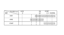
- FIG. 9 shows a power feeding operation to each terminal. Power is fed in the order of the + IGN2 terminal and the + IGN1 terminal by moving the plug from the LOCK position to the ON position. Thereafter, when rotating to the START position, first, power supply to the + IGN2 terminal is stopped, and then power supply to the START terminal is started in addition to the + IGN1 terminal in which the power supply state is maintained.
- the above-described sequence is connected to the power supply terminal, is arranged around the center contact 1 disposed in the center of the terminal base 3, and around the center contact 1, and is connected to the + IGN1 terminal, the + IGN2 terminal, and the START terminal. This is realized by short-circuiting the fixed contact 2 with the movable contact member 7 described above.
- the three fixed contacts 2 are arranged at the terminal positions of the three support portions 22 formed on the terminal base 3 as shown in FIG.
- Each fixed contact 2 is formed in a rectangular shape that intersects with the support portion 22, and the support portion 22 is disposed on two concentric circles with respect to the center of the terminal base 3, and FIGS.
- the corner portion of the contact surface 6 of the movable contact member 7 is supported in a non-contact state with the fixed contact 2.
- the support portion 22 is shown hatched.
- the contact surface 6 of the movable contact member 7 in the state of riding on the support portion 22 is compared with the height of the contact surface 6 with respect to the center contact in the conductive state in which the contact surface 6 shown in FIG. Thus, it is held at a higher position.
- the support portion 22 supports the opposite end of the movable contact member 7 with respect to the contact protrusion 5 in a non-conductive state where the movable contact member 7 does not contact the fixed contact 2, and the movable contact member 7 is horizontal. It functions as a travel path when rotating.
- the central contact 1, the fixed contact 2, and the support portion 22 are formed in a floating island shape that is surrounded by a recess, and wear powder, arc between the fixed contact 2 and between the support portion 22 and the fixed contact 2. Propagation of solidified powder of molten droplets due to electric discharge is regulated.
- the movable contact member 7 When the movable contact member 7 is rotated clockwise in FIG. 4 from the non-conductive state shown in FIGS. 4 and 5, the movable contact member 7 travels on the support portion 22 with the contact portion with the support portion 22 as a sliding portion. Then, it rides on the inclined surface 22a formed at the terminal end of the support portion 22.
- the inclined surface 22a is formed so as to gradually become lower in height, and the movable contact member 7 moved to the inclined surface 22a rotates vertically to the vicinity of the horizontal posture while reducing the vertical rotation angle. As shown in FIG. 6B, landing on the fixed contact 2.
- the contact surface 6 of the movable contact member 7 is V in front view so that the landing to the fixed contact 2 or the movement from the fixed contact 2 to the support portion 22 is performed smoothly. It is formed in a letter shape.
- the movable contact member 7 connected to the + IGN1 terminal where the rotation ranges overlap and the movable contact member 7 connected to the + IGN2 terminal are arranged on the central contact 1. Moves along arcs (AC1, AC2) having different diameters.
- the movable contact member 7 is fitted into a contact mounting groove 23 formed in the rotary operation member 4 as shown in FIGS. 8 (a) to 8 (c).
- the movable contact member 7 fitted in the contact mounting groove 23 has a plate thickness on which the contact protrusion 5 and the contact surface 6 are formed by the compression coil spring 10 inserted into the spring accommodating hole 8 penetrating the contact mounting groove 23. The back surface with respect to the surface is pressed, and a contact pressure with the fixed contact 2 is applied to the movable contact member 7.
- the compression coil spring 10 uses a compression coil spring having a large coil diameter at the center and gradually reducing in diameter toward both ends, so that it can be used in an inverted posture. Further, the coil diameters at both ends are the same.
- the spring constant of the compression coil spring 10 is such that the contact resistance value is sufficiently low so that the contact resistance value with respect to low current conduction is sufficiently low in the state where it is pressed against the fixed contact 2 or the central contact 1 (the state shown in FIG. 8B). And the contact pressure is adjusted to be equal to or lower than the contact pressure at which peeling of the plating film occurs during sliding.
- the spring constant of the compression coil spring 10 having a barrel shape is non-linear because the coil diameter changes, but a deflection region near the central part having a large coil diameter that exhibits linearity is used.
- the inner diameter of the coil at the tip of the compression coil spring 10 is smaller than the plate thickness of the movable contact member 7, and the pressing end against the movable contact member 7 is movable.
- the contact member 7 is held without protruding on the plate thickness surface.
- a mortar portion 11 is formed at the bottom of the spring accommodating hole 8, and the other end (supported end) of the compression coil spring 10 is formed on the bottom 9. ) Is supported.
- the bottom surface 9 is formed in a circular shape having a diameter substantially equal to the outer diameter of the coil at the supported end of the compression coil spring 10.
- the wall surface of the mortar portion 11 is formed by a conical surface that gradually increases in diameter as it goes to the open end, and the upper end, that is, the diameter of the spring accommodating hole 8 is slightly larger than the maximum outer diameter of the compression coil spring 10. It is formed.
- the depth of the mortar portion 11 is as shown in FIG. 8B when the amount of deflection of the compression coil spring 10 is maximized, and the maximum outer diameter portion and the vicinity thereof approach the bottom surface 9.
- the side wall is set so as not to contact the outer periphery of the compression coil spring 10.
- the coil diameter at the end is smaller than the diameter of the spring accommodating hole 8 and serves as a guide at the time of insertion, thereby facilitating the insertion operation.
- the bottom surface 9 of the spring accommodating hole 8 is formed in a circular shape.
- a polygonal shape circumscribing the outer diameter of the coil at the bearing end of the compression coil spring 10 is used.
- the movement of the bearing end can be regulated by the rib tip by protruding a rib or the like from the bottom surface 9 which is larger than the outer diameter to the contact point position between the circumscribed polygon and the coil outer periphery, that is, the apex position of the inscribed polygon. it can.
- the pressed portion by the compression coil spring 10 of the movable contact member 7 is formed by a flat surface.
- the fitting recess 24 into which the pressing end of the compression coil spring 10 is fitted can also be formed.
- the fitting recess 24 can be a linear inclined surface as shown by a chain line in FIG. 10A in addition to the curved conical surface.
Landscapes
- Rotary Switch, Piano Key Switch, And Lever Switch (AREA)
- Contacts (AREA)
Abstract
ロータリースイッチ装置は、中央部接点と固定接点が固定されたターミナルベースと、前記中央部接点周りに回転操作可能な回転操作部材と、板厚面の一面の一端に前記中央部接点に圧接するコンタクト突部を、他端に前記固定接点とのコンタクト面を備えて前記回転操作部材に保持され、前記中央部接点と前記固定接点の間を短絡させる板状の可動接点部材と、一端が前記回転操作部材に形成されるばね収容孔の底面に支承され、他端が前記コンタクト突部、および前記コンタクト面の形成板厚面に対する背向面に圧接して前記コンタクト突部と前記コンタクト面を前記ターミナルベース側に付勢する、たる形の圧縮コイルばねとを有する。
Description
本発明は、ロータリースイッチ装置に関するものである。
特許文献1は、可動接点部材を回転させて固定接点に接触させるロータリースイッチ装置を開示する。特許文献1のロータリースイッチ装置では、絶縁材により形成されるターミナルベースの中心部に円形の第1の固定接点部が露出配置される。第1の固定接点部を囲むように、第2、第3の固定接点部が配置される。
可動接点部材(コンタクトプレート)は、ロータに保持されて円筒コイルばねにより形成されるコンタクトスプリングによりターミナルベース側に付勢されており、固定接点部との接点圧が確保される。
特許文献1のロータリースイッチ装置では、円筒コイルばねを倒伏することなく起立状態に保持するためには、該円筒コイルばねを収容する円筒状の孔が必要となるが、円筒コイルばねの孔への挿入操作は、円筒コイルばねのコイル中心軸を円筒孔の中心に合わせた後、挿入しなければならないために面倒で、とりわけ、自動機による挿入操作が困難であり製造効率が悪い。
本発明の実施例によれば、ロータリースイッチ装置において、圧縮コイルばねの挿入操作性を改善することにより製造効率を向上させる。
本発明の実施例によれば、ロータリースイッチ装置において、
中央部接点1、および固定接点2が固定されたターミナルベース3と、
ターミナルベース3に対して前記中央部接点1周りに回転操作可能な回転操作部材4と、
板厚面の一面の一端に前記中央部接点1に圧接するコンタクト突部5を、他端に固定接点2とのコンタクト面6を備えて前記回転操作部材4に保持され、導通回転位置において前記中央部接点1と固定接点2間を短絡させる板状の可動接点部材7と、
一端が前記回転操作部材4に形成されるばね収容孔8の底面9に支承され、他端が前記可動接点部材7のコンタクト突部5、およびコンタクト面6形成板厚面に対する背向面に圧接してコンタクト突部5、およびコンタクト面6をターミナルベース3側に付勢するたる形の圧縮コイルばね10とを有する。
中央部接点1、および固定接点2が固定されたターミナルベース3と、
ターミナルベース3に対して前記中央部接点1周りに回転操作可能な回転操作部材4と、
板厚面の一面の一端に前記中央部接点1に圧接するコンタクト突部5を、他端に固定接点2とのコンタクト面6を備えて前記回転操作部材4に保持され、導通回転位置において前記中央部接点1と固定接点2間を短絡させる板状の可動接点部材7と、
一端が前記回転操作部材4に形成されるばね収容孔8の底面9に支承され、他端が前記可動接点部材7のコンタクト突部5、およびコンタクト面6形成板厚面に対する背向面に圧接してコンタクト突部5、およびコンタクト面6をターミナルベース3側に付勢するたる形の圧縮コイルばね10とを有する。
本発明において、可動接点部材7を押圧してターミナルベース3上の接点との接触圧を付与する圧縮コイルばね10にはたる形の圧縮コイルばねが使用されており、回転操作部材4のばね収容孔8に挿入される。たる形の圧縮コイルばね10は、先端が縮径され、中央部に行くに従って漸次緩やかに拡径する外形形状を有しているために、ばね収容孔8への装着操作に際し、先端の縮径部のばね収容孔8への導入が簡単で、かつ、傾斜状に導入された際でも、緩やかな外形形状がガイドとなって所定位置に導かれるために、挿入操作が簡単で、自動機による挿入操作も容易になる。
本発明の実施例によれば、前記圧縮コイルばね10の可動接点部材7への押圧端におけるコイル内径が、可動接点部材7の板厚に比して小寸に形成されてもよい。
一般に圧縮コイルばね10による押し付けられた接点間の接触圧は、圧縮コイルばね10の巻数、線径、コイル径等により決定されるばね定数と、撓み量により一義的に決定されるが、可動接点部材7への押圧端のコイル径が可動接点部材7の幅方向寸法、すなわち、板厚に比して大寸である場合には、圧縮コイルばね10の線端が可動接点部材7からはみ出してしまうこととなる。
可動接点部材7から圧縮コイルばね10の線端がはみ出すと、座面が可動接点部材7上に収まる場合に比して、実効的な巻数、あるいは自由長が減少するためにばね定数が変化し、所定の接点圧を得ることができなくなる。しかし、可動接点部材7の線端の座面からのはみ出しが発生するか否かは、圧縮コイルばね10の装着時におけるコイル中心軸線周りの回転角度により決定され、コントロールが不可能であるために、所定の接触圧を確実に確保することが困難となる。
接点圧のばらつきは、接点間の接触抵抗を変化させるために、出力電位のバラつきの原因となる上に、可動接点部材7、あるいは固定接点2部に防食メッキを施して接点の腐食を防止する場合、接点圧の過度の上昇は防食メッキ皮膜の破壊の原因となり、ひいては接点の腐食による接触抵抗の増加をもたらして接触不良の原因ともなる。
可動接点部材7に当接する押圧端の内径を可動接点部材7の板厚に比して少寸とする本発明において、圧縮コイルばね10の座面を可動接点部材7上にはみ出すことなく当接させることができるために、装着状態によりばね定数が変化することがなく、安定した接点間接触圧を与えることが可能になる。
この結果、例えば、可動接点部材7、および固定接点2に防食メッキを施して低接点圧による導電性の確保と、接点の酸化を防止し、酸化膜の除去のための接点間摺接を不要とすることにより、低電流仕様での使用を可能にする場合にも、接点圧が過度に大きくなることによるメッキ皮膜の剥離を確実に防止することが可能になる。
また、たる形の圧縮コイルばね10は、縮径端より大径のコイル部を有しているために、両端をコイル径とする円筒形状のコイルばねに比して縦横比(L/D:但し、Lは自由長、Dはコイル平均径)を小さくすることができるために、作動時の座屈現象が発生しにくい上に、ばね指数(D/d:但し、dは線径)を好適な値に調整して加工性を良好に保つことが可能になる。
本発明の実施例によれば、前記ばね収容孔8の底部には、前記底面9が前記圧縮コイルばね10の被支承端におけるコイル外径とほぼ等径の円形、あるいは前記円形を内接円とする多角形形状をなし、開放端に行くに従って漸次拡開するすり鉢部11が形成されてもよい。
一般に、単一の圧縮コイルばね10により押圧される可動接点部材7には、重心を通る移動方向に押圧力が作用する場合を除いて回転モーメンが発生するために、作用点の位置によりコンタクト突部5、およびコンタクト面6と対応する接点との接触圧が変化する。
また、可動接点部材7のコンタクト突部5、およびコンタクト面6に対応した位置を各々別の圧縮コイルばね10により押圧する場合においても、中央部接点1、あるいは固定接点2からの反力は、圧縮コイルばね10による押圧力の作用線間の距離、各接点からの反力作用線と圧縮コイルばね10による押圧力の作用線間の距離により決定されるために、圧縮コイルばね10の作用線位置が一定しないと、各接点での接触圧のばらつきの原因となる。
本発明において、圧縮コイルばね10の被支承端を支承するばね収容孔8の底面9は、圧縮コイルばね10の被支承端におけるコイル外径とほぼ同一径の円形、あるいは前記円形を内接円とする多角形形状に形成されており、開放端に行くに従って漸次拡径、あるいは拡張されるために、すり鉢部11に導入された圧縮コイルばね10は、コイル中心軸が予め設定された位置に自然に導かれる。
この結果、圧縮コイルばね10の支承位置(基端位置)を正確に管理することが可能となるために、可動接点部材7への付勢力の作用点のズレが発生することがなく、安定した接点間接触圧を与えることが可能になる。
この場合、前記ばね収容孔8は、前記圧縮コイルばね10の最大コイル径部分を拘束して該圧縮コイルばね10の倒伏を規制可能に形成されてもよい。
この場合、圧縮コイルばね10の倒伏を効果的に防止することができるために、可動接点部材7への押圧力の作用位置をより正確に決定することが可能になる。
この場合、圧縮コイルばね10の倒伏を効果的に防止することができるために、可動接点部材7への押圧力の作用位置をより正確に決定することが可能になる。
本発明の実施例によれば、圧縮コイルばねの挿入操作性を改善することにより製造効率を向上させることができる。
図1以下にステアリングロック装置に使用されるイグニッションスイッチとして構成された本発明のロータリースイッチ装置を示す。本例のステアリングロック装置は、ハウジング12内に収容されるシリンダ錠13、シリンダ錠13のプラグ13aの終端に連結されるカム部材14を有し、図外のステアリングコラムに固定される。
ハウジング12にはカム部材14の回転軸に所定角度で交差する方向に進退してステアリングコラム内に突出するロック位置と、ハウジング内に収容されるアンロック位置との間を移動するロックピース15が装着される。ロックピース15は圧縮スプリング15aによりロック位置方向に付勢されており、シリンダ錠13のプラグ13aをロック回転位置から回転操作すると、ステアリングシャフトに係止するロック位置から係止解除されるアンロック位置に移動し、ステアリングシャフトの操作が可能になる。
また、上記ハウジング12には、プラグ13aの回転に伴って所定の端子間を導通させ、車両の電装系への給電状態を変更するイグニッションスイッチが連結される。プラグ13aの回転操作をイグニッションスイッチに伝達するために、ハウジング12には、上記カム部材14に噛合してカム部材14とともに回転する連結バー16が配置される。
図2に示すように、イグニッションスイッチは、平面視円形のターミナルベース3を備えたスイッチケース17と、スイッチケース17に対して上記ターミナルベース3の中心周りに回転自在な回転操作部材4と、スイッチケース17に連結されて回転操作部材4を覆うスイッチカバー18とを有し、絶縁材料により形成されるターミナルベース3には中央部接点1と固定接点2とが回転操作部材4との回転境界面に露出した状態で配置される。
上記中央部接点1、および各固定接点2は、配線を経由してスイッチケース17内に引き出される。
回転操作部材4は絶縁材料により形成され、一端部に上記連結バー16との連結孔4aが形成される。この回転操作部材4は、トーションスプリング19により後述するSTART位置からON位置に戻るときのみ付勢され、クリックスプリング20により付勢されるクリックボール21をスイッチカバー18内壁の溝にはめることにより適切な接続操作角で節度回転する。
さらに回転操作部材4には、所定板厚を有する板状の可動接点部材7が板厚面をターミナルベース3に向けて保持される。この可動接点部材7は、図7(a)および図7(b)に示すように、板厚面の一端にV字突起形状のコンタクト突部5を、他端に平板状のコンタクト面6を有しており、コンタクト突部5の先端には後述する中央部接点1に圧接した際に接触状態を良好に保つためにアール面取りが形成される。
以上のように形成される可動接点部材7は、後述する各固定接点2に対応して3枚使用され、これら可動接点部材7、および各固定接点2の表面には、高い接点圧力によるセルフクリーニング作用を要することなく接触面での腐食発生を防止してコンタクト信頼性を高めるために、防食用導電加工としての銀メッキが施される。
以上の各可動接点部材7は、回転操作部材4に保持されて、図1における回転軸(RA)に沿う方向に移動自在であり、後述するように、圧縮コイルばね10によりコンタクト突部5、およびコンタクト面6の背面を押圧するによりターミナルベース3の表面側に付勢される。
本例によるイグニッションスイッチは、プラグ13aをLOCK、ON、START位置の順で回転操作した際に、+IGN1、+IGN2、およびSTARTの3個の出力端子に電源端子から入力された電源電圧を出力するように形成される。図9は各端子への給電動作を示すもので、プラグのLOCK位置からON位置への移動によって+IGN2端子、+IGN1端子の順で給電される。この後、START位置まで回転させると、まず、+IGN2端子への給電が停止された後、給電状態が維持された+IGN1端子に加えてSTART端子への給電が開始される。
上述したシーケンスは、電源端子に接続され、ターミナルベース3の中心部に配置される中央部接点1と、中央部接点1の周りに配置され、+IGN1端子、+IGN2端子、およびSTART端子に接続される固定接点2とを上述した可動接点部材7により短絡させることにより実現される。
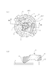
以上の3個の固定接点2は、図3に示すように、ターミナルベース3に形成される3個の支承部22の終端位置に各々配置される。各固定接点2は、支承部22に交差する矩形形状に形成されるとともに、支承部22は、ターミナルベース3の中心に対する2個の同心円上に配置されており、図5(a)および図5(b)に示すように、固定接点2との非接触状態において、可動接点部材7のコンタクト面6の隅角部を支承する。なお、図3において支承部22はハッチングを施して示される。
支承部22に乗り上げた状態で可動接点部材7のコンタクト面6は、図6(b)に示すコンタクト面6が固定接点2上に乗り上げた導通状態におけるコンタクト面6の中央接点に対する高さに比して、さらに高い位置に保持される。
以上のように、上記支承部22は、可動接点部材7が固定接点2上に接触しない非導通状態において、可動接点部材7のコンタクト突部5に対する反対端を支承し、可動接点部材7が水平回転操作される際の走行路として機能する。
さらに、上記中央部接点1、固定接点2、および支承部22は、周囲が凹部に囲まれた浮島状に形成され、固定接点2間、支承部22と固定接点2間での磨耗粉、アーク放電による溶融飛沫の凝固粉の伝搬が規制される。
図4、5に示す非導通状態から可動接点部材7を図4において時計回りに回転操作すると、可動接点部材7は、支承部22との接触部を摺動部として支承部22上を走行した後、支承部22の終端に形成された傾斜面22aに乗り上げる。傾斜面22aは、漸次低背となるように形成されており、傾斜面22aに移動した可動接点部材7は、垂直回転角度を小さくしながら水平姿勢近傍まで垂直回転し、図6(a)および図6(b)に示すように、固定接点2上にランディングする。
固定接点2へのランディング、あるいは固定接点2から支承部22への移動が円滑に行われるように、可動接点部材7のコンタクト面6は、図7(b)に示すように、正面視においてV字形状に形成される。
また、中央部接点1における可動接点部材7の摺動軌跡は、相互に重なると、重なった部位での摩耗機会が増加する。これを防止するために、図6(a)において鎖線で示すように、回転範囲が重なりあう+IGN1端子に断接する可動接点部材7と、+IGN2端子に断接する可動接点部材7は中央部接点1上で径の異なった円弧(AC1、AC2)に沿って移動する。
上記可動接点部材7は、図8(a)から図8(c)に示すように、回転操作部材4に形成された接点装着溝23に嵌合される。接点装着溝23に嵌合された可動接点部材7は、接点装着溝23を貫通するばね収容孔8に挿入される圧縮コイルばね10によりコンタクト突部5、およびコンタクト面6が形成される板厚面に対する背向面が押圧され、可動接点部材7に固定接点2との接触圧を付与する。
圧縮コイルばね10は、図8(a)に示すように、中央部におけるコイル径が大きく、両端に行くに従って漸次縮径されるたる形の圧縮コイルばねが使用され、反転姿勢で使用可能なように、両端におけるコイル径が同一とされる。
圧縮コイルばね10のばね定数は、固定接点2、あるいは中央部接点1に圧接した状態(図8(b)の状態)で、低電流の導通に対する接触抵抗値が十分低くなるに十分な接点圧を超え、かつ、摺動時のメッキ皮膜の剥離が発生する接点圧以下となるように調整される。
また、たる形の圧縮コイルばね10のばね定数は、コイル径が変化することから非線型となるが、概ね線型性を発揮するコイル径の大きな中央部近傍の撓み領域が使用される。
この圧縮コイルばね10の先端部におけるコイル内径は、図7(a)に示すように、可動接点部材7の板厚に比して小径に形成されており、可動接点部材7に対する押圧端は可動接点部材7の板厚面上にはみ出すことなく保持される。
この結果、可動接点部材7を押圧する際に、押圧端の線端が可動接点の板厚面からはみ出すことによる実効巻数の損失等、ばね定数を変化させる要因が排除される。
図8(a)から図8(c)に示すように、上記ばね収容孔8の底部にはすり鉢部11が形成されており、底面9において圧縮コイルばね10の他方の端部(被支承端)が支承される。底面9は圧縮コイルばね10の被支承端におけるコイル外径にほぼ等しい径の円形形状に形成される。
また、すり鉢部11の壁面は開放端に行くに従って漸次拡径する円錐面により形成されており、上端、すなわち、ばね収容孔8の径は、圧縮コイルばね10の最大外径よりやや大径に形成される。
さらに、すり鉢部11の深さは、図8(b)に示すように、圧縮コイルばね10の撓み量が最大となって、最大外径部、およびその近傍領域が底面9に接近してきた際に側壁が圧縮コイルばね10の外周に接触しない程度に設定される。
したがって本例において、ばね収容孔8に圧縮コイルばね10を挿入すると、すり鉢部11の側壁によりガイドされるようにして、被支承端は、予め設定したばね収容孔8の中心位置に導かれる。この状態で最大径部の横方向への移動はばね収容孔8の側壁により規制されるために、過度の傾きが防止される。
この結果、圧縮コイルばね10の可動接点部材7への当接部と、回転操作部材4への支承端の位置が一定するために、圧縮コイルばね10の撓み量、すなわち、付勢力の大きさを正確に管理することができる。
本例において、圧縮コイルばね10による押圧力は、可動接点部材7のコンタクト突部5とコンタクト面6に対応する2箇所に与えられているために、各々の圧縮コイルばね10による押圧力の作用位置が変動すると、中央部接点1、および固定接点2との接触圧の分配が変動し、一方に過度な接触圧が発生してメッキ皮膜の剥離を招来したり、過少な接触圧による導通不良等を招来する虞がある。
これに対し、本例においては、可動接点部材7に対する荷重点、荷重の大きさが一定しているために、接点において予め設定した接触圧を得ることができる。
また、圧縮コイルばね10をばね収容孔8に挿入する場合、端部のコイル径がばね収容孔8の径に比して小さく、挿入時のガイドとなるために、挿入作業も容易になる。
なお、以上においては、ばね収容孔8の底面9を円形に形成する場合を示したが、この他に、圧縮コイルばね10の支承端におけるコイル外径に外接する多角形形状としたり、あるいはコイル外径に比して大きな底面9から外接多角形とコイル外周との接触点位置、すなわち、内接多角形の頂点位置にリブ等を突出させてリブ先端により支承端の移動を規制することができる。
また、以上においては、可動接点部材7の圧縮コイルばね10による被押圧部は平面により形成される場合を示したが。図10(a)から図10(c)に示すように、圧縮コイルばね10の押圧端を嵌合させる嵌合凹部24を形成することもできる。この場合、嵌合凹部24は、湾曲状の錐面とする以外に、図10(a)において鎖線で示すように、直線状の傾斜面とすることもできる。
1 中央部接点
2 固定接点
3 ターミナルベース
4 回転操作部材
5 コンタクト突部
6 コンタクト面
7 可動接点部材
8 ばね収容孔
9 底面
10 圧縮コイルばね
11 すり鉢部
2 固定接点
3 ターミナルベース
4 回転操作部材
5 コンタクト突部
6 コンタクト面
7 可動接点部材
8 ばね収容孔
9 底面
10 圧縮コイルばね
11 すり鉢部
Claims (4)
- 中央部接点、および固定接点が固定されたターミナルベースと、
前記ターミナルベースに対して前記中央部接点周りに回転操作可能な回転操作部材と、
板厚面の一面の一端に前記中央部接点に圧接するコンタクト突部を、他端に前記固定接点とのコンタクト面を備えて前記回転操作部材に保持され、導通回転位置において前記中央部接点と前記固定接点の間を短絡させる板状の可動接点部材と、
一端が前記回転操作部材に形成されるばね収容孔の底面に支承され、他端が前記可動接点部材の前記コンタクト突部、および前記コンタクト面の形成板厚面に対する背向面に圧接して前記コンタクト突部、および前記コンタクト面を前記ターミナルベース側に付勢する、たる形の圧縮コイルばねとを有する、ロータリースイッチ装置。 - 前記圧縮コイルばねの前記可動接点部材への押圧端におけるコイル内径が、前記可動接点部材の板厚に比して小寸に形成される、請求項1記載の前記ロータリースイッチ装置。
- 前記ばね収容孔の底部には、前記底面が前記圧縮コイルばねの被支承端におけるコイル外径とほぼ等径の円形、あるいは前記円形を内接円とする多角形形状をなし、開放端に行くに従って漸次拡開するすり鉢部が形成される、請求項1または2記載の前記ロータリースイッチ装置。
- 前記ばね収容孔は、前記圧縮コイルばねの最大コイル径部分を拘束して該圧縮コイルばねの倒伏を規制可能に形成される、請求項3記載の前記ロータリースイッチ装置。
Priority Applications (4)
| Application Number | Priority Date | Filing Date | Title |
|---|---|---|---|
| KR1020187032818A KR20190008857A (ko) | 2016-05-17 | 2017-05-16 | 로터리 스위치 장치 |
| EP17799388.8A EP3460820B1 (en) | 2016-05-17 | 2017-05-16 | Rotary switch device |
| CN201780030463.4A CN109155215B (zh) | 2016-05-17 | 2017-05-16 | 旋转开关装置 |
| US16/176,149 US10790104B2 (en) | 2016-05-17 | 2018-10-31 | Rotary switch device |
Applications Claiming Priority (2)
| Application Number | Priority Date | Filing Date | Title |
|---|---|---|---|
| JP2016099040A JP6676465B2 (ja) | 2016-05-17 | 2016-05-17 | ロータリースイッチ装置 |
| JP2016-099040 | 2016-05-17 |
Related Child Applications (1)
| Application Number | Title | Priority Date | Filing Date |
|---|---|---|---|
| US16/176,149 Continuation US10790104B2 (en) | 2016-05-17 | 2018-10-31 | Rotary switch device |
Publications (1)
| Publication Number | Publication Date |
|---|---|
| WO2017199964A1 true WO2017199964A1 (ja) | 2017-11-23 |
Family
ID=60325373
Family Applications (1)
| Application Number | Title | Priority Date | Filing Date |
|---|---|---|---|
| PCT/JP2017/018385 Ceased WO2017199964A1 (ja) | 2016-05-17 | 2017-05-16 | ロータリースイッチ装置 |
Country Status (6)
| Country | Link |
|---|---|
| US (1) | US10790104B2 (ja) |
| EP (1) | EP3460820B1 (ja) |
| JP (1) | JP6676465B2 (ja) |
| KR (1) | KR20190008857A (ja) |
| CN (1) | CN109155215B (ja) |
| WO (1) | WO2017199964A1 (ja) |
Families Citing this family (8)
| Publication number | Priority date | Publication date | Assignee | Title |
|---|---|---|---|---|
| USD734277S1 (en) | 2013-11-15 | 2015-07-14 | Lutron Electronics Co., Inc. | Control device |
| USD813828S1 (en) | 2014-09-16 | 2018-03-27 | Lutron Electronics Co., Inc. | Control device |
| JP6774219B2 (ja) * | 2016-05-17 | 2020-10-21 | 株式会社アルファ | ロータリースイッチ装置 |
| JP6655470B2 (ja) * | 2016-05-17 | 2020-02-26 | 株式会社アルファ | ロータリースイッチ装置 |
| USD907585S1 (en) * | 2019-02-26 | 2021-01-12 | Nio Nextev Limited | Rotary switch |
| KR102166795B1 (ko) * | 2019-04-12 | 2020-10-16 | 전영환 | 터치 스위치 |
| JP7566494B2 (ja) * | 2020-05-28 | 2024-10-15 | 株式会社日本マイクロニクス | 電気的接触子及び電気的接触子の製造方法 |
| USD967781S1 (en) | 2021-03-11 | 2022-10-25 | Lutron Technology Company Llc | Control device |
Citations (4)
| Publication number | Priority date | Publication date | Assignee | Title |
|---|---|---|---|---|
| JPH02129479A (ja) * | 1988-11-09 | 1990-05-17 | Aisin Aw Co Ltd | 圧力調整弁 |
| JPH08115640A (ja) * | 1994-08-22 | 1996-05-07 | Toyo Denso Co Ltd | スイッチ装置 |
| CN1861964A (zh) * | 2006-04-30 | 2006-11-15 | 陈志和 | 一种高保险三排弹子配保险梳的平板匙锁头及钥匙 |
| JP2015103495A (ja) | 2013-11-28 | 2015-06-04 | 株式会社ユーシン | イグニッションスイッチ |
Family Cites Families (18)
| Publication number | Priority date | Publication date | Assignee | Title |
|---|---|---|---|---|
| US2666101A (en) * | 1951-03-02 | 1954-01-12 | Carter Parts Company | Sliding contactor switch construction |
| US3602656A (en) * | 1970-03-02 | 1971-08-31 | Gen Motors Corp | Electrical switch |
| US3803370A (en) * | 1973-02-21 | 1974-04-09 | Grayhill | Miniature multi-position rotary switch with flexible contact arrangements and inner housing cylindrical sleeve |
| GB1495215A (en) * | 1975-02-17 | 1977-12-14 | Murata Manufacturing Co | Electric switch assembly |
| DE3141550C2 (de) * | 1981-10-20 | 1983-12-01 | Standard Elektrik Lorenz Ag, 7000 Stuttgart | Miniatur-Stufendrehschalter |
| US4748297A (en) * | 1986-07-11 | 1988-05-31 | Carlingswitch, Inc. | Rotary switch |
| US4803314A (en) * | 1986-12-22 | 1989-02-07 | Carlingswitch, Inc. | Momentary rotary switch |
| IT214255Z2 (it) * | 1988-04-13 | 1990-04-24 | Turatti Mario | Commutatore di accesione ed avviamento a contatti frontali striscianti per autoveicoli |
| JPH07245040A (ja) * | 1994-03-01 | 1995-09-19 | Kansei Corp | 回転式スイッチ |
| US5679937A (en) * | 1994-08-22 | 1997-10-21 | Toyodenso Kabushiki Kaisha | Switching device |
| JPH08245040A (ja) | 1995-03-15 | 1996-09-24 | Toshiba Corp | 紙幣集積装置、紙幣重なり検出搬送装置及び紙幣枚数カウンタ |
| EP0757366A2 (en) * | 1995-08-03 | 1997-02-05 | UNITED TECHNOLOGIES AUTOMOTIVE, Inc. | Electrical roller contactor |
| CN2274706Y (zh) * | 1996-06-07 | 1998-02-18 | 王涌铠 | 自填充密封件 |
| EP2233329B1 (en) * | 2001-04-13 | 2015-08-26 | Mitsubishi Steel MFG. CO., LTD. | Suspension coil spring |
| JP4430556B2 (ja) * | 2005-01-31 | 2010-03-10 | 株式会社ホンダロック | ロータリースイッチ装置 |
| US7605334B2 (en) | 2005-01-31 | 2009-10-20 | Kabushiki Kaisha Honda Lock | Rotary switch device |
| JP5280511B2 (ja) | 2011-09-05 | 2013-09-04 | 株式会社島野製作所 | 接触端子 |
| CN204647102U (zh) * | 2015-01-22 | 2015-09-16 | 台州德尔福汽车部件有限公司 | Ocv阀的换向杆复位弹簧安装结构 |
-
2016
- 2016-05-17 JP JP2016099040A patent/JP6676465B2/ja active Active
-
2017
- 2017-05-16 EP EP17799388.8A patent/EP3460820B1/en active Active
- 2017-05-16 WO PCT/JP2017/018385 patent/WO2017199964A1/ja not_active Ceased
- 2017-05-16 KR KR1020187032818A patent/KR20190008857A/ko not_active Ceased
- 2017-05-16 CN CN201780030463.4A patent/CN109155215B/zh active Active
-
2018
- 2018-10-31 US US16/176,149 patent/US10790104B2/en active Active
Patent Citations (4)
| Publication number | Priority date | Publication date | Assignee | Title |
|---|---|---|---|---|
| JPH02129479A (ja) * | 1988-11-09 | 1990-05-17 | Aisin Aw Co Ltd | 圧力調整弁 |
| JPH08115640A (ja) * | 1994-08-22 | 1996-05-07 | Toyo Denso Co Ltd | スイッチ装置 |
| CN1861964A (zh) * | 2006-04-30 | 2006-11-15 | 陈志和 | 一种高保险三排弹子配保险梳的平板匙锁头及钥匙 |
| JP2015103495A (ja) | 2013-11-28 | 2015-06-04 | 株式会社ユーシン | イグニッションスイッチ |
Non-Patent Citations (1)
| Title |
|---|
| See also references of EP3460820A4 |
Also Published As
| Publication number | Publication date |
|---|---|
| US10790104B2 (en) | 2020-09-29 |
| JP2017208201A (ja) | 2017-11-24 |
| CN109155215B (zh) | 2021-01-15 |
| EP3460820A1 (en) | 2019-03-27 |
| KR20190008857A (ko) | 2019-01-25 |
| US20190066948A1 (en) | 2019-02-28 |
| EP3460820B1 (en) | 2021-01-27 |
| JP6676465B2 (ja) | 2020-04-08 |
| CN109155215A (zh) | 2019-01-04 |
| EP3460820A4 (en) | 2020-01-08 |
Similar Documents
| Publication | Publication Date | Title |
|---|---|---|
| JP2017208201A (ja) | ロータリースイッチ装置 | |
| TWI434467B (zh) | 電連接器 | |
| US8834183B2 (en) | Housingless connector | |
| US9680252B2 (en) | Connector pair including a connector having a face portion and a magnetic portion | |
| WO2013035399A1 (ja) | 接触端子 | |
| JP5571837B1 (ja) | 電気コネクタ | |
| CN102326299A (zh) | 同轴连接器 | |
| EP3136412B1 (en) | Rotary switch device | |
| US20180034203A1 (en) | Connector | |
| TWM336597U (en) | Electrical connector | |
| EP4207504B1 (en) | Connector | |
| JP6154217B2 (ja) | メス端子 | |
| JP2013222579A (ja) | コネクタ | |
| JP2017130426A (ja) | コネクタ及びコネクタ装置 | |
| JP6655470B2 (ja) | ロータリースイッチ装置 | |
| US9653855B2 (en) | Connector and connector unit | |
| US20220416462A1 (en) | Spring connector | |
| US10566152B2 (en) | Rotary switch device | |
| US10650990B2 (en) | Rotary switch | |
| JP2016166742A (ja) | 液面検出装置 | |
| US20050287863A1 (en) | Insulation piercing contact alignment system | |
| KR102234676B1 (ko) | 고전압 릴레이 장치 | |
| KR102234677B1 (ko) | 고전압 릴레이 장치 | |
| JP2018045764A (ja) | 電気コネクタ | |
| JP2018067461A (ja) | 端子装置及びそれを備えた配線器具 |
Legal Events
| Date | Code | Title | Description |
|---|---|---|---|
| ENP | Entry into the national phase |
Ref document number: 20187032818 Country of ref document: KR Kind code of ref document: A |
|
| NENP | Non-entry into the national phase |
Ref country code: DE |
|
| 121 | Ep: the epo has been informed by wipo that ep was designated in this application |
Ref document number: 17799388 Country of ref document: EP Kind code of ref document: A1 |
|
| ENP | Entry into the national phase |
Ref document number: 2017799388 Country of ref document: EP Effective date: 20181217 |