WO2017204117A1 - 流体計測装置 - Google Patents
流体計測装置 Download PDFInfo
- Publication number
- WO2017204117A1 WO2017204117A1 PCT/JP2017/018893 JP2017018893W WO2017204117A1 WO 2017204117 A1 WO2017204117 A1 WO 2017204117A1 JP 2017018893 W JP2017018893 W JP 2017018893W WO 2017204117 A1 WO2017204117 A1 WO 2017204117A1
- Authority
- WO
- WIPO (PCT)
- Prior art keywords
- flow velocity
- fluid
- propagation time
- ultrasonic
- unit
- Prior art date
- Legal status (The legal status is an assumption and is not a legal conclusion. Google has not performed a legal analysis and makes no representation as to the accuracy of the status listed.)
- Ceased
Links
Images



Classifications
-
- G—PHYSICS
- G01—MEASURING; TESTING
- G01F—MEASURING VOLUME, VOLUME FLOW, MASS FLOW OR LIQUID LEVEL; METERING BY VOLUME
- G01F1/00—Measuring the volume flow or mass flow of fluid or fluent solid material wherein the fluid passes through a meter in a continuous flow
- G01F1/66—Measuring the volume flow or mass flow of fluid or fluent solid material wherein the fluid passes through a meter in a continuous flow by measuring frequency, phase shift or propagation time of electromagnetic or other waves, e.g. using ultrasonic flowmeters
- G01F1/667—Arrangements of transducers for ultrasonic flowmeters; Circuits for operating ultrasonic flowmeters
- G01F1/668—Compensating or correcting for variations in velocity of sound
-
- G—PHYSICS
- G01—MEASURING; TESTING
- G01F—MEASURING VOLUME, VOLUME FLOW, MASS FLOW OR LIQUID LEVEL; METERING BY VOLUME
- G01F1/00—Measuring the volume flow or mass flow of fluid or fluent solid material wherein the fluid passes through a meter in a continuous flow
- G01F1/66—Measuring the volume flow or mass flow of fluid or fluent solid material wherein the fluid passes through a meter in a continuous flow by measuring frequency, phase shift or propagation time of electromagnetic or other waves, e.g. using ultrasonic flowmeters
-
- G—PHYSICS
- G01—MEASURING; TESTING
- G01P—MEASURING LINEAR OR ANGULAR SPEED, ACCELERATION, DECELERATION, OR SHOCK; INDICATING PRESENCE, ABSENCE, OR DIRECTION, OF MOVEMENT
- G01P5/00—Measuring speed of fluids, e.g. of air stream; Measuring speed of bodies relative to fluids, e.g. of ship, of aircraft
- G01P5/24—Measuring speed of fluids, e.g. of air stream; Measuring speed of bodies relative to fluids, e.g. of ship, of aircraft by measuring the direct influence of the streaming fluid on the properties of a detecting acoustical wave
- G01P5/245—Measuring speed of fluids, e.g. of air stream; Measuring speed of bodies relative to fluids, e.g. of ship, of aircraft by measuring the direct influence of the streaming fluid on the properties of a detecting acoustical wave by measuring transit time of acoustical waves
Definitions
- the present invention relates to a fluid measurement device that measures the flow velocity and flow rate of a fluid using ultrasonic waves.
- a propagation time difference method is known as a method for measuring the flow velocity and flow rate of a fluid using ultrasonic waves (see, for example, Patent Document 1).
- This method utilizes a phenomenon in which ultrasonic waves are transmitted and received in a direction along the flow and in a direction against the flow with respect to the flow of the fluid, and the difference in the propagation time of the ultrasonic waves in the two directions changes depending on the flow velocity of the fluid.
- Patent Document 1 discloses a technique for improving the S / N ratio (signal to noise ratio) by performing transmission and reception of ultrasonic waves a plurality of times and performing synchronous addition averaging of measured waveforms. It is disclosed.
- the speed of sound of ultrasonic waves is not constant, but changes under the influence of other physical quantities such as temperature. Therefore, if the S / N ratio is improved by measuring the propagation time of the ultrasonic wave to the fluid multiple times by the propagation time difference method, the measurement error will be affected by the temperature change for the longer measurement time. There is a growing problem.
- the present invention has been made in view of such problems, and an object of the present invention is to provide a fluid measuring device that can accurately measure the flow velocity of a fluid even when the speed of sound in the fluid changes. It is to provide.
- the fluid measurement device of the present invention includes at least a pair of ultrasonic transmission / reception means for transmitting / receiving ultrasonic waves to a fluid flowing in a pipe, a time measurement unit for measuring a propagation time of ultrasonic waves transmitted / received by the ultrasonic transmission / reception means, A flow velocity measurement unit that obtains the flow velocity of the fluid from the ultrasonic propagation time measured by the time measurement unit, wherein one of the pair of ultrasonic transmission / reception means is arranged upstream of the pipe and the other is arranged downstream of the pipe.
- the flow velocity Va and the flow velocity Vb are measured by changing the measurement order of the propagation time.
- the sign of the error that occurs and the error that occurs in the flow velocity Vb can be reversed. Therefore, since the error can be canceled by using the flow velocity Va and the flow velocity Vb, the ultrasonic wave propagation time can be measured a plurality of times to improve the S / N ratio, and the fluid flow velocity can be accurately measured.
- the flow velocity of the fluid can be accurately measured.
- FIG. 1 is a schematic configuration diagram of a fluid measuring device according to an embodiment.
- the fluid measuring device 1 measures the flow velocity of the fluid 102 flowing in the pipe 100 using ultrasonic waves.
- a pair of ultrasonic probes 10 a and 10 b as a pair of ultrasonic transmission / reception means is disposed so as to face the flow of the fluid 102 in an oblique direction.
- the ultrasonic probe 10a is disposed on the upstream side with respect to the flow of the fluid 102 in the pipe 100, and the ultrasonic probe 10b is disposed on the downstream side.
- the ultrasonic probes 10a and 10b include wedges 12a and 12b attached to the pipe 100, respectively, and ultrasonic transducers 11a and 11b that apply ultrasonic waves to the wedges 12a and 12b.
- the ultrasonic transducer 11a is connected to the transmission unit 31 and the reception unit 32 via the switch unit 33a
- the ultrasonic transducer 11b is connected to the transmission unit 31 and the reception unit 32 via the switch unit 33b.
- the switch units 33a and 33b switch the connection destination of the ultrasonic probes 10a and 10b to the transmission unit 31 or the reception unit 32, and switch the pair of ultrasonic probes 10a and 10b for transmission or reception.
- the transmission unit 31 is connected to the time measurement unit 34, and outputs drive signals to the ultrasonic transducers 11a and 11b in response to instructions from the time measurement unit 34.
- the receiving unit 32 is connected to the time measuring unit 34, and outputs the electric signal input to the ultrasonic transducers 11 a and 11 b to the time measuring unit 34.
- the time measurement unit 34 measures the propagation time from when the drive signal is output from the transmission unit 31 to when the electrical signal is input from the reception unit 32.
- the switch units 33a and 33b are respectively connected to the control unit 35. The switches 33a and 33b are switched by a signal from the control unit 35, and the transmission / reception relationships of the ultrasonic probes 10a and 10b are reversed.
- a drive signal (current) corresponding to the waveform of the ultrasonic wave is applied from the transmission unit 31 via the switch unit 33 a to the ultrasonic transducer 11 a to generate ultrasonic waves.
- the ultrasonic wave passes through the wedge 12a and the wall surface 101, and enters the fluid 102 in the pipe 100 at a predetermined angle ⁇ .
- the ultrasonic wave incident on the pipe 100 is propagated along the flow of the fluid 102 to the ultrasonic probe 10b facing the ultrasonic probe 10a.
- the ultrasonic wave propagated to the ultrasonic probe 10b is converted into an electric signal by the ultrasonic transducer 11b and input to the receiving unit 32 via the switch 33b.
- the time measuring unit 34 measures the propagation time Tf of the ultrasonic wave from the upstream ultrasonic probe 10a toward the downstream ultrasonic probe 10b.
- a drive signal is applied from the transmission unit 31 to the ultrasonic transducer 11b via the switch unit 33b to generate ultrasonic waves.
- the ultrasonic wave passes through the wedge 12b and the wall surface 101, enters the fluid 102 in the pipe 100 at a predetermined angle ⁇ , and is transmitted to the ultrasonic probe 10a.
- the ultrasonic wave input to the ultrasonic transducer 11a is converted into an electric signal and input to the receiving unit 32 via the switch 33a.
- the time measurement unit 34 measures the propagation time Tr of the ultrasonic wave from the downstream ultrasonic probe 10b to the upstream ultrasonic probe 10a.
- the flow rate measuring unit 36 is connected to the time measuring unit 34 via the control unit 35, and the flow rate measuring unit 37 is connected to the flow rate measuring unit 36.
- the flow rate measuring unit 36 calculates the flow rate of the fluid 102 from the ultrasonic propagation times Tf and Tr, and the flow rate measuring unit 37 calculates the flow rate of the fluid 102 from the flow rate of the fluid 102 obtained by the flow rate measuring unit 36.
- the flow rate of the fluid 102 obtained by the flow velocity measuring unit 36 may be removed from a high frequency component by performing, for example, a damping process described later in a removal processing unit (not shown). Thereby, a measurement result can be stabilized and the error in the measurement result of the flow velocity of the fluid 102 can be reduced.
- the time measuring unit 34, the control unit 35, the flow velocity measuring unit 36, and the flow rate measuring unit 37 are configured by a processor, a memory, and the like that execute various processes.
- the memory is composed of one or a plurality of storage media such as a ROM (Read Only Memory) and a RAM (Random Access Memory) depending on the application.
- the time measuring unit 34 may be composed of a time measuring circuit, a time measuring device, a time measuring device, and the like.
- the control unit 35 may include a control circuit, a controller, a control device, and the like.
- the flow velocity measuring unit 36 may be composed of a flow velocity measuring circuit, a flow velocity measuring device, a flow velocity measuring device, and the like.
- the flow rate measurement unit 37 may be configured with a flow rate measurement circuit, a flow rate measurement device, a flow rate measurement device, and the like.
- equation (3) is shown when the flow velocity V of the fluid 102 is solved.
- V L / 2 cos ⁇ ⁇ ((1 / Tf) ⁇ (1 / Tr)) (3)
- the flow rate Q of the fluid is expressed as in Expression (4) using the flow velocity V of the fluid 102 and the cross-sectional area A of the pipe 100.
- Q V ⁇ A (4)
- the cross-sectional area A of the pipe 100 is expressed by the equation (5) using the inner diameter D of the pipe 100.
- A (D / 2) 2 ⁇ ⁇ (5)
- the measurement of the propagation time Tf or Tr is continuously performed a plurality of times, and the S / N ratio can be improved by synchronously averaging the measured waveforms, thereby improving the measurement accuracy.
- the flow velocity V of the fluid 102 expressed by the equations (1) to (3) is based on the assumption that the sound velocity C of the fluid 102 is constant. Actually, it is known that the speed of sound C of the fluid 102 changes depending on the temperature of the fluid 102, for example.
- the propagation time Tr ′ when the sound speed of the fluid 102 when measuring the propagation time Tr ′ in consideration of the change in sound speed is changed to C + ⁇ C with respect to the sound speed C of the fluid 102 when the propagation time Tf is measured, the propagation time Tr ′. Is expressed as in equation (6).
- Tr ′ L / (C + ⁇ C ⁇ V cos ⁇ ) (6)
- an error occurs in the flow velocity V ′ of the fluid 102 by ⁇ ( ⁇ C / 2 cos ⁇ ).
- the flow velocity measurement unit 36 obtains the flow velocity Va of the fluid 102 obtained by measuring the propagation time Tr next to the propagation time Tf and the propagation time Tf obtained after the propagation time Tr. The measurement error is canceled using the flow velocity Vb of the fluid 102.
- the time measurement unit 34 first measures the propagation time Tf1. Next, the control unit 35 switches the switch units 33a and 33b, and then the time measurement unit 34 measures the propagation time Tr1. Subsequently, the time measurement unit 34 measures the propagation time Tr2. The control unit 35 switches the switch units 33a and 33b again, and the time measurement unit 34 measures the propagation time Tf2. The propagation times Tf1, Tr1, Tr2, and Tf2 are input to the flow velocity measuring unit 36, and the time measuring unit 34 calculates the flow velocity V of the fluid 102.
- Tf1 L / (C + V cos ⁇ ) (12)
- Tr1 L / (C + ⁇ C ⁇ Vcos ⁇ ) (13)
- Tr2 L / (C + 2 ⁇ C ⁇ Vcos ⁇ ) (14)
- Tf2 L / (C + 3 ⁇ C + Vcos ⁇ ) (15)
- the flow velocity of the fluid 102 obtained from the propagation times Tf1 and Tr1 is Va
- the flow velocity of the fluid 102 obtained from the propagation times Tr2 and Tf1 is Vb
- the flow rates Va and Vb of the fluid 102 are obtained from equations (12) to (15).
- equations (16) and (17) are shown.
- the time measuring unit 34 changes the measurement order of the propagation times Tf and Tr to measure the propagation time, and the flow velocity measuring unit 36 obtains the flow velocity Va and the flow velocity Vb of the fluid 102 to obtain an error.
- the flow rate measurement unit 37 uses the flow velocity V of the fluid 102 calculated by the flow velocity measurement unit 36 to calculate the flow rate Q of the fluid 102 from the above equation (4).
- the time measurement unit 34 alternately measures the propagation time as Tf1, Tr1, Tf2, Tr2,...
- the flow velocity measurement unit 36 performs the propagation time.
- the flow velocity Va of the fluid 102 may be obtained from Tf1 and Tr1
- the flow velocity Vb of the fluid 102 may be obtained from the propagation times Tr1 and Tf2.
- the propagation times Tf1, Tr1, Tf2 are as shown in equations (19) to (21). Indicated.
- Tf1 L / (C + V cos ⁇ ) (19)
- Tr1 L / (C + ⁇ C ⁇ Vcos ⁇ ) (20)
- Tf2 L / (C + 2 ⁇ C + Vcos ⁇ ) (21)
- the flow velocity Va of the fluid 102 is obtained from the propagation times Tf2 and Tr2, and the flow velocity of the fluid 102 is calculated from the propagation times Tr2 and Tf3 (the propagation time for ultrasonic waves to propagate from the third upstream to the downstream ultrasonic probe).
- Vb the flow velocity V of the fluid 102 can be continuously measured with high accuracy.
- the propagation time Tf is continuously measured a plurality of times
- the propagation time Tr is continuously measured a plurality of times, thereby improving the S / N ratio and improving the measurement accuracy.
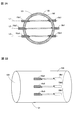
- FIG. 3 is a diagram showing a plurality of pairs of ultrasonic transmission / reception means according to the embodiment.
- 3A is a cross-sectional view of the piping
- FIG. 3B is a side view of the piping.
- the fluid measuring apparatus 1 measures ultrasonic propagation times Tr and Tf along three measurement lines L1, L2, and L3 using three pairs of ultrasonic probes 10a1-10a3 and 10b1-10b3.
- the ultrasonic probes 10a1, 10a2, and 10a3 are disposed on the upstream side in the pipe 100, and the ultrasonic probes 10b1, 10b2, and 10b3 are disposed on the downstream side of the pipe.
- the fluid measuring device 1 having the three pairs of ultrasonic probes 10a1-10a3, 10b1-10b3, the result of simulating the error of the flow velocity of the fluid 102 that occurs when the sound velocity of the fluid 102 changes is shown. It is shown in FIGS. Water was used as the fluid 102, and the change in the sound velocity C was simulated when the water temperature changed over a period of 3 seconds at a rate of 1 ° C. per second. A simulation was performed in which the flow velocity V of the fluid 102 was 0 and the inner diameter of the pipe 100 was 50 mm.
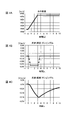
- FIG. 4 is a diagram showing the measurement results of the fluid according to the comparative example.
- 4A shows the relationship between time and the sound speed change of water
- FIG. 4B shows the relationship between the measurement result of time and water flow velocity
- FIG. 4C shows the output result when the measurement result of FIG. 4B is damped.
- the flow rate of water was measured in the order of survey line L1, survey line L2, survey line L3, survey line L1, survey line L2, survey line L3,.
- the propagation time Tf was first measured, then Tr was measured to determine the flow velocity V of the fluid 102 using the flow velocity Va of the fluid 102, and the flow velocity Vb was not used.
- the weighting of each survey line L1, L2, L3 was made equal to 1/3.
- the damping calculation was performed with a time constant of 5 seconds on the measurement result of FIG. 4B.
- the damping calculation is a first-order lag calculation, and the same effect as when passing through a first-order low-pass filter with a time constant of 5 seconds can be obtained.
- the fluid measuring device 1 is provided with a removal processing unit (not shown) that performs a damping process.
- the horizontal axis is time
- the vertical axis is the sound velocity C of water
- the horizontal axis is time
- the vertical axis is the measurement result of the flow velocity V of water
- the horizontal axis is time
- the vertical axis is damping processing in FIG. 4C.
- the measurement result of the flow velocity V of the collected water is shown.
- the sound speed C of water rises from 0 seconds to 3 seconds when the water temperature changes, and the sound speed C of water is constant after 3 seconds.
- FIG. 4C even if the measurement result of FIG. 4B is dumped, the error is not suppressed, and the error has an absolute value of 0.15 m / s at the maximum.
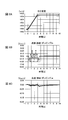
- FIG. 5 is a diagram showing the measurement results of the fluid according to the above embodiment.
- 5A shows the relationship between time and the sound speed change of water
- FIG. 5B shows the relationship between the measurement result of time and water flow velocity
- FIG. 5C shows the output result when the measurement result of FIG. 5B is damped.
- the flow rate of water was measured in the order of line L1, line L2, line L3, line L1, line L2, line L3,.
- the propagation times Tf and Tr were measured by changing the order, and the flow velocity Va and the flow velocity Vb of the fluid 102 were alternately measured in order in each of the measurement lines L1, L2, and L3.
- the weights of the ultrasonic probe pair 21, the ultrasonic probe pair 22, and the ultrasonic probe pair 23 were equal to 1/3.
- a damping calculation with a time constant of 5 seconds was performed on the measurement result of FIG. 5B.
- the values on the vertical and horizontal axes in FIGS. 5A to 5C are the same as those in FIGS. 4A to 4C.
- the error is suppressed from a maximum of 0.35 m / s to 0.12 m / s in absolute value as compared with FIG. 4B.
- FIG. 5C when the measurement result of FIG. 5B is damped, the error is greatly suppressed from the maximum of 0.15 m / s to 0.01 m / s as compared with FIG. 5C.
- the error can be canceled by measuring the flow velocity Va and the flow velocity Vb using a plurality of pairs of ultrasonic probes 10a1-10a3, 10b1-10b3, the measurement error can be suppressed.
- FIG. 6 is a diagram showing a fluid measurement result according to the above embodiment.
- 6A shows the relationship between time and the change in the sound speed of water
- FIG. 6B shows the relationship between the measurement result of time and the flow velocity of water
- FIG. 6C shows the output result when the measurement result of FIG. .
- the weight of the survey line L1 and the survey line L3 is set to 0.4
- the weight of the survey line L2 is set to 0.2
- the total of the three survey lines is set to 1.
- the flow rate of water was measured in the order of survey line L1, survey line L2, survey line L3, survey line L1, survey line L2, survey line L3,.
- each of the survey lines L1, L2, and L3 the propagation times Tf and Tr were measured while changing the order, and the flow velocity Va and the flow velocity Vb of the fluid 102 were alternately measured in order in each of the survey lines L1, L2, and L3.
- FIG. 6C a damping calculation with a time constant of 5 seconds was performed on the measurement result of FIG. 6B.
- the values on the vertical and horizontal axes in FIGS. 6A to 6C are the same as those in FIGS. 4A to 4C.
- the weighting of each of the measurement lines L1, L2, and L3 it is known that the flow velocity distribution changes when the flow velocity changes, but in advance, experimentally, empirically, or theoretically to cancel the influence. The determined value is used.
- the weighting of the survey lines L1 and L3 is set to 0.4 and the weight of the survey line L2 is set to 0.2, for example. In general, when the arrangement of the survey lines changes, the weighting also changes.
- the error increased from a maximum of 0.12 m / s to 0.21 m / s in absolute value as compared with FIG. 5B.
- FIG. 6C when the measurement result of FIG. 6B was subjected to a damping calculation, the error slightly increased from the maximum 0.01 m / s to 0.02 m / s in absolute value as compared with FIG. 5C.
- the error when each of the survey lines L1, L2, and L3 is weighted, the error is improved as compared with the comparative example of FIG. 4, but the error is slightly increased as compared with FIG. In this way, when the weights are not uniform, it is effective to assign the flow velocity Va and the flow velocity Vb to each of the measurement lines L1, L2, and L3 according to the weight.
- FIG. 7 is a diagram showing a fluid measurement result according to the above embodiment.
- 7A shows the relationship between time and the sound speed change of water
- FIG. 7B shows the relationship between the measurement result of time and water flow velocity
- FIG. 7C shows the output result when the measurement result of FIG. 7B is damped.
- the weight of the survey line L1 and the survey line L3 is set to 0.4
- the weight of the survey line L2 is set to 0.2
- the total of the three survey lines is set to 1.
- the flow rate of water was measured in the order of survey line L1, survey line L2, survey line L3, survey line L1, survey line L2, survey line L3,.
- the flow velocity of the fluid 102 to be measured on the measurement line L1 having the higher weight is set to Va
- the flow velocity of the fluid 102 to be measured on the measurement line L3 having the same weight is set to Vb opposite to the measurement line L1, and the measurement is performed on the measurement line L2 having the smallest weight.
- the flow rate Va and the flow rate Vb were alternately switched every time the flow rate of the fluid 102 was measured.
- the absolute value of the error was suppressed from a maximum of 0.21 m / s to 0.14 m / s as compared with FIG. 6B.
- FIG. 7C when the measurement result of FIG. 6B was subjected to a damping calculation, the error was suppressed from the maximum 0.02 m / s to 0.01 m / s in absolute value as compared with FIG. 6C.
- the measurement error is suppressed by assigning the flow velocities Va and Vb of the fluid 102 measured by the respective survey lines L1, L2, and L3 according to the weight. can do.
- the flow velocity measured by the pair of ultrasonic probes with the largest weighting is set to one of the flow velocity Va and the flow velocity Vb, and the weighting magnitude is the second and subsequent pairs.
- the setting order of setting two continuations in either the flow velocity Va or the flow velocity Vb may be repeated. That is, whether the flow rate measured by the pair with the highest weight is set to either Va or Vb, and the flow rate measured by the second and third pair with the highest weight is the flow velocity Va determined by the pair with the highest weight.
- V or Vb which is different from Vb, is set to Va or Vb, which is the same as the flow velocity Va or Vb determined by the pair with the largest weighting. If the flow velocity measured by the 7th and 7th weighted pair is set to Va or Vb which is different from the flow velocity Va or Vb determined by the most weighted pair, the error suppression effect is enhanced. Can do.
- the flow velocity Va and the flow velocity Vb may be alternately set in the order of weighting for the flow velocity measured by each pair of ultrasonic probes. That is, the flow velocity to be measured with the pair with the highest weight is set to either the flow velocity Va or Vb, and the flow velocity to be measured with the pair with the second highest weight is set to the flow velocity Va or Vb determined with the pair with the highest weight.
- the fluid measuring device 1 has the propagation times Tf and Tr of the fluid 102 even when an error occurs in the measurement result of the flow velocity V of the fluid 102 due to the change in the sound velocity C in the fluid 102.
- the ultrasonic propagation times Tf and Tr are measured a plurality of times to improve the S / N ratio, and the flow velocity V of the fluid 102 is accurately measured. be able to.
- the fluid measurement device of the present invention includes at least a pair of ultrasonic transmission / reception means for transmitting / receiving ultrasonic waves to a fluid flowing in a pipe, a time measurement unit for measuring a propagation time of ultrasonic waves transmitted / received by the ultrasonic transmission / reception means, A flow velocity measurement unit that obtains the flow velocity of the fluid from the ultrasonic propagation time measured by the time measurement unit, wherein one of the pair of ultrasonic transmission / reception means is arranged upstream of the pipe and the other is arranged downstream of the pipe.
- the flow velocity Va and the flow velocity Vb are measured by changing the measurement order of the propagation time.
- the sign of the error that occurs and the error that occurs in the flow velocity Vb can be reversed. Therefore, since the error can be canceled by using the flow velocity Va and the flow velocity Vb, the ultrasonic wave propagation time can be measured a plurality of times to improve the S / N ratio, and the fluid flow velocity can be accurately measured.
- the time measurement unit alternately measures the first propagation time and the second propagation time, and the first propagation time and the second propagation time in which the flow velocity measurement unit continues.
- the flow velocity Va may be obtained from the second propagation time and the subsequent first propagation time.
- the time measuring unit performs a plurality of times of measurement of a propagation time during which the ultrasonic wave propagates from the upstream ultrasonic transmitting / receiving unit to the downstream ultrasonic transmitting / receiving unit.
- the second propagation time may be obtained by measuring the propagation time during which the ultrasonic wave propagates from the downstream ultrasonic wave transmitting / receiving unit to the upstream ultrasonic wave transmitting / receiving unit a plurality of times.
- the flow velocity measuring unit has a plurality of pairs of ultrasonic transmission / reception means, measures the first propagation time and the second propagation time in each pair, and sequentially turns each pair.
- the flow velocity Va and the flow velocity Vb may be measured alternately. With this configuration, the error can be canceled by measuring the flow velocity Va and the flow velocity Vb with a plurality of pairs of ultrasonic transmission / reception means.
- each pair of the plurality of pairs of ultrasonic transmission / reception means is weighted, and the flow velocity measured by each pair is set to one of the flow velocity Va and the flow velocity Vb according to the weighting magnitude.
- the flow velocity of the fluid may be obtained by setting and weighted addition. With this configuration, the measurement accuracy can be improved by weighting each pair of ultrasonic transmission / reception means and measuring the flow velocity of the fluid.
- the flow velocity measured by the pair of ultrasonic transmission / reception means having the largest weight is set to one of the flow velocity Va and the flow velocity Vb, and the weight of the second and subsequent pairs is set.
- the setting sequence of setting the flow velocity Va or the flow velocity Vb to two continuations may be repeated.
- the error suppression effect can be enhanced by setting the fluid flow velocity measured by each pair of ultrasonic transmission / reception means in the order of weighting in a predetermined setting order.
- the flow velocity Va and the flow velocity Vb may be alternately set in the order of weighting for the flow velocity measured by each pair of the ultrasonic transmission / reception means.
- the error suppression effect can be enhanced by setting the fluid flow velocity measured by each pair of ultrasonic transmission / reception means in the order of weighting in a predetermined setting order.
- the flow velocity Va and the flow velocity Vb may be alternately set as the flow velocity measured by the pair of ultrasonic transmission / reception means having the smallest weight. With this configuration, the error suppression effect can be enhanced.
- the fluid measuring device of the present invention it is preferable to have a removal processing unit that removes a high-frequency component from the fluid flow velocity obtained by the flow velocity measuring unit. With this configuration, it is possible to stabilize the measurement result and reduce an error in the measurement result of the fluid flow velocity.
- the fluid measuring device of the present invention it is preferable to remove high frequency components by a damping process. With this configuration, the measurement result can be stabilized by simple processing, and the error in the measurement result of the fluid flow velocity can be reduced.
Landscapes
- Physics & Mathematics (AREA)
- Electromagnetism (AREA)
- Fluid Mechanics (AREA)
- General Physics & Mathematics (AREA)
- Measuring Volume Flow (AREA)
Abstract
流体における音速が変化する場合であっても、精度良く流体の流速を計測することができること。流体計測装置(1)は、流体(102)へ超音波を送受信する少なくとも一対の超音波送受信手段と、超音波の伝搬時間を計測する時間計測部(34)と、超音波の伝搬時間から流体の流速を求める流速計測部(36)と、を備え、時間計測部が、上流側の超音波送受信手段(10a)から下流側の超音波送受信手段(10b)に超音波が伝搬する第1の伝搬時間(Tf)と、下流側の超音波送受信手段から上流側の超音波送受信手段に超音波が伝搬する第2の伝搬時間(Tr)を計測する。流速計測部が、第1の伝搬時間の次に第2の伝搬時間を計測して求めた流速Vaと、第2の伝搬時間の次に第1の伝搬時間を計測して求めた流速Vbとを使って誤差をキャンセルして流体の流速Vを求める。
Description
本発明は、超音波を利用して流体の流速や流量を計測する流体計測装置に関する。
一般的に超音波を利用して流体の流速や流量を計測する方法として、伝搬時間差法が知られている(例えば、特許文献1参照)。この方法は、流体の流れに対し、流れに沿う方向と流れに逆らう方向で超音波を送受信し、この2方向の超音波の伝搬時間の違いが流体の流速により変化する現象を利用している。特許文献1には、超音波の送受信を複数回実施して、測定された波形を同期加算平均することで、S/N比(信号と雑音の比:Signal to Noise Ratio)を向上させる技術が開示されている。
伝搬時間差法において、超音波の音速は一定ではなく、温度等の他の物理量の影響を受けて変化する。このため、伝搬時間差法によって流体に対する超音波の伝搬時間を複数回測定してS/N比を向上させようとすると、計測時間が長くなる分だけ温度変化の影響を長く受けて、計測誤差が大きくなる問題がある。
本発明は、このような問題に鑑みてなされたもので、その目的とするところは、流体における音速が変化する場合であっても、精度良く流体の流速を計測することができる流体計測装置を提供することにある。
本発明の流体計測装置は、配管内を流れる流体へ超音波を送受信する少なくとも一対の超音波送受信手段と、前記超音波送受信手段により送受信された超音波の伝搬時間を計測する時間計測部と、前記時間計測部で計測された超音波の伝搬時間から流体の流速を求める流速計測部と、を備え、前記一対の超音波送受信手段の一方が前記配管の上流、他方が前記配管の下流に配設され、前記時間計測部が、前記上流側の超音波送受信手段から前記下流側の超音波送受信手段に超音波が伝搬する第1の伝搬時間及び前記下流側の超音波送受信手段から前記上流側の超音波送受信手段に超音波が伝搬する第2の伝搬時間を計測し、前記流速計測部が、第1の伝搬時間の次に第2の伝搬時間を計測して求めた流速Vaと、第2の伝搬時間の次に第1の伝搬時間を計測して求めた流速Vbとを使って誤差をキャンセルするように流体の流速を求めることを特徴とする。
この構成により、流体における音速が変化することにより流体の流速の計測結果に誤差が生じる場合であっても、伝搬時間の計測順序を替えて流速Vaと流速Vbを計測することで、流速Vaに生じる誤差と流速Vbに生じる誤差の正負を逆にすることができる。よって、流速Vaと流速Vbを用いることで誤差をキャンセルできるため、超音波の伝搬時間を複数回測定してS/N比を向上させて、流体の流速を精度良く計測することができる。
本発明によれば、流体における音速が変化する場合であっても、精度良く流体の流速を計測することができる。
以下、本発明の一実施の形態に係る流体計測装置について、詳細に説明する。図1は、一実施の形態の流体計測装置の概略構成図である。
流体計測装置1は、配管100内に流れる流体102の流速を超音波を用いて計測する。配管100には、一対の超音波送受信手段として一対の超音波プローブ10a、10bが、流体102の流れに対して斜め方向で対向するように配置されている。超音波プローブ10aは、配管100内の流体102の流れに対して上流側に配設され、超音波プローブ10bは下流側に配設されている。超音波プローブ10a、10bは、それぞれ配管100に取り付けられた楔12a、12bと、楔12a、12bに超音波を印加する超音波振動子11a、11bとを備えている。
超音波振動子11aは、スイッチ部33aを介して、送信部31及び受信部32に接続され、超音波振動子11bは、スイッチ部33bを介して送信部31及び受信部32に接続されている。スイッチ部33a、33bは、超音波プローブ10a、10bの接続先を送信部31又は受信部32に切り替えて、一対の超音波プローブ10a、10bを送信用又は受信用に切り替えている。
送信部31は時間計測部34に接続されており、時間計測部34の指示に応じて超音波振動子11a、11bに駆動信号を出力する。受信部32は、時間計測部34に接続されており、超音波振動子11a、11bに入力された電気信号を時間計測部34に出力する。
時間計測部34は、送信部31から駆動信号が出力されてから、受信部32から電気信号が入力されるまでの伝搬時間を計測する。スイッチ部33a、33bはそれぞれ制御部35に接続されており、制御部35からの信号によってスイッチ33a、33bは切り替えられ、超音波プローブ10a、10bの送受信関係が反対にされる。
流体計測装置1では、時間計測部34の指示により、送信部31からスイッチ部33aを介して超音波の波形に応じた駆動信号(電流)を超音波振動子11aに印加して、超音波を発生させる。超音波は楔12a及び壁面101を透過し、配管100内の流体102に所定の角度ψで入射する。配管100内に入射した超音波は、流体102の流れに沿って超音波プローブ10aに対向する超音波プローブ10bに伝搬される。超音波プローブ10bに伝搬された超音波は、超音波振動子11bで電気信号に変換され、スイッチ33bを介して受信部32に入力される。これにより、時間計測部34では、上流の超音波プローブ10aから下流の超音波プローブ10bに向かう超音波の伝搬時間Tfが計測される。
また超音波プローブ10a、10bを逆に切り替えると、送信部31からスイッチ部33bを介して超音波振動子11bに駆動信号を印加して超音波を発生させる。超音波は楔12b及び壁面101を透過し、配管100内の流体102に所定の角度ψで入射して、超音波プローブ10aに伝搬される。超音波振動子11aに入力された超音波は電気信号に変換され、スイッチ33aを介して受信部32に入力される。これにより、時間計測部34では、下流側の超音波プローブ10bから上流側の超音波プローブ10aに向かう超音波の伝搬時間Trが計測される。
時間計測部34には、制御部35を介して流速計測部36が接続され、流速計測部36には流量計測部37が接続されている。流速計測部36は超音波の伝搬時間Tf、Trから流体102の流速を算出し、流量計測部37は流速計測部36で求められた流体102の流速から流体102の流量を算出する。流速計測部36で求められた流体102の流速は、除去処理部(不図示)において、例えば後述するダンピング処理等を行って高周波成分が除去されてもよい。これにより、計測結果を安定化させ、流体102の流速の計測結果における誤差を小さくすることができる。
なお、時間計測部34、制御部35、流速計測部36、流量計測部37は、各種処理を実行するプロセッサやメモリ等により構成される。メモリは、用途に応じてROM(Read Only Memory)、RAM(Random Access Memory)等の一つ又は複数の記憶媒体で構成される。時間計測部34は、時間計測回路、時間計測器、時間計測装置等で構成されていてもよい。制御部35は、制御回路、制御器、制御装置等で構成されていてもよい。流速計測部36は、流速計測回路、流速計測器、流速計測装置等で構成されていてもよい。流量計測部37は、流量計測回路、流量計測器、流量計測装置等で構成されていてもよい。
次に一般的な流体102の流速Vと流量Qの算出方法について説明する。伝搬時間Tr、Tfは、流体102の流速V、流体102の音速C、超音波プローブ10aから超音波プローブ10bまでの超音波の伝搬路長L、流体102の流れ方向に対する超音波の伝搬方向の角度ψを用いて、次のように表わされることが知られている。
Tf=L/(C+Vcosψ) (1)
Tr=L/(C-Vcosψ) (2)
Tf=L/(C+Vcosψ) (1)
Tr=L/(C-Vcosψ) (2)
式(1)、(2)より、流体102の流速Vについて解くと式(3)が示される。
V=L/2cosψ×((1/Tf)-(1/Tr)) (3)
V=L/2cosψ×((1/Tf)-(1/Tr)) (3)
流体の流量Qは、流体102の流速V、配管100の断面積Aを用いて式(4)のように表わされる。
Q=V×A (4)
配管100の断面積Aは、配管100の内径Dを用いて式(5)のように表わされる。
A=(D/2)2×π (5)
ここで、伝搬時間TfあるいはTrの計測を複数回連続して実施し、測定された波形を同期加算平均することでS/N比を向上させて、測定精度を改善することが可能である。
Q=V×A (4)
配管100の断面積Aは、配管100の内径Dを用いて式(5)のように表わされる。
A=(D/2)2×π (5)
ここで、伝搬時間TfあるいはTrの計測を複数回連続して実施し、測定された波形を同期加算平均することでS/N比を向上させて、測定精度を改善することが可能である。
しかしながら、式(1)から(3)で示される流体102の流速Vは、流体102の音速Cが一定であることを前提としている。実際には、流体102の音速Cは、例えば流体102の温度により変化することが知られている。ここで、伝搬時間Tfを計測したときの流体102の音速Cに対して、音速の変化を考慮した伝搬時間Tr´を計測したときの流体102の音速がC+ΔCに変化した場合、伝搬時間Tr´は式(6)のように表わされる。
Tr´=L/(C+ΔC-Vcosψ) (6)
式(3)、式(6)より、流体102の流速V´を求めると、式(7)のように示される。
V´=L/2cosψ×((1/Tf)-(1/Tr´))
=(C+Vcosψ-(C+ΔC-Vcosψ))/2cosψ
=V-(ΔC/2cosψ) (7)
式(7)に示すように、流体102の流速V´に-(ΔC/2cosψ)だけ誤差が発生する。
Tr´=L/(C+ΔC-Vcosψ) (6)
式(3)、式(6)より、流体102の流速V´を求めると、式(7)のように示される。
V´=L/2cosψ×((1/Tf)-(1/Tr´))
=(C+Vcosψ-(C+ΔC-Vcosψ))/2cosψ
=V-(ΔC/2cosψ) (7)
式(7)に示すように、流体102の流速V´に-(ΔC/2cosψ)だけ誤差が発生する。
超音波の送受信を複数回実施してS/N比を向上させようとすると、伝搬時間Tf、Trを計測する時間が長くなり、音速Cの変化による影響を長く受けて、流体102の音速Cの変化ΔCが大きくなる傾向がある。このため、流体102の流速V´の誤差は増大する。そこで、本実施の形態においては、超音波の伝搬時間Tf、Trを複数回測定することで、流体102の流速V´の誤差が大きくなる場合であっても、伝搬時間Tr、Tfの計測順序を替えて流体の流速を計測することで、誤差をキャンセルするようにしている。
以下、流速計測部36による流体102の流速Vの計測方法について詳細に説明する。本実施の形態においては、流速計測部36は、伝搬時間Tfの次に伝搬時間Trを計測して求めた流体102の流速Vaと、伝搬時間Trの次に伝搬時間Tfを計測して求めた流体102の流速Vbとを使って、計測誤差をキャンセルする。
具体的には、時間計測部34により、最初に伝搬時間Tf1が計測される。次に制御部35によりスイッチ部33a、33bが切り替えられて、続いて時間計測部34により伝搬時間Tr1が計測される。続いて時間計測部34により、伝搬時間Tr2が測定される。再び制御部35によりスイッチ部33a、33bが切り替えられて、時間計測部34により伝搬時間Tf2が計測される。伝搬時間Tf1、Tr1、Tr2、Tf2は流速計測部36に入力され、時間計測部34で流体102の流速Vが算出される。
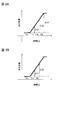
ここで、図2Aに示すように流体102の音速がCからそれぞれC+ΔC1、C+ΔC2、C+ΔC3に変化したとすると、伝搬時間Tf1、Tr1、Tr2、Tf2は式(8)から(11)のように示される。なお、図2Aの横軸は時間、縦軸に水の音速を示しており、所定の期間に亘って水温が変化した場合の音速Cの変化を示している。
Tf1=L/(C+Vcosψ) (8)
Tr1=L/(C+ΔC1-Vcosψ) (9)
Tr2=L/(C+ΔC2-Vcosψ) (10)
Tf2=L/(C+ΔC3+Vcosψ) (11)
Tf1=L/(C+Vcosψ) (8)
Tr1=L/(C+ΔC1-Vcosψ) (9)
Tr2=L/(C+ΔC2-Vcosψ) (10)
Tf2=L/(C+ΔC3+Vcosψ) (11)
ここで、流体102(水)において時間計測部34で計測される伝搬時間Tf1、Tr1、Tr2、Tf2の計測間隔を一定とすると、各計測間隔は短いため各計測間隔における流体102の音速の変化量は一定となり、ΔC1=ΔCとすると、ΔC2=2ΔC、ΔC3=3ΔCと表すことができる。
これらを式(8)から(11)に代入すると、伝搬時間Tf1、Tr1、Tr2、Tf2は式(12)から(15)のように示される。
Tf1=L/(C+Vcosψ) (12)
Tr1=L/(C+ΔC-Vcosψ) (13)
Tr2=L/(C+2ΔC-Vcosψ) (14)
Tf2=L/(C+3ΔC+Vcosψ) (15)
Tf1=L/(C+Vcosψ) (12)
Tr1=L/(C+ΔC-Vcosψ) (13)
Tr2=L/(C+2ΔC-Vcosψ) (14)
Tf2=L/(C+3ΔC+Vcosψ) (15)
伝搬時間Tf1とTr1とから求めた流体102の流速をVa、伝搬時間Tr2とTf1とから求めた流体102の流速をVbとし、式(12)から(15)より流体102の流速Va、Vbについて解くと式(16)、(17)が示される。
Va=L/2cosψ×((1/Tf1)-(1/Tr1))
=((C+Vcosψ)-(C+ΔC-Vcosψ)/2cosψ
=V-(ΔC/2cosψ) (16)
Vb=L/2cosψ×((1/Tf2)-(1/Tr1))
=((C+3ΔC+Vcosψ)-(C+2ΔC-Vcosψ)/2cosψ
=V+(ΔC/2cosψ) (17)
Va=L/2cosψ×((1/Tf1)-(1/Tr1))
=((C+Vcosψ)-(C+ΔC-Vcosψ)/2cosψ
=V-(ΔC/2cosψ) (16)
Vb=L/2cosψ×((1/Tf2)-(1/Tr1))
=((C+3ΔC+Vcosψ)-(C+2ΔC-Vcosψ)/2cosψ
=V+(ΔC/2cosψ) (17)
式(16)、(17)を用いて流体102の流速Vaと流速Vbを平均して流体の流速V´を求めると、式(18)のように示される。
V´=(Va+Vb)/2
=((V-(ΔC/2cosψ))+(V+(ΔC/2cosψ))/2
=V (18)
V´=(Va+Vb)/2
=((V-(ΔC/2cosψ))+(V+(ΔC/2cosψ))/2
=V (18)
このように、流体102の流速Vaを求めると誤差+(ΔC/2cosψ)が発生し、流体102の流速Vbを求めると誤差-(ΔC/2cosψ)が発生するため、VaとVbの平均をとることにより誤差をキャンセルすることができる。本実施の形態の流体計測装置1は、時間計測部34で伝搬時間Tf、Trの計測順序を替えて伝搬時間を計測し、流速計測部36で流体102の流速Va及び流速Vbを求めて誤差をキャンセルすることで、流体の流速Vを精度良く求めることができる。流量計測部37は、流速計測部36で算出された流体102の流速Vを用いて、上記式(4)より流体102の流量Qを算出する。
また、制御部35でスイッチ部33a、33bを切り替えることにより、時間計測部34で伝搬時間をTf1、Tr1、Tf2、Tr2、・・・のように交互に計測し、流速計測部36で伝搬時間Tf1とTr1とから流体102の流速Vaを求め、伝搬時間Tr1とTf2とから流体102の流速Vbを求めてもよい。図2Bに示すように、伝搬時間Tr1、Tf2、・・・に対応する流体102の音速の変化がΔC、2ΔCだとすると、伝搬時間Tf1、Tr1、Tf2は式(19)から(21)のように示される。
Tf1=L/(C+Vcosψ) (19)
Tr1=L/(C+ΔC-Vcosψ) (20)
Tf2=L/(C+2ΔC+Vcosψ) (21)
Tf1=L/(C+Vcosψ) (19)
Tr1=L/(C+ΔC-Vcosψ) (20)
Tf2=L/(C+2ΔC+Vcosψ) (21)
伝搬時間Tf1とTr1とから求めた流体102の流速をVa、伝搬時間Tr1とTf2とから求めた流体102の流速をVbとすると、式(22)、(23)が示される。
Va=L/2cosψ×((1/Tf1)-(1/Tr1))
=((C+Vcosψ)-(C+ΔC-Vcosψ)/2cosψ
=V-(ΔC/2cosψ) (22)
Vb=L/2cosψ×((1/Tf2)-(1/Tr1))
=((C+2ΔC+Vcosψ)-(C+ΔC-Vcosψ)/2cosψ
=V+(ΔC/2cosψ) (23)
Va=L/2cosψ×((1/Tf1)-(1/Tr1))
=((C+Vcosψ)-(C+ΔC-Vcosψ)/2cosψ
=V-(ΔC/2cosψ) (22)
Vb=L/2cosψ×((1/Tf2)-(1/Tr1))
=((C+2ΔC+Vcosψ)-(C+ΔC-Vcosψ)/2cosψ
=V+(ΔC/2cosψ) (23)
式(22)、(23)を用いて流体102の流速Vaと流速Vbを平均して流体の流速V´を求めると、式(24)のように示される。上記した伝搬時間Tf1、Tr1、Tr2、Tf2から流体102の流速Vを求めるよりも、流速Vaと流速Vbの算出に共通のTr1を用いることで伝搬時間の計測回数を少なくして、誤差をキャンセルすることができる。
V´=(Va+Vb)/2
=((V-(ΔC/2cosψ))+(V+(ΔC/2cosψ))/2
=V (24)
V´=(Va+Vb)/2
=((V-(ΔC/2cosψ))+(V+(ΔC/2cosψ))/2
=V (24)
さらに、伝搬時間Tf2とTr2とから流体102の流速Vaを求め、伝搬時間Tr2とTf3(3回目の上流側から下流側の超音波プローブに超音波が伝搬する伝搬時間)とから流体102の流速Vbを求めることにより、流体102の流速Vを精度良く計測し続けていくことができる。
また、伝搬時間Tfの計測を複数回連続して実施すると共に、伝搬時間Trの計測を複数回連続して実施することで、S/N比を向上させ、測定精度を改善することができる。
次に図3を参照して、複数対の超音波プローブを用いた測定方法について説明する。図3は、上記実施の形態に係る複数対の超音波送受信手段を示す図である。図3Aは配管の断面図であり、図3Bは配管の側面図である。図3に示すように、流体計測装置1は、3対の超音波プローブ10a1-10a3、10b1-10b3によって、3つの測線L1、L2、L3で超音波の伝搬時間Tr、Tfを計測している。超音波プローブ10a1、10a2、10a3は配管100内の上流側に配設され、超音波プローブ10b1、10b2、10b3は配管の下流側に配設されている。
以下、3対の超音波プローブ10a1-10a3、10b1-10b3を有している流体計測装置1を用いて、流体102の音速が変化した場合に発生する流体102の流速の誤差をシミュレーションした結果を図4から図7に示す。流体102として水を用い、1秒間に1℃の割合で3秒間に亘って水温が変化した場合の音速Cの変化を模擬した。流体102の流速V=0、配管100の内径は50mmの場合をシミュレーションした。
図4は、比較例に係る流体の計測結果を示す図である。図4Aは時間と水の音速変化の関係を示し、図4Bは時間と水の流速の計測結果の関係を示し、図4Cは図4Bの計測結果をダンピング演算した場合の出力結果を示している。図4Bにおいて、水の流速の計測は、測線L1、測線L2、測線L3、測線L1、測線L2、測線L3、・・・の順番で行った。各線において最初に伝搬時間Tfを計測し、次にTrを計測して流体102の流速Vaを使って流体102の流速Vを求め、流速Vbは使わなかった。各測線L1、L2、L3の重み付けは1/3で均等とした。
図4Cにおいて、ダンピング演算は、図4Bの測定結果に対して時定数5秒の演算をした。ここで、ダンピング演算は一次遅れ演算であり、時定数5秒の一次ローパスフィルタを通過した場合と同じ効果を得ることができる。流体102の流速Vの計測結果における高周波成分を除去して、簡易な処理で計測結果を安定化させる効果がある。この場合、流体計測装置1は、ダンピング処理を行う除去処理部(不図示)を設けるようにする。なお、図4Aにおいて横軸は時間、縦軸は水の音速C、図4Bにおいて横軸は時間、縦軸は水の流速Vの計測結果、図4Cにおいて横軸は時間、縦軸はダンピング処理した水の流速Vの計測結果を示している。
図4Aに示すように、水温が変化した0秒から3秒の間に水の音速Cが上昇しており、3秒以降は水の音速Cが一定になっている。図4Bに示すように、水温が変化した0秒から3秒の間に、真値の水の流速V=0を外れた誤差が、絶対値で最大0.35m/s生じている。図4Cに示すように、図4Bの計測結果をダンピング演算しても誤差が抑制されず、誤差が絶対値で最大0.15m/s生じている。
図5は、上記実施の形態に係る流体の計測結果を示す図である。図5Aは時間と水の音速変化の関係を示し、図5Bは時間と水の流速の計測結果の関係を示し、図5Cは図5Bの計測結果をダンピング演算した場合の出力結果を示している。図5Bにおいて、水の流速の計測は、測線L1、測線L2、測線L3、測線L1、測線L2、測線L3、・・・の順番で行った。各測線L1、L2、L3において、伝搬時間Tf、Trの順序を替えて計測して、各測線L1、L2、L3で順番に流体102の流速Vaと流速Vbとを交互に計測した。各超音波プローブの対21、超音波プローブの対22、超音波プローブの対23の重み付けは1/3で均等とした。図5Cにおいては、図5Bの測定結果に対して時定数5秒のダンピング演算をした。図5Aから図5Cの縦軸及び横軸の値は、図4Aから図4Cと同様である。
図5Bに示すように、誤差が、図4Bと比較すると、絶対値で最大0.35m/sから0.12m/sに抑制されている。図5Cに示すように、図5Bの計測結果をダンピング演算した場合、誤差が、図5Cと比較すると、絶対値で最大0.15m/sから0.01m/sに大幅に抑制されている。このように、複数対の超音波プローブ10a1-10a3、10b1-10b3を用いて流速Va及び流速Vbを計測することにより誤差をキャンセルできるため、計測誤差を抑制することができる。
次に、図6を参照して測線の重み付けが均等でない場合の測定方法について説明する。図6は、上記実施の形態に係る流体の計測結果を示す図である。図6Aは時間と水の音速変化の関係を示し、図6Bは時間と水の流速の計測結果の関係を示し、図6Cは図6Bの計測結果をダンピング演算した場合の出力結果を示している。測線L1と測線L3の重み付けを0.4とし、測線L2の重み付けを0.2とし、3測線を合計すると1になるようにしている。図6Bにおいて、水の流速の計測は、測線L1、測線L2、測線L3、測線L1、測線L2、測線L3、・・・の順番で行った。各測線L1、L2、L3において、伝搬時間Tf、Trを順序を替えて計測して、各測線L1、L2、L3で順番に流体102の流速Vaと流速Vbとを交互に計測した。図6Cにおいては、図6Bの測定結果に対して時定数5秒のダンピング演算をした。図6Aから図6Cの縦軸及び横軸の値は、図4Aから図4Cと同様である。なお、各測線L1、L2、L3の重み付けにおいては、流速が変化した際に流速分布が変化することが知られているが、その影響をキャンセルするように予め実験的、経験的又は理論的に求められた値が用いられる。測線L1と測線L3の重み付けを0.4とし、測線L2の重み付けを0.2とするのは、その一例であり、一般に測線の配置が変化すると重み付けも変化する。
図6Bに示すように、誤差が、図5Bと比較すると絶対値で最大0.12m/sから0.21m/sに増加した。図6Cに示すように、図6Bの計測結果をダンピング演算した場合、誤差が、図5Cと比較すると絶対値で最大0.01m/sから0.02m/sに僅かに増加した。このように、各測線L1、L2、L3が重み付けされる場合、図4の比較例と比べると、誤差は改善されるものの、図5と比較すると、僅かに誤差が大きくなっている。このように重み付けが均等でない場合には、重みに応じて各測線L1、L2、L3に流速Va及び流速Vbを割り付けることが有効である。
次に、図7を参照して測線L1、L2、L3の重み付けに応じて各測線に流速Va及び流速Vbを割り付けた場合について説明する。図7は、上記実施の形態に係る流体の計測結果を示す図である。図7Aは時間と水の音速変化の関係を示し、図7Bは時間と水の流速の計測結果の関係を示し、図7Cは図7Bの計測結果をダンピング演算した場合の出力結果を示している。測線L1と測線L3の重み付けを0.4とし、測線L2の重み付けを0.2とし、3測線を合計すると1になるようにしている。図7Bにおいて、水の流速の計測は、測線L1、測線L2、測線L3、測線L1、測線L2、測線L3、・・・の順番で行った。重み付けが大きい測線L1で計測する流体102の流速をVaに定め、同じく重み付けが大きい測線L3で計測する流体102の流速を測線L1と逆のVbに定め、一番重み付けの小さい測線L2で計測する流体102の流速を計測の度に流速Vaと流速Vbとを交互に切り替えた。すなわち、測線L1(Va)、測線L2(Va)、測線L3(Vb)、測線L1(Va)、測線L2(Vb)、測線L3(Vb)、測線L1(Va)、測線L2(Va)、・・・の順番で計測した。図7Cにおいては、図7Bの測定結果に対して時定数5秒のダンピング演算をした。図7Aから図7Cの縦軸及び横軸の値は、図4Aから図4Cと同様である。
図7Bに示すように、誤差が、図6Bと比較すると絶対値で最大0.21m/sから0.14m/sに抑制された。図7Cに示すように、図6Bの計測結果をダンピング演算した場合、誤差が、図6Cと比較すると絶対値で最大0.02m/sから0.01m/sに抑制された。このように、各測線L1、L2、L3が重み付けされる場合は、各測線L1、L2、L3で計測される流体102の流速Va及びVbを、重み付けに応じて割り付けることで、計測誤差を抑制することができる。
なお、重み付けに応じて測線を割り付ける場合には、最も重み付けが大きい超音波プローブの対で計測する流速を流速Va及び流速Vbのいずれか一方に設定し、重み付けの大きさが2番目以降の対に対しては、計測する流速を流速Va及び流速Vbのいずれか他方に2連続で設定した後、流速Va及び流速Vbのいずれか一方に2連続で設定する設定順序を繰り返してもよい。すなわち、一番重み付けの大きい対で計測する流速をVaかVbのどちらかに定めて、二番目と三番目の重み付けの大きい対で計測する流速を一番重み付けが大きい対で定めた流速VaかVbと違う方のVaかVbに定めて、四番目と五番目に重み付けの大きい対で計測する流速を一番重み付けが大きい対で定めた流速VaかVbと同じVaかVbに定めて、六番目と七番目に重み付けの大きい対で計測する流速を一番重み付けが大きい対で定めた流速VaかVbと違う方のVaかVbに定めて、という順に定めると、誤差の抑制効果を高めることができる。
また、超音波プローブの各対で計測する流速を、重み付けの順番で流速Vaと流速Vbとを交互に設定してもよい。すなわち、一番重み付けの大きい対で計測する流速を流速VaかVbのどちらかに定めて、二番目に重み付けの大きい対で計測する流速を一番重み付けが大きい対で定めた流速VaかVbと違う方のVaかVbに定めて、三番目に重み付けの大きい対で計測する流速を一番重み付けが大きい対で定めた流速VaかVbと同じVaかVbに定めて、四番目に重み付けの大きい対で計測する流速を一番重み付けが大きい対で定めた流速VaかVbと違う方のVaかVbに定めて、という順に定めても高い誤差の抑制効果を得ることができる。また、最も重み付けが小さい超音波プローブの対で計測する流速に流速Va及び流速Vbとを交互に設定してもよい。これにより、より高い誤差の抑制効果が得られる。
以上のように、本実施の形態の流体計測装置1は、流体102における音速Cが変化することにより流体102の流速Vの計測結果に誤差が生じる場合であっても、伝搬時間Tf、Trの計測順序を替えて流速Vaと流速Vbを計測することで、流速Vaに生じる誤差と流速Vbに生じる誤差の正負を逆にすることができる。よって、流速Vaと流速Vbを用いることで誤差をキャンセルできるため、超音波の伝搬時間Tf、Trを複数回測定してS/N比を向上させて、流体102の流速Vを精度良く計測することができる。
なお、本発明は上記実施の形態に限定されず、種々変更して実施することが可能である。上記実施の形態において、添付図面に図示されている大きさや形状などについては、これに限定されず、本発明の効果を発揮する範囲内で適宜変更することが可能である。その他、本発明の目的の範囲を逸脱しない限りにおいて適宜変更して実施することが可能である。
下記に上記実施の形態における特徴点を整理する。
本発明の流体計測装置は、配管内を流れる流体へ超音波を送受信する少なくとも一対の超音波送受信手段と、前記超音波送受信手段により送受信された超音波の伝搬時間を計測する時間計測部と、前記時間計測部で計測された超音波の伝搬時間から流体の流速を求める流速計測部と、を備え、前記一対の超音波送受信手段の一方が前記配管の上流、他方が前記配管の下流に配設され、前記時間計測部が、前記上流側の超音波送受信手段から前記下流側の超音波送受信手段に超音波が伝搬する第1の伝搬時間及び前記下流側の超音波送受信手段から前記上流側の超音波送受信手段に超音波が伝搬する第2の伝搬時間を計測し、前記流速計測部が、第1の伝搬時間の次に第2の伝搬時間を計測して求めた流速Vaと、第2の伝搬時間の次に第1の伝搬時間を計測して求めた流速Vbとを使って誤差をキャンセルするように流体の流速を求めることを特徴とする。
この構成により、流体における音速が変化することにより流体の流速の計測結果に誤差が生じる場合であっても、伝搬時間の計測順序を替えて流速Vaと流速Vbを計測することで、流速Vaに生じる誤差と流速Vbに生じる誤差の正負を逆にすることができる。よって、流速Vaと流速Vbを用いることで誤差をキャンセルできるため、超音波の伝搬時間を複数回測定してS/N比を向上させて、流体の流速を精度良く計測することができる。
本発明の流体計測装置においては、前記時間計測部が第1の伝搬時間と第2の伝搬時間とを交互に計測し、前記流速計測部が連続する第1の伝搬時間と第2の伝搬時間から前記流速Vaを求め、該第2の伝搬時間と後続する第1の伝搬時間から前記流速Vbを求めてもよい。この構成により、超音波の伝搬時間の計測回数を少なくすることができる。
本発明の流体計測装置においては、前記時間計測部が、前記上流側の超音波送受信手段から前記下流側の超音波送受信手段に超音波が伝搬する伝搬時間の計測を複数回実施して第1の伝搬時間を求め、前記下流側の超音波送受信手段から前記上流側の超音波送受信手段に超音波が伝搬する伝搬時間の計測を複数回実施して第2の伝搬時間を求めてもよい。この構成により、S/N比を向上させ、さらに計測精度を向上させることができる。
本発明の流体計測装置においては、前記流速計測部が、複数対の超音波送受信手段を有し、各対において第1の伝搬時間及び第2の伝搬時間を計測して、各対で順番に前記流速Vaと前記流速Vbとを交互に計測してもよい。この構成により、複数対の超音波送受信手段で流速Vaと流速Vbを計測することで、誤差をキャンセルすることができる。
本発明の流体計測装置においては、前記複数対の超音波送受信手段の各対を重み付けし、重み付けの大きさに応じて各対で計測する流速を前記流速Va及び前記流速Vbのいずれか一方に設定して重み付け加算により流体の流速を求めてもよい。この構成により、各対の超音波送受信手段を重み付けして流体の流速を計測することで、計測精度を向上させることができる。
本発明の流体計測装置においては、最も重み付けが大きい前記超音波送受信手段の対で計測する流速を前記流速Va及び前記流速Vbのいずれか一方に設定し、重み付けの大きさが2番目以降の対に対しては、計測する流速を前記流速Va及び前記流速Vbのいずれか他方に2連続で設定した後に前記流速Va及び前記流速Vbのいずれか一方に2連続で設定する設定順序を繰り返してもよい。この構成により、各対の超音波送受信手段で計測される流体の流速を重み付けの順番に、所定の設定順序で設定することで、誤差の抑制効果を高めることができる。
本発明の流体計測装置においては、前記超音波送受信手段の各対で計測する流速を、重み付けの順番で前記流速Vaと前記流速Vbとを交互に設定してもよい。この構成により、各対の超音波送受信手段で計測される流体の流速を重み付けの順番に、所定の設定順序で設定することで、誤差の抑制効果を高めることができる。
本発明の流体計測装置においては、最も重み付けが小さい前記超音波送受信手段の対で計測する流速に流速Va及び流速Vbとを交互に設定してもよい。この構成により、誤差の抑制効果を高めることができる。
本発明の流体計測装置においては、前記流速計測部で求められた流体の流速から高周波成分を除去する除去処理部を有することが好ましい。この構成により、計測結果を安定化させ、流体の流速の計測結果における誤差を小さくすることができる。
本発明の流体計測装置においては、ダンピング処理により高周波成分を除去することが好ましい。この構成により、簡易な処理で計測結果を安定化させ、流体の流速の計測結果における誤差を小さくすることができる。
本出願は、2016年5月26日出願の特願2016-105029に基づく。この内容は、全てここに含めておく。
Claims (10)
- 配管内を流れる流体へ超音波を送受信する少なくとも一対の超音波送受信手段と、
前記超音波送受信手段により送受信された超音波の伝搬時間を計測する時間計測部と、
前記時間計測部で計測された超音波の伝搬時間から流体の流速を求める流速計測部と、を備え、
前記一対の超音波送受信手段の一方が前記配管の上流、他方が前記配管の下流に配設され、
前記時間計測部が、前記上流側の超音波送受信手段から前記下流側の超音波送受信手段に超音波が伝搬する第1の伝搬時間及び前記下流側の超音波送受信手段から前記上流側の超音波送受信手段に超音波が伝搬する第2の伝搬時間を計測し、
前記流速計測部が、第1の伝搬時間の次に第2の伝搬時間を計測して求めた流速Vaと、第2の伝搬時間の次に第1の伝搬時間を計測して求めた流速Vbとを使って誤差をキャンセルするように流体の流速を求めることを特徴とする流体計測装置。 - 前記時間計測部が第1の伝搬時間と第2の伝搬時間とを交互に計測し、前記流速計測部が連続する第1の伝搬時間と第2の伝搬時間から前記流速Vaを求め、該第2の伝搬時間と後続する第1の伝搬時間から前記流速Vbを求めることを特徴とする請求項1に記載の流体計測装置。
- 前記時間計測部が、前記上流側の超音波送受信手段から前記下流側の超音波送受信手段に超音波が伝搬する伝搬時間の計測を複数回実施して第1の伝搬時間を求め、前記下流側の超音波送受信手段から前記上流側の超音波送受信手段に超音波が伝搬する伝搬時間の計測を複数回実施して第2の伝搬時間を求めることを特徴とする請求項1又は請求項2に記載の流体計測装置。
- 前記流速計測部が、複数対の超音波送受信手段を有し、各対において第1の伝搬時間及び第2の伝搬時間を計測して、各対で順番に前記流速Vaと前記流速Vbとを交互に計測することを特徴とする請求項1又は請求項2に記載の流体計測装置。
- 前記複数対の超音波送受信手段の各対を重み付けし、重み付けの大きさに応じて各対で計測する流速を前記流速Va及び前記流速Vbのいずれか一方に設定して重み付け加算により流体の流速を求めることを特徴とする請求項1又は請求項2に記載の流体計測装置。
- 最も重み付けが大きい前記超音波送受信手段の対で計測する流速を前記流速Va及び前記流速Vbのいずれか一方に設定し、重み付けの大きさが2番目以降の対に対しては、計測する流速を前記流速Va及び前記流速Vbのいずれか他方に2連続で設定した後に前記流速Va及び前記流速Vbのいずれか一方に2連続で設定する設定順序を繰り返すことを特徴とする請求項5に記載の流体計測装置。
- 前記超音波送受信手段の各対で計測する流速を、重み付けの順番で前記流速Vaと前記流速Vbとを交互に設定することを特徴とする請求項5に記載の流体計測装置。
- 最も重み付けが小さい前記超音波送受信手段の対で計測する流速に前記流速Va及び前記流速Vbとを交互に設定することを特徴とする請求項5に記載の流体計測装置。
- 前記流速計測部で求められた流体の流速から高周波成分を除去する除去処理部を有することを特徴とする請求項1又は請求項2に記載の流体計測装置。
- ダンピング処理により高周波成分を除去することを特徴とする請求項9に記載の流体計測装置。
Priority Applications (4)
| Application Number | Priority Date | Filing Date | Title |
|---|---|---|---|
| CN201780003870.6A CN108431554B (zh) | 2016-05-26 | 2017-05-19 | 流体测量装置 |
| EP17802709.0A EP3355035B1 (en) | 2016-05-26 | 2017-05-19 | Fluid-measuring device |
| JP2018519251A JP6614345B2 (ja) | 2016-05-26 | 2017-05-19 | 流体計測装置 |
| US15/968,458 US11169011B2 (en) | 2016-05-26 | 2018-05-01 | Fluid measuring apparatus |
Applications Claiming Priority (2)
| Application Number | Priority Date | Filing Date | Title |
|---|---|---|---|
| JP2016-105029 | 2016-05-26 | ||
| JP2016105029 | 2016-05-26 |
Related Child Applications (1)
| Application Number | Title | Priority Date | Filing Date |
|---|---|---|---|
| US15/968,458 Continuation US11169011B2 (en) | 2016-05-26 | 2018-05-01 | Fluid measuring apparatus |
Publications (1)
| Publication Number | Publication Date |
|---|---|
| WO2017204117A1 true WO2017204117A1 (ja) | 2017-11-30 |
Family
ID=60412494
Family Applications (1)
| Application Number | Title | Priority Date | Filing Date |
|---|---|---|---|
| PCT/JP2017/018893 Ceased WO2017204117A1 (ja) | 2016-05-26 | 2017-05-19 | 流体計測装置 |
Country Status (5)
| Country | Link |
|---|---|
| US (1) | US11169011B2 (ja) |
| EP (1) | EP3355035B1 (ja) |
| JP (1) | JP6614345B2 (ja) |
| CN (1) | CN108431554B (ja) |
| WO (1) | WO2017204117A1 (ja) |
Families Citing this family (4)
| Publication number | Priority date | Publication date | Assignee | Title |
|---|---|---|---|---|
| CN211452465U (zh) * | 2019-09-30 | 2020-09-08 | 霍尼韦尔(天津)有限公司 | 超声波流量计和流体管路 |
| FR3114388B1 (fr) * | 2020-09-22 | 2022-11-11 | Integra Metering Sas | Procédé de mesure de débit d’un fluide dans une canalisation |
| FR3114387B1 (fr) * | 2020-09-22 | 2023-01-20 | Integra Metering Sas | Procédé de mesure de débit d’un fluide dans une canalisation |
| CN115307694B (zh) * | 2022-07-08 | 2025-05-16 | 新开普电子股份有限公司 | 一种超声计量的流体测量方法和系统 |
Citations (7)
| Publication number | Priority date | Publication date | Assignee | Title |
|---|---|---|---|---|
| JPS5155276A (en) * | 1974-11-11 | 1976-05-14 | Oki Electric Ind Co Ltd | Choonpa nyoru ryusokutosokuteihoshiki |
| JPS5326697B2 (ja) | 1973-08-16 | 1978-08-03 | ||
| JPS55147312A (en) * | 1979-05-04 | 1980-11-17 | Yokogawa Hokushin Electric Corp | Converter for ultrasonic flow meter |
| JP2001235353A (ja) * | 2000-02-23 | 2001-08-31 | Osaka Gas Co Ltd | 流速測定方法及び装置 |
| JP2004093163A (ja) * | 2002-08-29 | 2004-03-25 | Matsushita Electric Ind Co Ltd | 流量計測装置 |
| JP2012216412A (ja) * | 2011-03-31 | 2012-11-08 | Osaka Gas Co Ltd | 燃料電池へのガス供給システム |
| US20130294475A1 (en) * | 2012-05-02 | 2013-11-07 | Daniel Measurement And Control, Inc. | Temperature verification for ultrasonic flow meters |
Family Cites Families (5)
| Publication number | Priority date | Publication date | Assignee | Title |
|---|---|---|---|---|
| NL9301422A (nl) * | 1993-08-17 | 1995-03-16 | Servex Bv | Werkwijze en inrichting voor het bepalen van eigenschappen van de stroming van een medium. |
| US6950768B2 (en) * | 2003-09-08 | 2005-09-27 | Daniel Industries, Inc. | Self-tuning ultrasonic meter |
| EP1719979A4 (en) * | 2004-02-27 | 2008-02-27 | Fuji Electric Systems Co Ltd | BOTH WITH THE IMPULSE DOPPLER METHOD AND THE SPREAD TIME DIFFERENTIAL METHOD COMPATIBLE ULTRASOUND FLOWMETER, METHOD AND PROGRAM FOR AUTOMATIC SELECTION OF THE MEASURING METHOD IN THE FLOWMETER, AND ELECTRONIC EQUIPMENT FOR THE FLOWMETER |
| US7373808B2 (en) * | 2005-06-01 | 2008-05-20 | Daniel Measurement And Control, Inc. | Method and ultrasonic meter system for determining pipe roughness |
| JP5326697B2 (ja) | 2009-03-13 | 2013-10-30 | 横河電機株式会社 | 超音波測定器 |
-
2017
- 2017-05-19 EP EP17802709.0A patent/EP3355035B1/en active Active
- 2017-05-19 WO PCT/JP2017/018893 patent/WO2017204117A1/ja not_active Ceased
- 2017-05-19 CN CN201780003870.6A patent/CN108431554B/zh active Active
- 2017-05-19 JP JP2018519251A patent/JP6614345B2/ja active Active
-
2018
- 2018-05-01 US US15/968,458 patent/US11169011B2/en active Active
Patent Citations (7)
| Publication number | Priority date | Publication date | Assignee | Title |
|---|---|---|---|---|
| JPS5326697B2 (ja) | 1973-08-16 | 1978-08-03 | ||
| JPS5155276A (en) * | 1974-11-11 | 1976-05-14 | Oki Electric Ind Co Ltd | Choonpa nyoru ryusokutosokuteihoshiki |
| JPS55147312A (en) * | 1979-05-04 | 1980-11-17 | Yokogawa Hokushin Electric Corp | Converter for ultrasonic flow meter |
| JP2001235353A (ja) * | 2000-02-23 | 2001-08-31 | Osaka Gas Co Ltd | 流速測定方法及び装置 |
| JP2004093163A (ja) * | 2002-08-29 | 2004-03-25 | Matsushita Electric Ind Co Ltd | 流量計測装置 |
| JP2012216412A (ja) * | 2011-03-31 | 2012-11-08 | Osaka Gas Co Ltd | 燃料電池へのガス供給システム |
| US20130294475A1 (en) * | 2012-05-02 | 2013-11-07 | Daniel Measurement And Control, Inc. | Temperature verification for ultrasonic flow meters |
Non-Patent Citations (1)
| Title |
|---|
| See also references of EP3355035A4 * |
Also Published As
| Publication number | Publication date |
|---|---|
| US11169011B2 (en) | 2021-11-09 |
| CN108431554B (zh) | 2020-04-21 |
| EP3355035A4 (en) | 2019-06-05 |
| JPWO2017204117A1 (ja) | 2018-08-16 |
| EP3355035B1 (en) | 2020-06-17 |
| CN108431554A (zh) | 2018-08-21 |
| EP3355035A1 (en) | 2018-08-01 |
| US20180245960A1 (en) | 2018-08-30 |
| JP6614345B2 (ja) | 2019-12-04 |
Similar Documents
| Publication | Publication Date | Title |
|---|---|---|
| JP6614345B2 (ja) | 流体計測装置 | |
| RU2446393C2 (ru) | Способ диагностики шероховатости трубопровода и ультразвуковой расходомер | |
| CN101632002B (zh) | 超声波表面监控 | |
| RU2660011C1 (ru) | Способ и устройство для ультразвукового измерения расхода накладным методом и схемное устройство для управления ультразвуковым измерением расхода накладным методом | |
| RU2580898C1 (ru) | Ультразвуковая система измерения потока | |
| JPH06507724A (ja) | 気体の流れ速度及び又はこれ等の速度から得られる量の測定を行う方法及び装置 | |
| FI89835C (fi) | Foerfarande och anordning foer bestaemning av hastigheten pao en gas som stroemmar i ett roer | |
| Zhou et al. | Signal processing method of ultrasonic gas flowmeter based on transit-time mathematical characteristics | |
| JP7006354B2 (ja) | 計測装置 | |
| JP4180396B2 (ja) | 超音波流量計および超音波による流量計測方法 | |
| JP5483192B2 (ja) | 超音波流量計 | |
| US3882722A (en) | Multiple time difference ultrasonic flowmeters | |
| RU75735U1 (ru) | Ультразвуковой расходомер | |
| JP2018066585A (ja) | 温度計測装置 | |
| JP4759835B2 (ja) | 流量計測装置 | |
| JP6767628B2 (ja) | 流量計測装置 | |
| JP4797515B2 (ja) | 超音波式流れ計測装置 | |
| JP4511807B2 (ja) | 超音波流量測定方法 | |
| JP5309188B2 (ja) | 超音波流量計 | |
| JP4689879B2 (ja) | 超音波流速測定方法 | |
| JP5346870B2 (ja) | 超音波流量計 | |
| JPH08193861A (ja) | 流量計測装置 | |
| WO2002023136A1 (en) | A device and a method for measuring the flow in a fluid | |
| WO2018079269A1 (ja) | 流体計測装置 | |
| JP2004309337A (ja) | 流体の流れ計測装置の検査装置 |
Legal Events
| Date | Code | Title | Description |
|---|---|---|---|
| ENP | Entry into the national phase |
Ref document number: 2018519251 Country of ref document: JP Kind code of ref document: A |
|
| WWE | Wipo information: entry into national phase |
Ref document number: 2017802709 Country of ref document: EP |
|
| NENP | Non-entry into the national phase |
Ref country code: DE |