WO2017204203A1 - 車両モニタシステム - Google Patents
車両モニタシステム Download PDFInfo
- Publication number
- WO2017204203A1 WO2017204203A1 PCT/JP2017/019153 JP2017019153W WO2017204203A1 WO 2017204203 A1 WO2017204203 A1 WO 2017204203A1 JP 2017019153 W JP2017019153 W JP 2017019153W WO 2017204203 A1 WO2017204203 A1 WO 2017204203A1
- Authority
- WO
- WIPO (PCT)
- Prior art keywords
- image
- vehicle
- display
- unit
- rear side
- Prior art date
- Legal status (The legal status is an assumption and is not a legal conclusion. Google has not performed a legal analysis and makes no representation as to the accuracy of the status listed.)
- Ceased
Links
Images


Classifications
-
- H—ELECTRICITY
- H04—ELECTRIC COMMUNICATION TECHNIQUE
- H04N—PICTORIAL COMMUNICATION, e.g. TELEVISION
- H04N7/00—Television systems
- H04N7/18—Closed-circuit television [CCTV] systems, i.e. systems in which the video signal is not broadcast
- H04N7/181—Closed-circuit television [CCTV] systems, i.e. systems in which the video signal is not broadcast for receiving images from a plurality of remote sources
-
- B—PERFORMING OPERATIONS; TRANSPORTING
- B60—VEHICLES IN GENERAL
- B60R—VEHICLES, VEHICLE FITTINGS, OR VEHICLE PARTS, NOT OTHERWISE PROVIDED FOR
- B60R1/00—Optical viewing arrangements; Real-time viewing arrangements for drivers or passengers using optical image capturing systems, e.g. cameras or video systems specially adapted for use in or on vehicles
- B60R1/002—Optical viewing arrangements; Real-time viewing arrangements for drivers or passengers using optical image capturing systems, e.g. cameras or video systems specially adapted for use in or on vehicles specially adapted for covering the peripheral part of the vehicle, e.g. for viewing tyres, bumpers or the like
-
- B—PERFORMING OPERATIONS; TRANSPORTING
- B60—VEHICLES IN GENERAL
- B60R—VEHICLES, VEHICLE FITTINGS, OR VEHICLE PARTS, NOT OTHERWISE PROVIDED FOR
- B60R1/00—Optical viewing arrangements; Real-time viewing arrangements for drivers or passengers using optical image capturing systems, e.g. cameras or video systems specially adapted for use in or on vehicles
- B60R1/02—Rear-view mirror arrangements
- B60R1/06—Rear-view mirror arrangements mounted on vehicle exterior
-
- B—PERFORMING OPERATIONS; TRANSPORTING
- B60—VEHICLES IN GENERAL
- B60R—VEHICLES, VEHICLE FITTINGS, OR VEHICLE PARTS, NOT OTHERWISE PROVIDED FOR
- B60R1/00—Optical viewing arrangements; Real-time viewing arrangements for drivers or passengers using optical image capturing systems, e.g. cameras or video systems specially adapted for use in or on vehicles
- B60R1/12—Mirror assemblies combined with other articles, e.g. clocks
-
- B—PERFORMING OPERATIONS; TRANSPORTING
- B60—VEHICLES IN GENERAL
- B60R—VEHICLES, VEHICLE FITTINGS, OR VEHICLE PARTS, NOT OTHERWISE PROVIDED FOR
- B60R1/00—Optical viewing arrangements; Real-time viewing arrangements for drivers or passengers using optical image capturing systems, e.g. cameras or video systems specially adapted for use in or on vehicles
- B60R1/20—Real-time viewing arrangements for drivers or passengers using optical image capturing systems, e.g. cameras or video systems specially adapted for use in or on vehicles
- B60R1/22—Real-time viewing arrangements for drivers or passengers using optical image capturing systems, e.g. cameras or video systems specially adapted for use in or on vehicles for viewing an area outside the vehicle, e.g. the exterior of the vehicle
- B60R1/23—Real-time viewing arrangements for drivers or passengers using optical image capturing systems, e.g. cameras or video systems specially adapted for use in or on vehicles for viewing an area outside the vehicle, e.g. the exterior of the vehicle with a predetermined field of view
- B60R1/26—Real-time viewing arrangements for drivers or passengers using optical image capturing systems, e.g. cameras or video systems specially adapted for use in or on vehicles for viewing an area outside the vehicle, e.g. the exterior of the vehicle with a predetermined field of view to the rear of the vehicle
-
- G—PHYSICS
- G06—COMPUTING OR CALCULATING; COUNTING
- G06V—IMAGE OR VIDEO RECOGNITION OR UNDERSTANDING
- G06V20/00—Scenes; Scene-specific elements
- G06V20/50—Context or environment of the image
- G06V20/56—Context or environment of the image exterior to a vehicle by using sensors mounted on the vehicle
- G06V20/58—Recognition of moving objects or obstacles, e.g. vehicles or pedestrians; Recognition of traffic objects, e.g. traffic signs, traffic lights or roads
- G06V20/584—Recognition of moving objects or obstacles, e.g. vehicles or pedestrians; Recognition of traffic objects, e.g. traffic signs, traffic lights or roads of vehicle lights or traffic lights
-
- G—PHYSICS
- G08—SIGNALLING
- G08G—TRAFFIC CONTROL SYSTEMS
- G08G1/00—Traffic control systems for road vehicles
- G08G1/16—Anti-collision systems
- G08G1/166—Anti-collision systems for active traffic, e.g. moving vehicles, pedestrians, bikes
-
- G—PHYSICS
- G08—SIGNALLING
- G08G—TRAFFIC CONTROL SYSTEMS
- G08G1/00—Traffic control systems for road vehicles
- G08G1/16—Anti-collision systems
- G08G1/167—Driving aids for lane monitoring, lane changing, e.g. blind spot detection
-
- H—ELECTRICITY
- H04—ELECTRIC COMMUNICATION TECHNIQUE
- H04N—PICTORIAL COMMUNICATION, e.g. TELEVISION
- H04N23/00—Cameras or camera modules comprising electronic image sensors; Control thereof
- H04N23/50—Constructional details
- H04N23/54—Mounting of pick-up tubes, electronic image sensors, deviation or focusing coils
-
- H—ELECTRICITY
- H04—ELECTRIC COMMUNICATION TECHNIQUE
- H04N—PICTORIAL COMMUNICATION, e.g. TELEVISION
- H04N23/00—Cameras or camera modules comprising electronic image sensors; Control thereof
- H04N23/57—Mechanical or electrical details of cameras or camera modules specially adapted for being embedded in other devices
-
- H—ELECTRICITY
- H04—ELECTRIC COMMUNICATION TECHNIQUE
- H04N—PICTORIAL COMMUNICATION, e.g. TELEVISION
- H04N7/00—Television systems
- H04N7/18—Closed-circuit television [CCTV] systems, i.e. systems in which the video signal is not broadcast
-
- B—PERFORMING OPERATIONS; TRANSPORTING
- B60—VEHICLES IN GENERAL
- B60R—VEHICLES, VEHICLE FITTINGS, OR VEHICLE PARTS, NOT OTHERWISE PROVIDED FOR
- B60R1/00—Optical viewing arrangements; Real-time viewing arrangements for drivers or passengers using optical image capturing systems, e.g. cameras or video systems specially adapted for use in or on vehicles
- B60R1/12—Mirror assemblies combined with other articles, e.g. clocks
- B60R2001/1253—Mirror assemblies combined with other articles, e.g. clocks with cameras, video cameras or video screens
-
- B—PERFORMING OPERATIONS; TRANSPORTING
- B60—VEHICLES IN GENERAL
- B60R—VEHICLES, VEHICLE FITTINGS, OR VEHICLE PARTS, NOT OTHERWISE PROVIDED FOR
- B60R2300/00—Details of viewing arrangements using cameras and displays, specially adapted for use in a vehicle
- B60R2300/30—Details of viewing arrangements using cameras and displays, specially adapted for use in a vehicle characterised by the type of image processing
- B60R2300/303—Details of viewing arrangements using cameras and displays, specially adapted for use in a vehicle characterised by the type of image processing using joined images, e.g. multiple camera images
-
- B—PERFORMING OPERATIONS; TRANSPORTING
- B60—VEHICLES IN GENERAL
- B60R—VEHICLES, VEHICLE FITTINGS, OR VEHICLE PARTS, NOT OTHERWISE PROVIDED FOR
- B60R2300/00—Details of viewing arrangements using cameras and displays, specially adapted for use in a vehicle
- B60R2300/80—Details of viewing arrangements using cameras and displays, specially adapted for use in a vehicle characterised by the intended use of the viewing arrangement
- B60R2300/802—Details of viewing arrangements using cameras and displays, specially adapted for use in a vehicle characterised by the intended use of the viewing arrangement for monitoring and displaying vehicle exterior blind spot views
- B60R2300/8026—Details of viewing arrangements using cameras and displays, specially adapted for use in a vehicle characterised by the intended use of the viewing arrangement for monitoring and displaying vehicle exterior blind spot views in addition to a rear-view mirror system
-
- B—PERFORMING OPERATIONS; TRANSPORTING
- B60—VEHICLES IN GENERAL
- B60R—VEHICLES, VEHICLE FITTINGS, OR VEHICLE PARTS, NOT OTHERWISE PROVIDED FOR
- B60R2300/00—Details of viewing arrangements using cameras and displays, specially adapted for use in a vehicle
- B60R2300/80—Details of viewing arrangements using cameras and displays, specially adapted for use in a vehicle characterised by the intended use of the viewing arrangement
- B60R2300/8066—Details of viewing arrangements using cameras and displays, specially adapted for use in a vehicle characterised by the intended use of the viewing arrangement for monitoring rearward traffic
Definitions
- the present invention relates to a vehicle monitor system.
- a side mirror is attached to the upper part of the front door of the vehicle, and thereby the side area of the vehicle can be projected. Further, the driver can improve the visibility to the rear and the following vehicles by directing the side mirror to the outside with respect to the host vehicle.
- the present invention has been made in view of such circumstances, and an object thereof is to provide a vehicle monitoring system capable of grasping the position of the succeeding vehicle relative to the host vehicle while ensuring the visibility to the rear and the following vehicle. That is.
- One aspect of the present invention includes a detection unit that detects a vehicle that is present behind the host vehicle, a rear side imaging unit that captures a range of a predetermined angle on the rear side of the host vehicle, and the vehicle
- a display unit that is provided inside and displays an image captured by the rear side imaging unit, and an image in the range of the predetermined angle captured by the rear side imaging unit, is based on the rear of the host vehicle.
- An image processing unit that extracts a first image in a range of one angle and displays the first image on the display unit, and the image processing unit detects the first image when the vehicle is detected by the detection unit. And a second image including a range of a second angle larger than the first angle from the image of the range of the predetermined angle with the rear as a reference, and displaying the extracted image on the display unit.
- one aspect of the present invention is a vehicle monitoring system, wherein the image processing unit is configured so that the second image is continuous with the first image when the detection unit detects the vehicle. An image is displayed on the display unit.
- one aspect of the present invention is a vehicle monitor system, wherein the first image and the second image are images of the same scale.
- 1 aspect of this invention is a vehicle monitor system, Comprising:
- the said display part is provided with the 1st display area which displays the said 1st image, and the 2nd display area which displays the said 2nd image,
- the display unit displays the second display region in a display mode different from the display mode of the first display region when the vehicle is detected by the detection unit.
- One aspect of the present invention is a vehicle monitoring system, wherein the rear side imaging unit is provided in a side mirror attached to the host vehicle, and the first angle is an equivalent image of the side mirror.
- the second angle includes at least a dead angle range of the side mirror.
- one aspect of the present invention is a vehicle monitoring system, wherein the image processing unit has the predetermined angle captured by the rear side imaging unit when the vehicle is detected by the detection unit.
- the relative position of the vehicle with respect to the host vehicle is calculated from the range image, and the second angle is determined based on the calculated relative position.
- one aspect of the present invention is a vehicle monitor system, wherein the display unit is provided on a center panel of the host vehicle.
- one aspect of the present invention is a vehicle monitor system, wherein the image processing unit displays the rear side image and the rear image on the display unit so as to be continuous.
- the present invention it is possible to provide a vehicle monitor system capable of grasping the position of the subsequent vehicle relative to the host vehicle while ensuring the visibility of the subsequent vehicle.
- FIG. 1 It is a figure which shows an example of schematic structure of the vehicle monitor system 1 in this embodiment. It is a figure which shows the imaging range of the rear side imaging part 11 in this embodiment. It is a figure which shows the display screen of the display part 142 when the following vehicle does not exist in the right rear side of the vehicle 30 in this embodiment. It is a figure which shows the display screen of the display part 142 when the succeeding vehicle 100 exists in the distant of the right rear side of the vehicle 30 in this embodiment. It is a figure which shows the display screen of the display part 142 when the succeeding vehicle 100 exists in the right rear side of the vehicle 30 in this embodiment. It is a figure which shows the display screen of the display part 142 when the succeeding vehicle 100 exists in the right rear side of the vehicle 30 in this embodiment. It is a figure which shows the display screen of the display part 142 when the succeeding vehicle 100 exists in the right rear side of the vehicle 30 in this embodiment.
- FIG. 4 is a diagram illustrating an arrangement position of the display device when the vehicle monitor system according to the present embodiment further includes a rear imaging unit that images the rear of the vehicle. It is a figure explaining the flow of a process of the image process part 13 in this modification.
- the vehicle monitoring system is mounted on a vehicle and cuts out a first image corresponding to a side mirror from a wide-angle image on the rear side of the host vehicle imaged using a rear side imaging unit. It displays on the display part in the own vehicle. Further, the vehicle monitor system cuts out the second image in a range that becomes a blind spot of the side mirror from the wide-angle image when the subsequent vehicle approaches from the adjacent lane, and continues the cut-out second image with the first image. Is displayed on the display unit. Thereby, it is possible to grasp the position of the subsequent vehicle relative to the own vehicle while ensuring the visibility of the subsequent vehicle.
- the vehicle monitor system of an embodiment is explained using a drawing.
- FIG. 1 is a diagram illustrating an example of a schematic configuration of a vehicle monitor system 1 in the present embodiment.
- the vehicle monitor system 1 includes a detection unit 10 (detection units 10-1 and 10-2), a rear side imaging unit 11 (rear side imaging units 11-1 and 11-2), and an image.
- a processing unit 13 and a display device 14 are provided.
- the rear side imaging unit 11 (rear side imaging units 11-1 and 11-2) images a range of a predetermined angle on the rear side of the vehicle 30.
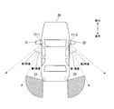
- FIG. 2 is a diagram illustrating an imaging range of the rear side imaging unit 11 in the present embodiment.
- the rear side imaging unit 11-1 is a wide-angle lens camera and is provided on the left side mirror 31 of the vehicle 30. Then, the rear side imaging unit 11-1 images a predetermined angle range on the left rear side of the vehicle 30.
- the range of the predetermined angle captured by the rear side imaging unit 11-1 includes an area including the left adjacent lane.
- the rear side imaging unit 11-1 has a first angle range that is an equivalent field angle range of the side mirror 31 and a blind angle range of the side mirror 31. An area including the range of the second angle is imaged.
- the range of the first angle is a range of angles up to 30 degrees, for example, with the rear of the vehicle 30 as a reference.
- the range of the second angle is, for example, a range of angles up to 30 degrees with the first angle as a reference. Therefore, for example, the rear side imaging unit 11-1 images a range of angles up to 60 degrees to the left rear side with the left rear of the vehicle 30 as a reference. The rear side imaging unit 11-1 outputs the captured image to the image processing unit 13.
- an angle range of 30 degrees is as shown in FIG. This is a range of angles widened by a predetermined angle (30 degrees in this case) to the side of the further away direction.
- this is synonymous with the rear and rear side images that are displayed on the side mirrors 31 and 32 and can be confirmed by the driver from the viewpoint of the driver.
- the rear side imaging unit 11-2 is a wide-angle lens camera, and is provided on the right side mirror 32 of the vehicle 30. Then, the rear side imaging unit 11-2 captures a range of a predetermined angle on the right rear side of the vehicle 30.
- the range of the predetermined angle imaged by the rear side imaging unit 11-2 includes an area including the adjacent lane on the right side.
- the rear side imaging unit 11-2 has a first angle range that is an equivalent field angle range of the side mirror 32 and a blind angle range of the side mirror 32. An area including the range of the second angle is imaged.
- the rear side imaging unit 11-2 images a range of angles up to 60 degrees to the right rear side with the right rear of the vehicle 30 as a reference.
- the rear side imaging unit 11-2 outputs the captured image to the image processing unit 13.
- an infrared camera, a high-sensitivity camera, or a camera capable of shooting in a dark part or darkness as the rear side imaging unit 11 it is possible to obtain a good video field even at night.
- the detection unit 10 (detection units 10-1 and 10-2) is attached to the rear of the vehicle 30 and detects a subsequent vehicle existing behind the vehicle 30.
- the detection unit 10-1 detects the following vehicle existing on the left rear side.
- the detection unit 10-2 detects the following vehicle existing on the right rear side.
- the detection unit 10 detects a succeeding vehicle that exists on the rear side using a millimeter wave radar.
- the detection part 10 should just be able to detect the following vehicle which exists in the rear side of the vehicle 30, and is not specifically limited to the detection method.
- the detection unit 10 uses a BSD (Blind Spot Detection) system, an LCA (Lane Change Alert) system, an RCTA (Rear Cross Cross Traffic Alert), or the like that uses a millimeter wave radar to detect the following vehicle. 10 may detect the following vehicle existing behind the vehicle 30 by using a function of recognizing the relative distance between the host vehicle and the object imaged by the camera by the image processing unit 13, The following vehicle may be detected by a laser radar. The succeeding vehicle existing on the rear side is, for example, the following vehicle existing at the second angle in the left and right adjacent lanes.
- the detection unit 10-1 detects a vehicle that exists in the left second angle range (or enters the second angle range) that is the blind spot of the side mirror 31.
- the detection unit 10-2 detects a vehicle that exists in the right second angle range (or enters the second angle range), which is the blind spot of the side mirror 32.
- the detection units 10-1 and 10-2 each detect a subsequent vehicle existing behind the vehicle 30, the detection units 10-1 and 10-2 output a detection signal indicating that the subsequent vehicle has been detected to the image processing unit 13.
- the detection unit 10 detects the subsequent vehicle existing at the first angle in the left and right adjacent lanes, and outputs a detection signal indicating that the subsequent vehicle has been detected to the image processing unit 13. May be. That is, the detection unit 10 may detect a subsequent vehicle before the subsequent vehicle enters the blind spot of the side mirror 32 and output a detection signal indicating that the subsequent vehicle has been detected to the image processing unit 13.
- the image processing unit 13 extracts a first image that is an image corresponding to the range of the first angle from the image captured by the rear side imaging unit 11-1. Then, the image processing unit 13 causes the display unit 141 to display the first image extracted from the image captured by the rear side imaging unit 11-1.
- the image processing unit 13 outputs the second image including at least the second angle range larger than the first angle to the rear side imaging unit 11- 1 is extracted from the image picked up by 1. Then, the image processing unit 13 causes the display unit 141 to display the extracted first image and second image. In this case, for example, the image processing unit 13 displays the second image on the display unit 141 so as to be continuous with the first image.
- the driver can grasp the position of the subsequent vehicle relative to the vehicle 30 while ensuring the visibility of the subsequent vehicle by checking the display unit 141.
- the range of the second angle that is larger than the first angle is a range of angles that are expanded to the side in the direction away from the host vehicle rather than the range of the first angle.
- the second image on the left side as viewed from the driver is displayed on the left side of the first image on the left side.
- the image processing unit 13 extracts a first image that is an image corresponding to the range of the first angle from the image captured by the rear side imaging unit 11-2. Then, the image processing unit 13 causes the display unit 142 to display the first image extracted from the image captured by the rear side imaging unit 11-2.
- the image processing unit 13 outputs the second image including at least the second angle range larger than the first angle to the rear side imaging unit 11- 2 is extracted from the image captured in step 2. Then, the image processing unit 13 causes the display unit 142 to display the extracted first image and second image. In this case, the image processing unit 13 causes the display unit 142 to display the second image so as to be continuous with the first image. The second image on the right side as viewed from the driver is displayed on the right side of the first image on the right side.
- Each unit of the image processing unit 13 may be realized by hardware, may be realized by software, or may be realized by a combination of hardware and software.
- the display unit 141 is provided inside the vehicle 30.
- the display unit 141 displays an image captured by the rear side imaging unit 11-1.
- the display unit 142 is provided inside the vehicle 30.
- the display unit 142 displays the image captured by the rear side imaging unit 11-2.
- the display unit 141 includes a first display area 141a for displaying the first image and a second display area 141b for displaying the second image.
- the display unit 142 includes a first display area 142a that displays a first image and a second display area 142b that displays a second image.
- the display units 141 and 142 may be separated from each other, or may be configured as one display unit.
- the display screens of the first display area 142a and the second display area 142b of the display unit 142 according to the present embodiment will be described with reference to FIGS.
- the display screens of the first display area 141a and the second display area 141b and the display screens of the first display area 142a and the second display area 142b differ only in the images displayed on the left and right of the vehicle 30. The contents are the same. Therefore, description of the display screens of the first display area 141a and the second display area 141b is omitted.
- FIG. 3 is a diagram showing a display screen of the display unit 142 when there is no subsequent vehicle on the right rear side of the vehicle 30.
- the detection unit 10-2 since there is no following vehicle at the first angle or the second angle on the right rear side of the vehicle 30, the detection unit 10-2 does not output a detection signal. Therefore, the display unit 142 displays the first image in the image captured by the rear side imaging unit 11-2 in the first display area 142a.
- the display unit 142 does not display the image captured by the rear side imaging unit 11-2 in the second display area 142b.
- the display unit 142 may black out the second display area 142b, may have a blue screen, may have an indicator function to notify the driver of the presence of the following vehicle, road traffic information, etc.
- the guide information may be displayed.
- the display unit 142 displays the same range as the angle of view of the side mirror 32 only in the first display area 142a when there is no following vehicle in the blind spot of the side mirror 32.
- FIG. 4 is a diagram showing a display screen of the display unit 142 when the succeeding vehicle 100 exists in the far right rear side of the vehicle 30.
- the following vehicle 100 shown in FIG. 4 exists far to the right rear side of the vehicle 30, and it is assumed that there is no safety problem even if the vehicle 30 changes lanes to the lane on the right.
- the detection unit 10-2 does not output a detection signal.
- the display unit 142 displays the first image in the image captured by the rear side imaging unit 11-2 in the first display area 142a.
- the display unit 142 does not display the image captured by the rear side imaging unit 11-2 in the second display area 142b.
- FIG. 5 is a diagram illustrating a display screen of the display unit 142 when the succeeding vehicle 100 exists on the right rear side of the vehicle 30.
- the detecting unit 10-2 detects the following vehicle 100. Is detected, and a detection signal is output to the image processing unit 13. Then, when the detection signal is acquired from the detection unit 10-2, the image processing unit 13 extracts the second image in the image captured by the rear side imaging unit 11-2, and displays the extracted second image. Output to the unit 142.
- the display unit 142 displays the first image in the image captured by the rear side imaging unit 11-2 in the first display region 141a and displays the second image in the second display region 142b.
- the display unit 142 displays the second image in the second display area 142b so as to be continuous with the first image.
- the first image and the second image are images having the same scale. That is, the display unit 142 widens the angle of view while maintaining the scale of the image to be displayed when the succeeding vehicle 100 exists on the right rear side of the vehicle 30. Thereby, the driver can maintain the sense of distance of the following vehicle 100 with respect to the vehicle 30.
- the display unit 142 displays the first image in the first display region 142a and the side mirror 32 in the second display region 142b. Displays the range of the blind spot.
- FIG. 6 is a diagram showing a display screen of the display unit 142 when the succeeding vehicle 100 exists on the right rear side of the vehicle 30.
- the detection unit 10-2 continues to output the detection signal to the image processing unit 13. Therefore, the display unit 142 displays the first image in the image captured by the rear side imaging unit 11-2 in the first display region 141a and displays the second image in the second display region 142b. That is, the display unit 142 displays the first image in the first display area 142a and the subsequent vehicle 100 when the subsequent vehicle enters the range that has been the blind spot of the driver (the blind spot of the side mirror 32) in the past.
- the display unit 142 sets the second image to the second display area 142 b so as to be continuous with the first image including the vehicle 30. Thereby, the position of the succeeding vehicle relative to the vehicle 30 can be grasped while ensuring the visibility of the succeeding vehicle 100.
- the display unit 142 stops the display of the second image in the second display region 142b, blackouts the second display region 142b, Display guidance information such as blue screen, indicator function, or road traffic information. Thereby, the display of an unnecessary 2nd image is reduced and the troublesomeness to a driver is reduced.
- the case where the output of the detection signal from the detection unit 10-2 is stopped is a case where the succeeding vehicle 100 enters outside the detection range of the detection unit 10-2.
- the troublesomeness to the driver is a sense of incongruity that the driver feels due to the changing speed difference of the captured image (captured scenery) projected on the first image and the second image. Normally, an image displayed in one display area has a higher speed of image transition as it goes to the side away from the vehicle.
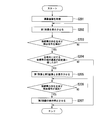
- FIG. 7 is a diagram for explaining the flow of processing of the image processing unit 13 in the present embodiment.
- a case where the following vehicle 100 does not exist on the rear side of the vehicle 30 will be described as an example.
- the image processing unit 13 acquires an image captured by the rear side imaging unit 11 (step S101).
- the image processing unit 13 extracts a first image that is an image corresponding to the range of the first angle from the image captured by the rear side imaging unit 11.
- the image processing unit 13 causes the display device 14 to display the first image extracted from the image captured by the rear side imaging unit 11 (step S102).
- the image processing unit 13 extracts a first image that is an image corresponding to the range of the first angle from the image captured by the rear side imaging unit 11-1.
- the image processing unit 13 displays the first image extracted from the image captured by the rear side imaging unit 11-1 in the first display area 141a of the display unit 141.
- the image processing unit 13 extracts a first image that is an image corresponding to the range of the first angle from the image captured by the rear side imaging unit 11-2. Then, the image processing unit 13 displays the first image extracted from the image captured by the rear side imaging unit 11-2 in the first display area 142a of the display unit 142. At this time, the image processing unit 13 may black out the second display areas 141b and 142b, may have a blue screen, or may have an indicator function for notifying the driver of the presence of the following vehicle. Guidance information such as road traffic information may be displayed.
- the image processing unit 13 determines whether a detection signal is acquired from the detection unit 10 (step S103).
- the image processing unit 13 extracts the first image and the second image in the second angle range from the image captured by the rear side imaging unit 11. Is displayed on the display device 14 (step S104).
- the image processing unit 13 extracts the second image from the image captured by the rear side imaging unit 11-1.
- the image processing unit 13 displays the first image in the first display area 141a and displays the second image in the second display area 141b.
- the image processing unit 13 extracts the second image from the image captured by the rear side imaging unit 11-2.
- the image processing unit 13 displays the first image in the first display area 142a and displays the second image in the second display area 142b.
- the image processing unit 13 executes the process of step S102 when the detection signal is not acquired from the detection unit 10.
- the image processing unit 13 determines whether or not the detection signal output from the detection unit 10 has disappeared (step S105).
- the image processing unit 13 stops the display of the second image (step S106). For example, when the detection signal output from the detection unit 10-1 disappears, the image processing unit 13 stops displaying the second image in the second display region 141b and blacks out the second display region 141b. Display guidance information such as blue screen, indicator function, or road traffic information.
- the image processing unit 13 stops displaying the second image in the second display region 142b, blacks out the second display region 142b, and performs a blue screen. , Indicator function, or guide information such as road traffic information is displayed. Note that the image processing unit 13 executes the process of step S105 when the detection signal output from the detection unit 10 has not disappeared.
- the vehicle monitoring system 1 includes the detection unit 10 that detects a vehicle that exists on the rear side of the host vehicle, and the rear side that captures a range of a predetermined angle on the rear side of the host vehicle. From the imaging unit 11, display units 141 and 142 that are provided inside the host vehicle and display images captured by the rear side imaging unit 11, and images within a predetermined angle range captured by the rear side imaging unit 11. An image processing unit 13 that extracts the first image in the first angle range with reference to the rear of the host vehicle and displays the first image on the display units 141 and 142.
- the image processing unit 13 includes a first image and a range of a second angle larger than the first angle with reference to the rear from the image of the predetermined angle range.
- the second image is extracted and displayed on the display units 141 and 142.
- the display device 14 displays an image equivalent to the angle of view of the side mirror in the first display area. Thereby, it is possible to reduce a sense of incongruity given to the driver (for example, a difference in appearance due to a mirror mounted on a conventional side mirror and an image, a feeling of speed, etc.). Further, the display device 14 sets the second image as the second display area so as to be continuous with the first image. As a result, the driver can display the host vehicle on the first image in the first display area, so that the position of the succeeding vehicle 100 relative to the vehicle 30 that is the host vehicle can be more easily grasped.
- the angle of view of the side mirror is a range of the image displayed on the side mirror that can be confirmed by the driver, and an image having an angle of view equivalent to the angle of view of the side mirror is displayed in the first display area. Is displayed. Further, the angle of view of the side mirror is usually set to at least (at least) 25 degrees to 30 degrees, but this is arbitrarily set by the vehicle. In addition, the first and second display areas can be arbitrarily moved in the display direction like a conventional side mirror.
- the display device 14 displays the first image and the second image as images of the same scale. That is, the display unit 142 widens the angle of view while maintaining the scale of the image to be displayed when the succeeding vehicle 100 exists on the right rear side of the vehicle 30. Thereby, even when the second image is displayed in the second display area, the driver can display the host vehicle in the first image in the first display area. Further, the driver can display the first image in the first display area. The scale and perspective of the image displayed in the second image in the second display area can be kept unchanged. Therefore, it is possible to eliminate the distortion and uncomfortable feeling of the displayed image and maintain the sense of distance of the succeeding vehicle 100 relative to the vehicle 30.
- the displayed subject is reduced, but in the present invention, since the first display area and the second display area are provided with a plurality of display areas, The first image and the second image can have the same scale.
- the display device 14 displays the first image only in the first display area, but the present invention is not limited to this.
- the display device 14 displays the second image in the second display area if the driver's troublesomeness can be reduced by making the brightness and saturation of the second display area sufficiently lower than the first display area. May be.
- the second image may be always displayed in the second display area by providing a switch or the like that allows the driver to arbitrarily select ON / OFF of the display in the second display area.
- the display device 14 may blink the second display area in a flashing manner when a succeeding vehicle exists on the right rear side of the vehicle 30 (acquisition of a detection signal). . Thereby, the driver can grasp that the following vehicle is approaching from the adjacent lane.
- the vehicle monitor system 1 further includes a sound generator, and when a succeeding vehicle is present on the right rear side of the vehicle 30 (a detection signal is acquired), a warning sound or sound is output. The approach of the following vehicle may be notified to the driver. Further, the subsequent vehicle may be displayed in an enlarged manner by displaying the second image as an enlarged image. Further, an indicator lamp or the like may be blinked by an indicator function that informs the driver of the presence of the following vehicle. That is, the display device 14 may notify the driver of the approach of the following vehicle by displaying the second display area in a display mode different from the display mode of the first display area, and the display mode is limited. Not.
- the image processing unit 13 determines the vehicle 30 from the image in the range of a predetermined angle captured by the rear side imaging unit 11. The relative position of the following vehicle 100 may be calculated. Then, the image processing unit 13. The range of the second angle may be determined based on the calculated relative position. In addition, the image processing unit 13 recognizes and calculates the relative position (relative distance) between the vehicle 30 and the following vehicle 100 imaged by the rear side imaging unit 11, and the like. You may make it detect the subsequent vehicle 100 which exists. That is, the function of the detection unit 10 may be performed by the rear side imaging unit 11 and the image processing unit 13.
- the image processing unit 13 may determine the second angle range according to the relative speed of the following vehicle 100.
- the vehicle monitor system 1 may further include a switch for displaying the second image in the second display area. Thereby, the user can confirm the image of the second angle at a desired timing.
- the image processing unit 13 may display the second image in the second display area when the steering of the vehicle 30 is rotated by a predetermined angle or more.
- the case where the steering of the vehicle 30 is rotated more than a predetermined angle is a case where the vehicle 30 changes the lane to the adjacent lane by the driver.
- the driver can change the lane of the vehicle 30 more safely while confirming the second image displayed in the second display area.
- the second image may be displayed in the second display area when the operation of the direction indicator is detected or when both the operation of the direction indicator and the steering operation are detected.
- the display device 14 may be provided on the center panel of the vehicle 30. This makes it possible to confirm the blind spots of the side mirrors 31 and 32 while the vehicle 30 is traveling without impairing the field of vision ahead of the driver.
- the vehicle monitor system 1 may further include a rear imaging unit that images the rear of the vehicle 30.
- FIG. 8 is a diagram illustrating an arrangement position of the display device 14 when the vehicle monitoring system 1 further includes a rear imaging unit that images the rear of the vehicle 30.
- the display device 14 is provided on the center panel of the vehicle 30.
- the display device 14 displays the images captured by the rear side imaging units 11-1 and 11-2 and the rear imaging unit under the control of the image processing unit 13 so that the images are continuous.
- the display device 14 causes the display device 14 to display a panoramic image obtained by combining the images captured by the rear side imaging units 11-1 and 11-2 and the image captured by the rear imaging unit.
- the display device 14 that displays images from the rear of the vehicle 30 to the blind spots of the side mirrors 31 and 32 on the rear side on the center panel, it is possible to concentrate the indirect view information on the center panel.
- the burden caused by the driver's neck swing and eye movement can be reduced.
- the display device 14 may be arranged on a meter panel in addition to the center panel. Furthermore, as long as the visibility in front of the driver is not impaired, a separate monitor may be provided as the display device 14, and the first display area and the second display area may be used as a rearview mirror or a windshield. A head-up display or the like may be used. By doing so, the forward visual field is not impaired, and the movement of the driver's line of sight can be further reduced.
- the image processing unit 13 marks subsequent vehicles (including four wheels, two wheels, and bicycles) in the images captured by the rear side imaging units 11-1 and 11-2 and the rear imaging unit. By doing so, the driver may be informed of the approach of the following vehicle.
- the first image and the second image may have partial areas overlapping or different areas.
- the rear side imaging unit is provided in the side mirror.
- the present invention is not limited to this, and it may be provided inside and outside the vehicle body. That is, since it is only necessary to display the rear side as the first image and the second image with respect to the host vehicle, the installation position of the rear side imaging unit is not limited. Moreover, the presence or absence of a side mirror with respect to the host vehicle is not limited.
- the first image may be always displayed in the first display area when necessary, and the second image may be selectively displayed in the second display area depending on the situation.
- the time when the first image is displayed is when the driver is in the vehicle, when the opening / closing of the vehicle door for the passenger to enter is detected, or when the ignition of the vehicle is turned on.
- the timer may be activated after detecting that the driver has exited the vehicle, the passenger getting off the vehicle, turning off the ignition, or the like, and the output to the display unit may be stopped after a predetermined time.
- the wide-angle lens camera is shown.
- the present invention is not limited to this, and the captured image may be displayed as it is with a camera that can capture the necessary angle.
- the number of cameras as the rear side imaging unit is not limited, and a range of a predetermined angle including the first angle and the second angle may be captured by one camera, or two or more cameras may be used. You may make it image the range of a predetermined angle.
- an image equivalent to the angle of view of the side mirror is displayed in the first display area, but the presence or absence of the side mirror is not limited here. That is, even if the vehicle is not equipped with a side mirror, the angle of view to be displayed in the first display area can be set to an equivalent angle assuming that the side mirror is temporarily installed. Further, the angle of view can be arbitrarily set in the first display area and the second display area. Therefore, the angle of view to be displayed can be made different between the first display area and the second display area.
- the image processing unit 13 causes the display device 14 to display the first image and the second image according to the relative speed of the following vehicle 100.
- the image processing unit 13 may display the first image and the second image on the display device 14 when the relative speed of the subsequent vehicle 100 with respect to the host vehicle reaches a set value.
- the second image is not displayed when the subsequent vehicle stops or when the speed of the subsequent vehicle is slow and there is no problem in changing the lane safely. Thereby, an unnecessary second image can be prevented, and the troublesomeness of the driver can be reduced.
- the method for acquiring the relative speed of the succeeding vehicle 100 with respect to the host vehicle is not particularly limited.
- the relative speed may be determined based on the relative distance between the vehicle and the object imaged by the camera, or may be determined using a known technique.
- FIG. 9 is a diagram illustrating the processing flow of the image processing unit 13 in the present modification. As an initial condition, a case where the following vehicle 100 does not exist on the rear side of the vehicle 30 will be described as an example.
- the image processing unit 13 acquires an image captured by the rear side imaging unit 11 (step S201).
- the image processing unit 13 extracts a first image that is an image corresponding to the range of the first angle from the image captured by the rear side imaging unit 11.
- the image processing unit 13 displays the first image extracted from the image captured by the rear side imaging unit 11 on the display device 14 (step S202).
- the image processing unit 13 extracts a first image that is an image corresponding to the range of the first angle from the image captured by the rear side imaging unit 11-1.
- the image processing unit 13 displays the first image extracted from the image captured by the rear side imaging unit 11-1 in the first display area 141a of the display unit 141.
- the image processing unit 13 extracts a first image that is an image corresponding to the range of the first angle from the image captured by the rear side imaging unit 11-2. Then, the image processing unit 13 displays the first image extracted from the image captured by the rear side imaging unit 11-2 in the first display area 142a of the display unit 142. At this time, the image processing unit 13 may black out the second display areas 141b and 142b, may have a blue screen, or may have an indicator function for notifying the driver of the presence of the following vehicle. Guidance information such as road traffic information may be displayed.
- the image processing unit 13 determines whether or not a detection signal has been acquired from the detection unit 10 (step S203). When the image processing unit 13 does not acquire a detection signal from the detection unit 10, the image processing unit 13 performs the process of step S202.
- the image processing unit 13 determines whether or not the relative speed of the following vehicle with respect to the host vehicle has reached a set value.
- the image processing unit 13 sets the second angle in the second angle range from the first image and the image captured by the rear side imaging unit 11.
- the image is extracted and displayed on the display device 14 (step S205).
- the image processing unit 13 does not display the second image or stops displaying the second image when the relative speed of the following vehicle with respect to the host vehicle has not reached the set value.
- the image processing unit 13 determines whether or not the detection signal output from the detection unit 10 has disappeared (step S206). When the detection signal output from the detection unit 10 disappears, the image processing unit 13 stops the display of the second image (step S207). For example, when the detection signal output from the detection unit 10-1 disappears, the image processing unit 13 stops displaying the second image in the second display region 141b and blacks out the second display region 141b. Display guidance information such as blue screen, indicator function, or road traffic information. When the detection signal output from the detection unit 10-2 disappears, the image processing unit 13 stops displaying the second image in the second display region 142b, blacks out the second display region 142b, and performs a blue screen. , Indicator function, or guide information such as road traffic information is displayed. Note that the image processing unit 13 executes the process of step S206 when the detection signal output from the detection unit 10 has not disappeared.
- the image processing unit 13 in the above-described embodiment may be realized by a computer.
- a program for realizing this function may be recorded on a computer-readable recording medium, and the program recorded on this recording medium may be read into a computer system and executed.
- the “computer system” includes an OS and hardware such as peripheral devices.
- the “computer-readable recording medium” refers to a storage device such as a flexible medium, a magneto-optical disk, a portable medium such as a ROM or a CD-ROM, and a hard disk incorporated in a computer system.
- the “computer-readable recording medium” dynamically holds a program for a short time like a communication line when transmitting a program via a network such as the Internet or a communication line such as a telephone line.
- a volatile memory inside a computer system serving as a server or a client in that case may be included and a program held for a certain period of time.
- the program may be a program for realizing a part of the above-described functions, and may be a program capable of realizing the functions described above in combination with a program already recorded in a computer system. It may be realized using a programmable logic device such as an FPGA (Field Programmable Gate Array).
- FPGA Field Programmable Gate Array
Landscapes
- Engineering & Computer Science (AREA)
- Multimedia (AREA)
- Mechanical Engineering (AREA)
- Physics & Mathematics (AREA)
- General Physics & Mathematics (AREA)
- Signal Processing (AREA)
- Theoretical Computer Science (AREA)
- Traffic Control Systems (AREA)
- Closed-Circuit Television Systems (AREA)
Abstract
後続車両の視認性を確保しながら、自車両に対する後続車両の位置を把握可能な車両モニタシステムを提供する。 自車両の後側方に存在する車両を検出する検出部と、前記自車両の後側方の所定角度の範囲を撮像する後側方撮像部と、前記自車両の内部に設けられ、前記後側方撮像部が撮像した画像を表示する表示部と、前記後側方撮像部により撮像された前記所定角度の範囲の画像から、前記自車両の後方を基準として第1角度の範囲の第1画像を抽出して前記表示部に表示させる画像処理部と、を備え、前記画像処理部は、前記検出部により前記車両が検出された場合には、前記第1画像と、前記所定角度の範囲の画像から前記後方を基準として前記第1角度よりも大きい第2角度の範囲の第2画像と、を抽出して前記表示部に表示させる。
Description
本発明は、車両モニタシステムに関する。
従来より、車両を運転するドライバの死角を減らすために、車両のフロントドアの上部などにサイドミラーが取り付けられ、それにより車両の側方領域を映すことができる。また、ドライバは、サイドミラーを自車両に対して外側に向けることで、後方及び後続車両への視認性を向上させることができる。
しかしながら、サイドミラーを自車両に対して外側に向けると、サイドミラーに自車両の側面が映らなくなってしまう。その結果、自車両に対する後続車両の位置が把握しづらくなり、安全に車線変更等の動作ができなくなる可能性がある。
本発明は、このような事情に鑑みてなされたもので、その目的は、後方及び後続車両への視認性を確保しながら、自車両に対する後続車両の位置を把握可能な車両モニタシステムを提供することである。
本発明の一態様は、自車両の後側方に存在する車両を検出する検出部と、前記自車両の後側方の所定角度の範囲を撮像する後側方撮像部と、前記自車両の内部に設けられ、前記後側方撮像部が撮像した画像を表示する表示部と、前記後側方撮像部により撮像された前記所定角度の範囲の画像から、前記自車両の後方を基準として第1角度の範囲の第1画像を抽出して前記表示部に表示させる画像処理部と、を備え、前記画像処理部は、前記検出部により前記車両が検出された場合には、前記第1画像と、前記所定角度の範囲の画像から前記後方を基準として前記第1角度よりも大きい第2角度の範囲を含む第2画像と、を抽出して前記表示部に表示させる車両モニタシステムである。
また、本発明の一態様は、車両モニタシステムであって、前記画像処理部は、前記検出部により前記車両が検出された場合には、前記第1画像と一続きになるように前記第2画像を前記表示部に表示させる。
また、本発明の一態様は、車両モニタシステムであって、前記第1画像と前記第2画像とは同一のスケールの画像である。
また、本発明の一態様は、車両モニタシステムであって、前記表示部は、前記第1画像を表示する第1表示領域と、前記第2画像を表示する第2表示領域と、を備え、前記表示部は、前記検出部により前記車両が検出された場合には、前記第2表示領域を前記第1表示領域の表示態様とは異なる表示態様で表示させる。
また、本発明の一態様は、車両モニタシステムであって、前記後側方撮像部は、前記自車両に取り付けられたサイドミラーに備えられ、前記第1角度は、前記サイドミラーの同等の画角の範囲であり、前記第2角度は、前記サイドミラーの死角の範囲を少なくとも含む。
また、本発明の一態様は、車両モニタシステムであって、前記画像処理部は、前記検出部により前記車両が検出された場合には、前記後側方撮像部により撮像された前記所定角度の範囲の画像から、前記自車両に対する前記車両の相対位置を算出し、前記算出した前記相対位置に基づいて前記第2角度を決定する。
また、本発明の一態様は、車両モニタシステムであって、前記表示部は、前記自車両のセンターパネルに設けられる。
また、本発明の一態様は、車両モニタシステムであって、前記画像処理部は、前記後側方の画像と前記後方の画像とが一続きになるように前記表示部に表示させる。
以上説明したように、本発明によれば、後続車両の視認性を確保しながら、自車両に対する後続車両の位置を把握可能な車両モニタシステムを提供することができる。
以下、発明の実施の形態を通じて本発明を説明するが、以下の実施形態は特許請求の範囲にかかる発明を限定するものではない。また、実施形態の中で説明されている特徴の組み合わせの全てが発明の解決手段に必須であるとは限らない。なお、図面において、同一又は類似の部分には同一の符号を付して、重複する説明を省く場合がある。
実施形態における車両モニタシステムは、車両に搭載され、後側方撮像部を用いて撮像された自車両の後側方の広角画像からサイドミラー相当の第1画像を切り出し、切り出した第1画像を自車両内の表示部に表示する。また、車両モニタシステムは、隣接車線から後続車両が近づいてきた場合に、サイドミラーの死角となる範囲の第2画像を上記広角画像から切り出し、その切り出した第2画像を第1画像と一続きになるように表示部に表示する。これにより、後続車両の視認性を確保しながら、自車に対する後続車両の位置を把握可能である。
以下、実施形態の車両モニタシステムを、図面を用いて説明する。
以下、実施形態の車両モニタシステムを、図面を用いて説明する。
図1は、本実施形態における車両モニタシステム1の概略構成の一例を示す図である。 図1に示すように、車両モニタシステム1は、検出部10(検出部10-1,10-2)、後側方撮像部11(後側方撮像部11-1,11-2)、画像処理部13及び表示装置14(表示部141,142)を備える。
後側方撮像部11(後側方撮像部11-1,11-2)は、車両30の後側方の所定角度の範囲を撮像する。図2は、本実施形態における後側方撮像部11の撮像範囲を示す図である。
図2に示すように、例えば、後側方撮像部11-1は、広角レンズのカメラであって、車両30の左側のサイドミラー31に設けられている。そして、後側方撮像部11-1は、車両30の左後側方の所定角度の範囲を撮像する。例えば、後側方撮像部11-1が撮像する所定角度の範囲とは、左側の隣接車線が含まれる領域を有する。具体的には、図2に示すように、後側方撮像部11-1は、サイドミラー31の同等の画角の範囲である第1角度の範囲と、サイドミラー31の死角の範囲である第2角度の範囲と、を含む領域を撮像する。第1角度の範囲は、車両30の後方を基準として、例えば、30度までの角度の範囲である。第2角度の範囲は、第1角度を基準として、例えば、30度までの角度の範囲である。したがって、例えば、後側方撮像部11-1は、車両30の左後方を基準として、左後側方へ60度までの角度の範囲を撮像する。後側方撮像部11-1は、撮像した画像を画像処理部13に出力する。ここで、第1角度の範囲としての後方を基準として例えば30度の角度の範囲とは、図2に示すように、自車両の側面から、サイドミラー31,32を基点として該側面から自車両より離れる方向の側方へ所定角度(ここでは30度)広げた角度の範囲をいう。また、これは、ドライバ視点にて、サイドミラー31,32に映しだされドライバが確認することのできる後方および後側方像と同義である。
例えば、後側方撮像部11-2は、広角レンズのカメラであって、車両30の右側のサイドミラー32に設けられている。そして、後側方撮像部11-2は、車両30の右後側方の所定角度の範囲を撮像する。例えば、後側方撮像部11-2が撮像する所定角度の範囲とは、右側の隣接車線が含まれる領域を有する。具体的には、図2に示すように、後側方撮像部11-2は、サイドミラー32の同等の画角の範囲である第1角度の範囲と、サイドミラー32の死角の範囲である第2角度の範囲と、を含む領域を撮像する。例えば、後側方撮像部11-2は、車両30の右後方を基準として、右後側方へ60度までの角度の範囲を撮像する。後側方撮像部11-2は、撮像した画像を画像処理部13に出力する。なお、後側方撮像部11として赤外線カメラや高感度カメラ、暗部や暗闇の撮影に対応できるカメラを用いることにより、夜間でも良好な映像視界を得ることが可能である。
検出部10(検出部10-1,10-2)は、車両30の後方に取り付けられており、車両30の後側方に存在する後続車両を検出する。検出部10-1は、左後側方に存在する後続車両を検出する。検出部10-2は、右後側方に存在する後続車両を検出する。例えば、検出部10(検出部10-1,10-2)は、ミリ波レーダーを用いて後側方に存在する後続車両を検出する。ただし、検出部10は、車両30の後側方に存在する後続車両を検出できればよく、検出方法には特に限定されない。例えば、検出部10は、ミリ波レーダーを用いて後続車両を検知するBSD(Blind Spot Detection)システムやLCA(Lane Change Alert)システム、RCTA(Rear Cross Traffic Alert)等を用いて、また、検出部10は、自車両とカメラにより撮像された対象との相対距離を画像処理部13にて認識する機能等を用いて、車両30の後側方に存在する後続車両を検出してもよいし、レーザレーダにより後続車両を検出してもよい。後側方に存在する後続車両とは、例えば、左右の隣接車線において、第2角度に存在する後続車両である。すなわち、例えば、検出部10-1は、サイドミラー31の死角となる左側の第2角度の範囲に存在する(又は第2角度の範囲に進入する)車両を検知する。検出部10-2は、サイドミラー32の死角となる右側の第2角度の範囲に存在する(又は第2角度の範囲に進入する)車両を検知する。検出部10-1,10-2は、それぞれ、車両30の後側方に存在する後続車両を検出すると、その後続車両を検出したことを示す検出信号を画像処理部13に出力する。なお、安全を考慮して、検出部10は、左右の隣接車線において、第1角度に存在する後続車両を検出し、その後続車両を検出したことを示す検出信号を画像処理部13に出力してもよい。すなわち、検出部10は、サイドミラー32の死角に後続車両が進入する前に後続車両を検出し、その後続車両を検出したことを示す検出信号を画像処理部13に出力してもよい。
画像処理部13は、後側方撮像部11-1により撮像された画像から、第1角度の範囲に対応する画像である第1画像を抽出する。そして、画像処理部13は、後側方撮像部11-1により撮像された画像から抽出した第1画像を表示部141に表示させる。
ただし、画像処理部13は、検出部10-1から検出信号が出力された場合には、第1角度よりも大きい第2角度の範囲を少なくとも含む第2画像を、後側方撮像部11-1により撮像された画像から抽出する。そして、画像処理部13は、抽出した第1画像と第2画像とを表示部141に表示させる。この場合に、例えば、画像処理部13は、第1画像と一続きになるように第2画像を表示部141に表示させる。これにより、ドライバは、表示部141を確認することで、後続車両の視認性を確保しながら、車両30に対する後続車両の位置を把握可能である。ここで、第1角度よりも大きい第2角度の範囲とは、第1角度の範囲よりも自車両より離れる方向の側方へ広げた角度の範囲のことである。ドライバから見て左側の第2画像は、左側の第1画像の左側に表示する。
画像処理部13は、後側方撮像部11-2により撮像された画像から、第1角度の範囲に対応する画像である第1画像を抽出する。そして、画像処理部13は、後側方撮像部11-2により撮像された画像から抽出した第1画像を表示部142に表示させる。
ただし、画像処理部13は、検出部10-2から検出信号が出力された場合には、第1角度よりも大きい第2角度の範囲を少なくとも含む第2画像を、後側方撮像部11-2により撮像された画像から抽出する。そして、画像処理部13は、抽出した第1画像と第2画像とを表示部142に表示させる。この場合に、画像処理部13は、第1画像と一続きになるように第2画像を表示部142に表示させる。ドライバから見て右側の第2画像は、右側の第1画像の右側に表示する。
なお、画像処理部13の各部は、ハードウェアにより実現されてもよく、ソフトウェアにより実現されてもよく、ハードウェアとソフトウェアとの組み合わせにより実現されてもよい。
表示部141は、車両30の内部に設けられている。表示部141は、後側方撮像部11-1が撮像した画像を表示する。表示部142は、車両30の内部に設けられている。表示部142は、後側方撮像部11-2が撮像した画像を表示する。
表示部141は、第1画像を表示する第1表示領域141aと、第2画像を表示する第2表示領域141bと、を備える。表示部142は、第1画像を表示する第1表示領域142aと、第2画像を表示する第2表示領域142bと、を備える。なお、表示部141,142は、互いに分離されていてもよいし、1つの表示部として構成されてもよい。
以下に、本実施形態における表示部142の第1表示領域142a,第2表示領域142bの表示画面について、図3~図6を用いて説明する。なお、第1表示領域141a,第2表示領域141bの表示画面と、第1表示領域142a,第2表示領域142bの表示画面とは、表示する画像が車両30の左右で異なるのみであり、表示内容は同様である。したがって、第1表示領域141a,第2表示領域141bの表示画面については、説明を省略する。
図3は、車両30の右後側方に後続車両が存在していない場合の表示部142の表示画面を示す図である。図3に示すように、車両30の右後側方の第1角度又第2角度に後続車両が存在しないため、検出部10-2は、検出信号を出力しない。したがって、表示部142は、後側方撮像部11-2が撮像した画像における第1画像を第1表示領域142aに表示する。そして、表示部142は、第2表示領域142bには、後側方撮像部11-2が撮像した画像を表示しない。例えば、表示部142は、第2表示領域142bをブラックアウトしてもよいし、ブルースクリーンにしてもよいし、後続車両の存在をドライバへ知らせるインジケータ機能を備えてもよいし、道路交通情報等の案内情報を表示してもよい。このように、表示部142は、サイドミラー32の死角に後続車両が存在しない場合には、第1表示領域142aにのみサイドミラー32の画角と同様の範囲を表示する。
図4は、車両30の右後側方の遠方に後続車両100が存在した場合の表示部142の表示画面を示す図である。図4に示す後続車両100は、車両30の右後側方の遠方に存在しており、車両30が右隣の車線に対して車線変更しても安全上問題ないとする。この場合には、検出部10-2は、検出信号を出力しない。図3と同様に、表示部142は、後側方撮像部11-2が撮像した画像における第1画像を第1表示領域142aに表示する。そして、表示部142は、第2表示領域142bには、後側方撮像部11-2が撮像した画像を表示しない。
図5は、車両30の右後側方に後続車両100が存在している場合の表示部142の表示画面を示す図である。図5に示すように、車両30の右後側方に後続車両100が存在する(例えば、第1角度の範囲に後続車両100が存在する)ため、検出部10-2は、その後続車両100の存在を検出し、検出信号を画像処理部13に出力する。そして、画像処理部13は、検出部10-2から検出信号を取得した場合には、後側方撮像部11-2が撮像した画像における第2画像を抽出し、抽出した第2画像を表示部142に出力する。これにより、表示部142は、後側方撮像部11-2が撮像した画像における第1画像を第1表示領域141aに表示するとともに、第2表示領域142bに第2画像を表示する。本実施形態では、表示部142は、第1画像と一続きになるように第2画像を第2表示領域142bに表示する。そして、第1画像と第2画像とは、同じスケールの画像である。すなわち、表示部142は、車両30の右後側方に後続車両100が存在している場合には、表示する画像のスケールを維持したまま、画角を広げる。これにより、ドライバは、車両30に対する後続車両100の距離感を維持できる。このように、表示部142は、車両30の右後側方に後続車両100が存在する場合には、第1表示領域142aに第1画像を表示するとともに、第2表示領域142bにサイドミラー32の死角の範囲を表示する。
図6は、車両30の右後側方に後続車両100が存在している場合の表示部142の表示画面を示す図である。図6に示すように、車両30の右後側方に後続車両100が存在し、且つその後続車両100は、第2角度の範囲に進入している。そのため、検出部10-2は、画像処理部13に対する検出信号の出力を継続する。したがって、表示部142は、後側方撮像部11-2が撮像した画像における第1画像を第1表示領域141aに表示するとともに、第2表示領域142bに第2画像を表示する。すなわち、表示部142は、従来においてドライバの死角(サイドミラー32の死角)であった範囲に、後続車両が進入した場合、第1表示領域142aに第1画像を表示するとともに、その後続車両100が存在するサイドミラー32の死角の範囲の画像を第2表示領域142bに表示する。したがって、ドライバは、第2表示領域142bを確認することで、サイドミラー32の死角に進入した後続車両100の存在を把握することができる。また、図6に示すように、本実施形態では、表示部142は、車両30を含む第1画像と一続きになるように第2画像を第2表示領域142bにする。これにより、後続車両100の視認性を確保しながら、車両30に対する後続車両の位置を把握可能である。
なお、表示部142は、検出部10-2からの検出信号の出力が停止された場合には、第2表示領域142bにおける第2画像の表示を停止し、第2表示領域142bをブラックアウト、ブルースクリーン、インジケータ機能、又は道路交通情報等の案内情報を表示する。これにより、不要な第2画像の表示を削減し、ドライバへのわずらわしさを低減する。検出部10-2からの検出信号の出力が停止された場合とは、後続車両100が検出部10-2の検出範囲外に進入した場合である。ここでドライバへのわずらわしさとは、第1画像と第2画像とに映し出される撮像画像(撮像風景)について、その移り変わる速度差によって生じるドライバの感じる違和感のことである。通常、1つの表示領域に映し出される画像は、車両から離れる方向の側方に向かうにつれ画像の移り変わる速度が速くなる。
以下に、本実施形態における画像処理部13の処理の流れについて、説明する。図7は、本実施形態における画像処理部13の処理の流れについて、説明する図である。なお、初期条件として、車両30の後側方に後続車両100が存在していない場合を例として説明する。
画像処理部13は、後側方撮像部11により撮像された画像を取得する(ステップS101)。画像処理部13は、後側方撮像部11により撮像された画像から、第1角度の範囲に対応する画像である第1画像を抽出する。そして、画像処理部13は、後側方撮像部11により撮像された画像から抽出した第1画像を表示装置14に表示させる(ステップS102)。例えば、画像処理部13は、後側方撮像部11-1により撮像された画像から、第1角度の範囲に対応する画像である第1画像を抽出する。そして、画像処理部13は、後側方撮像部11-1により撮像された画像から抽出した第1画像を表示部141の第1表示領域141aに表示させる。画像処理部13は、後側方撮像部11-2により撮像された画像から、第1角度の範囲に対応する画像である第1画像を抽出する。そして、画像処理部13は、後側方撮像部11-2により撮像された画像から抽出した第1画像を表示部142の第1表示領域142aに表示させる。このとき、画像処理部13は、第2表示領域141b,142bをブラックアウトしてもよいし、ブルースクリーンにしてもよいし、後続車両の存在をドライバへ知らせるインジケータ機能を備えてもよいし、道路交通情報等の案内情報を表示させてもよい。
画像処理部13は、検出部10から検出信号を取得したか否かを判定する(ステップS103)。画像処理部13は、検出部10から検出信号を取得した場合には、上記第1画像と、後側方撮像部11により撮像された画像から第2角度の範囲の第2画像とを抽出し、表示装置14に表示する(ステップS104)。例えば、画像処理部13は、検出部10-1から検出信号を取得した場合には、後側方撮像部11-1により撮像された画像から第2画像とを抽出する。そして、画像処理部13は、第1画像を第1表示領域141aに表示するとともに、第2画像を第2表示領域141bに表示する。画像処理部13は、検出部10-2から検出信号を取得した場合には、後側方撮像部11-2により撮像された画像から第2画像とを抽出する。そして、画像処理部13は、第1画像を第1表示領域142aに表示するとともに、第2画像を第2表示領域142bに表示する。なお、画像処理部13は、検出部10から検出信号を取得しない場合には、ステップS102の処理を実行する。
画像処理部13は、検出部10から出力される検出信号が消失したか否かを判定する(ステップS105)。画像処理部13は、検出部10から出力される検出信号が消失した場合には、第2画像の表示を停止させる(ステップS106)。例えば、画像処理部13は、検出部10-1から出力される検出信号が消失した場合には、第2表示領域141bにおける第2画像の表示を停止し、第2表示領域141bをブラックアウト、ブルースクリーン、インジケータ機能、又は道路交通情報等の案内情報を表示する。画像処理部13は、検出部10-2から出力される検出信号が消失した場合には、第2表示領域142bにおける第2画像の表示を停止し、第2表示領域142bをブラックアウト、ブルースクリーン、インジケータ機能、又は道路交通情報等の案内情報を表示する。なお、画像処理部13は、検出部10から出力される検出信号が消失していない場合には、ステップS105の処理を実行する。
上述したように、本実施形態における車両モニタシステム1は、自車両の後側方に存在する車両を検出する検出部10と、自車両の後側方の所定角度の範囲を撮像する後側方撮像部11と、自車両の内部に設けられ、後側方撮像部11が撮像した画像を表示する表示部141,142と、後側方撮像部11により撮像された所定角度の範囲の画像から、自車両の後方を基準として第1角度の範囲の第1画像を抽出して表示部141,142に表示させる画像処理部13と、を備える。そして、画像処理部13は、検出部10により車両が検出された場合には、第1画像と、所定角度の範囲の画像から後方を基準として第1角度よりも大きい第2角度の範囲を含む第2画像と、を抽出して表示部141,142に表示させる。これにより、車両30のドライバは、表示部141,142を確認することで、後続車両100の視認性を確保しながら、自車両である車両30に対する後続車両100の位置を把握することができる。これにより、ドライバは、車線変更等の動作を安全に実施することができる。
また、上述したように、表示装置14は、第1表示領域に、サイドミラーの画角と同等の画像を表示する。これにより、ドライバに与える違和感(例えば、従来からのサイドミラーに搭載される鏡と、画像とによる見え方の違いやスピード感等)を軽減できる。また、表示装置14は、第1画像と一続きになるように第2画像を第2表示領域にする。これにより、ドライバは、第1表示領域の第1画像に自車両を表示させることができるため、自車両である車両30に対する後続車両100の位置をより把握しやすくなる。ここでサイドミラーの画角とは、ドライバが確認することのできるサイドミラーに映し出される映像の範囲のことであり、第1表示領域には、このサイドミラーの画角と同等の画角の画像を表示する。また、サイドミラーの画角は通常(少なくとも)25度~30度に設定されることが多いが、これは車両によって任意に設定される。また、第1および第2表示領域は、従来のサイドミラーのように、表示させる方向を任意に動かすことができる。
また、上述したように、表示装置14は、第1画像と第2画像とを同じスケールの画像で表示する。すなわち、表示部142は、車両30の右後側方に後続車両100が存在している場合には、表示する画像のスケールを維持したまま、画角を広げる。これにより、ドライバは、第2画像が第2表示領域に表示された場合でも、第1表示領域の第1画像に自車両を表示させることができ、さらに、第1表示領域の第1画像と第2表示領域の第2画像とにおいて映し出される画像の縮尺や遠近感を変わらないようにすることができる。そのため、表示される画像のゆがみや違和感をなくし車両30に対する後続車両100の距離感を維持できる。また、1つの表示領域で画角を広げたものを表示させると、表示される被写体は小さくなるが、本発明では第1表示領域と第2表示領域とで表示領域を複数備えているため、第1画像と第2画像とを同じスケールとすることができる。
また、上述の実施形態において、車両30の右後側方に後続車両が存在しない場合には、表示装置14は、第1表示領域にのみ第1画像を表示したが、これに限定されない。例えば、表示装置14は、第1表示領域よりも第2表示領域の輝度や彩度が十分に低くすることでドライバのわずらわしさを低減可能であれば、第2表示領域に第2画像を表示してもよい。また、第2表示領域の表示のON-OFFをドライバが任意に選択できるスイッチ等を備えることで、第2表示領域に第2画像を常に表示するようにしてもよい。
また、上述の実施形態において、表示装置14は、車両30の右後側方に後続車両が存在する(検出信号を取得している)場合には、第2表示領域をフラッシュ点滅させてもよい。これにより、ドライバは、隣接車線から後続車両が接近していることを把握することができる。また、車両モニタシステム1に、音発生部をさらに備え、車両30の右後側方に後続車両が存在する(検出信号を取得している)場合には、警告音や音声を出力することで、ドライバに対して後続車両の接近を報知してもよい。また、第2画像を拡大画像として表示することで、後続車両を拡大表示させるようにしてもよい。また、後続車両の存在をドライバへ知らせるインジケータ機能により、インジケータランプ等を点滅させてもよい。すなわち、表示装置14は、第2表示領域を第1表示領域の表示態様とは異なる表示態様で表示させることで、ドライバに対して後続車両の接近を報知してもよく、その表示態様は限定されない。
また、上述の実施形態において、画像処理部13は、検出部10により後続車両100が検出された場合には、後側方撮像部11により撮像された所定角度の範囲の画像から、車両30に対する後続車両100の相対位置を算出してもよい。そして、画像処理部13は。算出した相対位置に基づいて第2角度の範囲を決定してもよい。また、車両30と後側方撮像部11により撮像された後続車両100との相対位置(相対距離)を画像処理部13にて認識し算出する機能等を用いて、車両30の後側方に存在する後続車両100を検出するようにしてもよい。つまり、検出部10の機能を後側方撮像部11と画像処理部13とにより担っても良い。
また、上述の実施形態において、画像処理部13は、後続車両100の相対速度に応じて第2角度の範囲を決定してもよい。
また、上述の実施形態において、車両モニタシステム1に第2表示領域に第2画像を表示させるスイッチをさらに設けてもよい。これにより、ユーザは、所望のタイミングで第2角度の画像を確認することができる。
また、上述の実施形態において、画像処理部13は、車両30のステアリングが所定の角度以上に回転した場合には、第2表示領域に第2画像を表示させてもよい。車両30のステアリングが所定の角度以上に回転した場合とは、ドライバにより車両30が隣接車線に車線変更する場合である。これにより、ドライバは、隣接車線に車両30を車線変更する場合に、第2表示領域に表示された第2画像を確認しながら、より安全に車両30を車線変更させることができる。また、方向指示機の作動を検知した場合や方向指示機の作動とステアリング動作との両方を検知した場合などに、第2表示領域に第2画像を表示させるようにしてもよい。
また、上述の実施形態において、表示装置14を車両30のセンターパネルに設けてもよい。これにより、車両30の走行中において、ドライバの前方の視界を損なうことなく、サイドミラー31,32の死角を確認可能となる。
また、上述の実施形態において、車両モニタシステム1は、車両30の後方を撮像する後方撮像部をさらに備えてもよい。図8は、車両モニタシステム1が車両30の後方を撮像する後方撮像部をさらに備えた場合における表示装置14の配置位置を示す図である。
図8に示すように、表示装置14は、車両30のセンターパネルに設けられる。そして、表示装置14は、後側方撮像部11-1,11-2と後方撮像部とが撮像した画像が一続きになるように画像処理部13の制御のもと表示する。例えば、表示装置14は、後側方撮像部11-1,11-2が撮像した画像と、後方撮像部とが撮像した画像とを合成したパノラマ画像を表示装置14に表示させる。このように、車両30の後方から後側方におけるサイドミラー31,32の死角までの画像を表示する表示装置14をセンターパネルに配置することで、間接視界情報をセンターパネルに集中させることが可能となり、ドライバの首ふりや視線移動による負担を軽減することができる。また、表示装置14をセンターパネルのほかにメータパネルに配置してもよい。さらに、ドライバの前方の視界を損なうことがなければ、表示装置14として別モニタを設けても良いし、第1表示領域および第2表示領域をバックミラーとしても良いし、フロントガラスとしても良いし、ヘッドアップディスプレイ等としてもよい。これらとすることで、前方の視界を損なうことがなく、さらにドライバの視線の移動を少なくすることが出来る。
また、上述の実施形態において、画像処理部13は、後側方撮像部11-1,11-2や後方撮像部が撮像した画像において、後続車両(四輪、二輪、自転車を含む)をマーキングすることで、ドライバに後続車両の接近を報知してもよい。
また、上述の実施形態において、第1画像と第2画像とは、一部の領域が重複してもよいし、別の領域であってもよい。
また、上述の実施形態において、後側方撮像部をサイドミラーに備えるものを示したが、これに限らず、車体の内外に備えていればよい。つまり、自車両に対して第1画像および第2画像である後側方が表示できればよいため、後側方撮像部の設置位置は限定されない。また、自車両に対してサイドミラーの有無は限定されない。
また、上述の実施形態において、第1画像は必要な時に常に第1表示領域に表示させ、第2画像は状況により選択的に第2表示領域に表示させるものであってもよい。第1画像を表示させる時とは、ドライバが車両に乗車しているときや、乗員が乗り込むための車両ドアの開閉を検知したときや、車両のイグニッションがONされているときなどである。また、ドライバが車両から降車したことや乗員の降車、イグニッションのOFF等を検知してからタイマを起動し、所定時間後に表示部への出力を停止するようにしてもよい。
また、上述の実施形態において、広角レンズのカメラを示したが、これに限らず、必要角度を撮像できるカメラにて、撮像された画像をそのまま表示されるようにしてもよい。また、後側方撮像部としてのカメラの数は限定されず、1つのカメラにより第1角度と第2角度とを含む所定角度の範囲を撮像してもよいし、2つ以上のカメラを使い所定角度の範囲を撮像するようにしてもよい。
また、上述の実施形態において、第1表示領域にサイドミラーの画角と同等の画像を表示するとしたが、ここでサイドミラーの有無は問わない。つまり、サイドミラーを搭載しない車両であっても、第1表示領域に表示させる画角は、サイドミラーを仮に搭載する場合を想定し同等の画角を設定することができる。また、第1表示領域および第2表示領域において、その画角は任意に設定することができる。そのため、第1表示領域と第2表示領域とにおいて、表示させる画角を異ならせることができる。
また、上述の実施形態において、画像処理部13は、後続車両100の相対速度に応じて第1画像及び第2画像を表示装置14に表示させる。例えば、画像処理部13は、自車両に対する後続車両100の相対速度が設定値に達した場合に第1画像及び第2画像を表示装置14に表示してもよい。これにより、後続車が停止した場合や後続車の速度が遅く自車両安全に車線変更するのに支障がない場合には、第2画像を表示しない。これにより、不要な第2画像を防止し、ドライバのわずらわしさを低減可能である。なお、本実施形態において、自車両に対する後続車両100の相対速度の取得方法は、特に限定されない。例えば、上記相対速度は、車両とカメラにより撮像された対象との相対距離に基づいて決定されてもよいし、公知の技術を用いて決定されてもよい。以下に、後続車両100の相対速度を用いた画像処理部13の処理の流れを、変形例として説明する。図9は、本変形例における画像処理部13の処理の流れについて、説明する図である。なお、初期条件として、車両30の後側方に後続車両100が存在していない場合を例として説明する。
画像処理部13は、後側方撮像部11により撮像された画像を取得する(ステップS201)。画像処理部13は、後側方撮像部11により撮像された画像から、第1角度の範囲に対応する画像である第1画像を抽出する。そして、画像処理部13は、後側方撮像部11により撮像された画像から抽出した第1画像を表示装置14に表示させる(ステップS202)。例えば、画像処理部13は、後側方撮像部11-1により撮像された画像から、第1角度の範囲に対応する画像である第1画像を抽出する。そして、画像処理部13は、後側方撮像部11-1により撮像された画像から抽出した第1画像を表示部141の第1表示領域141aに表示させる。画像処理部13は、後側方撮像部11-2により撮像された画像から、第1角度の範囲に対応する画像である第1画像を抽出する。そして、画像処理部13は、後側方撮像部11-2により撮像された画像から抽出した第1画像を表示部142の第1表示領域142aに表示させる。このとき、画像処理部13は、第2表示領域141b,142bをブラックアウトしてもよいし、ブルースクリーンにしてもよいし、後続車両の存在をドライバへ知らせるインジケータ機能を備えてもよいし、道路交通情報等の案内情報を表示させてもよい。
画像処理部13は、検出部10から検出信号を取得したか否かを判定する(ステップS203)。画像処理部13は、検出部10から検出信号を取得しない場合には、ステップS202の処理を実行する。
画像処理部13は、検出部10から検出信号を取得した場合には、自車両に対する後続車の相対速度が設定値に達したか否か判定する。画像処理部13は、自車両に対する後続車の相対速度が設定値に達した場合には、上記第1画像と、後側方撮像部11により撮像された画像から第2角度の範囲の第2画像とを抽出し、表示装置14に表示する(ステップS205)。一方、画像処理部13は、自車両に対する後続車の相対速度が設定値に達していない場合には、第2画像を表示しない、又は第2画像の表示を停止する。
画像処理部13は、検出部10から出力される検出信号が消失したか否かを判定する(ステップS206)。画像処理部13は、検出部10から出力される検出信号が消失した場合には、第2画像の表示を停止させる(ステップS207)。例えば、画像処理部13は、検出部10-1から出力される検出信号が消失した場合には、第2表示領域141bにおける第2画像の表示を停止し、第2表示領域141bをブラックアウト、ブルースクリーン、インジケータ機能、又は道路交通情報等の案内情報を表示する。画像処理部13は、検出部10-2から出力される検出信号が消失した場合には、第2表示領域142bにおける第2画像の表示を停止し、第2表示領域142bをブラックアウト、ブルースクリーン、インジケータ機能、又は道路交通情報等の案内情報を表示する。なお、画像処理部13は、検出部10から出力される検出信号が消失していない場合には、ステップS206の処理を実行する。
上述した実施形態における画像処理部13をコンピュータで実現するようにしてもよい。その場合、この機能を実現するためのプログラムをコンピュータ読み取り可能な記録媒体に記録して、この記録媒体に記録されたプログラムをコンピュータシステムに読み込ませ、実行することによって実現してもよい。なお、ここでいう「コンピュータシステム」とは、OSや周辺機器等のハードウェアを含むものとする。また、「コンピュータ読み取り可能な記録媒体」とは、フレキシブルディスク、光磁気ディスク、ROM、CD-ROM等の可搬媒体、コンピュータシステムに内蔵されるハードディスク等の記憶装置のことをいう。さらに「コンピュータ読み取り可能な記録媒体」とは、インターネット等のネットワークや電話回線等の通信回線を介してプログラムを送信する場合の通信線のように、短時間の間、動的にプログラムを保持するもの、その場合のサーバやクライアントとなるコンピュータシステム内部の揮発性メモリのように、一定時間プログラムを保持しているものも含んでもよい。また上記プログラムは、前述した機能の一部を実現するためのものであってもよく、さらに前述した機能をコンピュータシステムにすでに記録されているプログラムとの組み合わせで実現できるものであってもよく、FPGA(Field Programmable Gate Array)等のプログラマブルロジックデバイスを用いて実現されるものであってもよい。
以上、この発明の実施形態について図面を参照して詳述してきたが、具体的な構成はこの実施形態に限られるものではなく、この発明の要旨を逸脱しない範囲の設計等も含まれる。
特許請求の範囲、明細書、および図面中において示した装置、システム、プログラム、および方法における動作、手順、ステップ、および段階等の各処理の実行順序は、特段「より前に」、「先立って」等と明示しておらず、また、前の処理の出力を後の処理で用いるのでない限り、任意の順序で実現しうることに留意すべきである。特許請求の範囲、明細書、および図面中の動作フローに関して、便宜上「まず、」、「次に、」等を用いて説明したとしても、この順で実施することが必須であることを意味するものではない。
1 車両モニタシステム
10 検出部
11 後側方撮像部
13 画像処理部
14 表示装置
30 車両
31,32 サイドミラー
100 後続車両
141,142 表示部
141a,142a 第1表示領域
141b,142b 第2表示領域
10 検出部
11 後側方撮像部
13 画像処理部
14 表示装置
30 車両
31,32 サイドミラー
100 後続車両
141,142 表示部
141a,142a 第1表示領域
141b,142b 第2表示領域
Claims (8)
- 自車両の後側方に存在する車両を検出する検出部と、
前記自車両の後側方の所定角度の範囲を撮像する後側方撮像部と、
前記自車両の内部に設けられ、前記後側方撮像部が撮像した画像を表示する表示部と、 前記後側方撮像部により撮像された前記所定角度の範囲の画像から、前記自車両の後方を基準として第1角度の範囲の第1画像を抽出して前記表示部に表示させる画像処理部と、
を備え、
前記画像処理部は、前記検出部により前記車両が検出された場合には、前記第1画像と、前記所定角度の範囲の画像から前記後方を基準として前記第1角度よりも大きい第2角度の範囲を含む第2画像と、を抽出して前記表示部に表示させる車両モニタシステム。 - 前記画像処理部は、前記検出部により前記車両が検出された場合には、前記第1画像と一続きになるように前記第2画像を前記表示部に表示させる請求項1に記載の車両モニタシステム。
- 前記第1画像と前記第2画像とは同一のスケールの画像である請求項1又は請求項2に記載の車両モニタシステム。
- 前記表示部は、前記第1画像を表示する第1表示領域と、前記第2画像を表示する第2表示領域と、を備え、
前記表示部は、前記検出部により前記車両が検出された場合には、前記第2表示領域を前記第1表示領域の表示態様とは異なる表示態様で表示させる請求項1から請求項3のいずれか一項に記載の車両モニタシステム。 - 前記後側方撮像部は、前記自車両に取り付けられたサイドミラーに備えられ、
前記第1角度は、前記サイドミラーの同等の画角の範囲であり、
前記第2角度は、前記サイドミラーの死角の範囲を少なくとも含む請求項1から請求項4のいずれか一項に記載の車両モニタシステム。 - 前記画像処理部は、前記検出部により前記車両が検出された場合には、前記後側方撮像部により撮像された前記所定角度の範囲の画像から、前記自車両に対する前記車両の相対位置を算出し、前記算出した前記相対位置に基づいて前記第2角度を決定する請求項1から請求項5のいずれか一項に記載の車両モニタシステム。
- 前記表示部は、前記自車両のセンターパネルに設けられる請求項1から請求項6のいずれか一項に記載の車両モニタシステム。
- 前記画像処理部は、前記後側方の画像と前記後方の画像とが一続きになるように前記表示部に表示させる請求項1から請求項7のいずれか一項に記載の車両モニタシステム。
Priority Applications (3)
| Application Number | Priority Date | Filing Date | Title |
|---|---|---|---|
| EP17802789.2A EP3466763B1 (en) | 2016-05-25 | 2017-05-23 | Vehicle monitor system |
| CN201780012245.8A CN108698542A (zh) | 2016-05-25 | 2017-05-23 | 车辆监控系统 |
| US16/079,112 US10863141B2 (en) | 2016-05-25 | 2017-05-23 | Vehicle monitor system |
Applications Claiming Priority (2)
| Application Number | Priority Date | Filing Date | Title |
|---|---|---|---|
| JP2016-104473 | 2016-05-25 | ||
| JP2016104473A JP6511015B2 (ja) | 2016-05-25 | 2016-05-25 | 車両モニタシステム |
Publications (1)
| Publication Number | Publication Date |
|---|---|
| WO2017204203A1 true WO2017204203A1 (ja) | 2017-11-30 |
Family
ID=60412229
Family Applications (1)
| Application Number | Title | Priority Date | Filing Date |
|---|---|---|---|
| PCT/JP2017/019153 Ceased WO2017204203A1 (ja) | 2016-05-25 | 2017-05-23 | 車両モニタシステム |
Country Status (5)
| Country | Link |
|---|---|
| US (1) | US10863141B2 (ja) |
| EP (1) | EP3466763B1 (ja) |
| JP (1) | JP6511015B2 (ja) |
| CN (1) | CN108698542A (ja) |
| WO (1) | WO2017204203A1 (ja) |
Cited By (1)
| Publication number | Priority date | Publication date | Assignee | Title |
|---|---|---|---|---|
| EP3536557A1 (en) * | 2018-03-09 | 2019-09-11 | Alpine Electronics, Inc. | Method and apparatus for displaying side rear view and vehicle comprising the same |
Families Citing this family (10)
| Publication number | Priority date | Publication date | Assignee | Title |
|---|---|---|---|---|
| US10486599B2 (en) | 2015-07-17 | 2019-11-26 | Magna Mirrors Of America, Inc. | Rearview vision system for vehicle |
| JP7203512B2 (ja) * | 2018-05-17 | 2023-01-13 | 株式会社小糸製作所 | センサデータ生成装置 |
| JP7073991B2 (ja) | 2018-09-05 | 2022-05-24 | トヨタ自動車株式会社 | 車両用周辺表示装置 |
| JP2020120278A (ja) * | 2019-01-24 | 2020-08-06 | アルパイン株式会社 | 電子サイドミラーシステム |
| US11153950B2 (en) | 2019-02-14 | 2021-10-19 | Orlaco Products B.V. | Replacement mirror system with IR LED overheating management |
| DE102019105659A1 (de) * | 2019-03-06 | 2020-09-10 | Motherson Innovations Company Limited | Bildpräsentation für Fahrzeuge mit mehreren Kameras |
| JP7440235B2 (ja) * | 2019-09-26 | 2024-02-28 | フォルシアクラリオン・エレクトロニクス株式会社 | 表示制御装置、及び表示制御方法 |
| US11034298B2 (en) * | 2019-11-18 | 2021-06-15 | Continental Automotive Systems, Inc. | Vehicle surround view system for identifying unobservable regions while reversing a trailer |
| JP7683235B2 (ja) * | 2021-02-12 | 2025-05-27 | マツダ株式会社 | 車両用電子ミラー装置 |
| KR102652648B1 (ko) * | 2021-08-30 | 2024-03-29 | (주) 코스텍 | 가변샤시형 전기차용 디스플레이 장치 |
Citations (5)
| Publication number | Priority date | Publication date | Assignee | Title |
|---|---|---|---|---|
| JP2001055100A (ja) * | 1999-08-18 | 2001-02-27 | Matsushita Electric Ind Co Ltd | 多機能車載カメラシステムと多機能車載カメラの画像表示方法 |
| JP2004312523A (ja) * | 2003-04-09 | 2004-11-04 | Equos Research Co Ltd | 車載画像処理装置 |
| JP2005328181A (ja) * | 2004-05-12 | 2005-11-24 | Mitsubishi Electric Corp | 周囲確認装置 |
| JP2008015759A (ja) * | 2006-07-05 | 2008-01-24 | Honda Motor Co Ltd | 運転支援装置 |
| JP2008018760A (ja) * | 2006-07-11 | 2008-01-31 | Honda Motor Co Ltd | 運転支援装置 |
Family Cites Families (21)
| Publication number | Priority date | Publication date | Assignee | Title |
|---|---|---|---|---|
| US7466338B2 (en) | 2004-02-26 | 2008-12-16 | Yiling Xie | Wide-angled image display system for automobiles |
| US20070030212A1 (en) * | 2004-07-26 | 2007-02-08 | Matsushita Electric Industrial Co., Ltd. | Device for displaying image outside vehicle |
| CN100406336C (zh) * | 2004-10-07 | 2008-07-30 | 雅马哈发动机株式会社 | 二轮摩托车的后视装置 |
| JP2006131213A (ja) | 2004-10-07 | 2006-05-25 | Yamaha Motor Co Ltd | 自動二輪車の後方視認装置 |
| JP3930025B2 (ja) * | 2005-01-27 | 2007-06-13 | 松下電器産業株式会社 | 表示制御装置 |
| US7777611B2 (en) * | 2006-11-06 | 2010-08-17 | Donnelly Corporation | Display device for exterior rearview mirror |
| DE102007044535B4 (de) | 2007-09-18 | 2022-07-14 | Bayerische Motoren Werke Aktiengesellschaft | Verfahren zur Fahrerinformation in einem Kraftfahrzeug |
| JP5347257B2 (ja) * | 2007-09-26 | 2013-11-20 | 日産自動車株式会社 | 車両用周辺監視装置および映像表示方法 |
| JP5155042B2 (ja) * | 2008-07-04 | 2013-02-27 | 本田技研工業株式会社 | 車両周辺画像の切替装置 |
| JP2010018232A (ja) | 2008-07-14 | 2010-01-28 | Mitsuba Corp | 車両用ミラー装置 |
| EP2473871B1 (en) * | 2009-09-01 | 2015-03-11 | Magna Mirrors Of America, Inc. | Imaging and display system for vehicle |
| JP5251947B2 (ja) * | 2010-09-17 | 2013-07-31 | 日産自動車株式会社 | 車両用画像表示装置 |
| DE102012001835B4 (de) * | 2012-01-31 | 2023-03-02 | Mekra Lang Gmbh & Co. Kg | Sichtsystem für ein Nutzfahrzeug zur Darstellung von gesetzlich vorgeschriebenen Sichtfeldern eines Hauptspiegels und eines Weitwinkelspiegels |
| US9242602B2 (en) | 2012-08-27 | 2016-01-26 | Fotonation Limited | Rearview imaging systems for vehicle |
| US10029621B2 (en) * | 2013-05-16 | 2018-07-24 | Ford Global Technologies, Llc | Rear view camera system using rear view mirror location |
| US20150109444A1 (en) * | 2013-10-22 | 2015-04-23 | GM Global Technology Operations LLC | Vision-based object sensing and highlighting in vehicle image display systems |
| US20150232028A1 (en) * | 2014-02-14 | 2015-08-20 | Magnadyne Corporation | Exterior Mirror Blind Spot Warning Display and Video Camera |
| CN104842872B (zh) * | 2014-02-19 | 2019-01-22 | 厦门歌乐电子企业有限公司 | 车载拍摄装置 |
| JP6123761B2 (ja) * | 2014-09-05 | 2017-05-10 | トヨタ自動車株式会社 | 車両用表示装置 |
| US10127463B2 (en) * | 2014-11-21 | 2018-11-13 | Magna Electronics Inc. | Vehicle vision system with multiple cameras |
| US9487139B1 (en) * | 2015-05-15 | 2016-11-08 | Honda Motor Co., Ltd. | Determining a driver alert level for a vehicle alert system and method of use |
-
2016
- 2016-05-25 JP JP2016104473A patent/JP6511015B2/ja active Active
-
2017
- 2017-05-23 US US16/079,112 patent/US10863141B2/en active Active
- 2017-05-23 WO PCT/JP2017/019153 patent/WO2017204203A1/ja not_active Ceased
- 2017-05-23 CN CN201780012245.8A patent/CN108698542A/zh active Pending
- 2017-05-23 EP EP17802789.2A patent/EP3466763B1/en active Active
Patent Citations (5)
| Publication number | Priority date | Publication date | Assignee | Title |
|---|---|---|---|---|
| JP2001055100A (ja) * | 1999-08-18 | 2001-02-27 | Matsushita Electric Ind Co Ltd | 多機能車載カメラシステムと多機能車載カメラの画像表示方法 |
| JP2004312523A (ja) * | 2003-04-09 | 2004-11-04 | Equos Research Co Ltd | 車載画像処理装置 |
| JP2005328181A (ja) * | 2004-05-12 | 2005-11-24 | Mitsubishi Electric Corp | 周囲確認装置 |
| JP2008015759A (ja) * | 2006-07-05 | 2008-01-24 | Honda Motor Co Ltd | 運転支援装置 |
| JP2008018760A (ja) * | 2006-07-11 | 2008-01-31 | Honda Motor Co Ltd | 運転支援装置 |
Non-Patent Citations (1)
| Title |
|---|
| See also references of EP3466763A4 * |
Cited By (1)
| Publication number | Priority date | Publication date | Assignee | Title |
|---|---|---|---|---|
| EP3536557A1 (en) * | 2018-03-09 | 2019-09-11 | Alpine Electronics, Inc. | Method and apparatus for displaying side rear view and vehicle comprising the same |
Also Published As
| Publication number | Publication date |
|---|---|
| CN108698542A (zh) | 2018-10-23 |
| EP3466763B1 (en) | 2020-10-28 |
| US20190052843A1 (en) | 2019-02-14 |
| JP2017210102A (ja) | 2017-11-30 |
| EP3466763A4 (en) | 2019-12-04 |
| EP3466763A1 (en) | 2019-04-10 |
| US10863141B2 (en) | 2020-12-08 |
| JP6511015B2 (ja) | 2019-05-08 |
Similar Documents
| Publication | Publication Date | Title |
|---|---|---|
| JP6511015B2 (ja) | 車両モニタシステム | |
| JP5099451B2 (ja) | 車両周辺確認装置 | |
| JP5836490B2 (ja) | 運転支援装置 | |
| US8089512B2 (en) | Driving support device, driving support method and computer program | |
| US8044781B2 (en) | System and method for displaying a 3D vehicle surrounding with adjustable point of view including a distance sensor | |
| US8035575B2 (en) | Driving support method and driving support apparatus | |
| JP5117003B2 (ja) | 運転支援装置 | |
| KR100936558B1 (ko) | 차량용 주변 감시 장치 및 영상 표시 방법 | |
| CN107444263A (zh) | 车辆用显示装置 | |
| JP6014433B2 (ja) | 画像処理装置、画像処理方法、及び、画像処理システム | |
| JP2009105656A (ja) | 車載用撮像装置 | |
| JP2004203126A (ja) | 車両用周辺監視装置 | |
| CN108995591A (zh) | 车辆全景透视显示方法、系统及具有其的车辆 | |
| CN108725320A (zh) | 图像显示装置 | |
| TR201809117T4 (tr) | Görüş si̇stemi̇. | |
| JP2008013070A (ja) | 車両用表示装置 | |
| JP2021154888A (ja) | 車両用表示装置 | |
| JP4948115B2 (ja) | 後方視認装置 | |
| CA2928170C (en) | Vehicle system for providing indirect view around commercial vehicle | |
| JP2009073250A (ja) | 車両後方表示装置 | |
| JP2008018760A (ja) | 運転支援装置 | |
| JP5845909B2 (ja) | 障害物警報装置 | |
| KR102010407B1 (ko) | 스마트 리어뷰 시스템 | |
| KR20150139540A (ko) | 방향 오리엔테이션 네비게이션 시스템을 구비하는 시각적 포지셔닝 | |
| JP2004051063A (ja) | 車両周辺視認装置 |
Legal Events
| Date | Code | Title | Description |
|---|---|---|---|
| NENP | Non-entry into the national phase |
Ref country code: DE |
|
| 121 | Ep: the epo has been informed by wipo that ep was designated in this application |
Ref document number: 17802789 Country of ref document: EP Kind code of ref document: A1 |
|
| ENP | Entry into the national phase |
Ref document number: 2017802789 Country of ref document: EP Effective date: 20190102 |