WO2017204266A1 - Sn系合金めっき鋼板 - Google Patents
Sn系合金めっき鋼板 Download PDFInfo
- Publication number
- WO2017204266A1 WO2017204266A1 PCT/JP2017/019436 JP2017019436W WO2017204266A1 WO 2017204266 A1 WO2017204266 A1 WO 2017204266A1 JP 2017019436 W JP2017019436 W JP 2017019436W WO 2017204266 A1 WO2017204266 A1 WO 2017204266A1
- Authority
- WO
- WIPO (PCT)
- Prior art keywords
- layer
- steel sheet
- plating layer
- tin oxide
- metal
- Prior art date
- Legal status (The legal status is an assumption and is not a legal conclusion. Google has not performed a legal analysis and makes no representation as to the accuracy of the status listed.)
- Ceased
Links
Images

Classifications
-
- C—CHEMISTRY; METALLURGY
- C25—ELECTROLYTIC OR ELECTROPHORETIC PROCESSES; APPARATUS THEREFOR
- C25D—PROCESSES FOR THE ELECTROLYTIC OR ELECTROPHORETIC PRODUCTION OF COATINGS; ELECTROFORMING; APPARATUS THEREFOR
- C25D5/00—Electroplating characterised by the process; Pretreatment or after-treatment of workpieces
- C25D5/10—Electroplating with more than one layer of the same or of different metals
-
- B—PERFORMING OPERATIONS; TRANSPORTING
- B32—LAYERED PRODUCTS
- B32B—LAYERED PRODUCTS, i.e. PRODUCTS BUILT-UP OF STRATA OF FLAT OR NON-FLAT, e.g. CELLULAR OR HONEYCOMB, FORM
- B32B15/00—Layered products comprising a layer of metal
- B32B15/01—Layered products comprising a layer of metal all layers being exclusively metallic
- B32B15/013—Layered products comprising a layer of metal all layers being exclusively metallic one layer being formed of an iron alloy or steel, another layer being formed of a metal other than iron or aluminium
-
- C—CHEMISTRY; METALLURGY
- C25—ELECTROLYTIC OR ELECTROPHORETIC PROCESSES; APPARATUS THEREFOR
- C25D—PROCESSES FOR THE ELECTROLYTIC OR ELECTROPHORETIC PRODUCTION OF COATINGS; ELECTROFORMING; APPARATUS THEREFOR
- C25D11/00—Electrolytic coating by surface reaction, i.e. forming conversion layers
- C25D11/02—Anodisation
- C25D11/34—Anodisation of metals or alloys not provided for in groups C25D11/04 - C25D11/32
-
- C—CHEMISTRY; METALLURGY
- C25—ELECTROLYTIC OR ELECTROPHORETIC PROCESSES; APPARATUS THEREFOR
- C25D—PROCESSES FOR THE ELECTROLYTIC OR ELECTROPHORETIC PRODUCTION OF COATINGS; ELECTROFORMING; APPARATUS THEREFOR
- C25D3/00—Electroplating: Baths therefor
- C25D3/02—Electroplating: Baths therefor from solutions
- C25D3/56—Electroplating: Baths therefor from solutions of alloys
- C25D3/60—Electroplating: Baths therefor from solutions of alloys containing more than 50% by weight of tin
-
- C—CHEMISTRY; METALLURGY
- C25—ELECTROLYTIC OR ELECTROPHORETIC PROCESSES; APPARATUS THEREFOR
- C25D—PROCESSES FOR THE ELECTROLYTIC OR ELECTROPHORETIC PRODUCTION OF COATINGS; ELECTROFORMING; APPARATUS THEREFOR
- C25D5/00—Electroplating characterised by the process; Pretreatment or after-treatment of workpieces
- C25D5/48—After-treatment of electroplated surfaces
- C25D5/50—After-treatment of electroplated surfaces by heat-treatment
-
- C—CHEMISTRY; METALLURGY
- C25—ELECTROLYTIC OR ELECTROPHORETIC PROCESSES; APPARATUS THEREFOR
- C25D—PROCESSES FOR THE ELECTROLYTIC OR ELECTROPHORETIC PRODUCTION OF COATINGS; ELECTROFORMING; APPARATUS THEREFOR
- C25D7/00—Electroplating characterised by the article coated
- C25D7/06—Wires; Strips; Foils
- C25D7/0614—Strips or foils
-
- C—CHEMISTRY; METALLURGY
- C25—ELECTROLYTIC OR ELECTROPHORETIC PROCESSES; APPARATUS THEREFOR
- C25D—PROCESSES FOR THE ELECTROLYTIC OR ELECTROPHORETIC PRODUCTION OF COATINGS; ELECTROFORMING; APPARATUS THEREFOR
- C25D9/00—Electrolytic coating other than with metals
- C25D9/04—Electrolytic coating other than with metals with inorganic materials
- C25D9/06—Electrolytic coating other than with metals with inorganic materials by anodic processes
-
- C—CHEMISTRY; METALLURGY
- C25—ELECTROLYTIC OR ELECTROPHORETIC PROCESSES; APPARATUS THEREFOR
- C25D—PROCESSES FOR THE ELECTROLYTIC OR ELECTROPHORETIC PRODUCTION OF COATINGS; ELECTROFORMING; APPARATUS THEREFOR
- C25D9/00—Electrolytic coating other than with metals
- C25D9/04—Electrolytic coating other than with metals with inorganic materials
- C25D9/08—Electrolytic coating other than with metals with inorganic materials by cathodic processes
-
- C—CHEMISTRY; METALLURGY
- C25—ELECTROLYTIC OR ELECTROPHORETIC PROCESSES; APPARATUS THEREFOR
- C25D—PROCESSES FOR THE ELECTROLYTIC OR ELECTROPHORETIC PRODUCTION OF COATINGS; ELECTROFORMING; APPARATUS THEREFOR
- C25D3/00—Electroplating: Baths therefor
- C25D3/02—Electroplating: Baths therefor from solutions
- C25D3/12—Electroplating: Baths therefor from solutions of nickel or cobalt
-
- C—CHEMISTRY; METALLURGY
- C25—ELECTROLYTIC OR ELECTROPHORETIC PROCESSES; APPARATUS THEREFOR
- C25D—PROCESSES FOR THE ELECTROLYTIC OR ELECTROPHORETIC PRODUCTION OF COATINGS; ELECTROFORMING; APPARATUS THEREFOR
- C25D3/00—Electroplating: Baths therefor
- C25D3/02—Electroplating: Baths therefor from solutions
- C25D3/30—Electroplating: Baths therefor from solutions of tin
- C25D3/32—Electroplating: Baths therefor from solutions of tin characterised by the organic bath constituents used
-
- C—CHEMISTRY; METALLURGY
- C25—ELECTROLYTIC OR ELECTROPHORETIC PROCESSES; APPARATUS THEREFOR
- C25D—PROCESSES FOR THE ELECTROLYTIC OR ELECTROPHORETIC PRODUCTION OF COATINGS; ELECTROFORMING; APPARATUS THEREFOR
- C25D5/00—Electroplating characterised by the process; Pretreatment or after-treatment of workpieces
- C25D5/10—Electroplating with more than one layer of the same or of different metals
- C25D5/12—Electroplating with more than one layer of the same or of different metals at least one layer being of nickel or chromium
-
- Y—GENERAL TAGGING OF NEW TECHNOLOGICAL DEVELOPMENTS; GENERAL TAGGING OF CROSS-SECTIONAL TECHNOLOGIES SPANNING OVER SEVERAL SECTIONS OF THE IPC; TECHNICAL SUBJECTS COVERED BY FORMER USPC CROSS-REFERENCE ART COLLECTIONS [XRACs] AND DIGESTS
- Y10—TECHNICAL SUBJECTS COVERED BY FORMER USPC
- Y10T—TECHNICAL SUBJECTS COVERED BY FORMER US CLASSIFICATION
- Y10T428/00—Stock material or miscellaneous articles
- Y10T428/12—All metal or with adjacent metals
- Y10T428/12493—Composite; i.e., plural, adjacent, spatially distinct metal components [e.g., layers, joint, etc.]
- Y10T428/12708—Sn-base component
- Y10T428/12722—Next to Group VIII metal-base component
Definitions
- the present disclosure relates to a Sn-based alloy plated steel sheet.
- Sn (tin) alloy-plated steel sheets are widely used as steel sheets for containers such as beverage cans and food cans. This is because Sn is safe for the human body and is a beautiful metal.
- This Sn-based alloy-plated steel sheet is a hexavalent chromate salt to ensure adhesion and corrosion resistance between the steel sheet and the coating film, and to suppress appearance change (yellowing) associated with tin oxide growth during storage before coating.
- a chromate film is applied on the Sn-based alloy plating layer by a chromate treatment such as electrolytic treatment or immersion treatment using the above solution.
- Patent Document 1 proposes a Sn-plated steel sheet in which a film containing P and Si is formed by a treatment using a solution containing a phosphate ion and a silane coupling agent.
- Patent Document 2 a film containing a reaction product of Al and P, at least one of Ni, Co and Cu and a silane coupling agent is formed by treatment using a solution containing aluminum phosphate.
- Sn-based alloy plated steel sheets have been proposed.
- Patent Document 3 proposes a method for producing a Sn-plated steel sheet having no chromate film, in which after the Zn plating is performed on the Sn plating layer, heat treatment is performed until the Zn single plating layer disappears.
- Patent Document 4 an Sn-based alloy-plated steel sheet (container steel sheet) having a chemical conversion treatment film containing zirconium, phosphoric acid, phenol resin, or the like is proposed.
- Patent Document 6 a Sn plating layer and a chemical conversion containing tin oxide and tin phosphate formed by performing cathodic electrolysis treatment and then anodic electrolysis treatment in an aqueous phosphate solution after the Sn plating layer is formed.
- Sn-plated steel sheets or Sn-based alloy plated steel sheets (vessel steel sheets) having a treatment layer have been proposed.
- Patent Document 7 proposes a Sn-plated steel plate or Sn-based alloy-plated steel plate (vessel steel plate) having a coating containing tin oxide and Zr, Ti, and P.
- Patent Document 6 proposes that when forming a coating film, alternating electrolysis may be performed in which cathodic electrolysis and anodic electrolysis are alternately performed.
- Patent Document 8 a Sn-plated steel plate or a Sn-based alloy-plated steel plate (vessel steel plate) containing Zr and Si is proposed.
- it is proposed that alternating electrolysis in which cathodic electrolysis and anodic electrolysis are alternately performed may be performed when a coating is formed.
- Patent Document 1 Japanese Patent Laid-Open No. 2004-60052
- Patent Document 2 Japanese Patent Laid-Open No. 2011-174172
- Patent Document 3 Japanese Patent Laid-Open No. 63-290292
- Patent Document 4 Japanese Patent Laid-Open No. 2007-284789
- Patent Document 5 Special Japanese Patent Application Laid-Open No. 2010-13728
- Patent Document 6 Japanese Patent Application Laid-Open No. 2009-249691
- Patent Document 7 International Publication No. 2015/001598
- Patent Document 8 Japanese Patent Application Laid-Open No. 2014-88587
- Non-Patent Document 1 edited by Japan Surface Science Society, “Surface Analysis Chemistry Selection, X-ray Photoelectron Spectroscopy”, Maruzen Co., Ltd. 83
- the present disclosure has been made in view of the above problems, and an Sn-based alloy-plated steel sheet that is more excellent in yellowing resistance, coating film adhesion, and sulfide blackening resistance without performing conventional chromate treatment. It is to provide.
- the means for solving the above problems include the following aspects.
- the composite plating layer is, by mass%, 2 mg / m 2 or more and 200 mg / m 2 or less of Ni in terms of metallic Ni, and Sn of 0.1 g / m 2 or more and 10 g / m 2 or less in terms of metal Sn, Containing
- the content of the zirconium oxide in the coating layer is 0.2 mg / m 2 or more and 50 mg / m 2 or less in terms of metal Zr amount,
- An Sn-based alloy-plated steel sheet in which the peak position of Sn3d 5/2 binding energy by X-ray photoelectron spectroscopy of the tin oxide in the coating layer is 1.6 eV
- the coating layer further contains phosphorus having a mass ratio per unit area and a P content / metal Zr content of 0.2 or more and 1 or less. Plated steel sheet.
- a numerical range expressed using “to” means a range including numerical values described before and after “to” as a lower limit value and an upper limit value.
- the term “process” is not limited to an independent process, and may be used as long as the intended purpose of the process is achieved even when it cannot be clearly distinguished from other processes. include.
- the term “steel plate” means a base steel plate (so-called plating original plate) on which a composite plating layer and a coating layer are formed.
- the present disclosure described below relates to a steel plate for containers widely used for cans such as food cans and beverage cans, and a method for producing such steel plates for containers. More specifically, the present invention relates to a Sn-based alloy-plated steel sheet and a method for producing a Sn-based alloy-plated steel sheet that are more excellent in yellowing resistance, coating film adhesion, and sulfurization blackness resistance without performing conventional chromate treatment.
- the Sn-based alloy-plated steel sheet according to the present disclosure is formed on at least one surface of a steel sheet and an island shape located on the Fe—Ni—Sn alloy layer and the Fe—Ni—Sn alloy layer.
- the composite plating layer is, in mass%, Ni of 2 mg / m 2 or more and 200 mg / m 2 or less in terms of metal Ni, and 0.0 in terms of metal Sn. 1 g / m 2 or more and 10 g / m 2 or less of Sn.
- the zirconium oxide content in the coating layer is 0.2 mg / m 2 or more and 50 mg / m 2 or less in terms of the amount of metal Zr.
- the peak position of Sn3d 5/2 binding energy of tin oxide by X-ray photoelectron spectroscopy in the coating layer is 1.6 eV or more larger than the peak position of binding energy of metal Sn.
- the steel plate is not particularly defined, and any steel plate can be used as long as it is a steel plate used for a general Sn-based alloy plated steel plate.
- Examples of the steel plate include low carbon steel and extremely low carbon steel.
- the manufacturing method and material of the steel plate to be used are not particularly defined, and examples include a steel plate manufactured through processes such as casting, hot rolling, pickling, cold rolling, annealing, temper rolling, and the like. Can do.
- a composite plating layer (hereinafter also simply referred to as “composite plating layer”) is formed on at least one surface of the steel sheet.
- This composite plating layer has a Ni equivalent amount of 2 mg / m 2 or more and 200 mg / m 2 or less per side, and a Sn equivalent amount of metal of 0.1 g / m 2 or more and Sn of 10 g / m 2 or less per side, Fe—Ni—Sn alloy layer containing, and island-shaped Sn located on the Fe—Ni—Sn alloy layer.
- the Fe—Ni—Sn alloy layer is formed by alloying a part or all of Ni and a part of Sn by a melt heat treatment.
- Fe-Ni-Sn alloy layer has the effect of improving the corrosion resistance. This is because Ni and Sn, which are electrochemically noble metals than iron, form an alloy layer of Fe, thereby improving the corrosion resistance of Fe itself.
- the effect of improving the corrosion resistance by Ni is determined by the amount of Ni in the composite plating layer.
- the amount of Ni in the composite plating layer can be adjusted by the amount of Ni in the Ni plating layer or the Fe—Ni plating layer for forming the composite plating layer. If the amount of Ni is 2 mg / m 2 or more per side as the amount of metallic Ni, an effect of corrosion resistance is exhibited. The effect of improving corrosion resistance increases as the amount of Ni increases. On the other hand, if the amount of Ni exceeds 200 mg / m 2 per side as the amount of metallic Ni, the effect of improving corrosion resistance is saturated, and even if it is increased beyond that, it is not economically preferable. Moreover, it is inferior to sulfurization black-proof property.
- the amount of Ni is per one surface 2 mg / m 2 or more 200 mg / m 2 or less as the metal Ni in terms of amount.
- the amount of Ni is more preferably 2 mg / m 2 or more and 180 mg / m 2 or less per side as a metal Ni conversion amount.
- the island-shaped Sn layer formed on the Fe—Ni—Sn alloy layer has an effect of improving corrosion resistance and coating film adhesion.
- Sn is a noble metal than iron in an atmospheric corrosion environment, and prevents corrosion of Fe as a barrier-type film.
- an acidic corrosive environment such as an acidic beverage can, Sn sacrifices iron to improve corrosion resistance.
- the presence of the Sn layer in an island shape improves the adhesion of the coating film by the anchor effect and the tin oxide growth suppression effect due to the presence of the Fe—Ni—Sn alloy layer corresponding to the sea.
- the island-like Sn layer is a plurality of layers in which the surface of the Fe—Ni—Sn alloy layer is the sea (that is, continuous phase) and the Sn layer is the island (dispersed phase) when the composite plating layer is observed from the thickness direction. This is a layer in which islands of the Sn layer are scattered in the sea.
- the corrosion resistance improvement effect and the coating film adhesion improvement effect by Sn are determined by the amount of Sn in the composite plating layer.
- the quantity of Sn in a composite plating layer can be adjusted with the quantity of Sn in the Sn plating layer for forming a composite plating layer.
- the amount of Sn is required to be 0.1 g / m 2 or more per side as a metal Sn equivalent amount. As the amount of Sn increases, the effect of improving corrosion resistance and coating film adhesion increases. On the other hand, when the amount of Sn exceeds 10 g / m 2 per side as a metal Sn equivalent amount, the effect of improving corrosion resistance is saturated. However, further increase is not preferable from the viewpoint of economy.
- the amount of Sn is the per side 0.1 g / m 2 or more 10 g / m 2 or less as the metal Sn in terms of quantity.
- the amount of Sn is more preferably 0.2 g / m 2 or more and 8 g / m 2 or less per side as a metal Sn equivalent amount.
- the amount of Ni and the amount of Sn in the composite plating layer are measured by an ICP emission analysis method or a calibration curve method using GDS (glow discharge emission spectroscopy).
- GDS low discharge emission spectroscopy
- the measurement method by ICP emission spectrometry is as follows. First, a steel plate test piece (a steel plate test piece on which only the composite plating layer is formed) in which the coating layer is not formed on the composite plating layer and the composite plating layer is exposed is prepared. The test piece was dipped in 10% nitric acid to dissolve the composite plating layer containing Ni and Sn, and Ni and Sn in the obtained solution were analyzed by ICP emission analysis (for example, 799ce, carrier manufactured by Agilent Technologies).
- ICP emission analysis for example, 799ce, carrier manufactured by Agilent Technologies.
- the measuring method by the calibration curve method using GDS is as follows. First, using a reference sample in which the Ni amount and Sn amount of the composite plating layer are known, the relationship between the Ni and Sn intensity signals in the composite plating layer of the reference sample and the sputtering rate is obtained in advance by GDS while performing sputtering. Make a calibration curve. On the other hand, a steel plate test piece (a steel plate test piece in which a composite plating layer and a coating layer are sequentially formed) having a coating layer formed on the composite plating layer is prepared.
- GDS low discharge emission spectroscopy
- Ni and Sn intensity signals of the composite plating layer are measured.
- the Ni amount and Sn amount of the composite plating layer are determined from the obtained Ni and Sn intensity signals, the sputtering rate, and the created calibration curve.
- the composite plating layer has a depth at which the Zr intensity signal becomes 1/2 of the maximum value of the Zr intensity signal, the Fe intensity signal becomes 1/2 of the maximum value of the Fe intensity signal. It is defined as the area up to the depth. And let the average value of Ni amount and Sn amount of the said area
- the composite plating layer in which the island-shaped Sn layer is formed on the Fe—Ni—Sn alloy layer is formed as follows, for example. First, a Ni plating layer or an Fe—Ni plating layer as a base is formed on at least one surface of a steel plate. Next, an Sn plating layer is formed on the Ni plating layer or the Fe—Ni plating layer. Then, the composite plating layer is formed by heat-melting the Ni plating layer or the Fe—Ni plating layer and the Sn plating layer.
- Fe of the steel sheet, Ni of the Ni plating layer or the Fe—Ni plating layer, and a part of Sn of the Sn plating layer are alloyed to form an Fe—Ni—Sn alloy layer.
- the remaining Sn plating layer becomes an island-shaped Sn layer.
- Ni plating and Fe—Ni plating is not particularly specified, but a known electroplating method can be used.
- a plating method using a sulfuric acid bath or a chloride bath can be given.
- the method for applying Sn plating to the surface of the Ni plating layer or the Fe—Ni plating layer is not particularly specified, but for example, a known electroplating method is preferable.
- a known electroplating method for example, a known electrolysis method using a ferrostan bath, a halogen bath, an alkali bath, or the like can be used.
- a heat melting treatment is performed to heat the plated steel plate to 231.9 ° C. or higher, which is the melting point of Sn.
- the Sn plating layer is melted and alloyed with the underlying Ni plating layer or Fe—Ni plating layer to form an Fe—Ni—Sn alloy layer, and further, an island-shaped Sn layer is formed.
- the Sn-based alloy plated steel sheet of the present disclosure has a coating layer containing both zirconium oxide and tin oxide on the surface of the composite plating layer formed on the surface of the steel sheet.
- the content of zirconium oxide in the coating layer is 0.2 mg / m 2 or more and 50 mg / m 2 or less per side in terms of metal Zr content (ie, metal Zr equivalent).
- the content of zirconium oxide in the coating layer is the content of zirconium oxide per side.
- Tin oxide in the coating layer is tin oxide in which the peak position of Sn3d 5/2 binding energy by XPS is 1.6 eV or more larger than the peak position of the binding energy of metal Sn.
- Sn3d 5/2 refers to P.I. 83, the energy level of electrons in Sn.
- the peak position of Sn3d 5/2 binding energy by XPS of tin oxide is a peak position obtained by measuring the surface of the coating layer by XPS.
- a layer such as a chemical conversion layer or a coating layer is further formed on the surface of the coating layer, after removing these layers, the coating is etched by a depth of 0.5 to 2 nm in terms of SiO 2 by sputtering.
- the peak position of Sn3d 5/2 binding energy by XPS is measured for the surface of the layer.
- the Sn-based composite plated steel sheet of the present disclosure has a coating layer in which the above-described zirconium oxide and tin oxide coexist on the surface of the composite plating layer, thereby preventing yellowing resistance, coating film adhesion,
- the sulfur blackening resistance can be further improved. It should be noted that a film layer made of only tin oxide or a film layer made only of zirconium oxide cannot sufficiently improve yellowing resistance, coating film adhesion, and sulfurization blackening resistance. Although this reason is not certain, it thinks as follows by detailed investigation of the present inventors.
- the tin oxide produced and grown on the surface of the composite plating layer is different from the tin oxide of the present disclosure in that the peak position of the binding energy of Sn3d 5/2 by XPS is 1. It was found to be tin oxide that is less than 6 eV. This is presumed to be oxygen-deficient, that is, tin oxide having oxygen vacancies (hereinafter referred to as “oxygen-deficient tin oxide”). Over time, the oxidation of tin on the surface of the composite plating layer proceeds, and oxygen Deficient tin oxide grows.
- tin oxide in which the peak position of Sn3d 5/2 binding energy by XPS is 1.6 eV or more than the peak position of binding energy of metal Sn has oxygen vacancies as compared with the above oxygen-deficient tin oxide.
- stable tin oxide refers to stable tin oxide.
- oxygen-deficient tin oxide increases, and the appearance is yellowed or the coating film adhesion is poor.
- stable tin oxide and zirconium oxide coexist, growth of oxygen-deficient tin oxide is suppressed.
- zirconium oxide having a metal Zr content of 0.2 mg / m 2 or more and 50 mg / m 2 or less per side is required in the coating layer.
- the content of zirconium oxide is less than 0.2 mg / m 2 in terms of metal Zr, not only the growth-suppressing effect of oxygen-deficient tin oxide is insufficient, but also the resistance to sulfur blackening is poor.
- the content of the zirconium oxide exceeds 50 mg / m 2 in terms of the metal Zr amount, the coating film adhesion is deteriorated because the zirconium oxide is excessive.
- the content of zirconium oxide is the amount of metal Zr per side, preferably in the range of 1.0 mg / m 2 to 30 mg / m 2 , more preferably 2.0 mg / m 2 to 10 mg / m 2. Range.
- the peak position of Sn3d 5/2 binding energy by XPS needs to be 1.6 eV or more larger than the peak position of binding energy of metal Sn.
- the peak position of the binding energy is 1.6 eV or more
- tin oxide is stable tin oxide, and the growth of oxygen-deficient tin oxide is suppressed.
- the tin oxide is an oxygen-deficient tin oxide, and the oxygen-deficient type The growth of tin oxide proceeds.
- the upper limit value of the peak position of the Sn3d 5/2 bond energy of tin oxide is not specified, but in reality, the bond energy of the metal Sn It is about 2.0 eV larger than the peak position. That is, the peak position of Sn3d 5/2 binding energy by XPS of tin oxide is preferably larger in the range of 1.6 eV to 2.0 eV than the peak position of the binding energy of metal Sn.
- the coating layer has a tin oxide having a structure other than stable tin oxide (for example, the peak position of the binding energy of Sn3d 5/2 by XPS is less than 1.6 eV than the peak position of the binding energy of metal Sn. Even if oxygen-deficient tin oxide or the like is included, there is no problem.
- the coating layer further contains phosphorus having a P amount / metal Zr amount of 0.2 or more and 1 or less in a mass ratio per unit area.
- P is contained in the above mass ratio
- the coating layer containing zirconium oxide and tin oxide becomes denser, and the growth suppression effect of tin oxide is easily improved.
- the amount of P / the amount of metal Zr is less than 0.2, the effect of suppressing the growth of tin oxide may be poor.
- the amount of P / the amount of metal Zr is more than 1, P becomes excessive, and the effect of suppressing the growth of tin oxide when zirconium oxide and tin oxide coexist may be poor.
- the mass ratio between the P amount per unit area and the metal Zr amount is more preferably 0.3 to 0.8.
- the coating layer containing zirconium oxide and tin oxide may be in a mixed state or a solid solution of the oxide, and the existence state thereof is not limited. Further, there is no problem even if any element such as Fe, Ni, Cr, Ca, Na, Mg, Al, Si or the like is contained in the coating layer.
- FIG. 1 an example of the element concentration profile in the thickness direction (depth direction) of the composite plating layer and the coating layer of the Sn-based composite plated steel sheet of the present disclosure is shown in FIG.
- the element concentration profile shown in FIG. 1 is a diagram obtained by measuring the distribution of element concentration from the surface of the coating layer to the surface of the steel sheet through the composite plating layer by analysis in the depth direction of XPS.
- FIG. 1 it can be seen that the Sn-based composite plated steel sheet of the present disclosure has a coating layer in which zirconium oxide and tin oxide coexist on the surface of the composite plated layer.
- the thickness of the coating layer is preferably 2 nm or more and 100 nm or less in terms of SiO 2 thickness by XPS. If the thickness of the coating layer is less than 2 nm, the thickness of the coating layer is too thin, so that the oxygen permeation suppressing effect is poor, and oxygen-deficient tin oxide may easily grow. On the other hand, when the thickness of the coating layer is more than 100 nm, the thickness of the coating layer is too thick, so that the tin oxide itself tends to cohesively break down, and the coating film adhesion and post-coating corrosion resistance may be inferior. In addition, although yellowing resistance is good, the appearance may become yellowish immediately after production.
- the thickness of the coating layer is more preferably in the range of 4 nm to 30 nm.
- the thickness of the coating layer is the surface when the total element concentration of Sn present as tin oxide, Sn present as metallic tin, and Zr present as zirconium oxide is 100% in the XPS depth direction analysis. To the region where the elemental concentration of metallic tin (Sn present as metallic tin) is 10% or less, which is a value determined by the SiO 2 equivalent thickness.
- the content of zirconium oxide (metal Zr content) and the P content are obtained by immersing and dissolving the disclosed Sn-based alloy-plated steel sheet in an acidic solution such as hydrofluoric acid and sulfuric acid.
- the liquid is set to a value measured by chemical analysis such as high frequency inductively coupled plasma (ICP) emission spectrometry.
- ICP inductively coupled plasma
- the zirconium oxide content (metal Zr content) and the P content may be determined by fluorescent X-ray measurement.
- the formation method of the film layer containing a zirconium oxide and a tin oxide is demonstrated.
- a zirconium oxide layer containing zirconium oxide is formed on the surface of the composite plating layer of the steel sheet on which the composite plating layer is formed.
- the zirconium oxide layer containing zirconium oxide is obtained by immersing the composite plating layer in an immersion bath containing zirconium ions or by performing cathodic electrolysis treatment in a cathode electrolyte containing zirconium ions. Can be formed on the surface.
- a zirconium oxide layer containing zirconium oxide is formed by etching the surface of the composite plating layer as a base. Therefore, the adhesion amount of the composite plating layer tends to be non-uniform, and the processing time becomes long, which is disadvantageous for industrial production.
- cathodic electrolysis treatment a uniform film can be obtained in combination with forced charge transfer, surface cleaning by hydrogen generation at the steel plate interface, and adhesion promoting effect by pH increase. Further, this cathodic electrolysis treatment can be performed in a short time of several seconds to several tens of seconds by the coexistence of nitrate ions and ammonium ions in the cathode electrolyte. Therefore, it is extremely advantageous industrially. Therefore, it is preferable to use a method based on cathodic electrolysis for forming a zirconium oxide layer containing zirconium oxide.
- the zirconium ion concentration is preferably 100 ppm or more and 4000 ppm or less.
- fluorine ions, ammonium ions, nitrate ions, and sulfate ions are contained in the solution containing zirconium ions.
- phosphate ions having a zirconium ion concentration of 1/10 or more and 3 times or less may be contained.
- a zirconium complex such as H 2 ZrF 6 can be used as a source of zirconium ions in the cathode electrolyte.
- Zr in the Zr complex as described above is present in the cathode electrolyte as Zr 4+ due to an increase in pH at the cathode electrode interface.
- Such Zr ions further react in the cathode electrolyte to form zirconium oxide.
- zirconium phosphate is also formed.
- water such as distilled water can be used as a solvent for the catholyte at the time of cathodic electrolysis.
- the solvent is not limited to water such as distilled water, and can be appropriately selected depending on the substance to be dissolved, the forming method, and the like.
- the temperature of the catholyte at the time of cathodic electrolysis is not particularly specified, but is preferably in the range of 10 ° C. to 50 ° C., for example.
- the temperature of the catholyte at the time of cathodic electrolysis is not particularly specified, but is preferably in the range of 10 ° C. to 50 ° C., for example.
- the liquid temperature is less than 10 ° C.
- the film formation efficiency is poor, and cooling of the solution is necessary when the outside air temperature is high such as in summer, which is not economical, and the corrosion resistance after painting is also reduced.
- the liquid temperature exceeds 50 ° C., the formed zirconium oxide film structure is non-uniform, and defects, cracks, microcracks, etc. occur, making it difficult to form a dense film, and the origin of corrosion, etc. This is not preferable.
- the pH of the cathode electrolyte is not particularly specified but is preferably 3 or more and 5 or less. If the pH is less than 3, the production efficiency of zirconium oxide is inferior. If the pH is more than 5, a large amount of precipitate is generated in the cathode electrolyte, resulting in inferior continuous productivity.
- nitric acid for example, nitric acid, aqueous ammonia or the like may be added to the cathode electrolyte.
- the current density at the time of cathodic electrolytic treatment is, for example, 0.05 A / dm 2 or more and 50 A / dm 2 or less.
- the current density is less than 0.05 A / dm 2 , the formation efficiency of the zirconium oxide is reduced, and it becomes difficult to form a coating layer containing a stable zirconium oxide. Not only does the sulfur blackening decrease, but the corrosion resistance after coating also decreases.
- the current density exceeds 50 A / dm 2 the formation efficiency of zirconium oxide is too high, and a zirconium oxide that is coarse and inferior in adhesion is formed.
- a more preferable range of the current density is 1 A / dm 2 or more and 10 A / dm 2 or less.
- the time for cathodic electrolysis is not critical when the zirconium oxide layer is formed. What is necessary is just to adjust the time of a cathodic electrolysis process suitably according to a current density with respect to the content (metal Zr amount) of the zirconium oxide in the target film layer.
- the coating layer containing zirconium oxide and tin oxide is obtained by subjecting a zirconium oxide layer containing zirconium oxide to an anodic electrolysis treatment in an anolyte solution.
- the specific components of the anodic electrolyte at the time of anodic electrolysis are not particularly specified.
- the liquidity of the anolyte is preferably from weakly acidic to alkaline.
- from weakly acidic to alkaline means that the pH is 3 or more and 14 or less. If the pH is within this range, the dissolution of the composite plating layer in the anodic electrolyte is gentle, and therefore a coating layer containing stable tin oxide can be stably formed.
- the anolyte used in the anodic electrolysis examples include alkali metal and alkaline earth metal hydroxides, alkali metal and alkaline earth metal salts (carbonates, phosphates, organic acid salts, borate salts). And an aqueous solution containing an electrolyte such as sulfate.
- the anolyte includes an aqueous solution containing an electrolyte such as sodium carbonate, sodium hydrogen carbonate, sodium diphosphate, trisodium citrate, ammonium monotartrate, sodium sulfate.
- the lower limit of the concentration of the electrolyte is not particularly defined, and it is preferable to set the concentration to satisfy an electric conductivity of 0.1 S / m or more.
- the concentration of these electrolytes is not particularly specified, but if the concentration of the electrolyte is too high, it may settle during storage and cause troubles such as clogging of the pipes. It is preferable.
- the concentration of the electrolyte is preferably a concentration satisfying 0.5 S / m or more and 4 S / m or less in electrical conductivity, and more preferably a concentration satisfying 1 S / m or more and 2.5 S / m or less in electrical conductivity. is there.
- the electrical conductivity may be measured using a commercially available electrical conductivity meter. For example, an electrical conductivity cell CT-27112B manufactured by Toa DKK Corporation can be used.
- water such as distilled water can be used as a solvent for the anolyte during the anodic electrolysis.
- the solvent is not restricted to water such as distilled water.
- the temperature of the anolyte during the anodic electrolysis is not particularly specified, but is preferably in the range of 5 ° C. to 60 ° C., more preferably in the range of 15 ° C. to 50 ° C. is there.
- the liquid temperature is too low, the electrolytic efficiency is inferior, and stable tin oxide is hardly generated.
- the liquid temperature is too high, the evaporation of the solvent of the anodic electrolyte is remarkable, the workability and the operational stability are inferior, and it is difficult to obtain uniform stable tin oxide.
- the current density at the time of the anodic electrolytic treatment is not particularly specified, but is preferably in the range of 0.5 A / dm 2 or more and 10 A / dm 2 or less, for example.
- the current density is 0.5 A / dm 2 or more and 10 A / dm 2 or less, stable tin oxide can be formed uniformly and stably.
- the current density is less than 0.5 A / dm 2, it is necessary to lengthen the electrolytic treatment time, and the post-coating corrosion resistance is reduced due to the dissolution of the composite plating layer, which is cheaper.
- a preferable current density range is 1.0 A / dm 2 or more and 3 A / dm 2 or less.
- the time for anodic electrolysis is not particularly specified. It can be arbitrarily determined according to the current density, the electrode length, the production speed (feeding speed), and the like.
- the thickness of the coating layer formed through the cathodic electrolysis and anodic electrolysis described above can be controlled mainly by the amount of electricity (amount of electricity) at the time of anodic electrolysis. Become thicker.
- the energization amount during the anodic electrolytic treatment is 0.5 C / dm 2 or more and 30 C / dm 2 or less.
- the energization amount during the anodic electrolytic treatment is 1 C / dm 2 or more and 15 C / dm 2 or less.
- the Sn-based alloy plated steel sheet and the manufacturing method thereof according to the present disclosure will be specifically described with reference to Examples and Comparative Examples.
- the Example shown below is only an example of the Sn system alloy plating steel plate and its manufacturing method of this indication, and the Sn system alloy plating steel plate and its manufacturing method of this indication are not limited to the following example. Absent.
- ⁇ Test material> A method for producing the test material will be described.
- the test material of each example mentioned later was produced according to the production method of this test material.
- a pretreatment a low carbon cold-rolled steel sheet having a thickness of 0.2 mm was subjected to electrolytic alkaline degreasing, water washing, dilute sulfuric acid immersion pickling, water washing, and then Ni plating in a sulfuric acid bath.
- the adhesion amount of the Ni plating layer was in the range of 1 mg / m 2 or more and 300 mg / m 2 or less per side in terms of metallic Ni.
- electric Sn plating was performed on the Ni plating layer using a phenolsulfonic acid bath.
- the adhesion amount of the Sn plating layer was in the range of 0.08 g / m 2 or more and 15 g / m 2 or less per one surface in terms of metal Sn.
- a steel plate formed on both surfaces of the Ni plating layer and the Sn plating layer produced through these treatments is heated and melted to form an Fe-Ni-Sn alloy layer and an island Sn layer located on the Fe-Ni-Sn alloy layer.
- the steel plate in which the composite plating layer which has these was formed on both surfaces was produced.
- the steel plate with the composite plating layer formed on both sides was subjected to cathodic electrolysis in an aqueous solution containing zirconium fluoride to form a zirconium oxide layer on the surface of the composite plating layer.
- the temperature of the cathode electrolyte is 35 ° C.
- the pH of the cathode electrolyte is adjusted to be 3 or more and 5 or less
- the current density and cathode electrolysis time of the cathodic electrolysis are set in the target coating layer. It adjusted suitably according to content (metal Zr amount) of zirconium oxide.
- the steel sheet on which the composite plating layer and the zirconium oxide layer were formed was subjected to an anodic electrolysis treatment in a sodium hydrogen carbonate solution (anode electrolyte) having an electric conductivity of 2.0 S / m. And a coating layer containing tin oxide.
- the temperature of the anodic electrolyte was 25 ° C., and the current density of anodic electrolysis was 2 A / dm 2 .
- the anodic electrolytic treatment time was appropriately adjusted.
- the pH of the anolyte was measured with a glass electrode.
- the Sn-based alloy plated steel sheet produced in this way was subjected to various evaluations shown below.
- Adhesion amount of composite plating layer (Ni amount and Sn amount)
- the adhesion amount (Ni amount and Sn amount) of the composite plating layer was measured by the aforementioned “measurement method by ICP emission analysis method”.
- zirconium oxide content (metal Zr content) and P content in coating layer The zirconium oxide content (metal Zr content) and P content of the coating layer were measured as follows. A plurality of test pieces of steel sheets with a coating layer whose contents of metal Zr amount and P amount were known were prepared. Next, about each test piece, the intensity
- a test piece of Sn-based composite plated steel sheet to be measured was prepared.
- the surface of the coating layer of this test piece was measured for the intensity of fluorescent X-rays derived from metal Sn, metal Zr and P using a fluorescent X-ray analyzer (ZSX Primus manufactured by Rigaku Corporation).
- the zirconium oxide content (metal Zr content) and the P content of the coating layer were calculated by using the obtained fluorescent X-ray intensity and the calibration curves prepared in advance for the metals Zr and P.
- the measurement conditions were X-ray source Rh, tube voltage 50 kV, tube current 60 mA, spectral crystal LiF1, and measurement diameter 30 mm.
- the thickness of the coating layer was measured by XPS (PHI Quantera SXM manufactured by ULVAC-PHI). Specifically, a test piece of Sn-based alloy plated steel sheet to be measured is prepared. From the surface of the coating layer of this test piece, analysis in the thickness direction (depth direction) by XPS (PHI Quantera SXM manufactured by ULVAC-PHI) was carried out, Sn existing as tin oxide, Sn present as metallic tin, zirconium oxidation The thickness from the surface to the region where the elemental concentration of metallic tin (Sn existing as metallic tin) is 10% or less is expressed in terms of SiO 2 when the total elemental concentration of Zr present as a product is 100%. Calculated.
- a wet test is performed in which a test material of an Sn-based alloy-plated steel sheet is placed in a constant temperature and humidity chamber maintained at 40 ° C. and a relative humidity of 80% for 4 weeks, and a change ⁇ b * in color difference b * value before and after the wet test Was sought and evaluated.
- ⁇ b * is 1 or less, “A”, 1 over 2 or less “B”, 2 over 3 or less “C”, 3 over “NG” .
- Evaluation "A”, "B”, and “C” were set as the pass.
- b * was measured using a commercially available color difference meter SC-GV5 manufactured by Suga Test Instruments. The measurement conditions for b * are light source C, total reflection, and measurement diameter of 30 mm.
- the coating film adhesion was evaluated as follows. A test material for Sn-based alloy-plated steel sheet was subjected to a wet test by the method described in [Yellowing Resistance], and then a commercially available epoxy resin coating for cans was applied to the surface in a dry mass of 7 g / m 2 and 10% at 200 ° C. Partial baking and 24 hours at room temperature. Thereafter, the obtained Sn-based composite plated steel sheet was evaluated by placing scratches reaching the surface of the steel sheet in a grid pattern (scratches at 7 mm length and width at intervals of 3 mm) and performing a tape peeling test at that site.
- Table 1 shows the results when the amount of Ni and Sn in the composite plating layer and the content of zirconium oxide in the coating layer are changed.
- the zirconium concentration in the solution containing zirconium fluoride was 1400 ppm.
- a film layer was formed.
- the liquid temperature of the anodic electrolyte was 25 ° C., and the energization amount for the anodic electrolysis was 2 C / dm 2 .
- Comparative examples a1 to a2 Test materials in which a composite plating layer is formed on both surfaces of a steel plate, and then a zirconium oxide layer is formed, and the zirconium oxide layer is not subjected to anodic electrolysis.
- Comparative example a9 Composite on both surfaces of a steel plate After the formation of the plating layer and before the formation of the zirconium oxide layer, in a sodium hydrogen carbonate solution (anodic electrolyte) having an electric conductivity of 2.0 S / m and a liquid temperature of 25 ° C., the current density is 2 A / dm 2 .
- a zirconium oxide layer is formed by alternating electrolytic treatment in which cathodic electrolytic treatment and anodic electrolytic treatment are alternately performed under conditions of a current density of 3 A / dm 2 .
- Test material in which anodic electrolytic treatment is not applied to zirconium oxide layer a11 After forming a composite plating layer on both surfaces of the steel sheet, the composite plating layer of the steel sheet has an electric conductivity of 2.0 S / m and a liquid temperature of 25 ° C. Test material in which an anodic electrolysis treatment at a current density of 2 A / dm 2 was carried out in a sodium hydrogen carbonate solution (anodic electrolyte) and thereafter a zirconium oxide layer was not formed.
- Table 1 to a2 which are comparative examples , A9, and a10 (examples in which the anodic electrolytic treatment is not applied to the zirconium oxide layer) are described in the column “Coating layer”.
- the characteristic of the tin oxide layer in a11 which is a comparative example is described in the column of “film layer”.
- Comparative Examples a1 to a8 are inferior in any of yellowing resistance, coating film adhesion, sulfurization blackening resistance, and post-coating corrosion resistance.
- the anodic electrolytic treatment is performed, It can be seen that stable tin oxide is not mainly formed.
- the zirconium oxide layer is formed by alternating electrolytic treatment in which the cathodic electrolytic treatment and the anodic electrolytic treatment are alternately performed as in the comparative example a10, stable tin oxide is mainly formed in the zirconium oxide layer. You can see that it is not.
- a tin oxide layer is formed as a coating layer. However, it can be seen that this tin oxide layer is not a stable tin oxide layer.
- Table 2 shows the results when the thickness of the coating layer is changed.
- the thickness of the coating layer was changed by changing the energization amount of the anodic electrolytic treatment.
- ⁇ b * which is an index of yellowing, tends to decrease.
- ⁇ b * is particularly small. I understand that.
- Table 3 shows the results when phosphorus is contained in the coating layer.
- These test materials were prepared by cathodic electrolysis of a steel sheet on which a composite plating layer was formed in a cathodic electrolysis solution containing 1400 ppm of zirconium ions added with 60 ppm to 5000 ppm of phosphate ions.
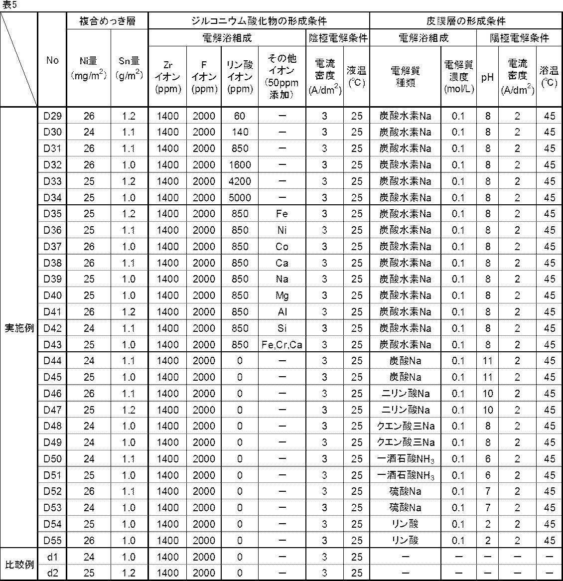
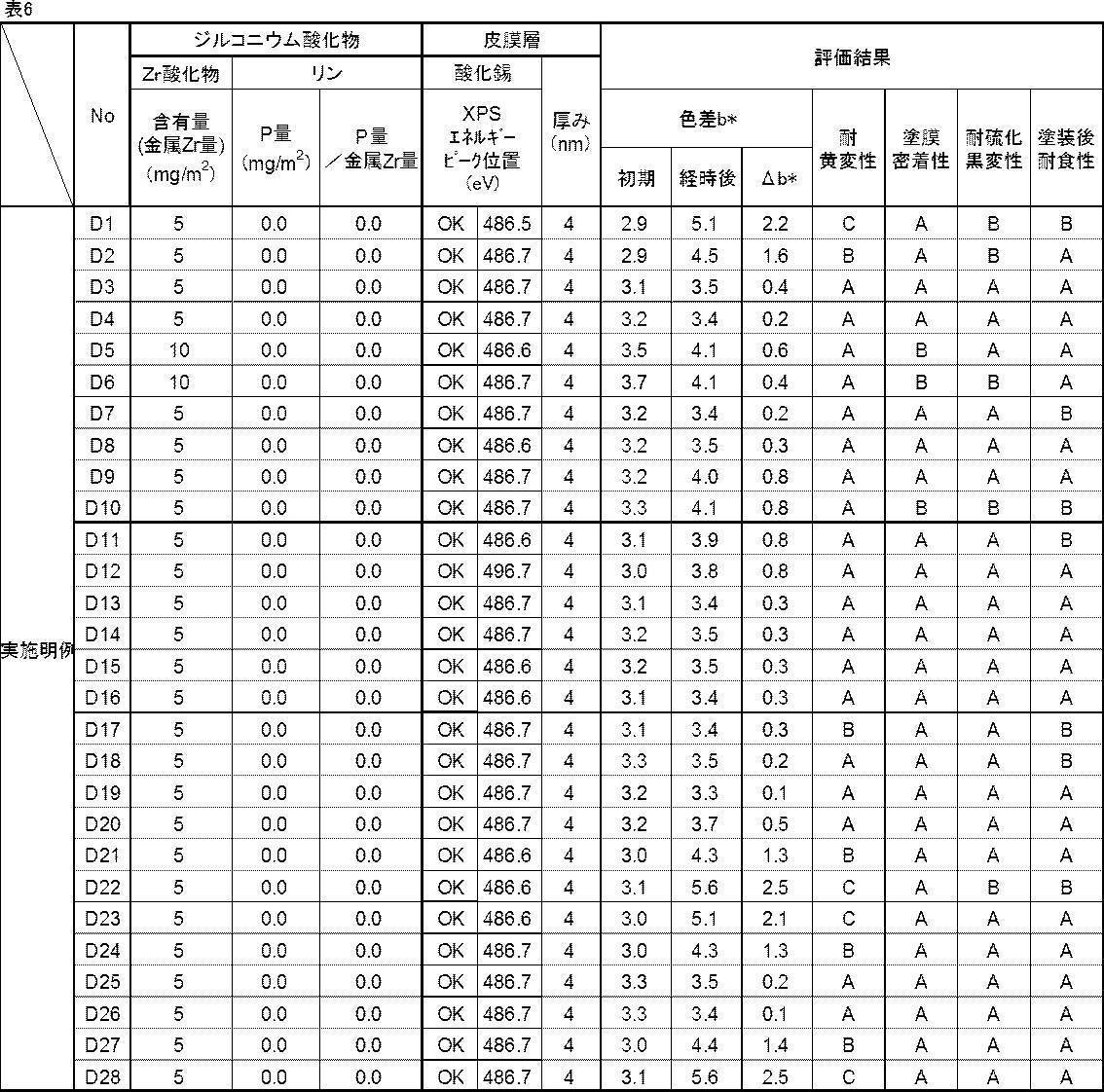
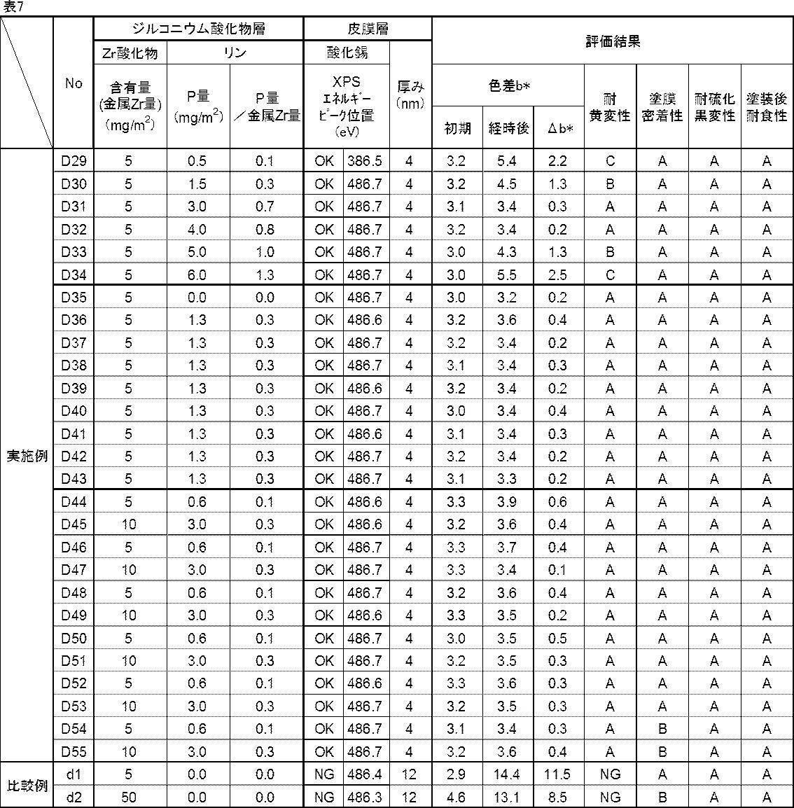
- Tables 4 to 7 show the results when the formation conditions of the zirconium oxide layer (cathodic electrolytic treatment conditions) and the coating layer formation conditions (anodic electrolytic treatment conditions) are variously changed.
- the following test materials were also prepared. Comparative examples d1 to d2: test materials in which a composite plating layer is formed on both surfaces of a steel sheet, a zirconium oxide layer is formed, and the zirconium oxide layer is not subjected to an anodic electrolytic treatment.
- the characteristics of the zirconium oxide layer in d1 to d2 (example in which the anodic electrolytic treatment is not applied to the zirconium oxide layer) are described in the column “Coating layer”.
- the Sn-based alloy-plated steel sheet of the present disclosure does not require conventional chromate treatment, and is excellent in yellowing resistance, coating film adhesion, and sulfurization blackening resistance, and therefore can be used as an environmentally friendly can material. It can be widely used for food cans, beverage cans, etc., and has very high industrial utility value.
Landscapes
- Chemical & Material Sciences (AREA)
- Engineering & Computer Science (AREA)
- Chemical Kinetics & Catalysis (AREA)
- Electrochemistry (AREA)
- Materials Engineering (AREA)
- Metallurgy (AREA)
- Organic Chemistry (AREA)
- Inorganic Chemistry (AREA)
- Other Surface Treatments For Metallic Materials (AREA)
- Electroplating Methods And Accessories (AREA)
Abstract
Description
以下の特許文献2では、リン酸アルミニウムを含む溶液を用いた処理によって、Al及びPと、Ni、Co及びCuの少なくとも1種と、シランカップリング剤との反応物を含む皮膜を形成させたSn系合金めっき鋼板が提案されている。
以下の特許文献3では、Snめっき層上にZnめっきをした後にZn単独めっき層が消失するまで加熱処理を施す、クロメート皮膜を有さないSnめっき鋼板の製造方法が提案されている。
以下の特許文献4及び特許文献5では、ジルコニウム、リン酸、フェノール樹脂等を含む化成処理皮膜を有するSn系合金めっき鋼板(容器用鋼板)が提案されている。
以下の特許文献6では、Snめっき層と、Snめっき層形成後に、リン酸塩水溶液中で、陰極電解処理、次いで陽極電解処理を施して形成された、酸化錫とリン酸錫とを含む化成処理層を有するSnめっき鋼板又はSn系合金めっき鋼板(容器用鋼板)が提案されている。
以下の特許文献7では、スズ酸化物、並びに、Zr、Ti及びPを含有する被膜を有するSnめっき鋼板又はSn系合金めっき鋼板(容器用鋼板)が提案されている。特許文献6では、被膜を形成するとき、陰極電解処理と陽極電解処理とを交互に行う交番電解を実施してもよいことが提案されている。
以下の特許文献8では、ZrおよびSiを有するSnめっき鋼板又はSn系合金めっき鋼板(容器用鋼板)が提案されている。特許文献8では、被膜を形成するとき、陰極電解処理と陽極電解処理とを交互に行う交番電解を実施してもよいことが提案されている。
特許文献2:特開2011-174172号公報
特許文献3:特開昭63-290292号公報
特許文献4:特開2007-284789号公報
特許文献5:特開2010-13728号公報
特許文献6:特開2009-249691号公報
特許文献7:国際公開第2015/001598号
特許文献8:特開2014-88587号公報
前記鋼板の少なくとも片面に形成され、Fe-Ni-Sn合金層と、前記Fe-Ni-Sn合金層上に位置する島状Sn層と、を有する複合めっき層と、
前記複合めっき層の表面に形成され、ジルコニウム酸化物と酸化錫とを含有する皮膜層と、
を有し、
前記複合めっき層が、質量%で、金属Ni換算量として2mg/m2以上200mg/m2以下のNiと、金属Sn換算量として0.1g/m2以上10g/m2以下のSnと、を含有し、
前記皮膜層中における前記ジルコニウム酸化物の含有量が、金属Zr量で0.2mg/m2以上50mg/m2以下であり、
前記皮膜層中における前記酸化錫のX線光電子分光法によるSn3d5/2の結合エネルギーのピーク位置が、金属Snの結合エネルギーのピーク位置よりも1.6eV以上大きい、Sn系合金めっき鋼板。
(2)前記皮膜層の厚みが、2nm以上100nm以下である、(1)に記載のSn系合金めっき鋼板。
(3)前記皮膜層は、単位面積当たりの質量比で、P量/金属Zr量が0.2以上1以下となるリンを更に含有する、(1)又は(2)に記載のSn系合金めっき鋼板。
本明細書において、「~」を用いて表される数値範囲は、「~」の前後に記載される数値を下限値及び上限値として含む範囲を意味する。
本明細書において、「工程」との用語は、独立した工程だけではなく、他の工程と明確に区別できない場合であってもその工程の所期の目的が達成されるのであれば、本用語に含まれる。
本明細書において、「鋼板」との用語は、複合めっき層及び皮膜層を形成する対象の母鋼板(いわゆるめっき原板)を意味する。
皮膜層中におけるジルコニウム酸化物の含有量は、金属Zr量で0.2mg/m2以上50mg/m2以下である。
皮膜層中における酸化錫のX線光電子分光法によるSn3d5/2の結合エネルギーのピーク位置は、金属Snの結合エネルギーのピーク位置よりも1.6eV以上大きい。
鋼板は、特に規定されるものではなく、一般的なSn系合金めっき鋼板に用いられている鋼板であれば、任意のものを使用可能である。鋼板は、例えば、低炭素鋼、極低炭素鋼などが挙げられる。また、用いる鋼板の製造方法及び材質も特に規定されるものではなく、例えば、鋳造から熱間圧延、酸洗、冷間圧延、焼鈍、調質圧延等の工程を経て製造された鋼板を挙げることができる。
鋼板の少なくとも片面には、複合めっき層(以下、単に「複合めっき層」とも称する)が形成される。この複合めっき層は、金属Ni換算量として片面当たり2mg/m2以上200mg/m2以下のNiと、金属Sn換算量として片面当たり0.1g/m2以上10g/m2以下のSnと、を含むFe-Ni-Sn合金層と、Fe-Ni-Sn合金層上に位置する島状のSnと、から構成されている。
なお、Fe-Ni-Sn合金層は、溶融加熱処理にて一部又は全部のNiと一部のSnとが合金化することで形成される。
Fe-Ni-Sn合金層は、耐食性を向上させる効果がある。これは、電気化学的に鉄よりも貴な金属であるNiとSnとがFeとの合金層を形成することで、Fe自体の耐食性も向上させることによる。
Niの量が、金属Ni換算量として片面当たり2mg/m2以上であれば、耐食性の効果が発現する。Niの量が多いほど耐食性向上の効果は増加する。一方、Niの量が、金属Ni換算量として片面当たり200mg/m2超過となると耐食性向上の効果は飽和し、それ以上に増やしても経済的に好ましくない。また、耐硫化黒変性に劣る。このため、Niの量は、金属Ni換算量として片面当たり2mg/m2以上200mg/m2以下とする。Niの量は、より好ましくは、金属Ni換算量として片面当たり2mg/m2以上180mg/m2以下である。
Fe-Ni-Sn合金層上に形成される島状のSn層は、耐食性と塗膜密着性とを向上させる効果がある。Snは、大気腐食環境下では鉄よりも貴な金属であり、バリア型皮膜としてFeの腐食を防ぐ。一方で、Snは、酸性飲料缶のような酸性腐食環境下では、鉄を犠牲防食して、耐食性を向上させる。また、島状にSn層が存在することで、アンカー効果、及び、海部に相当するFe-Ni-Sn合金層の存在による酸化錫の成長抑制効果によって、塗膜密着性を向上させる。また、酸化錫の成長が抑制されることで、黄変も抑制する効果がある。
なお、島状Sn層とは、複合めっき層を厚み方向から観察したとき、Fe-Ni-Sn合金層の表面を海部(つまり連続相)とし、Sn層を島部(分散相)として、複数のSn層の島部が海部に点在した状態で存在する層である。
Snの量が、金属Sn換算量として片面当たり0.1g/m2以上必要である。Snの量が増加するにつれて、耐食性と塗膜密着性向上の効果は増加する、一方で、Snの量が、金属Sn換算量として片面当たり10g/m2超過となると、耐食性向上の効果は飽和し、更なる増加は経済性の観点から好ましくない。また、塗膜密着性も低下する傾向にある。このため、Snの量は、金属Sn換算量として片面当たり0.1g/m2以上10g/m2以下とする。Snの量は、より好ましくは、金属Sn換算量として片面当たり0.2g/m2以上8g/m2以下である。
まず、複合めっき層上に皮膜層が形成されておらず、複合めっき層が露出している鋼板の試験片(複合めっき層のみが形成された鋼板の試験片)を準備する。その試験片を10%硝酸に浸漬して、Ni及びSnを含む複合めっき層を溶解し、得られた溶解液中のNi及びSnをICP発光分析法(例えば、アジレント・テクノロジー社製799ce、キャリアガスにArを使用。)で求める。そして、分析で得た強度信号と、濃度が既知の溶液から作成した検量線と、試験片の複合めっき層の形成面積とに基づいて、複合めっき層の付着量(Ni量、及びSn量)を求める。
まず、複合めっき層のNi量及びSn量が既知である基準試料を用い、スパッタリングを実施しながらGDSにより基準試料の複合めっき層中のNi及びSnの強度信号並びにスパッタ速度との関係をあらかじめ求め、検量線を作る。
一方、複合めっき層上に皮膜層が形成されている鋼板の試験片(複合めっき層及び皮膜層が順次形成された鋼板の試験片)を準備する。その試験片の皮膜層の表面から、スパッタをしながらGDSによる分析を実施し、複合めっき層のNi及びSnの強度信号を測定する。得られたNi及びSnの強度信号、スパッタ速度、並びに作成した検量線により、複合めっき層のNi量及びSn量を求める。
ここで、複合めっき層は、Zrの強度信号が、Zrの強度信号の最大値の1/2になる深さから、Feの強度信号が、Feの強度信号の最大値の1/2になる深さまでの領域と定義する。そして、当該領域のNi量及びSn量の平均値を、複合めっき層のNi量及びSn量とする。
このFe-Ni-Sn合金層上に、島状のSn層が形成された複合めっき層は、例えば、次の通り形成する。まず、鋼板の少なくとも片面に下地となるNiめっき層又はFe-Niめっき層を形成する。次に、このNiめっき層又はFe-Niめっき層の上にSnめっき層を形成する。そして、Niめっき層又はFe-Niめっき層とSnめっき層とを加熱溶融処理することで、複合めっき層が形成される。つまり、溶融加熱処理によって、鋼板のFeと、Niめっき層又はFe-Niめっき層のNiと、Snめっき層の一部のSnと、が合金化して、Fe-Ni-Sn合金層が形成されるとともに、残部のSnめっき層が島状Sn層となる。
本開示のSn系合金めっき鋼板は、鋼板の表面に形成された複合めっき層の表面に、ジルコニウム酸化物及び酸化錫の両者を含有する皮膜層を有する。
皮膜層中におけるジルコニウム酸化物の含有量は、金属Zr量(つまり金属Zr換算量)で片面当たり0.2mg/m2以上50mg/m2以下である。皮膜層中におけるジルコニウム酸化物の含有量は、片面当たりのジルコニウム酸化物の含有量である。
皮膜層中における酸化錫は、XPSによるSn3d5/2の結合エネルギーのピーク位置が、金属Snの結合エネルギーのピーク位置よりも1.6eV以上大きい酸化錫である。
つまり、酸化錫のXPSによるSn3d5/2の結合エネルギーのピーク位置は、金属Snの結合エネルギーのピーク位置よりも1.6eV以上2.0eV以下の範囲で大きいことがよい。
ここで、後述する測定方法により「酸化錫のXPSによるSn3d5/2の結合エネルギーのピーク位置が、金属Snの結合エネルギーのピーク位置よりも1.6eV以上大きいピーク位置」が測定されれば、皮膜層には、安定型酸化錫以外の、その他の構造の酸化錫(例えば、XPSによるSn3d5/2の結合エネルギーのピーク位置が金属Snの結合エネルギーのピーク位置よりも1.6eV未満である酸素欠乏型酸化錫など)が含まれていても問題ない。
図1に示すように、本開示のSn系複合めっき鋼板は、複合めっき層の表面に、ジルコニウム酸化物と酸化錫とが共存した皮膜層が存在していることがわかる。
皮膜層の厚みは、XPS深さ方向分析において、錫酸化物として存在するSn、金属錫として存在するSn、ジルコニウム酸化物として存在するZr、の元素濃度の合計を100%としたときに、表面から、金属錫(金属錫として存在するSn)の元素濃度が10%以下の領域までの厚みであって、SiO2換算厚みで求められる値である。
皮膜層を形成するためには、まず、複合めっき層が形成された鋼板の複合めっき層の表面に対して、ジルコニウム酸化物を含有するジルコニウム酸化物層を形成する。
従って、ジルコニウム酸化物を含有するジルコニウム酸化物層の形成には、陰極電解処理による方法を利用することが好ましい。
電解質の濃度の下限は、特に規定するものではなく、電気伝導度として0.1S/m以上を満たす濃度とすることが好ましい。これらの電解質の濃度の上限も特に規定はしないが、電解質の濃度が大き過ぎる場合は保管時に沈殿し、配管詰まり等の障害を引き起こす可能性があるため、各電解質の0℃における溶解度以下とすることが好ましい。電解質の濃度は、好ましくは、電気伝導度で0.5S/m以上4S/m以下を満たす濃度であり、より好ましくは、電気伝導度で1S/m以上2.5S/m以下を満たす濃度である。
なお、電気伝導度は、市販の電気伝導度計を用いて測定すればよく、例えば、東亜ディーケーケー株式会社製の電気伝導率セルCT-27112B等を用いることが可能である。
試験材の作製方法について説明する。なお、後述する各例の試験材は、この試験材の作製方法に準じて作製した。
まず、板厚0.2mmの低炭素冷延鋼板に対し、前処理として、電解アルカリ脱脂、水洗、希硫酸浸漬酸洗、水洗した後、硫酸浴にてNiめっきをした。Niめっき層の付着量は、金属Ni換算量で片面当たり1mg/m2以上300mg/m2以下の範囲とした。更に、Niめっき層の上に、フェノールスルホン酸浴を用いて、電気Snめっきを施した。Snめっき層の付着量は、金属Sn換算量で片面当たり0.08g/m2以上15g/m2以下の範囲とした。これら処理を経て作製したNiめっき層及びSnめっき層が両面に形成された鋼板を加熱溶融処理して、Fe-Ni-Sn合金層とFe-Ni-Sn合金層上に位置する島状Sn層とを有する複合めっき層が両面に形成された鋼板を作製した。
複合めっき層の付着量(Ni量、及びSn量)は、既述の「ICP発光分析法による測定方法」により測定した。
皮膜層のジルコニウム酸化物の含有量(金属Zr量)及びP量を、次の通り測定した。
金属Zr量及びP量の含有量が既知である複数の皮膜層付き鋼板の試験片を準備した。次に、各試験片について、蛍光X線分析装置(リガク社製ZSX Primus)により、試験片の皮膜層の表面から、金属Zr及びPに由来する蛍光X線の強度を事前に測定した。そして、測定した蛍光X線の強度と金属Zr及びPとの関係を示した検量線を、各々準備した。
その上で、測定対象となるSn系複合めっき鋼板の試験片を準備した。この試験片の皮膜層の表面を蛍光X線分析装置(リガク社製ZSX Primus)により、金属Sn、金属Zr及びPに由来する蛍光X線の強度を測定した。得られた蛍光X線強度と予め準備した金属Zr及びPに関する検量線とを利用することで、皮膜層のジルコニウム酸化物の含有量(金属Zr量)及びP量を算出した。
なお、測定条件は、X線源Rh、管電圧50kV、管電流60mA、分光結晶LiF1、測定径30mmとした。
皮膜層の表面に対して、XPS(ULVAC-PHI製PHI Quantera SXM)による測定を実施し、皮膜層中における酸化錫のSn3d5/2の結合エネルギーのピーク位置(表中「XPSエネルギーピーク位置」と表記)を調べた。
なお、測定条件は、X線源mono-AlKα線(hν=1466.6eV、100.8W)、X線径100μmφ、検出深さ数nm(取出し角45°)、分析範囲1400×100μmとした。
そして、酸化錫のSn3d5/2の結合エネルギーのピーク位置が金属Snの結合エネルギーのピーク位置(=484.9eV)よりも1.6eV以上大きければ、安定型酸化錫が主として形成されているとして「OK」と評価した。1.6eV未満であれば、酸素欠乏型酸化錫が主として形成されているとして「NG」と評価した。評価「OK」を合格とした。
皮膜層の厚みは、XPS(ULVAC-PHI製PHI Quantera SXM)により測定した。具体的には、測定対象となるSn系合金めっき鋼板の試験片を準備する。この試験片の皮膜層の表面から、XPS(ULVAC-PHI製PHI Quantera SXM)による厚み方向(深さ方向)の分析を実施し、酸化錫として存在するSn、金属錫として存在するSn、ジルコニウム酸化物として存在するZr、の元素濃度の合計を100%としたときに、表面から、金属錫(金属錫として存在するSn)の元素濃度が10%以下の領域までの厚みをSiO2換算厚みで算出した。
なお、測定条件は、X線源mono-AlKα線(hν=1466.6eV、100.8W)、X線径100μmφ、検出深さ数nm(取出し角45°)、分析範囲1400×100μm、中和銃1.0V,20μA、スパッタ条件Ar+、加速電圧1kV、スパッタ速度1.5nm/min(SiO2換算値)とした。
Sn系合金めっき鋼板の試験材を、40℃、相対湿度80%に保持した恒温恒湿槽中に4週間載置する湿潤試験を行い、湿潤試験前後における色差b*値の変化量△b*を求めて、評価した。△b*が1以下であれば「A」とし、1超過2以下であれば「B」とし、2超過3以下であれば「C」とし、3を超過していれば「NG」とした。評価「A」、「B」、及び「C」を合格とした。b*は、市販の色差計であるスガ試験機製SC-GV5を用いて測定した。b*の測定条件は、光源C、全反射、測定径30mmである。
塗膜密着性は、以下のようにして評価した。
Sn系合金めっき鋼板の試験材を、[耐黄変性]に記載の方法で湿潤試験した後、表面に、市販の缶用エポキシ樹脂塗料を乾燥質量で7g/m2塗布し、200℃で10分焼き付け、24時間室温に置いた。その後、得られたSn系複合めっき鋼板に対し、鋼板表面に達する傷を碁盤目状に入れ(3mm間隔で縦横7本ずつの傷)、その部位のテープ剥離試験をすることで評価した。テープ貼り付け部位の塗膜が全て剥離していなければ「A」とし、碁盤目の傷部周囲で塗膜剥離が認められれば「B」とし、碁盤目の枡内に塗膜剥離が認められれば「NG」とした。評価「A」、及び「B」を合格とした。
耐硫化黒変性は、以下のようにして評価した。
上記[塗膜密着性]に記載の方法で作製及び湿潤試験したSn系合金めっき鋼板の試験材の表面に、市販の缶用エポキシ樹脂塗料を乾燥質量で7g/m2塗布した後、200℃で10分焼き付け、24時間室温に置いた。その後、得られたSn系複合めっき鋼板を所定のサイズに切断し、リン酸二水素ナトリウムを0.3%、リン酸水素ナトリウムを0.7%、L-システイン塩酸塩を0.6%からなる水溶液中に浸漬し、密封容器中で121℃・60分のレトルト処理を行い、試験後の外観から評価した。試験前後で外観の変化が全く認められなければ「A」とし、僅かに(10%以下)黒変が認められれば「B」とし、試験面の10%超過の領域に黒変が認められれば「NG」とした。評価「A」及び「B」を合格とした。
塗装後耐食性は、以下のようにして評価した。
上記[塗膜密着性]に記載の方法で作製及び湿潤試験したSn系合金めっき鋼板の試験材の表面に、市販の缶用エポキシ樹脂塗料を乾燥質量で7g/m2塗布した後、200℃で10分焼き付け、24時間室温に置いた。その後、得られたSn系複合めっき鋼板を所定のサイズに切断し、市販のトマトジュースに60℃で7日間浸漬した後の錆の発生有無を、目視にて評価した。錆が全く認められなければ「A」とし、試験面全体の10%以下の面積率で錆が認められれば「B」とし、試験面全体の10%超えの面積率で錆が認められれば「NG」とした。評価「A」及び「B」を合格とした。
表1は、複合めっき層中のNi量及びSn量と皮膜層中のジルコニウム酸化物の含有量とを変化させた場合の結果である。フッ化ジルコニウムを含む溶液中のジルコニウム濃度は、1400ppmとした。ジルコニウム酸化物層を形成した後は、ジルコニウム酸化物層に対して、電気伝導度2.0S/mの炭酸水素ナトリウム溶液(液性:弱酸性~アルカリ性、pH=8)中で陽極電解処理し、皮膜層を形成させた。陽極電解液の液温は25℃とし、陽極電解処理の通電量は2C/dm2とした。
比較例であるa1~a2:鋼板の両面に複合めっき層を形成後、ジルコニウム酸化物層を形成させ、ジルコニウム酸化物層に陽極電解処理をしない試験材
比較例であるa9:鋼板の両面に複合めっき層を形成後、ジルコニウム酸化物層の形成前に、電気伝導度2.0S/m、液温25℃の炭酸水素ナトリウム溶液(陽極電解液)中で、電流密度2A/dm2の条件で陽極電解処理を実施し、その後、ジルコニウム酸化物層を形成させ、ジルコニウム酸化物層に陽極電解処理をしない試験材
比較例であるa10:鋼板の両面に複合めっき層を形成後、液温35℃、pH4のフッ化ジルコニウムを含む水溶液中で、電流密度3A/dm2の条件で、陰極電解処理と陽極電解処理とを交互に行う交番電解処理でジルコニウム酸化物層を形成させ、ジルコニウム酸化物層に陽極電解処理をしない試験材
比較例であるa11:鋼板の両面に複合めっき層を形成後、鋼板の複合めっき層に、電気伝導度2.0S/m、液温25℃の炭酸水素ナトリウム溶液(陽極電解液)中で、電流密度2A/dm2の陽極電解処理を実施し、その後、ジルコニウム酸化物層を形成しない試験材
なお、表1中、比較例であるa1~a2、a9、a10(ジルコニウム酸化物層に陽極電解処理を施していない例)におけるジルコニウム酸化物層の特性は、「皮膜層」の欄に記載する。
また、比較例であるa11における錫酸化物層の特性は、「皮膜層」の欄に記載する。

特に、比較例であるa9のように、鋼板の両面に複合めっき層の形成後、ジルコニウム酸化物層の形成前に、陽極電解処理を実施しても、その後形成されるジルコニウム酸化物層には、安定型酸化錫が主として形成されていないことがわかる。
比較例であるa10のように、陰極電解処理と陽極電解処理とを交互に行う交番電解処理でジルコニウム酸化物層を形成しても、ジルコニウム酸化物層には、安定型酸化錫が主として形成されていないことがわかる。
比較例であるa11のように、ジルコニウム酸化物層を形成せず、鋼板の複合めっき層に陽極電解処理を実施すると、皮膜層として酸化錫層が形成される。しかし、この酸化錫層は、安定型酸化錫層ではないことがわかる。
表2は、皮膜層の厚みを変化させた場合の結果である。皮膜層の厚みは、陽極電解処理の通電量を変えることで変化させた。

表3は、皮膜層中にリンが含まれる場合の結果である。これらの試験材は、リン酸イオン60ppm~5000ppm添加させた1400ppmのジルコニウムイオンを含む陰極電解処理液中で、複合めっき層が形成された鋼板を陰極電解処理することで作製した。
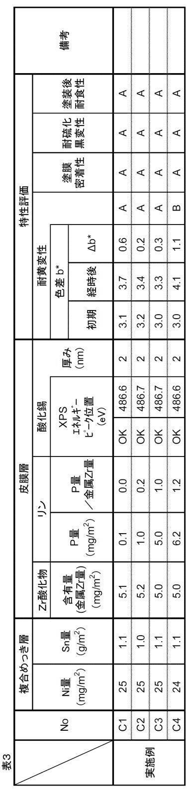
表4~表7は、ジルコニウム酸化物層の形成条件(陰極電解処理条件)と皮膜層の形成条件(陽極電解処理条件)とを種々変更した場合の結果である。
なお、比較として、次の試験材もあわせて作製した。
比較例であるd1~d2:鋼板の両面に複合めっき層を形成後、ジルコニウム酸化物層を形成させ、ジルコニウム酸化物層に陽極電解処理をしない試験材
なお、表4~表7中、比較例であるd1~d2(ジルコニウム酸化物層に陽極電解処理を施していない例)におけるジルコニウム酸化物層の特性は、「皮膜層」の欄に記載する。

本明細書に記載された全ての文献、特許出願、および技術規格は、個々の文献、特許出願、および技術規格が参照により取り込まれることが具体的かつ個々に記された場合と同程度に、本明細書中に参照により取り込まれる。
Claims (3)
- 鋼板と、
前記鋼板の少なくとも片面に形成され、Fe-Ni-Sn合金層と、前記Fe-Ni-Sn合金層上に位置する島状Sn層と、を有する複合めっき層と、
前記複合めっき層の表面に形成され、ジルコニウム酸化物と酸化錫とを含有する皮膜層と、
を有し、
前記複合めっき層が、質量%で、金属Ni換算量として2mg/m2以上200mg/m2以下のNiと、金属Sn換算量として0.1g/m2以上10g/m2以下のSnと、を含有し、
前記皮膜層中における前記ジルコニウム酸化物の含有量が、金属Zr量で0.2mg/m2以上50mg/m2以下であり、
前記皮膜層中における前記酸化錫のX線光電子分光法によるSn3d5/2の結合エネルギーのピーク位置が、金属Snの結合エネルギーのピーク位置よりも1.6eV以上大きい、Sn系合金めっき鋼板。 - 前記皮膜層の厚みが、2nm以上100nm以下である、請求項1に記載のSn系合金めっき鋼板。
- 前記皮膜層は、単位面積当たりの質量比で、P量/金属Zr量が0.2以上1以下となるリンを更に含有する、請求項1又は2に記載のSn系合金めっき鋼板。
Priority Applications (5)
| Application Number | Priority Date | Filing Date | Title |
|---|---|---|---|
| JP2018519587A JP6806152B2 (ja) | 2016-05-24 | 2017-05-24 | Sn系合金めっき鋼板 |
| CN201780030385.8A CN109154098B (zh) | 2016-05-24 | 2017-05-24 | Sn系合金镀覆钢板 |
| KR1020187032075A KR102164120B1 (ko) | 2016-05-24 | 2017-05-24 | Sn계 합금 도금 강판 |
| EP17802852.8A EP3467155A4 (en) | 2016-05-24 | 2017-05-24 | Sn alloy-plated steel sheet |
| US16/302,903 US10865491B2 (en) | 2016-05-24 | 2017-05-24 | Sn-based alloy plated steel sheet |
Applications Claiming Priority (2)
| Application Number | Priority Date | Filing Date | Title |
|---|---|---|---|
| JP2016103381 | 2016-05-24 | ||
| JP2016-103381 | 2016-05-24 |
Publications (1)
| Publication Number | Publication Date |
|---|---|
| WO2017204266A1 true WO2017204266A1 (ja) | 2017-11-30 |
Family
ID=60411822
Family Applications (1)
| Application Number | Title | Priority Date | Filing Date |
|---|---|---|---|
| PCT/JP2017/019436 Ceased WO2017204266A1 (ja) | 2016-05-24 | 2017-05-24 | Sn系合金めっき鋼板 |
Country Status (7)
| Country | Link |
|---|---|
| US (1) | US10865491B2 (ja) |
| EP (1) | EP3467155A4 (ja) |
| JP (1) | JP6806152B2 (ja) |
| KR (1) | KR102164120B1 (ja) |
| CN (1) | CN109154098B (ja) |
| TW (1) | TWI633210B (ja) |
| WO (1) | WO2017204266A1 (ja) |
Cited By (3)
| Publication number | Priority date | Publication date | Assignee | Title |
|---|---|---|---|---|
| JP6642774B1 (ja) * | 2018-03-01 | 2020-02-12 | 日本製鉄株式会社 | Snめっき鋼板及びSnめっき鋼板の製造方法 |
| JP2020027130A (ja) * | 2018-08-09 | 2020-02-20 | キヤノン株式会社 | 回折光学素子およびそれを用いた光学機器 |
| JP2021123744A (ja) * | 2020-02-04 | 2021-08-30 | 日本製鉄株式会社 | Sn系めっき鋼板 |
Families Citing this family (2)
| Publication number | Priority date | Publication date | Assignee | Title |
|---|---|---|---|---|
| JP6870731B2 (ja) * | 2017-04-13 | 2021-05-12 | 日本製鉄株式会社 | Snめっき鋼板及びSnめっき鋼板の製造方法 |
| PH12022552425A1 (en) | 2020-03-26 | 2024-01-03 | Nippon Steel Corp | Sn-BASED PLATED STEEL SHEET |
Citations (2)
| Publication number | Priority date | Publication date | Assignee | Title |
|---|---|---|---|---|
| WO2008123632A1 (ja) * | 2007-04-04 | 2008-10-16 | Nippon Steel Corporation | 缶用めっき鋼板及びその製造方法 |
| WO2015001598A1 (ja) * | 2013-07-01 | 2015-01-08 | Jfeスチール株式会社 | 容器用鋼板 |
Family Cites Families (16)
| Publication number | Priority date | Publication date | Assignee | Title |
|---|---|---|---|---|
| GB2157319A (en) * | 1984-04-13 | 1985-10-23 | Toyo Kohan Co Ltd | Tin free steel and its production |
| JPS63290292A (ja) | 1987-05-20 | 1988-11-28 | Nippon Steel Corp | 耐錆性、溶接性に優れた薄Snメツキ鋼板の製造方法 |
| JP4379005B2 (ja) | 2002-06-05 | 2009-12-09 | Jfeスチール株式会社 | Si含有化成皮膜を有する錫系めっき鋼板の製造方法 |
| WO2003104528A1 (ja) * | 2002-06-05 | 2003-12-18 | Jfeスチール株式会社 | 錫めっき鋼板及びその製造方法 |
| JP5093797B2 (ja) * | 2006-03-24 | 2012-12-12 | 新日本製鐵株式会社 | 製缶加工性に優れた容器用鋼板 |
| EP2180084B1 (en) * | 2007-08-23 | 2018-10-10 | Nippon Steel & Sumitomo Metal Corporation | Environmentally friendly steel sheet for container material, process for producing the same, and environmentally friendly laminated steel sheet for container material and precoated steel sheet for container material each produced from that steel sheet |
| JP5304000B2 (ja) | 2008-04-07 | 2013-10-02 | 新日鐵住金株式会社 | 溶接性、外観、製缶加工密着性に優れた容器用鋼板 |
| JP4920627B2 (ja) * | 2008-04-16 | 2012-04-18 | 新日本製鐵株式会社 | 缶用めっき鋼板及びその製造方法 |
| JP4886811B2 (ja) | 2008-06-05 | 2012-02-29 | 新日本製鐵株式会社 | 有機皮膜性能に優れた容器用鋼板およびその製造方法 |
| JP4660626B2 (ja) | 2009-02-04 | 2011-03-30 | 新日本製鐵株式会社 | レトルト後塗膜密着性に優れたスズめっき鋼板及びその製造方法 |
| JP2011174172A (ja) | 2010-01-28 | 2011-09-08 | Jfe Steel Corp | 錫めっき鋼板およびその製造方法 |
| KR101430216B1 (ko) * | 2010-04-06 | 2014-08-18 | 신닛테츠스미킨 카부시키카이샤 | 환경에 대한 부하가 적은 용기 재료용 강판의 제조 방법과 환경에 대한 부하가 적은 용기 재료용 강판 및 이것을 사용한 용기 재료용 라미네이트 강판 및 용기 재료용 도장 프리코트 강판 |
| TWI449813B (zh) * | 2010-06-29 | 2014-08-21 | Nippon Steel & Sumitomo Metal Corp | 容器用鋼板及其製造方法 |
| JP5978923B2 (ja) | 2012-10-29 | 2016-08-24 | Jfeスチール株式会社 | 容器用鋼板、その製造に用いられる処理液、および、容器用鋼板の製造方法 |
| US10443141B2 (en) * | 2013-05-21 | 2019-10-15 | Nippon Steel Corporation | Steel sheet for containers, and method for producing steel sheet for containers |
| JP2015045047A (ja) * | 2013-08-27 | 2015-03-12 | Jx日鉱日石金属株式会社 | 電子部品用金属材料及びその製造方法、それを用いたコネクタ端子、コネクタ及び電子部品 |
-
2017
- 2017-05-24 CN CN201780030385.8A patent/CN109154098B/zh active Active
- 2017-05-24 WO PCT/JP2017/019436 patent/WO2017204266A1/ja not_active Ceased
- 2017-05-24 TW TW106117265A patent/TWI633210B/zh active
- 2017-05-24 KR KR1020187032075A patent/KR102164120B1/ko active Active
- 2017-05-24 EP EP17802852.8A patent/EP3467155A4/en not_active Withdrawn
- 2017-05-24 US US16/302,903 patent/US10865491B2/en active Active
- 2017-05-24 JP JP2018519587A patent/JP6806152B2/ja active Active
Patent Citations (2)
| Publication number | Priority date | Publication date | Assignee | Title |
|---|---|---|---|---|
| WO2008123632A1 (ja) * | 2007-04-04 | 2008-10-16 | Nippon Steel Corporation | 缶用めっき鋼板及びその製造方法 |
| WO2015001598A1 (ja) * | 2013-07-01 | 2015-01-08 | Jfeスチール株式会社 | 容器用鋼板 |
Non-Patent Citations (2)
| Title |
|---|
| KEIJI ARIGA ET AL.: "X-sen Kodenshi Bunkoho no Hyomen Shori eno Oyo", THE JOURNAL OF THE METAL FINISHING SOCIETY, vol. 27, no. 1, 1976, pages 7 - 14, XP055583955 * |
| See also references of EP3467155A4 * |
Cited By (7)
| Publication number | Priority date | Publication date | Assignee | Title |
|---|---|---|---|---|
| JP6642774B1 (ja) * | 2018-03-01 | 2020-02-12 | 日本製鉄株式会社 | Snめっき鋼板及びSnめっき鋼板の製造方法 |
| KR20200111772A (ko) * | 2018-03-01 | 2020-09-29 | 닛폰세이테츠 가부시키가이샤 | Sn 도금 강판 및 Sn 도금 강판의 제조 방법 |
| EP3760763A4 (en) * | 2018-03-01 | 2021-11-24 | Nippon Steel Corporation | SN-CLAD STEEL SHEET AND MANUFACTURING PROCESS FOR SN-CLAD STEEL SHEET |
| KR102364143B1 (ko) | 2018-03-01 | 2022-02-18 | 닛폰세이테츠 가부시키가이샤 | Sn 도금 강판 및 Sn 도금 강판의 제조 방법 |
| JP2020027130A (ja) * | 2018-08-09 | 2020-02-20 | キヤノン株式会社 | 回折光学素子およびそれを用いた光学機器 |
| JP2021123744A (ja) * | 2020-02-04 | 2021-08-30 | 日本製鉄株式会社 | Sn系めっき鋼板 |
| JP7410386B2 (ja) | 2020-02-04 | 2024-01-10 | 日本製鉄株式会社 | Sn系めっき鋼板 |
Also Published As
| Publication number | Publication date |
|---|---|
| KR20180132120A (ko) | 2018-12-11 |
| JP6806152B2 (ja) | 2021-01-06 |
| TWI633210B (zh) | 2018-08-21 |
| US10865491B2 (en) | 2020-12-15 |
| JPWO2017204266A1 (ja) | 2019-03-14 |
| CN109154098B (zh) | 2021-03-09 |
| KR102164120B1 (ko) | 2020-10-12 |
| CN109154098A (zh) | 2019-01-04 |
| EP3467155A4 (en) | 2019-10-30 |
| TW201812111A (zh) | 2018-04-01 |
| US20190292673A1 (en) | 2019-09-26 |
| EP3467155A1 (en) | 2019-04-10 |
Similar Documents
| Publication | Publication Date | Title |
|---|---|---|
| JP6855833B2 (ja) | Snめっき鋼板及びSnめっき鋼板の製造方法 | |
| JP6806151B2 (ja) | Snめっき鋼板 | |
| JP6870731B2 (ja) | Snめっき鋼板及びSnめっき鋼板の製造方法 | |
| JP6806152B2 (ja) | Sn系合金めっき鋼板 | |
| JP6642774B1 (ja) | Snめっき鋼板及びSnめっき鋼板の製造方法 | |
| JP7295486B2 (ja) | Sn系めっき鋼板 | |
| JP2018135570A (ja) | Sn系合金めっき鋼板及びSn系合金めっき鋼板の製造方法 | |
| JP7239020B2 (ja) | Sn系めっき鋼板 | |
| JP7410386B2 (ja) | Sn系めっき鋼板 | |
| TW202124788A (zh) | Sn系鍍敷鋼板 | |
| JP2015140468A (ja) | 容器用鋼板およびその製造方法 |
Legal Events
| Date | Code | Title | Description |
|---|---|---|---|
| ENP | Entry into the national phase |
Ref document number: 20187032075 Country of ref document: KR Kind code of ref document: A |
|
| ENP | Entry into the national phase |
Ref document number: 2018519587 Country of ref document: JP Kind code of ref document: A |
|
| NENP | Non-entry into the national phase |
Ref country code: DE |
|
| 121 | Ep: the epo has been informed by wipo that ep was designated in this application |
Ref document number: 17802852 Country of ref document: EP Kind code of ref document: A1 |
|
| ENP | Entry into the national phase |
Ref document number: 2017802852 Country of ref document: EP Effective date: 20190102 |