WO2017208503A1 - 地図データ更新装置、地図データ更新方法および地図データ更新プログラム - Google Patents
地図データ更新装置、地図データ更新方法および地図データ更新プログラム Download PDFInfo
- Publication number
- WO2017208503A1 WO2017208503A1 PCT/JP2017/004920 JP2017004920W WO2017208503A1 WO 2017208503 A1 WO2017208503 A1 WO 2017208503A1 JP 2017004920 W JP2017004920 W JP 2017004920W WO 2017208503 A1 WO2017208503 A1 WO 2017208503A1
- Authority
- WO
- WIPO (PCT)
- Prior art keywords
- map data
- measurement
- feature
- data
- map
- Prior art date
- Legal status (The legal status is an assumption and is not a legal conclusion. Google has not performed a legal analysis and makes no representation as to the accuracy of the status listed.)
- Ceased
Links
Images









Classifications
-
- G—PHYSICS
- G01—MEASURING; TESTING
- G01C—MEASURING DISTANCES, LEVELS OR BEARINGS; SURVEYING; NAVIGATION; GYROSCOPIC INSTRUMENTS; PHOTOGRAMMETRY OR VIDEOGRAMMETRY
- G01C21/00—Navigation; Navigational instruments not provided for in groups G01C1/00 - G01C19/00
- G01C21/38—Electronic maps specially adapted for navigation; Updating thereof
- G01C21/3804—Creation or updating of map data
- G01C21/3859—Differential updating map data
-
- G—PHYSICS
- G09—EDUCATION; CRYPTOGRAPHY; DISPLAY; ADVERTISING; SEALS
- G09B—EDUCATIONAL OR DEMONSTRATION APPLIANCES; APPLIANCES FOR TEACHING, OR COMMUNICATING WITH, THE BLIND, DEAF OR MUTE; MODELS; PLANETARIA; GLOBES; MAPS; DIAGRAMS
- G09B29/00—Maps; Plans; Charts; Diagrams, e.g. route diagram
- G09B29/003—Maps
-
- G—PHYSICS
- G01—MEASURING; TESTING
- G01C—MEASURING DISTANCES, LEVELS OR BEARINGS; SURVEYING; NAVIGATION; GYROSCOPIC INSTRUMENTS; PHOTOGRAMMETRY OR VIDEOGRAMMETRY
- G01C21/00—Navigation; Navigational instruments not provided for in groups G01C1/00 - G01C19/00
- G01C21/26—Navigation; Navigational instruments not provided for in groups G01C1/00 - G01C19/00 specially adapted for navigation in a road network
- G01C21/28—Navigation; Navigational instruments not provided for in groups G01C1/00 - G01C19/00 specially adapted for navigation in a road network with correlation of data from several navigational instruments
-
- G—PHYSICS
- G06—COMPUTING OR CALCULATING; COUNTING
- G06T—IMAGE DATA PROCESSING OR GENERATION, IN GENERAL
- G06T11/00—Two-dimensional [2D] image generation
- G06T11/60—Creating or editing images; Combining images with text
- G06T11/65—Creating or editing images; Combining images with text on geographic maps
-
- G—PHYSICS
- G09—EDUCATION; CRYPTOGRAPHY; DISPLAY; ADVERTISING; SEALS
- G09B—EDUCATIONAL OR DEMONSTRATION APPLIANCES; APPLIANCES FOR TEACHING, OR COMMUNICATING WITH, THE BLIND, DEAF OR MUTE; MODELS; PLANETARIA; GLOBES; MAPS; DIAGRAMS
- G09B29/00—Maps; Plans; Charts; Diagrams, e.g. route diagram
Definitions
- the present invention relates to a technique for updating map data.
- the data measured by the MMS measurement vehicle contains measurement errors.
- the map data is created after correcting the measurement data.
- the measurement data obtained by MMS cannot be directly reflected in the map data, and the data measured by a surveying method to correct the measured data. Had to get.
- Patent Document 1 discloses a technique for creating map data using MMS.
- the object of the present invention is to make it possible to update map data using measurement data.
- the map data update device of the present invention is Map data including position information of features existing at the reference time, and data obtained by measurement performed at the measurement time after the reference time, including data including position information of the features existing at the measurement time Using a certain measurement data, a deviation amount calculation unit for calculating a deviation amount of the position of the feature common to the map data and the measurement data; Based on the calculated amount of deviation, a deviation correction unit that corrects position information included in the measurement data; Using the map data and the corrected measurement data, a difference extraction unit that extracts a difference between a set of features existing at the reference time and a set of features measured at the measurement time; A map data updating unit that updates the map data based on the extracted difference.
- FIG. 1 is a configuration diagram of a map data update device 100 according to Embodiment 1.
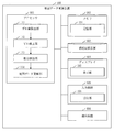
- FIG. 3 is a configuration diagram of a storage unit 191 in the first embodiment.
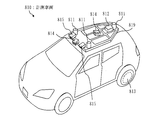
- FIG. 3 is a configuration diagram of a measurement vehicle 810 according to Embodiment 1.
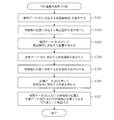
- 5 is a flowchart of a map data update method according to the first embodiment.
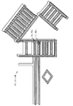
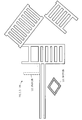
- FIG. 3 is a diagram showing a map image 201 and a white line 202 in the first embodiment.
- FIG. 3 shows a point cloud image 211 and a white line 212 in the first embodiment.
- FIG. 3 is a diagram in which white lines (202, 212) in Embodiment 1 are superimposed.
- FIG. 5 shows the center of gravity (203, 213) of a white line in the first embodiment.
- FIG. 7 is a flowchart of a deviation amount calculation process (S100) in the first embodiment.
- FIG. 5 shows a measurement point group 214 and a boundary line 215 according to the first embodiment. The figure which shows the new feature 221 and the extinction feature 222 in Embodiment 1.
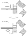
- FIG. 6 shows white lines 202 before and after updating in the first embodiment.
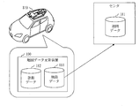
- FIG. 3 shows a usage pattern 1 in the first embodiment.
- FIG. 5 shows a usage pattern 2 in the first embodiment.
- FIG. 3 shows a summary in the first embodiment.
- FIG. 10 shows an overlapping portion of white lines (202, 212) in the second embodiment.
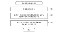
- 9 is a flowchart of a deviation amount calculation process (S100) in the second embodiment.
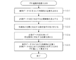
- FIG. 10 is a flowchart of a deviation amount calculation process (S100) in Example 1 of Embodiment 3.
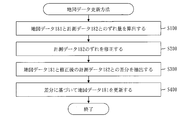
- FIG. 10 is a flowchart of a map data update method according to the fourth embodiment.
- Embodiment 1 FIG. The form which updates map data is demonstrated based on FIGS. 1-15. *** Explanation of configuration *** Based on FIG. 1, the structure of the map data update apparatus 100 is demonstrated.
- the map data update device 100 is a computer including hardware such as a processor 901, a memory 902, an auxiliary storage device 903, a display 904, an input device 905, and a communication device 906. These hardwares are connected to each other via signal lines.
- the processor 901 is an IC (Integrated Circuit) that performs processing, and controls other hardware.
- the processor 901 is a CPU, DSP, or GPU.
- CPU is an abbreviation for Central Processing Unit
- DSP is an abbreviation for Digital Signal Processor
- GPU is an abbreviation for Graphics Processing Unit.
- the memory 902 is a volatile storage device.
- the memory 902 is also called main memory or main memory.
- the memory 902 is a RAM (Random Access Memory).
- the auxiliary storage device 903 is a nonvolatile storage device. Specifically, the auxiliary storage device 903 is a ROM, HDD, or flash memory. ROM is an abbreviation for Read Only Memory, and HDD is an abbreviation for Hard Disk Drive.
- processor 901, the memory 902, and the auxiliary storage device 903 are combined is referred to as a “processing circuit”.
- the display 904 is a display device that displays an image or the like. Specifically, the display 904 is a liquid crystal display. The display 904 is also called a monitor.
- the input device 905 is a device that accepts input. Specifically, the input device 905 is a keyboard, a mouse, a numeric keypad, or a touch panel.
- the communication device 906 is a device that performs communication, and includes a receiver and a transmitter. Specifically, the communication device 906 is a communication chip or a NIC (Network Interface Card).
- NIC Network Interface Card
- the map data update device 100 includes “parts” such as a deviation amount calculation unit 111, a deviation correction unit 112, a difference extraction unit 113, and a map data update unit 114 as elements of a functional configuration.
- the function of “part” is realized by software. The function of “part” will be described later.
- the auxiliary storage device 903 stores a program that realizes the function of “unit”.
- a program that realizes the function of “unit” is loaded into the memory 902 and executed by the processor 901.
- the auxiliary storage device 903 stores an OS (Operating System). At least a part of the OS is loaded into the memory 902 and executed by the processor 901.
- OS Operating System
- the processor 901 executes a program that realizes the function of “unit” while executing the OS.
- Data obtained by executing a program that realizes the function of “unit” is stored in a storage device such as the memory 902, the auxiliary storage device 903, a register in the processor 901, or a cache memory in the processor 901.
- the memory 902 functions as a storage unit 191 in which data used, generated, input, output, transmitted or received by the map data update device 100 is stored.
- other storage devices may function as the storage unit 191.
- the display 904 functions as a display unit 192 that displays an image or the like.
- the input device 905 functions as a reception unit 193 that receives input.
- the communication device 906 functions as a communication unit that communicates data.
- the receiver functions as a receiving unit that receives data
- the transmitter functions as a transmitting unit that transmits data.
- the map data update device 100 may include a plurality of processors that replace the processor 901.
- the plurality of processors share execution of a program that realizes the function of “unit”.
- the program that realizes the function of “unit” can be stored in a computer-readable manner in a nonvolatile storage medium such as a magnetic disk, an optical disk, or a flash memory.
- a nonvolatile storage medium such as a magnetic disk, an optical disk, or a flash memory.
- a non-volatile storage medium is a tangible medium that is not temporary.
- Part may be read as “processing” or “process”.
- the function of “unit” may be realized by firmware.
- the data stored in the storage unit 191 will be described based on FIG.
- the storage unit 191 stores map data 181 and measurement data 182 and the like.
- the map data 181 is map data including position information of features existing at the reference time.
- the map data 181 is basic map data used in the automatic driving support system.
- An automatic driving support system is a system for realizing automatic driving of a vehicle.
- the position information included in the map data 181 is a three-dimensional coordinate value indicating the point where the feature is located.
- the measurement data 182 is data obtained by measurement performed at the measurement time after the reference time, and is data including position information of the feature existing at the measurement time.
- the measurement data 182 is measurement data obtained by three-dimensional measurement using a mobile mapping system (MMS).
- MMS mobile mapping system
- MMS is a system for obtaining measurement data of a measurement area by traveling with a measurement vehicle in a measurement area to be subjected to three-dimensional measurement.
- the measurement vehicle 810 will be described with reference to FIG.
- the measurement vehicle 810 is a vehicle equipped with measurement equipment. Specific measuring devices are a GPS receiver 811, an IMU 812, an odometer 813, a laser scanner 814, and a camera 815. GPS is an abbreviation for Global Positioning System, and IMU is an abbreviation for Internal Measurement Unit.
- Vehicle position data is obtained using measurement data obtained by the GPS receiver 811, IMU 812, and odometer 813.
- the vehicle position data is data including a three-dimensional coordinate value indicating a point where the measurement vehicle is located at each time.
- Laser point cloud data and 3D point cloud data are obtained by the laser scanner 814.
- Laser point cloud data is data including the distance from the laser scanner 814 to the measurement point and the direction from the laser scanner 814 to the measurement point for each measurement point.
- the measurement point is a point where the laser beam is irradiated and the laser beam is reflected.
- the 3D point cloud data is data generated using the vehicle position data and the laser point cloud data, and is data including a 3D coordinate value indicating the measurement point for each measurement point.
- the three-dimensional coordinate value of the measurement point is obtained by using the three-dimensional coordinate value of the measurement vehicle at the time when the laser beam is irradiated, the distance from the laser scanner 814 to the measurement point, and the direction from the laser scanner 814 to the measurement point. Calculated.
- Photographed image data is obtained by the camera 815.
- the captured image data is data including a captured image for each time.
- the captured image is an image in which the surroundings of the measurement vehicle are reflected.
- Vehicle position data, laser point cloud data, 3D point cloud data, and captured image data are measurement data obtained by 3D measurement using MMS.
- the measurement data 182 in the first embodiment is three-dimensional point group data.
- the position information included in the measurement data 182 is a three-dimensional coordinate value indicating the measurement point.
- the operation of the map data update device 100 corresponds to a map data update method.
- the map data update method procedure corresponds to the map data update program procedure.
- the map data update method will be described with reference to FIG.
- Step S100 is a shift amount calculation process.
- step S100 the deviation amount calculation unit 111 calculates the deviation amount between the map data 181 and the measurement data 182 using the map data 181 and the measurement data 182.
- the deviation amount between the map data 181 and the measurement data 182 is a deviation amount of the position of the feature common to the map data 181 and the measurement data 182.
- the amount of deviation is represented by a vector.
- a map image 201 is an image based on the map data 181.
- the map image 201 shows the features that existed at the reference time.
- a white line 202 is a feature existing at the reference time.
- the point cloud image 211 is an image based on the three-dimensional point cloud data that is the measurement data 182.
- the point cloud image 211 shows the feature that existed at the measurement time.
- a white line 212 is a feature existing at the measurement time.
- the position information included in the measurement data 182 has a measurement error. Therefore, when the white line 212 of the point cloud image 211 is superimposed on the white line 202 of the map image 201 based on the position information included in the measurement data 182, the white line 202 of the map image 201 and the point cloud image 211 are shown in FIG. The white line 212 is displaced. This shift occurs in the parallel direction.
- the shift amount calculation unit 111 calculates the shift amount between the white line 202 of the map image 201 and the white line 212 of the point cloud image 211 as a shift amount between the map data 181 and the measurement data 182.
- the center of gravity 203 is the center of gravity of the white line 202 of the map image 201
- the center of gravity 213 is the center of gravity of the white line 212 of the point cloud image 211.
- the shift amount calculation unit 111 calculates the shift amount of the center of gravity (203, 213) as the shift amount between the map data 181 and the measurement data 182.
- step S ⁇ b> 111 the deviation amount calculation unit 111 detects a feature that is a feature common to the map data 181 and the measurement data 182.
- the feature in the first embodiment is a white line.
- the deviation amount calculation unit 111 detects the feature object from the map data 181 as follows.
- the map data 181 includes feature information for each feature.
- the feature information includes a type, an identifier, and position information.
- the position information included in the feature information includes a three-dimensional coordinate value indicating a corner position for each corner of the feature.
- the deviation amount calculation unit 111 extracts feature information whose type is a white line from the map data 181.
- the deviation amount calculation unit 111 extracts a three-dimensional coordinate value for each corner of the white line from the extracted feature information.
- the deviation amount calculation unit 111 calculates the range of the white line using the extracted three-dimensional coordinate value.
- the deviation amount calculation unit 111 detects the characteristic object from the measurement data 182 as follows.
- the measurement data 182 includes measurement point information for each measurement point.
- the measurement point information includes color information and position information.
- the position information included in the measurement point information is a three-dimensional coordinate value of the measurement point.
- the measurement point group 214 is a set of measurement points corresponding to the measurement point information included in the measurement data 182.
- a black circle is a measurement point corresponding to measurement point information including color information indicating a color other than white.
- a white circle is a measurement point corresponding to measurement point information including color information indicating white.
- the deviation amount calculation unit 111 extracts measurement point information including color information indicating white from the measurement data 182.
- the deviation amount calculation unit 111 extracts a three-dimensional coordinate value from each of the extracted measurement point information.
- the deviation amount calculation unit 111 calculates the boundary line 215 of the white line 212 using the extracted three-dimensional coordinate value.
- the deviation amount calculation unit 111 calculates the range of the white line 212.
- step S112 the deviation amount calculation unit 111 calculates the position of the feature in the map data 181. Specifically, the position of the feature is the position of the center of gravity of the feature.
- the deviation amount calculation unit 111 calculates the position of the feature in the map data 181 as follows.
- the deviation amount calculation unit 111 calculates a three-dimensional coordinate value indicating the position of the center of gravity of the white line based on the range of the white line calculated using the map data 181 in step S111.
- the calculated three-dimensional coordinate value is the position of the feature in the map data 181.
- step S113 the deviation amount calculation unit 111 calculates the position of the feature in the measurement data 182.
- the position of the feature is the position of the center of gravity of the feature.
- the deviation amount calculation unit 111 calculates the position of the feature in the measurement data 182 as follows.
- the deviation amount calculation unit 111 calculates a three-dimensional coordinate value indicating the position of the center of gravity of the white line based on the range of the white line calculated using the measurement data 182 in step S111.
- the calculated three-dimensional coordinate value is the position of the feature in the measurement data 182.
- step S114 the deviation amount calculation unit 111 calculates a difference between the position of the feature in the map data 181 and the position of the feature in the measurement data 182.
- the calculated difference is a deviation amount between the map data 181 and the measurement data 182.
- the deviation amount calculation unit 111 calculates the difference between the three-dimensional coordinate value calculated in step S112 and the three-dimensional coordinate value calculated in step S113.
- step S200 the description will be continued from step S200.
- Step S200 is misalignment correction processing.
- step S200 the deviation correction unit 112 corrects the position information included in the measurement data 182 based on the deviation amount calculated in step S100.
- the deviation correction unit 112 calculates a corrected three-dimensional coordinate value by subtracting the deviation amount from the three-dimensional coordinate value that is position information for each piece of position information included in the measurement data 182, A certain three-dimensional coordinate value is updated to a corrected three-dimensional coordinate value.
- Step S300 is a difference extraction process.
- step S300 the difference extraction unit 113 uses the map data 181 and the corrected measurement data 182 to extract the difference between the feature set present at the reference time and the feature set measured at the measurement time. To do.
- the difference extraction unit 113 extracts new features and extinct features as differences.
- the new feature is a feature that does not exist at the reference time but is measured at the measurement time.
- the difference extraction unit 113 extracts position information that does not match the position information included in the map data 181 from the corrected measurement data 182 as position information of the new feature.
- Extinction features are features that exist at the reference time and were not measured at the measurement time.
- the difference extraction unit 113 extracts position information that does not match the position information included in the corrected measurement data 182 from the map data 181 as the position information of the extinct feature.
- FIG. 11 shows a state where the white line 202 of the map image 201 is superimposed on the white line 212 of the corrected point cloud image 211.
- the corrected point cloud image 211 is a point cloud image 211 based on the corrected measurement data 182.
- the difference extraction unit 113 extracts the new feature 221 and the disappeared feature 222 as differences.
- the new feature 221 is a portion that is not included in the white line 202 of the map image 201 but is included in the white line 212 of the corrected point cloud image 211.
- the extinguished feature 222 is a portion that is included in the white line 202 of the map image 201 and not included in the white line 212 of the corrected point cloud image 211.
- step S400 will be described.
- Step S400 is a map data update process.
- step S400 the map data update unit 114 updates the map data 181 based on the difference extracted in step S300.
- the map data update unit 114 updates the map data 181 as follows.
- the map data update unit 114 adds position information corresponding to the new feature to the map data 181. That is, the map data update unit 114 generates feature information of a new feature, and adds the generated feature information to the map data 181.
- the map data update unit 114 deletes position information corresponding to the extinct feature from the map data 181. That is, the map data update unit 114 deletes the feature information of the disappeared features from the map data 181.
- FIG. 12 shows a white line 202 of the map image 201 before update and a white line 202 of the map image 201 after update.
- the map image 201 before update is the map image 201 based on the map data 181 before update
- the map image 201 after update is the map image 201 based on the map data 181 after update.
- the map data updating unit 114 deletes the feature information of the disappeared feature 222 from the map data 181 and adds the feature information of the new feature 221 to the map data 181.
- Effects of Embodiment 1 ***
- the map data 181 can be updated using the measurement data 182 without performing actual measurement by a surveying method. Further, the time and labor required for updating the map data 181 are reduced.
- the map data 181 can be updated periodically.
- the feature object positions calculated in step S112 and step S113 in FIG. 9 may be representative positions based on the corner positions of the feature objects.
- the representative position is a three-dimensional coordinate value indicating the position of any corner of the feature.
- the representative position is an average of the three-dimensional coordinate values of the plurality of corners of the feature object.
- the magnitude of the measurement error varies depending on the distance traveled by the measurement vehicle. However, in the range of about 100 meters, the magnitude of the measurement error hardly changes.
- the map data update method should be executed for each update area.
- the feature is detected for each update area.
- the renewal area is an area that is divided by a specified size.
- the specified size is a predetermined size. Specifically, the specified size is 100 m ⁇ 100 m. m means meter.
- the feature is preferably a kind of feature that is easy to detect.
- features are features that exist in large numbers or features that change little. Many features can be detected even if a change occurs in part, and features with little change can always be detected.
- the white line is taken as an example of the feature used for the shift amount calculation processing.
- a sign or a traffic light may be used as the feature, and the detection order is determined in advance. A thing that can be detected in that order may be used as a feature.
- the order of detecting “white line, sign, traffic light” is determined, and when a white line is detected, the white line is used as a feature. If the white line cannot be detected, the label is used as a candidate for a feature, and if the label is detected, the label is used as a feature.
- the traffic signal is selected as a candidate for a feature, and when the traffic signal is detected, the traffic signal is determined as a feature.
- all of those detected as feature object candidates may be used as the feature object for the deviation amount calculation processing. That is, a plurality of features (white line, curbstone, utility pole, stop line, traffic light, etc.) may be detected at the same time, and the difference may be extracted based on the detected plurality of features.
- the amount of deviation concerning the white line, the amount of deviation concerning the sign, and the amount of deviation concerning the traffic light are calculated. Then, an average value thereof may be used as a final shift amount, or a final shift amount may be calculated by weighting each shift amount.
- a captured image may be used instead of the point cloud image 211.
- the accuracy of difference extraction can be increased by using the captured image.
- the feature is a utility pole
- it is difficult to extract the utility pole from the photographed image so it is better to use the point cloud image 211 instead of the photographed image.
- the point cloud image 211 when the point cloud is viewed from above, the density of the measurement points in the circle representing the power pole increases, so that it is easy to extract the power pole.
- the point cloud image 211 or the captured image may be selected according to the type of the feature object.
- Usage form of Embodiment 1 *** ⁇ Usage form 1> Based on FIG. 13, Usage Mode 1 of Embodiment 1 will be described.
- the map data update device 100 is provided in a center that manages the map data 181.
- the measurement vehicle 810 returns to the parking lot after collecting the measurement data 182.
- the measurement data 182 is extracted from the measurement vehicle 810, and the extracted measurement data 182 is transmitted to the map data update device 100 in the center.
- the center map data updating apparatus 100 receives the measurement data 182 and updates the map data 181 using the received measurement data 182. ⁇ Usage form 2> Based on FIG. 14, the usage mode 2 of the first embodiment will be described.
- the map data update device 100 is mounted on the measurement vehicle 810.
- the measurement vehicle 810 updates the map data 181 using the measurement data 182 collected by the measurement vehicle 810.
- the map data 181 updated in the measurement vehicle 810 is transmitted to the center that manages the map data 181.
- the original map data 181 is updated using the updated map data 181.
- *** Summary of Embodiment 1 *** Based on FIG. 15, the summary of the first embodiment will be described. (1) A part of the measurement data 182 obtained by MMS is compared with a part of the base map data 181 based on the feature. (2) A part of the map data 181 is updated based on the comparison result. (3) The map data 181 is updated by reflecting the updated part of the map data 181 in the map data 181.
- Embodiment 2 The difference between the map data 181 and the measurement data 182 based on the area where the white line 202 of the map image 201 and the white line 212 of the point cloud image 211 overlap is mainly different from the first embodiment. This will be described with reference to FIGS. 16 and 17. *** Explanation of configuration *** The configuration of the map data update device 100 is the same as that in FIG. 1 and FIG. 2 of the first embodiment. *** Explanation of operation *** The procedure of the map data update method is the same as that in FIG. 4 of the first embodiment.
- step S100 the procedure of the deviation amount calculation process (S100) is different from that of the first embodiment.
- step S200 to step S400 is the same as that in the first embodiment.
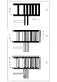
- the white part is the white line 202 of the map image 201
- the shaded part is the white line 212 of the point cloud image 211
- the black part is the white line 202 of the map image 201 and the white line 212 of the point cloud image 211. It is an overlapping part which mutually overlaps.
- the area of the overlapping part is medium.
- the area of the overlapping part is the maximum.
- the deviation amount calculation unit 111 calculates the movement amount of the white line 212 when the area of the overlapping portion is maximum as shown in (3) as the deviation amount between the map data 181 and the measurement data 182.
- step S ⁇ b> 121 the deviation amount calculation unit 111 detects a feature that is a feature common to the map data 181 and the measurement data 182.
- the method for detecting the feature is the same as that in step S111 in FIG. 9 in the first embodiment.
- step S122 the deviation amount calculation unit 111 calculates the overlapping area of the feature objects while moving the feature objects in the measurement data 182.
- the overlapping area of the feature is an area of a portion where the feature in the map data 181 and the feature in the measurement data 182 overlap each other.
- the deviation amount calculation unit 111 calculates the overlapping area of the feature objects as follows.
- the moving direction is the XY direction.
- the XY direction is the horizontal direction.
- the moving range is a predetermined range. Specifically, the movement range is a range from ⁇ to + ⁇ in the X direction, and a range from ⁇ to + ⁇ in the Y direction. ⁇ and ⁇ are predetermined distances.
- the deviation amount calculation unit 111 moves the feature in the measurement data 182 by the unit distance in the X direction or the Y direction within the movement range.
- shift amount calculation part 111 calculates the overlapping area of a feature, whenever the feature in the measurement data 182 is moved.
- the deviation amount calculating unit 111 stores the calculated overlapping area in the storage unit 191 in association with the movement amount.
- the movement amount associated with the overlapping area is the amount that the feature in the measurement data 182 has moved from the original position.
- the amount of movement is represented by a vector.
- step S123 the deviation amount calculation unit 111 selects a movement amount corresponding to the maximum overlapping area.
- the selected movement amount is the shift amount between the map data 181 and the measurement data 182.
- the deviation amount calculation unit 111 selects the maximum overlapping area from the overlapping areas calculated in step S122. Then, the deviation amount calculation unit 111 selects the movement amount associated with the maximum overlapping area. *** Effects of Embodiment 2 *** It is possible to obtain a deviation amount between the map data 181 and the measurement data 182 with high accuracy. As a result, the map data 181 is appropriately updated. *** Other configurations *** The feature moved in step S122 in FIG. 17 may be a feature in the map data 181.
- Embodiment 3 Regarding the form in which the user designates the position of the characteristic object, points different from the first embodiment will be mainly described with reference to FIGS.
- the configuration of the map data update device 100 is the same as that in FIG. 1 and FIG. 2 of the first embodiment.
- the procedure of the map data update method is the same as that in FIG. 4 of the first embodiment.
- step S100 the procedure of the deviation amount calculation process (S100) is different from that of the first embodiment.
- step S200 to step S400 is the same as that in the first embodiment.
- step S1311 the deviation amount calculation unit 111 obtains the position of the feature using the map data 181.
- the deviation amount calculation unit 111 obtains the position of the feature as follows.
- the map data 181 includes feature information of features called marker points.
- Marker points are features that serve as common landmarks between vehicles in an automated driving support system.
- the deviation amount calculation unit 111 selects feature information whose type is a marker point from the map data 181 and extracts position information from the selected feature information.
- the three-dimensional coordinate value indicated by the extracted position information is the position of the feature object.
- step S1312 the deviation amount calculation unit 111 generates a measurement image corresponding to the measurement data 182.
- the display unit 192 displays the measurement image.
- the deviation amount calculation unit 111 generates a point cloud image 211 as shown in FIG. 5 using the three-dimensional point cloud data that is the measurement data 182. Then, the display unit 192 displays the point cloud image 211.
- step S1313 the accepting unit 193 accepts a designated location designated in the measurement image.
- the designated location is a location corresponding to the position of the feature.
- the specified location is specified as follows.
- the user finds a location corresponding to the marker point from the measurement image displayed on the display 904.
- the user operates the input device 905 to designate a location corresponding to the marker point.
- the designated location is the designated location.
- step S1314 the deviation amount calculation unit 111 uses the measurement data 182 to obtain a position corresponding to the designated location.
- the deviation amount calculation unit 111 obtains a position corresponding to the designated location as follows.
- the deviation amount calculation unit 111 selects a measurement point corresponding to the designated location from the point cloud image 211 that is a measurement image.
- the measurement points corresponding to the designated location are the measurement points closest to the designated location or the three measurement points surrounding the designated location.
- the deviation amount calculation unit 111 extracts the three-dimensional coordinate value of the selected measurement point from the measurement data 182.
- shift amount calculation part 111 calculates
- the obtained three-dimensional coordinate value is position information corresponding to the designated location.
- the 3D coordinate value corresponding to the specified location is the 3D coordinate value of the measurement point closest to the specified location.
- the three-dimensional coordinate value corresponding to the designated location is a three-dimensional coordinate value of the center of gravity of a triangle whose apexes are three measurement points surrounding the designated location.
- step S1315 the deviation amount calculation unit 111 calculates the difference between the position of the feature in the map data 181 and the position of the feature in the measurement data 182.
- the calculated difference is a deviation amount between the map data 181 and the measurement data 182.
- the position of the feature in the map data 181 is the position obtained in step S1311.
- the position of the characteristic object in the measurement data 182 is the position obtained in step S1314.
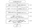
- Example 2> Based on FIG. 19, the procedure of the deviation amount calculation process (S100) will be described.
- step S1321 the deviation amount calculation unit 111 obtains the position of the feature using the measurement data 182.
- the method for obtaining the position of the feature is the same as step S113 of FIG. 9 in the first embodiment.
- step S1322 the deviation amount calculation unit 111 uses the map data 181 to generate a map image 201 as shown in FIG. Then, the display unit 192 displays the map image 201.
- step S ⁇ b> 1323 the deviation amount calculation unit 111 accepts a designated location designated in the map image 201.
- the designated location is a location corresponding to the position of the feature.
- the specified location is specified as follows.
- the user finds a location corresponding to the position of the feature from the map image 201 displayed on the display 904.
- the user operates the input device 905 to designate a location corresponding to the position of the feature object.
- the designated location is the designated location.
- step S1324 the deviation amount calculation unit 111 uses the map data 181 to obtain a position corresponding to the designated location.
- the deviation amount calculation unit 111 obtains a position corresponding to the designated location as follows.
- the deviation amount calculation unit 111 detects from the map data 181 a feature that is a feature located at a specified location.
- the method for detecting the feature is the same as that in step S111 in FIG. 9 in the first embodiment.
- the deviation amount calculation unit 111 calculates the position of the feature in the map data 181.
- the method for calculating the position of the feature object is the same as step S112 in FIG. 9 in the first embodiment.
- step S1325 the deviation amount calculation unit 111 calculates the difference between the position of the feature in the map data 181 and the position of the feature in the measurement data 182.
- the calculated difference is a deviation amount between the map data 181 and the measurement data 182.
- the position of the feature in the map data 181 is the position obtained in step S1324.
- the position of the feature in the measurement data 182 is the position obtained in step S1321.
- Example 3> Based on FIG. 20, the procedure of the deviation amount calculation process (S100) will be described.
- Steps S1331 to S1333 are the same as steps S1322 to S1324 in FIG.
- Steps S1334 to S1336 are the same as Steps S1312 to S1314 in FIG.
- step S1337 the deviation amount calculation unit 111 calculates a difference between the position of the feature in the map data 181 and the position of the feature in the measurement data 182.
- the calculated difference is a deviation amount between the map data 181 and the measurement data 182.
- the position of the feature in the map data 181 is the position obtained in step S1333.
- the position of the feature in the measurement data 182 is the position obtained in step S1336.
- *** Effects of Embodiment 3 *** With respect to a feature that is a feature common to the map data 181 and the measurement data 182, the position of the feature can be appropriately detected. As a result, the map data 181 is appropriately updated. *** Other configurations ***
- the measurement image corresponding to the measurement data 182 may be a captured image based on the captured image data.
- the position information corresponding to the specified location specified in the captured image is obtained as follows.
- the shift amount calculation unit 111 projects the measurement point group onto the captured image using the three-dimensional point group data that is the measurement data 182.
- the measurement point is projected at a location corresponding to the intersection of the image plane corresponding to the captured image and the line-of-sight vector from the camera to the measurement point.
- the deviation amount calculation unit 111 regards the captured image on which the measurement point cloud is projected as the point cloud image 211, and obtains position information corresponding to the designated location.
- the method for obtaining the position information corresponding to the designated location is the same as step S1314 in FIG.
- Embodiment 4 With respect to the form in which the map data 181 is updated when the same difference is extracted a plurality of times, differences from the first embodiment will be mainly described with reference to FIG. *** Explanation of configuration *** The configuration of the map data update device 100 is the same as that in FIG. 1 and FIG. 2 of the first embodiment. *** Explanation of operation *** Based on FIG. 21, the map data update method will be described.
- step S100 to step S300 is executed for each measurement data 182 having different measurement times.
- the contents of step S100 to step S300 are as described in FIG. 4 of the first embodiment.
- step S401 the map data update unit 114 determines whether the same difference has been extracted a plurality of times. Specifically, the map data update unit 114 determines whether the same difference has been extracted three times.
- step S400 If the same difference is extracted a plurality of times, the process proceeds to step S400.
- step S100 If the same difference has not been extracted a plurality of times, the process returns to step S100.
- Step S400 is as described in FIG. 4 of the first embodiment.
- Effects of Embodiment 4 *** Temporary differences caused by the presence of pedestrians or measurement errors in MMS should not be reflected in the map data 181. When the same difference is extracted a plurality of times, the difference is reflected in the map data 181 so that the map data 181 can be appropriately updated. *** Other configurations *** The number of times that the same difference is extracted to update the map data 181 may be two times, three times, or four times or more. *** Supplement to the embodiment *** In the embodiment, the function of the map data update device 100 may be realized by hardware.
- FIG. 22 shows a configuration when the function of the map data update device 100 is realized by hardware.
- the map data update device 100 includes a processing circuit 990.
- the processing circuit 990 is also called a processing circuit.
- the processing circuit 990 is a dedicated electronic circuit that realizes the function of “unit” such as the deviation amount calculation unit 111, the deviation correction unit 112, the difference extraction unit 113, the map data update unit 114, and the storage unit 191.
- the processing circuit 990 is a single circuit, a composite circuit, a programmed processor, a parallel programmed processor, a logic IC, GA, ASIC, FPGA, or a combination thereof.
- GA is an abbreviation for Gate Array
- ASIC is an abbreviation for Application Specific Integrated Circuit
- FPGA is an abbreviation for Field Programmable Gate Array.
- the map data update device 100 may include a plurality of processing circuits that replace the processing circuit 990.
- the plurality of processing circuits share the function of “unit”.
- the functions of the map data update device 100 may be realized by a combination of software and hardware. That is, a part of the function of “unit” may be realized by software, and the rest of the function of “unit” may be realized by hardware.
- the embodiment is an example of a preferred embodiment and is not intended to limit the technical scope of the present invention.
- the embodiment may be implemented partially or in combination with other embodiments.
- the procedure described using the flowchart and the like may be changed as appropriate.
- Map data update device 111 Deviation amount calculation unit, 112 Deviation correction unit, 113 Difference extraction unit, 114 Map data update unit, 181 Map data, 182 Measurement data, 191 Storage unit, 192 Display unit, 193 Reception unit, 201 Map Image, 202 white line, 203 centroid, 211 point cloud image, 212 white line, 213 centroid, 214 measurement point cloud, 215 boundary line, 221 new feature, 222 extinction feature, 810 measurement vehicle, 811 GPS receiver, 812 IMU, 813 odometer, 814 laser scanner, 815 camera, 901 processor, 902 memory, 903 auxiliary storage device, 904 display, 905 input device, 906 communication device, 990 processing circuit.
Landscapes
- Engineering & Computer Science (AREA)
- Radar, Positioning & Navigation (AREA)
- Remote Sensing (AREA)
- Physics & Mathematics (AREA)
- General Physics & Mathematics (AREA)
- Theoretical Computer Science (AREA)
- Automation & Control Theory (AREA)
- Business, Economics & Management (AREA)
- Mathematical Physics (AREA)
- Educational Administration (AREA)
- Educational Technology (AREA)
- Navigation (AREA)
- Instructional Devices (AREA)
- Processing Or Creating Images (AREA)
- Traffic Control Systems (AREA)
- Image Analysis (AREA)
Abstract
Description
基準時刻に存在した地物の位置情報を含む地図データと、前記基準時刻の後の計測時刻に行われる計測によって得られるデータであって前記計測時刻に存在した地物の位置情報を含むデータである計測データとを用いて、前記地図データと前記計測データとに共通する地物の位置のずれ量を算出するずれ量算出部と、
算出されたずれ量に基づいて、前記計測データに含まれる位置情報を修正するずれ修正部と、
前記地図データと修正後の計測データとを用いて、前記基準時刻に存在した地物の集合と前記計測時刻に計測された地物の集合との差分を抽出する差分抽出部と、
抽出された差分に基づいて、前記地図データを更新する地図データ更新部とを備える。
地図データを更新する形態について、図1から図15に基づいて説明する。
***構成の説明***
図1に基づいて、地図データ更新装置100の構成を説明する。
***動作の説明***
地図データ更新装置100の動作は地図データ更新方法に相当する。また、地図データ更新方法の手順は地図データ更新プログラムの手順に相当する。
***実施の形態1の効果***
測量的手法による実測を行わずに、計測データ182を用いて地図データ181を更新することが可能となる。そして、地図データ181の更新に要する時間と手間が軽減される。
***他の構成***
図9のステップS112およびステップS113で算出される特徴物の位置は、特徴物の角の位置に基づく代表位置であってもよい。
***実施の形態1の利用形態***
<利用形態1>
図13に基づいて、実施の形態1の利用形態1を説明する。
<利用形態2>
図14に基づいて、実施の形態1の利用形態2を説明する。
***実施の形態1の要約***
図15に基づいて、実施の形態1の要約を説明する。
(1)MMSで得られた計測データ182の一部と基盤となる地図データ181の一部とを特徴物に基づいて比較する。
(2)比較結果に基づいて、地図データ181の一部を更新する。
(3)地図データ181の更新された一部を地図データ181に反映して、地図データ181を更新する。
地図画像201の白線202と点群画像211の白線212とが重なる部分の面積に基づいて地図データ181と計測データ182とのずれ量を算出する形態について、主に実施の形態1と異なる点を、図16および図17に基づいて説明する。
***構成の説明***
地図データ更新装置100の構成は、実施の形態1の図1および図2と同じである。
***動作の説明***
地図データ更新方法の手順は、実施の形態1の図4と同じである。
***実施の形態2の効果***
地図データ181と計測データ182とのずれ量を高い精度で求めることが可能となる。その結果、地図データ181が適切に更新される。
***他の構成***
図17のステップS122において移動される特徴物は、地図データ181における特徴物であってもよい。
利用者が特徴物の位置を指定する形態について、主に実施の形態1と異なる点を、図18から図20に基づいて説明する。
***構成の説明***
地図データ更新装置100の構成は、実施の形態1の図1および図2と同じである。
***動作の説明***
地図データ更新方法の手順は、実施の形態1の図4と同じである。
<実施例1>
図18に基づいて、ずれ量算出処理(S100)の手順を説明する。
<実施例2>
図19に基づいて、ずれ量算出処理(S100)の手順を説明する。
<実施例3>
図20に基づいて、ずれ量算出処理(S100)の手順を説明する。
***実施の形態3の効果***
地図データ181と計測データ182とに共通する地物である特徴物について、特徴物の位置を適宜に検出することが可能となる。その結果、地図データ181が適切に更新される。
***他の構成***
計測データ182に対応する計測画像は、撮影画像データに基づく撮影画像であってもよい。
同じ差分が複数回抽出された場合に地図データ181を更新する形態について、主に実施の形態1と異なる点を、図21に基づいて説明する。
***構成の説明***
地図データ更新装置100の構成は、実施の形態1の図1および図2と同じである。
***動作の説明***
図21に基づいて、地図データ更新方法を説明する。
***実施の形態4の効果***
歩行者の存在またはMMSにおける計測ミス等によって生じる一時的な差分は、地図データ181に反映するべきではない。同じ差分が複数回抽出された場合にその差分が地図データ181に反映されることにより、地図データ181を適切に更新することが可能となる。
***他の構成***
地図データ181を更新するために同じ差分を抽出する回数は、2回でもよいし、3回でもよいし、4回以上でもよい。
***実施の形態の補足***
実施の形態において、地図データ更新装置100の機能はハードウェアで実現してもよい。
Claims (14)
- 基準時刻に存在した地物の位置情報を含む地図データと、前記基準時刻の後の計測時刻に行われる計測によって得られるデータであって前記計測時刻に存在した地物の位置情報を含むデータである計測データとを用いて、前記地図データと前記計測データとに共通する地物の位置のずれ量を算出するずれ量算出部と、
算出されたずれ量に基づいて、前記計測データに含まれる位置情報を修正するずれ修正部と、
前記地図データと修正後の計測データとを用いて、前記基準時刻に存在した地物の集合と前記計測時刻に存在した地物の集合との差分を抽出する差分抽出部と、
抽出された差分に基づいて、前記地図データを更新する地図データ更新部と
を備える地図データ更新装置。 - 前記ずれ量算出部は、
前記地図データと前記計測データとに共通する地物である特徴物を検出し、
前記地図データにおける前記特徴物の位置と、前記計測データにおける前記特徴物の位置とを算出し
前記地図データにおける前記特徴物の位置と前記計測データにおける前記特徴物の位置との差を、前記ずれ量として算出する
請求項1に記載の地図データ更新装置。 - 前記特徴物の位置は、前記特徴物の重心の位置である
請求項2に記載の地図データ更新装置。 - 前記特徴物の位置は、前記特徴物の角の位置に基づく代表位置である
請求項2に記載の地図データ更新装置。 - 前記ずれ量算出部は、
前記地図データと前記計測データとに共通する地物である特徴物を検出し、
前記地図データにおける前記特徴物と前記計測データにおける前記特徴物とのうちの一方の特徴物を移動させながら、前記地図データにおける前記特徴物と前記計測データにおける前記特徴物とが互いに重なる部分の面積を重なり面積として算出し、
最大の重なり面積に対応する移動量を前記ずれ量として選択する
請求項1に記載の地図データ更新装置。 - 前記特徴物は、規定サイズで区分けされる更新区域毎に検出される
請求項2から請求項5のいずれか1項に記載の地図データ更新装置。 - 前記特徴物は、白線と標識と信号機とのいずれかである
請求項2から請求項6のいずれか1項に記載の地図データ更新装置。 - 前記ずれ量算出部は、
前記地図データを用いて特徴物の位置を求め、
計測画像の中で指定される指定箇所に対応する位置を前記計測データを用いて求め、
前記地図データを用いて求められた位置と前記計測データを用いて求められた位置との差を前記ずれ量として算出する
請求項1に記載の地図データ更新装置。 - 前記ずれ量算出部は、
前記計測データを用いて特徴物の位置を求め、
地図画像の中で指定される指定箇所に対応する位置を前記地図データを用いて求め、
前記地図データを用いて求められた位置と前記計測データを用いて求められた位置との差を前記ずれ量として算出する
請求項1に記載の地図データ更新装置。 - 前記ずれ量算出部は、
地図画像の中で指定される指定箇所に対応する位置を前記地図データを用いて求め、
計測画像の中で指定される指定箇所に対応する位置を前記計測データを用いて求め、
前記地図データを用いて求められた位置と前記計測データを用いて求められた位置との差を前記ずれ量として算出する
請求項1に記載の地図データ更新装置。 - 前記地図データ更新部は、
抽出された差分が、前記基準時刻に存在せず前記計測時刻に存在した新規地物である場合、前記新規地物に対応する位置情報を前記地図データに追加し、
抽出された差分が、前記基準時刻に存在して前記計測時刻に存在しなかった消滅地物である場合、前記消滅地物に対応する位置情報を前記地図データから削除する
請求項1に記載の地図データ更新装置。 - 差分抽出部は、計測時刻が異なる計測データ毎に、前記基準時刻に存在した地物の集合と計測時刻に存在した地物の集合との差分を抽出し、
前記地図データ更新部は、同じ差分が複数回抽出された場合に前記地図データを更新する
請求項1または請求項11に記載の地図データ更新装置。 - ずれ量算出部が、基準時刻に存在した地物の位置情報を含む地図データと、前記基準時刻の後の計測時刻に行われる計測によって得られるデータであって前記計測時刻に存在した地物の位置情報を含むデータである計測データとを用いて、前記地図データと前記計測データとに共通する地物の位置のずれ量を算出し、
ずれ修正部が、算出されたずれ量に基づいて、前記計測データに含まれる位置情報を修正し、
差分抽出部が、前記地図データと修正後の計測データとを用いて、前記基準時刻に存在した地物の集合と前記計測時刻に存在した地物の集合との差分を抽出し、
地図データ更新部が、抽出された差分に基づいて、前記地図データを更新する
地図データ更新方法。 - 基準時刻に存在した地物の位置情報を含む地図データと、前記基準時刻の後の計測時刻に行われる計測によって得られるデータであって前記計測時刻に存在した地物の位置情報を含むデータである計測データとを用いて、前記地図データと前記計測データとに共通する地物の位置のずれ量を算出するずれ量算出部と、
算出されたずれ量に基づいて、前記計測データに含まれる位置情報を修正するずれ修正部と、
前記地図データと修正後の計測データとを用いて、前記基準時刻に存在した地物の集合と前記計測時刻に存在した地物の集合との差分を抽出する差分抽出部と、
抽出された差分に基づいて、前記地図データを更新する地図データ更新部として
コンピュータを機能させるための地図データ更新プログラム。
Priority Applications (4)
| Application Number | Priority Date | Filing Date | Title |
|---|---|---|---|
| KR1020187033526A KR102254787B1 (ko) | 2016-05-30 | 2017-02-10 | 지도 데이터 차분 추출 장치, 지도 데이터 차분 추출 방법 및 기억 매체에 저장된 지도 데이터 차분 추출 프로그램 |
| US16/303,934 US11408740B2 (en) | 2016-05-30 | 2017-02-10 | Map data update apparatus, map data update method, and computer readable medium |
| JP2018520351A JP6877417B2 (ja) | 2016-05-30 | 2017-02-10 | 地図データ更新装置、地図データ更新方法および地図データ更新プログラム |
| EP17806065.3A EP3467806A4 (en) | 2016-05-30 | 2017-02-10 | CARD DATA UPDATE DEVICE, CARD DATA UPDATE PROCEDURE AND CARD DATA UPDATE PROGRAM |
Applications Claiming Priority (2)
| Application Number | Priority Date | Filing Date | Title |
|---|---|---|---|
| JP2016107208 | 2016-05-30 | ||
| JP2016-107208 | 2016-05-30 |
Publications (1)
| Publication Number | Publication Date |
|---|---|
| WO2017208503A1 true WO2017208503A1 (ja) | 2017-12-07 |
Family
ID=60479199
Family Applications (1)
| Application Number | Title | Priority Date | Filing Date |
|---|---|---|---|
| PCT/JP2017/004920 Ceased WO2017208503A1 (ja) | 2016-05-30 | 2017-02-10 | 地図データ更新装置、地図データ更新方法および地図データ更新プログラム |
Country Status (6)
| Country | Link |
|---|---|
| US (1) | US11408740B2 (ja) |
| EP (1) | EP3467806A4 (ja) |
| JP (2) | JP6877417B2 (ja) |
| KR (1) | KR102254787B1 (ja) |
| TW (1) | TWI634315B (ja) |
| WO (1) | WO2017208503A1 (ja) |
Cited By (9)
| Publication number | Priority date | Publication date | Assignee | Title |
|---|---|---|---|---|
| WO2018225446A1 (ja) * | 2017-06-09 | 2018-12-13 | 株式会社デンソー | 地図変化点検出装置 |
| WO2019239477A1 (ja) * | 2018-06-12 | 2019-12-19 | 三菱電機株式会社 | 地図生成装置および地図生成システム |
| WO2020071117A1 (ja) * | 2018-10-01 | 2020-04-09 | パイオニア株式会社 | 情報処理装置 |
| JP2020056657A (ja) * | 2018-10-01 | 2020-04-09 | パイオニア株式会社 | 情報処理装置 |
| CN111506586A (zh) * | 2020-03-27 | 2020-08-07 | 北京百度网讯科技有限公司 | 增量制图的方法、装置、电子设备以及可读存储介质 |
| WO2020175438A1 (ja) * | 2019-02-27 | 2020-09-03 | 愛知製鋼株式会社 | 点群データの取得方法及び点群データ取得システム |
| JPWO2021002190A1 (ja) * | 2019-07-03 | 2021-01-07 | ||
| JP2021117043A (ja) * | 2020-01-23 | 2021-08-10 | 三菱電機株式会社 | データ処理装置、データ処理方法及びデータ処理プログラム |
| WO2026074910A1 (ja) * | 2024-10-03 | 2026-04-09 | ソニーセミコンダクタソリューションズ株式会社 | 情報処理装置および車両 |
Families Citing this family (11)
| Publication number | Priority date | Publication date | Assignee | Title |
|---|---|---|---|---|
| DE102018204500A1 (de) * | 2018-03-23 | 2019-09-26 | Continental Automotive Gmbh | System zur Erzeugung von Konfidenzwerten im Backend |
| CN112634371B (zh) | 2019-09-24 | 2023-12-15 | 阿波罗智联(北京)科技有限公司 | 用于输出信息、标定相机的方法和装置 |
| KR102327185B1 (ko) * | 2019-12-24 | 2021-11-17 | 한국도로공사 | 정밀도로지도 갱신을 위한 객체 변화 탐지 시스템 및 그 방법 |
| JP2022042146A (ja) * | 2020-09-02 | 2022-03-14 | 株式会社トプコン | データ処理装置、データ処理方法およびデータ処理用プログラム |
| CN112086010B (zh) * | 2020-09-03 | 2022-03-18 | 中国第一汽车股份有限公司 | 地图生成方法、装置、设备及存储介质 |
| JP7260575B2 (ja) * | 2021-02-25 | 2023-04-18 | 本田技研工業株式会社 | 地図生成装置 |
| CN119053512A (zh) * | 2022-03-15 | 2024-11-29 | 日本先锋公司 | 信息处理装置、控制方法、程序及存储介质 |
| WO2023175712A1 (ja) * | 2022-03-15 | 2023-09-21 | パイオニア株式会社 | 情報処理装置、制御方法、プログラム及び記憶媒体 |
| WO2023249550A2 (en) * | 2022-06-20 | 2023-12-28 | Grabtaxi Holdings Pte. Ltd. | Method and device for placing road objects on map using sensor information |
| CN115757672A (zh) * | 2022-11-16 | 2023-03-07 | 武汉中海庭数据技术有限公司 | 一种高精度地图数据更新方法及系统 |
| JP7819622B2 (ja) * | 2022-12-09 | 2026-02-25 | 株式会社豊田自動織機 | 自己位置推定装置 |
Citations (7)
| Publication number | Priority date | Publication date | Assignee | Title |
|---|---|---|---|---|
| JP2004101780A (ja) * | 2002-09-09 | 2004-04-02 | Hitachi Ltd | 位置座標補正処理装置及び処理方法 |
| JP2005265494A (ja) * | 2004-03-17 | 2005-09-29 | Hitachi Ltd | 車両位置推定装置およびこれを用いた運転支援装置 |
| WO2007007376A1 (ja) * | 2005-07-07 | 2007-01-18 | Matsushita Electric Industrial Co., Ltd. | 地図情報補正装置および地図情報補正方法、プログラムおよびこれを用いた情報提供装置ならびに情報取得装置 |
| US20070021908A1 (en) * | 2005-07-21 | 2007-01-25 | Jeppesen Sanderson Inc. | System and method for data mapping and map discrepancy reporting |
| JP2009069900A (ja) * | 2007-09-10 | 2009-04-02 | Denso Corp | 車両用ナビゲーション装置 |
| JP2009076096A (ja) | 2008-11-27 | 2009-04-09 | Mitsubishi Electric Corp | 対象特定装置 |
| WO2016027394A1 (ja) * | 2014-08-21 | 2016-02-25 | パナソニックIpマネジメント株式会社 | 情報管理装置、車両、および、情報管理方法 |
Family Cites Families (19)
| Publication number | Priority date | Publication date | Assignee | Title |
|---|---|---|---|---|
| JPH0648492B2 (ja) | 1988-08-09 | 1994-06-22 | 東京電力株式会社 | 図面補正装置 |
| JP2859004B2 (ja) | 1991-08-30 | 1999-02-17 | 東京瓦斯株式会社 | 図形処理装置 |
| JPH05181411A (ja) | 1991-12-27 | 1993-07-23 | Toshiba Corp | 地図情報照合更新方式 |
| JPH09179967A (ja) | 1995-12-27 | 1997-07-11 | Tokyo Gas Co Ltd | 地図データ修正方法 |
| JPH09319855A (ja) | 1996-05-29 | 1997-12-12 | Hitachi Ltd | 地図作成装置及び方法 |
| JP4088386B2 (ja) | 1999-04-28 | 2008-05-21 | 株式会社日立製作所 | 地図情報更新方法 |
| JP2001126066A (ja) | 1999-10-27 | 2001-05-11 | Nec Corp | 集積回路の画像位置ずれ算出装置及び算出方法 |
| JP2005345527A (ja) | 2004-05-31 | 2005-12-15 | Matsushita Electric Ind Co Ltd | 地図情報補正装置および地図情報補正方法、プログラムおよびこれを用いた情報提供装置ならびに情報取得装置 |
| JP2006208223A (ja) | 2005-01-28 | 2006-08-10 | Aisin Aw Co Ltd | 車両位置認識装置及び車両位置認識方法 |
| JP4103898B2 (ja) | 2005-04-12 | 2008-06-18 | 株式会社日立製作所 | 地図情報更新方法及び地図更新装置 |
| JP4912279B2 (ja) | 2007-11-21 | 2012-04-11 | 三菱電機株式会社 | 地理空間データ補正装置 |
| EP2306423B1 (en) | 2008-07-10 | 2013-04-10 | Mitsubishi Electric Corporation | Train-of-vehicle travel support device |
| TWI382155B (zh) * | 2008-12-03 | 2013-01-11 | Mitac Int Corp | Map information update device and method |
| CN102246159A (zh) | 2008-12-09 | 2011-11-16 | 通腾北美有限公司 | 产生测地参考数据库产品的方法 |
| JP2010176645A (ja) | 2009-02-02 | 2010-08-12 | Panasonic Corp | 画像認識方法および画像認識装置 |
| JP5088592B2 (ja) * | 2010-04-28 | 2012-12-05 | アイシン・エィ・ダブリュ株式会社 | 自車位置認識装置及び自車位置認識プログラム |
| JP5947236B2 (ja) * | 2013-03-15 | 2016-07-06 | 株式会社トヨタマップマスター | 交差点目印データ作成装置及びその方法、並びに交差点の目印データを作成するためのコンピュータプログラム及びコンピュータプログラムを記録した記録媒体 |
| WO2014148394A1 (ja) * | 2013-03-19 | 2014-09-25 | 株式会社日立国際電気 | 画像表示装置および画像表示方法 |
| US10948302B2 (en) * | 2015-08-03 | 2021-03-16 | Tomtom Global Content B.V. | Methods and systems for generating and using localization reference data |
-
2017
- 2017-02-10 EP EP17806065.3A patent/EP3467806A4/en active Pending
- 2017-02-10 JP JP2018520351A patent/JP6877417B2/ja active Active
- 2017-02-10 WO PCT/JP2017/004920 patent/WO2017208503A1/ja not_active Ceased
- 2017-02-10 US US16/303,934 patent/US11408740B2/en active Active
- 2017-02-10 KR KR1020187033526A patent/KR102254787B1/ko not_active Expired - Fee Related
- 2017-02-22 TW TW106105855A patent/TWI634315B/zh not_active IP Right Cessation
-
2019
- 2019-12-20 JP JP2019229856A patent/JP6739613B2/ja active Active
Patent Citations (7)
| Publication number | Priority date | Publication date | Assignee | Title |
|---|---|---|---|---|
| JP2004101780A (ja) * | 2002-09-09 | 2004-04-02 | Hitachi Ltd | 位置座標補正処理装置及び処理方法 |
| JP2005265494A (ja) * | 2004-03-17 | 2005-09-29 | Hitachi Ltd | 車両位置推定装置およびこれを用いた運転支援装置 |
| WO2007007376A1 (ja) * | 2005-07-07 | 2007-01-18 | Matsushita Electric Industrial Co., Ltd. | 地図情報補正装置および地図情報補正方法、プログラムおよびこれを用いた情報提供装置ならびに情報取得装置 |
| US20070021908A1 (en) * | 2005-07-21 | 2007-01-25 | Jeppesen Sanderson Inc. | System and method for data mapping and map discrepancy reporting |
| JP2009069900A (ja) * | 2007-09-10 | 2009-04-02 | Denso Corp | 車両用ナビゲーション装置 |
| JP2009076096A (ja) | 2008-11-27 | 2009-04-09 | Mitsubishi Electric Corp | 対象特定装置 |
| WO2016027394A1 (ja) * | 2014-08-21 | 2016-02-25 | パナソニックIpマネジメント株式会社 | 情報管理装置、車両、および、情報管理方法 |
Non-Patent Citations (1)
| Title |
|---|
| See also references of EP3467806A4 |
Cited By (17)
| Publication number | Priority date | Publication date | Assignee | Title |
|---|---|---|---|---|
| WO2018225446A1 (ja) * | 2017-06-09 | 2018-12-13 | 株式会社デンソー | 地図変化点検出装置 |
| US11270131B2 (en) | 2017-06-09 | 2022-03-08 | Denso Corporation | Map points-of-change detection device |
| WO2019239477A1 (ja) * | 2018-06-12 | 2019-12-19 | 三菱電機株式会社 | 地図生成装置および地図生成システム |
| JPWO2019239477A1 (ja) * | 2018-06-12 | 2020-12-17 | 三菱電機株式会社 | 地図生成装置および地図生成システム |
| WO2020071117A1 (ja) * | 2018-10-01 | 2020-04-09 | パイオニア株式会社 | 情報処理装置 |
| JP2020056657A (ja) * | 2018-10-01 | 2020-04-09 | パイオニア株式会社 | 情報処理装置 |
| US12105201B2 (en) | 2018-10-01 | 2024-10-01 | Pioneer Corporation | Information processing device |
| EP3862721A4 (en) * | 2018-10-01 | 2022-07-13 | Pioneer Corporation | INFORMATION PROCESSING DEVICE |
| WO2020175438A1 (ja) * | 2019-02-27 | 2020-09-03 | 愛知製鋼株式会社 | 点群データの取得方法及び点群データ取得システム |
| US11933633B2 (en) | 2019-02-27 | 2024-03-19 | Aichi Steel Corporation | Point cloud data acquiring method and point cloud data acquiring system |
| JPWO2021002190A1 (ja) * | 2019-07-03 | 2021-01-07 | ||
| JP7211513B2 (ja) | 2019-07-03 | 2023-01-24 | 株式会社デンソー | 地図データ生成装置 |
| JP7308772B2 (ja) | 2020-01-23 | 2023-07-14 | 三菱電機株式会社 | データ処理装置、データ処理方法及びデータ処理プログラム |
| JP2021117043A (ja) * | 2020-01-23 | 2021-08-10 | 三菱電機株式会社 | データ処理装置、データ処理方法及びデータ処理プログラム |
| CN111506586B (zh) * | 2020-03-27 | 2023-09-22 | 阿波罗智能技术(北京)有限公司 | 增量制图的方法、装置、电子设备以及可读存储介质 |
| CN111506586A (zh) * | 2020-03-27 | 2020-08-07 | 北京百度网讯科技有限公司 | 增量制图的方法、装置、电子设备以及可读存储介质 |
| WO2026074910A1 (ja) * | 2024-10-03 | 2026-04-09 | ソニーセミコンダクタソリューションズ株式会社 | 情報処理装置および車両 |
Also Published As
| Publication number | Publication date |
|---|---|
| KR20180132917A (ko) | 2018-12-12 |
| US20200318975A1 (en) | 2020-10-08 |
| KR102254787B1 (ko) | 2021-05-21 |
| JP6877417B2 (ja) | 2021-05-26 |
| US11408740B2 (en) | 2022-08-09 |
| JPWO2017208503A1 (ja) | 2018-09-27 |
| EP3467806A4 (en) | 2019-06-05 |
| TWI634315B (zh) | 2018-09-01 |
| TW201741629A (zh) | 2017-12-01 |
| EP3467806A1 (en) | 2019-04-10 |
| JP2020052431A (ja) | 2020-04-02 |
| JP6739613B2 (ja) | 2020-08-12 |
Similar Documents
| Publication | Publication Date | Title |
|---|---|---|
| JP6739613B2 (ja) | 地図データ差分抽出装置、地図データ差分抽出方法および地図データ差分抽出プログラム | |
| JP5116555B2 (ja) | 位置標定装置、位置標定システム、標定サーバ装置および位置標定方法 | |
| US8571265B2 (en) | Measurement apparatus, measurement method, and feature identification apparatus | |
| CN105512646B (zh) | 一种数据处理方法、装置及终端 | |
| US20150071493A1 (en) | Information processing apparatus, control method of the information processing apparatus, and storage medium | |
| JP5501101B2 (ja) | 位置標定装置、位置標定方法および位置標定プログラム | |
| US10210411B2 (en) | Method and apparatus for establishing feature prediction accuracy | |
| JP7215448B2 (ja) | 検出器の姿勢・位置検出装置 | |
| CN111536990A (zh) | 在传感器之间的在线外参误标定检测 | |
| US11250622B2 (en) | Map creation system and map creation method | |
| CN110608746B (zh) | 用于确定机动车的位置的方法和装置 | |
| US20200200870A1 (en) | Radar Sensor Misalignment Detection for a Vehicle | |
| KR102136924B1 (ko) | 피테스트 카메라 모듈의 상대 위치 산출 정확도를 평가하기 위한 평가 방법 및 시스템 | |
| KR20200094841A (ko) | 자율주행차량의 환경특징 기반 위치인식 장치 및 방법 | |
| JP2018189463A (ja) | 車両位置推定装置及びプログラム | |
| JP2012242318A (ja) | 位置補正データ生成装置、位置標定装置、ユーザインタフェース装置、位置補正データ生成装置の位置補正データ生成方法、位置標定装置の位置標定方法、ユーザインタフェース装置の情報処理方法、位置補正データ生成プログラム、位置標定プログラムおよびユーザインタフェースプログラム | |
| JP6370234B2 (ja) | 地図データ生成装置、地図データ生成方法及び地図データ生成用コンピュータプログラムならびに車両位置検出装置 | |
| JP4596566B2 (ja) | 自車情報認識装置及び自車情報認識方法 | |
| JP6632413B2 (ja) | 点群位置合わせ装置および点群位置合わせプログラム | |
| WO2016157802A1 (ja) | 情報処理装置、情報処理システム、情報処理方法、及び、記録媒体 | |
| CN114281832A (zh) | 基于定位结果的高精地图数据更新方法、装置和电子设备 | |
| WO2022244134A1 (ja) | 情報処理装置及び情報処理方法 | |
| CN116245510B (zh) | 基于车路协同的道路资产检测管理方法、装置和存储介质 | |
| CN115962776B (zh) | 移动设备定位方法、装置及计算机可读取存储介质 | |
| JP7562816B1 (ja) | 点群処理装置、点群処理方法及びプログラム |
Legal Events
| Date | Code | Title | Description |
|---|---|---|---|
| ENP | Entry into the national phase |
Ref document number: 2018520351 Country of ref document: JP Kind code of ref document: A |
|
| ENP | Entry into the national phase |
Ref document number: 20187033526 Country of ref document: KR Kind code of ref document: A |
|
| 121 | Ep: the epo has been informed by wipo that ep was designated in this application |
Ref document number: 17806065 Country of ref document: EP Kind code of ref document: A1 |
|
| NENP | Non-entry into the national phase |
Ref country code: DE |
|
| ENP | Entry into the national phase |
Ref document number: 2017806065 Country of ref document: EP Effective date: 20190102 |