WO2017209509A1 - 영상 처리 장치, 그의 영상 처리 방법 및 비일시적 컴퓨터 판독가능 기록매체 - Google Patents
영상 처리 장치, 그의 영상 처리 방법 및 비일시적 컴퓨터 판독가능 기록매체 Download PDFInfo
- Publication number
- WO2017209509A1 WO2017209509A1 PCT/KR2017/005684 KR2017005684W WO2017209509A1 WO 2017209509 A1 WO2017209509 A1 WO 2017209509A1 KR 2017005684 W KR2017005684 W KR 2017005684W WO 2017209509 A1 WO2017209509 A1 WO 2017209509A1
- Authority
- WO
- WIPO (PCT)
- Prior art keywords
- image
- parameter
- overlap region
- derived
- processor
- Prior art date
- Legal status (The legal status is an assumption and is not a legal conclusion. Google has not performed a legal analysis and makes no representation as to the accuracy of the status listed.)
- Ceased
Links
Images


Classifications
-
- H—ELECTRICITY
- H04—ELECTRIC COMMUNICATION TECHNIQUE
- H04N—PICTORIAL COMMUNICATION, e.g. TELEVISION
- H04N23/00—Cameras or camera modules comprising electronic image sensors; Control thereof
- H04N23/95—Computational photography systems, e.g. light-field imaging systems
- H04N23/951—Computational photography systems, e.g. light-field imaging systems by using two or more images to influence resolution, frame rate or aspect ratio
-
- H—ELECTRICITY
- H04—ELECTRIC COMMUNICATION TECHNIQUE
- H04N—PICTORIAL COMMUNICATION, e.g. TELEVISION
- H04N23/00—Cameras or camera modules comprising electronic image sensors; Control thereof
- H04N23/60—Control of cameras or camera modules
- H04N23/67—Focus control based on electronic image sensor signals
- H04N23/676—Bracketing for image capture at varying focusing conditions
-
- H—ELECTRICITY
- H04—ELECTRIC COMMUNICATION TECHNIQUE
- H04N—PICTORIAL COMMUNICATION, e.g. TELEVISION
- H04N23/00—Cameras or camera modules comprising electronic image sensors; Control thereof
- H04N23/70—Circuitry for compensating brightness variation in the scene
-
- H—ELECTRICITY
- H04—ELECTRIC COMMUNICATION TECHNIQUE
- H04N—PICTORIAL COMMUNICATION, e.g. TELEVISION
- H04N23/00—Cameras or camera modules comprising electronic image sensors; Control thereof
- H04N23/70—Circuitry for compensating brightness variation in the scene
- H04N23/73—Circuitry for compensating brightness variation in the scene by influencing the exposure time
-
- H—ELECTRICITY
- H04—ELECTRIC COMMUNICATION TECHNIQUE
- H04N—PICTORIAL COMMUNICATION, e.g. TELEVISION
- H04N25/00—Circuitry of solid-state image sensors [SSIS]; Control thereof
- H04N25/50—Control of the SSIS exposure
- H04N25/57—Control of the dynamic range
-
- H—ELECTRICITY
- H04—ELECTRIC COMMUNICATION TECHNIQUE
- H04N—PICTORIAL COMMUNICATION, e.g. TELEVISION
- H04N25/00—Circuitry of solid-state image sensors [SSIS]; Control thereof
- H04N25/50—Control of the SSIS exposure
- H04N25/57—Control of the dynamic range
- H04N25/58—Control of the dynamic range involving two or more exposures
- H04N25/581—Control of the dynamic range involving two or more exposures acquired simultaneously
- H04N25/585—Control of the dynamic range involving two or more exposures acquired simultaneously with pixels having different sensitivities within the sensor, e.g. fast or slow pixels or pixels having different sizes
-
- H—ELECTRICITY
- H04—ELECTRIC COMMUNICATION TECHNIQUE
- H04N—PICTORIAL COMMUNICATION, e.g. TELEVISION
- H04N25/00—Circuitry of solid-state image sensors [SSIS]; Control thereof
- H04N25/50—Control of the SSIS exposure
- H04N25/57—Control of the dynamic range
- H04N25/58—Control of the dynamic range involving two or more exposures
- H04N25/587—Control of the dynamic range involving two or more exposures acquired sequentially, e.g. using the combination of odd and even image fields
- H04N25/589—Control of the dynamic range involving two or more exposures acquired sequentially, e.g. using the combination of odd and even image fields with different integration times, e.g. short and long exposures
Definitions
- the present disclosure relates to an image processing apparatus, an image processing method thereof, and a non-transitory computer readable recording medium, and more particularly, an image processing apparatus capable of improving image quality of a non-overlap region of a plurality of images, and an image processing method thereof. And non-transitory computer readable recording medium.
- the present disclosure is directed to solving the above-described problem, and includes an image processing apparatus capable of deriving a relationship between overlap regions and correcting or correcting not only the overlap region but also the non-overlap region by using the derived relationship. It is an object to provide a temporary computer readable recording medium.
- An image processing apparatus for achieving the above object, the image input unit for receiving the first image and the second image and the overlap region of each of the first image and the second image, A processor for deriving a relation parameter from the overlap region of the first image and the overlap region of the second image, and correcting at least one of the first image and the second image using the derived relation parameter It may include.
- the processor may determine a relationship parameter to be derived using the difference between the first image and the second image, and the relationship parameter may include an overlap region of one of the first image and the second image and overlap the remaining image. It may be a parameter for converting to an area.
- the processor may further correct the non-overlap area of at least one of the first image and the second image by using the derived relationship parameter, and the corrected non-overlap area, the first image, and the first image may be corrected.
- One overlap region of two images may be synthesized and output.
- the relationship parameter may be at least one of a blur parameter, a noise parameter, a motion blur parameter, a saturation parameter, a contrast ratio parameter, and a dynamic range parameter.
- the processor may be further configured to derive a blur parameter between an overlap region of the first image and an overlap region of the second image when the field of view (FoV) of the first image is greater than the field of view of the second image.
- the non-overlap area of the first image may be corrected using the blurred blur parameter.
- the processor derives a noise parameter between the overlap region of the first image and the overlap region of the second image,
- the non-overlap area of the second image may be corrected by using the noise parameter.
- the processor may be further configured to derive a noise parameter between an overlap region of the first image and an overlap region of the second image when the sensitivity of the first image is higher than the sensitivity of the second image.
- the non-overlap area of the second image may be corrected using.
- the processor derives a motion blur parameter between the overlap region of the first image and the overlap region of the second image,
- the non-overlap area of the first image may be corrected by using the motion blur parameter.
- the processor derives a noise parameter between the overlap region of the first image and the overlap region of the second image, and derives the derived noise parameter.
- the non-overlap area of the second image may be corrected using the noise parameter.
- the processor may determine the correction result image that minimizes a cost composed of a value related to a difference between a product of the image to be corrected and the derived relation parameter and a product of a composite product, and a value related to a slope of the correction result image.
- the at least one image of the first image and the second image may be corrected.
- the image processing method of the image processing apparatus for achieving the above object, receiving a first image and a second image, overlap regions of each of the first image and the second image Detecting a relationship; deriving a relationship parameter using the overlap area of the first image and the overlap area of the second image; and at least one of the first image and the second image using the derived relationship parameter.
- Compensating the image may include.
- the method may further include determining a relationship parameter to be derived by using a difference between the first image and the second image, wherein the relationship parameter includes an overlap region of one of the first image and the second image as the remaining image. It may be a parameter for converting to an overlap region of.
- the correcting may include correcting a non-overlap region of at least one of the first image and the second image by using the derived relationship parameter, and correcting the corrected non-overlap region and the first image. And synthesizing and outputting an overlap region of one of the second images.
- the relationship parameter may be at least one of a blur parameter, a noise parameter, a motion blur parameter, a saturation parameter, a contrast ratio parameter, and a dynamic range parameter.
- the deriving may include deriving a blur parameter between an overlap region of the first image and an overlap region of the second image when the field of view (FoV) of the first image is greater than the field of view of the second image.
- the non-overlap region of the first image may be corrected using the derived blur parameter.
- the deriving may include deriving a noise parameter between an overlap region of the first image and an overlap region of the second image if the angle of view (FoV) of the first image is greater than the angle of view of the second image.
- the non-overlap region of the second image may be corrected using the derived noise parameter.
- the deriving may include deriving and correcting a noise parameter between an overlap region of the first image and an overlap region of the second image when the sensitivity of the first image is higher than that of the second image.
- the non-overlap area of the second image may be corrected using the derived noise parameter.
- the deriving may include deriving a motion blur parameter between an overlap region of the first image and an overlap region of the second image if the exposure time of the first image is longer than the exposure time of the second image, In the correcting, the non-overlap region of the first image may be corrected using the derived motion blur parameter.
- the deriving may include deriving a noise parameter between an overlap region of the first image and an overlap region of the second image when the exposure time of the first image is longer than that of the second image.
- the non-overlap area of the second image may be corrected using the derived noise parameter.
- a non-transitory computer readable recording medium including a program for executing an image processing method of an image processing apparatus according to an embodiment of the present disclosure for achieving the above object may receive a first image and a second image.
- the method may further include: detecting overlap regions of each of the first image and the second image, deriving a relationship parameter using the overlap region of the first image and the overlap region of the second image, and the derived relationship parameter.
- an image processing method comprising correcting at least one of the first image and the second image by using a second image.
- the image processing apparatus may improve the image quality of the overlap region as well as the non-overlap region of the image by taking advantage of different optical characteristics without losing the field of view (FoV).
- FIG. 1 is a diagram illustrating a case where an image processing apparatus according to an embodiment of the present disclosure is implemented as a smartphone;
- FIG. 2 is a schematic block diagram illustrating a configuration of an image processing apparatus according to an embodiment of the present disclosure
- FIG. 3 is a block diagram for explaining in detail the configuration of an image processing apparatus according to an embodiment of the present disclosure
- 4A to 4C are conceptual diagrams for describing an operation of an image processing apparatus according to an exemplary embodiment.
- 5A and 5B illustrate an image to which an image processing method is applied according to an embodiment of the present disclosure
- 6A and 6B are diagrams for describing deriving relationship parameters according to an embodiment of the present disclosure.
- FIGS. 7A to 11 are diagrams illustrating an image processing process, according to various embodiments of the present disclosure.
- 12 and 13 are flowcharts illustrating an image processing method according to various embodiments of the present disclosure.
- first and second may be used to describe various components, but the components are not limited by the terms. The terms are only used to distinguish one component from another.
- first component may be referred to as the second component, and similarly, the second component may also be referred to as the first component.
- the correction of an image may be interpreted not only to improve or improve an image quality, but also to correct an image.
- FIG. 1 is a diagram illustrating a case in which the image processing apparatus 100 according to an embodiment of the present disclosure is implemented as a smartphone.
- the image processing apparatus 100 according to an embodiment of the present disclosure may be implemented not only as a smartphone but also as a tablet, a digital camera, a PDA, a smart glass, and the like.
- the image processing apparatus 100 is illustrated as a smartphone that directly generates a plurality of input images through a plurality of cameras.
- the image processing apparatus 100 does not necessarily generate a plurality of input images directly.
- the image processing apparatus 100 may receive a plurality of input images from the outside.
- the image processing apparatus 100 may not necessarily generate a plurality of input images through the plurality of cameras.
- the image processing apparatus 100 may generate a plurality of images having overlap regions and non-overlap regions using a single camera. However, when using a single camera, a plurality of images need to be taken under different optical conditions.
- the image processing apparatus 100 may include an image input unit 110 and a processor 120.
- the image input unit 110 may receive the first image and the second image.
- the first image and the second image may be images captured to have regions overlapping each other.
- the first image and the second image may be images captured under different optical characteristic conditions.
- the first image and the second image may be images captured at different focal lengths with respect to the same object.
- the processor 120 may detect the overlap area by matching the received first image and the second image.
- the processor 120 may derive a relationship parameter by using the overlap region of the first image and the overlap region of the second image.
- the processor 120 may correct at least one of the first image and the second image by using the derived relationship parameter.
- the processor 120 may determine a relationship parameter to be derived using the difference between the first image and the second image.
- the relationship parameter may be a parameter for converting an overlap region of one of the first image and the second image into an overlap region of the other image.
- the relationship parameter may be at least one of a blur parameter, a noise parameter, a motion blur parameter, a saturation parameter, a contrast ratio parameter, and a dynamic range parameter.
- the processor 120 may correct the non-overlap area of at least one of the first image and the second image by using the derived relationship parameter.
- the processor 120 may synthesize and output the corrected non-overlap region and one overlap region of the first image and the second image.
- the image processing apparatus 100 may derive a relationship between overlap areas of a plurality of images, and correct not only the overlap area but also the non-overlap area by using the derived relationship between the overlap areas. .
- the image processing apparatus 100 may include an image input unit 110, a processor 120, a plurality of photographing units 131 and 133, a storage unit 140, a display unit 150, and a communication unit 160. ) And the manipulation inputter 170.
- the image processing apparatus 100 is not limited to including all of the above configurations.
- the image processing apparatus 100 according to an exemplary embodiment may be implemented in a form that does not include the plurality of photographing units 131 and 133 or the communication unit 170.
- the image processing apparatus 100 may further include a configuration not shown in the embodiment of FIG. 3.
- the image processing apparatus 100 may further include a configuration such as a USB interface (not shown) and a depth sensor (not shown).
- the description of the image input unit 110 will be omitted since it overlaps with the description of FIG. 2.
- a plurality of images are input to the image input unit 110 directly from the plurality of capture units 131 and 133, but images captured by the plurality of capture units 131 and 133 are stored. It may be stored in the unit 140 and then input to the image input unit 110. As another example, at least one of a plurality of images may be received through the communication unit 160 and input to the image input unit 110.
- the plurality of photographing units 131 and 133 may photograph a subject to generate a plurality of images.
- the image processing apparatus 100 includes two photographing units 131 and 133, but may include a larger number of photographing units.
- the single photographing unit may be implemented by the image processing apparatus 100 generating a plurality of images under different optical conditions.
- the plurality of photographing units 131 and 133 may be implemented as photographing devices having different optical characteristics.
- the plurality of photographing units 131 and 133 may be implemented as lenses having different focal lengths.
- the first photographing unit 131 may photograph a subject by using a wide-angle lens
- the second photographing unit 133 may photograph a subject by using a telephoto lens.
- the plurality of photographing units 131 and 133 may be implemented as photographing devices having different sensitivity and different shutter speeds (exposure time).
- one of the plurality of photographing units 131 and 133 may be a low resolution camera having a very small size used for improving image quality.
- the storage unit 140 may store various data such as an operating system (OS), various programs, user setting data, and the like.
- OS operating system
- the storage 140 may store a plurality of images photographed by the plurality of photographing units 131 and 133.
- the storage 140 may provide the plurality of stored images to the processor 120.
- the storage 140 may not only be implemented as a storage medium in the image processing apparatus 100 but also as an external storage medium.
- external storage media include a removable disk including a USB memory and a web server connected through a network.
- the display unit 150 may display an image captured / processed by the image processing apparatus 100.
- the display unit 150 may display a user interface window for selecting various functions provided by the image processing apparatus 100.
- the display unit 150 may be implemented in various forms such as liquid crystal display (LCD), organic light emitting diodes (OLED), active-matrix organic light-emitting diode (AM-OLED), plasma display panel (PDP), and the like. have.
- the display unit 150 may be implemented in the form of a touch screen forming a mutual layer structure together with the touch pad, and the touch screen may be configured to detect a touch input position, an area, and even a pressure of the touch input. In this case, the display unit 150 may also perform a function of the operation input unit 170 to be described later.
- the communicator 160 may communicate with an external device through a wired or wireless network.
- the communication unit 160 may receive a plurality of images from an external device, and transmit the synthesized image to the external device.
- the communication unit 160 may use various methods such as near field communication (NFC), wireless LAN (InfraRed, IR) communication, Zigbee communication, WiFi, and Bluetooth as a wireless communication method.
- NFC near field communication
- IR wireless LAN
- WiFi Zigbee communication
- Bluetooth Bluetooth
- the communication unit 160 may use a mobile communication scheme (eg, GSM, UMTS, LTE, LTE-A, WiBRO, etc.).
- the communication unit 160 may use various methods such as HDMI (High Definition Multimedia Interface), Low Voltage Differential Signaling (LVDS), Local Area Network (LAN), and Universal Serial Bus (USB).
- HDMI High Definition Multimedia Interface
- LVDS Low Voltage Differential Signaling
- LAN Local Area Network
- USB Universal Serial Bus
- the manipulation input unit 170 may receive a function selection and a control command for the corresponding function from the user.
- the function may include a photographing function, a correction function, a synthesis function, and the like.
- the manipulation input unit 170 may receive a control command through a user interface window displayed on the display unit 150.
- the processor 120 may control the remaining components of the image processing apparatus 100. For example, the processor 120 may synthesize the corrected non-overlap area and one overlap area of the first image and the second image, and control the display 150 to display the synthesized image.
- the processor 120 may be implemented as a single CPU to perform both image processing and control operations for other components, and may include a plurality of processors such as a CPU, a GPU, an image signal processor (ISP), and an IP for performing specific functions. May be implemented.
- FIGS. 4A through 4C are conceptual diagrams for describing an operation of the image processing apparatus 100 according to an exemplary embodiment.
- the image processing apparatus 100 according to an exemplary embodiment may improve the image quality of the non-overlap region through a correlation model between the overlap regions.
- the first image 410 may be a wide image captured by a wide angle lens.
- the second image 420 may be a tele image captured by a telephoto lens.
- the first image 410 may be divided into an overlap region 413 that does not overlap the overlap region 411 overlapping the second image 420.
- the second image 420 is illustrated as an overlap region in which the entire area overlaps the first image 410.
- the processor 120 may derive a relation parameter or a relation function using the overlap region 411 of the first image and the overlap region 420 of the second image.
- the processor 120 may derive a relation parameter or a relation function for converting the overlap region 420 of the second image having the high sharpness of the image into the overlap region 411 of the first image having the low sharpness of the image. have.
- the processor 120 may correct the overlap region 411 and the non-overlap region 413 of the first image 410 having low clarity by using the inverse function of the derived relation function. have. That is, the processor 120 may correct the sharpness of the corrected first image 430 to be close to the sharpness of the second image 420.
- Equation (1) When the derived relationship parameter is K, the image to be corrected (in whole or in part) is referred to as g, and the corrected image is referred to as f, these relations can be described as in Equation (1).
- ⁇ is noise
- Kf is a convolution of K and f.
- the processor 120 may derive a relationship parameter K for converting a second image having high definition into a first image g having low definition. Therefore, the first image g having low clarity and the image f having been corrected may have a relationship as shown in Equation 1 below.
- Equation 2 conceptually expresses an equation for the processor 120 to find f in Equation 1.
- the processor 120 may correct the image by searching for the image g to be corrected and f where the value Kf to which the relation parameter is applied to the corrected image is as equal as possible.
- the value related to the difference between the image g to be corrected and the value Kf to which the relation parameter is applied to the corrected image may be referred to as a data cost C data .
- the processor 120 may consider an adjustment cost C regularization corresponding to a constraint.
- the processor 120 may generate the corrected image f to minimize the data cost and the adjustment cost by using Equation 3.
- Equation 3 corresponds to the data cost and the second term corresponds to the adjusted cost.
- ⁇ is a value corresponding to a weight or coefficient of the adjustment cost, and the processor 120 may calculate an optimal ⁇ . The processor 120 may find f with less gradient through the adjustment cost.
- the processor 120 may generate a corrected image f to minimize the data cost and the adjustment cost by using Equation 4.
- Equation 3 the square of L2 norm, which is the root of the sum of squares of each element as the adjustment cost, is used.
- Equation 4 the square of L1 norm is used as the adjustment cost, which is the sum of the absolute values of each element.
- the processor 120 may generate a corrected image f to minimize the data cost and the adjustment cost by using Equation 5.
- the processor 120 may consider both adjustment cost terms as described above. Since the two adjustment cost terms are in a trade-off relationship with each other, the processor 120 may calculate an optimal f by considering both of these adjustment cost terms. For example, L2 norm can calculate analytical solutions, which has advantages in computational efficiency. L1 norm has the advantage of being more robust because it is less efficient in computation but insensitive to error values. Therefore, the processor 120 may perform correction appropriate to each image by adjusting ⁇ and ⁇ .
- FIG. 5A and 5B illustrate an actual image to which an image processing method is applied according to an exemplary embodiment.
- a first image 510 that is a wide image and a second image 520 that is a tele image are illustrated.
- the overlap region 511 of the first image is the same as the photographing target of the second image 520.
- the processor 120 may derive a parameter of a point spread function (PSF), which is a function related to blur, by using the overlap region of the second image 520 and the overlap region 511 of the first image.
- PSF point spread function
- the processor 120 may derive a parameter of the PSF capable of generating the overlap region 511 of the first image by applying the PSF to the second image 520.
- the processor 120 may generate the corrected image 530 by applying an inverse function of the PSF having the derived parameter to the first image 510.
- FIG. 5B only the overlap region 511 is illustrated to clearly illustrate the correction effect.
- the processor 120 uses the inverse function of the PSF derived through the relationship between the overlap regions to select the non-overlap region of the first image 510. Of course, it can be corrected.
- 6A and 6B are diagrams for describing derivation of relationship parameters according to an embodiment of the present disclosure.
- 6A and 6B illustrate an embodiment of deriving a parameter of a PSF function for blur processing.
- the parameter of the PSF function may be a variance value of the Gaussian blur function.
- the PSF having a predetermined parameter is applied regardless of which image is corrected.
- the image processing apparatus 100 may derive a relationship between overlap regions of a plurality of images to derive a PSF parameter suitable for the corresponding image.
- a conventional image processing apparatus performs correction using a PSF having a predetermined parameter such as 0.7 or 2.0 regardless of which image is processed.
- the image processing apparatus 100 may derive that the optimal parameter is 1.619 through a relationship between overlap regions of a plurality of images.
- the image processing apparatus 100 may derive an optimum parameter 1.18 by using the relationship between overlap regions of the images of FIG. 6B. Therefore, as in the image processing apparatus 100 according to an exemplary embodiment, a relationship between overlap regions of a plurality of images may be derived, and thus more accurate and appropriate correction may be performed for each image. In addition, the image processing apparatus 100 according to an exemplary embodiment may perform correction for not only the overlap region but also the non-overlap region by using the relationship parameter appropriately derived for the image.
- FIG. 7A illustrates an embodiment in which the image processing apparatus 100 improves the sharpness of a wide image by using a tele image.
- the processor 120 may use a tele image to display a normal image because a difference in the field of view (FoV) between two images input to the image input unit 110 exists. You can also improve the sharpness.
- FoV field of view
- tele image and wide image can be captured from a photographing element having a telephoto lens and a wide-angle lens, respectively.
- the image processing apparatus 100 may be implemented as a smart phone having a dual camera.
- wide images may be taken with a high resolution camera, and tele images may be taken with a low resolution camera for improving image quality.
- the image processing apparatus 100 may be implemented as a smart phone having a single camera including an auxiliary lens for improving image quality rather than a dual camera.
- the processor 120 may match the input tele image 710 with the wide image 720 and detect overlapping regions of the respective images. Referring to FIG. 7A, the entire area of the tele image 710 is an overlap region overlapping the wide image 720.
- the wide image 720 includes an overlap region 721 overlapping the tele image 710 and a non-overlap region 723 that does not overlap.
- the processor 120 may derive the relationship parameter between the overlap regions 710 and 721. For example, the processor 120 may derive a blur parameter that may generate the overlap region 721 of the wide image by applying a blur function to the overlap region 710 of the tele image.
- the processor 120 may determine a deblur function model using the derived blur parameter.
- the processor 120 may apply a deblur function to the wide image 720 to correct the sharpness of the wide image 720.
- the processor 120 may perform correction only on the non-overlap area 723 of the wide image 720.
- the processor 120 may use the tele image 710 as an image of the overlap region. This is because the best result of the processor 120 correcting the overlap region 721 of the wide image 720 by using the derived relationship parameter is the tele image 710. That is, the processor 120 may correct the non-overlap area 723 of the wide image, and output the synthesized non-overlap area 723 of the corrected wide image and the overlap area 710 of the tele image.
- the processor 120 may correct the non-overlap area 723 of the wide image.
- the processor 120 may perform parallax compensation, brightness compensation, and the like on the overlap area 710 of the tele image.
- the processor 120 may synthesize the overlap region 711 of the compensated tele image and the non overlap region 723 of the corrected wide image.
- the processor 120 may perform additional image processing such as boundary processing to output the final synthesized image 740.
- FIG. 8 is a diagram illustrating an embodiment in which the image processing apparatus 100 generates a wide image in which noise is improved by modeling a noise characteristic due to a difference in sensitivity.
- the first image 810 is an image captured by a high-sensitivity tele camera
- the second image 820 is a wide or normal image.
- the processor 120 may match the first image 810 and the second image 820 to derive an overlap region of each image.
- the entire area of the first image 810 is an overlap area overlapping the second image 820.
- the second image 820 may include an overlap region 821 that overlaps the first image 810 and a non-overlap region 823 that does not overlap.
- the processor 120 may derive the relationship parameter between the overlap regions 810 and 821. For example, the processor 120 may apply a noise function to the overlap region 810 of the tele image to derive a noise parameter capable of generating the overlap region 821 of the wide image.
- the processor 120 may determine a denoise function model using the derived noise parameter.
- the processor 120 may reduce the noise of the wide image 820 by applying a denoise function to the wide image 820.
- FIG. 9 is a diagram illustrating an example in which the image processing apparatus 100 generates an image in which noise is improved by modeling a noise characteristic due to a difference in sensitivity.
- the difference from the embodiment of FIG. 8 is that the embodiment shown in FIG. 9 may be applied between images having the same field of view (FoV).
- the first image 910 is a high sensitivity image
- the second image 920 is a low sensitivity image.
- the processor 120 may match the first image 910 and the second image 920 to derive overlap regions 911 and 921 of each image.
- the processor 120 may derive a noise parameter that is a relationship parameter between the overlap regions 911 and 921.
- the processor 120 may derive a noise parameter that may generate the overlap region 921 of the second image by applying a noise function to the overlap region 911 of the first image.
- the processor 120 may determine a denoise function model using the derived noise parameter.
- the processor 120 may apply the denoise function to the second image 920, which is a low sensitivity image, to generate a second image 930 having improved noise.
- the processor 120 may synthesize the second image 930 and the first image 910 having improved noise.
- the processor 120 may perform additional image processing such as boundary processing to output the final synthesized image 940.
- the non-overlapping region of the entire corrected second image 930 and the first image is shown as being synthesized, but the non-overlap region of the entire first image 910 and the corrected second image 930 is illustrated. It is also possible to synthesize them.
- FIG. 10 is a diagram illustrating an embodiment in which the image processing apparatus 100 reduces noise of a tele image by using a wide image. Although illustrated as a tele image and a wide image for convenience of explanation, since the difference in the field of view (FoV) between two images input to the image input unit 110 exists, the processor 120 uses the normal image to display the tele image. Noise can be reduced.
- FoV field of view
- the first image 1010 is a wide image and the second image 1020 is a tele image.
- Wide images are bright and low noise.
- Tele images are high resolution but dark and noisy.
- the processor 120 may match the first image 1010 and the second image 1020 to derive overlap regions 1011 and 1021 of each image.
- the processor 120 may derive a noise parameter that is a relationship parameter between the overlap regions 1011 and 1021.
- the processor 120 may derive a noise parameter that may generate the overlap region 1021 of the second image by applying a noise function to the overlap region 1011 of the first image.
- the processor 120 may determine a denoise function model using the derived noise parameter.
- the processor 120 may apply a denoise function to the second image 1020 that is a tele image to generate a second image 1030 having improved noise.
- FIG. 11 illustrates an example in which the image processing apparatus 100 removes motion blur by using an image having a different exposure time.
- the first image 1110 is an image that is captured by a photographing element having a short shutter speed and thus has a short exposure time
- the second image 1120 has a longer exposure time than that of the first image 1110. It is a video.
- the first image 1110 having a short exposure time has a lot of noise while having less motion blur
- the second image 1120 having a long exposure time has a lot of motion blur while having a little noise.
- the processor 120 may match the first image 1110 and the second image 1120 to derive an overlap region of each image.
- the entire area of the first image 1110 is an overlap area overlapping the second image 1120.
- the second image 1120 may include an overlap region 1121 that overlaps the first image 1110 and a non-overlap region that does not overlap.
- the processor 120 may derive the relationship parameter between the overlap regions 1110 and 1121.
- the processor 120 may derive a motion blur parameter capable of generating an overlap region 1121 of the second image by applying a motion blur function to the first image 1110.
- the processor 120 may determine the deblur function model using the derived motion blur parameter.
- the processor 120 may apply the deblur function to the second image 1120 to generate the first image 1230 with improved motion blur.
- FIG. 11 illustrates an embodiment in which the image processing apparatus 100 removes only motion blur of the second image 120 having a long exposure time, but may remove noise of the first image 1110 having a short exposure time.
- the image processing apparatus 100 may simultaneously remove noise and motion blur from the first image 1110 and the second image 1120, respectively.
- the image processing apparatus 100 may improve the image quality of the non-overlap area by using a relationship model between the overlap areas of the plurality of images. For example, when using a plurality of images having different angles of view (FoV), the image processing apparatus 100 may generate an image having a high resolution while having a wide angle of view.
- FoV angles of view
- the image processing apparatus 100 may receive a first image and a second image (S1210).
- the first image and the second image may be images captured to have regions overlapping each other.
- the first image and the second image may be images captured under different optical characteristic conditions.
- the first image and the second image may be images captured at different focal lengths with respect to the same object.
- the image processing apparatus 100 may photograph the first image and the second image by itself, and may receive an image photographed by an external device.
- the image processing apparatus 100 may match the first image and the second image to detect overlap regions of respective images.
- the image processing apparatus 100 may derive a relationship parameter by using the overlap region of the first image and the overlap region of the second image.
- the image processing apparatus 100 may correct at least one of the first image and the second image by using the derived relationship parameter between the overlap regions (S1240).
- the image processing apparatus 100 may determine a relationship parameter to be derived using the difference between the first image and the second image.
- the relationship parameter is a parameter for converting an overlap region image of one of the first image and the second image into an overlap region image of the other image.
- the relationship parameter may be at least one of a blur parameter, a noise parameter, a motion blur parameter, a saturation parameter, a contrast ratio parameter, and a dynamic range parameter.
- the image processing apparatus 100 may determine which image of the first image and the second image is to be corrected according to the derived relationship parameter.
- Steps S1310 to S1330 correspond to steps S1210 to S1230, respectively, and thus redundant description will be omitted.
- the image processing apparatus 100 may correct the non-overlap area of at least one of the first image and the second image by using the derived relationship parameter (S1340).
- the image processing apparatus 100 may synthesize and output the corrected non-overlap region and one overlap region of the first image and the second image (S1350). Accordingly, the image processing apparatus 100 may generate an image having a wide angle of view and having improved image quality.
- the image processing apparatus 100 may correct and output only one image of the first image and the second image without a synthesis process.
- the methods described above may be embodied in the form of program instructions that may be executed by various computer means and may be recorded in a computer readable medium.
- the computer readable medium may include program instructions, data files, data structures, etc. alone or in combination.
- Program instructions recorded on the media may be those specially designed and constructed for the purposes of the present invention, or they may be of the kind well-known and available to those having skill in the computer software arts.
- Examples of computer-readable recording media include magnetic media such as hard disks, floppy disks, and magnetic tape, optical media such as CD-ROMs, DVDs, and magnetic disks, such as floppy disks.
- Examples of program instructions include not only machine code generated by a compiler, but also high-level language code that can be executed by a computer using an interpreter or the like.
- the hardware device may be configured to operate as one or more software modules to perform the operations of the present invention, and vice versa.
Landscapes
- Engineering & Computer Science (AREA)
- Multimedia (AREA)
- Signal Processing (AREA)
- Computing Systems (AREA)
- Theoretical Computer Science (AREA)
- Studio Devices (AREA)
- Image Processing (AREA)
Abstract
영상 처리 장치, 그의 영상 처리 방법 및 비일시적 컴퓨터 판독가능 기록매체가 개시된다. 본 개시의 일 실시 예에 따른 영상 처리 장치는 제1 영상 및 제2 영상을 수신하는 영상 입력부 및 상기 제1 영상과 상기 제2 영상 각각의 오버랩 영역을 검출하고, 상기 제1 영상의 오버랩 영역과 상기 제2 영상의 오버랩 영역을 이용하여 관계 파라미터를 도출하고, 상기 도출된 관계 파라미터를 이용하여 상기 제1 영상 및 상기 제2 영상 중 적어도 하나의 영상을 보정하는 프로세서를 포함할 수 있다.
Description
본 개시는 영상 처리 장치, 그의 영상 처리 방법 및 비일시적 컴퓨터 판독가능 기록매체에 관한 것으로, 더욱 구체적으로는, 복수의 영상의 비오버랩 영역의 화질을 개선할 수 있는 영상 처리 장치, 그의 영상 처리 방법 및 비일시적 컴퓨터 판독가능 기록매체에 관한 것이다.
최근 스마트폰과 같은 작은 폼 팩터(form factor)를 갖는 영상 촬영 장치가 증가하고 있다. 이러한 영상 촬영 장치는 센서나 렌즈의 크기와 같은 물리적인 한계를 갖는다. 이에 따라, 촬영된 영상의 화질을 개선하기 위한 방법들이 제안되고 있다.
기존과 같이 단일 영상을 처리하여 화질을 개선하고자 하는 경우, 정보가 부족하여 화질이 충분히 개선될 수 없거나, 과하게 영상 처리하여 아티팩트(artifact)가 발생되는 문제점이 존재하였다.
이에 따라 최근에는 멀티카메라를 이용하여 화질을 개선하고자 하는 시도들이 제안되고 있다. 하지만, 비대칭(asymmetric) 멀티카메라를 이용하여 복수의 영상의 겹쳐지는 부분에 대한 화질이 개선되는 방법들은 제시되었으나, 겹쳐지지 않는 부분의 화질을 개선하는 방법은 제시되지 못하였다. 또한, 화질이 개선되는 겹쳐지는 부분만을 사용할 경우에는 화각(FoV)의 손실이 발생하는 문제점이 존재한다.
본 개시는 상술한 문제점을 해결하기 위한 것으로, 오버랩 영역 사이의 관계를 도출하고, 도출된 관계를 이용하여 오버랩 영역뿐만 아니라 비오버랩 영역을 보정 또는 수정할 수 있는 영상 처리 장치, 그의 영상 처리 방법 및 비일시적 컴퓨터 판독가능 기록매체를 제공함을 목적으로 한다.
상기 목적을 달성하기 위한 본 개시의 일 실시 예에 따른 영상 처리 장치는, 제1 영상 및 제2 영상을 수신하는 영상 입력부 및 상기 제1 영상과 상기 제2 영상 각각의 오버랩 영역을 검출하고, 상기 제1 영상의 오버랩 영역과 상기 제2 영상의 오버랩 영역을 이용하여 관계 파라미터를 도출하고, 상기 도출된 관계 파라미터를 이용하여 상기 제1 영상 및 상기 제2 영상 중 적어도 하나의 영상을 보정하는 프로세서를 포함할 수 있다.
그리고, 상기 프로세서는 상기 제1 영상 및 상기 제2 영상의 차이점을 이용하여 도출할 관계 파라미터를 결정하고, 상기 관계 파라미터는 상기 제1 영상 및 상기 제2 영상 중 하나의 오버랩 영역을 나머지 영상의 오버랩 영역으로 변환하기 위한 파라미터일 수 있다.
또한, 상기 프로세서는, 상기 도출된 관계 파라미터를 이용하여 상기 제1 영상 및 상기 제2 영상 중 적어도 하나의 영상의 비오버랩 영역을 보정하고, 상기 보정된 비오버랩 영역과 상기 제1 영상 및 상기 제2 영상 중 하나의 오버랩 영역을 합성하여 출력할 수 있다.
그리고, 상기 관계 파라미터는, 블러 파라미터, 노이즈 파라미터, 모션 블러 파라미터, 채도 파라미터, 대조비 파라미터, 다이내믹 레인지 파라미터 중 적어도 하나일 수 있다.
또한, 상기 프로세서는, 상기 제1 영상의 화각(FoV)이 상기 제2 영상의 화각보다 크면, 상기 제1 영상의 오버랩 영역과 상기 제2 영상의 오버랩 영역 사이의 블러 파라미터를 도출하고, 상기 도출된 블러 파라미터를 이용하여 상기 제1 영상의 비오버랩 영역을 보정할 수 있다.
그리고, 상기 프로세서는, 상기 제1 영상의 화각(FoV)이 상기 제2 영상의 화각보다 크면, 상기 제1 영상의 오버랩 영역과 상기 제2 영상의 오버랩 영역 사이의 노이즈 파라미터를 도출하고, 상기 도출된 노이즈 파라미터를 이용하여 상기 제2 영상의 비오버랩 영역을 보정할 수 있다.
또한, 상기 프로세서는, 상기 제1 영상의 감도가 상기 제2 영상의 감도보다 높으면, 상기 제1 영상의 오버랩 영역과 상기 제2 영상의 오버랩 영역 사이의 노이즈 파라미터를 도출하고, 상기 도출된 노이즈 파라미터를 이용하여 상기 제2 영상의 비오버랩 영역을 보정할 수 있다.
그리고, 상기 프로세서는, 상기 제1 영상의 노출 시간이 상기 제2 영상의 노출 시간보다 길면, 상기 제1 영상의 오버랩 영역과 상기 제2 영상의 오버랩 영역 사이의 모션 블러 파라미터를 도출하고, 상기 도출된 모션 블러 파라미터를 이용하여 상기 제1 영상의 비오버랩 영역을 보정할 수 있다.
또한, 상기 프로세서는, 상기 제1 영상의 노출 시간이 상기 제2 영상의 노출 시간보다 길면, 상기 제1 영상의 오버랩 영역과 상기 제2 영상의 오버랩 영역 사이의 노이즈 파라미터를 도출하고, 상기 도출된 노이즈 파라미터를 이용하여 상기 제2 영상의 비오버랩 영역을 보정할 수 있다.
그리고, 상기 프로세서는, 보정할 영상과 상기 도출된 관계 파라미터에 보정 결과 영상을 합성곱한 것의 차이에 관련된 값 및 상기 보정 결과 영상의 기울기에 관련된 값으로 구성된 코스트를 최소화하는 상기 보정 결과 영상을 결정하여, 상기 제1 영상 및 상기 제2 영상 중 적어도 하나의 영상을 보정할 수 있다.
한편, 상기 목적을 달성하기 위한 본 개시의 일 실시 예에 따른 영상 처리 장치의 영상 처리 방법은, 제1 영상 및 제2 영상을 수신하는 단계, 상기 제1 영상 및 상기 제2 영상 각각의 오버랩 영역을 검출하는 단계, 상기 제1 영상의 오버랩 영역과 상기 제2 영상의 오버랩 영역을 이용하여 관계 파라미터를 도출하는 단계 및 상기 도출된 관계 파라미터를 이용하여 상기 제1 영상 및 상기 제2 영상 중 적어도 하나의 영상을 보정하는 단계를 포함할 수 있다.
그리고, 상기 제1 영상 및 상기 제2 영상의 차이점을 이용하여 도출할 관계 파라미터를 결정하는 단계를 더 포함하고, 상기 관계 파라미터는 상기 제1 영상 및 상기 제2 영상 중 하나의 오버랩 영역을 나머지 영상의 오버랩 영역으로 변환하기 위한 파라미터일 수 있다.
또한, 상기 보정하는 단계는, 상기 도출된 관계 파라미터를 이용하여 상기 제1 영상 및 상기 제2 영상 중 적어도 하나의 영상의 비오버랩 영역을 보정하는 단계 및 상기 보정된 비오버랩 영역과 상기 제1 영상 및 상기 제2 영상 중 하나의 오버랩 영역을 합성하여 출력하는 단계를 포함할 수 있다.
그리고, 상기 관계 파라미터는, 블러 파라미터, 노이즈 파라미터, 모션 블러 파라미터, 채도 파라미터, 대조비 파라미터, 다이내믹 레인지 파라미터 중 적어도 하나일 수 있다.
또한, 상기 도출하는 단계는, 상기 제1 영상의 화각(FoV)이 상기 제2 영상의 화각보다 크면, 상기 제1 영상의 오버랩 영역과 상기 제2 영상의 오버랩 영역 사이의 블러 파라미터를 도출하고, 상기 보정하는 단계는, 상기 도출된 블러 파라미터를 이용하여 상기 제1 영상의 비오버랩 영역을 보정할 수 있다.
그리고, 상기 도출하는 단계는, 상기 제1 영상의 화각(FoV)이 상기 제2 영상의 화각보다 크면, 상기 제1 영상의 오버랩 영역과 상기 제2 영상의 오버랩 영역 사이의 노이즈 파라미터를 도출하고, 상기 보정하는 단계는, 상기 도출된 노이즈 파라미터를 이용하여 상기 제2 영상의 비오버랩 영역을 보정할 수 있다.
또한, 상기 도출하는 단계는, 상기 제1 영상의 감도가 상기 제2 영상의 감도보다 높으면, 상기 제1 영상의 오버랩 영역과 상기 제2 영상의 오버랩 영역 사이의 노이즈 파라미터를 도출하고, 상기 보정하는 단계는, 상기 도출된 노이즈 파라미터를 이용하여 상기 제2 영상의 비오버랩 영역을 보정할 수 있다.
그리고, 상기 도출하는 단계는, 상기 제1 영상의 노출 시간이 상기 제2 영상의 노출 시간보다 길면, 상기 제1 영상의 오버랩 영역과 상기 제2 영상의 오버랩 영역 사이의 모션 블러 파라미터를 도출하고, 상기 보정하는 단계는, 상기 도출된 모션 블러 파라미터를 이용하여 상기 제1 영상의 비오버랩 영역을 보정할 수 있다.
또한, 상기 도출하는 단계는, 상기 제1 영상의 노출 시간이 상기 제2 영상의 노출 시간보다 길면, 상기 제1 영상의 오버랩 영역과 상기 제2 영상의 오버랩 영역 사이의 노이즈 파라미터를 도출하고, 상기 보정하는 단계는, 상기 도출된 노이즈 파라미터를 이용하여 상기 제2 영상의 비오버랩 영역을 보정할 수 있다.
한편, 상기 목적을 달성하기 위한 본 개시의 일 실시 예에 따른 영상 처리 장치의 영상 처리 방법을 실행하기 위한 프로그램을 포함하는 비일시적 컴퓨터 판독가능 기록매체는, 제1 영상 및 제2 영상을 수신하는 단계, 상기 제1 영상 및 상기 제2 영상 각각의 오버랩 영역을 검출하는 단계, 상기 제1 영상의 오버랩 영역과 상기 제2 영상의 오버랩 영역을 이용하여 관계 파라미터를 도출하는 단계 및 상기 도출된 관계 파라미터를 이용하여 상기 제1 영상 및 상기 제2 영상 중 적어도 하나의 영상을 보정하는 단계를 포함하는 영상 처리 방법을 포함할 수 있다.
이상과 같은 본 개시의 다양한 실시 예에 따르면, 영상 처리 장치는 화각(FoV) 손실 없이 서로 다른 광학 특성의 장점만을 취하여 영상의 오버랩 영역뿐만 아니라 비오버랩 영역의 화질을 개선할 수 있다.
도 1은 본 개시의 일 실시 예에 따른 영상 처리 장치가 스마트폰으로 구현된 경우를 도시한 도면,
도 2는 본 개시의 일 실시 예에 따른 영상 처리 장치의 구성을 설명하기 위한 개략적인 블럭도,
도 3은 본 개시의 일 실시 예에 따른 영상 처리 장치의 구성을 상세히 설명하기 위한 블럭도,
도 4a 내지 도 4c는 본 개시의 일 실시 예에 따른 영상 처리 장치의 동작을 설명하기 위한 개념도,
도 5a 및 도 5b는 본 개시의 일 실시 예에 따른 영상 처리 방법이 적용된 영상을 도시한 도면,
도 6a 및 도 6b는 본 개시의 일 실시 예에 따른 관계 파라미터 도출을 설명하기 위한 도면,
도 7a 내지 도 11은 본 개시의 다양한 실시 예에 따른 영상 처리 과정을 도시한 도면, 그리고,
도 12 및 도 13은 본 개시의 다양한 실시 예에 따른 영상 처리 방법을 설명하기 위한 흐름도이다.
이하에서는 본 개시의 바람직한 실시 예가 첨부된 도면을 참조하여 상세히 설명한다. 본 개시를 설명함에 있어서, 관련된 공지 기능 혹은 구성에 대한 구체적인 설명이 본 개시의 요지를 불필요하게 흐릴 수 있다고 판단된 경우 그 상세한 설명은 생략한다. 그리고 후술되는 용어들은 본 개시에서의 기능을 고려하여 정의된 용어들로서 이는 사용자, 운용자 또는 관례 등에 따라 달라질 수 있다. 그러므로 그 정의는 본 명세서 전반에 걸친 내용을 토대로 내려져야 할 것이다.
제1, 제2 등과 같이 서수를 포함하는 용어는 다양한 구성요소들을 설명하는데 사용될 수 있지만, 구성요소들은 용어들에 의해 한정되지는 않는다. 용어들은 하나의 구성요소를 다른 구성요소로부터 구별하는 목적으로만 사용된다. 예를 들어, 본 발명의 권리 범위를 벗어나지 않으면서 제1 구성요소는 제2 구성요소로 명명될 수 있고, 유사하게 제2 구성요소도 제1 구성요소로 명명될 수 있다. 및/또는 이라는 용어는 복수의 관련된 항목들의 조합 또는 복수의 관련된 항목들 중의 어느 하나의 항목을 포함한다.
본 명세서에서 사용한 용어는 실시예를 설명하기 위해 사용된 것으로, 본 발명을 제한 및/또는 한정하려는 의도가 아니다. 단수의 표현은 문맥상 명백하게 다르게 뜻하지 않는 한, 복수의 표현을 포함한다. 본 명세서에서, 포함하다 또는 가지다 등의 용어는 명세서상에 기재된 특징, 숫자, 동작, 동작, 구성요소, 부품 또는 이들을 조합한 것이 존재함을 지정하려는 것이지, 하나 또는 그 이상의 다른 특징들이나 숫자, 동작, 동작, 구성요소, 부품 또는 이들을 조합한 것들의 존재 또는 부가 가능성을 미리 배제하지 않는 것으로 이해되어야 한다.
본 명세서에서 영상을 보정한다고 기재한 것은 영상의 화질 등을 개선 또는 향상시키는 의미뿐만 아니라 영상을 수정한다는 의미로도 해석될 수 있다.
도 1은 본 개시의 일 실시 예에 따른 영상 처리 장치(100)가 스마트폰으로 구현된 경우를 도시한 도면이다. 본 개시의 일 실시 예에 따른 영상 처리 장치(100)는 스마트폰뿐 아니라 타블렛, 디지털 카메라, PDA, 스마트 글라스 등으로 구현될 수도 있다. 도 1의 실시 예에서 영상 처리 장치(100)는 복수의 카메라를 통하여 직접 복수의 입력 영상을 생성하는 스마트폰으로 도시되었다. 하지만, 영상 처리 장치(100)는 반드시 복수의 입력 영상을 직접 생성할 필요는 없다. 예를 들어, 영상 처리 장치(100)는 외부로부터 복수의 입력 영상을 수신할 수도 있다. 그리고, 영상 처리 장치(100)는 반드시 복수의 카메라를 통해 복수의 입력 영상을 생성할 필요도 없다. 예를 들어, 영상 처리 장치(100)는 단일 카메라를 이용하여 오버랩 영역과 비오버랩 영역을 갖는 복수의 영상을 생성할 수도 있다. 다만, 단일 카메라를 이용하는 경우에는 복수의 영상이 서로 다른 광학 조건에서 촬영될 것을 요한다.
도 2는 본 개시의 일 실시 예에 따른 영상 처리 장치(100)의 구성을 설명하기 위한 개략적인 블럭도이다. 도 2를 참조할 때, 영상 처리 장치(100)는 영상 입력부(110) 및 프로세서(120)를 포함할 수 있다.
영상 입력부(110)는 제1 영상 및 제2 영상을 수신할 수 있다. 제1 영상 및 제2 영상은 서로 오버랩되는 영역을 갖도록 촬영된 영상일 수 있다. 또한, 제1 영상 및 제2 영상은 상이한 광학 특성 조건에서 촬영된 영상일 수 있다. 예를 들어, 제1 영상 및 제2 영상은 동일한 객체에 대하여 서로 다른 초점 거리로 촬영된 영상일 수 있다.
프로세서(120)는 수신된 제1 영상 및 제2 영상을 정합하여 오버랩 영역을 검출할 수 있다. 그리고, 프로세서(120)는 제1 영상의 오버랩 영역과 제2 영상의 오버랩 영역을 이용하여 관계 파라미터를 도출할 수 있다. 또한, 프로세서(120)는 도출된 관계 파라미터를 이용하여 제1 영상 및 제2 영상 중 적어도 하나의 영상을 보정할 수 있다.
본 개시의 일 실시 예에 따르면, 프로세서(120)는 제1 영상 및 제2 영상의 차이점을 이용하여 도출할 관계 파라미터를 결정할 수 있다. 관계 파라미터는 제1 영상 및 제2 영상 중 하나의 오버랩 영역을 나머지 영상의 오버랩 영역으로 변환하기 위한 파라미터일 수 있다. 예를 들어, 관계 파라미터는 블러 파라미터, 노이즈 파라미터, 모션 블러 파라미터, 채도 파라미터, 대조비 파라미터, 다이내믹 레인지 파라미터 중 적어도 하나일 수 있다.
그리고, 프로세서(120)는 도출된 관계 파라미터를 이용하여 제1 영상 및 제2 영상 중 적어도 하나의 영상의 비오버랩 영역을 보정할 수 있다. 그리고, 프로세서(120)는 보정된 비오버랩 영역과 제1 영상 및 제2 영상 중 하나의 오버랩 영역을 합성하여 출력할 수 있다.
이와 같이 본 개시의 일 실시 예에 따른 영상 처리 장치(100)는 복수의 영상의 오버랩 영역간의 관계를 도출하고, 도출된 오버랩 영역간의 관계를 이용하여 오버랩 영역 뿐만 아니라 비오버랩 영역을 보정할 수 있다.
도 3은 본 개시의 일 실시 예에 따른 영상 처리 장치(100)의 구성을 상세히 설명하기 위한 블럭도이다. 도 3을 참조할 때, 영상 처리 장치(100)는 영상 입력부(110), 프로세서(120), 복수의 촬영부(131, 133), 저장부(140), 디스플레이부(150), 통신부(160) 및 조작 입력부(170)를 포함할 수 있다.
다만, 본 개시의 일 실시 예에 따른 영상 처리 장치(100)는 상술한 구성을 모두 포함하는 것으로 한정되지 않는다. 예를 들어, 본 개시의 일 실시 예에 따른 영상 처리 장치(100)는 복수의 촬영부(131, 133) 또는 통신부(170)를 포함하지 않는 형태로 구현될 수도 있다. 또한, 영상 처리 장치(100)는 도 3의 실시 예에 미도시된 구성을 추가로 포함할 수 있음은 물론이다. 예를 들어, 영상 처리 장치(100)는 USB 인터페이스(미도시), 뎁스 센서(미도시)와 같은 구성을 더 포함할 수 있다.
영상 입력부(110)에 대한 설명은 도 2에서의 설명과 중복되는바 생략하기로 한다. 다만, 도 3의 실시 예에서는 복수의 촬영부(131, 133)에서 직접 영상 입력부(110)로 복수의 영상이 입력되는 것으로 도시되었으나, 복수의 촬영부(131, 133)에서 촬영된 영상이 저장부(140)에 저장된 후 영상 입력부(110)에 입력될 수도 있다. 다른 예로, 통신부(160)를 통하여 복수의 영상 중 적어도 하나가 수신되어 영상 입력부(110)로 입력될 수도 있다.
복수의 촬영부(131, 133)은 각각 피사체를 촬영하여 복수의 영상을 생성할 수 있다. 도 3을 참조하면, 영상 처리 장치(100)는 2개의 촬영부(131, 133)을 포함하고 있으나 더 많은 수의 촬영부를 포함할 수도 있다. 그리고, 단일 촬영부가 서로 다른 광학 조건으로 복수의 영상을 생성하는 영상 처리 장치(100)로 구현될 수도 있다.
*복수의 촬영부(131, 133)는 서로 다른 광학 특성을 갖는 촬영 소자로 구현될 수 있다. 예를 들어, 복수의 촬영부(131, 133)는 서로 다른 초점 거리를 갖는 렌즈로 구현될 수 있다. 제1 촬영부(131)는 광각 렌즈를 이용하여 피사체를 촬영할 수 있고, 제2 촬영부(133)는 망원 렌즈를 이용하여 피사체를 촬영할 수 있다.
광각 렌즈를 이용하여 피사체를 촬영하면 초점거리가 짧아 화각이 넓고 밝기가 밝은 wide 영상이 촬영된다. 반대로, 망원 렌즈를 이용하여 피사체를 촬영하면 초점거리가 길어 화각이 좁고 밝기가 어두운 tele 영상이 촬영된다.
다른 예로, 복수의 촬영부(131, 133)는 서로 다른 감도, 서로 다른 셔터 속도(노출 시간)을 갖는 촬영 소자로 구현될 수 있다. 또 다른 예로, 복수의 촬영부(131, 133) 중 하나는 화질 개선용으로 사용되는 매우 작은 크기의 저해상도 카메라일 수 있다.
저장부(140)는 운영체제(Operating System, OS)나 각종 프로그램, 사용자 설정 데이터 등과 같은 다양한 데이터를 저장할 수 있다. 특히, 저장부(140)는 복수의 촬영부(131, 133)에서 촬영된 복수의 영상을 저장할 수 있다. 그리고, 저장부(140)는 저장된 복수의 이미지를 프로세서(120)로 제공할 수 있다.
저장부(140)는 영상 처리 장치(100) 내부의 저장매체로 구현될 수 있을 뿐만 아니라 외부 저장매체로도 구현될 수 있다. 외부 저장매체의 예로는 USB 메모리를 포함하는 Removable Disk, 네트워크를 통해 연결된 웹서버(web server)를 들 수 있다.
디스플레이부(150)는 영상 처리 장치(100)에서 촬영/처리한 영상을 표시할 수 있다. 그리고, 디스플레이부(150)는 영상 처리 장치(100)에서 제공하는 각종 기능을 선택받기 위한 사용자 인터페이스 창을 표시할 수도 있다. 이러한 디스플레이부(150)는 LCD(Liquid Crystal Display), OLED(Organic Light Emitting Diodes), AM-OLED(Active-Matrix Organic Light-Emitting Diode), PDP(Plasma Display Panel) 등과 같은 다양한 형태로 구현될 수 있다.
디스플레이부(150)는 터치패드와 함께 상호 레이어 구조를 이루는 터치 스크린 형태로 구현될 수 있으며, 터치 스크린은 터치 입력 위치, 면적, 터치 입력의 압력까지도 검출되도록 구성될 수 있다. 이러한 경우에, 디스플레이부(150)는 후술할 조작 입력부(170)의 기능을 아울러 수행할 수 있다.
통신부(160)는 유무선 네트워크를 통하여 외부 장치와 통신할 수 있다. 예를 들어, 통신부(160)는 복수의 영상을 외부 장치로부터 수신할 수 있으며, 합성된 영상을 외부 장치로 전송할 수 있다.
통신부(160)는 무선 통신 방식으로 NFC(Near Field Communication), 무선 LAN(Wireless LAN), 적외선(InfraRed, IR) 통신, Zigbee 통신, WiFi, 블루투스 등 다양한 방식을 이용할 수 있다. 또한, 통신부(160)는 이동통신방식(예를 들어, GSM, UMTS, LTE, LTE-A, WiBRO 등)을 이용할 수도 있다. 그리고, 통신부(160)는 유선 통신 방식으로 HDMI(High Definition Multimedia Interface), LVDS(Low Voltage Differential Signaling), LAN(Local Area Network), USB(Universal Serial Bus)등 다양한 방식을 이용할 수 있다.
조작 입력부(170)는 사용자로부터 기능 선택 및 해당 기능에 대한 제어 명령을 입력받을 수 있다. 여기서 기능은 촬영 기능, 보정 기능, 합성 기능 등을 포함할 수 있다. 이와 같은 조작 입력부(170)는 디스플레이부(150)에 표시되는 사용자 인터페이스 창을 통하여 제어 명령을 입력받을 수 있다.
프로세서(120)는 영상 처리 장치(100)의 나머지 구성들을 제어할 수 있다. 예를 들어, 프로세서(120)는 보정된 비오버랩 영역과 제1 영상 및 제2 영상 중 하나의 오버랩 영역을 합성하고, 합성된 영상을 표시하도록 디스플레이부(150)를 제어할 수 있다. 프로세서(120)는 단일 CPU로 구현되어 이미지 프로세싱, 다른 구성 요소에 대한 제어 동작을 모두 수행할 수도 있고, CPU, GPU, ISP(Image Signal Processor) 등 복수의 프로세서 및 특정 기능을 수행하는 IP를 포함하는 것으로 구현될 수도 있다.
이하에서는 도면을 참조하여 프로세서(120)의 동작을 보다 구체적으로 설명하기로 한다.
도 4a 내지 도 4c는 본 개시의 일 실시 예에 따른 영상 처리 장치(100)의 동작을 설명하기 위한 개념도이다. 본 개시의 일 실시 예에 따른 영상 처리 장치(100)는 오버랩 영역간의 상호 관계 모델을 통하여 비오버랩 영역의 화질을 개선할 수 있다.
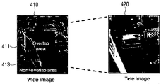
도 4a를 참조하면, 제1 영상(410)은 광각 렌즈로 촬영된 wide 영상일 수 있다. 그리고, 제2 영상(420)은 망원 렌즈로 촬영된 tele 영상일 수 있다. 제1 영상(410)은 제2 영상(420)과 겹치는 오버랩 영역(411)과 겹치지 않는 비오버랩 영역(413)으로 구분될 수 있다. 도 4a의 실시 예에서, 제2 영상(420)은 전 영역이 제1 영상(410)과 겹치는 오버랩 영역으로 도시되었다.
도 4b를 참조하면, 프로세서(120)는 제1 영상의 오버랩 영역(411)과 제2 영상의 오버랩 영역(420)을 이용하여 관계 파라미터 또는 관계 함수를 도출할 수 있다. 구체적으로, 프로세서(120)는 영상의 선명도가 높은 제2 영상의 오버랩 영역(420)을 영상의 선명도가 낮은 제1 영상의 오버랩 영역(411)으로 변환하기 위한 관계 파라미터 또는 관계 함수를 도출할 수 있다.
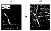
도 4c와 같이, 도출된 관계 함수의 역(inverse)함수를 이용하여, 프로세서(120)는 선명도가 낮은 제1 영상(410)의 오버랩 영역(411) 및 비오버랩 영역(413)을 보정할 수 있다. 즉, 프로세서(120)는 보정된 제1 영상(430)의 선명도가 제2 영상(420)의 선명도에 근접하도록 보정할 수 있다.
*이하에서는 프로세서(120)가 도출된 관계 파라미터(또는 모델)을 이용하여 영상을 보정하는 방법을 수식을 이용하여 설명하기로 한다.
도출된 관계 파라미터를 K, 보정하고자 하는 영상(전체 또는 일부분)을 g, 보정된 영상을 f라고 할 때, 이들의 관계를 수학식 1과 같은 기술할 수 있다. 수학식 1에서 η는 노이즈이고, Kf는 K와 f의 합성곱(convolution)이다.
수학식 1 
도 4의 예를 참고하여 설명하면, 프로세서(120)는 선명도가 높은 제2 영상을 선명도가 낮은 제1 영상(g)로 변환하기 위한 관계 파라미터(K)를 도출할 수 있다. 따라서, 선명도가 낮은 제1 영상(g)와 이를 보정한 영상(f)는 수학식 1과 같은 관계를 가질 수 있다.
수학식 2는 프로세서(120)가 수학식 1에서의 f를 찾기 위한 식을 개념적으로 표현한 것이다.
수학식 2 
프로세서(120)는 보정하고자 하는 영상(g)와 보정한 영상에 관계 파라미터를 적용한 값(Kf)가 최대한 동일하게 되는 f를 찾는 방식으로 영상을 보정할 수 있다. 보정하고자 하는 영상(g)와 보정된 영상에 관계 파라미터를 적용한 값(Kf)의 차이에 관계된 값을 데이터 코스트(Cdata)라고 할 수 있다.
데이터 코스트를 최소화하는 f를 계산하는 것만으로는 적절히 보정된 영상을 찾기 어렵다는 점에서, 프로세서(120)는 제한(constraint)에 해당하는 조정 코스트(Cregularization)를 고려할 수 있다.
본 개시의 일 실시 예에 따르면, 프로세서(120)는 수학식 3을 이용하여 데이터 코스트와 조정 코스트를 최소화하는 보정된 영상(f)을 생성할 수 있다.
수학식 3 
수학식 3의 첫째 항이 데이터 코스트에 해당하며, 둘째 항이 조정 코스트에 해당한다. λ는 조정 코스트의 가중치(weight) 또는 계수(coefficient)에 해당하는 값으로, 프로세서(120)는 최적의 λ를 계산할 수 있다. 프로세서(120)는 조정 코스트를 통해 기울기(gradient)가 적은 f를 찾을 수 있다.
본 개시의 다른 실시 예에 따르면, 프로세서(120)는 수학식 4를 이용하여 데이터 코스트와 조정 코스트를 최소화하는 보정된 영상(f)를 생성할 수 있다.
수학식 4 
수학식 3과 수학식 4을 각각 이용하는 실시 예들 사이의 차이점은 조정 코스트이다. 수학식 3에서는 조정 코스트로 각각의 요소를 제곱한 값을 합하여 루트를 취한 L2 norm의 제곱을 이용하는데 반하여, 수학식 4에서는 조정 코스트로 각각의 요소의 절대 값을 합한 L1 norm의 제곱을 이용한다.
본 개시의 또 다른 실시 예에 따르면, 프로세서(120)는 수학식 5를 이용하여 데이터 코스트와 조정 코스트를 최소화하는 보정된 영상(f)를 생성할 수 있다.
수학식 5 
수학식 5에 따르면, 프로세서(120)는 상술한 바와 같은 두 가지의 조정 코스트 항을 모두 고려할 수 있다. 두 가지 조정 코스트 항들은 서로 트레이드 오프(trade-off) 관계에 있는바, 프로세서(120)는 이들 두 가지 조정 코스트 항을 모두 고려함으로써 최적의 f를 계산할 수 있다. 예를 들어, L2 norm은 해석해(analytical solution)을 계산할 수 있어 계산 효율에서 장점이 있다. L1 norm은 계산 효율은 떨어지나 에러 값에 민감하지 않아 보다 robust하다는 장점이 있다. 따라서, 프로세서(120)는 λ와 γ를 조정함으로써 각각의 영상에 적합한 보정을 수행할 수 있다.
도 5a 및 도 5b는 본 개시의 일 실시 예에 따른 영상 처리 방법이 적용된 실제 영상을 도시한 도면이다. 도 5a를 참조하면, wide 영상인 제1 영상(510) 및 tele 영상인 제2 영상(520)이 도시되어 있다. 그리고, 제1 영상의 오버랩 영역(511)과 제2 영상(520)의 촬영 대상이 동일하다.
제1 영상(510)은 wide 영상이기 때문에 tele 영상인 제2 영상(520)에 비하여 흐릿하게(blur) 촬영되어 있다. 프로세서(120)는 제2 영상(520)의 오버랩 영역과 제1 영상의 오버랩 영역(511)을 이용하여 블러(blur)에 관계된 함수인 PSF(point spread function)의 파라미터를 도출할 수 있다. 구체적으로, 프로세서(120)는 제2 영상(520)에 PSF를 적용하여 제1 영상의 오버랩 영역(511)을 생성할 수 있는 PSF의 파라미터를 도출할 수 있다. 그리고, 프로세서(120)는 도출된 파라미터를 갖는 PSF의 역함수를 제1 영상(510)에 적용하여 보정된 이미지(530)를 생성할 수 있다. 도 5b에서는 보정 효과를 명확히 도시하기 위하여 오버랩 영역(511)에 대해서만 도시하였으나, 프로세서(120)는 오버랩 영역간의 관계를 통해 도출된 PSF의 역함수를 이용하여 제1 영상(510)의 비오버랩 영역을 보정할 수 있음은 물론이다.
도 6a 및 도 6b는 본 개시의 일 실시 예에 따른 관계 파라미터 도출을 설명하기 위한 도면이다. 도 6a 및 도 6b에서는 블러(blur) 처리를 위한 PSF 함수의 파라미터를 도출하는 실시 예를 도시하였다. 예를 들어, PSF 함수의 파라미터는 가우시안 블러 함수의 분산(variance) 값일 수 있다.
종래의 영상 처리 장치는 어떠한 영상인지에 관계없이 기설정된 파라미터를 갖는 PSF를 적용하여 보정을 진행하였다. 하지만, 본 개시의 일 실시 예에 따른 영상 처리 장치(100)는 복수의 영상들의 오버랩 영역간의 관계를 도출하여 해당 영상에 적합한 PSF 파라미터를 도출할 수 있다.
도 6a를 참조하면, 종래의 영상 처리 장치는 어떠한 영상을 처리하는지에 관계 없이 0.7 또는 2.0과 같은 기설정된 파라미터를 갖는 PSF를 이용하여 보정을 진행하였다. 하지만, 본 개시의 일 실시 예에 따른 영상 처리 장치(100)는 복수의 영상의 오버랩 영역 간의 관계를 통해 최적의 파라미터가 1.619임을 도출할 수 있다.
종래의 영상 처리 장치는 도 6a에 적합한 파라미터인 1.6를 갖도록 조정하더라도, 도 6b와 같이 영상이 변경되면 적합한 보정을 수행할 수 없게 된다. 이에 반해, 본 개시의 일 실시 예에 따른 영상 처리 장치(100)는 도 6b 영상들의 오버랩 영역간의 관계를 이용하여 최적의 파라미터인 1.18을 도출할 수 있다. 따라서, 본 개시의 일 실시 예에 따른 영상 처리 장치(100)와 같이 복수의 영상의 오버랩 영역 간의 관계를 도출하여야만 보다 정밀하고 각 영상에 적합한 보정이 수행될 수 있다. 그리고, 본 개시의 일 실시 예에 따른 영상 처리 장치(100)는 이렇게 영상에 적합하게 도출한 관계 파라미터를 이용하여 오버랩 영역 뿐만 아니라 비오버랩 영역에 대한 보정을 수행할 수 있다.
이하에서는 제1 영상과 제2 영상이 촬영된 조건의 차이에 따라 제1 영상 및 제2 영상 중 적어도 하나를 보정하는 다양한 실시 예를 설명하기로 한다.
도 7a은 영상 처리 장치(100)가 tele 영상을 이용하여 wide 영상의 선명도를 향상시키는 실시 예를 도시한 도면이다. 설명의 편의를 위하여 tele 영상과 wide 영상으로 도시하였으나, 영상 입력부(110)에 입력된 2개의 영상의 화각(FoV) 차이가 존재하면 되기 때문에, 프로세서(120)는 tele 영상을 이용하여 normal 영상의 선명도를 향상시킬 수도 있다.
예를 들어, tele 영상과 wide 영상은 각각 망원 렌즈와 광각 렌즈를 구비한 촬영 소자로부터 촬영될 수 있다. 이러한 경우, 영상 처리 장치(100)는 듀얼 카메라를 구비한 스마트폰으로 구현될 수 있다. 다른 예로, wide 영상은 고해상도의 카메라로 촬영될 수 있고, tele 영상은 작은 크기의 화질 개선용 저해상도 카메라로 촬영될 수 있다. 이러한 경우, 영상 처리 장치(100)는 듀얼 카메라가 아닌 화질 개선용 보조 렌즈를 포함하는 단일 카메라를 구비한 스마트폰으로 구현될 수도 있다.
프로세서(120)는 입력된 tele 영상(710)과 wide 영상(720)을 정합하여 각각의 영상의 오버랩 영역을 검출할 수 있다. 도 7a를 참조하면, tele 영상(710)의 전 영역은 wide 영상(720)과 겹치는 오버랩 영역이다. 그리고, wide 영상(720)은 tele 영상(710)과 겹치는 오버랩 영역(721) 및 겹치지 않는 비오버랩 영역(723)을 포함한다.
프로세서(120)는 오버랩 영역들(710, 721) 사이의 관계 파라미터를 도출할 수 있다. 예를 들어, 프로세서(120)는 tele 영상의 오버랩 영역(710)에 블러 함수를 적용하여 wide 영상의 오버랩 영역(721)을 생성할 수 있는 블러 파라미터를 도출할 수 있다.
그리고, 프로세서(120)는 도출된 블러 파라미터를 이용하여 디블러(deblur) 함수 모델을 결정할 수 있다. 프로세서(120)는 디블러 함수를 wide 영상(720)에 적용하여 wide 영상(720)의 선명도를 보정할 수 있다.
도 7b의 실시 예를 참조하면, 프로세서(120)는 wide 영상(720)의 비오버랩 영역(723)에 대해서만 보정을 수행할 수 있다. 그리고, 프로세서(120)는 오버랩 영역의 영상으로 tele 영상(710)을 이용할 수 있다. 왜냐하면, 도출된 관계 파라미터로 프로세서(120)가 wide 영상(720)의 오버랩 영역(721)을 보정한 최상의 결과가 tele 영상(710)이기 때문이다. 즉, 프로세서(120)는 wide 영상의 비오버랩 영역(723)을 보정하고, 보정된 wide 영상의 비오버랩 영역(723)과 tele 영상의 오버랩 영역(710)을 합성하여 출력할 수 있다.
구체적으로, 도 7a에서 도출된 블러 파라미터를 이용하여, 프로세서(120)는 wide 영상의 비오버랩 영역(723)을 보정할 수 있다. 그리고, 프로세서(120)는 tele 영상의 오버랩 영역(710)에 시차 보상, 밝기 보상 등을 수행할 수 있다. 프로세서(120)는 보상된 tele 영상의 오버랩 영역(711)과 보정된 wide 영상의 비오버랩 영역(723)을 합성할 수 있다. 프로세서(120)는 경계 처리와 같은 추가적인 영상 처리를 수행하여 최종 합성된 영상(740)을 출력할 수 있다.
도 8은 영상 처리 장치(100)가 감도 차이에 의한 노이즈 특성을 모델링하여 노이즈가 개선된 wide 영상을 생성하는 실시 예를 도시한 도면이다. 도 8의 실시 예에서 제1 영상(810)은 고감도 tele 카메라가 촬영한 영상이며, 제2 영상(820)은 wide 또는 normal 영상이다.
프로세서(120)는 제1 영상(810) 및 제2 영상(820)을 정합하여 각 영상의 오버랩 영역을 도출할 수 있다. 제1 영상(810)의 전 영역은 제2 영상(820)과 겹치는 오버랩 영역이다. 그리고, 제2 영상(820)은 제1 영상(810)과 겹치는 오버랩 영역(821) 및 겹치지 않는 비오버랩 영역(823)을 포함할 수 있다.
프로세서(120)는 오버랩 영역들(810, 821) 사이의 관계 파라미터를 도출할 수 있다. 예를 들어, 프로세서(120)는 tele 영상의 오버랩 영역(810)에 노이즈 함수를 적용하여 wide 영상의 오버랩 영역(821)을 생성할 수 있는 노이즈 파라미터를 도출할 수 있다.
그리고, 프로세서(120)는 도출된 노이즈 파라미터를 이용하여 디노이즈(denoise) 함수 모델을 결정할 수 있다. 프로세서(120)는 디노이즈 함수를 wide 영상(820)에 적용하여 wide 영상(820)의 노이즈를 저감할 수 있다.
도 9는 영상 처리 장치(100)가 감도 차이에 의한 노이즈 특성을 모델링하여 노이즈가 개선된 영상을 생성하는 실시 예를 도시한 도면이다. 도 8의 실시 예와의 차이점은 도 9에 도시된 실시 예가 화각(FoV)이 동일한 영상 간에 적용될 수 있다는 점이다. 도 9의 실시 예에서 제1 영상(910)은 고감도 영상이며, 제2 영상(920)은 저감도 영상이다.
프로세서(120)는 제1 영상(910) 및 제2 영상(920)을 정합하여 각 영상의 오버랩 영역(911, 921)을 도출할 수 있다. 그리고, 프로세서(120)는 오버랩 영역들(911, 921) 사이의 관계 파라미터인 노이즈 파라미터를 도출할 수 있다. 구체적으로, 프로세서(120)는 제1 영상의 오버랩 영역(911)에 노이즈 함수를 적용하여 제2 영상의 오버랩 영역(921)을 생성할 수 있는 노이즈 파라미터를 도출할 수 있다.
그리고, 프로세서(120)는 도출된 노이즈 파라미터를 이용하여 디노이즈(denoise) 함수 모델을 결정할 수 있다. 프로세서(120)는 디노이즈 함수를 저감도 영상인 제2 영상(920)에 적용하여 노이즈가 개선된 제2 영상(930)을 생성할 수 있다. 프로세서(120)는 노이즈가 개선된 제2 영상(930)과 제1 영상(910)을 합성할 수 있다. 그리고, 프로세서(120)는 경계 처리와 같은 추가적인 영상 처리를 수행하여 최종 합성된 영상(940)을 출력할 수 있다.
도 9의 실시 예에서는 보정된 제2 영상 전체(930)와 제1 영상의 비오버랩 영역을 합성하는 것으로 도시되었으나, 제1 영상 전체(910)와 보정된 제2 영상(930)의 비오버랩 영역을 합성하는 것도 가능하다.
도 10은 영상 처리 장치(100)가 wide 영상을 이용하여 tele 영상의 노이즈를 저감하는 실시 예를 도시한 도면이다. 설명의 편의를 위하여 tele 영상과 wide 영상으로 도시하였으나, 영상 입력부(110)에 입력된 2개의 영상의 화각(FoV) 차이가 존재하면 되기 때문에, 프로세서(120)는 normal 영상을 이용하여 tele 영상의 노이즈를 줄일 수 있다.
도 10의 실시 예에서 제1 영상(1010)은 wide 영상이며, 제2 영상(1020)은 tele 영상이다. wide 영상은 밝고 노이즈가 적은 특성을 갖고, tele 영상은 고해상도이지만 어둡고 노이즈가 많은 특성을 갖는다.
프로세서(120)는 제1 영상(1010) 및 제2 영상(1020)을 정합하여 각 영상의 오버랩 영역(1011, 1021)을 도출할 수 있다. 그리고, 프로세서(120)는 오버랩 영역들(1011, 1021) 사이의 관계 파라미터인 노이즈 파라미터를 도출할 수 있다. 구체적으로, 프로세서(120)는 제1 영상의 오버랩 영역(1011)에 노이즈 함수를 적용하여 제2 영상의 오버랩 영역(1021)을 생성할 수 있는 노이즈 파라미터를 도출할 수 있다. 그리고, 프로세서(120)는 도출된 노이즈 파라미터를 이용하여 디노이즈(denoise) 함수 모델을 결정할 수 있다. 프로세서(120)는 디노이즈 함수를 tele 영상인 제2 영상(1020)에 적용하여 노이즈가 개선된 제2 영상(1030)을 생성할 수 있다.
도 11은 영상 처리 장치(100)가 노출 시간이 다른 영상을 이용하여 모션 블러를 제거하는 실시 예들 도시한 도면이다. 도 11의 실시 예에서, 제1 영상(1110)은 셔터 속도가 짧은 촬영 소자를 통해 촬영되어 노출 시간이 짧은 영상이고, 제2 영상(1120)은 노출 시간이 제1 영상(1110)에 비해 긴 영상이다.
노출 시간이 짧은 제1 영상(1110)은 모션 블러가 적은데 반하여 노이즈가 많고, 노출 시간이 긴 제2 영상(1120)은 노이즈가 적은데 반하여 모션 블러가 많다.
프로세서(120)는 제1 영상(1110) 및 제2 영상(1120)을 정합하여 각 영상의 오버랩 영역을 도출할 수 있다. 제1 영상(1110)의 전 영역은 제2 영상(1120)과 겹치는 오버랩 영역이다. 그리고, 제2 영상(1120)은 제1 영상(1110)과 겹치는 오버랩 영역(1121) 및 겹치지 않는 비오버랩 영역을 포함할 수 있다.
프로세서(120)는 오버랩 영역들(1110, 1121) 사이의 관계 파라미터를 도출할 수 있다. 구체적으로, 프로세서(120)는 제1 영상(1110)에 모션 블러 함수를 적용하여 제2 영상의 오버랩 영역(1121)을 생성할 수 있는 모션 블러 파라미터를 도출할 수 있다. 그리고, 프로세서(120)는 도출된 모션 블러 파라미터를 이용하여 디블러 함수 모델을 결정할 수 있다. 프로세서(120)는 디블러 함수를 제2 영상(1120)에 적용하여 모션 블러가 개선된 제1 영상(1230)을 생성할 수 있다.
도 11에서는 영상 처리 장치(100)가 노출 시간이 긴 제2 영상(120)의 모션 블러만을 제거하는 실시 예를 도시하였으나, 노출 시간이 짧은 제1 영상(1110)의 노이즈를 제거할 수도 있다. 또한, 영상 처리 장치(100)는 제1 영상(1110)과 제2 영상(1120)에서 각각 노이즈와 모션 블러를 동시에 제거할 수도 있다.
상술한 바와 같은 다양한 실시 예에 따르면, 영상 처리 장치(100)는 복수의 영상의 오버랩 영역 사이의 관계 모델을 이용하여 비오버랩 영역의 화질을 개선할 수 있다. 예를 들어, 화각(FoV)이 상이한 복수의 영상을 이용할 경우, 영상 처리 장치(100)는 넓은 화각을 가지면서도 해상도가 높은 영상을 생성할 수 있다.
도 12는 본 개시의 일 실시 예에 따른 영상 처리 장치(100)의 영상 처리 방법을 설명하기 위한 흐름도이다. 도 12를 참조하면, 영상 처리 장치(100)는 제1 영상 및 제2 영상을 수신할 수 있다(S1210). 제1 영상 및 제2 영상은 서로 오버랩되는 영역을 갖도록 촬영된 영상일 수 있다. 또한, 제1 영상 및 제2 영상은 상이한 광학 특성 조건에서 촬영된 영상일 수 있다. 예를 들어, 제1 영상 및 제2 영상은 동일한 객체에 대하여 서로 다른 초점 거리로 촬영된 영상일 수 있다. 영상 처리 장치(100)는 제1 영상 및 제2 영상을 자체적으로 촬영할 수 있으며, 외부 장치에서 촬영된 영상을 수신할 수도 있다.
그리고, 영상 처리 장치(100)는 제1 영상 및 제2 영상을 정합하여 각각의 영상의 오버랩 영역을 검출할 수 있다(S1220). 그리고, 영상 처리 장치(100)는 제1 영상의 오버랩 영역과 제2 영상의 오버랩 영역을 이용하여 관계 파라미터를 도출할 수 있다(S1230). 도출된 오버랩 영역 간의 관계 파라미터를 이용하여, 영상 처리 장치(100)는 제1 영상 및 제2 영상 중 적어도 하나의 영상을 보정할 수 있다(S1240).
영상 처리 장치(100)는 제1 영상 및 제2 영상의 차이점을 이용하여 도출할 관계 파라미터를 결정할 수 있다. 관계 파라미터는 제1 영상 및 제2 영상 중 하나의 오버랩 영역 영상을 나머지 영상의 오버랩 영역 영상으로 변환하기 위한 파라미터이다. 예를 들어, 관계 파라미터는 블러 파라미터, 노이즈 파라미터, 모션 블러 파라미터, 채도 파라미터, 대조비 파라미터, 다이내믹 레인지 파라미터 중 적어도 하나일 수 있다. 그리고, 영상 처리 장치(100)는 도출된 관계 파라미터가 무엇인지에 따라 제1 영상 및 제2 영상 중 어느 영상을 보정할 것인지 결정할 수 있다.
도 13은 본 개시의 일 실시 예에 따른 영상 처리 장치(100)의 영상 처리 방법을 설명하기 위한 흐름도이다. S1310 내지 S1330 단계는 S1210 내지 S1230 단계와 각각 대응되는바 중복 설명을 생략하기로 한다.
영상 처리 장치(100)는 도출된 관계 파라미터를 이용하여 제1 영상 및 제2 영상 중 적어도 하나의 영상의 비오버랩 영역을 보정할 수 있다(S1340). 그리고, 영상 처리 장치(100)는 보정된 비오버랩 영역과 제1 영상 및 제2 영상 중 하나의 오버랩 영역을 합성하여 출력할 수 있다(S1350). 이에 따라 영상 처리 장치(100)는 넓은 화각을 가지면서도 화질이 개선된 영상을 생성할 수 있다.
다른 실시 예에서, 영상 처리 장치(100)는 합성 과정 없이 제1 영상 및 제2 영상 중 하나의 영상에 대해서만 보정하여 출력할 수도 있다.
그 밖에, 구체적인 관계 파라미터를 이용하는 영상 처리 장치(100)의 영상 처리 방법에 대해서는 상술한 영상 처리 장치(100)의 설명과 중복되는바 생략하기로 한다.
상기에서 설명된 방법들은 다양한 컴퓨터 수단을 통하여 수행될 수 있는 프로그램 명령 형태로 구현되어 컴퓨터 판독 가능 매체에 기록될 수 있다. 상기 컴퓨터 판독 가능 매체는 프로그램 명령, 데이터 파일, 데이터 구조 등을 단독으로 또는 조합하여 포함할 수 있다. 상기 매체에 기록되는 프로그램 명령은 본 발명을 위하여 특별히 설계되고 구성된 것들이거나 컴퓨터 소프트웨어 당업자에게 공지되어 사용 가능한 것일 수도 있다. 컴퓨터 판독 가능 기록 매체의 예에는 하드 디스크, 플로피 디스크 및 자기 테이프와 같은 자기 매체(magnetic media), CD-ROM, DVD와 같은 광 기록 매체(optical media), 플롭티컬 디스크(floptical disk)와 같은 자기-광 매체(magneto-optical media), 및 롬(ROM), 램(RAM), 플래시 메모리 등과 같은 프로그램 명령을 저장하고 수행하도록 특별히 구성된 하드웨어 장치가 포함된다. 프로그램 명령의 예에는 컴파일러에 의해 만들어지는 것과 같은 기계어 코드뿐만 아니라 인터프리터 등을 사용해서 컴퓨터에 의해서 실행될 수 있는 고급 언어 코드를 포함한다. 상기의 하드웨어 장치는 본 발명의 동작을 수행하기 위해 하나 이상의 소프트웨어 모듈로서 작동하도록 구성될 수 있으며, 그 역도 마찬가지이다.
이상과 같이 본 개시는 비록 한정된 실시 예와 도면에 의해 설명되었으나, 본 개시는 상기의 실시 예에 한정되는 것은 아니며, 본 개시가 속하는 분야에서 통상의 지식을 가진 자라면 이러한 기재로부터 다양한 수정 및 변형이 가능하다. 그러므로, 본 개시의 범위는 설명된 실시 예에 국한되어 정해져서는 아니 되며, 후술하는 특허청구범위뿐 아니라 이 특허청구범위와 균등한 것들에 의해 정해져야 한다.
Claims (15)
- 영상 처리 장치에 있어서,제1 영상 및 제2 영상을 수신하는 영상 입력부; 및상기 제1 영상과 상기 제2 영상 각각의 오버랩 영역을 검출하고, 상기 제1 영상의 오버랩 영역과 상기 제2 영상의 오버랩 영역을 이용하여 관계 파라미터를 도출하고, 상기 도출된 관계 파라미터를 이용하여 상기 제1 영상 및 상기 제2 영상 중 적어도 하나의 영상을 보정하는 프로세서;를 포함하는 영상 처리 장치.
- 제1항에 있어서,상기 프로세서는,상기 제1 영상 및 상기 제2 영상의 차이점을 이용하여 도출할 관계 파라미터를 결정하고,상기 관계 파라미터는, 상기 제1 영상 및 상기 제2 영상 중 하나의 오버랩 영역을 나머지 영상의 오버랩 영역으로 변환하기 위한 파라미터인 영상 처리 장치.
- 제1항에 있어서,상기 프로세서는,상기 도출된 관계 파라미터를 이용하여 상기 제1 영상 및 상기 제2 영상 중 적어도 하나의 영상의 비오버랩 영역을 보정하고, 상기 보정된 비오버랩 영역과 상기 제1 영상 및 상기 제2 영상 중 하나의 오버랩 영역을 합성하여 출력하는 영상 처리 장치.
- 제1항에 있어서,상기 관계 파라미터는,블러 파라미터, 노이즈 파라미터, 모션 블러 파라미터, 채도 파라미터, 대조비 파라미터, 다이내믹 레인지 파라미터 중 적어도 하나인 영상 처리 장치.
- 제1항에 있어서,상기 프로세서는,상기 제1 영상의 화각(FoV)이 상기 제2 영상의 화각보다 크면, 상기 제1 영상의 오버랩 영역과 상기 제2 영상의 오버랩 영역 사이의 블러 파라미터를 도출하고, 상기 도출된 블러 파라미터를 이용하여 상기 제1 영상의 비오버랩 영역을 보정하는 영상 처리 장치.
- 제1항에 있어서,상기 프로세서는,상기 제1 영상의 화각(FoV)이 상기 제2 영상의 화각보다 크면, 상기 제1 영상의 오버랩 영역과 상기 제2 영상의 오버랩 영역 사이의 노이즈 파라미터를 도출하고, 상기 도출된 노이즈 파라미터를 이용하여 상기 제2 영상의 비오버랩 영역을 보정하는 영상 처리 장치.
- 제1항에 있어서,상기 프로세서는,상기 제1 영상의 감도가 상기 제2 영상의 감도보다 높으면, 상기 제1 영상의 오버랩 영역과 상기 제2 영상의 오버랩 영역 사이의 노이즈 파라미터를 도출하고, 상기 도출된 노이즈 파라미터를 이용하여 상기 제2 영상의 비오버랩 영역을 보정하는 영상 처리 장치.
- 제1항에 있어서,상기 프로세서는,상기 제1 영상의 노출 시간이 상기 제2 영상의 노출 시간보다 길면, 상기 제1 영상의 오버랩 영역과 상기 제2 영상의 오버랩 영역 사이의 모션 블러 파라미터를 도출하고, 상기 도출된 모션 블러 파라미터를 이용하여 상기 제1 영상의 비오버랩 영역을 보정하는 영상 처리 장치.
- 제1항에 있어서,상기 프로세서는,상기 제1 영상의 노출 시간이 상기 제2 영상의 노출 시간보다 길면, 상기 제1 영상의 오버랩 영역과 상기 제2 영상의 오버랩 영역 사이의 노이즈 파라미터를 도출하고, 상기 도출된 노이즈 파라미터를 이용하여 상기 제2 영상의 비오버랩 영역을 보정하는 영상 처리 장치.
- 제1항에 있어서,상기 프로세서는,상기 도출된 관계 파라미터에 보정 결과 영상을 적용한 영상과 보정할 영상의 차이에 관련된 값 및 상기 보정 결과 영상의 기울기에 관련된 값으로 구성된 코스트를 최소화하는 상기 보정 결과 영상을 결정하여, 상기 제1 영상 및 상기 제2 영상 중 적어도 하나의 영상을 보정하는 영상 처리 장치.
- 영상 처리 장치의 영상 처리 방법에 있어서,제1 영상 및 제2 영상을 수신하는 단계;상기 제1 영상 및 상기 제2 영상 각각의 오버랩 영역을 검출하는 단계;상기 제1 영상의 오버랩 영역과 상기 제2 영상의 오버랩 영역을 이용하여 관계 파라미터를 도출하는 단계; 및상기 도출된 관계 파라미터를 이용하여 상기 제1 영상 및 상기 제2 영상 중 적어도 하나의 영상을 보정하는 단계;를 포함하는 영상 처리 방법.
- 제11항에 있어서,상기 제1 영상 및 상기 제2 영상의 차이점을 이용하여 도출할 관계 파라미터를 결정하는 단계;를 더 포함하고,상기 관계 파라미터는, 상기 제1 영상 및 상기 제2 영상 중 하나의 오버랩 영역을 나머지 영상의 오버랩 영역으로 변환하기 위한 파라미터인 영상 처리 방법.
- 제11항에 있어서,상기 보정하는 단계는,상기 도출된 관계 파라미터를 이용하여 상기 제1 영상 및 상기 제2 영상 중 적어도 하나의 영상의 비오버랩 영역을 보정하는 단계; 및상기 보정된 비오버랩 영역과 상기 제1 영상 및 상기 제2 영상 중 하나의 오버랩 영역을 합성하여 출력하는 단계;를 포함하는 영상 처리 방법.
- 제11항에 있어서,상기 관계 파라미터는,블러 파라미터, 노이즈 파라미터, 모션 블러 파라미터, 채도 파라미터, 대조비 파라미터, 다이내믹 레인지 파라미터 중 적어도 하나인 영상 처리 방법.
- 제11항에 있어서,상기 도출하는 단계는,상기 제1 영상의 화각(FoV)이 상기 제2 영상의 화각보다 크면, 상기 제1 영상의 오버랩 영역과 상기 제2 영상의 오버랩 영역 사이의 블러 파라미터를 도출하고,상기 보정하는 단계는,상기 도출된 블러 파라미터를 이용하여 상기 제1 영상의 비오버랩 영역을 보정하는 영상 처리 방법.
Applications Claiming Priority (2)
| Application Number | Priority Date | Filing Date | Title |
|---|---|---|---|
| KR1020160068848A KR20170136828A (ko) | 2016-06-02 | 2016-06-02 | 영상 처리 장치, 그의 영상 처리 방법 및 비일시적 컴퓨터 판독가능 기록매체 |
| KR10-2016-0068848 | 2016-06-02 |
Publications (1)
| Publication Number | Publication Date |
|---|---|
| WO2017209509A1 true WO2017209509A1 (ko) | 2017-12-07 |
Family
ID=60478682
Family Applications (1)
| Application Number | Title | Priority Date | Filing Date |
|---|---|---|---|
| PCT/KR2017/005684 Ceased WO2017209509A1 (ko) | 2016-06-02 | 2017-05-31 | 영상 처리 장치, 그의 영상 처리 방법 및 비일시적 컴퓨터 판독가능 기록매체 |
Country Status (2)
| Country | Link |
|---|---|
| KR (1) | KR20170136828A (ko) |
| WO (1) | WO2017209509A1 (ko) |
Cited By (1)
| Publication number | Priority date | Publication date | Assignee | Title |
|---|---|---|---|---|
| US20220394181A1 (en) * | 2021-06-03 | 2022-12-08 | Samsung Electronics Co., Ltd. | Method and electronic device for rectifying an image |
Families Citing this family (2)
| Publication number | Priority date | Publication date | Assignee | Title |
|---|---|---|---|---|
| WO2019004725A1 (ko) | 2017-06-27 | 2019-01-03 | 주식회사 엘지화학 | 장식 부재 및 이의 제조방법 |
| KR102581236B1 (ko) * | 2022-02-16 | 2023-09-22 | 주식회사 비지트 | 파노라믹 영상 블렌딩 방법 및 장치 |
Citations (5)
| Publication number | Priority date | Publication date | Assignee | Title |
|---|---|---|---|---|
| US20060003328A1 (en) * | 2002-03-25 | 2006-01-05 | Grossberg Michael D | Method and system for enhancing data quality |
| US20080218611A1 (en) * | 2007-03-09 | 2008-09-11 | Parulski Kenneth A | Method and apparatus for operating a dual lens camera to augment an image |
| WO2011029203A1 (en) * | 2009-09-14 | 2011-03-17 | Viion Systems Inc. | Saccadic dual-resolution video analytics camera |
| US20150103197A1 (en) * | 2013-10-11 | 2015-04-16 | Telefonaktiebolaget L M Ericsson (Publ) | Technique for view synthesis |
| US20150271483A1 (en) * | 2014-03-20 | 2015-09-24 | Gopro, Inc. | Target-Less Auto-Alignment Of Image Sensors In A Multi-Camera System |
-
2016
- 2016-06-02 KR KR1020160068848A patent/KR20170136828A/ko not_active Withdrawn
-
2017
- 2017-05-31 WO PCT/KR2017/005684 patent/WO2017209509A1/ko not_active Ceased
Patent Citations (5)
| Publication number | Priority date | Publication date | Assignee | Title |
|---|---|---|---|---|
| US20060003328A1 (en) * | 2002-03-25 | 2006-01-05 | Grossberg Michael D | Method and system for enhancing data quality |
| US20080218611A1 (en) * | 2007-03-09 | 2008-09-11 | Parulski Kenneth A | Method and apparatus for operating a dual lens camera to augment an image |
| WO2011029203A1 (en) * | 2009-09-14 | 2011-03-17 | Viion Systems Inc. | Saccadic dual-resolution video analytics camera |
| US20150103197A1 (en) * | 2013-10-11 | 2015-04-16 | Telefonaktiebolaget L M Ericsson (Publ) | Technique for view synthesis |
| US20150271483A1 (en) * | 2014-03-20 | 2015-09-24 | Gopro, Inc. | Target-Less Auto-Alignment Of Image Sensors In A Multi-Camera System |
Cited By (3)
| Publication number | Priority date | Publication date | Assignee | Title |
|---|---|---|---|---|
| US20220394181A1 (en) * | 2021-06-03 | 2022-12-08 | Samsung Electronics Co., Ltd. | Method and electronic device for rectifying an image |
| US11750928B2 (en) * | 2021-06-03 | 2023-09-05 | Samsung Electronics Co., Ltd. | Method and electronic device for rectifying an image |
| EP4241234A4 (en) * | 2021-06-03 | 2024-05-01 | Samsung Electronics Co., Ltd. | Method and electronic device for rectifying an image |
Also Published As
| Publication number | Publication date |
|---|---|
| KR20170136828A (ko) | 2017-12-12 |
Similar Documents
| Publication | Publication Date | Title |
|---|---|---|
| WO2018147581A1 (en) | Method and apparatus for selecting capture configuration based on scene analysis | |
| JP6663040B2 (ja) | 奥行き情報取得方法および装置、ならびに画像取得デバイス | |
| WO2018053906A1 (zh) | 一种基于双摄像头的拍摄方法、装置和移动终端 | |
| WO2017171465A1 (en) | Electronic device and operating method thereof | |
| WO2017090848A1 (en) | Photographing device and operating method of the same | |
| EP3320676A1 (en) | Image capturing apparatus and method of operating the same | |
| WO2016096167A1 (en) | Selective high frame rate video capturing in imaging sensor subarea | |
| WO2021101162A1 (ko) | 딥 화이트-밸런싱 편집을 위한 방법 및 장치 | |
| US10270977B2 (en) | Imaging apparatus and a method of tracking a subject in the imaging apparatus | |
| WO2015122604A1 (en) | Solid-state image sensor, electronic device, and auto focusing method | |
| WO2016048020A1 (ko) | 3d 파노라마 이미지 생성을 위한 영상 생성 장치 및 방법 | |
| WO2020076128A1 (en) | Method and electronic device for switching between first lens and second lens | |
| WO2017012372A1 (zh) | 用于终端的拍照控制方法、装置和终端 | |
| CN104780313A (zh) | 一种图像处理的方法及移动终端 | |
| WO2018040269A1 (zh) | 一种图像处理方法及终端 | |
| WO2021118111A1 (ko) | 이미지 처리 장치 및 이미지 처리 방법 | |
| WO2013009099A2 (ko) | 블러 처리 장치 및 방법 | |
| WO2017209509A1 (ko) | 영상 처리 장치, 그의 영상 처리 방법 및 비일시적 컴퓨터 판독가능 기록매체 | |
| US10547785B2 (en) | Photographing method including image registration based on reference image, shake information, and a motion vector table | |
| KR102592745B1 (ko) | 자세 추정 장치, 자세 추정 방법 및 기록 매체에 저장된 컴퓨터 프로그램 | |
| CN107211098A (zh) | 针对顺序子图像的基于噪声电平的曝光时间控制 | |
| WO2013047954A1 (ko) | 배경의 특징점으로부터 획득한 전역 움직임을 이용하여 영상을 안정화하는 영상 촬영 장치 및 방법 | |
| WO2018110889A1 (ko) | 영상의 화이트 밸런스를 보정하는 방법 및 전자 장치 | |
| WO2023219466A1 (en) | Methods and systems for enhancing low light frame in a multi camera system | |
| Sindelar et al. | Space-variant image deblurring on smartphones using inertial sensors |
Legal Events
| Date | Code | Title | Description |
|---|---|---|---|
| NENP | Non-entry into the national phase |
Ref country code: DE |
|
| 121 | Ep: the epo has been informed by wipo that ep was designated in this application |
Ref document number: 17807002 Country of ref document: EP Kind code of ref document: A1 |
|
| 122 | Ep: pct application non-entry in european phase |
Ref document number: 17807002 Country of ref document: EP Kind code of ref document: A1 |