WO2017212713A1 - 回転機械 - Google Patents
回転機械 Download PDFInfo
- Publication number
- WO2017212713A1 WO2017212713A1 PCT/JP2017/008780 JP2017008780W WO2017212713A1 WO 2017212713 A1 WO2017212713 A1 WO 2017212713A1 JP 2017008780 W JP2017008780 W JP 2017008780W WO 2017212713 A1 WO2017212713 A1 WO 2017212713A1
- Authority
- WO
- WIPO (PCT)
- Prior art keywords
- flow path
- cooling gas
- rotating shaft
- axial
- rotating machine
- Prior art date
- Legal status (The legal status is an assumption and is not a legal conclusion. Google has not performed a legal analysis and makes no representation as to the accuracy of the status listed.)
- Ceased
Links
Images




Classifications
-
- F—MECHANICAL ENGINEERING; LIGHTING; HEATING; WEAPONS; BLASTING
- F25—REFRIGERATION OR COOLING; COMBINED HEATING AND REFRIGERATION SYSTEMS; HEAT PUMP SYSTEMS; MANUFACTURE OR STORAGE OF ICE; LIQUEFACTION SOLIDIFICATION OF GASES
- F25B—REFRIGERATION MACHINES, PLANTS OR SYSTEMS; COMBINED HEATING AND REFRIGERATION SYSTEMS; HEAT PUMP SYSTEMS
- F25B49/00—Arrangement or mounting of control or safety devices
- F25B49/02—Arrangement or mounting of control or safety devices for compression type machines, plants or systems
- F25B49/022—Compressor control arrangements
-
- F—MECHANICAL ENGINEERING; LIGHTING; HEATING; WEAPONS; BLASTING
- F04—POSITIVE - DISPLACEMENT MACHINES FOR LIQUIDS; PUMPS FOR LIQUIDS OR ELASTIC FLUIDS
- F04D—NON-POSITIVE-DISPLACEMENT PUMPS
- F04D29/00—Details, component parts, or accessories
- F04D29/05—Shafts or bearings, or assemblies thereof, specially adapted for elastic fluid pumps
- F04D29/051—Axial thrust balancing
-
- F—MECHANICAL ENGINEERING; LIGHTING; HEATING; WEAPONS; BLASTING
- F04—POSITIVE - DISPLACEMENT MACHINES FOR LIQUIDS; PUMPS FOR LIQUIDS OR ELASTIC FLUIDS
- F04D—NON-POSITIVE-DISPLACEMENT PUMPS
- F04D29/00—Details, component parts, or accessories
- F04D29/58—Cooling; Heating; Diminishing heat transfer
- F04D29/5806—Cooling the drive system
-
- F—MECHANICAL ENGINEERING; LIGHTING; HEATING; WEAPONS; BLASTING
- F04—POSITIVE - DISPLACEMENT MACHINES FOR LIQUIDS; PUMPS FOR LIQUIDS OR ELASTIC FLUIDS
- F04D—NON-POSITIVE-DISPLACEMENT PUMPS
- F04D29/00—Details, component parts, or accessories
- F04D29/58—Cooling; Heating; Diminishing heat transfer
- F04D29/582—Cooling; Heating; Diminishing heat transfer specially adapted for elastic fluid pumps
- F04D29/584—Cooling; Heating; Diminishing heat transfer specially adapted for elastic fluid pumps cooling or heating the machine
-
- F—MECHANICAL ENGINEERING; LIGHTING; HEATING; WEAPONS; BLASTING
- F16—ENGINEERING ELEMENTS AND UNITS; GENERAL MEASURES FOR PRODUCING AND MAINTAINING EFFECTIVE FUNCTIONING OF MACHINES OR INSTALLATIONS; THERMAL INSULATION IN GENERAL
- F16C—SHAFTS; FLEXIBLE SHAFTS; ELEMENTS OR CRANKSHAFT MECHANISMS; ROTARY BODIES OTHER THAN GEARING ELEMENTS; BEARINGS
- F16C32/00—Bearings not otherwise provided for
- F16C32/04—Bearings not otherwise provided for using magnetic or electric supporting means
- F16C32/0406—Magnetic bearings
- F16C32/044—Active magnetic bearings
- F16C32/047—Details of housings; Mounting of active magnetic bearings
-
- F—MECHANICAL ENGINEERING; LIGHTING; HEATING; WEAPONS; BLASTING
- F16—ENGINEERING ELEMENTS AND UNITS; GENERAL MEASURES FOR PRODUCING AND MAINTAINING EFFECTIVE FUNCTIONING OF MACHINES OR INSTALLATIONS; THERMAL INSULATION IN GENERAL
- F16C—SHAFTS; FLEXIBLE SHAFTS; ELEMENTS OR CRANKSHAFT MECHANISMS; ROTARY BODIES OTHER THAN GEARING ELEMENTS; BEARINGS
- F16C32/00—Bearings not otherwise provided for
- F16C32/04—Bearings not otherwise provided for using magnetic or electric supporting means
- F16C32/0406—Magnetic bearings
- F16C32/044—Active magnetic bearings
- F16C32/0474—Active magnetic bearings for rotary movement
- F16C32/0493—Active magnetic bearings for rotary movement integrated in an electrodynamic machine, e.g. self-bearing motor
- F16C32/0497—Active magnetic bearings for rotary movement integrated in an electrodynamic machine, e.g. self-bearing motor generating torque and radial force
-
- F—MECHANICAL ENGINEERING; LIGHTING; HEATING; WEAPONS; BLASTING
- F16—ENGINEERING ELEMENTS AND UNITS; GENERAL MEASURES FOR PRODUCING AND MAINTAINING EFFECTIVE FUNCTIONING OF MACHINES OR INSTALLATIONS; THERMAL INSULATION IN GENERAL
- F16C—SHAFTS; FLEXIBLE SHAFTS; ELEMENTS OR CRANKSHAFT MECHANISMS; ROTARY BODIES OTHER THAN GEARING ELEMENTS; BEARINGS
- F16C37/00—Cooling of bearings
- F16C37/005—Cooling of bearings of magnetic bearings
-
- F—MECHANICAL ENGINEERING; LIGHTING; HEATING; WEAPONS; BLASTING
- F25—REFRIGERATION OR COOLING; COMBINED HEATING AND REFRIGERATION SYSTEMS; HEAT PUMP SYSTEMS; MANUFACTURE OR STORAGE OF ICE; LIQUEFACTION SOLIDIFICATION OF GASES
- F25B—REFRIGERATION MACHINES, PLANTS OR SYSTEMS; COMBINED HEATING AND REFRIGERATION SYSTEMS; HEAT PUMP SYSTEMS
- F25B1/00—Compression machines, plants or systems with non-reversible cycle
- F25B1/04—Compression machines, plants or systems with non-reversible cycle with compressor of rotary type
- F25B1/053—Compression machines, plants or systems with non-reversible cycle with compressor of rotary type of turbine type
-
- F—MECHANICAL ENGINEERING; LIGHTING; HEATING; WEAPONS; BLASTING
- F25—REFRIGERATION OR COOLING; COMBINED HEATING AND REFRIGERATION SYSTEMS; HEAT PUMP SYSTEMS; MANUFACTURE OR STORAGE OF ICE; LIQUEFACTION SOLIDIFICATION OF GASES
- F25B—REFRIGERATION MACHINES, PLANTS OR SYSTEMS; COMBINED HEATING AND REFRIGERATION SYSTEMS; HEAT PUMP SYSTEMS
- F25B9/00—Compression machines, plants or systems, in which the refrigerant is air or other gas of low boiling point
- F25B9/002—Compression machines, plants or systems, in which the refrigerant is air or other gas of low boiling point characterised by the refrigerant
-
- F—MECHANICAL ENGINEERING; LIGHTING; HEATING; WEAPONS; BLASTING
- F25—REFRIGERATION OR COOLING; COMBINED HEATING AND REFRIGERATION SYSTEMS; HEAT PUMP SYSTEMS; MANUFACTURE OR STORAGE OF ICE; LIQUEFACTION SOLIDIFICATION OF GASES
- F25B—REFRIGERATION MACHINES, PLANTS OR SYSTEMS; COMBINED HEATING AND REFRIGERATION SYSTEMS; HEAT PUMP SYSTEMS
- F25B9/00—Compression machines, plants or systems, in which the refrigerant is air or other gas of low boiling point
- F25B9/06—Compression machines, plants or systems, in which the refrigerant is air or other gas of low boiling point using expanders
-
- H—ELECTRICITY
- H02—GENERATION; CONVERSION OR DISTRIBUTION OF ELECTRIC POWER
- H02K—DYNAMO-ELECTRIC MACHINES
- H02K5/00—Casings; Enclosures; Supports
- H02K5/04—Casings or enclosures characterised by the shape, form or construction thereof
- H02K5/20—Casings or enclosures characterised by the shape, form or construction thereof with channels or ducts for flow of cooling medium
- H02K5/203—Casings or enclosures characterised by the shape, form or construction thereof with channels or ducts for flow of cooling medium specially adapted for liquids, e.g. cooling jackets
-
- H—ELECTRICITY
- H02—GENERATION; CONVERSION OR DISTRIBUTION OF ELECTRIC POWER
- H02K—DYNAMO-ELECTRIC MACHINES
- H02K7/00—Arrangements for handling mechanical energy structurally associated with dynamo-electric machines, e.g. structural association with mechanical driving motors or auxiliary dynamo-electric machines
- H02K7/14—Structural association with mechanical loads, e.g. with hand-held machine tools or fans
-
- H—ELECTRICITY
- H02—GENERATION; CONVERSION OR DISTRIBUTION OF ELECTRIC POWER
- H02K—DYNAMO-ELECTRIC MACHINES
- H02K9/00—Arrangements for cooling or ventilating
- H02K9/10—Arrangements for cooling or ventilating by gaseous cooling medium flowing in closed circuit, a part of which is external to the machine casing
- H02K9/12—Arrangements for cooling or ventilating by gaseous cooling medium flowing in closed circuit, a part of which is external to the machine casing wherein the cooling medium circulates freely within the casing
-
- F—MECHANICAL ENGINEERING; LIGHTING; HEATING; WEAPONS; BLASTING
- F04—POSITIVE - DISPLACEMENT MACHINES FOR LIQUIDS; PUMPS FOR LIQUIDS OR ELASTIC FLUIDS
- F04D—NON-POSITIVE-DISPLACEMENT PUMPS
- F04D29/00—Details, component parts, or accessories
- F04D29/05—Shafts or bearings, or assemblies thereof, specially adapted for elastic fluid pumps
- F04D29/056—Bearings
- F04D29/058—Bearings magnetic; electromagnetic
-
- F—MECHANICAL ENGINEERING; LIGHTING; HEATING; WEAPONS; BLASTING
- F16—ENGINEERING ELEMENTS AND UNITS; GENERAL MEASURES FOR PRODUCING AND MAINTAINING EFFECTIVE FUNCTIONING OF MACHINES OR INSTALLATIONS; THERMAL INSULATION IN GENERAL
- F16C—SHAFTS; FLEXIBLE SHAFTS; ELEMENTS OR CRANKSHAFT MECHANISMS; ROTARY BODIES OTHER THAN GEARING ELEMENTS; BEARINGS
- F16C2362/00—Apparatus for lighting or heating
- F16C2362/52—Compressors of refrigerators, e.g. air-conditioners
-
- F—MECHANICAL ENGINEERING; LIGHTING; HEATING; WEAPONS; BLASTING
- F16—ENGINEERING ELEMENTS AND UNITS; GENERAL MEASURES FOR PRODUCING AND MAINTAINING EFFECTIVE FUNCTIONING OF MACHINES OR INSTALLATIONS; THERMAL INSULATION IN GENERAL
- F16C—SHAFTS; FLEXIBLE SHAFTS; ELEMENTS OR CRANKSHAFT MECHANISMS; ROTARY BODIES OTHER THAN GEARING ELEMENTS; BEARINGS
- F16C32/00—Bearings not otherwise provided for
- F16C32/04—Bearings not otherwise provided for using magnetic or electric supporting means
- F16C32/0406—Magnetic bearings
- F16C32/044—Active magnetic bearings
- F16C32/0442—Active magnetic bearings with devices affected by abnormal, undesired or non-standard conditions such as shock-load, power outage, start-up or touchdown
-
- H—ELECTRICITY
- H02—GENERATION; CONVERSION OR DISTRIBUTION OF ELECTRIC POWER
- H02K—DYNAMO-ELECTRIC MACHINES
- H02K7/00—Arrangements for handling mechanical energy structurally associated with dynamo-electric machines, e.g. structural association with mechanical driving motors or auxiliary dynamo-electric machines
- H02K7/08—Structural association with bearings
- H02K7/09—Structural association with bearings with magnetic bearings
Definitions
- This disclosure relates to a rotating machine used in a refrigeration apparatus using a gas containing at least neon as a working fluid.
- a cryogenic refrigeration apparatus using a gas containing neon as a working fluid is known (see JP 2011-106755 A).
- a rotary machine that rotates the rotary shafts of a compressor and an expansion turbine by a direct drive type drive system is known (Japanese Patent Laid-Open No. 2006-46699).
- Japanese Patent Laid-Open No. 2006-46699 Japanese Patent Laid-Open No. 2006-46699.
- the temperature inside the machine rises due to windage or motor loss, and therefore a cooling gas flow path is formed in the machine to suppress the temperature rise.
- This disclosure describes a rotating machine that can effectively suppress a temperature rise caused by windage loss in an axial disk.
- One aspect of the present disclosure is a rotating machine that is used in a refrigeration apparatus that uses a gas containing at least neon as a working fluid, the rotating shaft including an axial disk, an axial magnetic bearing that supports the rotating shaft, and a rotating machine.
- a motor for rotating the shaft, a turbine blade attached to one end of the rotating shaft, a compressor blade attached to the other end of the rotating shaft, and a cooling gas through which a cooling gas for cooling the motor passes A flow path, and at least a motor, an axial magnetic bearing, and a housing that accommodates the axial disk.
- the motor includes a rotor portion provided on the rotating shaft, and a stator portion facing the rotor portion.
- the disk includes a pair of support receiving surfaces sandwiched between axial magnetic bearings, and the cooling gas flow path is between the rotor portion and the stator portion. It comprises a first passage, a second flow path along at least one of the support receiving surface.
- FIG. 1 is a system diagram illustrating an example of a cooling system including a rotating machine according to an embodiment of the present disclosure.
- FIG. 2 is a diagram schematically showing the rotating machine according to the first embodiment, and is a view partially showing a cross section inside the housing.
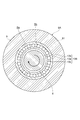
- FIG. 3 is a cross-sectional view taken along line III-III in FIG. 4 is a cross-sectional view taken along line IV-IV in FIG.
- FIG. 5 is a sectional view taken along line VV in FIG.
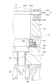
- FIG. 6 is a cross-sectional view taken along line VI-VI in FIG. It is sectional drawing which expands and shows a part containing the touchdown bearing of a rotary machine. It is an enlarged view of the part shown with the broken-line arrow A of FIG.
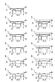
- FIG. 12 is a diagram schematically showing each example based on the rotating machine according to the first embodiment, following FIG. 11. It is a figure which shows typically each Example of the rotary machine based on the rotary machine which concerns on 2nd Embodiment.
- FIG. 14 is a diagram schematically illustrating each example based on the rotating machine according to the second embodiment, following FIG. 13.
- One aspect of the present disclosure is a rotating machine that is used in a refrigeration apparatus that uses a gas containing at least neon as a working fluid, the rotating shaft including an axial disk, an axial magnetic bearing that supports the rotating shaft, and a rotating machine.
- a motor for rotating the shaft, a turbine blade attached to one end of the rotating shaft, a compressor blade attached to the other end of the rotating shaft, and a cooling gas through which a cooling gas for cooling the motor passes A flow path, and at least a motor, an axial magnetic bearing, and a housing that accommodates the axial disk.
- the motor includes a rotor portion provided on the rotating shaft, and a stator portion facing the rotor portion.
- the disk includes a pair of support receiving surfaces sandwiched between axial magnetic bearings, and the cooling gas flow path is between the rotor portion and the stator portion. It comprises a first passage, a second flow path along at least one of the support receiving surface.
- This aspect includes a first flow path through which cooling gas passes between the rotor portion and the stator portion. That is, even if heat is generated due to a motor loss generated in the stator portion and a wind loss generated between the rotor portion and the stator portion, the temperature rise is suppressed by the cooling gas passing through the first flow path. Further, in a slight gap between the support receiving surface of the axial disk and the axial magnetic bearing, windage damage occurs due to the rotation of the axial disk, and heat is generated. However, since this aspect includes the second flow path through which the cooling gas flows along at least one of the support receiving surfaces, the influence of heat generated in the axial disk can be reduced, and the temperature rise can be suppressed.
- the housing may be a rotating machine in which a flow path port of a second flow path independent of the first flow path is formed.
- the mutual influence between the 1st channel and the 2nd channel can be reduced by cutting the edge of the 1st channel and the 2nd channel.
- the housing has a flow path provided in the centrifugal direction of the axial disk as a flow path opening of the cooling gas flow path, a pair of flow path openings provided on the compressor blade side and the turbine blade side across the stator portion. It can be set as the rotary machine provided with the path opening and the flow path opening provided in the opposite side to the stator part of an axial disk. According to this aspect, when designing the first flow path and the second flow path, optimization is facilitated.
- a touchdown bearing disposed on the turbine blade side of the axial magnetic bearing, a cooling gas passage inlet provided in the housing, a conduit connected to the cooling gas passage inlet, and a conduit
- a cooling valve provided at the inlet of the cooling gas passage may be a rotary machine provided between the touchdown bearing and the turbine blade.
- a touchdown bearing disposed further on the turbine blade side than the axial magnetic bearing, the touchdown bearing includes an inner ring on the rotating shaft side and an outer ring facing the inner ring via the rolling element.
- the housing can be a rotating machine including a baffle plate that closes a gap between the inner ring and the outer ring of the touchdown bearing. Even if the working fluid enters, the entry of the working fluid to the touch-down bearing side is prevented by the baffle plate. As a result, it is advantageous in preventing the low-temperature working fluid from reaching the motor directly.
- the cooling system 1 including the rotating machine 6A according to the embodiment is described with reference to FIGS. 1 and 2.
- the cooling system 1 is a system that cools liquid nitrogen using neon gas or a gas containing neon in part as a working fluid.
- the cooling system 1 cools liquid nitrogen by exchanging heat between the refrigeration apparatus 2 that circulates while cooling the working fluid, the refrigerant circulation apparatus 3 that circulates liquid nitrogen, and the refrigeration apparatus 2 and the refrigerant circulation apparatus 3.
- the refrigerant circulation device 3 includes a liquid nitrogen storage tank 31 and a pump unit 32 that pumps the liquid nitrogen cooled to a desired temperature by the cooling heat exchange unit 4.
- the liquid nitrogen is sent to the heat load side by driving the pump unit 32, and returns to the storage tank 31 after cooling various devices and parts to be cooled.
- the refrigeration apparatus 2 includes a rotary machine 6A according to the first embodiment and a circulation line 5.
- the circulation line 5 is a line through which a working fluid (hereinafter referred to as “circulation gas”) circulates, and the rotary machine 6A is a device that cools the circulation gas to, for example, an extremely low temperature.
- the rotary machine 6A (see FIG. 2) includes an expansion portion 6a provided with turbine blades 61 and a compression portion 6b provided with compressor blades 62.
- the rotary machine 6A employs a direct drive type drive system. In the rotating machine 6A, the rotation shaft 8 is directly rotated by the drive of the motor 7, and the turbine blade 61 and the compressor blade 62 are rotated.
- the expansion part 6a and the circulation line 5 of the rotary machine 6A are stored in a heat insulating container (not shown) such as a cold box.
- the circulation line 5 includes a low-pressure side line 5a that connects the expansion portion 6a and the compression portion 6b, and a high-pressure side line 5b that connects the compression portion 6b and the expansion portion 6a.
- the low-pressure side line 5a is a flow path in which the circulating gas cooled by the expansion in the expansion section 6a flows toward the inlet of the compression section 6b.
- the low-pressure side line 5a includes piping, valves, and the like.
- the low-pressure side line 5a is connected to the refrigerant circulation device 3 through the cooling heat exchange unit 4 so as to be able to exchange heat.
- the cooling heat exchanging unit 4 is a heat exchanger that exchanges heat between the circulating gas in the low-pressure side line 5a and the liquid nitrogen in the refrigerant circulating device 3, for example.
- the high-pressure side line 5b is a flow path through which the circulating gas discharged from the compression unit 6b flows toward the inlet of the expansion unit 6a.
- the high-pressure side line 5b includes piping, valves, and the like.
- the high-pressure side line 5b includes a cooler portion 5c for cooling the circulating gas, and a cooling gas line 51 branched from the main line on the downstream side of the cooler portion 5c.
- the main line of the high-pressure side line 5b is connected to the low-pressure side line 5a through the regenerative heat exchange unit 52 so as to be able to exchange heat.
- the regenerative heat exchange unit 52 is, for example, a heat exchanger that performs heat exchange between the circulating gas in the high-pressure side line 5b and the circulating gas in the low-pressure side line 5a.
- the refrigeration apparatus 2 includes a cooling gas line 51 that introduces cooling gas Ga that suppresses the temperature rise of the motor 7 of the rotating machine 6A into the rotating machine 6A.
- the cooling gas line 51 can be a flow path independent of the circulation line 5 described above, but in this embodiment, a part of the circulation gas flowing through the circulation line 5 is used as the cooling gas Ga.
- the cooling gas line 51 includes an introduction line 51a on the upstream side of the rotating machine 6A and an exhaust heat line 51b on the downstream side of the rotating machine 6A.
- the introduction line 51a is branched from the high-pressure side line 5b on the downstream side of the cooler portion 5c, and is connected to the rotary machine 6A.
- the exhaust heat line 51b is connected to the heat exchanging part 53a of the water cooling device 53 so as to be capable of exchanging heat, and is further connected to a low pressure side line 5a that is upstream of the compression part 6b.
- the heat exchange part 53a is a heat exchanger that performs heat exchange between the cooling gas Ga of the exhaust heat line 51b and the cooling water of the water cooling device 53, for example.
- the temperature of the cooling gas Ga rises by removing heat from the rotating machine 6A.
- the cooling gas Ga whose temperature has risen is cooled by the water cooling device 53 to the same temperature as the other circulating gas introduced into the compression unit 6b, and returned to the low-pressure side line 5a.
- the circulating gas returned to the low-pressure side line 5a again passes through the compression unit 6b and the cooler unit 5c, and substantially forms a self-circulation line.
- the circulating gas passing through the cooling gas line 51 has a special function of suppressing the temperature rise of the motor 7 of the rotating machine 6A.
- the rotating machine 6 ⁇ / b> A includes a rotating shaft 8 that includes an axial disk 81, a motor 7 that rotates the rotating shaft 8, and a rotating shaft 8. And a turbine blade 61 and a compressor blade 62 attached to the rotary shaft 8.
- the turbine blade 61 is attached to one end side of the rotating shaft 8, and the compressor blade 62 is attached to the other end side of the rotating shaft 8.
- One end side means that one end of the rotating shaft 8 and the vicinity of this end are included.
- the other end side means to include the end on the opposite side to the one end of the rotating shaft 8 and the vicinity of this end.
- the turbine blade 61 is disposed in the expansion portion 6a, and the compressor blade 62 is disposed in the compression portion 6b.
- the rotating machine 6A includes a housing 9 that houses the motor 7 and the like.
- the motor 7 includes a rotor portion 72 fixed to the rotating shaft 8 and a stator portion 71 fixed to the housing 9.
- the rotor unit 72 includes a permanent magnet or the like that creates a magnetic flux as a basis.
- the stator portion 71 includes a core portion, a coil portion wound around the core portion, and the like, and is disposed to face the rotor portion 72.
- Coil ends 71 a are formed at both ends of the stator portion 71, that is, at both ends along the axial direction of the rotating shaft 8.
- the bearing portion includes a pair of radial magnetic bearing core portions 11A and 11B, an axial magnetic bearing 12, and a pair of touchdown bearings 13A and 13B.
- the pair of radial magnetic bearing core portions 11A and 11B are installed such that the stator portion 71 is disposed between them.
- the axial magnetic bearing 12 is disposed between the radial magnetic bearing core portion 11 ⁇ / b> B and the stator portion 71 on the turbine blade 61 side.
- the axial magnetic bearing 12 includes a pair of axial magnetic pole cores 12a and 12b that magnetically levitate and support the axial disk 81 in a non-contact manner with the axial disk 81 interposed therebetween.
- one touchdown bearing 13A is installed in the vicinity of the end of the rotating shaft 8 on the compressor blade 62 side.
- the other touchdown bearing 13B is installed in the vicinity of the end of the rotating shaft 8 on the turbine blade 61 side.
- the “touch-down bearing” is sometimes called an auxiliary bearing.
- the housing 9 includes a main body 91 that houses a part of the rotary shaft 8 including the motor 7, the axial magnetic pole cores 12a and 12b, and the axial disk 81, a labyrinth seal 92 that prevents leakage of circulating gas, and a stator. And a cooling water passage 93 for cooling the portion 71.
- the labyrinth seal portion 92 is provided on each of the turbine blade 61 side and the compressor blade 62 side, and restricts the circulation gas from passing through a gap formed between the main body portion 91 and the rotary shaft 8.
- the cooling water flow path 93 is a flow path through which cooling water passes, and is connected to the stator portion 71 through a heat exchange member such as copper so as to allow heat exchange.
- a cooling gas passage 10 through which a cooling gas Ga that exhausts heat generated by motor loss and wind loss passes is formed.
- the windage loss occurs in a gap between the stator portion 71 and the rotor portion 72 of the motor 7.
- the axial disk 81 of the rotating shaft 8 is supported by the axial magnetic bearing 12, and a gap also exists between the axial disk 81 and the axial magnetic bearing 12.
- the axial disk 81 includes a pair of support receiving surfaces 81a and 81b sandwiched between the axial magnetic bearings 12, and the axial magnetic core of the axial magnetic bearing 12 faces each of the support receiving surfaces 81a and 81b. 12a and 12b are arranged. Since the axial magnetic bearing 12 supports the axial disk 81 in a magnetically levitated manner, a gap capable of causing windage loss is formed between the axial magnetic pole cores 12a and 12b and the support receiving surfaces 81a and 81b.
- the cooling gas passage 10 needs to be formed particularly in a gap where windage damage occurs.
- the flow path formed between the stator part 71 and the rotor part 72 is described as the first flow path 10a
- the flow path formed along the support receiving surfaces 81a and 81b of the axial disk 81 is the second flow path. This will be described as the flow path 10b.
- the second flow path can be divided into a path formed along the support receiving surface 81a on the stator portion 71 side and a path formed along the support receiving surface 81b on the opposite side to the stator portion 71 side. .
- the support receiving surface 81a on the side of the stator portion 71 serving as one path is described as a first support receiving surface 81a
- the support receiving surface 81b on the opposite side of the stator section 71 serving as the other path is a second support receiving surface. It will be described as a surface 81b.
- the housing 9 is formed with a plurality of flow channel openings that can function as, for example, an inlet or an outlet for the cooling gas Ga.
- the first flow path port 9 a is formed between the radial magnetic bearing core portion 11 ⁇ / b> A on the compressor blade 62 side and the stator portion 71.
- the second flow path port 9 b is formed between the stator portion 71 and the axial magnetic bearing 12.
- the third flow path port 9 c is formed between the pair of axial magnetic pole cores 12 a and 12 b of the axial magnetic bearing 12.
- the third channel port 9 c is a channel port formed in the centrifugal direction of the axial disk 81.
- the fourth flow path port 9d is formed between the axial magnetic bearing 12 and the radial magnetic bearing core portion 11B on the turbine blade 61 side.
- the fifth flow path port 9e is formed between the touchdown bearing 13B on the turbine blade 61 side and the turbine blade 61.
- the first flow path port 9a to the fifth flow path port 9e are connected to conduits through which the cooling gas Ga passes, and in particular, the flow rate can be adjusted to the conduit 14 connected to the fifth flow path port 9e.
- a control valve 15 is installed.
- the first channel port 9a and the third channel port 9c are outlets for the cooling gas Ga, and the second channel port 9b, the fourth channel port 9d and the fifth channel port 9e are cooled. It is an inlet for gas Ga. Part of the cooling gas Ga introduced from the second flow path port 9b passes between the stator portion 71 and the rotor portion 72, flows along the coil end 71a of the stator portion 71, and the first flow path port 9a. Discharged from. The flow path forming this flow is the first flow path 10 a of the cooling gas flow path 10. The remainder of the cooling gas Ga introduced from the second flow path port 9b flows along the first support receiving surface 81a of the axial disk 81 and is discharged from the third flow path port 9c. The flow path that forms this flow is the second flow path 10 b of the cooling gas flow path 10.
- the cooling gas Ga introduced from the fourth channel port 9d flows along the second support receiving surface 81b of the axial disk 81 and is discharged from the third channel port 9c.
- the flow path forming this flow is the second flow path 10 b of the cooling gas flow path 10.
- the cooling gas Ga introduced from the fifth flow path port 9e prevents the leak gas Gb from entering from the turbine blade 61 (expansion portion 6a) side.
- the flow rate of the cooling gas Ga introduced from the fifth flow path port 9 e is adjusted by the control valve 15. A detailed description of the flow rate adjustment is as follows.
- the rotary machine 6A includes a temperature sensor 16 and a control device 17.
- the temperature sensor 16 is disposed in the vicinity of the radial magnetic bearing core portion 11B on the turbine blade 61 side or in the vicinity of the labyrinth seal portion 92 on the turbine blade 61 side.
- the control device 17 monitors the temperature of the temperature sensor 16 and performs opening / closing control of the control valve 15 based on the temperature detected by the temperature sensor 16.
- the control device 17 is configured mainly by a computer including a CPU, a ROM, and a RAM, for example, and implements various functions by executing predetermined programs.
- the control device 17 is connected to the temperature sensor 16 by wire or wireless so that the data detected by the temperature sensor 16 can be acquired.
- the control device 17 is connected to the control valve 15 by wire or wireless so that a control signal for controlling the control valve 15 can be transmitted and received.
- the control device 17 stores, for example, a predetermined temperature Ta set as a reference value for monitoring.
- the predetermined temperature Ta can be arbitrarily set and is a threshold value for detecting leakage of circulating gas from the turbine blade 61 side.
- the circulating gas cooled by the expansion part 6 a is at a lower temperature than the cooling gas Ga flowing through the cooling gas channel 10.
- the control device 17 determines that there is no circulation gas leakage and closes the control valve 15.
- the control device 17 determines that the circulating gas has substantially entered as the leak gas Gb (see FIG. 9) and controls the control valve 15.
- the cooling gas Ga is introduced into the cooling gas channel 10.
- the inside is pressurized, and when pressure antagonizes with the expansion portion 6a, the ingress of the leak gas Gb is suppressed.
- the control device 17 controls the control valve 15 to be closed. If the cooling gas Ga is excessively introduced from the fifth channel port 9e, the pressure in the cooling gas channel 10 becomes excessively higher than that of the expansion part 6a, and this time, the cooling gas Ga is moved to the expansion part 6a side. There is a possibility of leaking. Therefore, it is preferable that an appropriate predetermined temperature Ta is set, and the control device 17 automatically controls the opening and closing of the control valve 15 using the temperature Ta as a threshold value.
- the housing 9 includes a support plate 95 that supports the touchdown bearing 13B on the turbine blade 61 side.
- the touch-down bearing 13B includes an inner ring 13a on the rotating shaft 8 side and an outer ring 13b facing the inner ring 13a via the rolling element 13c.
- the body portion 91 of the housing 9 is formed with a receiving portion 94 to which the outer ring 13b of the touchdown bearing 13B is attached.
- the support plate 95 is bolted to the receiving portion 94, and is in contact with the outer ring 13b to sandwich the touchdown bearing 13B with the receiving portion 94.
- the support plate 95 includes a base portion 95a that is in contact with the outer ring 13b, and a baffle plate portion 95b that protrudes from the base portion 95a to the rotating shaft 8 side.
- the baffle plate portion 95b covers the gap Sa between the outer ring 13b and the inner ring 13a, and is further disposed along the inner ring 13a.
- the gap Sa (see FIGS. 6 and 8) between the inner ring 13a and the outer ring 13b is larger than the gap Sb between the inner ring 13a and the rotating shaft 8 although there are a plurality of rolling elements 13c.
- the baffle plate portion 95b prevents the leak gas Gb from entering through the inside of the touchdown bearing 13B by closing the gap Sa.
- the baffle plate portion 95b includes a wear portion 95c having a toothed shape on the side facing the inner ring 13a, and a constricted portion 95d provided between the wear portion 95c and the base portion 95a.
- the constricted portion 95d is thinner than the other portions.
- the support plate 95 including the baffle plate portion 95b is manufactured using a SUS material that is softer than the inner ring 13a. As the SUS material, austenitic stainless steel such as SUS304 can be used.
- the baffle plate portion 95b can effectively block the gap Sa even if the inner ring 13a is moved by an internal flow such as the rotation of the rotating shaft 8 or the flow of the cooling gas Ga.
- the refrigeration apparatus 2 includes the rotating machine 6A described above, and the rotating machine 6A includes a first flow path 10a through which the cooling gas Ga passes between the rotor part 72 and the stator part 71. . That is, even if heat is generated due to a motor loss generated in the stator portion 71 and a wind loss generated between the rotor portion 72 and the stator portion 71, the temperature rise can be suppressed by the cooling gas Ga passing through the first flow path 10a. .
- the rotary machine 6A of the refrigeration apparatus 2 includes the second flow path 10b through which the cooling gas Ga flows along the support receiving surfaces 81a and 81b, the influence of heat generated in the axial disk 81 can be reduced and the temperature rises. Can be suppressed.
- the rotary machine 6A is configured such that two second flow paths 10b through which the cooling gas Ga flows are formed along both the support receiving surfaces 81a and 81b, but the second flow path 10b is formed in either one of them. If so, the temperature rise due to the windage loss of the axial disk 81 can be effectively suppressed.
- the housing 9 of the rotary machine 6A is formed with a flow path port of the second flow path 10b independent of the first flow path 10a. Specifically, a part of the cooling gas Ga introduced from the second flow path port 9b passes between the stator part 71 and the rotor part 72, and further flows along the coil end 71a of the stator part 71, It is discharged from the first flow path port 9a. The flow path forming this flow is the first flow path 10a.
- the cooling gas Ga introduced from the fourth flow path port 9d flows along the second support receiving surface 81b of the axial disk 81 and is discharged from the third flow path port 9c. The flow path forming this flow is the second flow path 10b.
- the fourth channel port 9d and the third channel port 9c that serve as the inlet and the outlet of the second channel 10b are the second channel port 9b that serves as the inlet and the outlet of the first channel 10a, and the first channel port 9b. It is independent of the flow path port 9a.
- the pressure on the turbine back surface is higher than the pressure on the compressor back surface. That is, the rotary machine 6A is in an environment in which the leak gas Gb easily enters the housing 9 from the rear surface of the turbine.
- the cooling gas channel 10 is formed in the housing 9 to retain the cooling gas Ga, and as a result, the leak gas Gb is prevented from entering and passing therethrough.
- the leak gas Gb from the rear of the turbine is used as a cooling gas.
- the turbine efficiency may be reduced, and the apparatus specifications may not be satisfied.
- the circulating gas is introduced from a path different from the leak gas Gb, and the introduced circulating gas is used as the cooling gas Ga to form the cooling gas flow path 10.
- the second flow path 10 b is formed along the support receiving surfaces 81 a and 81 b of the axial disk 81. Therefore, even if the leak gas Gb enters along the rotating shaft 8, it is possible to prevent the low-temperature leak gas Gb from reaching the motor 7 directly by the cooling gas Ga passing through the second flow path 10b. .
- the housing 9 of the rotary machine 6A has a first flow path port 9a provided on the compressor blade 62 side and the turbine blade 61 side and a second flow channel with the stator portion 71 interposed therebetween as a flow channel port of the cooling gas flow channel 10. And a roadway 9b. Further, the housing 9 includes a third flow path port 9 c provided in the centrifugal direction of the axial disk 81 and a fourth flow path port 9 d provided on the opposite side of the stator part 71 of the axial disk 81. . According to the present embodiment, various patterns can be realized as shown in the examples described later, and optimization is facilitated when designing the first flow path 10a and the second flow path 10b.
- the rotary machine 6A includes a touchdown bearing 13B disposed on the turbine blade 61 side with respect to the axial magnetic bearing 12.
- the fifth flow path port 9e is provided between the touch-down bearing 13B and the turbine blade 61 and functions as an inlet for the cooling gas Ga.
- a conduit 14 is connected to the fifth flow path port 9e, and a control valve 15 is provided in the conduit 14.
- the flow rate of the cooling gas Ga introduced or discharged from the conduit 14 can be adjusted by the control valve 15.
- the pressure (flow rate) can be adjusted so that the leak gas Gb does not enter from the turbine blade 61 side (the turbine rear surface).
- the housing 9 of the rotary machine 6A includes a baffle plate portion 95b that closes a gap between the inner ring 13a and the outer ring 13b of the touchdown bearing 13B.
- the baffle plate portion 95b prevents the leak gas Gb from entering the touch-down bearing 13B. As a result, it is advantageous in preventing the low-temperature leak gas Gb from reaching the motor 7 directly.
- the refrigeration apparatus 2 according to the second embodiment is basically the same as the refrigeration apparatus 2 according to the first embodiment except for the rotating machine 6B.
- the rotating machine 6B according to the second embodiment includes the same elements and structures as the rotating machine 6A according to the first embodiment.
- the rotary machine 6B will be mainly described, and further, the same elements and structures as those of the rotary machine 6A according to the first embodiment will be denoted by the same reference numerals, and detailed description thereof will be omitted.
- the axial disk 81 of the rotating machine 6B is provided on the compressor blade 62 side with respect to the stator portion 71. Therefore, the axial magnetic bearing 12 is provided on the compressor blade 62 side with respect to the stator portion 71.
- the first flow path port 9 a is formed between the radial magnetic bearing core portion 11 ⁇ / b> A on the compressor blade 62 side and the axial magnetic bearing 12.
- the second flow path port 9 b is formed between the pair of axial magnetic pole cores 12 a and 12 b of the axial magnetic bearing 12.
- the second channel port 9 b is a channel port formed in the centrifugal direction of the axial disk 81.
- the third flow path port 9 c is formed between the axial magnetic bearing 12 and the stator portion 71.
- the fourth flow path port 9d is formed between the stator portion 71 and the radial magnetic bearing core portion 11B on the turbine blade 61 side.
- the fifth flow path port 9e is provided between the touch-down bearing 13B on the turbine blade 61 side and the turbine blade 61, as in the first embodiment.
- the first to fifth flow passage openings 9a to 9e are connected to conduits through which the cooling gas Ga passes, respectively.
- the conduit 14 connected to the fifth flow passage opening 9e has a control valve capable of adjusting the flow rate. 15 is installed.
- the first channel port 9a, the third channel port 9c, and the fifth channel port 9e are inlets for the cooling gas Ga, and the second channel port 9b and the fourth channel port 9d are This is the outlet of the cooling gas Ga.
- the cooling gas Ga introduced from the first flow path port 9a and a part of the cooling gas Ga introduced from the third flow path port 9c each form a second flow path 10b.
- the cooling gas Ga introduced from the first flow path opening 9a flows along the second support receiving surface 81b of the axial disk 81 to form the second flow path 10b, and then the second flow It is discharged from the roadway 9b.
- the cooling gas Ga introduced from the third flow path port 9c flows along the first support receiving surface 81a of the axial disk 81 to form the second flow path 10b, and then the second flow It is discharged from the channel port 9b.
- the other cooling gas Ga introduced from the third flow path port 9c passes between the stator portion 71 and the rotor portion 72, and further flows along the coil end 71a of the stator portion 71. It is discharged from the flow path port 9d. This flow forms the first flow path 10 a of the cooling gas flow path 10.
- the rotating machine 6B according to the second embodiment has a motor loss generated in the stator unit 71 and a wind loss generated between the rotor unit 72 and the stator unit 71. Even if heat is generated, the temperature rise can be suppressed by the cooling gas Ga passing through the first flow path 10a. Further, the rotating machine 6B can reduce the influence of heat generated in the axial disk 81 due to windage loss, and can suppress the temperature rise. In addition, the rotating machine 6B according to the present embodiment has the same operations and effects as the above-described rotating machine 6A.
- each example based on the first embodiment will be described with reference to FIGS. 2, 11, and 12. Moreover, each Example based on 2nd Embodiment is demonstrated with reference to FIG.10, FIG.13 and FIG.14.
- the following first example is an example common to the first embodiment, and the second to twenty-fourth examples are based on the first embodiment.
- the first embodiment differs from the first embodiment in that the position of the inlet and outlet or a part of the flow path opening is closed.
- FIG. 11A shows a rotating machine 6A according to the second embodiment
- FIG. 11B shows a rotating machine 6A according to the third embodiment
- FIG. 11 is a rotating machine 6A according to the fourth embodiment
- FIG. 11D is a rotating machine 6A according to the fifth embodiment
- FIG. 11E is a rotating machine 6A according to the sixth embodiment.
- 11 (f) shows the rotating machine 6A according to the seventh embodiment
- FIG. 11 (g) shows the rotating machine 6A according to the eighth embodiment
- FIG. 11 is a rotating machine 6A according to the ninth embodiment
- FIG. 11 (i) is the rotating machine 6A according to the tenth embodiment
- FIG. 11 (j) is a rotating machine 6A according to the eleventh embodiment
- 11 (k) shows a rotating machine 6A according to the twelfth embodiment
- FIG. 11 (l) shows a rotating machine 6A according to the thirteenth embodiment.
- FIG. 12A shows a rotating machine 6A according to the fourteenth embodiment
- FIG. 12B shows a rotating machine 6A according to the fifteenth embodiment
- FIG. FIG. 12D shows a rotating machine 6A according to the seventeenth embodiment
- FIG. 12E shows a rotating machine 6A according to the eighteenth embodiment
- 12 (f) shows the rotating machine 6A according to the nineteenth embodiment
- FIG. 12 (g) shows the rotating machine 6A according to the twentieth embodiment
- FIG. 12A is a rotating machine 6A according to the twenty-second embodiment
- FIG. 12J is a rotating machine 6A according to the twenty-third embodiment
- FIG. 12 (k) shows a rotating machine 6A according to the twenty-fourth embodiment.
- the fourth to eleventh embodiments are embodiments in which three of all the flow passage openings 9a to 9e are used as inlets or outlets, respectively. Illustrated.
- the results of comprehensive evaluation from the viewpoints of suppressing the temperature rise of the motor and preventing the ingress of leak gas from the expansion portion are as follows. That is, a high effect was recognized in the first example, the fourteenth example, the sixteenth example, and the twenty-second example. In addition, the fourth, sixth, eighth, tenth, thirteenth, eighteenth, and twentieth examples are the same as described above. High effect was recognized.
- FIG. 10 each example based on the second embodiment is described with reference to FIGS. 10, 13, and 14.
- FIG. 10 The following twenty-fifth example is an example common to the second embodiment shown in FIG. 10, and the twenty-sixth to forty-eighth examples are based on the above-described second embodiment. However, it differs from the twenty-fifth embodiment in that the position of the inlet or outlet or a part of the flow path opening is closed.
- FIG. 13A shows a rotating machine 6B according to the 26th embodiment
- FIG. 13B shows a rotating machine 6B according to the 27th embodiment
- FIG. 13D shows the rotating machine 6B according to the twenty-ninth embodiment
- FIG. 13E shows the rotating machine 6B according to the thirty-third embodiment
- 13 (f) shows the rotating machine 6B according to the thirty-first embodiment
- FIG. 13 (g) shows the rotating machine 6B according to the thirty-second embodiment
- FIG. FIG. 13 (i) shows the rotating machine 6B according to the thirty-fourth embodiment
- FIG. 13 (j) shows the rotating machine 6B according to the thirty-fifth embodiment.
- FIG. 13 (k) shows the rotating machine 6B according to the thirty-sixth embodiment, and
- FIG. 13 (l) shows the rotating machine according to the thirty-seventh embodiment. It is a B.
- FIG. 14A shows the rotating machine 6B according to the thirty-eighth embodiment
- FIG. 14B shows the rotating machine 6B according to the thirty-ninth embodiment
- FIG. 14D shows the rotating machine 6B according to the forty-first embodiment
- FIG. 14E shows the rotating machine 6B according to the forty-second embodiment
- 14 (f) shows the rotating machine 6B according to the 43rd embodiment
- FIG. 14 (g) shows the rotating machine 6B according to the 44th embodiment
- FIG. 14 (h) shows the rotating machine 6B.
- FIG. 14 (i) shows a rotating machine 6B according to the forty-sixth embodiment
- FIG. 14 (j) shows a rotating machine 6B according to the forty-seventh embodiment
- FIG. 14 (k) shows a rotary machine 6B according to the forty-eighth embodiment.
- the twenty-eighth to thirty-fifth embodiments are examples in which three of all the channel openings 9a to 9e are used as inlets or outlets, respectively. Illustrated.
- the results of comprehensive evaluation from the viewpoint of suppressing the temperature rise of the motor and preventing the ingress of leak gas from the expansion part are as follows. That is, a high effect was recognized in the 25th example, the 38th example, the 40th example, and the 46th example. In the twenty-eighth embodiment, thirty-third embodiment, thirty-second embodiment, thirty-fourth embodiment, thirty-sixth embodiment, and forty-second embodiment, a high effect similar to the above was recognized. .
Landscapes
- Engineering & Computer Science (AREA)
- General Engineering & Computer Science (AREA)
- Mechanical Engineering (AREA)
- Physics & Mathematics (AREA)
- Thermal Sciences (AREA)
- Power Engineering (AREA)
- Structures Of Non-Positive Displacement Pumps (AREA)
Abstract
アキシャルディスクを備えた回転軸と、回転軸を支持するアキシャル磁気軸受と、回転軸を回転させるモータと、回転軸の一方の端部側に取り付けられたタービン羽根と、回転軸の他方の端部側に取り付けられたコンプレッサ羽根と、モータを冷却する冷却ガスが通過する冷却ガス流路と、少なくとも、モータ、アキシャル磁気軸受、及びアキシャルディスクを収容するハウジングと、を備え、モータは、回転軸に設けられたロータ部と、ロータ部に対向するステータ部と、を備え、アキシャルディスクは、アキシャル磁気軸受に挟まれた一対の支持受け面を備え、冷却ガス流路は、ロータ部とステータ部との間である第1流路と、少なくとも一方の支持受け面に沿った第2流路と、を備える。
Description
本開示は、作動流体として、少なくともネオンを含むガスを使用した冷凍装置に用いられる回転機械に関するものである。
ネオンを含むガスを作動流体として使用した極低温冷凍装置が知られている(特開2011-106755号参照)。また、ダイレクトドライブ式の駆動方式によってコンプレッサ及び膨張タービンの回転軸を回転させる回転機械が知られている(特開2006-46699号公報)。この種の冷凍装置に用いられる回転機械では、風損やモータ損によって機内温度が上昇するため、昇温を抑えるために機内に冷却ガスの流路が形成されている。
ダイレクトドライブ式の駆動方式で、特に、アキシャルディスクを備えた回転軸をアキシャル磁気軸受で支持する回転機械を備えた冷凍装置を想定した場合、アキシャルディスクでの風損に起因した温度上昇についても検討する必要がある。しかしながら、従来の技術では、アキシャルディスクでの昇温を抑えるための工夫について、十分な検討はなされていなかった。
本開示は、アキシャルディスクでの風損に起因した昇温を効果的に抑えることができる回転機械を説明する。
本開示の一態様は、作動流体として、少なくともネオンを含むガスを使用する冷凍装置に用いられる回転機械であって、アキシャルディスクを備えた回転軸と、回転軸を支持するアキシャル磁気軸受と、回転軸を回転させるモータと、回転軸の一方の端部側に取り付けられたタービン羽根と、回転軸の他方の端部側に取り付けられたコンプレッサ羽根と、モータを冷却する冷却ガスが通過する冷却ガス流路と、少なくとも、モータ、アキシャル磁気軸受、及びアキシャルディスクを収容するハウジングと、を備え、モータは、回転軸に設けられたロータ部と、ロータ部に対向するステータ部と、を備え、アキシャルディスクは、アキシャル磁気軸受に挟まれた一対の支持受け面を備え、冷却ガス流路は、ロータ部とステータ部との間である第1流路と、少なくとも一方の支持受け面に沿った第2流路と、を備える。
本開示の回転機械によれば、アキシャルディスクでの風損に起因した昇温を効果的に抑えることができる。
本開示の一態様は、作動流体として、少なくともネオンを含むガスを使用する冷凍装置に用いられる回転機械であって、アキシャルディスクを備えた回転軸と、回転軸を支持するアキシャル磁気軸受と、回転軸を回転させるモータと、回転軸の一方の端部側に取り付けられたタービン羽根と、回転軸の他方の端部側に取り付けられたコンプレッサ羽根と、モータを冷却する冷却ガスが通過する冷却ガス流路と、少なくとも、モータ、アキシャル磁気軸受、及びアキシャルディスクを収容するハウジングと、を備え、モータは、回転軸に設けられたロータ部と、ロータ部に対向するステータ部と、を備え、アキシャルディスクは、アキシャル磁気軸受に挟まれた一対の支持受け面を備え、冷却ガス流路は、ロータ部とステータ部との間である第1流路と、少なくとも一方の支持受け面に沿った第2流路と、を備える。
本態様は、ロータ部とステータ部との間を冷却ガスが通過する第1流路を備えている。つまり、ステータ部で生じるモータ損、及びロータ部とステータ部との間で生じる風損によって発熱しても、第1流路を通過する冷却ガスによって昇温が抑えられる。また、アキシャルディスクの支持受け面とアキシャル磁気軸受との間の僅かな隙間には、アキシャルディスクの回転によって風損が生じ、発熱する。しかしながら、本態様は、少なくとも一方の支持受け面に沿って冷却ガスが流れる第2流路を備えているので、アキシャルディスクで生じる発熱の影響を低減でき、温度上昇を抑えることができる。
いくつかの態様において、ハウジングには、第1流路から独立した第2流路の流路口が形成されている回転機械とすることができる。第1流路と第2流路との縁を切って第1流路と第2流路との間での相互の影響を低減できる。
いくつかの態様において、ハウジングは、冷却ガス流路の流路口として、ステータ部を挟んでコンプレッサ羽根側とタービン羽根側に設けられた一対の流路口と、アキシャルディスクの遠心方向に設けられた流路口と、アキシャルディスクのステータ部とは反対側に設けられた流路口とを備えている回転機械とすることができる。本態様によれば、第1流路と第2流路とを設計する際に、最適化を図り易くなる。
いくつかの態様において、アキシャル磁気軸受よりもタービン羽根側に配置されたタッチダウン軸受と、ハウジングに設けられた冷却ガス流路の入口と、冷却ガス流路の入口に接続された導管と、導管に設けられた制御弁と、を更に備え、冷却ガス流路の入口は、タッチダウン軸受とタービン羽根との間に設けられている回転機械とすることができる。制御弁によって、導管から導入される冷却ガスの流量を調整することで、タービン羽根側から作動流体が進入しないように圧力(流量)調整できる。
いくつかの態様において、アキシャル磁気軸受よりもタービン羽根側に配置されたタッチダウン軸受と、を更に備え、タッチダウン軸受は、回転軸側の内輪と、転動体を介して内輪に対向する外輪とを備え、ハウジングは、タッチダウン軸受の内輪と外輪との間の隙間を塞ぐ邪魔板を備える回転機械とすることができる。作動流体が進入してきたとしても、その作動流体のタッチダウン軸受側への進入は、邪魔板によって防がれる。その結果、低温の作動流体が直接的にモータまで到達してしまうのを防ぐ上で有利になる。
以下、本開示の実施形態について、図面を参照しながら説明する。なお、図面の説明において同一要素には同一符号を付し、重複する説明は省略する。
以下の開示では、図1及び図2を参照して、実施形態に係る回転機械6Aを備えた冷却システム1が説明されている。冷却システム1は、作動流体としてネオンガスまたは一部にネオンを含むガスを使用して、液体窒素を冷却するシステムである。冷却システム1は、作動流体を冷却しながら循環する冷凍装置2と、液体窒素を循環する冷媒循環装置3と、冷凍装置2と冷媒循環装置3との間で熱交換を行って液体窒素を冷却する冷却熱交換部4と、を備えている。
冷媒循環装置3は、液体窒素の貯留槽31と、冷却熱交換部4で所望の温度まで冷却された液体窒素を圧送するポンプ部32と、を備える。液体窒素は、ポンプ部32の駆動によって熱負荷側に送られ、冷却対象となる各種の装置や部品等を冷却した後に貯留槽31まで戻る。
冷凍装置2は、第1の実施形態に係る回転機械6Aと、循環ライン5とを備えている。循環ライン5は、作動流体(以下、「循環ガス」という)が循環するラインであり、回転機械6Aは、循環ガスを、例えば極低温にまで冷却する装置である。回転機械6A(図2参照)は、タービン羽根61が設けられた膨張部6aと、コンプレッサ羽根62が設けられた圧縮部6bとを備えている。回転機械6Aは、ダイレクトドライブ式の駆動方式を採用している。回転機械6Aは、モータ7の駆動により、直接的に回転軸8が回転し、タービン羽根61及びコンプレッサ羽根62が回転する。なお、回転機械6Aの膨張部6aや循環ライン5は、コールドボックス等の断熱容器(図示省略)内に格納されている。
循環ライン5は、膨張部6aと圧縮部6bとを接続する低圧側ライン5aと、圧縮部6bと膨張部6aとを接続する高圧側ライン5bとを備えている。低圧側ライン5aは、膨張部6aでの膨張によって冷却された循環ガスが、圧縮部6bの入口に向けて流れる流路である。低圧側ライン5aは、配管やバルブ等を備えている。低圧側ライン5aは、冷却熱交換部4を介して冷媒循環装置3と熱交換可能に接続されている。冷却熱交換部4は、例えば、低圧側ライン5aの循環ガスと冷媒循環装置3の液体窒素との間で熱交換を行う熱交換器である。
高圧側ライン5bは、圧縮部6bから排出された循環ガスが、膨張部6aの入口に向けて流れる流路である。高圧側ライン5bは、配管やバルブ等を備えている。高圧側ライン5bは、循環ガスを冷却するクーラー部5cと、クーラー部5cよりも下流側で主ラインから分岐した冷却ガスライン51と、を備えている。高圧側ライン5bの主ラインは、再生熱交換部52を介して低圧側ライン5aと熱交換可能に接続されている。再生熱交換部52は、例えば、高圧側ライン5bの循環ガスと低圧側ライン5aの循環ガスとの間で熱交換を行う熱交換器である。
冷凍装置2は、回転機械6Aのモータ7の昇温を抑える冷却ガスGaを回転機械6Aに導入する冷却ガスライン51を備えている。冷却ガスライン51は、上記の循環ライン5とは独立した流路とすることも可能であるが、本実施形態では循環ライン5を流れる循環ガスの一部を冷却ガスGaとして利用している。
具体的には、冷却ガスライン51は、回転機械6Aよりも上流側の導入ライン51aと、回転機械6Aよりも下流側の排熱ライン51bとを備えている。導入ライン51aは、クーラー部5cよりも下流側で、高圧側ライン5bから分岐し、回転機械6Aに接続されている。排熱ライン51bは、水冷装置53の熱交換部53aと熱交換可能に接続されており、更に圧縮部6bの上流側となる低圧側ライン5aに接続されている。熱交換部53aは、例えば、排熱ライン51bの冷却ガスGaと水冷装置53の冷却水との間で熱交換を行う熱交換器である。
冷却ガスGaは、回転機械6Aから抜熱することで温度が上昇する。温度が上昇した冷却ガスGaは、水冷装置53によって、圧縮部6bに導入される他の循環ガスと同温程度まで冷却され、低圧側ライン5aに戻される。低圧側ライン5aに戻された循環ガスは、再び、圧縮部6b、及びクーラー部5cを通過することになり、実質的に自己循環ラインを形成する。冷却ガスライン51を通過する循環ガスは、回転機械6Aのモータ7の昇温を抑える特別な機能を有する。
図2、図3、図4、図5、及び図6に示されるように、回転機械6Aは、アキシャルディスク81を備えた回転軸8と、回転軸8を回転させるモータ7と、回転軸8を回転自在に支持する軸受部と、回転軸8に取り付けられたタービン羽根61、及びコンプレッサ羽根62と、を備えている。タービン羽根61は回転軸8の一方の端部側に取り付けられ、コンプレッサ羽根62は回転軸8の他方の端部側に取り付けられている。一方の端部側とは、回転軸8の一方の端部及びこの端部の近傍も含む意味である。また、他方の端部側とは、回転軸8の一方の端部とは反対側の端部、及びこの端部の近傍も含む意味である。タービン羽根61は膨張部6aに配置され、コンプレッサ羽根62は圧縮部6bに配置されている。また、回転機械6Aは、モータ7等を収容するハウジング9を備えている。
モータ7は、回転軸8に固定されたロータ部72と、ハウジング9に固定されたステータ部71とを備えている。ロータ部72は、基礎となる磁束を作る永久磁石等を備える。ステータ部71は、コア部、及びコア部に巻かれたコイル部等を備えており、ロータ部72に対向して配置されている。ステータ部71の両端、つまり、回転軸8の軸線方向に沿った両端には、コイルエンド71aが形成されている。
軸受部は、一対のラジアル磁気軸受コア部11A,11B、アキシャル磁気軸受12、及び一対のタッチダウン軸受13A,13Bを備えている。一対のラジアル磁気軸受コア部11A,11Bは、互いの間にステータ部71が配置されるように設置されている。アキシャル磁気軸受12は、タービン羽根61側のラジアル磁気軸受コア部11Bとステータ部71との間に配置されている。アキシャル磁気軸受12は、アキシャルディスク81を挟んだ状態で、アキシャルディスク81を磁気浮上させて非接触支持する一対のアキシャル磁極コア12a,12bを備えている。一対のタッチダウン軸受13A,13Bのうち、一方のタッチダウン軸受13Aは回転軸8のコンプレッサ羽根62側の端部の近傍に設置されている。他方のタッチダウン軸受13Bは回転軸8のタービン羽根61側の端部の近傍に設置されている。なお、「タッチダウン軸受」は補助軸受と呼ばれることもある。
ハウジング9は、モータ7、アキシャル磁極コア12a,12b、及びアキシャルディスク81を含む回転軸8の一部を収容する本体部91と、循環ガスのリークを阻止するラビリンスシール部92と、主にステータ部71を冷却する冷却水流路93とを備えている。ラビリンスシール部92は、タービン羽根61側、及びコンプレッサ羽根62側のそれぞれに設けられており、本体部91と回転軸8との間に生じる隙間を循環ガスが通過するのを規制する。また、冷却水流路93は、冷却水が通過する流路であり、銅などの熱交換部材を介してステータ部71に熱交換可能に接続されている。
また、ハウジング9内には、モータ損や風損によって生じる熱を排熱する冷却ガスGaが通過する冷却ガス流路10が形成されている。風損は、モータ7のステータ部71とロータ部72との間の隙間で生じる。また、本実施形態に係る回転機械6Aは、回転軸8のアキシャルディスク81をアキシャル磁気軸受12で支持しており、アキシャルディスク81とアキシャル磁気軸受12との間にも隙間が存在する。具体的に説明すると、アキシャルディスク81は、アキシャル磁気軸受12によって挟まれた一対の支持受け面81a,81bを備え、各支持受け面81a,81bに対面するようにアキシャル磁気軸受12のアキシャル磁極コア12a,12bが配置されている。アキシャル磁気軸受12はアキシャルディスク81を磁気浮上させて支持しているので、アキシャル磁極コア12a,12bと支持受け面81a,81bとの間には、風損を生じ得る隙間が形成されている。
冷却ガス流路10は、特に、風損が生じる隙間に形成する必要がある。以下、ステータ部71とロータ部72との間に形成される流路は、第1流路10aとして説明され、アキシャルディスク81の支持受け面81a,81bに沿って形成される流路は第2流路10bとして説明される。なお、第2流路は、ステータ部71側の支持受け面81aに沿って形成される経路と、ステータ部71側とは反対側の支持受け面81bに沿って形成される経路とに区分できる。以下、一方の経路となるステータ部71側の支持受け面81aは第1支持受け面81aとして説明され、他方の経路となるステータ部71側とは反対側の支持受け面81bは第2支持受け面81bとして説明される。
図2及び図9に示されるように、ハウジング9には、例えば、冷却ガスGaの入口、または出口として機能し得る流路口が複数形成されている。第1の流路口9aは、コンプレッサ羽根62側のラジアル磁気軸受コア部11Aとステータ部71との間に形成されている。第2の流路口9bはステータ部71とアキシャル磁気軸受12との間に形成されている。第3の流路口9cは、アキシャル磁気軸受12の一対のアキシャル磁極コア12a,12bの間に形成されている。第3の流路口9cは、アキシャルディスク81の遠心方向に形成された流路口である。第4の流路口9dは、アキシャル磁気軸受12とタービン羽根61側のラジアル磁気軸受コア部11Bとの間に形成されている。第5の流路口9eは、タービン羽根61側のタッチダウン軸受13Bとタービン羽根61との間に形成されている。第1の流路口9a~第5の流路口9eには、それぞれ冷却ガスGaが通過する導管が接続されており、特に、第5の流路口9eに接続された導管14には流量調整可能な制御弁15が設置されている。
本実施形態では、第1の流路口9a、及び第3の流路口9cは冷却ガスGaの出口であり、第2の流路口9b、第4の流路口9d及び第5の流路口9eは冷却ガスGaの入口である。第2の流路口9bから導入された冷却ガスGaの一部は、ステータ部71とロータ部72との間を通過し、ステータ部71のコイルエンド71aに沿って流れ、第1の流路口9aから排出される。この流れを形成する流路は、冷却ガス流路10の第1流路10aである。また、第2の流路口9bから導入された冷却ガスGaの残りは、アキシャルディスク81の第1支持受け面81aに沿って流れ、第3の流路口9cから排出される。この流れを形成する流路は、冷却ガス流路10の第2流路10bである。
第4の流路口9dから導入された冷却ガスGaは、アキシャルディスク81の第2支持受け面81bに沿って流れ、第3の流路口9cから排出される。この流れを形成する流路は冷却ガス流路10の第2流路10bである。
第5の流路口9eから導入される冷却ガスGaは、タービン羽根61(膨張部6a)側からのリークガスGbの進入を阻止している。第5の流路口9eから導入される冷却ガスGaは、制御弁15によって流量調節されている。この流量調節についての詳しい説明は、以下の通りである。
回転機械6Aは、温度センサー16と制御装置17とを備えている。温度センサー16は、タービン羽根61側のラジアル磁気軸受コア部11B近傍、またはタービン羽根61側のラビリンスシール部92近傍に配置されている。制御装置17は、温度センサー16の温度を監視し、温度センサー16で検出された温度に基づいて制御弁15の開閉制御を行う。制御装置17は、例えば、CPU、ROM、RAMを含むコンピュータを主体として構成され、所定のプログラムを実行することによって各種機能を実現する。制御装置17は、温度センサー16で検出されたデータを取得可能となるように、有線または無線にて温度センサー16に接続されている。制御装置17は、制御弁15を制御する制御信号を送受信可能となるように、有線または無線にて制御弁15に接続されている。
制御装置17は、例えば、監視の基準値として設定された所定の温度Taを記憶している。所定の温度Taは任意に設定変更可能であり、タービン羽根61側からの循環ガスのリークを検出する閾値である。膨張部6aで冷却された循環ガスは、冷却ガス流路10を流れる冷却ガスGaに比べて、低温である。制御装置17は、温度センサー16で検出された温度Txが温度Taよりも高温の場合には、循環ガスのリークは無いと判断し、制御弁15を閉じておく。一方で、制御装置17は、温度センサー16で検出された温度TxがTa以下になった場合には、実質的に循環ガスがリークガスGb(図9参照)として進入してきたと判断して制御弁15を開制御し、冷却ガス流路10内に冷却ガスGaを導入する。冷却ガスGaの導入によって内部が加圧され、膨張部6aとの間で圧力拮抗するとリークガスGbの進入が抑えられる。第5の流路口9eからの冷却ガスGaの導入により、温度センサー16で検出された温度Txが温度Taよりも高くなると、制御装置17は、制御弁15を閉制御する。なお、第5の流路口9eから冷却ガスGaを過剰に導入すると、冷却ガス流路10内の圧力が膨張部6aに比べて過度に高くなり、今度は、冷却ガスGaが膨張部6a側にリークする可能性が出てくる。したがって、適切な所定の温度Taが設定され、制御装置17は、この温度Taを閾値として制御弁15の開閉を自動制御することが好ましい。
また、図7及び図8に示されるように、ハウジング9は、タービン羽根61側のタッチダウン軸受13Bを支持する支持板95を備えている。タッチダウン軸受13Bは、回転軸8側の内輪13aと、転動体13cを介して内輪13aに対向する外輪13bとを備えている。ハウジング9の本体部91には、タッチダウン軸受13Bの外輪13bが装着される受け部94が形成されている。支持板95は受け部94にボルト止めされ、外輪13bに接して受け部94との間でタッチダウン軸受13Bを挟持する。
支持板95は、外輪13bに接するベース部95aと、ベース部95aから回転軸8側に突き出した邪魔板部95bと、を備えている。邪魔板部95bは、外輪13bと内輪13aとの間の隙間Saを覆い、更に内輪13aに沿うように配置されている。内輪13aと外輪13bとの間の隙間Sa(図6、図8参照)は、複数の転動体13cが存在するものの、内輪13aと回転軸8との間の隙間Sbに比べて大きい。邪魔板部95bは、この隙間Saを塞ぐことで、タッチダウン軸受13Bの内部を通じてリークガスGbが進入するのを防止する。
なお、邪魔板部95bは、内輪13aに対面する側を歯付き形状とした摩耗部95cと、摩耗部95cとベース部95aとの間に設けられたくびれ部95dとを備えている。くびれ部95dは、他の部分に比べて薄くなっている。また、邪魔板部95bを含む支持板95は、内輪13aよりも柔らかなSUS材を使用して製造されている。SUS材はオーステナイト系ステンレス鋼、例えばSUS304等を用いることができる。邪魔板部95bは、内輪13aが回転軸8の回転や冷却ガスGaの流れなどの内部流によって動いたとしても、隙間Saを効果的に塞ぐことができる。
第1の実施形態に係る冷凍装置2は上述の回転機械6Aを備え、回転機械6Aは、ロータ部72とステータ部71との間を冷却ガスGaが通過する第1流路10aを備えている。つまり、ステータ部71で生じるモータ損、及びロータ部72とステータ部71との間で生じる風損によって発熱しても、第1流路10aを通過する冷却ガスGaによって昇温を抑えることができる。
また、アキシャルディスク81の支持受け面81a,81bとアキシャル磁気軸受12との間の隙間には、アキシャルディスク81の回転によって風損が生じ、発熱する。しかしながら、冷凍装置2の回転機械6Aは、支持受け面81a,81bに沿って冷却ガスGaが流れる第2流路10bを備えているので、アキシャルディスク81で生じる発熱の影響を低減でき、温度上昇を抑えることができる。なお、回転機械6Aは、両方の支持受け面81a,81bに沿って冷却ガスGaが流れる二つの第2流路10bが形成される態様であるが、どちらか一方に第2流路10bが形成されていれば、アキシャルディスク81の風損による昇温を効果的に抑えることができる。
また、回転機械6Aのハウジング9には、第1流路10aから独立した第2流路10bの流路口が形成されている。具体的には、第2の流路口9bから導入された冷却ガスGaの一部は、ステータ部71とロータ部72との間を通過し、更にステータ部71のコイルエンド71aに沿って流れ、第1の流路口9aから排出される。この流れを形成する流路は第1流路10aである。一方で、第4の流路口9dから導入された冷却ガスGaは、アキシャルディスク81の第2支持受け面81bに沿って流れ、第3の流路口9cから排出される。この流れを形成する流路は、第2流路10bになる。この第2流路10bの入口、及び出口となる第4の流路口9d及び第3の流路口9cは、第1流路10aの入口、及び出口となる第2の流路口9b、及び第1の流路口9aとは独立している。第2流路10bの流路口を第1流路10aから独立させることで、第1流路10aと第2流路10bとの縁を切り、冷却ガス流路10内の圧力バランスの崩れによる冷却ガスの滞留などの影響を低減できる。
また、コンプレッサ羽根62のハウジング9側(コンプレッサ背面)とタービン羽根61のハウジング9側(タービン背面)との圧力を比較した場合、タービン背面の圧力の方がコンプレッサ背面の圧力よりも高い。つまり、回転機械6Aは、タービン背面からハウジング9の内部にリークガスGbが進入し易い環境にある。しかしながら、本実施形態に係る回転機械6Aでは、ハウジング9内に冷却ガス流路10を形成することで冷却ガスGaを滞留させ、その結果、リークガスGbの進入、通過を抑えている。
なお、タービン背面からのリークガスGbを冷却ガスとする考え方もある。しかしながら、リークガスGbを利用しようとすると、タービン効率の低下を招き、装置仕様を満足できなくなる可能性がある。また、リークガスGbを冷却ガスとして利用した場合、リークガスGbの流量減少は、モータ7の適切な冷却を困難にする。そのため、本実施形態では、リークガスGbとは別の経路から循環ガスを導入し、導入した循環ガスを冷却ガスGaとして用い、冷却ガス流路10を形成している。
更に、本実施形態では、アキシャルディスク81の支持受け面81a,81bに沿って第2流路10bが形成されている。従って、リークガスGbが回転軸8に沿って進入してきても、第2流路10bを通過する冷却ガスGaにより、低温のリークガスGbが直接的にモータ7まで到達してしまうのを防ぐことができる。
また、回転機械6Aのハウジング9は、冷却ガス流路10の流路口として、ステータ部71を挟んでコンプレッサ羽根62側とタービン羽根61側に設けられた第1の流路口9aと第2の流路口9bとを備えている。また、ハウジング9は、アキシャルディスク81の遠心方向に設けられた第3の流路口9cと、アキシャルディスク81のステータ部71とは反対側に設けられた第4の流路口9dとを備えている。本実施形態によれば、後述の実施例で示されるように各種のパターンを実現でき、第1流路10aと第2流路10bとを設計する際に、最適化を図り易くなる。
また、回転機械6Aは、アキシャル磁気軸受12よりもタービン羽根61側に配置されたタッチダウン軸受13Bを備えている。第5の流路口9eは、タッチダウン軸受13Bとタービン羽根61との間に設けられており、冷却ガスGaの入口として機能している。更に、第5の流路口9eには導管14が接続されており、導管14には制御弁15が設けられている。制御弁15によって、導管14から導入または排出される冷却ガスGaの流量を調整することができる。その結果、タービン羽根61側(タービン背面)からリークガスGbが進入しないように圧力(流量)調整できるようになる。
また、回転機械6Aのハウジング9は、タッチダウン軸受13Bの内輪13aと外輪13bとの間の隙間を塞ぐ邪魔板部95bを備えている。例え、低温の循環ガスがラビリンスシール部92を超え、リークガスGbとしてハウジング9内に進入してきたとしても、邪魔板部95bによって、タッチダウン軸受13B側へのリークガスGbの進入は防がれる。その結果、低温のリークガスGbが直接的にモータ7まで到達してしまうのを防ぐ上で有利になる。
以下の開示では、図10を参照して、第2の実施形態に係る冷凍装置2が説明されている。なお、第2の実施形態に係る冷凍装置2は、回転機械6Bを除き、基本的に第1の実施形態に係る冷凍装置2と共通する。また、第2の実施形態に係る回転機械6Bは、第1の実施形態に係る回転機械6Aと同一の要素や構造を備えている。以下では、主に回転機械6Bが説明され、更に、第1の実施形態に係る回転機械6Aと同一の要素や構造については同一の符号を付して詳細な説明が省略されている。
回転機械6Bのアキシャルディスク81は、ステータ部71よりもコンプレッサ羽根62側に設けられており、従って、アキシャル磁気軸受12は、ステータ部71よりもコンプレッサ羽根62側に設けられている。
ハウジング9には、例えば、冷却ガスGaの入口、または出口として機能し得る流路口が複数形成されている。第1の流路口9aは、コンプレッサ羽根62側のラジアル磁気軸受コア部11Aとアキシャル磁気軸受12との間に形成されている。第2の流路口9bは、アキシャル磁気軸受12の一対のアキシャル磁極コア12a,12bの間に形成されている。第2の流路口9bは、アキシャルディスク81の遠心方向に形成された流路口である。第3の流路口9cは、アキシャル磁気軸受12とステータ部71との間に形成されている。第4の流路口9dは、ステータ部71とタービン羽根61側のラジアル磁気軸受コア部11Bとの間に形成されている。第5の流路口9eは、第1の実施形態と同様に、タービン羽根61側のタッチダウン軸受13Bとタービン羽根61との間に設けられている。第1~第5の流路口9a~9eには、それぞれ冷却ガスGaが通過する導管が接続されており、特に、第5の流路口9eに接続された導管14には流量調整可能な制御弁15が設置されている。
本実施形態では、第1の流路口9a、第3の流路口9c、及び第5の流路口9eは冷却ガスGaの入口であり、第2の流路口9b、及び第4の流路口9dは冷却ガスGaの出口である。第1の流路口9aから導入された冷却ガスGa、及び第3の流路口9cから導入された冷却ガスGaの一部は、それぞれ第2流路10bを形成する。具体的には、第1の流路口9aから導入された冷却ガスGaはアキシャルディスク81の第2支持受け面81bに沿って流れることで第2流路10bを形成し、その後、第2の流路口9bから排出される。また、第3の流路口9cから導入された冷却ガスGaの一部は、アキシャルディスク81の第1支持受け面81aに沿って流れることで第2流路10bを形成し、その後、第2の流路口9bから排出される。また、第3の流路口9cから導入された他の冷却ガスGaは、ステータ部71とロータ部72との間を通過し、更に、ステータ部71のコイルエンド71aに沿って流れ、第4の流路口9dから排出される。この流れは、冷却ガス流路10の第1流路10aを形成する。
第2の実施形態に係る回転機械6Bは、第1の実施形態に係る回転機械6Aと同様に、ステータ部71で生じるモータ損、及びロータ部72とステータ部71との間で生じる風損によって発熱しても、第1流路10aを通過する冷却ガスGaによって昇温を抑えることができる。また、回転機械6Bは、風損に起因してアキシャルディスク81で生じる発熱の影響を低減でき、温度上昇を抑えることができる。その他、本実施形態に係る回転機械6Bは、上述の回転機械6Aと同様の作用、効果を奏する。
以下、実施例に基づいて、より詳細に説明する。以下の開示では、図2、図11、及び図12を参照して、第1の実施形態を基礎とした各実施例が説明されている。また、図10、図13、及び図14を参照して、第2の実施形態を基礎とした各実施例が説明されている。なお、以下の第1の実施例は、上述の第1の実施形態に共通する実施例であり、第2の実施例~第24の実施例は、上述の第1の実施形態を基礎にしつつ、入口や出口の位置、または、流路口の一部が閉鎖されている点で第1の実施例と異なる。
上述の通り、第1の実施例に係る回転機械6Aは、第1の実施形態と実質的に同一である(図2参照)。また、図11の(a)は第2の実施例に係る回転機械6Aであり、図11の(b)は第3の実施例に係る回転機械6Aであり、図11の(c)は第4の実施例に係る回転機械6Aであり、図11の(d)は第5の実施例に係る回転機械6Aであり、図11の(e)は第6の実施例に係る回転機械6Aであり、図11の(f)は第7の実施例に係る回転機械6Aであり、図11の(g)は第8の実施例に係る回転機械6Aであり、図11の(h)は第9の実施例に係る回転機械6Aであり、図11の(i)は第10の実施例に係る回転機械6Aであり、図11の(j)は第11の実施例に係る回転機械6Aであり、図11の(k)は第12の実施例に係る回転機械6Aであり、図11の(l)は第13の実施例に係る回転機械6Aである。
また、図12の(a)は第14の実施例に係る回転機械6Aであり、図12の(b)は第15の実施例に係る回転機械6Aであり、図12の(c)は第16の実施例に係る回転機械6Aであり、図12の(d)は第17の実施例に係る回転機械6Aであり、図12の(e)は第18の実施例に係る回転機械6Aであり、図12の(f)は第19の実施例に係る回転機械6Aであり、図12の(g)は第20の実施例に係る回転機械6Aであり、図12の(h)は第21の実施例に係る回転機械6Aであり、図12の(i)は第22の実施例に係る回転機械6Aであり、図12の(j)は第23の実施例に係る回転機械6Aであり、図12の(k)は第24の実施例に係る回転機械6Aである。
第1の実施例(図2参照)、第22~24の実施例(図12の(i)、図12の(j)、図12の(k))は、全ての流路口9a~9eを入口、または出口として使用する実施例をそれぞれ例示している。
第2の実施例(図11の(a)参照)、第3の実施例(図11の(b)参照)は、全ての流路口9a~9eのうち、二箇所を入口、または出口として使用する実施例をそれぞれ例示している。
第4~第11の実施例(図11の(c)~図11の(j)参照)は、全ての流路口9a~9eのうち、三箇所を入口、または出口として使用する実施例をそれぞれ例示している。
第12~第21の実施例(図11の(k)、図11の(l)、図12の(a)~図12の(h)参照)は、全ての流路口9a~9eのうち、四箇所を入口、または出口として使用する実施例をそれぞれ例示している。
上記の第1~第24に係る各実施例において、モータの昇温の抑制、及び膨張部からのリークガスの進入阻止の観点で総合評価された結果は以下の通りである。つまり、第1の実施例、第14実施例、第16の実施例、及び第22の実施例は高い効果が認められた。また、第4の実施例、第6の実施例、第8の実施例、第10の実施例、第13の実施例、第18の実施例、及び第20の実施例は、上記に準じた高い効果が認められた。
また、以下の開示では、図10、図13、及び図14を参照して、第2の実施形態を基礎とした各実施例が説明されている。なお、以下の第25の実施例は、図10に示される第2の実施形態に共通する実施例であり、第26実施例~第48の実施例は、上述の第2の実施形態を基礎にしつつ、入口や出口の位置、または、流路口の一部が閉鎖されている点で第25の実施例と異なる。
上述の通り、第25の実施例に係る回転機械6Bは、第2の実施形態と実質的に同一である(図10参照)。また、図13の(a)は第26の実施例に係る回転機械6Bであり、図13の(b)は第27の実施例に係る回転機械6Bであり、図13の(c)は第28の実施例に係る回転機械6Bであり、図13の(d)は第29の実施例に係る回転機械6Bであり、図13の(e)は第30の実施例に係る回転機械6Bであり、図13の(f)は第31の実施例に係る回転機械6Bであり、図13の(g)は第32の実施例に係る回転機械6Bであり、図13の(h)は第33の実施例に係る回転機械6Bであり、図13の(i)は第34の実施例に係る回転機械6Bであり、図13の(j)は第35の実施例に係る回転機械6Bであり、図13の(k)は第36の実施例に係る回転機械6Bであり、図13の(l)は第37の実施例に係る回転機械6Bである。
また、図14の(a)は第38の実施例に係る回転機械6Bであり、図14の(b)は第39の実施例に係る回転機械6Bであり、図14の(c)は第40の実施例に係る回転機械6Bであり、図14の(d)は第41の実施例に係る回転機械6Bであり、図14の(e)は第42の実施例に係る回転機械6Bであり、図14の(f)は第43の実施例に係る回転機械6Bであり、図14の(g)は第44の実施例に係る回転機械6Bであり、図14の(h)は第45の実施例に係る回転機械6Bであり、図14の(i)は第46の実施例に係る回転機械6Bであり、図14の(j)は第47の実施例に係る回転機械6Bであり、図14の(k)は第48の実施例に係る回転機械6Bである。
第25の実施例(図10参照)、第46~48の実施例(図14の(i)、図14の(j)、図14の(k)参照)は、全ての流路口9a~9eを入口、または出口として使用する実施例をそれぞれ例示している。
第26の実施例(図13の(a)参照)、第27の実施例(図13の(b)参照)は、全ての流路口9a~9eのうち、二箇所を入口、または出口として使用する実施例をそれぞれ例示している。
第28~第35の実施例(図13の(c)~図13の(j)参照)は、全ての流路口9a~9eのうち、三箇所を入口、または出口として使用する実施例をそれぞれ例示している。
第36~第45の実施例(図13の(k)、図13の(l)、図14の(a)~図14の(h)参照)は、全ての流路口9a~9eのうち、四箇所を入口、または出口として使用する実施例をそれぞれ例示している。
上記の第25~第48に係る各実施例において、モータの昇温の抑制、及び膨張部からのリークガスの進入阻止の観点で総合評価された結果は以下の通りである。つまり、第25の実施例、第38の実施例、第40の実施例、及び第46の実施例において高い効果が認められた。また、第28の実施例、第30の実施例、第32の実施例、第34の実施例、第36の実施例、及び第42の実施例において、上記に準じた高い効果が認められた。
6A,6B 回転機械
7 モータ
8 回転軸
9 ハウジング
9a 第1の流路口
9b 第2の流路口
9c 第3の流路口
9d 第4の流路口
9e 第5の流路口
10 冷却ガス流路
10a 第1流路
10b 第2流路
12 アキシャル磁気軸受
13B タッチダウン軸受
13a 内輪
13b 外輪
13c 転動体
14 導管
15 制御弁
61 タービン羽根
62 コンプレッサ羽根
71 ステータ部
72 ロータ部
81 アキシャルディスク
81a 第1支持受け面
81b 第2支持受け面
95b 邪魔板部
Ga 冷却ガス
7 モータ
8 回転軸
9 ハウジング
9a 第1の流路口
9b 第2の流路口
9c 第3の流路口
9d 第4の流路口
9e 第5の流路口
10 冷却ガス流路
10a 第1流路
10b 第2流路
12 アキシャル磁気軸受
13B タッチダウン軸受
13a 内輪
13b 外輪
13c 転動体
14 導管
15 制御弁
61 タービン羽根
62 コンプレッサ羽根
71 ステータ部
72 ロータ部
81 アキシャルディスク
81a 第1支持受け面
81b 第2支持受け面
95b 邪魔板部
Ga 冷却ガス
Claims (5)
- 作動流体として、少なくともネオンを含むガスを使用する冷凍装置に用いられる回転機械であって、
アキシャルディスクを備えた回転軸と、
前記回転軸を支持するアキシャル磁気軸受と、
前記回転軸を回転させるモータと、
前記回転軸の一方の端部側に取り付けられたタービン羽根と、
前記回転軸の他方の端部側に取り付けられたコンプレッサ羽根と、
前記モータを冷却する冷却ガスが通過する冷却ガス流路と、
少なくとも、前記モータ、前記アキシャル磁気軸受、及び前記アキシャルディスクを収容するハウジングと、を備え、
前記モータは、前記回転軸に設けられたロータ部と、前記ロータ部に対向するステータ部と、を備え、
前記アキシャルディスクは、前記アキシャル磁気軸受に挟まれた一対の支持受け面を備え、
前記冷却ガス流路は、前記ロータ部と前記ステータ部との間である第1流路と、少なくとも一方の前記支持受け面に沿った第2流路と、を備える、回転機械。 - 前記ハウジングには、前記第1流路から独立した前記第2流路の流路口が形成されている、請求項1記載の回転機械。
- 前記ハウジングは、前記冷却ガス流路の流路口として、前記ステータ部を挟んで前記コンプレッサ羽根側と前記タービン羽根側に設けられた一対の流路口と、前記アキシャルディスクの遠心方向に設けられた流路口と、前記アキシャルディスクの前記ステータ部とは反対側に設けられた流路口とを備えている請求項1または2記載の回転機械。
- 前記アキシャル磁気軸受よりも前記タービン羽根側に配置されたタッチダウン軸受と、前記ハウジングに設けられた前記冷却ガス流路の入口と、前記冷却ガス流路の入口に接続された導管と、前記導管に設けられた制御弁と、を更に備え、
前記冷却ガス流路の入口は、前記タッチダウン軸受と前記タービン羽根との間に設けられている、請求項1~3のいずれか一項記載の回転機械。 - 前記アキシャル磁気軸受よりも前記タービン羽根側に配置されたタッチダウン軸受を備え、
前記タッチダウン軸受は、前記回転軸側の内輪と、転動体を介して前記内輪に対向する外輪とを備え、
前記ハウジングは、前記タッチダウン軸受の前記内輪と前記外輪との間の隙間を塞ぐ邪魔板を備えることを特徴とする請求項1~4のいずれか一項記載の回転機械。
Priority Applications (2)
| Application Number | Priority Date | Filing Date | Title |
|---|---|---|---|
| EP17809897.6A EP3467402A4 (en) | 2016-06-07 | 2017-03-06 | LATHE |
| US16/303,605 US20200318883A1 (en) | 2016-06-07 | 2017-03-06 | Rotary machine |
Applications Claiming Priority (2)
| Application Number | Priority Date | Filing Date | Title |
|---|---|---|---|
| JP2016113701A JP6747878B2 (ja) | 2016-06-07 | 2016-06-07 | 回転機械 |
| JP2016-113701 | 2016-06-07 |
Publications (1)
| Publication Number | Publication Date |
|---|---|
| WO2017212713A1 true WO2017212713A1 (ja) | 2017-12-14 |
Family
ID=60578536
Family Applications (1)
| Application Number | Title | Priority Date | Filing Date |
|---|---|---|---|
| PCT/JP2017/008780 Ceased WO2017212713A1 (ja) | 2016-06-07 | 2017-03-06 | 回転機械 |
Country Status (4)
| Country | Link |
|---|---|
| US (1) | US20200318883A1 (ja) |
| EP (1) | EP3467402A4 (ja) |
| JP (1) | JP6747878B2 (ja) |
| WO (1) | WO2017212713A1 (ja) |
Families Citing this family (11)
| Publication number | Priority date | Publication date | Assignee | Title |
|---|---|---|---|---|
| JP2019173615A (ja) * | 2018-03-28 | 2019-10-10 | 大陽日酸株式会社 | 回転機械 |
| US10816266B2 (en) * | 2018-08-30 | 2020-10-27 | Whirlpool Corporation | Low pressure laundry treating appliance |
| JP2020128745A (ja) * | 2019-02-01 | 2020-08-27 | ホワイト ナイト フルイド ハンドリング インコーポレーテッドWhite Knight Fluid Handling Inc. | ロータを支承し、当該ロータを磁気的に軸線方向に位置決めするための磁石を有するポンプ、及びこれに関連する方法 |
| US20220220976A1 (en) * | 2021-01-12 | 2022-07-14 | Emerson Climate Technologies, Inc. | Cooling system for centrifugal compressor and refrigeration system including same |
| IT202100026741A1 (it) * | 2021-10-19 | 2023-04-19 | Nuovo Pignone Tecnologie Srl | Circuito ad anello chiuso per fluido di raffreddamento di un cuscino magnetico per un sistema espantore-compressore |
| KR102738439B1 (ko) * | 2021-12-28 | 2024-12-04 | ㈜티앤이코리아 | 냉각 기로를 구비한 기체 사이클 히트 펌프 |
| CN115566857B (zh) * | 2022-11-15 | 2023-10-27 | 中国船舶集团有限公司第七一一研究所 | 一种用于制冷系统的磁悬浮电机密封-冷却装置及方法 |
| KR102814874B1 (ko) * | 2023-04-13 | 2025-05-30 | 한국에너지기술연구원 | 냉각 구조를 구비한 콤팬더 |
| CN117145999B (zh) * | 2023-07-21 | 2024-09-10 | 江森自控日立万宝空调(广州)有限公司 | 一种冷媒控制方法、系统、装置与存储介质 |
| CN116951806B (zh) * | 2023-08-04 | 2025-09-23 | 武汉高芯科技有限公司 | 一种背压可调节式节流制冷器 |
| JP2025118247A (ja) * | 2024-01-31 | 2025-08-13 | 株式会社荏原製作所 | 磁気軸受装置および圧縮機 |
Citations (11)
| Publication number | Priority date | Publication date | Assignee | Title |
|---|---|---|---|---|
| JPH1089296A (ja) * | 1996-09-17 | 1998-04-07 | Hitachi Ltd | 多段圧縮機 |
| JPH1155899A (ja) * | 1997-07-29 | 1999-02-26 | Ishikawajima Harima Heavy Ind Co Ltd | 超高速回転電機 |
| JP2001123997A (ja) * | 1999-10-21 | 2001-05-08 | Hitachi Ltd | 磁気軸受搭載遠心圧縮機 |
| WO2004007982A1 (ja) * | 2002-07-12 | 2004-01-22 | Mitsubishi Denki Kabushiki Kaisha | 磁気軸受スピンドル |
| WO2006011248A1 (ja) * | 2004-07-30 | 2006-02-02 | Mitsubishi Heavy Industries, Ltd. | 空気冷媒式冷却装置および空気冷媒式冷却装置を用いた空気冷媒冷熱システム |
| JP2006046699A (ja) | 2004-07-30 | 2006-02-16 | Mitsubishi Heavy Ind Ltd | 空気冷媒式冷却装置と空気冷媒式冷却装置を用いた空気冷媒冷熱システム |
| US20060163962A1 (en) * | 2003-07-04 | 2006-07-27 | Akihiro Shimada | Magnetic bearing device |
| WO2008108063A1 (ja) * | 2007-03-01 | 2008-09-12 | Ntn Corporation | モータ一体型磁気軸受装置 |
| JP2010527227A (ja) * | 2007-05-14 | 2010-08-05 | サンダイン コーポレーション | 空気冷却システムを備えた電気機械 |
| JP2011106755A (ja) | 2009-11-18 | 2011-06-02 | Taiyo Nippon Sanso Corp | 極低温冷凍装置及びその運転方法 |
| JP2015094259A (ja) * | 2013-11-11 | 2015-05-18 | 株式会社前川製作所 | 膨張機一体型圧縮機及び冷凍機並びに冷凍機の運転方法 |
Family Cites Families (5)
| Publication number | Priority date | Publication date | Assignee | Title |
|---|---|---|---|---|
| JP4969272B2 (ja) * | 2007-03-01 | 2012-07-04 | Ntn株式会社 | モータ一体型磁気軸受装置 |
| JP2010043780A (ja) * | 2008-08-12 | 2010-02-25 | Ntn Corp | 空気サイクル冷凍ユニット |
| JP2010048446A (ja) * | 2008-08-20 | 2010-03-04 | Ntn Corp | ハイブリッド空気サイクル冷凍冷却ユニット |
| FR3022963B1 (fr) * | 2014-06-27 | 2016-11-11 | Thermodyn | Systeme de refroidissement pour palier axial magnetique |
| US10415857B2 (en) * | 2015-05-01 | 2019-09-17 | Mayekawa Mfg. Co., Ltd. | Refrigerator and operation method for refrigerator |
-
2016
- 2016-06-07 JP JP2016113701A patent/JP6747878B2/ja active Active
-
2017
- 2017-03-06 US US16/303,605 patent/US20200318883A1/en not_active Abandoned
- 2017-03-06 WO PCT/JP2017/008780 patent/WO2017212713A1/ja not_active Ceased
- 2017-03-06 EP EP17809897.6A patent/EP3467402A4/en not_active Withdrawn
Patent Citations (11)
| Publication number | Priority date | Publication date | Assignee | Title |
|---|---|---|---|---|
| JPH1089296A (ja) * | 1996-09-17 | 1998-04-07 | Hitachi Ltd | 多段圧縮機 |
| JPH1155899A (ja) * | 1997-07-29 | 1999-02-26 | Ishikawajima Harima Heavy Ind Co Ltd | 超高速回転電機 |
| JP2001123997A (ja) * | 1999-10-21 | 2001-05-08 | Hitachi Ltd | 磁気軸受搭載遠心圧縮機 |
| WO2004007982A1 (ja) * | 2002-07-12 | 2004-01-22 | Mitsubishi Denki Kabushiki Kaisha | 磁気軸受スピンドル |
| US20060163962A1 (en) * | 2003-07-04 | 2006-07-27 | Akihiro Shimada | Magnetic bearing device |
| WO2006011248A1 (ja) * | 2004-07-30 | 2006-02-02 | Mitsubishi Heavy Industries, Ltd. | 空気冷媒式冷却装置および空気冷媒式冷却装置を用いた空気冷媒冷熱システム |
| JP2006046699A (ja) | 2004-07-30 | 2006-02-16 | Mitsubishi Heavy Ind Ltd | 空気冷媒式冷却装置と空気冷媒式冷却装置を用いた空気冷媒冷熱システム |
| WO2008108063A1 (ja) * | 2007-03-01 | 2008-09-12 | Ntn Corporation | モータ一体型磁気軸受装置 |
| JP2010527227A (ja) * | 2007-05-14 | 2010-08-05 | サンダイン コーポレーション | 空気冷却システムを備えた電気機械 |
| JP2011106755A (ja) | 2009-11-18 | 2011-06-02 | Taiyo Nippon Sanso Corp | 極低温冷凍装置及びその運転方法 |
| JP2015094259A (ja) * | 2013-11-11 | 2015-05-18 | 株式会社前川製作所 | 膨張機一体型圧縮機及び冷凍機並びに冷凍機の運転方法 |
Non-Patent Citations (1)
| Title |
|---|
| See also references of EP3467402A4 |
Also Published As
| Publication number | Publication date |
|---|---|
| EP3467402A4 (en) | 2020-02-12 |
| EP3467402A1 (en) | 2019-04-10 |
| JP2017219246A (ja) | 2017-12-14 |
| US20200318883A1 (en) | 2020-10-08 |
| JP6747878B2 (ja) | 2020-08-26 |
Similar Documents
| Publication | Publication Date | Title |
|---|---|---|
| WO2017212713A1 (ja) | 回転機械 | |
| KR102016827B1 (ko) | 냉동기 및 냉동기의 운전 방법 | |
| CN109477487B (zh) | 离心压缩机和用于离心压缩机的磁轴承备用系统 | |
| CN105765234B (zh) | 膨胀机一体型压缩机与冷冻机及冷冻机的运转方法 | |
| CN108779779B (zh) | 离心压缩机 | |
| US10161406B2 (en) | Compressor clearance control | |
| JP5088610B2 (ja) | 遠心圧縮機ケーシング | |
| US10036404B2 (en) | Turbo machine system | |
| EP3555481B1 (en) | Two-stage centrifugal compressor | |
| JP2012137091A (ja) | 遠心圧縮機ケーシング | |
| US8336328B2 (en) | Air cycle refrigerating/cooling system and turbine unit used therefor | |
| JP5543192B2 (ja) | 電動圧縮機及びそれを用いた蒸気圧縮式冷凍機 | |
| JP2009162464A (ja) | 空気サイクル冷凍装置 | |
| JP2008082216A (ja) | 圧縮膨張タービンシステム | |
| JP2007162493A (ja) | 圧縮膨張タービンシステム | |
| JP2019173615A (ja) | 回転機械 | |
| CN116710636A (zh) | 旋转机械以及使用了该旋转机械的制冷装置 | |
| WO2026095041A1 (en) | Seal structure and rotating machine | |
| CN218817171U (zh) | 气浮离心式压缩机储能热管理装置 | |
| JP2001123802A (ja) | タービンロータ | |
| JP2007162491A (ja) | 圧縮膨張タービンシステム | |
| JP2007162716A (ja) | 磁気軸受装置 |
Legal Events
| Date | Code | Title | Description |
|---|---|---|---|
| 121 | Ep: the epo has been informed by wipo that ep was designated in this application |
Ref document number: 17809897 Country of ref document: EP Kind code of ref document: A1 |
|
| NENP | Non-entry into the national phase |
Ref country code: DE |
|
| ENP | Entry into the national phase |
Ref document number: 2017809897 Country of ref document: EP Effective date: 20190107 |