WO2017212808A1 - 自動分析装置 - Google Patents
自動分析装置 Download PDFInfo
- Publication number
- WO2017212808A1 WO2017212808A1 PCT/JP2017/016151 JP2017016151W WO2017212808A1 WO 2017212808 A1 WO2017212808 A1 WO 2017212808A1 JP 2017016151 W JP2017016151 W JP 2017016151W WO 2017212808 A1 WO2017212808 A1 WO 2017212808A1
- Authority
- WO
- WIPO (PCT)
- Prior art keywords
- reagent
- ultraviolet light
- automatic analyzer
- ultraviolet
- container
- Prior art date
- Legal status (The legal status is an assumption and is not a legal conclusion. Google has not performed a legal analysis and makes no representation as to the accuracy of the status listed.)
- Ceased
Links
Images




Classifications
-
- G—PHYSICS
- G01—MEASURING; TESTING
- G01N—INVESTIGATING OR ANALYSING MATERIALS BY DETERMINING THEIR CHEMICAL OR PHYSICAL PROPERTIES
- G01N35/00—Automatic analysis not limited to methods or materials provided for in any single one of groups G01N1/00 - G01N33/00; Handling materials therefor
- G01N35/10—Devices for transferring samples or any liquids to, in, or from, the analysis apparatus, e.g. suction devices, injection devices
- G01N35/1002—Reagent dispensers
-
- G—PHYSICS
- G01—MEASURING; TESTING
- G01N—INVESTIGATING OR ANALYSING MATERIALS BY DETERMINING THEIR CHEMICAL OR PHYSICAL PROPERTIES
- G01N35/00—Automatic analysis not limited to methods or materials provided for in any single one of groups G01N1/00 - G01N33/00; Handling materials therefor
- G01N35/00584—Control arrangements for automatic analysers
- G01N35/00594—Quality control, including calibration or testing of components of the analyser
- G01N35/00613—Quality control
- G01N35/00663—Quality control of consumables
-
- A—HUMAN NECESSITIES
- A61—MEDICAL OR VETERINARY SCIENCE; HYGIENE
- A61L—METHODS OR APPARATUS FOR STERILISING MATERIALS OR OBJECTS IN GENERAL; DISINFECTION, STERILISATION OR DEODORISATION OF AIR; CHEMICAL ASPECTS OF BANDAGES, DRESSINGS, ABSORBENT PADS OR SURGICAL ARTICLES; MATERIALS FOR BANDAGES, DRESSINGS, ABSORBENT PADS OR SURGICAL ARTICLES
- A61L2/00—Disinfection or sterilisation of materials or objects, in general; Accessories therefor
- A61L2/02—Disinfection or sterilisation of materials or objects, in general; Accessories therefor using physical processes
- A61L2/08—Radiation
- A61L2/10—Ultraviolet [UV] radiation
-
- A—HUMAN NECESSITIES
- A61—MEDICAL OR VETERINARY SCIENCE; HYGIENE
- A61L—METHODS OR APPARATUS FOR STERILISING MATERIALS OR OBJECTS IN GENERAL; DISINFECTION, STERILISATION OR DEODORISATION OF AIR; CHEMICAL ASPECTS OF BANDAGES, DRESSINGS, ABSORBENT PADS OR SURGICAL ARTICLES; MATERIALS FOR BANDAGES, DRESSINGS, ABSORBENT PADS OR SURGICAL ARTICLES
- A61L2/00—Disinfection or sterilisation of materials or objects, in general; Accessories therefor
- A61L2/24—Apparatus using programmed or automatic operation
-
- A—HUMAN NECESSITIES
- A61—MEDICAL OR VETERINARY SCIENCE; HYGIENE
- A61L—METHODS OR APPARATUS FOR STERILISING MATERIALS OR OBJECTS IN GENERAL; DISINFECTION, STERILISATION OR DEODORISATION OF AIR; CHEMICAL ASPECTS OF BANDAGES, DRESSINGS, ABSORBENT PADS OR SURGICAL ARTICLES; MATERIALS FOR BANDAGES, DRESSINGS, ABSORBENT PADS OR SURGICAL ARTICLES
- A61L2/00—Disinfection or sterilisation of materials or objects, in general; Accessories therefor
- A61L2/26—Accessories
-
- C—CHEMISTRY; METALLURGY
- C02—TREATMENT OF WATER, WASTE WATER, SEWAGE, OR SLUDGE
- C02F—TREATMENT OF WATER, WASTE WATER, SEWAGE, OR SLUDGE
- C02F1/00—Treatment of water, waste water, or sewage
- C02F1/30—Treatment of water, waste water, or sewage by irradiation
- C02F1/32—Treatment of water, waste water, or sewage by irradiation with ultraviolet light
-
- G—PHYSICS
- G01—MEASURING; TESTING
- G01N—INVESTIGATING OR ANALYSING MATERIALS BY DETERMINING THEIR CHEMICAL OR PHYSICAL PROPERTIES
- G01N35/00—Automatic analysis not limited to methods or materials provided for in any single one of groups G01N1/00 - G01N33/00; Handling materials therefor
-
- G—PHYSICS
- G01—MEASURING; TESTING
- G01N—INVESTIGATING OR ANALYSING MATERIALS BY DETERMINING THEIR CHEMICAL OR PHYSICAL PROPERTIES
- G01N35/00—Automatic analysis not limited to methods or materials provided for in any single one of groups G01N1/00 - G01N33/00; Handling materials therefor
- G01N35/00584—Control arrangements for automatic analysers
- G01N35/00722—Communications; Identification
-
- G—PHYSICS
- G01—MEASURING; TESTING
- G01N—INVESTIGATING OR ANALYSING MATERIALS BY DETERMINING THEIR CHEMICAL OR PHYSICAL PROPERTIES
- G01N35/00—Automatic analysis not limited to methods or materials provided for in any single one of groups G01N1/00 - G01N33/00; Handling materials therefor
- G01N35/10—Devices for transferring samples or any liquids to, in, or from, the analysis apparatus, e.g. suction devices, injection devices
- G01N35/1009—Characterised by arrangements for controlling the aspiration or dispense of liquids
- G01N35/1016—Control of the volume dispensed or introduced
-
- A—HUMAN NECESSITIES
- A61—MEDICAL OR VETERINARY SCIENCE; HYGIENE
- A61L—METHODS OR APPARATUS FOR STERILISING MATERIALS OR OBJECTS IN GENERAL; DISINFECTION, STERILISATION OR DEODORISATION OF AIR; CHEMICAL ASPECTS OF BANDAGES, DRESSINGS, ABSORBENT PADS OR SURGICAL ARTICLES; MATERIALS FOR BANDAGES, DRESSINGS, ABSORBENT PADS OR SURGICAL ARTICLES
- A61L2202/00—Aspects relating to methods or apparatus for disinfecting or sterilising materials or objects
- A61L2202/10—Apparatus features
- A61L2202/14—Means for controlling sterilisation processes, data processing, presentation and storage means, e.g. sensors, controllers, programs
-
- G—PHYSICS
- G01—MEASURING; TESTING
- G01N—INVESTIGATING OR ANALYSING MATERIALS BY DETERMINING THEIR CHEMICAL OR PHYSICAL PROPERTIES
- G01N15/00—Investigating characteristics of particles; Investigating permeability, pore-volume or surface-area of porous materials
- G01N15/10—Investigating individual particles
- G01N15/1012—Calibrating particle analysers; References therefor
- G01N2015/1016—Particle flow simulating, e.g. liquid crystal cell
-
- G—PHYSICS
- G01—MEASURING; TESTING
- G01N—INVESTIGATING OR ANALYSING MATERIALS BY DETERMINING THEIR CHEMICAL OR PHYSICAL PROPERTIES
- G01N35/00—Automatic analysis not limited to methods or materials provided for in any single one of groups G01N1/00 - G01N33/00; Handling materials therefor
- G01N35/00584—Control arrangements for automatic analysers
- G01N35/00594—Quality control, including calibration or testing of components of the analyser
- G01N35/00613—Quality control
- G01N35/00663—Quality control of consumables
- G01N2035/00673—Quality control of consumables of reagents
-
- G—PHYSICS
- G01—MEASURING; TESTING
- G01N—INVESTIGATING OR ANALYSING MATERIALS BY DETERMINING THEIR CHEMICAL OR PHYSICAL PROPERTIES
- G01N35/00—Automatic analysis not limited to methods or materials provided for in any single one of groups G01N1/00 - G01N33/00; Handling materials therefor
- G01N35/00584—Control arrangements for automatic analysers
- G01N35/00722—Communications; Identification
- G01N2035/00891—Displaying information to the operator
-
- G—PHYSICS
- G01—MEASURING; TESTING
- G01N—INVESTIGATING OR ANALYSING MATERIALS BY DETERMINING THEIR CHEMICAL OR PHYSICAL PROPERTIES
- G01N35/00—Automatic analysis not limited to methods or materials provided for in any single one of groups G01N1/00 - G01N33/00; Handling materials therefor
- G01N35/10—Devices for transferring samples or any liquids to, in, or from, the analysis apparatus, e.g. suction devices, injection devices
- G01N35/1009—Characterised by arrangements for controlling the aspiration or dispense of liquids
- G01N35/1016—Control of the volume dispensed or introduced
- G01N2035/102—Preventing or detecting loss of fluid by dripping
- G01N2035/1023—Preventing or detecting loss of fluid by dripping using a valve in the tip or nozzle
-
- G—PHYSICS
- G01—MEASURING; TESTING
- G01N—INVESTIGATING OR ANALYSING MATERIALS BY DETERMINING THEIR CHEMICAL OR PHYSICAL PROPERTIES
- G01N35/00—Automatic analysis not limited to methods or materials provided for in any single one of groups G01N1/00 - G01N33/00; Handling materials therefor
- G01N35/10—Devices for transferring samples or any liquids to, in, or from, the analysis apparatus, e.g. suction devices, injection devices
- G01N35/1009—Characterised by arrangements for controlling the aspiration or dispense of liquids
- G01N2035/1025—Fluid level sensing
Definitions
- This disclosure relates to an automatic analyzer.
- sample a sample to be analyzed
- the reagent is provided to the user in a reagent container.
- the user installs the provided reagent container in or near the automatic analyzer, and inserts a suction nozzle into the mouth of the reagent container.
- the automatic analyzer sucks the reagent from the reagent container through the suction nozzle and adds the reagent to the sample, and measures the concentration of the substance to be measured contained in the sample.
- the user pulls out the suction nozzle from the reagent container and cleans or cleans the suction nozzle as necessary. Thereafter, the user replaces the new reagent container filled with the reagent with an empty reagent container, inserts the suction nozzle into the mouth of the new reagent container, and restarts the analysis operation.
- Patent Document 1 describes a sterilization container that can sterilize microorganisms contained in a liquid by irradiating the liquid in the container with ultraviolet rays.
- the irradiation light quantity when ultraviolet light is sterilized, it is necessary to appropriately select the irradiation light quantity so that the irradiation light quantity does not become insufficient or excessive.
- the irradiation light quantity if the irradiation light quantity is insufficient, the germs cannot be sufficiently sterilized, and the characteristics of the reagent may change due to the growth of the germs.
- the amount of irradiation light is excessive, the reagent components are decomposed or changed by ultraviolet light, and the characteristics of the reagent may also be changed.
- the appropriate amount of irradiation light varies depending on the remaining amount of reagent in the reagent container, and it is necessary to decrease the amount of irradiation light as the remaining amount of reagent decreases.
- the amount of irradiation light is not controlled according to the reagent remaining amount. For this reason, in the sterilization container described in Patent Document 1, the amount of irradiation light tends to be excessive as the remaining amount of the reagent decreases.
- the present invention provides a mechanism that can achieve both sterilization of the reagent and suppression of change in the property of the reagent.
- the present invention adopts, for example, the configurations described in the claims.
- the present specification includes a plurality of means for solving the above-mentioned problems. For example, “the generation of ultraviolet light that is detachably attached to the mouth of a container holding a reagent and irradiates ultraviolet light”
- a sterilization mechanism having a portion, a suction nozzle that is detachably attached to the mouth of the container together with the sterilization mechanism, and a reagent aspirated from the container via the suction nozzle is added to the sample to perform an analysis operation
- an automatic analyzer having a control unit that variably controls the amount of ultraviolet light irradiated by the ultraviolet light generation unit.
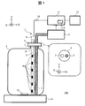
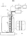
- FIG. 10 is a diagram illustrating a schematic configuration of an automatic analyzer according to Embodiment 1.
- FIG. 10 is a diagram illustrating a schematic configuration of an automatic analyzer according to a fourth embodiment.
- FIG. 10 is a diagram illustrating a schematic configuration of an automatic analyzer according to a fifth embodiment.
- FIG. 10 is a diagram illustrating a schematic configuration of an automatic analyzer according to a sixth embodiment.
- FIG. 10 is a diagram illustrating a schematic configuration of an automatic analyzer according to a seventh embodiment.
- FIG. 10 is a diagram illustrating a schematic configuration of an automatic analyzer according to a fourth embodiment.
- FIG. 10 is a diagram illustrating a schematic configuration of an automatic analyzer according to a fifth embodiment.
- FIG. 10 is a diagram illustrating a schematic configuration of an automatic analyzer according to a sixth embodiment.
- FIG. 10 is a diagram illustrating a schematic configuration of an automatic analyzer according to a seventh embodiment.
- FIG. 10 is a diagram illustrating a schematic configuration of an automatic analyzer according to an eighth embodiment.
- FIG. 10 is a diagram illustrating a schematic configuration of an automatic analyzer according to a ninth embodiment.
- FIG. 10 is a diagram showing a schematic configuration of an automatic analyzer according to a tenth embodiment.
- the term “reagent” includes not only a reaction reagent that reacts with a sample, but also a diluent, a detergent, a buffer, and a surfactant that activates an interface between an analyte and a reaction reagent.
- a reaction reagent that reacts with a sample
- a diluent e.g., a diluent
- a detergent e.g., a diluent
- a detergent e.g., a diluent
- a detergent e.g., a detergent, a buffer
- a surfactant that activates an interface between an analyte and a reaction reagent.
- the expression “sterilization” or “killing microorganisms” is also used in the meaning of “detoxifying microorganisms” in addition to the meaning of “killing microorganisms”.
- these expressions are used not only for the purpose of eradicating
- FIG. 1 shows a schematic configuration of an automatic analyzer 100 according to the present embodiment.
- the reagent container 1 received from the vendor is used by being mounted on the apparatus main body. For this reason, the user removes the lid attached at the time of distribution from the mouth of the reagent container 1 and inserts the suction nozzle 2 and the sterilizing mechanism 3 into the exposed mouth.
- the suction nozzle 2 and the sterilization mechanism 3 are fixed to the fixing portion 4.
- the fixing unit 4 is used as a new lid for the reagent container 1. By attaching the fixing part 4 to the mouth of the reagent container 1, the reagent container 1 is again sealed.
- the fixing unit 4 is detachable with respect to the mouth of the reagent container 1.
- the reagent sucked from the suction nozzle 2 is sent to the analysis unit 5 and used for analysis. Description of known portions of the configuration and processing functions of the analysis unit 5 is omitted. As a function unique to the present embodiment, there is a function of notifying the controller 11 of the remaining amount of the reagent.
- the sterilization mechanism 3 has a configuration in which a substrate 7 mounted with a plurality of ultraviolet LEDs (Light Emitting Diodes) 6 is housed in a cylindrical housing portion 8 whose bottom surface is closed, and the top surface thereof is closed with a lid 9. Have
- the number of ultraviolet LEDs 6 mounted on the substrate 7 is arbitrary, and may be one. In this embodiment, six ultraviolet LEDs 6 are arranged at equal intervals in the depth direction of the reagent container 1 (extension direction of the accommodating portion 8). But arrangement
- the ultraviolet LED 6 is attached to the substrate 7 so as to irradiate ultraviolet light only in the direction opposite to the suction nozzle 2. But you may make it arrange
- disconnecting the accommodating part 8 in parallel with respect to a horizontal surface is arbitrary, A rectangular shape and a triangular shape may be sufficient.
- the wiring 10 is drawn out from the upper surface of the lid 9 and connected to the controller 11. The other end of the wiring 10 is connected to the substrate 7 accommodated in the accommodating portion 8.
- the control unit 11 controls the amount of light emitted from the ultraviolet LED 6 via the wiring 10.
- the ultraviolet LED 6 is a so-called ultraviolet light generation unit, and emits ultraviolet light having a wavelength of 180 nm to 350 nm in a power supply state.
- a suitable wavelength is a wavelength with high sterilization efficiency with respect to the microbial species to be sterilized and hardly decompose the reagent components. More preferred is ultraviolet light having a wavelength of 240 nm to 300 nm.
- the ultraviolet LED 6 is fed through the wiring 10. Irradiation and extinction of the ultraviolet LED 6 are switched and controlled depending on whether or not power is supplied, and the illuminance of ultraviolet light is controlled by the magnitude of the supplied power.
- the housing part 8 has a function of waterproofing the ultraviolet LED 6 and the substrate 7 from the reagent. Moreover, the accommodating part 8 is formed with the material which permeate
- glass or resin that transmits ultraviolet light is used as the accommodating portion 8.
- quartz glass the transmittance of ultraviolet light is 90% or more. In this case, the attenuation of the illuminance of ultraviolet light is small, and the sterilization efficiency can be increased.
- the resin has a lower ultraviolet light transmittance than quartz glass, the mechanical strength of the container 8 increases, and the possibility of accidentally damaging the sterilization mechanism 3 when the reagent container 1 is replaced is reduced.
- the control unit 11 controls one or a combination of the current, voltage, and energization time supplied to the ultraviolet LED 6 to an appropriate value based on the remaining amount of reagent notified from the analysis unit 5.
- the control unit 11 controls any one or a combination of the current, voltage, and energization time so that the amount of ultraviolet light irradiation decreases as the amount of remaining reagent liquid decreases.
- the energization time length can be varied depending on the length of the pulse width corresponding to the energization time. As a result of these combined factors, the amount of ultraviolet light irradiated changes.
- the substrate 7 may have some or all of the functions of the control unit 11.
- the amount of ultraviolet light generated is greater than or equal to the amount of ultraviolet irradiation per unit liquid required for reagent sterilization. It controls so that it may become below the ultraviolet irradiation light quantity to do.
- the amount of ultraviolet irradiation per unit liquid necessary for sterilization of the reagent varies depending on the species of bacteria to be sterilized and the wavelength of ultraviolet light used. For this reason, the ultraviolet irradiation light quantity per unit liquid amount necessary for the sterilization of the reagent is obtained in advance by actual measurement or calculation for the combination of the bacteria species to be sterilized and the wavelength of the ultraviolet light to be used.
- the amount of ultraviolet light irradiation within which the change in reagent characteristics falls within an allowable range varies depending on the combination of reagent components (particularly, chemical bond species of the reagent) and the wavelength of ultraviolet light used. For this reason, for the combination of the reagent component and the wavelength of the ultraviolet light to be used, the ultraviolet irradiation light amount per unit liquid amount necessary for sterilization of the reagent is obtained in advance by actual measurement or calculation.
- the storage unit 11 ⁇ / b> A of the control unit 11 also stores a relationship (table) between these relationships and the reagent remaining liquid amount. Of course, the relationship between these relationships and the remaining amount of the reagent is also obtained in advance by actual measurement or calculation.
- the analysis unit 5 calculates the amount of residual reagent in the reagent container 1 from the value of the number of analyzes (or the number of measurements). Since the amount of reagent used in one analysis (or measurement) is known in advance, the amount used after replacing the reagent container 1 is calculated by multiplying the value by the number of analyzes (or the number of measurements). can do. Moreover, since the liquid amount of the reagent filled in the new reagent container 1 is also known, the residual liquid amount can be obtained by subtracting the calculated usage amount from the known liquid use. The reagent remaining liquid amount can also be obtained by using a reagent liquid level detection mechanism mounted on the analysis unit 5. Since the liquid level detection mechanism is known, detailed description thereof is omitted.
- the automatic analyzer 100 arranges the magnetic stirrer 14 as a mounting table for the reagent container 1.
- the magnetic stirrer 14 constitutes a stirring mechanism together with the stirrer 13 introduced into the reagent container 1 and rotates the stirrer 13 using magnetic force to stir the reagent.
- the stirring mechanism may be a stirring blade, or may be a system in which the suction and discharge of the reagent are repeated by the suction nozzle 2. Further, the stirring mechanism may be a system that uses convection of the reagent generated by the heat generated by the ultraviolet LED 6 that is locally disposed on the bottom side of the reagent container 1.
- the wiring 10 includes not only wiring for power supply to the ultraviolet LED 6 and control, but also a signal line for a temperature sensor such as a thermistor and a signal line for notifying the controller 11 of the state of the ultraviolet LED 6.
- the automatic analyzer 100 includes a display unit 12 that notifies the user that an appropriate reagent has been sterilized or that an abnormality has been detected.
- the user of the apparatus can know the state of the reagent and the sterilization mechanism through the screen displayed on the display unit 12.
- the display unit 12 may display an interface used for operation and control of the automatic analyzer 100, an analysis result, and an apparatus state.
- the notification content includes, for example, whether or not appropriate sterilization is performed and abnormality detection.
- the irradiation amount of ultraviolet light used for sterilization of the reagent is appropriately controlled according to the amount of the reagent remaining in the reagent container 1. Specifically, the control unit 11 can reduce the amount of ultraviolet light irradiation to an appropriate amount as the reagent remaining amount decreases.
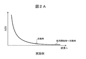
- FIG. 2A shows the time change of the measurement result of absorbance according to this example.
- the vertical axis in FIG. 2A is absorbance, and the horizontal axis is wavelength.
- the absorbance measurement value hardly changes at any wavelength from the start of use of the reagent container 1 to the replacement.
- FIG. 2A there is a change in which the absorbance slightly increases at a certain wavelength determined by the reagent component and the wavelength of ultraviolet light. However, the change is minor, indicating that the reagent properties are maintained.
- FIG. 2B shows the change over time of the absorbance measurement results when used for sterilization while keeping the amount of ultraviolet light constant (comparative example).
- the absorbance at a certain wavelength increases significantly as the sample container 1 is replaced. This increase in absorbance is caused by the decomposition or change of reagent components, and the greater the increase in absorbance, the more the characteristics of the reagent change.
- the irradiation amount of ultraviolet light used for sterilization of the reagent that is, illuminance and irradiation time
- the remaining amount of the reagent it is possible to achieve both sterilization and reagent component maintenance.
- Reagents can be used for a long time.
- the automatic analyzer 100 since the automatic analyzer 100 according to the present embodiment detachably attaches the sterilization mechanism 3 to the reagent container 1 provided by the vendor, it is not necessary to transfer the reagent when replacing the reagent. In addition, there is no fear of contamination of residual reagents and bacteria as in the case of transferring reagents.
- Example 2 In the present embodiment, a case will be described in which a countermeasure against heat generation of the ultraviolet LED 6 is applied to the automatic analyzer 100 described above.
- the ultraviolet LED 6 generates heat when irradiated with ultraviolet light. If the junction temperature of the ultraviolet LED 6 exceeds the absolute maximum rating defined in the specification, it may cause a shortening of the life of the ultraviolet LED 6 or cause a failure.
- the heat of the ultraviolet LED 6 is released to the outside of the reagent through the substrate 7, the housing portion 8 and the wiring 10 in addition to being released into the reagent.
- the ultraviolet LED located at a position higher than the liquid level of the reagent becomes difficult to release heat to the reagent.
- the bonding temperature of the ultraviolet LED 6 at a position higher than the liquid level of the reagent is higher than the bonding temperature of the ultraviolet LED at a position lower than the liquid level of the reagent, and the life is likely to be shortened.
- control unit 11 of the present embodiment is equipped with a function of selectively turning off the ultraviolet LED 6 located at a position higher than the liquid level of the reagent or reducing the amount of light based on the remaining liquid amount of the reagent. It is assumed that the position of the ultraviolet LED 6 mounted on the substrate 7 is stored in the storage unit 11A of the control unit 11. By mounting this function, it is possible to effectively prevent the shortening and failure of the ultraviolet LED 6 located at a relatively high position, and to extend the life of the sterilization mechanism 3.
- Example 3 In the above-described second embodiment, as a countermeasure against the heat generation of the ultraviolet LED 6, the ultraviolet LED 6 located at a position higher than the liquid level of the reagent is selectively turned off or the amount of light is reduced. Instead of or in addition to the functions of the second embodiment, the following functions are provided in the control unit 11.
- a temperature sensor such as a thermistor is disposed on the substrate 7 near the ultraviolet LED 6.
- the temperature sensor may be provided on a one-to-one basis with respect to the ultraviolet LED 6, or a plurality of temperature sensors may be provided at positions that are not necessarily one-to-one with the ultraviolet LED 6. The measurement result of the temperature sensor is notified to the control unit 11 through the substrate 7 and the wiring 10.
- the control unit 11 controls any one or combination of the current, voltage, and energization time supplied to the ultraviolet LED 6 so that the junction temperature of the ultraviolet LED 6 indirectly measured through the temperature sensor does not exceed a predetermined value. Thereby, the situation where the lifetime of ultraviolet LED in the position lower than the liquid level of a reagent becomes shorter than expected can be avoided, or generation
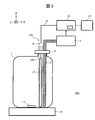
- FIG. 3 shows a schematic configuration of an automatic analyzer 200 according to the fourth embodiment.
- the same or corresponding reference numerals are given to the corresponding parts to those in FIG.
- the automatic analyzer 200 uses a sterilization mechanism 103 instead of the sterilization mechanism 3.
- the sterilization mechanism 103 is different from the sterilization mechanism 3 in that the ultraviolet lamp 15 is used for the ultraviolet light generation unit and the storage unit 108 is used.
- the ultraviolet lamp 15 a low-pressure mercury lamp or a high-pressure mercury lamp is used.
- the low-pressure mercury lamp mainly emits ultraviolet light including a wavelength of 254 nm, which has high sterilization efficiency, and a wavelength of 185 nm, which generates ozone.
- the high-pressure mercury lamp mainly emits ultraviolet light having a wavelength of 365 nm that does not contribute to sterilization, but also irradiates ultraviolet light having a wavelength of 254 nm to 334 nm that contributes to sterilization.
- the ultraviolet lamp 15 is selected from the viewpoint that it has a high sterilization efficiency with respect to the bacterial species to be sterilized and includes a suitable wavelength that is difficult to decompose the reagent components.
- the container 108 is made of glass or resin that transmits ultraviolet light. However, the function of an optical filter may be added to the housing portion 108 so that only ultraviolet light with a suitable wavelength is transmitted.
- the control unit 11 controls one or a combination of the current, voltage, and energization time supplied to the ultraviolet lamp 15 based on the remaining amount of reagent. Also in the present embodiment, the control unit 11 controls one or more of the current, voltage, and energization time so that the amount of ultraviolet light irradiation decreases as the residual amount of reagent decreases.
- the amount of ultraviolet irradiation light per unit liquid amount necessary for sterilization of the reagent varies depending on the fungus species to be sterilized, the ultraviolet lamp 15 to be used, and the filter function of the storage unit 108.
- the amount of ultraviolet irradiation light per unit liquid amount necessary for sterilization of the reagent is obtained in advance by actual measurement or calculation.
- the amount of ultraviolet irradiation light whose reagent characteristics change within an allowable range also varies depending on the combination of the reagent components (particularly chemical bond species of the reagent), the ultraviolet lamp 15, and the filter function of the container 108. Therefore, for the combination of the reagent components, the ultraviolet lamp 15 and the filter function of the storage unit 108, the amount of ultraviolet irradiation light per unit liquid amount necessary for sterilization of the reagent is obtained in advance by actual measurement or calculation.
- the storage unit 11 ⁇ / b> A of the control unit 11 stores a relationship (table) between these relationships and the reagent remaining liquid amount. Of course, the relationship between these relationships and the remaining amount of the reagent is also obtained in advance by actual measurement or calculation.
- the same stirring mechanism as in the first embodiment can be employed, but an ultraviolet lamp 15 shorter than the depth of the reagent container 1 is installed on the bottom side of the reagent container 1, and the ultraviolet lamp 15 emits.
- the reagent may be convected by heat and stirred.
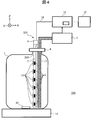
- FIG. 4 shows a schematic configuration of an automatic analyzer 300 according to the fifth embodiment.
- the automatic analyzer 300 uses a sterilization mechanism 203 instead of the sterilization mechanism 3.
- the sterilization mechanism 203 has a configuration in which the substrate 7 on which the ultraviolet LED 6 is mounted is accommodated in the accommodating portion 208.
- the accommodating portion 208 is formed of resin or metal, and an opening that transmits ultraviolet light and a window 16 that closes the opening are disposed at a position facing the ultraviolet LED 6.
- the window 16 is made of glass, for example.
- the accommodating portion 208 may be made of a material that transmits ultraviolet light or a material that does not transmit ultraviolet light.
- the metal accommodating part 208 heat dissipation can be improved compared with the case where the resin accommodating part 208 is used. For this reason, when using the metal housing portion 208, even if the ultraviolet LED 6 is driven with a larger voltage or current than in the case of the resin housing portion 208, the junction temperature of the ultraviolet LED 6 does not exceed the maximum absolute rating. Can keep. However, if the metal storage unit 208 is used, the reagent is easily heated. Therefore, when it is desired to suppress the heating of the reagent, it is desirable to use a resin-made container 208.
- the window 16 is disposed so as to close an opening provided in a region portion irradiated with the ultraviolet light irradiated from the ultraviolet LED 6 in the housing portion 208. Since the window 16 completely closes the opening of the accommodating portion 208, the ultraviolet LED 6 and the substrate 7 are waterproofed from the reagent. The ultraviolet light transmitted through the window 16 irradiates the reagent in the reagent container 1. When quartz glass is used for the window 16, the transmittance of ultraviolet light is 90% or more. In this case, the sterilization efficiency can be increased because the ultraviolet light illuminance is less attenuated.
- FIG. 5 shows a schematic configuration of an automatic analyzer 400 according to the sixth embodiment.
- the same or corresponding reference numerals are given to the corresponding parts to those in FIG.
- the automatic analyzer 400 uses a sterilization mechanism 303 instead of the sterilization mechanism 103.
- the sterilization mechanism 303 has a configuration in which the ultraviolet lamp 15 is accommodated in the accommodating portion 308.
- the housing portion 308 is formed of resin or metal, and the window 16 that transmits ultraviolet light is disposed at a position facing the ultraviolet LED 6 among them.
- the window 16 is made of glass, for example. However, an optical filter function may be added to the window 16 to transmit only a suitable wavelength.
- the container 308 may be made of a material that transmits ultraviolet light or a material that does not transmit light.
- the accommodating part 308 When the accommodating part 308 is comprised with the material which permeate
- an opening is provided in a region of the housing portion 308 that is irradiated with ultraviolet light emitted from the ultraviolet LED 6, and the window 16 is disposed so as to close the opening.
- the ultraviolet lamp 15 is waterproofed from the reagent by the accommodating portion 308 and the window 16.
- the ultraviolet light transmitted through the window 16 irradiates the reagent in the reagent container 1.
- the larger the size of the opening and the window 16 and the larger the number the higher the sterilization efficiency.
- the mechanical strength of the accommodating portion 308 is weakened. For this reason, it is desirable that the total area of the openings is not more than half of the surface area of the accommodating portion 308.
- the control unit 11 controls any one or a combination of the current, voltage, and energization time supplied to the ultraviolet lamp 15 based on the remaining amount of reagent. At this time, the control unit 11 determines that the irradiation amount of ultraviolet light generated from the ultraviolet lamp 15 is equal to or larger than the irradiation amount of ultraviolet light per unit liquid amount necessary for sterilization of the reagent, and the allowable range of change in reagent characteristics. It is controlled to be equal to or less than the amount of ultraviolet irradiation light corresponding to the upper limit of.
- the amount of ultraviolet irradiation light per unit liquid amount necessary for sterilization of the reagent differs depending on the combination of the fungus species to be sterilized, the ultraviolet lamp 15 to be used, the storage unit 308 and the filter function of the window 16. For this reason, for the combination of the fungus species to be sterilized, the ultraviolet lamp 15 to be used, the filter function of the container 308 and the window 16, the ultraviolet irradiation light amount per unit liquid amount necessary for sterilization of the reagent is obtained in advance by actual measurement or calculation. .
- the amount of ultraviolet irradiation light whose change in reagent characteristics is within an allowable range also varies depending on the combination of the reagent components (particularly chemical bond species of the reagent), the ultraviolet lamp 15 to be used, the storage unit 308 and the filter function of the window 16. For this reason, for the combination of the reagent components, the ultraviolet lamp 15 to be used, the storage unit 308, and the filter function of the window 16, the ultraviolet irradiation light amount per unit liquid amount necessary for sterilization of the reagent is obtained in advance by actual measurement or calculation.
- FIG. 6 shows a schematic configuration of an automatic analyzer 500 according to the seventh embodiment.
- the same or corresponding reference numerals are given to the portions corresponding to FIG. 1.
- the automatic analyzer 500 uses a sterilization mechanism 403 instead of the sterilization mechanism 3.
- the sterilization mechanism 403 includes a first housing portion 17 that houses the substrate 7 on which the ultraviolet LED 6 is mounted, a second housing portion 19 that houses the first housing portion 17 and its lid portion 18, and a second housing portion. It comprises 19 lid portions 20 and a heat insulating portion 21.
- the first accommodating portion 17 is sealed with a lid portion 18 through which the wiring 10 passes.
- the second accommodating portion 19 is sealed with a lid portion 20 through which the wiring 10 passes.
- a heat insulating portion 21 is disposed between the first housing portion 17 and the second housing portion 19.
- the first container 17 and the second container 19 are made of glass or resin that transmits ultraviolet light.
- quartz glass When quartz glass is used, the sterilization efficiency can be increased because the attenuation of ultraviolet light illuminance is small.
- resin when the resin is used, the mechanical strength can be increased although the transmittance of ultraviolet light is lower than that of quartz glass.
- the second container 19 is formed of resin, there is less risk of damaging the sterilization mechanism 403 by mistake when replacing the reagent container 1.
- the heat insulating part 21 is formed of air, resin, rubber or the like, and its thermal conductivity is 0.5 W / (m ⁇ K) or less.
- the first accommodating portion 17 and the second accommodating portion 19 are separated by the heat insulating portion 21 (not in direct contact).
- the presence of the heat insulating portion 21 can suppress or reduce the conduction of heat generated when the ultraviolet LED 6 irradiates ultraviolet light to the reagent, and suppress or reduce the heating of the reagent.
- the heat insulating portion 21 is arranged in a portion excluding the ultraviolet light irradiation region so as not to interfere with the ultraviolet light irradiation.
- the automatic analyzer 500 having this configuration can suppress or reduce the possibility of the reagent characteristic change due to the heating of the reagent accompanying the irradiation of ultraviolet light.
- FIG. 7 shows a schematic configuration of an automatic analyzer 600 according to the eighth embodiment.
- the automatic analyzer 600 uses a sterilization mechanism 503.
- the sterilization mechanism 503 includes a first housing portion 17 that houses the substrate 7 on which the ultraviolet LED 6 is mounted, a second housing portion 119 that houses the first housing portion 17 and its lid portion 18, and a second housing portion. 119 includes a lid portion 20 and a heat insulating portion 21.
- This double tube structure is the same as in Example 7.
- the lid 18 through which the wiring 10 penetrates seals the first housing part 17, and the lid 20 through which the wiring 10 penetrates seals the second housing part 119.
- an opening is formed in a position facing the ultraviolet LED 6 (the ultraviolet light irradiation region) in the second housing portion 119, and the opening is closed by the window 16.
- the first accommodating portion 17 is waterproofed from the reagent.
- the window 16 transmits ultraviolet light.
- the first accommodating portion 17 is made of glass or resin that transmits ultraviolet light.
- the 2nd accommodating part 119 is comprised with resin or a metal.
- the window 16 is made of glass that transmits ultraviolet light.
- the second accommodating portion 119 may be made of a material that transmits ultraviolet light or a material that does not transmit ultraviolet light.
- the automatic analyzer 600 having this configuration can suppress or reduce the possibility of the reagent characteristic change due to the heating of the reagent accompanying the irradiation of ultraviolet light.
- FIG. 8 shows a schematic configuration of an automatic analyzer 700 according to the ninth embodiment.
- the automatic analyzer 700 uses a sterilization mechanism 603.
- the sterilization mechanism and the suction nozzle 2 are configured as separate members, and each is fixed to the fixing portion 4.
- the sterilization mechanism 603 has an integrated configuration.
- a configuration in which a sterilization mechanism 603 is attached to the surface of the suction nozzle 102 is employed.
- the sterilization mechanism 603 and the suction nozzle 102 can be pulled out or inserted at the same time when the reagent is replaced, and wiping and cleaning are simplified.
- the sterilization mechanism 603 can irradiate ultraviolet light substantially uniformly in all directions.
- the number of ultraviolet LEDs 6 arranged at the same height is not limited to four, and may be one, two, three, five or more.
- interval of ultraviolet LED6 is not restricted equally, It is desirable to adjust a space
- substrate 107 which mounts ultraviolet LED6 is arrange
- the accommodating portion 408 is formed of resin or metal.
- An opening is formed at a position (ultraviolet light irradiation region) facing the ultraviolet LED 6 in the housing portion 408, and the window 16 is disposed so as to cover the opening.
- the window 16 is made of glass that transmits ultraviolet light.
- the accommodating portion 408 may be made of a material that transmits ultraviolet light or a material that does not transmit ultraviolet light.
- the accommodating portion 408 may be made of a material that transmits ultraviolet light or a material that does not transmit ultraviolet light.
- resin or metal By configuring the container 408 with resin or metal, there is less risk of damaging the sterilization mechanism 603 by mistake when replacing the reagent container 1.
- heat dissipation is improved when using metal compared to when resin is used, and the LED can be driven with a larger voltage or current within a range where the junction temperature of the ultraviolet LED 6 does not exceed the maximum absolute rating.
- the storage portion 408 is made of metal, the reagent is easily heated. Therefore, when it is desired to suppress the heating of the reagent, a resin is used for the storage portion 408.
- the lower opening end of the suction nozzle 102 is exposed to the outside through an opening provided on the bottom surface of the accommodating portion 408 so that the reagent can be sucked from the lower opening end.
- the space between the suction nozzle 102 and the opening provided in the bottom surface of the accommodating portion 408 is sealed with a seal structure or a seal material.
- the window 16 seals the opening provided in the housing portion 408. Thereby, the ultraviolet LED 6 and the substrate 107 housed in the housing portion 408 are waterproofed from the reagent.
- the automatic analyzer 700 having this configuration has a smaller blind spot in the irradiation direction of ultraviolet light than the automatic analyzer 100, and can enhance the bactericidal effect.
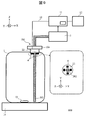
- FIG. 9 shows a schematic configuration of an automatic analyzer 800 according to the tenth embodiment.
- the automatic analyzer 800 employs a configuration in which the sterilization mechanism 703 (the ultraviolet LED 6, the substrate and the heat radiating unit 22) is attached to the mouth portion of the reagent container 1.
- the substrate and the heat radiating portion 22 are attached to the lower surface of the fixing portion 104, and when the fixing portion 104 is attached to the mouth of the reagent container 1, the substrate and the heat radiating portion 22 are connected to the mouth of the reagent container 1. Inserted inside.
- the fixing part 104, the substrate and the heat dissipation part 22 are formed with holes penetrating them, and the suction nozzle 202 is attached to these through holes.
- a plurality of ultraviolet LEDs 6 are disposed downward on the lower surface of the substrate and the heat dissipation portion 22. In FIG. 9, four ultraviolet LEDs 6 are attached to the lower surface of the substrate and the heat radiating portion 22.
- the ultraviolet LED 6 is fixed at a position where it does not touch the reagent even when the fixing portion 104 is fixed to the reagent container 1 immediately after replacement (that is, even when the liquid level of the reagent in the reagent container 1 is at the highest position). .
- the sterilization mechanism 703 of this embodiment irradiates ultraviolet light from the upper position of the reagent toward the inner wall surface of the reagent container 1 and the liquid surface of the reagent.
- the ultraviolet LED 6, the substrate, and the heat radiation part 22 it is not necessary to waterproof the ultraviolet LED 6, the substrate, and the heat radiation part 22 from the reagent.
- the reagent may touch the sterilization mechanism 703. Therefore, the sterilization mechanism 703, the substrate, and the heat dissipation part 22 may be waterproofed.
- the suction nozzle 202 may be fixed to the fixing unit 104 integrally with the sterilization mechanism 703, or may be separable from the sterilization mechanism 703. Further, part or all of the functions of the control unit 11 may be mounted on one or both of the substrate and the heat dissipation unit 22.
- the heat of the ultraviolet LED 6 is released into the air through the substrate and the heat radiation part 22. For this reason, the rise in the junction temperature of the ultraviolet LED 6 is suppressed, and the possibility that the junction temperature exceeds the absolute maximum rating determined by the specifications can be reduced. As a result, the lifetime of the ultraviolet LED 6 can be extended, and the frequency of occurrence of failures can also be reduced.
- the substrate and the heat radiating portion 22 are desirable to form with a metal having high thermal conductivity such as aluminum, copper, and stainless steel. Further, a heat sink structure may be adopted for the substrate and the heat radiating portion 22. Further, the fixing portion 104 may have a heat dissipation function. Further, similarly to the other embodiments, a temperature sensor such as a thermistor may be disposed near the ultraviolet LED 6, and the junction temperature of the ultraviolet LED 6 may be indirectly measured by the control unit 11. In this case, the control unit 11 controls one or more of the current, voltage, and energization time of the ultraviolet LED 6 based on the measured junction temperature so that the junction temperature of the ultraviolet LED 6 does not exceed the absolute maximum rating. Control.
- a temperature sensor such as a thermistor
- the automatic analyzer 800 having this configuration, it is possible to achieve both the change in the characteristics of the reagent, the suppression of the propagation of germs, and the sterilization of the reagent, as in the above-described embodiments. Further, since the reagent container 1 is used as it is by being mounted on the automatic analyzer 800, it is possible to minimize the labor and reagent quality degradation associated with the reagent transfer operation.
Landscapes
- Health & Medical Sciences (AREA)
- Life Sciences & Earth Sciences (AREA)
- General Health & Medical Sciences (AREA)
- Chemical & Material Sciences (AREA)
- Pathology (AREA)
- Immunology (AREA)
- General Physics & Mathematics (AREA)
- Biochemistry (AREA)
- Analytical Chemistry (AREA)
- Physics & Mathematics (AREA)
- Veterinary Medicine (AREA)
- Public Health (AREA)
- Animal Behavior & Ethology (AREA)
- Epidemiology (AREA)
- Engineering & Computer Science (AREA)
- Quality & Reliability (AREA)
- Hydrology & Water Resources (AREA)
- Toxicology (AREA)
- Environmental & Geological Engineering (AREA)
- Water Supply & Treatment (AREA)
- Organic Chemistry (AREA)
- Automatic Analysis And Handling Materials Therefor (AREA)
- Apparatus For Disinfection Or Sterilisation (AREA)
- Physical Water Treatments (AREA)
- Apparatus Associated With Microorganisms And Enzymes (AREA)
Abstract
自動分析装置に、試薬が保持される容器の口に対して着脱自在に装着され、紫外光を照射する紫外光発生部を有する殺菌機構と、前記殺菌機構と共に前記容器の口に対して着脱自在に装着される吸引ノズルと、前記吸引ノズルを介して前記容器から吸引した試薬を試料に添加し、分析動作を実行する分析部と、前記紫外光発生部による紫外光の照射光量を可変制御する制御部とを設ける。
Description
本開示は、自動分析装置に関する。
自動分析装置には、分析対象である試料(以下「サンプル」という。)に試薬を添加して分析動作を実行し、分析結果を導出する装置がある。通常、試薬は試薬容器に入った状態で使用者に提供される。使用者は、提供された試薬容器を自動分析装置内に又は装置近傍に設置し、試薬容器の口に吸引ノズルを挿入する。自動分析装置は、試薬容器から吸引ノズルを通じて試薬を吸引してサンプルに添加し、サンプルに含まれる被測定物質の濃度を測定する。
試薬容器内の試薬が無くなった場合、使用者は、試薬容器から吸引ノズルを引き抜き、必要に応じて吸引ノズルを洗浄又は清掃する。その後、使用者は、試薬で満たされた新しい試薬容器と空の試薬容器を交換し、吸引ノズルを新しい試薬容器の口に挿入して分析動作を再開する。
ところで、試薬容器の交換作業では、試薬に雑菌が混入し増殖する可能性がある。雑菌が増殖した場合、試薬の特性が変わり、サンプルに含まれる被測定物質の濃度を正確に定量できない可能性や分析結果の再現性が低下する可能性がある。特許文献1には、紫外線を容器内の液体に照射することにより、液体に含まれる微生物を殺菌することができる殺菌容器が記載されている。
ところで、紫外光を殺菌にする場合、照射光量が不足又は過多にならないように、照射光量を適切に選ぶ必要がある。例えば試薬容器内の試薬を紫外光による殺菌する場合において、照射光量が不足すると、雑菌を十分に殺菌することができず、雑菌の増殖により試薬の特性が変わってしまう可能性がある。一方、照射光量が過多であると、紫外光により試薬成分が分解又は変化し、やはり試薬の特性が変わってしまう可能性がある。
このため、紫外光を用いる殺菌手法では、試薬特性の変化が許容範囲内となるように紫外光の照射量を適切に選ぶ必要がある。ところが、特許文献1に記載の殺菌容器では、紫外光の照射光量の過不足による試薬の特性変化が考慮されていない。
適切な照射光量は、試薬容器内の試薬の残量によって変わり、試薬残量が少ないほど照射光量を減ずる必要がある。しかし、特許文献1に記載の殺菌容器では、試薬残量に応じた照射光量の制御は行われていない。このため、特許文献1に記載の殺菌容器では、試薬の残量が少なくなるほど、照射光量が過多になり易い。
さらに、特許文献1に記載の殺菌容器を用いて試薬の殺菌を行うには、試薬を試薬容器から殺菌容器に移し替える必要がある。しかし、移し替え作業を必要とする特許文献1に記載の手法は、新たな試薬が残留試薬で汚染されるリスク、移し替え作業中に試薬が空気と接触して雑菌が混入するリスクがいずれも高く、試薬の特性が変化する可能性がある。また、試薬容器を交換する手法に比べ、試薬を移し替えるために必要な作業時間は長くなる。
そこで、本発明は、試薬の殺菌と試薬の特性変化の抑制を両立可能な仕組みを提供する。
上記課題を解決するために、本発明は、例えば特許請求の範囲に記載の構成を採用する。本明細書は上記課題を解決する手段を複数含んでいるが、その一例を挙げるならば、「試薬が保持される容器の口に対して着脱自在に装着され、紫外光を照射する紫外光発生部を有する殺菌機構と、前記殺菌機構と共に前記容器の口に対して着脱自在に装着される吸引ノズルと、前記吸引ノズルを介して前記容器から吸引した試薬を試料に添加し、分析動作を実行する分析部と、前記紫外光発生部による紫外光の照射光量を可変制御する制御部と、を有する自動分析装置」である。
本明細書は本願の優先権の基礎となる日本国特許出願番号2016-114924号の開示内容を包含する。
本発明によれば、試薬の殺菌と試薬の特性変化の抑制とを両立することができる。前述した以外の課題、構成及び効果は、以下の実施の形態の説明により明らかにされる。
以下、図面に基づいて、本発明の実施の形態を説明する。なお、本発明の実施の態様は、後述する実施例に限定されるものではなく、その技術思想の範囲において、種々の変形が可能である。
本明細書では、「試薬」なる用語を、サンプルと反応する反応試薬だけでなく、希釈液、洗剤、緩衝液、分析対象と反応試薬との界面を活性化する界面活性剤をも含む広義の意味で使用する。また、本明細書では、「殺菌」又は「微生物を死滅させる」との表現を、「微生物を殺す」という意味以外に、「微生物を無害化する」という意味でも使用する。また、これらの表現は、菌や微生物を全滅させるという意味以外にも、菌や微生物を減少させるという意味でも使用する。
(1)実施例1
(1-1)装置構成
図1に、本実施例に係る自動分析装置100の概略構成を示す。自動分析装置100では、ベンダーから提供を受けた試薬容器1を装置本体に装着して使用する。このため、使用者は、配布時に取り付けられていた蓋を試薬容器1の口から取り外し、露出した口に吸引ノズル2と殺菌機構3を挿入する。吸引ノズル2と殺菌機構3は、固定部4に固定されている。固定部4は、試薬容器1に対する新たな蓋として用いられる。固定部4を試薬容器1の口に装着することにより、試薬容器1は再び密閉状態になる。なお、固定部4は、試薬容器1の口に対して着脱自在である。
(1-1)装置構成
図1に、本実施例に係る自動分析装置100の概略構成を示す。自動分析装置100では、ベンダーから提供を受けた試薬容器1を装置本体に装着して使用する。このため、使用者は、配布時に取り付けられていた蓋を試薬容器1の口から取り外し、露出した口に吸引ノズル2と殺菌機構3を挿入する。吸引ノズル2と殺菌機構3は、固定部4に固定されている。固定部4は、試薬容器1に対する新たな蓋として用いられる。固定部4を試薬容器1の口に装着することにより、試薬容器1は再び密閉状態になる。なお、固定部4は、試薬容器1の口に対して着脱自在である。
吸引ノズル2から吸引された試薬は、分析部5に送液され、分析に使用される。分析部5の構成や処理機能のうち既知の部分は説明を省略する。本実施例に特有の機能には、試薬の残液量を制御部11に通知する機能がある。殺菌機構3は、底面側が閉塞された円筒状の収容部8に、複数個の紫外LED(Light Emitting Diode)6を搭載した基板7を収容し、さらにその上面側を蓋部9で塞いだ構成を有する。
なお、基板7に搭載される紫外LED6の個数は任意であり、1個でも良い。本実施例では、6個の紫外LED6を試薬容器1の深さ方向(収容部8の延長方向)に等間隔に配列している。もっとも、紫外LED6の配置は、装着する試薬容器1の形状や寸法に応じて決定すれば良い。図1の場合、紫外LED6は吸引ノズル2と反対方向にのみ紫外光を照射するように基板7に取り付けられている。もっとも、紫外LED6を基板7の側面等に配置して紫外光がより広い範囲に照射されるようにしても良い。なお、収容部8を水平面に対して平行に切断した場合の形状は任意であり、矩形形状や三角形状でも良い。
蓋部9の上面からは配線10が引き出され、制御部11に接続される。なお、配線10の他端は収容部8に収容された基板7に接続される。制御部11は、配線10を介して紫外LED6の照射光量を制御する。紫外LED6は、いわゆる紫外光発生部であり、給電状態において、180nm~350nmの波長を有する紫外光を照射する。好適な波長は、殺菌対象の菌種に対して殺菌効率が高く、かつ、試薬成分を分解し難い波長である。更に好ましくは、240nm~300nmの波長を有する紫外光である。紫外LED6は、配線10を通じて給電される。給電の有無で紫外LED6の照射と消灯が切り替え制御され、給電される電力の大きさで紫外光の照度が制御される。
収容部8は、紫外LED6と基板7を試薬から防水する機能を有する。また、収容部8は、紫外LED6から照射された紫外光を透過する材質で形成される。本実施例では、収容部8として、紫外光を透過するガラスや樹脂を使用する。石英ガラスを用いる場合、紫外光の透過率は90%以上となる。この場合、紫外光の照度の減衰が少なく済み、殺菌効率を高めることができる。樹脂は、石英ガラスに比して紫外光の透過率が低いが、収容部8の機械的強度が増し、試薬容器1を交換する際に誤って殺菌機構3を破損させる可能性が少なくなる。
制御部11は、分析部5から通知される試薬の残液量に基づいて、紫外LED6に給電する電流、電圧及び通電時間のいずれか又はその組み合わせを適切な値に制御する。ここで、制御部11は、試薬の残液量が少なくなるほど、紫外光の照射光量が少なくなるように電流、電圧及び通電時間のいずれか又はその組み合わせを制御する。
電流値や電圧値が大きいほど発生する紫外光の照度は大きくなる。また、通電時間が長いほど発生する紫外光の照度は大きくなる。通電時間長は、通電時間に対応するパルス幅の長さによって可変できる。これらの複合要因の結果、紫外光の照射光量が変化する。なお、制御部11の機能の一部又は全部を基板7に持たせることもできる。
電流、電圧及び通電時間は、発生される紫外光の照射光量が、試薬の殺菌に必要となる単位液量当たりの紫外照射光量以上であり、かつ、試薬特性の変化の許容範囲の上限に相当する紫外照射光量以下となるように制御される。試薬の殺菌に必要な単位液量当たりの紫外照射光量は、殺菌対象の菌種と使用する紫外光の波長によって異なる。このため、殺菌対象の菌種と使用する紫外光の波長の組み合わせについて、試薬の殺菌に必要な単位液量当たりの紫外照射光量を、予め実測又は計算によって求める。
また、試薬特性の変化が許容範囲内に収まる紫外光の照射光量も、試薬成分(特に、試薬の化学結合種)と使用する紫外光の波長の組み合わせによって異なる。このため、試薬成分と使用する紫外光の波長の組み合わせについて、試薬の殺菌に必要な単位液量当たりの紫外照射光量を、予め実測又は計算によって求める。制御部11の記憶部11Aには、これらの関係と試薬の残液量との関係(テーブル)も格納されている。勿論、これらの関係と試薬の残液量との関係も予め実測又は計算により求める。
分析部5は、試薬容器1内の試薬残液量を分析回数(又は測定回数)の値から計算する。1回の分析(又は測定)で使用する試薬の液量は予め分かっているので、当該値に分析回数(又は測定回数)を乗算することにより、試薬容器1を交換した後の使用量を計算することができる。また、新しい試薬容器1に充填されている試薬の液量も既知であるので、算出された使用量を既知の液用から減算することで、残液量を求めることができる。なお、試薬残液量は、分析部5が搭載する試薬の液面検知機構を用いて求めることもできる。液面検知機構は既知であるので詳細な説明は省略する。
ところで、自動分析装置100は、試薬容器1の載置台としてマグネチックスターラー14を配置する。マグネチックスターラー14は、試薬容器1の内部に投入された撹拌子13と共に攪拌機構を構成し、磁力を利用して撹拌子13を回転させ、試薬を撹拌する。試薬を撹拌することにより、試薬を均一に殺菌することができる。なお、撹拌機構は、撹拌翼であっても良いし、吸引ノズル2によって試薬の吸引と吐出の繰り返す方式でも良い。また、撹拌機構は、試薬容器1の底側に局在的に配置した紫外LED6の発する熱により生じる試薬の対流を利用する方式でも良い。
配線10は、紫外LED6への給電や制御のための配線だけでなく、サーミスタ等の温度センサの信号線、紫外LED6の状態を制御部11に知らせる信号線を含む。この他、自動分析装置100は、適切な試薬の殺菌が行われたこと又は異常を検知したことを使用者に知らせる表示部12を有する。装置の使用者は、表示部12に表示される画面を通じ、試薬や殺菌機構の状態を知ることができる。なお、表示部12には、自動分析装置100の操作や制御に使用するインタフェース、分析結果や装置状態を表示しても良い。通知内容には、例えば適切な殺菌の実行の有無、異常の検知が含まれる。
(1-2)効果
前述の自動分析装置100を用いれば、試薬容器1に残存する試薬の液量に応じて試薬の殺菌に使用する紫外光の照射量を適切に制御する。具体的には、制御部11は、試薬の残量の減少に伴い、紫外光の照射光量が適正量になるように減少させることができる。
前述の自動分析装置100を用いれば、試薬容器1に残存する試薬の液量に応じて試薬の殺菌に使用する紫外光の照射量を適切に制御する。具体的には、制御部11は、試薬の残量の減少に伴い、紫外光の照射光量が適正量になるように減少させることができる。
この制御手法の採用により、照射光量不足による試薬内雑菌の増殖や照射光量過多による試薬の特性変化を抑制し、試薬の殺菌と試薬成分の維持を両立することができる。図2Aに、本実施例による吸光度(absorbance)の測定結果の時間変化を示す。図2Aの縦軸は吸光度であり、横軸は波長である。図2Aに示すように、試薬容器1の使用開始から交換時まで、吸光度の測定値はいずれの波長についてもほとんど変化しない。
なお、図2Aでは、試薬成分と紫外光の波長によって決まるある波長において吸光度がわずかに増加する変化が生じている。しかし、その変化は微小であり、試薬の特性が維持されていることを示す。図2Bに、紫外光の光量を一定に保ったまま殺菌に使用する場合(比較例)の吸光度の測定結果の時間変化を示す。試薬の残量によらず紫外光の光量を一定に保つ場合、試料容器1の交換時期に近づくほど、上記のある波長での吸光度が大幅に増加する。この吸光度の増加は、試薬成分の分解又は変化に起因しており、吸光度増加量が大きいほど試薬の特性に変化が生じている。
以上のように、試薬の殺菌に使用する紫外光の照射光量(すなわち、照度と照射時間)を試薬残量に基づいて適切に制御することにより、殺菌と試薬成分維持の両立が可能となり、より長い間、試薬を利用することが可能になる。
また、本実施例に係る自動分析装置100は、ベンダーから提供される試薬容器1に殺菌機構3を着脱自在に取り付けるため、試薬の交換に際して試薬の移し替え作業が不要である。また、試薬を移し替える場合のような、残留試薬や雑菌の混入などのおそれもない。
また、試薬容器1の交換の際には、吸引ノズル2と同様に殺菌機構3を引き抜き、必要に応じて洗浄や清掃を施して新しい試薬容器1に入れるだけで良い。このため、殺菌機構3を試薬容器1に挿入することによる運用の利便性は、殺菌機構3を試薬容器1に挿入しない場合の運用とほとんど変わらない。更に、試薬を殺菌容器(特許文献1)に移し替える際に発生した残留試薬や雑菌の混入や空気との接触によって試薬の特性が変わるリスクも無くすことができる、又は、小さくすることができる。
(2)実施例2
本実施例では、紫外LED6の発熱対策を前述の自動分析装置100に付与する場合について説明する。既知の通り、紫外LED6は、紫外光を照射すると発熱する。仕様で定められた絶対最大定格を紫外LED6の接合温度が超過すると、紫外LED6の寿命を縮める要因や故障の要因となる。
本実施例では、紫外LED6の発熱対策を前述の自動分析装置100に付与する場合について説明する。既知の通り、紫外LED6は、紫外光を照射すると発熱する。仕様で定められた絶対最大定格を紫外LED6の接合温度が超過すると、紫外LED6の寿命を縮める要因や故障の要因となる。
紫外LED6の熱は、試薬内に放出される他、基板7、収容部8及び配線10を通じて試薬の外部にも放出される。実験回数(測定回数)の増加に伴い試薬の残量が減少すると、試薬の液面よりも高い位置にある紫外LEDは熱を試薬に放出し難くなる。このため、試薬の液面よりも高い位置にある紫外LED6の接合温度は、試薬の液面よりも低い位置にある紫外LEDの接合温度よりも高くなり、寿命が短くなりやすい。
そこで、本実施例の制御部11には、試薬の残液量に基づいて、試薬の液面よりも高い位置にある紫外LED6を選択的に消灯する又はその光量を小さくする機能を搭載する。なお、基板7に搭載されている紫外LED6の位置は制御部11の記憶部11Aに記憶されているものとする。この機能の搭載により、相対的に高い位置にある紫外LED6の寿命の短縮や故障を効果的に防止でき、殺菌機構3の寿命を延ばすことができる。
(3)実施例3
前述の実施例2においては、紫外LED6の発熱対策として、試薬の液面より高い位置にある紫外LED6を選択的に消灯する又はその光量を小さくしたが、本実施例では、実施例2の機能に代えて又は実施例2の機能に追加して以下の機能を制御部11に設ける。
前述の実施例2においては、紫外LED6の発熱対策として、試薬の液面より高い位置にある紫外LED6を選択的に消灯する又はその光量を小さくしたが、本実施例では、実施例2の機能に代えて又は実施例2の機能に追加して以下の機能を制御部11に設ける。
本実施例では、紫外LED6の近くの基板7にサーミスタ等の温度センサを配置する。温度センサは、紫外LED6に対して1対1に設けても良いし、紫外LED6とは必ずしも1対1でない位置に複数個設けても良い。温度センサの測定結果は、基板7及び配線10を通じて制御部11に通知される。
制御部11は、温度センサを通じて間接的に測定された紫外LED6の接合温度が所定の値を超えないように、紫外LED6に供給する電流、電圧及び通電時間のいずれか又はその組み合わせを制御する。これにより、試薬の液面よりも低い位置にある紫外LEDの寿命が想定より短くなる事態を回避したり、故障の発生を予防したりできる。なお、制御部11による紫外LED6の制御は、個別でも良いし、事前に設定されたグループ単位で実行しても良い。
(4)実施例4
図3に、第4の実施例に係る自動分析装置200の概略構成を示す。図3には、図1との対応部分に同一又は対応する符号を付して示す。自動分析装置200では、殺菌機構3に代えて殺菌機構103を使用する。
図3に、第4の実施例に係る自動分析装置200の概略構成を示す。図3には、図1との対応部分に同一又は対応する符号を付して示す。自動分析装置200では、殺菌機構3に代えて殺菌機構103を使用する。
殺菌機構103は、紫外光発生部に紫外ランプ15を使用する点と、収容部108を使用する点で殺菌機構3と相違する。紫外ランプ15には、低圧水銀ランプ又は高圧水銀ランプを使用する。低圧水銀ランプは、殺菌効率の高い254nmの波長と、オゾンを発生させる185nmの波長を含む紫外光を主に照射する。紫外ランプ15を構成するガラスの種類により、185nmをカットするものと透過するものがある。一方、高圧水銀ランプは、殺菌に寄与しない365nmの波長の紫外光を主に照射するが、殺菌に寄与する254nm~334nmの波長の紫外光も照射する。紫外ランプ15は、殺菌対象の菌種に対して殺菌効率が高く、かつ、試薬成分を分解し難い好適な波長を含むという観点から選択する。
収容部108には、紫外光を透過するガラスや樹脂を使用する。もっとも、収容部108に光学フィルターの機能を付加し、好適な波長の紫外光のみを透過させても良い。制御部11は、試薬の残液量に基づいて、紫外ランプ15に給電する電流、電圧及び通電時間のいずれか又はその組み合わせを制御する。本実施例でも、制御部11は、試薬の残液量が少なくなるほど、紫外光の照射光量が少なくなるように電流、電圧及び通電時間のいずれか又は複数を制御する。
電流、電圧及び通電時間は、発生される紫外光の照射光量が、試薬の殺菌に必要となる単位液量当たりの紫外照射光量以上であり、かつ、試薬特性の変化の許容範囲の上限に相当する紫外照射光量以下となるように制御される。試薬の殺菌に必要な単位液量当たりの紫外照射光量は、殺菌対象の菌種と使用する紫外ランプ15と収容部108のフィルター機能によって異なる。このため、殺菌対象の菌種と使用する紫外ランプ15と収容部108のフィルター機能の組み合わせについて、試薬の殺菌に必要な単位液量当たりの紫外照射光量を、予め実測又は計算によって求める。
また、試薬特性の変化が許容範囲内となる紫外照射光量についても試薬成分(特に、試薬の化学結合種)と、紫外ランプ15と、収容部108のフィルター機能の組み合わせによって異なる。このため、試薬成分と紫外ランプ15と収容部108のフィルター機能の組み合わせについて、試薬の殺菌に必要な単位液量当たりの紫外照射光量を、予め実測又は計算によって求める。制御部11の記憶部11Aには、これらの関係と試薬の残液量との関係(テーブル)が格納されている。勿論、これらの関係と試薬の残液量との関係も予め実測又は計算により求める。
本実施例の場合にも、実施例1と同様の撹拌機構を採用可能であるが、試薬容器1の深さよりも短い紫外ランプ15を試薬容器1の底側に設置し、紫外ランプ15の発する熱で試薬に対流を起こして撹拌しても良い。
(5)実施例5
図4に、第5の実施例に係る自動分析装置300の概略構成を示す。図4には、図1との対応部分に同一又は対応する符号を付して示す。自動分析装置300では、殺菌機構3に代えて殺菌機構203を使用する。
図4に、第5の実施例に係る自動分析装置300の概略構成を示す。図4には、図1との対応部分に同一又は対応する符号を付して示す。自動分析装置300では、殺菌機構3に代えて殺菌機構203を使用する。
殺菌機構203は、紫外LED6を搭載した基板7を収容部208に収容した構成を有する。本実施例の場合、収容部208を樹脂又は金属で形成し、そのうち紫外LED6と対面する位置に紫外光を透過する開口部と、当該開口部を塞ぐ窓16を配置する。窓16は例えばガラスである。もっとも、収容部208は、紫外光を透過する材質でも、透過しない材質でも良い。樹脂又は金属製の収容部208を用いることにより、試薬容器1を交換する際に、殺菌機構203が誤って破損されるおそれを少なくできる。
なお、金属製の収容部208を用いると、樹脂製の収容部208を用いる場合に比して放熱性を向上させることができる。このため、金属製の収容部208を用いる場合、樹脂製の収容部208の場合よりも大きな電圧や電流で紫外LED6を駆動しても、紫外LED6の接合温度を最大絶対定格を超えない範囲に保つことができる。ただし、金属製の収容部208を用いると、試薬が加温され易くなる。従って、試薬の加温を抑えたい場合には、樹脂製の収容部208を用いることが望ましい。
窓16は、収容部208のうち紫外LED6から照射された紫外光が照射する領域部分に設けられた開口部を塞ぐように配置される。窓16は、収容部208の開口部を完全に塞ぐため、紫外LED6及び基板7は試薬から防水される。窓16を透過した紫外光は、試薬容器1内の試薬を照射する。窓16に石英ガラスを用いた場合、紫外光の透過率は90%以上となる。この場合、紫外光照度の減衰が少ないため、殺菌効率を高めることができる。
(6)実施例6
図5に、第6の実施例に係る自動分析装置400の概略構成を示す。図5には、図3との対応部分に同一又は対応する符号を付して示す。自動分析装置400では、殺菌機構103に代えて殺菌機構303を使用する。
図5に、第6の実施例に係る自動分析装置400の概略構成を示す。図5には、図3との対応部分に同一又は対応する符号を付して示す。自動分析装置400では、殺菌機構103に代えて殺菌機構303を使用する。
殺菌機構303は、紫外ランプ15を収容部308に収容した構成を有する。本実施例の場合、収容部308を樹脂又は金属で形成し、そのうち紫外LED6と対面する位置に紫外光を透過する窓16を配置する。窓16は例えばガラスである。もっとも、窓16に光学フィルターの機能を付加し、好適な波長のみ透過させても良い。収容部308は紫外光を透過する材質でも、透過しない材質でも良い。
収容部308を、紫外光を透過する材質で構成する場合、収容部308に光学フィルターの機能を付加し、好適な波長のみを透過させるようにしても良い。また、樹脂又は金属製の収容部308を用いれば、試薬容器1を交換する際に、殺菌機構303が誤って破損されるおそれを少なくできる。
因みに、収容部308のうち紫外LED6から照射された紫外光が照射する領域部分に開口部を設け、その開口部を塞ぐように窓16を配置する。収容部308と窓16により、紫外ランプ15は試薬から防水される。窓16を透過した紫外光は、試薬容器1内の試薬を照射する。開口部及び窓16の大きさが大きいほど、また数が多いほど、殺菌効率を高めることができる。その一方で、開口部及び窓16の大きさが大きいほど、また数が多いほど、収容部308の機械的強度は弱くなる。このため、開口部の合計面積は、収容部308の表面積の半分以下であることが望ましい。
窓16に石英ガラスを用いた場合、紫外光の透過率が90%以上となる。この場合、紫外光の照度の減衰が少ないため、殺菌効率を高めることができる。制御部11は、試薬の残液量に基づいて紫外ランプ15に給電する電流、電圧及び通電時間のいずれか又はその組み合わせを制御する。この際、制御部11は、紫外ランプ15から発生される紫外光の照射光量が、試薬の殺菌に必要となる単位液量当たりの紫外照射光量以上であり、かつ、試薬特性の変化の許容範囲の上限に相当する紫外照射光量以下となるように制御される。
試薬の殺菌に必要な単位液量当たりの紫外照射光量は、殺菌対象の菌種、使用する紫外ランプ15、収容部308及び窓16のフィルター機能の組み合わせによって異なる。このため、殺菌対象の菌種、使用する紫外ランプ15、収容部308及び窓16のフィルター機能の組み合わせについて、試薬の殺菌に必要な単位液量当たりの紫外照射光量を、予め実測又は計算によって求める。
また、試薬特性の変化が許容範囲内となる紫外照射光量についても試薬成分(特に、試薬の化学結合種)、使用する紫外ランプ15、収容部308及び窓16のフィルター機能の組み合わせによって異なる。このため、試薬成分、使用する紫外ランプ15、収容部308及び窓16のフィルター機能の組み合わせについて、試薬の殺菌に必要な単位液量当たりの紫外照射光量を、予め実測又は計算によって求める。
(7)実施例7
図6に、第7の実施例に係る自動分析装置500の概略構成を示す。図6には、図1との対応部分に同一又は対応する符号を付して示す。自動分析装置500では、殺菌機構3に代えて殺菌機構403を使用する。
図6に、第7の実施例に係る自動分析装置500の概略構成を示す。図6には、図1との対応部分に同一又は対応する符号を付して示す。自動分析装置500では、殺菌機構3に代えて殺菌機構403を使用する。
殺菌機構403は、紫外LED6を搭載した基板7を収容する第一の収容部17と、第一の収容部17とその蓋部18を収容する第二の収容部19と、第二の収容部19の蓋部20と、断熱部21で構成される。第一の収容部17は、配線10が貫通する蓋部18で密閉される。第二の収容部19は、配線10が貫通する蓋部20で密閉される。第一の収容部17と第二の収容部19の間には、断熱部21が配置される。
第一の収容部17と第二の収容部19には紫外光を透過するガラスや樹脂を使用する。石英ガラスを用いる場合、紫外光照度の減衰が少ないため殺菌効率を高めることができる。一方、樹脂を用いる場合、紫外光の透過率が石英ガラスより低下するものの、機械的強度を高めることができる。特に、第二の収容部19を樹脂で形成する場合、試薬容器1の交換の際に誤って殺菌機構403を破損させるおそれが少なくなる。
断熱部21は、空気、樹脂、ゴムその他で形成され、その熱伝導率は0.5 W/(m・K)以下である。断熱部21によって、第一の収容部17と第二の収容部19は分離される(直接接触しない)。断熱部21が存在することにより、紫外LED6が紫外光を照射する際に発する熱が試薬に伝導することを抑制又は低減でき、試薬の加温を抑制又は低減できる。
勿論、断熱部21は、紫外光の照射領域を除く部分に配置され、紫外光の照射を妨げないようになっている。この構成の自動分析装置500は、自動分析装置100に比して、紫外光の照射に伴う試薬の加温による試薬の特性変化の可能性を抑制又は低減することができる。
(8)実施例8
図7に、第8の実施例に係る自動分析装置600の概略構成を示す。図7には、図4及び図6との対応部分に同一又は対応する符号を付して示す。自動分析装置600では、殺菌機構503を使用する。
図7に、第8の実施例に係る自動分析装置600の概略構成を示す。図7には、図4及び図6との対応部分に同一又は対応する符号を付して示す。自動分析装置600では、殺菌機構503を使用する。
殺菌機構503は、紫外LED6を搭載した基板7を収容する第一の収容部17と、第一の収容部17とその蓋部18を収容する第二の収容部119と、第二の収容部119の蓋部20と、断熱部21で構成される。この二重管構造は実施例7と同様である。勿論、配線10が貫通する蓋部18は第一の収容部17を密閉し、配線10が貫通する蓋部20は第二の収容部119を密閉する。
ただし、第二の収容部119のうち紫外LED6と対面位置(紫外光の照射領域)には開口部が形成されており、当該開口部は窓16で塞がれている。この第二の収容部119と窓16によって、第一の収容部17は試薬から防水される。勿論、窓16は紫外光を透過する。
第一の収容部17は、紫外光を透過するガラスや樹脂で構成される。第二の収容部119は、樹脂又は金属で構成される。窓16は、紫外光を透過するガラスで構成される。第二の収容部119は、紫外光を透過する材質でも透過しない材質でも良い。第二の収容部119を樹脂又は金属で形成することにより、試薬容器1を交換する際に誤って殺菌機構503を破損させるおそれが少なくなる。
第一の収容部17と窓16に石英ガラスを用いる場合、紫外光照度の減衰が少なく済み、殺菌効率を高めることができる。この構成の自動分析装置600は、自動分析装置100に比して、紫外光の照射に伴う試薬の加温による試薬の特性変化の可能性を抑制又は低減することができる。
(9)実施例9
図8に、第9の実施例に係る自動分析装置700の概略構成を示す。図8には、図4との対応部分に同一又は対応する符号を付して示す。自動分析装置700では、殺菌機構603を使用する。前述した各実施例においては、殺菌機構と吸引ノズル2を別部材とし、それぞれを固定部4に固定する構成を採用したが、殺菌機構603はこれらを一体構成とする。
図8に、第9の実施例に係る自動分析装置700の概略構成を示す。図8には、図4との対応部分に同一又は対応する符号を付して示す。自動分析装置700では、殺菌機構603を使用する。前述した各実施例においては、殺菌機構と吸引ノズル2を別部材とし、それぞれを固定部4に固定する構成を採用したが、殺菌機構603はこれらを一体構成とする。
具体的には、吸引ノズル102の表面に殺菌機構603を取り付けた構成を採用する。殺菌機構603と吸引ノズル102を一体化することにより、試薬を交換する際に殺菌機構603と吸引ノズル102を同時に引き抜き又は挿入することができる他、拭き掃除が簡便になる。
図8の場合、殺菌機構603を構成する紫外LED6は、吸引ノズル102の複数の高さ位置についてそれぞれ4個ずつ取り付けられている。本実施例の場合、4個の紫外LED6は吸引ノズル102の外周に沿って等間隔に配置される。このため、殺菌機構603は、全方位について略均等に紫外光を照射することができる。勿論、同じ高さ位置に配置する紫外LED6の個数は4個に限らず、1個、2個、3個、5個以上でも良い。なお、紫外LED6の配置間隔は均等に限らず、装着する試薬容器1の形状に応じて間隔を調整することが望ましい。また、紫外LED6の配置は、吸引ノズル102の高さ毎に異なっていても良い。
なお、紫外LED6を搭載する基板107は、収容部408と吸引ノズル102の間の空間に配置される。本実施例の場合も、収容部408は樹脂又は金属で形成される。収容部408のうち紫外LED6と対向する位置(紫外光の照射領域)には開口部が形成され、当該開口部を覆うように窓16が配置される。窓16には、紫外光を透過するガラスを用いる。
収容部408は、紫外光を透過する材質でも透過しない材質でも良い。収容部408を樹脂又は金属で構成することにより、試薬容器1を交換する際に誤って殺菌機構603を破損させるおそれが少なくなる。また、金属を用いた方が樹脂を用いた場合よりも放熱性が向上し、紫外LED6の接合温度が最大絶対定格を超えない範囲で、より大きな電圧や電流で駆動できるようになる。ただし、収容部408を金属で形成すると、試薬が加温されやすくなる。従って、試薬の加温を抑えたい場合には、収容部408に樹脂を用いる。
なお、吸引ノズル102の下部開口端は、収容部408の底面に設けられた開口部から外部に露出しており、下部開口端から試薬を吸引できるようになっている。勿論、吸引ノズル102と収容部408の底面に設けられた開口部の間はシール構造又はシール材料によって密閉されている。同じく、窓16は、収容部408に設けられた開口部を密閉する。これにより、収容部408に収容される紫外LED6及び基板107は試薬から防水されている。
この構成の自動分析装置700は、自動分析装置100に比して、紫外光の照射方向の死角が少なくなり、殺菌効果を高めることができる。
(10)実施例10
図9に、第10の実施例に係る自動分析装置800の概略構成を示す。図9には、図1との対応部分に同一又は対応する符号を付して示す。自動分析装置800では、殺菌機構703(紫外LED6、基板及び放熱部22)を試薬容器1の口の部分に取り付ける構成を採用する。本実施例の場合、固定部104の下面には、基板及び放熱部22が取り付けられており、固定部104を試薬容器1の口に取り付ける際、基板及び放熱部22は、試薬容器1の口の内側に挿入される。
図9に、第10の実施例に係る自動分析装置800の概略構成を示す。図9には、図1との対応部分に同一又は対応する符号を付して示す。自動分析装置800では、殺菌機構703(紫外LED6、基板及び放熱部22)を試薬容器1の口の部分に取り付ける構成を採用する。本実施例の場合、固定部104の下面には、基板及び放熱部22が取り付けられており、固定部104を試薬容器1の口に取り付ける際、基板及び放熱部22は、試薬容器1の口の内側に挿入される。
固定部104と基板及び放熱部22には、それらを貫通する孔が形成されており、これらの貫通孔に吸引ノズル202が取り付けられる。また、基板及び放熱部22の下面には、複数個の紫外LED6が下向きに配置される。図9では、4個の紫外LED6が基板及び放熱部22の下面に取り付けられている。
紫外LED6は、交換直後の試薬容器1に固定部104を固定した状態でも(すなわち、試薬容器1内の試薬の液面が最も高い位置にある状態でも)、試薬に触れない位置に固定される。このため、本実施例の殺菌機構703は、試薬の上方位置から試薬容器1の内壁面や試薬の液面に向けて紫外光を照射する。
本実施例の場合、紫外LED6、基板及び放熱部22を、試薬から防水する必要は無い。しかし、試薬容器1に試薬と殺菌機構703が入っている状態で試薬容器1に振動が加わってしまった場合には、殺菌機構703に試薬が触れる可能性もある。従って、殺菌機構703、基板及び放熱部22を防水しても良い。
なお、吸引ノズル202は、殺菌機構703と一体的に固定部104に固定されていても良いし、殺菌機構703と分離可能であっても良い。また、制御部11の機能の一部又は全部は、基板及び放熱部22の一方又は両方に搭載しても良い。
本実施例の場合、紫外LED6の熱の大部分は、基板及び放熱部22を介して空気中に放出される。このため、紫外LED6の接合温度の上昇は抑制され、接合温度が仕様により定められた絶対最大定格を超える可能性を低減できる。この結果、紫外LED6の寿命を延ばすことができ、故障の発生頻度も低下できる。
基板及び放熱部22は、アルミニウム、銅、ステンレス等の熱伝導率の高い金属で形成することが望ましい。また、基板及び放熱部22には、ヒートシンク構造を採用しても良い。さらに、固定部104にも放熱機能を持たせても良い。また、他の実施例と同様、紫外LED6の近くにサーミスタ等の温度センサを配置し、紫外LED6の接合温度を制御部11において間接的に測定しても良い。この場合、制御部11は、測定された接合温度に基づいて紫外LED6の電流、電圧及び通電時間のいずれか又は複数を制御することにより、紫外LED6の接合温度が絶対最大定格を超えないように制御する。
この構成の自動分析装置800を用いる場合にも、前述した各実施例と同様、試薬の特性の変化や雑菌の繁殖の抑制と試薬の殺菌とを両立することができる。また、試薬容器1をそのまま自動分析装置800に装着して使用するため、試薬の移し替え作業に伴う手間や試薬の品質低下を最小化できる。
(11)他の実施例
本発明は、上述した実施例に限定されるものでなく、様々な変形例を含んでいる。例えば、上述した実施例は、本発明を分かりやすく説明するために詳細に説明したものであり、必ずしも説明した全ての構成を備える必要はない。また、ある実施例の一部を他の実施例の構成に置き換えることができる。また、ある実施例の構成に他の実施例の構成を追加することもできる。また、各実施例の構成の一部を削除することもできる。
本発明は、上述した実施例に限定されるものでなく、様々な変形例を含んでいる。例えば、上述した実施例は、本発明を分かりやすく説明するために詳細に説明したものであり、必ずしも説明した全ての構成を備える必要はない。また、ある実施例の一部を他の実施例の構成に置き換えることができる。また、ある実施例の構成に他の実施例の構成を追加することもできる。また、各実施例の構成の一部を削除することもできる。
1…試薬容器、
2、102、202…吸引ノズル、
3、103、203、303、403、503、603、703…殺菌機構、
4、104…固定部、
5…分析部、
6…紫外LED、
7、107…基板、
8、108、208、308、408…収容部、
9…蓋部、
10…配線、
11…制御部、
11A…記憶部、
12…表示部、
13…撹拌子、
14…マグネチックスターラー、
15…紫外ランプ、
16…窓、
17…第一の収容部、
18…第一の収容部の蓋部、
19、119…第二の収容部、
20…第二の収容部の蓋部、
21…断熱部、
22…基板及び放熱部、
100、200、300、400、500、600、700、800…自動分析装置。
2、102、202…吸引ノズル、
3、103、203、303、403、503、603、703…殺菌機構、
4、104…固定部、
5…分析部、
6…紫外LED、
7、107…基板、
8、108、208、308、408…収容部、
9…蓋部、
10…配線、
11…制御部、
11A…記憶部、
12…表示部、
13…撹拌子、
14…マグネチックスターラー、
15…紫外ランプ、
16…窓、
17…第一の収容部、
18…第一の収容部の蓋部、
19、119…第二の収容部、
20…第二の収容部の蓋部、
21…断熱部、
22…基板及び放熱部、
100、200、300、400、500、600、700、800…自動分析装置。
本明細書で引用した全ての刊行物、特許文献はそのまま引用により本明細書に組み入れられるものとする。
Claims (15)
- 試薬が保持される容器の口に対して着脱自在に装着され、紫外光を照射する紫外光発生部を有する殺菌機構と、
前記殺菌機構と共に前記容器の口に対して着脱自在に装着される吸引ノズルと、
前記吸引ノズルを介して前記容器から吸引した試薬を試料に添加し、分析動作を実行する分析部と、
前記紫外光発生部による紫外光の照射光量を可変制御する制御部と、
を有する自動分析装置。 - 請求項1に記載の自動分析装置において、
前記制御部は、前記容器に残留する試薬の残量に応じて紫外光の照射光量を制御する
ことを特徴とする自動分析装置。 - 請求項2に記載の自動分析装置において、
前記制御部は、前記分析部による分析回数又は液面検知機構により検知された液面高さに基づいて試薬の残量を求める
ことを特徴とする自動分析装置。 - 請求項1に記載の自動分析装置において、
前記制御部は、紫外光の照度及び照射時間の両方又は一方の制御を通じて紫外光の照射光量を制御する
ことを特徴とする自動分析装置。 - 請求項1に記載の自動分析装置において、
前記紫外光発生部は、波長180nm~350nmの紫外光を照射する
ことを特徴とする自動分析装置。 - 請求項1に記載の自動分析装置において、
前記制御部は、前記紫外光発生部に供給される電流、電圧及び通電時間のいずれかの制御を通じて、紫外光の照射光量を制御する
ことを特徴とする自動分析装置。 - 請求項1に記載の自動分析装置において、
前記容器の内部に投入された撹拌子を前記容器の外部から駆動するマグネチックスターラーを更に有する
ことを特徴とする自動分析装置。 - 請求項1に記載の自動分析装置において、
前記殺菌機構は、前記紫外光発生部を試薬から防水すると共に、前記紫外光発生部から照射される紫外光を透過する領域を含む収容部を更に有する
ことを特徴とする自動分析装置。 - 請求項1に記載の自動分析装置において、
前記殺菌機構は、前記容器の口の付近に配置されており、紫外光を試薬に向けて照射する
ことを特徴とする自動分析装置。 - 請求項9に記載の自動分析装置において、
前記紫外光発生部は、前記吸引ノズルを取り囲むように配置される
ことを特徴とする自動分析装置。 - 請求項1に記載の自動分析装置において、
前記紫外光発生部は、前記吸引ノズルの複数の高さ位置のそれぞれにおいて、前記吸引ノズルを取り囲むように配置される
ことを特徴とする自動分析装置。 - 請求項1に記載の自動分析装置において、
前記殺菌機構は、前記紫外光発生部を収容する収容部と、前記収容部を収容する第二の収容部と、前記収容部と前記第二の収容部の間に配置される断熱部とを更に有する
ことを特徴とする自動分析装置。 - 請求項1に記載の自動分析装置において、
前記紫外光発生部は、前記容器に取り付けた状態で前記容器の深さ方向に配列される複数個の紫外LEDを有し、
前記制御部は、試薬の液面よりも上に位置する前記紫外LEDを消灯する又はその光量を小さく制御する
ことを特徴とする自動分析装置。 - 請求項1に記載の自動分析装置において、
前記紫外光発生部は、複数個の紫外LEDを有し、
前記殺菌機構は、前記紫外LEDの接合温度を直接的又は間接的に測定する温度センサを有し、
前記制御部は、測定された接合温度に基づいて、前記紫外光発生部に供給される電流、電圧及び通電時間のいずれかを制御する
ことを特徴とする自動分析装置。 - 請求項1に記載の自動分析装置において、
前記制御部は、適切な殺菌の実行の有無又は異常の検知を表示部に表示する
ことを特徴とする自動分析装置。
Priority Applications (3)
| Application Number | Priority Date | Filing Date | Title |
|---|---|---|---|
| US16/307,787 US11293934B2 (en) | 2016-06-09 | 2017-04-24 | Automatic analyzer |
| EP17809990.9A EP3470849B1 (en) | 2016-06-09 | 2017-04-24 | Automatic analysis device |
| CN201780034514.0A CN109219751B (zh) | 2016-06-09 | 2017-04-24 | 自动分析装置 |
Applications Claiming Priority (2)
| Application Number | Priority Date | Filing Date | Title |
|---|---|---|---|
| JP2016114924A JP6591932B2 (ja) | 2016-06-09 | 2016-06-09 | 自動分析装置 |
| JP2016-114924 | 2016-06-09 |
Publications (1)
| Publication Number | Publication Date |
|---|---|
| WO2017212808A1 true WO2017212808A1 (ja) | 2017-12-14 |
Family
ID=60577750
Family Applications (1)
| Application Number | Title | Priority Date | Filing Date |
|---|---|---|---|
| PCT/JP2017/016151 Ceased WO2017212808A1 (ja) | 2016-06-09 | 2017-04-24 | 自動分析装置 |
Country Status (5)
| Country | Link |
|---|---|
| US (1) | US11293934B2 (ja) |
| EP (1) | EP3470849B1 (ja) |
| JP (1) | JP6591932B2 (ja) |
| CN (1) | CN109219751B (ja) |
| WO (1) | WO2017212808A1 (ja) |
Cited By (1)
| Publication number | Priority date | Publication date | Assignee | Title |
|---|---|---|---|---|
| WO2019082524A1 (ja) * | 2017-10-25 | 2019-05-02 | 株式会社日立ハイテクノロジーズ | 分析装置 |
Families Citing this family (11)
| Publication number | Priority date | Publication date | Assignee | Title |
|---|---|---|---|---|
| JP2018149213A (ja) * | 2017-03-15 | 2018-09-27 | 株式会社エンプラス | 紫外線照射装置 |
| JP7034689B2 (ja) | 2017-12-01 | 2022-03-14 | 株式会社日立ハイテク | 自動分析装置 |
| JP2020010830A (ja) * | 2018-07-18 | 2020-01-23 | 旭化成株式会社 | 流体殺菌モジュール |
| GB2576346B (en) * | 2018-08-15 | 2022-06-29 | Vws Uk Ltd | Water purifying apparatus and method |
| MX2021008779A (es) * | 2019-01-21 | 2021-08-24 | Jon Greenfield | Dispositivo de tratamiento y agitacion para esterilizacion, curado y tratamiento controlados por ultravioleta, temperatura y gases, de productos agricolas, incluyendo el cannabis, y metodos de tratamiento. |
| JP7224966B2 (ja) * | 2019-03-05 | 2023-02-20 | 株式会社日立ハイテク | 自動分析装置 |
| JP7275700B2 (ja) * | 2019-03-19 | 2023-05-18 | 三菱電機株式会社 | 殺菌装置および給湯装置 |
| CN111569103B (zh) * | 2020-05-18 | 2022-02-11 | 华引芯(武汉)科技有限公司 | 一种便携式双波段uv led杀菌消毒灯 |
| KR20220034456A (ko) * | 2020-09-11 | 2022-03-18 | 주식회사 싸이큐어 | 표면 및 공간 led 살균 조명장치 |
| JPWO2023149206A1 (ja) * | 2022-02-04 | 2023-08-10 | ||
| WO2025225211A1 (ja) * | 2024-04-23 | 2025-10-30 | 株式会社日立ハイテク | 自動分析装置、及び自動分析装置におけるled光源の判定方法 |
Citations (7)
| Publication number | Priority date | Publication date | Assignee | Title |
|---|---|---|---|---|
| JPS527962U (ja) * | 1975-07-04 | 1977-01-20 | ||
| JPS63163168A (ja) * | 1986-12-25 | 1988-07-06 | Sumitomo Electric Ind Ltd | 液体分注装置 |
| JPH03503730A (ja) * | 1988-03-29 | 1991-08-22 | イアトロス リミテッド | 血液処理装置 |
| JPH08117742A (ja) * | 1994-10-21 | 1996-05-14 | Tadahide Iwashita | 殺菌装置付き容器用蓋 |
| JPH10216711A (ja) * | 1997-02-06 | 1998-08-18 | Kurihara Kogyo:Kk | 水処理装置 |
| JP2007007083A (ja) * | 2005-06-29 | 2007-01-18 | Univ Of Tokushima | 紫外線殺菌装置 |
| JP2011147362A (ja) * | 2010-01-19 | 2011-08-04 | Hitachi Plant Technologies Ltd | 浮遊菌捕集装置、浮遊菌計測方法及び浮遊菌計測システム |
Family Cites Families (24)
| Publication number | Priority date | Publication date | Assignee | Title |
|---|---|---|---|---|
| JPS527962A (en) | 1975-07-04 | 1977-01-21 | Nikken Kagaku Kk | Preparation of (1-aryl-4,5,6,7- tetrahydro-1h-indazol-3-yloxy) alkanoi c acids |
| EP0800480B1 (en) * | 1995-01-13 | 1999-04-28 | Duras Trading Limited | Coupling assembly for the sterile transfer of sterile materials between a transportable container and a sterile enclosure |
| US8754385B1 (en) * | 1999-06-01 | 2014-06-17 | Jose Gutman | Advanced system and method for ozone containing packaging for sanitizing application |
| US6565802B1 (en) | 1999-06-03 | 2003-05-20 | Baxter International Inc. | Apparatus, systems and methods for processing and treating a biological fluid with light |
| JP2001247108A (ja) * | 2000-03-08 | 2001-09-11 | Shokuhin Sangyo Denshi Riyo Gijutsu Kenkyu Kumiai | 容器殺菌方法及び装置 |
| US6579495B1 (en) * | 2000-07-27 | 2003-06-17 | Hydro Photon, Inc. | Hand-held ultraviolet water purification system using solid state devices |
| DE102005000845A1 (de) * | 2005-01-05 | 2006-07-20 | Patent-Treuhand-Gesellschaft für elektrische Glühlampen mbH | Entkeimungssystem |
| CN1978333A (zh) * | 2005-12-05 | 2007-06-13 | 王顺忠 | 净水杀菌装置 |
| US7550089B2 (en) * | 2006-08-10 | 2009-06-23 | Meridian Design, Inc. | Floating ultraviolet water purification device |
| US20090250626A1 (en) * | 2008-04-04 | 2009-10-08 | Hexatech, Inc. | Liquid sanitization device |
| JP2010110703A (ja) * | 2008-11-07 | 2010-05-20 | Hitachi Ltd | 紫外線水処理装置 |
| WO2010104225A1 (ko) * | 2009-03-12 | 2010-09-16 | Kim Jong Shin | 자동 소변분석 시스템 및 그 장치 |
| MX2010009169A (es) * | 2010-08-10 | 2012-02-21 | Andres Abelino Choza Romero | Aparato para desinfectar líquidos, mediante el uso de luz ultravioleta. |
| CN102243244A (zh) | 2011-04-13 | 2011-11-16 | 北京吉天仪器有限公司 | 溶液中总氮自动分析仪及其分析方法 |
| JP2013075257A (ja) * | 2011-09-30 | 2013-04-25 | Panasonic Corp | 殺菌容器 |
| JP2013134141A (ja) * | 2011-12-26 | 2013-07-08 | Hitachi High-Technologies Corp | 自動分析装置 |
| US9212067B2 (en) * | 2012-05-30 | 2015-12-15 | Flozinc, Llc | Water bottle with flow meter |
| US20140084179A1 (en) * | 2012-09-25 | 2014-03-27 | Hemalux Technologies LLC | Exposure chamber and a system for reduction of pathogens in a biological fluid using ultraviolet irradiation by light emitting diodes |
| JP5496306B2 (ja) | 2012-10-31 | 2014-05-21 | 株式会社トクヤマ | 紫外線殺菌装置 |
| JP2014126415A (ja) * | 2012-12-26 | 2014-07-07 | Hitachi High-Technologies Corp | 自動分析装置 |
| CN103207284A (zh) * | 2013-03-25 | 2013-07-17 | 山东博科生物产业有限公司 | 生物安全酶免工作站及利用其进行酶联免疫试验的方法 |
| JP6506741B2 (ja) | 2013-05-22 | 2019-04-24 | メルク パテント ゲゼルシャフト ミット ベシュレンクテル ハフツングMerck Patent Gesellschaft mit beschraenkter Haftung | 殺生物性浄化デバイス |
| WO2015042657A1 (en) * | 2013-09-30 | 2015-04-02 | Yu Lawrence | Portable ultraviolet attachment for water purification |
| JP6438265B2 (ja) * | 2014-10-17 | 2018-12-12 | 三菱重工機械システム株式会社 | 飲料用容器の殺菌装置 |
-
2016
- 2016-06-09 JP JP2016114924A patent/JP6591932B2/ja active Active
-
2017
- 2017-04-24 US US16/307,787 patent/US11293934B2/en active Active
- 2017-04-24 WO PCT/JP2017/016151 patent/WO2017212808A1/ja not_active Ceased
- 2017-04-24 CN CN201780034514.0A patent/CN109219751B/zh active Active
- 2017-04-24 EP EP17809990.9A patent/EP3470849B1/en active Active
Patent Citations (7)
| Publication number | Priority date | Publication date | Assignee | Title |
|---|---|---|---|---|
| JPS527962U (ja) * | 1975-07-04 | 1977-01-20 | ||
| JPS63163168A (ja) * | 1986-12-25 | 1988-07-06 | Sumitomo Electric Ind Ltd | 液体分注装置 |
| JPH03503730A (ja) * | 1988-03-29 | 1991-08-22 | イアトロス リミテッド | 血液処理装置 |
| JPH08117742A (ja) * | 1994-10-21 | 1996-05-14 | Tadahide Iwashita | 殺菌装置付き容器用蓋 |
| JPH10216711A (ja) * | 1997-02-06 | 1998-08-18 | Kurihara Kogyo:Kk | 水処理装置 |
| JP2007007083A (ja) * | 2005-06-29 | 2007-01-18 | Univ Of Tokushima | 紫外線殺菌装置 |
| JP2011147362A (ja) * | 2010-01-19 | 2011-08-04 | Hitachi Plant Technologies Ltd | 浮遊菌捕集装置、浮遊菌計測方法及び浮遊菌計測システム |
Cited By (2)
| Publication number | Priority date | Publication date | Assignee | Title |
|---|---|---|---|---|
| WO2019082524A1 (ja) * | 2017-10-25 | 2019-05-02 | 株式会社日立ハイテクノロジーズ | 分析装置 |
| US11517636B2 (en) | 2017-10-25 | 2022-12-06 | Hitachi High-Tech Corporation | Analyzer |
Also Published As
| Publication number | Publication date |
|---|---|
| EP3470849A4 (en) | 2020-01-15 |
| JP2017219452A (ja) | 2017-12-14 |
| CN109219751B (zh) | 2022-05-03 |
| CN109219751A (zh) | 2019-01-15 |
| EP3470849B1 (en) | 2020-12-30 |
| US20190310275A1 (en) | 2019-10-10 |
| US11293934B2 (en) | 2022-04-05 |
| EP3470849A1 (en) | 2019-04-17 |
| JP6591932B2 (ja) | 2019-10-16 |
Similar Documents
| Publication | Publication Date | Title |
|---|---|---|
| JP6591932B2 (ja) | 自動分析装置 | |
| JP6506741B2 (ja) | 殺生物性浄化デバイス | |
| JP2017219452A5 (ja) | ||
| KR102906028B1 (ko) | 의료용 기기의 소독용 하우징 | |
| JP6660861B2 (ja) | 自動分析装置 | |
| PT1923356E (pt) | Aparelho de desinfecção de água | |
| JP2021041382A (ja) | 流体殺菌装置 | |
| CN111094995B (zh) | 分析装置 | |
| WO2013153728A1 (ja) | 紫外線殺菌装置 | |
| WO2009150582A1 (en) | Photochemical reactor, luminescent screen and photochemical processing system | |
| US11771782B2 (en) | UV-C LED disinfection device | |
| US12292453B2 (en) | Automatic analysis apparatus | |
| KR20110010470A (ko) | 엘이디 자외선 램프 및 오존을 이용한 살균기능을 구비한 어항 | |
| US20210087077A1 (en) | Fluid Sterilizer | |
| CN220922665U (zh) | 一种切配机 | |
| JP2024158837A (ja) | 紫外線殺菌装置 | |
| KR20190002042U (ko) | 컴퓨터 내부에 자외선 발광장치를 구비한 시스템 | |
| JP2024534862A (ja) | 照射装置及び照射方法 | |
| KR20180000006U (ko) | 자외선 발광 장치를 구비한 컴퓨터 |
Legal Events
| Date | Code | Title | Description |
|---|---|---|---|
| 121 | Ep: the epo has been informed by wipo that ep was designated in this application |
Ref document number: 17809990 Country of ref document: EP Kind code of ref document: A1 |
|
| NENP | Non-entry into the national phase |
Ref country code: DE |
|
| ENP | Entry into the national phase |
Ref document number: 2017809990 Country of ref document: EP Effective date: 20190109 |