WO2017212919A1 - ポンプ装置 - Google Patents
ポンプ装置 Download PDFInfo
- Publication number
- WO2017212919A1 WO2017212919A1 PCT/JP2017/019284 JP2017019284W WO2017212919A1 WO 2017212919 A1 WO2017212919 A1 WO 2017212919A1 JP 2017019284 W JP2017019284 W JP 2017019284W WO 2017212919 A1 WO2017212919 A1 WO 2017212919A1
- Authority
- WO
- WIPO (PCT)
- Prior art keywords
- pressure
- control
- pump
- auxiliary
- passage
- Prior art date
- Legal status (The legal status is an assumption and is not a legal conclusion. Google has not performed a legal analysis and makes no representation as to the accuracy of the status listed.)
- Ceased
Links
Images


Classifications
-
- F—MECHANICAL ENGINEERING; LIGHTING; HEATING; WEAPONS; BLASTING
- F04—POSITIVE - DISPLACEMENT MACHINES FOR LIQUIDS; PUMPS FOR LIQUIDS OR ELASTIC FLUIDS
- F04B—POSITIVE-DISPLACEMENT MACHINES FOR LIQUIDS; PUMPS
- F04B49/00—Control, e.g. of pump delivery, or pump pressure of, or safety measures for, machines, pumps, or pumping installations, not otherwise provided for, or of interest apart from, groups F04B1/00 - F04B47/00
- F04B49/06—Control using electricity
-
- F—MECHANICAL ENGINEERING; LIGHTING; HEATING; WEAPONS; BLASTING
- F04—POSITIVE - DISPLACEMENT MACHINES FOR LIQUIDS; PUMPS FOR LIQUIDS OR ELASTIC FLUIDS
- F04B—POSITIVE-DISPLACEMENT MACHINES FOR LIQUIDS; PUMPS
- F04B49/00—Control, e.g. of pump delivery, or pump pressure of, or safety measures for, machines, pumps, or pumping installations, not otherwise provided for, or of interest apart from, groups F04B1/00 - F04B47/00
- F04B49/12—Control, e.g. of pump delivery, or pump pressure of, or safety measures for, machines, pumps, or pumping installations, not otherwise provided for, or of interest apart from, groups F04B1/00 - F04B47/00 by varying the length of stroke of the working members
-
- E—FIXED CONSTRUCTIONS
- E02—HYDRAULIC ENGINEERING; FOUNDATIONS; SOIL SHIFTING
- E02F—DREDGING; SOIL-SHIFTING
- E02F9/00—Component parts of dredgers or soil-shifting machines, not restricted to one of the kinds covered by groups E02F3/00 - E02F7/00
- E02F9/20—Drives; Control devices
- E02F9/22—Hydraulic or pneumatic drives
- E02F9/2221—Control of flow rate; Load sensing arrangements
- E02F9/2225—Control of flow rate; Load sensing arrangements using pressure-compensating valves
-
- E—FIXED CONSTRUCTIONS
- E02—HYDRAULIC ENGINEERING; FOUNDATIONS; SOIL SHIFTING
- E02F—DREDGING; SOIL-SHIFTING
- E02F9/00—Component parts of dredgers or soil-shifting machines, not restricted to one of the kinds covered by groups E02F3/00 - E02F7/00
- E02F9/20—Drives; Control devices
- E02F9/22—Hydraulic or pneumatic drives
- E02F9/2221—Control of flow rate; Load sensing arrangements
- E02F9/2232—Control of flow rate; Load sensing arrangements using one or more variable displacement pumps
-
- E—FIXED CONSTRUCTIONS
- E02—HYDRAULIC ENGINEERING; FOUNDATIONS; SOIL SHIFTING
- E02F—DREDGING; SOIL-SHIFTING
- E02F9/00—Component parts of dredgers or soil-shifting machines, not restricted to one of the kinds covered by groups E02F3/00 - E02F7/00
- E02F9/20—Drives; Control devices
- E02F9/22—Hydraulic or pneumatic drives
- E02F9/2264—Arrangements or adaptations of elements for hydraulic drives
- E02F9/2267—Valves or distributors
-
- E—FIXED CONSTRUCTIONS
- E02—HYDRAULIC ENGINEERING; FOUNDATIONS; SOIL SHIFTING
- E02F—DREDGING; SOIL-SHIFTING
- E02F9/00—Component parts of dredgers or soil-shifting machines, not restricted to one of the kinds covered by groups E02F3/00 - E02F7/00
- E02F9/20—Drives; Control devices
- E02F9/22—Hydraulic or pneumatic drives
- E02F9/2278—Hydraulic circuits
- E02F9/2292—Systems with two or more pumps
-
- E—FIXED CONSTRUCTIONS
- E02—HYDRAULIC ENGINEERING; FOUNDATIONS; SOIL SHIFTING
- E02F—DREDGING; SOIL-SHIFTING
- E02F9/00—Component parts of dredgers or soil-shifting machines, not restricted to one of the kinds covered by groups E02F3/00 - E02F7/00
- E02F9/20—Drives; Control devices
- E02F9/22—Hydraulic or pneumatic drives
- E02F9/2278—Hydraulic circuits
- E02F9/2296—Systems with a variable displacement pump
-
- F—MECHANICAL ENGINEERING; LIGHTING; HEATING; WEAPONS; BLASTING
- F04—POSITIVE - DISPLACEMENT MACHINES FOR LIQUIDS; PUMPS FOR LIQUIDS OR ELASTIC FLUIDS
- F04B—POSITIVE-DISPLACEMENT MACHINES FOR LIQUIDS; PUMPS
- F04B1/00—Multi-cylinder machines or pumps characterised by number or arrangement of cylinders
- F04B1/12—Multi-cylinder machines or pumps characterised by number or arrangement of cylinders having cylinder axes coaxial with, or parallel or inclined to, main shaft axis
- F04B1/26—Control
- F04B1/30—Control of machines or pumps with rotary cylinder blocks
- F04B1/32—Control of machines or pumps with rotary cylinder blocks by varying the relative positions of a swash plate and a cylinder block
- F04B1/324—Control of machines or pumps with rotary cylinder blocks by varying the relative positions of a swash plate and a cylinder block by changing the inclination of the swash plate
-
- F—MECHANICAL ENGINEERING; LIGHTING; HEATING; WEAPONS; BLASTING
- F04—POSITIVE - DISPLACEMENT MACHINES FOR LIQUIDS; PUMPS FOR LIQUIDS OR ELASTIC FLUIDS
- F04B—POSITIVE-DISPLACEMENT MACHINES FOR LIQUIDS; PUMPS
- F04B23/00—Pumping installations or systems
- F04B23/02—Pumping installations or systems having reservoirs
-
- F—MECHANICAL ENGINEERING; LIGHTING; HEATING; WEAPONS; BLASTING
- F04—POSITIVE - DISPLACEMENT MACHINES FOR LIQUIDS; PUMPS FOR LIQUIDS OR ELASTIC FLUIDS
- F04B—POSITIVE-DISPLACEMENT MACHINES FOR LIQUIDS; PUMPS
- F04B23/00—Pumping installations or systems
- F04B23/04—Combinations of two or more pumps
-
- F—MECHANICAL ENGINEERING; LIGHTING; HEATING; WEAPONS; BLASTING
- F04—POSITIVE - DISPLACEMENT MACHINES FOR LIQUIDS; PUMPS FOR LIQUIDS OR ELASTIC FLUIDS
- F04B—POSITIVE-DISPLACEMENT MACHINES FOR LIQUIDS; PUMPS
- F04B49/00—Control, e.g. of pump delivery, or pump pressure of, or safety measures for, machines, pumps, or pumping installations, not otherwise provided for, or of interest apart from, groups F04B1/00 - F04B47/00
- F04B49/002—Hydraulic systems to change the pump delivery
-
- F—MECHANICAL ENGINEERING; LIGHTING; HEATING; WEAPONS; BLASTING
- F04—POSITIVE - DISPLACEMENT MACHINES FOR LIQUIDS; PUMPS FOR LIQUIDS OR ELASTIC FLUIDS
- F04B—POSITIVE-DISPLACEMENT MACHINES FOR LIQUIDS; PUMPS
- F04B49/00—Control, e.g. of pump delivery, or pump pressure of, or safety measures for, machines, pumps, or pumping installations, not otherwise provided for, or of interest apart from, groups F04B1/00 - F04B47/00
- F04B49/06—Control using electricity
- F04B49/065—Control using electricity and making use of computers
-
- F—MECHANICAL ENGINEERING; LIGHTING; HEATING; WEAPONS; BLASTING
- F04—POSITIVE - DISPLACEMENT MACHINES FOR LIQUIDS; PUMPS FOR LIQUIDS OR ELASTIC FLUIDS
- F04B—POSITIVE-DISPLACEMENT MACHINES FOR LIQUIDS; PUMPS
- F04B49/00—Control, e.g. of pump delivery, or pump pressure of, or safety measures for, machines, pumps, or pumping installations, not otherwise provided for, or of interest apart from, groups F04B1/00 - F04B47/00
- F04B49/08—Regulating by delivery pressure
-
- F—MECHANICAL ENGINEERING; LIGHTING; HEATING; WEAPONS; BLASTING
- F04—POSITIVE - DISPLACEMENT MACHINES FOR LIQUIDS; PUMPS FOR LIQUIDS OR ELASTIC FLUIDS
- F04B—POSITIVE-DISPLACEMENT MACHINES FOR LIQUIDS; PUMPS
- F04B49/00—Control, e.g. of pump delivery, or pump pressure of, or safety measures for, machines, pumps, or pumping installations, not otherwise provided for, or of interest apart from, groups F04B1/00 - F04B47/00
- F04B49/20—Control, e.g. of pump delivery, or pump pressure of, or safety measures for, machines, pumps, or pumping installations, not otherwise provided for, or of interest apart from, groups F04B1/00 - F04B47/00 by changing the driving speed
-
- F—MECHANICAL ENGINEERING; LIGHTING; HEATING; WEAPONS; BLASTING
- F04—POSITIVE - DISPLACEMENT MACHINES FOR LIQUIDS; PUMPS FOR LIQUIDS OR ELASTIC FLUIDS
- F04B—POSITIVE-DISPLACEMENT MACHINES FOR LIQUIDS; PUMPS
- F04B49/00—Control, e.g. of pump delivery, or pump pressure of, or safety measures for, machines, pumps, or pumping installations, not otherwise provided for, or of interest apart from, groups F04B1/00 - F04B47/00
- F04B49/22—Control, e.g. of pump delivery, or pump pressure of, or safety measures for, machines, pumps, or pumping installations, not otherwise provided for, or of interest apart from, groups F04B1/00 - F04B47/00 by means of valves
-
- F—MECHANICAL ENGINEERING; LIGHTING; HEATING; WEAPONS; BLASTING
- F15—FLUID-PRESSURE ACTUATORS; HYDRAULICS OR PNEUMATICS IN GENERAL
- F15B—SYSTEMS ACTING BY MEANS OF FLUIDS IN GENERAL; FLUID-PRESSURE ACTUATORS, e.g. SERVOMOTORS; DETAILS OF FLUID-PRESSURE SYSTEMS, NOT OTHERWISE PROVIDED FOR
- F15B11/00—Servomotor systems without provision for follow-up action; Circuits therefor
- F15B11/02—Systems essentially incorporating special features for controlling the speed or actuating force of an output member
-
- F—MECHANICAL ENGINEERING; LIGHTING; HEATING; WEAPONS; BLASTING
- F15—FLUID-PRESSURE ACTUATORS; HYDRAULICS OR PNEUMATICS IN GENERAL
- F15B—SYSTEMS ACTING BY MEANS OF FLUIDS IN GENERAL; FLUID-PRESSURE ACTUATORS, e.g. SERVOMOTORS; DETAILS OF FLUID-PRESSURE SYSTEMS, NOT OTHERWISE PROVIDED FOR
- F15B11/00—Servomotor systems without provision for follow-up action; Circuits therefor
- F15B11/16—Servomotor systems without provision for follow-up action; Circuits therefor with two or more servomotors
- F15B11/17—Servomotor systems without provision for follow-up action; Circuits therefor with two or more servomotors using two or more pumps
-
- F—MECHANICAL ENGINEERING; LIGHTING; HEATING; WEAPONS; BLASTING
- F15—FLUID-PRESSURE ACTUATORS; HYDRAULICS OR PNEUMATICS IN GENERAL
- F15B—SYSTEMS ACTING BY MEANS OF FLUIDS IN GENERAL; FLUID-PRESSURE ACTUATORS, e.g. SERVOMOTORS; DETAILS OF FLUID-PRESSURE SYSTEMS, NOT OTHERWISE PROVIDED FOR
- F15B2211/00—Circuits for servomotor systems
- F15B2211/20—Fluid pressure source, e.g. accumulator or variable axial piston pump
- F15B2211/205—Systems with pumps
- F15B2211/20507—Type of prime mover
- F15B2211/20523—Internal combustion engine
-
- F—MECHANICAL ENGINEERING; LIGHTING; HEATING; WEAPONS; BLASTING
- F15—FLUID-PRESSURE ACTUATORS; HYDRAULICS OR PNEUMATICS IN GENERAL
- F15B—SYSTEMS ACTING BY MEANS OF FLUIDS IN GENERAL; FLUID-PRESSURE ACTUATORS, e.g. SERVOMOTORS; DETAILS OF FLUID-PRESSURE SYSTEMS, NOT OTHERWISE PROVIDED FOR
- F15B2211/00—Circuits for servomotor systems
- F15B2211/20—Fluid pressure source, e.g. accumulator or variable axial piston pump
- F15B2211/205—Systems with pumps
- F15B2211/2053—Type of pump
- F15B2211/20546—Type of pump variable capacity
- F15B2211/20553—Type of pump variable capacity with pilot circuit, e.g. for controlling a swash plate
-
- F—MECHANICAL ENGINEERING; LIGHTING; HEATING; WEAPONS; BLASTING
- F15—FLUID-PRESSURE ACTUATORS; HYDRAULICS OR PNEUMATICS IN GENERAL
- F15B—SYSTEMS ACTING BY MEANS OF FLUIDS IN GENERAL; FLUID-PRESSURE ACTUATORS, e.g. SERVOMOTORS; DETAILS OF FLUID-PRESSURE SYSTEMS, NOT OTHERWISE PROVIDED FOR
- F15B2211/00—Circuits for servomotor systems
- F15B2211/20—Fluid pressure source, e.g. accumulator or variable axial piston pump
- F15B2211/205—Systems with pumps
- F15B2211/20576—Systems with pumps with multiple pumps
-
- F—MECHANICAL ENGINEERING; LIGHTING; HEATING; WEAPONS; BLASTING
- F15—FLUID-PRESSURE ACTUATORS; HYDRAULICS OR PNEUMATICS IN GENERAL
- F15B—SYSTEMS ACTING BY MEANS OF FLUIDS IN GENERAL; FLUID-PRESSURE ACTUATORS, e.g. SERVOMOTORS; DETAILS OF FLUID-PRESSURE SYSTEMS, NOT OTHERWISE PROVIDED FOR
- F15B2211/00—Circuits for servomotor systems
- F15B2211/20—Fluid pressure source, e.g. accumulator or variable axial piston pump
- F15B2211/255—Flow control functions
-
- F—MECHANICAL ENGINEERING; LIGHTING; HEATING; WEAPONS; BLASTING
- F15—FLUID-PRESSURE ACTUATORS; HYDRAULICS OR PNEUMATICS IN GENERAL
- F15B—SYSTEMS ACTING BY MEANS OF FLUIDS IN GENERAL; FLUID-PRESSURE ACTUATORS, e.g. SERVOMOTORS; DETAILS OF FLUID-PRESSURE SYSTEMS, NOT OTHERWISE PROVIDED FOR
- F15B2211/00—Circuits for servomotor systems
- F15B2211/20—Fluid pressure source, e.g. accumulator or variable axial piston pump
- F15B2211/26—Power control functions
-
- F—MECHANICAL ENGINEERING; LIGHTING; HEATING; WEAPONS; BLASTING
- F15—FLUID-PRESSURE ACTUATORS; HYDRAULICS OR PNEUMATICS IN GENERAL
- F15B—SYSTEMS ACTING BY MEANS OF FLUIDS IN GENERAL; FLUID-PRESSURE ACTUATORS, e.g. SERVOMOTORS; DETAILS OF FLUID-PRESSURE SYSTEMS, NOT OTHERWISE PROVIDED FOR
- F15B2211/00—Circuits for servomotor systems
- F15B2211/60—Circuit components or control therefor
- F15B2211/635—Circuits providing pilot pressure to pilot pressure-controlled fluid circuit elements
- F15B2211/6355—Circuits providing pilot pressure to pilot pressure-controlled fluid circuit elements having valve means
-
- F—MECHANICAL ENGINEERING; LIGHTING; HEATING; WEAPONS; BLASTING
- F15—FLUID-PRESSURE ACTUATORS; HYDRAULICS OR PNEUMATICS IN GENERAL
- F15B—SYSTEMS ACTING BY MEANS OF FLUIDS IN GENERAL; FLUID-PRESSURE ACTUATORS, e.g. SERVOMOTORS; DETAILS OF FLUID-PRESSURE SYSTEMS, NOT OTHERWISE PROVIDED FOR
- F15B2211/00—Circuits for servomotor systems
- F15B2211/60—Circuit components or control therefor
- F15B2211/665—Methods of control using electronic components
- F15B2211/6651—Control of the prime mover, e.g. control of the output torque or rotational speed
-
- F—MECHANICAL ENGINEERING; LIGHTING; HEATING; WEAPONS; BLASTING
- F15—FLUID-PRESSURE ACTUATORS; HYDRAULICS OR PNEUMATICS IN GENERAL
- F15B—SYSTEMS ACTING BY MEANS OF FLUIDS IN GENERAL; FLUID-PRESSURE ACTUATORS, e.g. SERVOMOTORS; DETAILS OF FLUID-PRESSURE SYSTEMS, NOT OTHERWISE PROVIDED FOR
- F15B2211/00—Circuits for servomotor systems
- F15B2211/60—Circuit components or control therefor
- F15B2211/665—Methods of control using electronic components
- F15B2211/6652—Control of the pressure source, e.g. control of the swash plate angle
Definitions
- the present invention relates to a pump device.
- JP 2008-291731A includes a first pump in which the pump discharge amount supplied to the hydraulic circuit is variable according to the tilt angle of the swash plate, and the tilt angle of the swash plate according to an increase in the supplied control pressure.
- a tilt actuator that reduces the pressure, a regulator that adjusts the control pressure according to the load pressure of the hydraulic circuit, a second pump that works in conjunction with the first pump, and an orifice that is interposed in the discharge circuit of the second pump; And an actuator that is driven to reduce the control pressure adjusted by the regulator in response to an increase in the differential pressure across the orifice.
- the drive speed of the drive actuator required for the rotational speed of the drive source may be different.
- the pump device is required to have both functions of reducing the drive speed in response to a decrease in the number of rotations and maintaining the drive speed with little decrease in spite of the decrease in the number of rotations. May be.
- An object of the present invention is to provide a pump device that can change the rate of change of the discharge flow rate with respect to the change of the rotational speed.
- a pump device that supplies a working fluid to a drive actuator that drives a driven object through a control valve, and supplies the working fluid to the drive actuator and discharge capacity according to a tilt angle of the swash plate.
- a variable displacement first pump with variable pressure a tilt actuator that controls the tilt angle of the swash plate in the first pump in accordance with the supplied control pressure, the upstream pressure and the downstream pressure of the control valve
- a regulator that adjusts the control pressure by a control spool that moves in accordance with the differential pressure across the front, a constant-capacity second pump that is driven by a common drive source with the first pump, and an operation that is discharged from the second pump
- An auxiliary passage that guides the auxiliary pressure acting on the control actuator against one of the upstream pressure and the downstream pressure to the control actuator, and a switching valve that switches between supply and interruption of the auxiliary pressure to the control actuator through the auxiliary passage.
- FIG. 1 is a hydraulic circuit diagram of a hydraulic drive device including a pump device according to a first embodiment of the present invention.
- FIG. 2 is a cross-sectional view of the pump device according to the first embodiment of the present invention, showing a state where the regulator is in the first position.
- FIG. 3 is an enlarged view of a portion A in FIG.
- FIG. 4 is a cross-sectional view of the pump device according to the first embodiment of the present invention, showing a state where the regulator is in the second position.
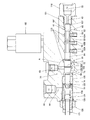
- FIG. 5 is a cross-sectional view seen from the side of the pump device according to the first embodiment of the present invention.
- FIG. 6 is a cross-sectional view of a pump device according to the second embodiment of the present invention.
- the hydraulic drive device 1 is mounted on, for example, a hydraulic excavator and drives a drive target (boom, arm, bucket, or the like). As shown in FIG. 1, the hydraulic drive device 1 includes a hydraulic cylinder 2 as a drive actuator that drives a driven object by supplying and discharging hydraulic oil as a working fluid, and hydraulic oil supplied and discharged to the hydraulic cylinder 2. And a pump device 100 as a drive hydraulic pressure source that supplies hydraulic oil to the hydraulic cylinder 2 through the control valve 3.
- a hydraulic cylinder 2 as a drive actuator that drives a driven object by supplying and discharging hydraulic oil as a working fluid, and hydraulic oil supplied and discharged to the hydraulic cylinder 2.
- a pump device 100 as a drive hydraulic pressure source that supplies hydraulic oil to the hydraulic cylinder 2 through the control valve 3.
- the hydraulic cylinder 2 is expanded and contracted by hydraulic oil guided from the pump device 100 through the control valve 3 to drive the drive target.
- the opening of the control valve 3 is adjusted according to the operator's operation, and the flow rate of the hydraulic oil supplied to the hydraulic cylinder 2 is adjusted.
- FIG. 1 only a single hydraulic cylinder 2 and a control valve 3 for controlling the single hydraulic cylinder 2 are shown, and the other drive actuators and control valves are not shown.
- the hydraulic oil discharged from the pump device 100 is sent to the pump port 31 through the discharge passage 21 and guided to the hydraulic cylinder 2 by the control valve 3 connected to the pump port 31.
- the pump device 100 supplies hydraulic oil to the hydraulic cylinder 2 and changes the discharge capacity according to the tilt angle of the swash plate 11, and the first variable pump according to the supplied control pressure Pcg.
- a tilt actuator 15 that controls the tilt angle of the swash plate 11 in the pump 10, and a regulator (load sensing regulator) 60 that adjusts the control pressure Pcg guided to the tilt actuator 15 according to the differential pressure across the control valve 3;
- a horsepower control regulator 40 that adjusts the control source pressure Pc guided to the regulator 60 in accordance with the discharge pressure P1 of the first pump 10.
- the first pump 10 is, for example, a swash plate type piston pump, and the discharge capacity (pump displacement) is adjusted according to the tilt angle of the swash plate 11.
- the “discharge capacity” refers to the discharge amount of hydraulic oil per rotation of the first pump 10.
- the “discharge flow rate” described later refers to the discharge amount of hydraulic oil per unit time in the first pump 10 and the second pump 16 described later.
- the first pump 10 is driven by the engine 4 as a drive source.
- the first pump 10 sucks hydraulic oil through a suction passage 20 from a tank port 30 connected to a tank (not shown), and discharges hydraulic oil pressurized by a piston (not shown) that reciprocates following the swash plate 11. Discharge into the passage 21.
- the hydraulic oil discharged from the first pump 10 is supplied to the hydraulic cylinder 2 through the control valve 3. Further, part of the hydraulic oil discharged from the first pump 10 is guided to the branch passage 50 branched from the discharge passage 21.
- the branch passage 50 branches into first to third discharge pressure passages 51, 52, and 53, and guides the discharge pressure P1 of the first pump 10 to each of them.
- the first pump 10 includes a cylinder block (not shown) that is rotationally driven by the engine 4, a piston that discharges hydraulic oil that is sucked by reciprocating in a cylinder of the cylinder block, a swash plate 11 that the piston follows, Horsepower control springs 48 and 49 that urge the swash plate 11 in a direction in which the tilt angle increases.
- the tilting actuator 15 drives the swash plate 11 against the urging force of the horsepower control springs 48 and 49 of the first pump 10.
- the tilting actuator 15 may be incorporated in the cylinder block of the first pump 10 or may be provided outside the cylinder block.
- the tilt actuator 15 is extended when the control pressure Pcg adjusted by the horsepower control regulator 40 and the regulator 60 is increased, and the tilt angle of the swash plate 11 is decreased, and the discharge capacity of the first pump 10 is decreased.
- the horsepower control regulator 40 is a 3-port 2-position switching valve.
- a first control pressure passage 55 connected to the regulator 60 is connected to one port of the horsepower control regulator 40.
- the two ports on the other side of the horsepower control regulator 40 are connected to a first discharge pressure passage 51 to which the discharge pressure P1 of the first pump 10 is guided and a low pressure passage 59 connected to the tank.
- the horsepower control regulator 40 includes a high pressure position 40A that communicates the first control pressure passage 55 and the first discharge pressure passage 51, and a low pressure position 40B that communicates the first control pressure passage 55 and the low pressure passage 59.
- a spool (not shown) that moves continuously is provided. The urging force of the horsepower control springs 48 and 49 is applied to one end of the spool of the horsepower control regulator 40.
- a discharge pressure P1 of the first pump 10 guided through the second discharge pressure passage 52 acts on the other end of the spool.
- the spool of the horsepower control regulator 40 moves to a position where the discharge pressure P1 and the urging force of the horsepower control springs 48 and 49 are balanced, and changes the opening degree of the high pressure position 40A and the low pressure position 40B.
- One end of the horsepower control springs 48 and 49 is connected to the spool of the horsepower control regulator 40, and the other end is linked to the swash plate 11 of the first pump 10.
- the length of the horsepower control spring 49 is shorter than that of the horsepower control spring 48.
- the urging force by the horsepower control springs 48 and 49 varies depending on the tilt angle of the swash plate 11 and the position of the spool of the horsepower control regulator 40. Therefore, the urging force acting on the swash plate 11 from the horsepower control springs 48 and 49 is increased stepwise according to the tilt angle of the swash plate 11 and the spool stroke of the horsepower control regulator 40.
- the horsepower control regulator 40 is provided with a horsepower control actuator 41.
- the horsepower control actuator 41 responds to the horsepower control signal pressure Ppw guided from the horsepower control signal pressure port 36 through the horsepower control signal pressure passage 46.
- the hydraulic excavator control system can be switched between the high load mode and the low load mode.
- the horsepower control signal pressure Ppw is lowered in the high load mode while being increased in the low load mode.
- the spool of the horsepower control regulator 40 moves in a direction to switch to the high pressure position 40A. For this reason, the control source pressure Pc increases and the load of the first pump 10 decreases.
- the regulator 60 is a 3-port 2-position switching valve. Connected to the two ports on one side of the regulator 60 are a third discharge pressure passage 53 through which the discharge pressure P1 of the first pump 10 is guided and a first control pressure passage 55 connected to the horsepower control regulator 40, respectively. Is done.
- a second control pressure passage 56 that guides the control pressure Pcg to the tilting actuator 15 is connected to the port on the other side of the regulator 60.
- a throttle 57 is interposed in the second control pressure passage 56, and the pressure fluctuation of the control pressure Pcg guided to the tilting actuator 15 is reduced by the throttle 57.
- a throttle 54 is interposed in the third discharge pressure passage 53, and the pressure fluctuation of the discharge pressure P1 guided to the regulator 60 is reduced by the throttle 54.
- the regulator 60 includes a first position 60A that communicates the first control pressure passage 55 and the second control pressure passage 56, a second position 60B that communicates the third discharge pressure passage 53 and the second control pressure passage 56, and The control spool 61 (refer FIG. 2) which moves continuously between is provided.
- the upstream signal pressure Pps generated on the upstream side of the control valve 3 based on the discharge pressure P1 of the first pump 10 is guided from the signal port 33 through the first signal passage 43 to one end of the control spool 61 of the regulator 60.
- the downstream signal pressure Pls generated on the downstream side of the control valve 3 based on the load pressure of the hydraulic cylinder 2 is guided from the signal port 34 through the second signal passage 44 to the other end of the spool of the regulator 60.
- the other end of the control spool 61 of the regulator 60 is given a biasing force of the LS spring 14 that biases the regulator 60 in the direction to switch the regulator 60 to the first position 60A.
- a specific configuration of the regulator 60 will be described in detail later.
- the pump device 100 includes a constant-capacity type second pump 16 driven by a driving source common to the first pump 10 and a resistor interposed in a pump passage 24 that guides hydraulic oil discharged from the second pump 16.
- a control actuator 70 that adjusts the control pressure Pcg by driving the regulator 60 in accordance with the differential pressure across the resistor 65 (P3-P4), and acts to resist the pressure P3 on the upstream side of the resistor 65
- An auxiliary passage 83 that guides the auxiliary pressure Po to the control actuator 70, a switching valve 80 that is provided in the auxiliary passage 83 and selectively switches between communication and blocking of the auxiliary passage 83, and a switching valve 80 according to an operation input by the operator.
- a controller 90 capable of switching the engine speed and changing the engine speed.
- the second pump 16 is provided side by side with the first pump 10 and is driven by the engine 4 together with the first pump 10.
- a gear pump is used as the second pump 16.
- the second pump 16 sucks the hydraulic oil through the branch suction passage 23 branched from the suction passage 20 and discharges the pressurized hydraulic oil to the pump passage 24.
- the hydraulic oil discharged from the second pump 16 is sent to the pump port 32 through the pump passage 24, and is supplied to a hydraulic drive unit that switches the control valve 3 through a passage (not shown) connected to the pump port 32.
- the resistor 65 is a fixed throttle interposed in the pump passage 24.
- the resistor 65 may have a relief valve or a check valve provided in parallel in addition to the fixed throttle.
- the control actuator 70 is a position where the pressure on the upstream side of the resistor 65 (hereinafter referred to as “upstream pressure”) P3 and the pressure on the downstream side (hereinafter referred to as “downstream pressure”) P4 and the auxiliary pressure Po are balanced. And the regulator 60 is driven according to these pressures. A specific configuration of the control actuator 70 will be described in detail later.
- the auxiliary passage 83 guides the auxiliary pressure Po supplied from the outside of the pump device 100 to the control actuator 70.
- the auxiliary pressure Po is generated by adjusting the pressure of the hydraulic oil discharged from the second pump 16 by an adjusting mechanism outside the pump device 100.
- the switching valve 80 is a 2-port 2-position electromagnetic switching valve (ON-OFF valve).
- the changeover valve 80 communicates with the auxiliary passage 83 to supply the auxiliary pressure Po to the control actuator 70, and the shutoff position 80B interrupts the supply of the auxiliary pressure Po to the control actuator 70 through the auxiliary passage 83.
- the controller 90 includes a microcomputer having a CPU (Central Processing Unit), ROM (Read Only Memory), RAM (Random Access Memory), and I / O interface (input / output interface).
- the RAM stores data in the processing of the CPU
- the ROM stores a control program of the CPU in advance
- the I / O interface is used for input / output of information with the connected device.
- the controller 90 may be composed of a plurality of microcomputers.
- the controller 90 is programmed so as to be able to execute at least processing necessary for executing control according to each embodiment or modification.
- the controller 85 may be configured as a single device, or may be divided into a plurality of devices, and each control in each embodiment may be configured to be distributedly processed by the plurality of devices.
- the switching valve 80 When a current is supplied from the controller 90 to the solenoid 82, the switching valve 80 becomes the communication position 80A and opens the auxiliary passage 83. As a result, the auxiliary pressure Po is guided to the control actuator 70 through the auxiliary passage 83.
- the switching valve 80 assumes the blocking position 80B by the biasing force of the biasing spring 81 and blocks the auxiliary passage 83.
- the supply of the auxiliary pressure Po to the control actuator 70 is cut off, and a third pressure chamber 79 of the control actuator 70 described later communicates with the tank and becomes the tank pressure.
- the control actuator 70 selectively receives the auxiliary pressure Po introduced from the auxiliary passage 83 in addition to the differential pressure across the resistor 65 (P3-P4), and the control piston 71 causes the differential pressure across the resistor 65 (P3-P3).
- the driving force is applied to the regulator 60 by moving to a position where the P4) and the auxiliary pressure Po are balanced.
- the control spool 61 of the regulator 60 has an LS differential pressure (Pps ⁇ Pls) generated before and after the control valve 3 and a biasing force of the LS spring 14 acting on the other end of the control spool 61, As the applied driving force, the differential pressure across the resistor 65 (P3-P4) and the auxiliary pressure Po act.
- the control spool 61 of the regulator 60 moves to a position where the LS differential pressure (Pps-Pls), the differential pressure across the resistor 65 (P3-P4), the auxiliary pressure Po, and the biasing force of the LS spring 14 are balanced.
- the opening degree of the first position 60A and the second position 60B of the regulator 60 is changed.
- the regulator 60, the control actuator 70, and the switching valve 80 are provided in a common housing 101, respectively.
- a spool hole 102 for accommodating the control spool 61 of the regulator 60 and a cylinder hole 103 into which the control piston 71 of the control actuator 70 is slidably inserted are formed coaxially.
- the housing 101 further includes a first pilot chamber 107 into which the upstream signal pressure Pps of the control valve 3 is guided and a second pilot chamber 108 into which the downstream signal pressure Pls of the control valve 3 is guided.
- the second pilot chamber 108, the cylinder hole 103, the spool hole 102, and the first pilot chamber 107 are provided in this order along the axial direction.
- control spool 61 of the regulator 60 and the control piston 71 of the control actuator 70 are integrally formed side by side on the same axis. Not limited to this, the control spool 61 and the control piston 71 may be formed separately and linked to each other.
- the control spool 61 of the regulator 60 is inserted into the spool hole 102 so as to be movable in the axial direction.
- the control spool 61 has first, second, and third land portions 62, 63, and 64 that are aligned in the axial direction and slide in the spool hole 102.
- the first, second, and third land portions 62, 63, and 64 are formed on the same axis.
- a first annular groove 62 ⁇ / b> A that opens to the outer peripheral surface of the control spool 61 is formed between the first land portion 62 and the second land portion 63.
- a second annular groove 63A that opens to the outer peripheral surface of the control spool 61 is formed. Further, the second land portion 63 is formed with a third annular groove 63B on the outer periphery, which communicates the second control pressure passage 56 and a counter hole 115 described later regardless of the position of the control spool 61.
- the cylinder hole 103 includes a first cylinder hole 104 having an inner diameter larger than the inner diameter of the spool hole 102 and a second cylinder hole having an inner diameter larger than the inner diameter of the first cylinder hole 104. 105. Between the first cylinder hole 104 and the second cylinder hole 105, a first cylinder step portion 106A that is an annular step portion is formed. Between the 1st cylinder hole 104 and the spool hole 102, the 2nd cylinder step part 106B which is a cyclic
- the control piston 71 is connected to the control spool 61 and is slidably inserted into the first cylinder hole 104.
- the control piston 71 is connected to the first piston part 72 and slidably inserted into the second cylinder hole 105.
- the second piston portion 73 and the first piston portion 72 in the second piston portion 73 are connected to the second piston portion 73 on the opposite side in the axial direction and are formed with an outer diameter smaller than that of the second piston portion 73. It has the 3rd piston part 74 and the piston step part 75 (refer FIG. 3) which is an annular
- the third piston portion 74 is slidably supported by a guide sleeve 125 described later housed in the second pilot chamber 108.
- the inside of the cylinder hole 103 includes a first pressure chamber 77 formed between the first piston portion 72 and the second cylinder step portion 106 ⁇ / b> B by the control piston 71, and a second pilot chamber 108.
- a second pressure chamber 78 formed between the guide sleeve 125 and the second piston portion 73 provided in the second piston chamber 73 and a third pressure chamber 79 formed between the second piston portion 73 and the first cylinder step portion 106A. And partitioned.
- the first pilot chamber 107 communicates with the spool hole 102 and opens on the surface of the housing 101 as shown in FIG.
- the second pilot chamber 108 communicates with the cylinder hole 103 and opens on the surface of the housing 101.
- the opening to the surface of the housing 101 is sealed by the first plug 110.
- the first plug 110 is formed with a signal port 33 and a first signal passage 43 that guide the upstream signal pressure Pps of the control valve 3 to the first pilot chamber 107.
- the second pilot chamber 108 includes an LS spring 14, an adjuster 120 that adjusts the biasing force of the LS spring 14, a guide sleeve 125 that faces the cylinder hole 103, and a second pilot chamber 108 that seals the opening of the second pilot chamber 108. Plug 126 is accommodated.
- the adjuster 120 includes an adjuster rod 121 that is screwed into the second plug 126, a spring receiver 123 that is attached to the third piston portion 74 of the control piston 71, and a spring receiver that is slidably accommodated inside the second plug 126. 124.
- the coiled LS spring 14 is interposed between the spring receiver 123 and the spring receiver 124 by being compressed. By changing the screwing position of the adjuster rod 121, the urging force of the LS spring 14 is adjusted.
- the housing 101 further includes a downstream signal port 34 and a second signal path 44 through which the downstream signal pressure Pls of the control valve 3 is guided, and an auxiliary path 83 through which the auxiliary pressure Po is guided.
- the downstream signal pressure Pls is guided to the second pilot chamber 108 through the downstream signal port 34 and the second signal passage 44.
- the housing 101 has a third discharge pressure passage 53 through which the discharge pressure of the first pump 10 is guided as an introduction passage that opens from the radial direction to the spool hole 102 and guides hydraulic oil to the spool hole 102, and the tilt actuator 15.
- a second control pressure passage 56 through which the control pressure Pcg supplied to the first pressure control passage is guided, a first control pressure passage 55 communicating with the horsepower control regulator 40, and a downstream pressure passage 95 through which the downstream pressure P4 of the resistor 65 is guided. Further formed.
- these passages are collectively referred to simply as “introduction passages”.
- opposed holes 115 corresponding to the introduction passages 53, 55, 56, 95 are formed at positions facing the openings of the introduction passages 53, 55, 56, 95 across the center of the spool hole 102.
- the upstream signal pressure Pps acts on the axial end surface of the first land portion 62 of the control spool 61, and exerts a driving force that moves the control spool 61 and the control piston 71 leftward in FIG.
- the downstream signal pressure Pls acts on the axial end surface of the third piston portion 74 of the control piston 71 in the control actuator 70 directly or via the spring receiver 123, and moves the control piston 71 and the control spool 61 rightward in FIG. Demonstrate the driving force.
- the pressure receiving area of the upstream signal pressure Pps and the pressure receiving area of the downstream signal pressure Pls are configured to be equal to each other.
- the pressure receiving area of the upstream signal pressure Pps corresponds to the cross-sectional area of the first land portion 62 of the control spool 61 on which the upstream signal pressure Pps acts.
- the pressure receiving area of the downstream signal pressure Pls corresponds to the cross-sectional area of the third piston portion 74 of the control piston 71 on which the downstream signal pressure Pls acts. That is, the cross-sectional area of the first land portion 62 and the cross-sectional area of the third piston portion 74 of the control spool 61 are formed to be equal to each other.
- the second control pressure passage 56 When the LS differential pressure (Pps-Pls) between the upstream signal pressure Pps and the downstream signal pressure Pls is small and the LS spring 14 is extended, as shown in FIG. 2, the second control pressure passage 56 has a second annular groove. While communicating with the first control pressure passage 55 through 63A, communication with the third discharge pressure passage 53 is blocked by the second land portion 63 (first position 60A). When the LS differential pressure (Pps ⁇ Pls) is large and the LS spring 14 is contracted, the second control pressure passage 56 communicates with the third discharge pressure passage 53 through the first annular groove 62A as shown in FIG. At the same time, the communication with the first control pressure passage 55 is blocked by the second land portion 63 (second position 60B).
- the downstream pressure passage 95 is connected to the first pressure chamber 77 as shown in FIG.
- a downstream pressure P4 of the resistor 65 is guided to the first pressure chamber 77 through the downstream pressure passage 95.
- the downstream pressure P4 guided to the first pressure chamber 77 acts on the first piston portion 72 of the control piston 71 to switch the regulator 60 to the second position 60B (left direction in FIG. 1, left direction in FIG. 3).
- the driving force that moves the control piston 71 to the center is exhibited.
- the upstream pressure passage 94 is connected to the second pressure chamber 78.
- the upstream pressure P 3 of the resistor 65 is guided to the second pressure chamber 78 through the upstream pressure passage 94.
- the upstream pressure P3 guided to the second pressure chamber 78 acts on the second piston portion 73 of the control piston 71 to change the regulator 60 to the first position 60A (right direction in FIG. 1, right direction in FIG. 3).
- the driving force that moves the control piston 71 to the center is exhibited.
- An auxiliary passage 83 is connected to the third pressure chamber 79.
- the auxiliary pressure Po is selectively guided to the third pressure chamber 79 through the auxiliary passage 83.
- the switching valve 80 is in the communication position 80A, the auxiliary pressure Po is supplied to the third pressure chamber 79 through the auxiliary passage 83.
- the switching valve 80 is in the cutoff position 80B, the supply of the auxiliary pressure Po to the third pressure chamber 79 through the auxiliary passage 83 is shut off, and the third pressure chamber 79 communicates with the tank.
- auxiliary driving force The auxiliary pressure Po guided to the third pressure chamber 79 acts on the piston step 75 to drive the control piston 71 in a direction in which the regulator 60 switches to the second position 60B (hereinafter referred to as “auxiliary driving force”). ). That is, the auxiliary driving force supplements the driving force of the control piston 71 generated by the downstream pressure P4 of the resistor 65 and acts against the driving force of the control piston 71 generated by the upstream pressure P3 of the resistor 65. It is. Therefore, the auxiliary pressure Po apparently acts on the control piston 71 so that the driving force (hereinafter referred to as “differential pressure driving force”) generated by the differential pressure across the resistor 65 (P3-P4) is reduced. .
- driving force hereinafter referred to as “differential pressure driving force”
- the switching valve 80 includes a switching spool 85 that selectively switches between the communication position 80A and the cutoff position 80B, and a biasing spring 81 that biases the switching spool 85 so as to take the cutoff position 80B. And a solenoid 82 that exhibits a driving force that resists the biasing force of the biasing spring 81 when energized.
- the housing 101 has a switching spool hole 109 into which the switching spool 85 of the switching valve 80 is slidably inserted, and a first communication path 83A that communicates with the switching spool hole 109 and guides the auxiliary pressure Po from the outside of the pump device 100.
- a second communication passage 83B that communicates with the switching spool hole 109 and communicates with the third pressure chamber 79; and a discharge passage 84 that communicates with the switching spool hole 109 and guides hydraulic oil to the tank port 30 (see FIG. 1). It is formed.
- the first communication passage 83A and the second communication passage 83B constitute a part of the auxiliary passage 83.
- the switching spool 85 of the switching valve 80 has first and second switching land portions 86 and 87 that slide in the switching spool hole 109.
- the switching spool 85 is provided with an annular groove 88 that opens to the outer peripheral surface and is formed between the first switching land portion 86 and the second switching land portion 87.
- the biasing spring 81 is interposed between the bottom of the switching spool hole 109 and the switching spool 85 in a compressed state.
- the switching spool 85 is urged by the urging force of the urging spring 81 as shown in FIG. 5, and the communication between the first communication path 83A and the second communication path 83B is established. Is blocked by the first switching land portion 86 (blocking position 80B).
- the switching spool 85 moves against the biasing force of the biasing spring 81 by the driving force of the solenoid 82.
- the first communication passage 83A and the second communication passage 83B communicate with each other through the annular groove 88, and the auxiliary pressure is guided to the third pressure chamber 79 (communication position 80A).
- the horsepower control regulator 40 controls the discharge capacity of the first pump 10 so as to keep the discharge pressure P1 of the first pump 10 constant
- the regulator 60 controls the differential pressure (LS) across the control valve 3 by the regulator 60.
- Load control (LS control) for controlling the discharge capacity of the first pump 10 so as to keep the (differential pressure) constant
- the discharge flow rate for controlling the discharge capacity of the first pump 10 according to the pump speed (engine speed). Control.
- the regulator 60 adjusts the control pressure Pcg according to the control source pressure Pc adjusted by the horsepower control regulator 40.
- the discharge capacity of the first pump 10 is controlled by load control without horsepower control.
- the discharge capacity of the first pump 10 is controlled by horsepower control. Therefore, while controlling the discharge capacity of the first pump 10 so as to keep the discharge pressure P1 of the first pump 10 within a certain range by the horsepower control, the second pressure so as to keep the LS differential pressure of the control valve 3 constant by the load control.
- the discharge capacity of one pump 10 can also be controlled.
- the control pressure Pc guided to the regulator 60 increases, so that the control pressure Pcg adjusted by the regulator 60 increases, so that the tilt actuator 15 reduces the tilt angle of the swash plate 11 of the first pump 10. To drive. Therefore, when the discharge pressure P1 of the first pump 10 increases, the discharge capacity of the first pump 10 decreases.
- the horsepower control regulator 40 adjusts the control source pressure Pc guided to the regulator 60 so that the driving force generated by the discharge pressure P1 and the biasing force of the horsepower control springs 48 and 49 are balanced.
- the horsepower control regulator 40 operates so as to increase the control source pressure Pc as the discharge pressure P1 increases due to the increase in the pump rotation speed, thereby increasing the control pressure Pcg, and decreases the discharge capacity of the first pump 10. Further, the horsepower control regulator 40 operates so as to decrease the control source pressure Pc and decrease the control pressure Pcg as the discharge pressure P1 decreases due to a decrease in the pump rotation speed, and increases the discharge capacity of the first pump 10.
- the horsepower control regulator 40 discharges the first pump 10 so as to cancel the change in the discharge flow rate (supply flow rate) of the first pump 10 accompanying the change in the pump rotation speed even when the pump rotation speed changes. Increase or decrease capacity. Therefore, the load (power) of the first pump 10 is adjusted to be substantially constant regardless of the pump rotation speed.
- the regulator 60 adjusts the control pressure Pcg guided to the tilting actuator 15 so that the LS differential pressure (Pps ⁇ Pls) and the urging force of the LS spring 14 are balanced.
- the regulator 60 operates so as to increase the discharge capacity of the first pump 10 by decreasing the control pressure Pcg and increase the LS differential pressure (Pps-Pls).
- the regulator 60 increases the control pressure Pcg to decrease the discharge capacity of the first pump 10 and operates so that the LS differential pressure (Pps ⁇ Pls) decreases.
- the regulator 60 controls the discharge capacity of the first pump 10 so that the LS differential pressure (Pps ⁇ Pls) becomes substantially constant even when the load on the hydraulic cylinder 2 increases or decreases.
- the hydraulic cylinder 2 can be driven at the same speed regardless of the work load, and the controllability of the hydraulic cylinder 2 can be improved.
- the drive speed (supply flow rate) of the hydraulic cylinder 2 can be controlled only by the opening degree (position) of the control valve 3, and the change in the speed of the hydraulic cylinder 2 due to the fluctuation of the work load can be prevented.
- the discharge flow rate control is performed by driving the regulator 60 by the control actuator 70 in accordance with the differential pressure (P3-P4) across the resistor 65 to which the hydraulic oil discharged from the second pump 16 is guided.
- the differential pressure across the resistor 65 increases.
- the differential pressure (P3-P4) of the resistor 65 increases from the state in which the forces acting on the control actuator 70 are balanced, that is, when the upstream pressure P3 becomes relatively large, the control actuator 70 is switched to the first position 60A.
- the control spool 61 of the regulator 60 is driven in the changing direction (right direction in FIG. 1).
- the communication opening degree between the first control pressure passage 55 and the second control pressure passage 56 increases, so that the control pressure Pcg guided to the tilting actuator 15 is the control source pressure Pc adjusted by the horsepower control regulator 40.
- the tilt actuator 15 drives the swash plate 11 of the first pump 10 so that the tilt angle increases, and the discharge capacity of the first pump 10 increases.
- the discharge flow rate of the first pump 10 is controlled to increase in proportion to the increase in the engine 4 rotation speed.
- auxiliary pressure supply state the state in which the switching valve 80 is in the communication position 80A and the auxiliary pressure Po is guided to the third pressure chamber 79 of the control actuator 70 through the auxiliary passage 83.
- auxiliary pressure cutoff state A state in which 80 is the cutoff position 80B and the auxiliary pressure Po is not guided to the third pressure chamber 79 is referred to as an “auxiliary pressure cutoff state”.
- the auxiliary pressure Po introduced through the auxiliary passage 83 is supplied to the third pressure chamber 79 of the control actuator 70 and provides an auxiliary driving force against the upstream pressure P3 of the resistor 65 to the piston step 75 of the control actuator 70.
- the auxiliary pressure Po acts on the control piston 71 of the control actuator 70 so as to compensate the downstream pressure P4 of the resistor 65, and apparently acts so that the differential pressure across the resistor 65 (P3-P4) becomes small. To do.
- the control pressure Pcg guided to the tilting actuator 15 increases, and the discharge flow rate of the first pump 10 is smaller than in the auxiliary pressure cutoff state when the pump rotation speed is the same. Become.
- the control pressure Pcg is lower than in the auxiliary pressure supply state, and thus the discharge flow rate of the first pump 10 is increased.
- the controller 90 switches the position of the switching valve 80 and changes the rotational speed of the engine 4 in accordance with the operator's operation input.
- the controller 90 changes the engine speed in accordance with the switching of the switching valve 80 based on the operator's operation input, thereby controlling the operation of the pump device 100 in the “normal mode” and the “energy saving mode”. Switch between the two control states.
- the engine speed is maintained at a relatively high first speed, and the switching valve 80 is switched to the communication position 80A.
- the auxiliary pressure Po is guided to the control actuator 70, and the discharge capacity of the first pump 10 is set to a relatively small state.
- the controller 90 maintains the engine speed at the second speed lower than the first speed, and the switching valve 80 is switched to the shut-off position 80B to supply the auxiliary pressure Po to the control actuator 70. Blocked.
- the area of the piston step portion 75 which is the pressure receiving area of the auxiliary pressure Po, is set so that the auxiliary driving force corresponds to a decrease in the differential pressure driving force accompanying switching of the engine speed. More specifically, when the engine speed is switched from the first speed to the second speed, the discharge flow rate of the second pump 16 decreases and the differential pressure driving force decreases.
- the auxiliary driving force is a driving force that acts in a direction against the differential pressure driving force. Accordingly, simultaneously with switching the engine speed from the first speed to the second speed, the supply of the auxiliary pressure Po is cut off, so that the auxiliary driving force does not act as the differential pressure driving force decreases. There is almost no change in the position of. Thereby, in the energy saving mode, the supply flow rate to the hydraulic cylinder 2 can be maintained at the same level as that in the normal mode.
- the same discharge flow rate (supply flow rate) as that in the normal mode can be ensured despite the engine speed lower than that in the normal mode, and the drive speed equivalent to that in the normal mode can be realized. Therefore, the energy consumption of the pump device 100 can be suppressed.
- the discharge flow rate can be easily adjusted by changing the engine rotation speed. Therefore, in the normal mode, the supply flow rate to the hydraulic cylinder 2 can be adjusted with high accuracy.
- control pressure Pcg increases based on the discharge pressure P1 of the first pump 10 guided through the third discharge pressure passage 53, and the tilt actuator 15 causes the swash plate of the first pump 10 so that the tilt angle decreases. 11 is driven. Accordingly, since the discharge capacity of the first pump 10 decreases due to the decrease in the engine speed, the driving speed of the hydraulic cylinder 2 decreases according to the engine speed.
- the pump device 100 it is possible to switch between maintaining or decreasing the driving force of the control actuator 70 as the engine speed decreases in accordance with the operation input of the operator. Therefore, in the pump apparatus 100, the change rate of the discharge flow rate with respect to the change of the rotation speed can be changed.
- the auxiliary pressure Po acts against the upstream pressure P3 of the resistor 65, and acts to apparently reduce the differential pressure across the resistor 65 (P3-P4).
- the auxiliary pressure P Azure acts against the downstream pressure P4 of the resistor 65, in other words, acts to supplement the upstream pressure P3, and apparently the front-to-back differential pressure (P3-P4) is apparent. You may make it act so that it may enlarge.
- the control pressure Pcg adjusted by the regulator 60 is changed by switching the supply and shutoff of the auxiliary pressure Po by the switching valve 80, so that the discharge of the first pump 10 is performed even with the same load. The flow rate can be changed.
- the rotational speed of the engine 4 in the energy saving mode, the rotational speed of the engine 4 is reduced and the supply of the auxiliary pressure Po against the upstream pressure P3 of the resistor 65 is shut off.
- the rotational speed of the engine 4 is increased or decreased, or the auxiliary pressure Po is against the upstream pressure P3 of the resistor 65 or is against the downstream pressure P4.
- the pump device 100 may be configured to supply the auxiliary pressure Po that resists the downstream pressure P4 of the resistor 65 when the rotational speed of the engine 4 is reduced. In this case, the same effect as the above energy saving mode is produced.
- the rotational speed change of the engine 4, the switching of the auxiliary pressure P réelle, and the direction of action of the auxiliary pressure Po can be arbitrarily configured according to needs.
- the switching valve 80 is an ON-OFF valve that selectively switches between communication and blocking of the auxiliary passage 83.
- the switching valve 80 opens the auxiliary passage 83 with a communication opening degree (communication flow passage area) corresponding to the energization amount to the solenoid 82, and controls the magnitude of the auxiliary pressure Po guided to the control actuator 70.
- An electromagnetic proportional valve may be used.
- the controller 90 may acquire the engine speed and energize the solenoid 82 of the switching valve 80 with an energization amount corresponding to the engine speed.
- the switching valve 80 when the switching valve 80 is switched so as to cut off the supply of the auxiliary pressure Po to the control actuator 70 as the engine speed decreases, the differential pressure driving force decreases due to the decrease in engine speed. Auxiliary driving force acting against the differential pressure driving force does not work. Therefore, the driving amount of the regulator 60 by the control actuator 70 does not change before and after the switching valve 80 is switched, and the tilt angle of the swash plate 11 does not change. For this reason, even if the engine speed changes, the discharge flow rate of the first pump 10 hardly changes.
- the control actuator 70 causes the control pressure Pcg due to a decrease in the differential pressure driving force based on the decrease in the engine speed.
- the regulator 60 is driven so as to rise, and the tilt angle of the swash plate 11 becomes small.
- the opposed hole 115 is formed at a position facing the opening of each introduction passage 53, 55, 56, 95, the pressure balance of the hydraulic oil acting on the control spool 61 is maintained, and the control spool The slidability of 61 can be improved.
- the regulator 60, the control actuator 70, and the switching valve 80 are provided in the common housing 101, respectively.
- the switching valve 80 is accommodated in a valve housing 201 that is detachably attached to the housing 101 that accommodates the control spool 61 of the regulator 60.
- the pump device 200 further includes a valve housing 201 that is detachably attached to the housing 101 that houses the control spool 61 of the regulator 60 and that houses the switching valve 80.
- the valve housing 201 is detachably attached to the housing 101 with bolts (not shown).
- the solenoid 82 is attached to the valve housing 201.
- the valve housing 201 has a switching spool hole 109, a first communication path 183 A that opens to the surface of the valve housing 201 and communicates with the switching spool hole 109 and guides the auxiliary pressure Po from the outside of the pump device 200, and the switching spool hole 109.
- a second communication passage 183B that leads the auxiliary pressure to the third pressure chamber 79 and a discharge passage 189 that communicates with the switching spool hole 109 and communicates with the tank are formed.
- the housing 101 further includes a connection passage 83C that connects the first communication passage 183A of the valve housing 201 and the third pressure chamber 79, and a tank connection passage 83D that connects the discharge passage 189 and the tank port 30.
- the switching valve 80 When the switching valve 80 is in the communication position 80A shown in FIG. 6, the auxiliary pressure Po is guided to the third pressure chamber 79 through the first communication passage 183A, the switching spool hole 109, the second communication passage 183B, and the connection passage 83C. It is burned.
- the switching valve 80 is in the cutoff position 80B, the auxiliary pressure Po is guided to the tank port 30 through the first communication path 183A, the switching spool hole 109, the discharge path 189, and the tank connection path 83D.
- valve housing 201 that houses the switching valve 80 as a separate body from the housing 101
- the switching valve 80, the first communication path 183A, the second communication path 183B, and the auxiliary path 83 for the regulator 60 are provided.
- the degree of freedom in layout can be improved.
- the valve housing 201 having a different layout such as the formed switching spool hole 109
- the direction of the solenoid 82 can be arbitrarily set according to the hydraulic excavator on which the pump device 200 is mounted. Thereby, it can prevent that the driving force of the switching spool 85 by the solenoid 82 falls under the influence of gravity by arrange
- the first communication path 183A and the second communication path 183B formed in the valve housing 201 can be laid out at an arbitrary position.
- the hydraulic piping connected to the signal ports 33 and 34 for respectively leading the upstream signal pressure Pps and the downstream signal pressure Pls of the control valve 3 can also have an arbitrary layout. Thereby, the pump apparatus 200 can be easily installed in a place where the installation space is limited, such as in the engine room.
- the switching valve 80 is provided in the valve housing 201 separate from the housing 101, the layout of the auxiliary passage 83, the first communication passage 183A, and the second communication passage 183B for guiding the solenoid 82 and the auxiliary pressure Po is provided.
- the degree of freedom is improved. Therefore, the driving direction of the solenoid 82 can be prevented from being directed in the vertical direction, and the degree of freedom in the layout of the hydraulic piping can be improved, so that the mounting capability of the pump device 200 on a hydraulic excavator or the like can be improved.
- LS differential pressure front-rear differential pressure
- the constant capacity type second pump 16 the resistor 65 provided in the pump passage 24 through which the hydraulic oil discharged from the second pump 16 is guided, and the differential pressure across the resistor 65 (P3-P4)
- the control actuator 70 that operates in response to the regulator 60 so as to decrease the control pressure Pcg according to the increase in the differential pressure across the resistor 65 (P3-P4), and the upstream pressure P3 and the downstream pressure P4 of the resistor 65.
- An auxiliary passage 83 that guides the auxiliary pressure Po acting on the control actuator 70 to the control actuator 70 against one of the above, and a switching valve 80 that switches between supply and interruption of the auxiliary pressure Po to the control actuator 70 through the auxiliary passage 83.
- a controller 90 that switches the switching valve 80 and switches the rotational speed of the drive source (engine 4) between a first rotational speed and a second rotational speed smaller than the first rotational speed, and a control actuator 70 Are the differential pressure driving force generated by receiving the differential pressure across the resistor 65 and the auxiliary driving force generated by receiving the auxiliary pressure Po.
- the pressure receiving area of the control piston 71 that has the control piston 71 that moves so that the auxiliary pressure Po acts is that the rotational speed of the drive source (engine 4) is between the first rotational speed and the second rotational speed.
- the auxiliary driving force is set so as to correspond to the amount of change in the differential pressure driving force accompanying the switching.
- the driving force of the control actuator 70 is changed as the rotational speed of the drive source (engine 4) decreases by switching between supply and interruption of the auxiliary pressure Po when the rotational speed of the drive source (engine 4) changes. Or can be switched. Therefore, in the pump devices 100 and 200, the change rate of the discharge flow rate with respect to the change of the rotation speed can be changed.
- the regulator 60 further includes a housing 101 that accommodates the control spool 61.
- the housing 101 has a spool hole 102 into which the control spool 61 is movably inserted in the axial direction, and a radial direction.
- a counter hole 115 is formed at a position opposite to the opening of the introduction passage (third discharge pressure passage 53, first control pressure passage 55, second control pressure passage 56, downstream pressure passage 95) across the center.
- the control spool 61 is an annular shape that guides hydraulic oil from the introduction passage (the third discharge pressure passage 53, the first control pressure passage 55, the second control pressure passage 56, and the downstream pressure passage 95). It has grooves (first annular groove 62A, second annular groove 63A, third annular groove 63B), and opposed hole 115 is an annular groove (first annular groove 62A, second annular groove regardless of the position of control spool 61). 63A and the third annular groove 63B).
- the pump device 200 further includes a valve housing 201 that is detachably attached to the housing 101 that houses the control spool 61 of the regulator 60 and that houses the switching valve 80.
- the driving direction of the switching valve 80 can be prevented from matching the vertical direction.
- the pressure receiving area on which the upstream pressure Pps of the control valve 3 acts and the pressure receiving area on which the downstream pressure Pls acts are set to be equal to each other. .
- the auxiliary pressure Po acts on the control actuator 70 so as to resist the upstream pressure P3 of the resistor 65, and the pressure receiving area of the control piston 71 on which the auxiliary pressure Po acts is the drive source (
- the auxiliary driving force is set so as to correspond to the amount of decrease in the differential pressure driving force when the engine 4) is switched from the first rotational speed to the second rotational speed.
- the differential pressure driving force exerted by the differential pressure across the resistor 65 decreases due to the decrease in the discharge flow rate of the second pump 16 due to the decrease in the rotational speed of the drive source (engine 4).
- the switching valve 80 is switched so as to cut off the supply of the auxiliary pressure Po to the control actuator 70 as the rotational speed of the drive source (engine 4) decreases, the differential pressure is reduced due to the decrease in the rotational speed of the drive source (engine 4).
- the driving force decreases, the auxiliary driving force acting against the differential pressure driving force stops working. Therefore, the driving amount of the regulator 60 by the control actuator 70 does not change before and after the switching valve 80 is switched, and the tilt angle of the swash plate 11 does not change.
- the switching valve 80 is switched so as to supply the auxiliary pressure Po to the control actuator 70 as the rotational speed of the drive source (engine 4) decreases, the differential pressure drive based on the decrease in the rotational speed of the drive source (engine 4).
- the control actuator 70 drives the regulator 60 so that the control pressure Pcg increases, and the tilt angle of the swash plate 11 decreases.
- the pump apparatus 100 it is possible to switch between maintaining or decreasing the driving force of the control actuator 70 as the rotational speed of the driving source (engine 4) decreases. Therefore, in the pump devices 100 and 200, the change rate of the discharge flow rate with respect to the change of the rotation speed can be changed.
Landscapes
- Engineering & Computer Science (AREA)
- General Engineering & Computer Science (AREA)
- Mechanical Engineering (AREA)
- Physics & Mathematics (AREA)
- Fluid Mechanics (AREA)
- Mining & Mineral Resources (AREA)
- Civil Engineering (AREA)
- Structural Engineering (AREA)
- Computer Hardware Design (AREA)
- Fluid-Pressure Circuits (AREA)
- Operation Control Of Excavators (AREA)
- Control Of Positive-Displacement Pumps (AREA)
Abstract
ポンプ装置(100)は、可変容量型の第1ポンプ(10)における斜板(11)の傾転角度を制御する傾転アクチュエータ(15)と、制御圧(Pcg)を制御弁(3)の前後差圧に応じて調整するレギュレータ(60)と、定容量型の第2ポンプ(16)から吐出される作動油が導かれる抵抗器(65)の前後差圧に応じてレギュレータ(60)を駆動する制御アクチュエータ(70)と、を備え、制御アクチュエータ(70)では、抵抗器(65)の上流圧(P3)に抗する補助圧(Po)が作用する制御ピストン(71)の受圧面積は、駆動源の回転数が第1回転数から第2回転数へ切り換えられるのに伴う差圧駆動力の低下量に補助駆動力が相当するように設定される。
Description
本発明は、ポンプ装置に関するものである。
JP2008-291731Aには、斜板の傾転角度に応じて油圧回路に供給されるポンプ吐出量が可変となる第1のポンプと、供給される制御圧力の上昇に応じて斜板の傾転角度を減少させる傾転アクチュエータと、油圧回路の負荷圧に応じて制御圧力を調整するレギュレータと、第1のポンプと連動する第2のポンプと、第2のポンプの吐出回路に介装したオリフィスと、オリフィスの前後差圧の上昇に応じてレギュレータにより調整される制御圧を減じるように駆動するアクチュエータと、を備えるポンプ装置が開示されている。
JP2008-291731Aに開示されるようなロードセンシング制御されるポンプ装置では、第1、第2ポンプを駆動する駆動源の回転数が低下すると、第2ポンプの吐出流量が減少し、オリフィス(抵抗器)の前後差圧が低下する。これにより、アクチュエータ(制御アクチュエータ)は、制御圧が上昇するようにレギュレータを駆動するため、傾転アクチュエータは斜板の傾転角度を減少させ、第1ポンプの吐出量は減少する。このように、JP2008-291731Aのポンプ吐出量制御装置では、駆動源の回転数が低下すると第1ポンプの吐出流量が減少して、駆動対象を駆動する駆動アクチュエータの速度は低下する。
ここで、例えば作業者が異なる場合など、駆動源の回転数に対して求められる駆動アクチュエータの駆動速度が異なる場合がある。つまり、ポンプ装置には、回転数の低下に応じて駆動速度を低下させる場合と、回転数が低下するにも関わらず駆動速度をほとんど低下させずに維持させる場合と、の両方の機能が求められることがある。
本発明は、回転数の変化に対する吐出流量の変化割合を変更できるポンプ装置を提供することを目的とする。
本発明のある態様によれば、駆動対象を駆動する駆動アクチュエータに制御弁を通じて作動流体を供給するポンプ装置であって、駆動アクチュエータに作動流体を供給し斜板の傾転角度に応じて吐出容量が変化する可変容量型の第1ポンプと、供給される制御圧に応じて第1ポンプにおける斜板の傾転角度を制御する傾転アクチュエータと、制御弁の上流側の圧力と下流側の圧力との前後差圧に応じて移動する制御スプールによって制御圧を調整するレギュレータと、第1ポンプと共通の駆動源によって駆動される定容量型の第2ポンプと、第2ポンプから吐出される作動流体が導かれるポンプ通路に設けられる抵抗器と、抵抗器の前後差圧の上昇に応じて制御圧を低下させるようにレギュレータを駆動する制御アクチュエータと、抵抗器の上流側圧力及び下流側圧力の一方に抗するように制御アクチュエータに作用する補助圧を制御アクチュエータへ導く補助通路と、補助通路を通じた制御アクチュエータへの補助圧の供給と遮断とを切り換える切換弁と、切換弁を切り換えると共に駆動源の回転数を第1回転数と当該第1回転数よりも小さい第2回転数との間で切り換えるコントローラと、を備え、制御アクチュエータは、抵抗器の前後差圧を受けることにより生じる差圧駆動力と補助圧を受けることにより生じる補助駆動力とが釣り合うように移動する制御ピストンを有し、補助圧が作用する制御ピストンの受圧面積は、駆動源の回転数が第1回転数と第2回転数との間で切り換えられるのに伴う差圧駆動力の変化量に補助駆動力が相当するように設定される。
(第1実施形態)
図面を参照して、本発明の第1実施形態に係るポンプ装置100及びこれを備える油圧駆動装置1について説明する。
図面を参照して、本発明の第1実施形態に係るポンプ装置100及びこれを備える油圧駆動装置1について説明する。
油圧駆動装置1は、例えば油圧ショベルに搭載され、駆動対象(ブーム,アーム,又はバケット等)を駆動する。油圧駆動装置1は、図1に示すように、作動流体としての作動油が給排されることにより駆動対象を駆動する駆動アクチュエータとしての油圧シリンダ2と、油圧シリンダ2に給排される作動油の流れを制御する制御弁3と、制御弁3を通じて油圧シリンダ2に作動油を供給する駆動油圧源としてのポンプ装置100と、を備える。
油圧シリンダ2は、制御弁3を通じてポンプ装置100から導かれる作動油によって伸縮作動して、駆動対象を駆動する。制御弁3は、作業者の操作に応じて開度が調整され、油圧シリンダ2に供給される作動油の流量を調整する。図1では、単一の油圧シリンダ2及びこれを制御する制御弁3のみを図示し、その他の駆動アクチュエータ及び制御弁は図示を省略する。
ポンプ装置100から吐出される作動油は、吐出通路21を通じてポンプポート31に送られ、ポンプポート31に接続する制御弁3によって油圧シリンダ2に導かれる。
ポンプ装置100は、油圧シリンダ2に作動油を供給し斜板11の傾転角度に応じて吐出容量が変化する可変容量型の第1ポンプ10と、供給される制御圧Pcgに応じて第1ポンプ10における斜板11の傾転角度を制御する傾転アクチュエータ15と、傾転アクチュエータ15に導かれる制御圧Pcgを制御弁3の前後差圧に応じて調整するレギュレータ(ロードセンシングレギュレータ)60と、レギュレータ60に導かれる制御元圧Pcを第1ポンプ10の吐出圧P1に応じて調整する馬力制御レギュレータ40と、を備える。
第1ポンプ10は、例えば斜板式ピストンポンプが用いられ、斜板11の傾転角度に応じて吐出容量(ポンプ押しのけ容積)が調整される。なお、「吐出容量」とは、第1ポンプ10の1回転当たりの作動油の吐出量のことをいう。また、後述する「吐出流量」とは、第1ポンプ10や後述の第2ポンプ16における単位時間当たりの作動油の吐出量のことをいう。
第1ポンプ10は、駆動源としてのエンジン4によって駆動される。第1ポンプ10は、タンク(図示省略)に接続するタンクポート30から吸込通路20を通じて作動油を吸込み、斜板11に追従して往復動するピストン(図示省略)によって加圧した作動油を吐出通路21に吐出する。第1ポンプ10から吐出された作動油は、制御弁3を通じて油圧シリンダ2に供給される。また、第1ポンプ10から吐出された作動油の一部は、吐出通路21から分岐する分岐通路50に導かれる。分岐通路50は、第1~第3吐出圧通路51,52,53に分岐して、それぞれに第1ポンプ10の吐出圧P1を導く。
第1ポンプ10は、エンジン4によって回転駆動されるシリンダブロック(図示省略)と、シリンダブロックのシリンダ内を往復動して吸い込んだ作動油を吐出するピストンと、ピストンが追従する斜板11と、斜板11を傾転角度が大きくなる方向に付勢する馬力制御スプリング48,49と、を備える。
傾転アクチュエータ15は、第1ポンプ10の馬力制御スプリング48,49の付勢力に抗して斜板11を駆動する。傾転アクチュエータ15の作動によって斜板11の傾転角度が変えられると、斜板11に追従して往復動するピストンのストローク長さが変わり、第1ポンプ10の吐出容量が変化する。傾転アクチュエータ15は、第1ポンプ10のシリンダブロックに内蔵されるものでもよいし、シリンダブロックの外部に設けられるものでもよい。
傾転アクチュエータ15は、馬力制御レギュレータ40及びレギュレータ60によって調整される制御圧Pcgが上昇すると伸長作動して斜板11の傾転角度を小さくし、第1ポンプ10の吐出容量を減少させる。
馬力制御レギュレータ40は、3ポート2位置の切換弁である。馬力制御レギュレータ40の一方側のポートには、レギュレータ60に接続される第1制御圧通路55が接続される。馬力制御レギュレータ40の他方側の2つのポートには、第1ポンプ10の吐出圧P1が導かれる第1吐出圧通路51と、タンクに接続される低圧通路59と、がそれぞれ接続される。
馬力制御レギュレータ40は、第1制御圧通路55と第1吐出圧通路51とを連通する高圧ポジション40Aと、第1制御圧通路55と低圧通路59とを連通する低圧ポジション40Bと、の間で連続的に移動するスプール(図示省略)を備える。馬力制御レギュレータ40のスプールの一端には、馬力制御スプリング48,49の付勢力が付与される。このスプールの他端には、第2吐出圧通路52を通じて導かれる第1ポンプ10の吐出圧P1が作用する。馬力制御レギュレータ40のスプールは、吐出圧P1と馬力制御スプリング48,49の付勢力とが釣り合う位置に移動し、高圧ポジション40A及び低圧ポジション40Bの開度を変化させる。
馬力制御スプリング48,49は、一端が馬力制御レギュレータ40のスプールに連結され、他端が第1ポンプ10の斜板11に連係する。馬力制御スプリング49の長さは馬力制御スプリング48より短く形成される。馬力制御スプリング48,49による付勢力は、斜板11の傾転角及び馬力制御レギュレータ40のスプールの位置に応じて変化する。よって、馬力制御スプリング48、49から斜板11に作用する付勢力は、斜板11の傾転角度及び馬力制御レギュレータ40のスプールのストロークに応じて段階的に高められる。
馬力制御レギュレータ40には、馬力制御アクチュエータ41が設けられる。馬力制御アクチュエータ41は、馬力制御信号圧ポート36から馬力制御信号圧通路46を通じて導かれる馬力制御信号圧Ppwに応動する。
油圧ショベルの制御系は、高負荷モードと、低負荷モードと、に切り換えられる。馬力制御信号圧Ppwは、高負荷モードで低くされる一方、低負荷モードで高められる。低負荷モードで馬力制御信号圧Ppwが高められると、馬力制御レギュレータ40のスプールは高圧ポジション40Aに切り換わる方向に移動する。このため、制御元圧Pcが上昇し、第1ポンプ10の負荷が低くなる。
レギュレータ60は、3ポート2位置の切換弁である。レギュレータ60の一方側の2つのポートには、それぞれ第1ポンプ10の吐出圧P1が導かれる第3吐出圧通路53と、馬力制御レギュレータ40に接続される第1制御圧通路55と、が接続される。レギュレータ60の他方側のポートには、傾転アクチュエータ15に制御圧Pcgを導く第2制御圧通路56が接続される。第2制御圧通路56には、絞り57が介装され、絞り57によって、傾転アクチュエータ15に導かれる制御圧Pcgの圧力変動が緩和される。また、第3吐出圧通路53には、絞り54が介装され、絞り54によって、レギュレータ60に導かれる吐出圧P1の圧力変動が緩和される。
レギュレータ60は、第1制御圧通路55と第2制御圧通路56とを連通する第1ポジション60Aと、第3吐出圧通路53と第2制御圧通路56とを連通する第2ポジション60Bと、の間で連続的に移動する制御スプール61(図2参照)を備える。
レギュレータ60の制御スプール61の一端には、第1ポンプ10の吐出圧P1に基づいて制御弁3の上流側に生じる上流信号圧Ppsが信号ポート33から第1信号通路43を通じて導かれる。レギュレータ60のスプールの他端には、油圧シリンダ2の負荷圧に基づいて制御弁3の下流側に生じる下流信号圧Plsが信号ポート34から第2信号通路44を通じて導かれる。また、レギュレータ60の制御スプール61の他端には、レギュレータ60を第1ポジション60Aに切り換える方向に付勢するLSスプリング14の付勢力が与えられる。レギュレータ60の具体的構成については、後に詳しく説明する。
ポンプ装置100は、第1ポンプ10と共通の駆動源によって駆動される定容量型の第2ポンプ16と、第2ポンプ16から吐出される作動油を導くポンプ通路24に介装される抵抗器65と、抵抗器65の前後差圧(P3-P4)に応じてレギュレータ60を駆動して制御圧Pcgを調整する制御アクチュエータ70と、抵抗器65の上流側の圧力P3に抗するように作用する補助圧Poを制御アクチュエータ70に導く補助通路83と、補助通路83に設けられ補助通路83の連通と遮断とを選択的に切り換える切換弁80と、作業者の操作入力に応じて切換弁80を切り換えると共にエンジン回転数を変更可能なコントローラ90と、をさらに備える。
第2ポンプ16は、第1ポンプ10と並んで設けられ、第1ポンプ10と共にエンジン4によって駆動される。第2ポンプ16には、例えば、ギアポンプが用いられる。
第2ポンプ16は、吸込通路20から分岐した分岐吸込通路23を通じて作動油を吸込み、加圧した作動油をポンプ通路24に吐出する。第2ポンプ16から吐出される作動油は、ポンプ通路24を通じてポンプポート32に送られ、ポンプポート32に接続する通路(図示省略)を通じて制御弁3を切り換える油圧駆動部等に供給される。
抵抗器65は、ポンプ通路24に介装される固定絞りである。抵抗器65は、固定絞りに加え、並列に設けられるリリーフ弁やチェック弁を有していてもよい。
制御アクチュエータ70は、抵抗器65の上流側の圧力(以下、「上流圧」と称する。)P3及び下流側の圧力(以下、「下流圧」と称する。)P4と補助圧Poとが釣り合う位置に移動する制御ピストン71を有し、これらの圧力に応じてレギュレータ60を駆動する。制御アクチュエータ70の具体的な構成は、後に詳しく説明する。
補助通路83は、ポンプ装置100の外部から供給される補助圧Poを制御アクチュエータ70に導く。補助圧Poは、例えば、第2ポンプ16から吐出される作動油をポンプ装置100の外部にある調整機構によって圧力調整することで生成される。
切換弁80は、2ポート2位置の電磁切換弁(ON-OFF弁)である。切換弁80は、補助通路83を連通して制御アクチュエータ70に補助圧Poを供給する連通ポジション80Aと、補助通路83を通じた制御アクチュエータ70への補助圧Poの供給を遮断する遮断ポジション80Bと、を有する。
コントローラ90は、CPU(中央演算処理装置)、ROM(リードオンリメモリ)、RAM(ランダムアクセスメモリ)、及びI/Oインターフェース(入出力インターフェース)を備えたマイクロコンピュータで構成される。RAMはCPUの処理におけるデータを記憶し、ROMはCPUの制御プログラム等を予め記憶し、I/Oインターフェースは接続された機器との情報の入出力に使用される。コントローラ90は、複数のマイクロコンピュータで構成されてもよい。コントローラ90は、少なくとも、各実施形態や変形例に係る制御を実行するために必要な処理を実行可能となるようにプログラムされている。なお、コントローラ85は一つの装置として構成されていても良いし、複数の装置に分けられ、各実施形態における各制御を当該複数の装置で分散処理するように構成されていてもよい。
コントローラ90からソレノイド82に電流が供給されると、切換弁80は、連通ポジション80Aとなり、補助通路83を開放する。これにより、補助圧Poが補助通路83を通じて制御アクチュエータ70に導かれる。
反対に、コントローラ90からソレノイド82への通電が遮断された状態では、切換弁80は、付勢ばね81の付勢力によって遮断ポジション80Bとなり、補助通路83を遮断する。これにより、制御アクチュエータ70への補助圧Poの供給が遮断され、後述する制御アクチュエータ70の第3圧力室79はタンクに連通してタンク圧となる。
制御アクチュエータ70は、抵抗器65の前後差圧(P3-P4)に加えて補助通路83から導かれる補助圧Poが選択的に導かれ、制御ピストン71が抵抗器65の前後差圧(P3-P4)と補助圧Poとが釣り合う位置に移動することにより、レギュレータ60に駆動力を付与する。言い換えれば、レギュレータ60の制御スプール61には、制御弁3の前後に生じるLS差圧(Pps-Pls)及び制御スプール61の他端に作用するLSスプリング14の付勢力に加え、制御アクチュエータ70から付与される駆動力として、抵抗器65の前後差圧(P3-P4)及び補助圧Poが作用する。よって、レギュレータ60の制御スプール61は、これらのLS差圧(Pps-Pls)、抵抗器65の前後差圧(P3-P4)、補助圧Po、LSスプリング14の付勢力が釣り合う位置に移動して、レギュレータ60の第1ポジション60A及び第2ポジション60Bの開度を変化させる。
以下、図2から図5を参照して、レギュレータ60、制御アクチュエータ70、切換弁80の具体的構成について、詳細に説明する。
図2及び図3に示すように、レギュレータ60、制御アクチュエータ70、及び切換弁80は、共通のハウジング101内にそれぞれ設けられる。
ハウジング101には、レギュレータ60の制御スプール61を収容するスプール孔102と、制御アクチュエータ70の制御ピストン71が摺動自在に挿入されるシリンダ孔103と、が同軸上に形成される。また、ハウジング101には、制御弁3の上流信号圧Ppsが導かれる第1パイロット室107と、制御弁3の下流信号圧Plsが導かれる第2パイロット室108と、がさらに形成される。第2パイロット室108、シリンダ孔103、スプール孔102、第1パイロット室107は、この順で軸方向に並んで設けられる。
レギュレータ60の制御スプール61と制御アクチュエータ70の制御ピストン71とは、同軸上に並んで一体的に形成される。これに限らず、制御スプール61と制御ピストン71とは別体に形成され、互いに連係するものでもよい。
レギュレータ60の制御スプール61は、軸方向へ移動自在にスプール孔102に挿入される。制御スプール61は、互いに軸方向に並びスプール孔102に摺動する第1,第2,第3ランド部62,63,64を有する。第1,第2,第3ランド部62,63,64は、それぞれ同軸上に形成される。第1ランド部62と第2ランド部63との間には、制御スプール61の外周面に開口する第1環状溝62Aが形成される。第2ランド部63と第3ランド部64との間には、制御スプール61の外周面に開口する第2環状溝63Aが形成される。また、第2ランド部63には、制御スプール61の位置によらず第2制御圧通路56と後述する対向孔115とを連通する第3環状溝63Bが外周に形成される。
シリンダ孔103は、図2及び図3に示すように、スプール孔102の内径よりも大きな内径を有する第1シリンダ孔104と、第1シリンダ孔104の内径よりも大きな内径を有する第2シリンダ孔105と、を有する。第1シリンダ孔104と第2シリンダ孔105との間には、環状の段部である第1シリンダ段部106Aが形成される。第1シリンダ孔104とスプール孔102との間には、環状の段部である第2シリンダ段部106Bが形成される。
制御ピストン71は、制御スプール61に接続され第1シリンダ孔104に摺動自在に挿入される第1ピストン部72と、第1ピストン部72に接続され第2シリンダ孔105に摺動自在に挿入される第2ピストン部73と、第2ピストン部73における第1ピストン部72とは軸方向の反対側において第2ピストン部73に接続され第2ピストン部73よりも小さい外径で形成される第3ピストン部74と、第1ピストン部72と第2ピストン部73との間に形成される環状の段部であるピストン段部75(図3参照)と、を有する。第3ピストン部74は、第2パイロット室108に収容される後述のガイドスリーブ125に摺動自在に支持される。
シリンダ孔103の内部は、図3に示すように、制御ピストン71により、第1ピストン部72と第2シリンダ段部106Bとの間に形成される第1圧力室77と、第2パイロット室108に設けられるガイドスリーブ125と第2ピストン部73との間に形成される第2圧力室78と、第2ピストン部73と第1シリンダ段部106Aとの間に形成される第3圧力室79と、に仕切られる。
第1パイロット室107は、図2に示すように、スプール孔102に連通すると共にハウジング101の表面に開口する。第2パイロット室108は、シリンダ孔103に連通すると共にハウジング101の表面に開口する。
第1パイロット室107は、ハウジング101の表面への開口部が第1プラグ110によって封止される。第1プラグ110には、制御弁3の上流信号圧Ppsを第1パイロット室107に導く信号ポート33及び第1信号通路43が形成される。
第2パイロット室108には、LSスプリング14と、LSスプリング14の付勢力を調整するアジャスタ120と、シリンダ孔103に臨むガイドスリーブ125と、第2パイロット室108の開口部を封止する第2プラグ126と、が収容される。
アジャスタ120は、第2プラグ126に螺合するアジャスタロッド121と、制御ピストン71の第3ピストン部74に取り付けられるスプリング受け123と、第2プラグ126の内部に摺動自在に収容されるスプリング受け124と、を備える。コイル状のLSスプリング14は、スプリング受け123とスプリング受け124の間に圧縮して介装される。アジャスタロッド121の螺合位置を変えることにより、LSスプリング14の付勢力が調節される。
ハウジング101には、制御弁3の下流信号圧Plsが導かれる下流側の信号ポート34及び第2信号通路44と、補助圧Poが導かれる補助通路83と、がさらに形成される。第2パイロット室108には、下流側の信号ポート34及び第2信号通路44を通じて下流信号圧Plsが導かれる。
また、ハウジング101には、径方向からスプール孔102に開口しスプール孔102に作動油を導く導入通路として、第1ポンプ10の吐出圧が導かれる第3吐出圧通路53と、傾転アクチュエータ15に供給される制御圧Pcgが導かれる第2制御圧通路56と、馬力制御レギュレータ40に連通する第1制御圧通路55と、抵抗器65の下流圧P4が導かれる下流圧通路95と、がさらに形成される。以下、これらの通路をまとめて単に「導入通路」とも称する。
また、スプール孔102の中心を挟んで各導入通路53,55,56,95の開口に対向する位置には、各導入通路53,55,56,95に対応する対向孔115が形成される。対向孔115が形成されることにより、制御スプール61に作用する作動油の圧力バランスが良好となり、制御スプール61の摺動性が良好となる。
上流信号圧Ppsは、制御スプール61の第1ランド部62の軸方向端面に作用して、制御スプール61及び制御ピストン71を図2中左方向へ移動させる駆動力を発揮する。下流信号圧Plsは、制御アクチュエータ70における制御ピストン71の第3ピストン部74の軸方向端面に直接またはスプリング受け123を介して作用し、制御ピストン71及び制御スプール61を図2中右方向へ移動させる駆動力を発揮する。
上流信号圧Ppsの受圧面積と下流信号圧Plsの受圧面積とは、互いに等しくなるように構成される。上流信号圧Ppsの受圧面積は、上流信号圧Ppsが作用する制御スプール61の第1ランド部62の断面積に相当する。下流信号圧Plsの受圧面積は、下流信号圧Plsが作用する制御ピストン71の第3ピストン部74の断面積に相当する。つまり、制御スプール61の第1ランド部62の断面積と第3ピストン部74の断面積とは、互いに等しくなるように形成される。
上流信号圧Ppsと下流信号圧PlsとのLS差圧(Pps-Pls)が小さく、LSスプリング14が伸長した状態では、図2に示すように、第2制御圧通路56は、第2環状溝63Aを通じて第1制御圧通路55に連通すると共に、第3吐出圧通路53との連通が第2ランド部63によって遮断される(第1ポジション60A)。LS差圧(Pps-Pls)が大きく、LSスプリング14が収縮した状態では、図4に示すように、第2制御圧通路56は、第1環状溝62Aを通じて第3吐出圧通路53に連通すると共に、第1制御圧通路55との連通が第2ランド部63によって遮断される(第2ポジション60B)。
第1圧力室77には、図3に示すように、下流圧通路95が接続される。第1圧力室77には、下流圧通路95を通じて抵抗器65の下流圧P4が導かれる。第1圧力室77に導かれる下流圧P4は、制御ピストン71の第1ピストン部72に作用して、レギュレータ60が第2ポジション60Bに切り換わる方向(図1中左方向、図3中左方向)へ制御ピストン71を移動させる駆動力を発揮する。
第2圧力室78には、上流圧通路94が接続される。第2圧力室78には、上流圧通路94を通じて抵抗器65の上流圧P3が導かれる。第2圧力室78に導かれる上流圧P3は、制御ピストン71の第2ピストン部73に作用して、レギュレータ60が第1ポジション60Aに切り換わる方向(図1中右方向、図3中右方向)へ制御ピストン71を移動させる駆動力を発揮する。
第3圧力室79には、補助通路83が接続される。第3圧力室79には、補助通路83を通じて補助圧Poが選択的に導かれる。切換弁80が連通ポジション80Aにある際には、第3圧力室79には補助通路83を通じて補助圧Poが供給される。切換弁80が遮断ポジション80Bにある際には、補助通路83を通じた第3圧力室79への補助圧Poの供給が遮断され、第3圧力室79はタンクに連通する。
第3圧力室79に導かれる補助圧Poは、ピストン段部75に作用して、レギュレータ60が第2ポジション60Bに切り換わる方向へ制御ピストン71を移動させる駆動力(以下、「補助駆動力」と称する。)を発揮する。つまり、補助駆動力は、抵抗器65の下流圧P4により生じる制御ピストン71の駆動力を補って、抵抗器65の上流圧P3により生じる制御ピストン71の駆動力に抗するように作用する駆動力である。よって、補助圧Poは、見掛け上、抵抗器65の前後差圧(P3-P4)によって生じる駆動力(以下、「差圧駆動力」と称する。)が小さくなるように制御ピストン71に作用する。
切換弁80は、図5に示すように、連通ポジション80Aと遮断ポジション80Bとを選択的に切り換える切換スプール85と、遮断ポジション80Bをとるように切換スプール85を付勢する付勢ばね81と、通電によって付勢ばね81の付勢力に抗する駆動力を発揮するソレノイド82と、を有する。
ハウジング101には、切換弁80の切換スプール85が摺動自在に挿入される切換スプール孔109と、切換スプール孔109に連通しポンプ装置100の外部から補助圧Poを導く第1連通路83Aと、切換スプール孔109に連通し第3圧力室79に連通する第2連通路83Bと、切換スプール孔109に連通し作動油をタンクポート30(図1参照)に導く排出通路84と、がさらに形成される。第1連通路83A及び第2連通路83Bは、補助通路83の一部を構成する。
切換弁80の切換スプール85は、切換スプール孔109に摺動する第1,第2切換ランド部86,87を有する。切換スプール85には、外周面に開口し第1切換ランド部86と第2切換ランド部87との間に形成される環状溝88が設けられる。
付勢ばね81は、切換スプール孔109の底部と切換スプール85との間に圧縮状態で介装される。
ソレノイド82に電流が供給されていない状態では、図5に示すように、切換スプール85は、付勢ばね81の付勢力によって付勢され、第1連通路83Aと第2連通路83Bとの連通が第1切換ランド部86によって遮断される(遮断ポジション80B)。
ソレノイド82に電流が供給されると、ソレノイド82の駆動力によって切換スプール85は、付勢ばね81の付勢力に抗して移動する。これにより、環状溝88を通じて第1連通路83Aと第2連通路83Bとが連通し、第3圧力室79に補助圧が導かれる(連通ポジション80A)。
次に、主に図1を参照して、ポンプ装置100の作用について説明する。
ポンプ装置100では、馬力制御レギュレータ40によって第1ポンプ10の吐出圧P1を一定に保つように第1ポンプ10の吐出容量を制御する馬力制御と、レギュレータ60によって制御弁3の前後差圧(LS差圧)を一定に保つように第1ポンプ10の吐出容量を制御する負荷制御(LS制御)と、ポンプ回転数(エンジン回転数)に応じて第1ポンプ10の吐出容量を制御する吐出流量制御と、が行われる。
ポンプ装置100では、レギュレータ60が、馬力制御レギュレータ40によって調整される制御元圧Pcに応じて制御圧Pcgを調整する。これにより、第1ポンプ10の吐出圧P1が一定範囲内に保たれた状態では、馬力制御されず負荷制御によって第1ポンプ10の吐出容量が制御される。吐出圧P1が一定範囲を超えた場合には、馬力制御によって第1ポンプ10の吐出容量が制御される。よって、馬力制御によって第1ポンプ10の吐出圧P1を一定範囲内に保つように第1ポンプ10の吐出容量を制御しつつ、負荷制御によって制御弁3のLS差圧を一定に保つように第1ポンプ10の吐出容量も制御することができる。
以下、各制御について具体的に説明する。
まず、馬力制御レギュレータ40による馬力制御について説明する。
ポンプ回転数の上昇に伴い第1ポンプ10の吐出圧P1が上昇し、馬力制御レギュレータ40のスプールが受ける吐出圧P1による駆動力が馬力制御スプリング48,49の付勢力より大きくなると、スプールは、高圧ポジション40Aに切り換わる方向(図1中右方向)に移動する。これにより、第1制御圧通路55と第1吐出圧通路51との連通開度(連通流路面積)が増加するため、第1吐出圧通路51を通じて導かれる第1ポンプ10の吐出圧P1によって第1制御圧通路55の制御元圧Pcが上昇する。レギュレータ60に導かれる制御元圧Pcの上昇に伴い、レギュレータ60によって調整される制御圧Pcgが上昇するため、傾転アクチュエータ15は第1ポンプ10の斜板11を傾転角度が小さくなるように駆動する。したがって、第1ポンプ10の吐出圧P1が上昇すると、第1ポンプ10の吐出容量が減少する。
反対に、ポンプ回転数の低下に伴い第1ポンプ10の吐出圧P1が低下して、馬力制御レギュレータ40のスプールが受ける吐出圧P1による駆動力が馬力制御スプリング48,49の付勢力より小さくなると、スプールは、低圧ポジション40Bに切り換わる方向(図1中左方向)に移動する。これにより、第1制御圧通路55と低圧通路59との連通開度が増加するため、タンクに連通する低圧通路59の圧力によって第1制御圧通路55の制御元圧Pcが低下する。よって、レギュレータ60によって調整される制御圧Pcgも低下し、馬力制御スプリング48,49の付勢力によって斜板11の傾転角度が大きくなる。したがって、第1ポンプ10の吐出圧P1が低下すると、第1ポンプ10の吐出容量が増加する。
以上のように、馬力制御レギュレータ40は、吐出圧P1による駆動力と馬力制御スプリング48,49の付勢力とが釣り合うように、レギュレータ60に導かれる制御元圧Pcを調整する。馬力制御レギュレータ40は、ポンプ回転数の上昇による吐出圧P1の上昇に伴い制御元圧Pcを上昇させて、制御圧Pcgを上昇させるように作動し、第1ポンプ10の吐出容量を減少させる。また、馬力制御レギュレータ40は、ポンプ回転数の低下による吐出圧P1の低下に伴い制御元圧Pcを低下させて、制御圧Pcgを低下させるように作動し、第1ポンプ10の吐出容量を増加させる。つまり、馬力制御レギュレータ40は、ポンプ回転数が変化した場合であっても、ポンプ回転数の変化に伴う第1ポンプ10の吐出流量(供給流量)の変化を打ち消すように第1ポンプ10の吐出容量を増減させる。よって、第1ポンプ10の負荷(仕事率)が、ポンプ回転数に関わらず、略一定となるように調整される。
次に、レギュレータ60による負荷制御について説明する。
油圧シリンダ2の負荷が大きくなった場合には、制御弁3の下流側(負荷側)から信号ポート34に導かれる下流信号圧(負荷圧)Plsが上昇する。下流信号圧Plsが上昇したことによりLS差圧(Pps-Pls)が小さくなると、レギュレータ60の制御スプール61はLSスプリング14の付勢力によって第1ポジション60Aに切り換わる方向へ移動する。
図2に示すように、レギュレータ60の制御スプール61が第1ポジション60Aに切り換わる方向へ移動すると、第1制御圧通路55と第2制御圧通路56との連通開度が増加する。このため、制御圧Pcgは、馬力制御レギュレータ40によって調整され第1ポンプ10の吐出圧よりも低い制御元圧Pcに基づき低下する。よって、傾転アクチュエータ15は、斜板11の傾転角度が大きくなる方向(図1中左方向)へ移動し、第1ポンプ10の吐出容量は増加する。第1ポンプ10の吐出容量が増加すると、制御弁3のLS差圧(Pps-Pls)が大きくなる。
反対に、油圧シリンダ2の負荷が小さくなった場合には、下流信号圧(負荷圧)Plsが低くなる。下流信号圧Plsが低くなることによりLS差圧(Pps-Pls)が大きくなると、レギュレータ60の制御スプール61はLSスプリング14の付勢力に抗して第2ポジション60Bに切り換わる方向に移動する。
図4に示すように、レギュレータ60の制御スプール61が第2ポジション60Bに切り換わる方向へ移動すると、第3吐出圧通路53と第2制御圧通路56との連通開度が増加する。このため、傾転アクチュエータ15に導かれる制御圧Pcgは、第3吐出圧通路53を通じて導かれる第1ポンプ10の吐出圧P1に基づき上昇する。よって、傾転アクチュエータ15は、斜板11の傾転角度が小さくなる方向(図1中右方向)へ移動し、第1ポンプ10の吐出容量は減少する。第1ポンプ10の吐出容量が減少すると、制御弁3のLS差圧(Pps-Pls)が小さくなる。
このようにレギュレータ60は、LS差圧(Pps-Pls)とLSスプリング14の付勢力とが釣り合うように傾転アクチュエータ15に導かれる制御圧Pcgを調整する。レギュレータ60は、LS差圧(Pps-Pls)が小さくなると、制御圧Pcgを低下させることで第1ポンプ10の吐出容量を増加させて、LS差圧(Pps-Pls)が大きくなるように作動する。また、レギュレータ60は、LS差圧(Pps-Pls)が大きくなると、制御圧Pcgを上昇させて第1ポンプ10の吐出容量を低下させ、LS差圧(Pps-Pls)が小さくなるように作動する。つまり、レギュレータ60によって、油圧シリンダ2の負荷が増減してもLS差圧(Pps-Pls)が略一定になるように第1ポンプ10の吐出容量が制御される。
したがって、制御弁3の開度(ポジション)が同一であれば、作業負荷によらず同一の速度で油圧シリンダ2を駆動することができ、油圧シリンダ2の制御性を向上させることができる。言い換えれば、油圧シリンダ2の駆動速度(供給流量)は、制御弁3の開度(ポジション)のみによって制御することができ、作業負荷の変動による油圧シリンダ2の速度変化を防止することができる。
次に、ポンプ回転数に基づく吐出流量制御について説明する。
吐出流量制御は、第2ポンプ16から吐出される作動油が導かれる抵抗器65の前後差圧(P3-P4)に応じて制御アクチュエータ70によりレギュレータ60を駆動することによって行われる。
ポンプ回転数(エンジン回転数)が低下すると、第2ポンプ16の吐出流量が減少して、抵抗器65の前後差圧(P3-P4)が低下する。ポンプ回転数の低下によって、制御アクチュエータ70に作用する力が釣り合った状態から抵抗器65の前後差圧(P3-P4)が低下すると、つまり抵抗器65の下流圧P4が相対的に大きくなると、制御アクチュエータ70は、レギュレータ60が第2ポジション60Bに切り換わる方向(図1中左方向)へ移動する。これにより、第3吐出圧通路53と第2制御圧通路56との連通開度が増加するため、第3吐出圧通路53を通じて導かれる第1ポンプ10の吐出圧P1に基づき制御圧Pcgは上昇する。したがって、傾転アクチュエータ15は、傾転角度が減少するように第1ポンプ10の斜板11を駆動し、第1ポンプ10の吐出容量が減少する。
反対に、ポンプ回転数の上昇に伴い第2ポンプ16の吐出流量が増加すると、抵抗器65の前後差圧(P3-P4)が上昇する。制御アクチュエータ70に作用する力が釣り合った状態から抵抗器65の前後差圧(P3-P4)が上昇すると、つまり上流圧P3が相対的に大きくなると、制御アクチュエータ70は、第1ポジション60Aに切り換わる方向(図1中右方向)へレギュレータ60の制御スプール61を駆動する。これにより、第1制御圧通路55と第2制御圧通路56との連通開度が増加するため、傾転アクチュエータ15に導かれる制御圧Pcgは、馬力制御レギュレータ40によって調整される制御元圧Pcに基づき低下する。したがって、傾転アクチュエータ15は、傾転角度が増加するように第1ポンプ10の斜板11を駆動し、第1ポンプ10の吐出容量が増加する。
以上のように、第1ポンプ10の吐出流量は、エンジン4回転数の上昇に比例して増加するように制御される。
次に、補助通路83及び切換弁80の作用について説明する。以下の説明では、切換弁80が連通ポジション80Aであって補助通路83を通じて制御アクチュエータ70の第3圧力室79に補助圧Poが導かれている状態を「補助圧供給状態」、反対に切換弁80が遮断ポジション80Bであって第3圧力室79に補助圧Poが導かれていない状態を「補助圧遮断状態」と称する。
補助通路83を通じて導かれる補助圧Poは、制御アクチュエータ70の第3圧力室79に供給され、抵抗器65の上流圧P3に抗するような補助駆動力を制御アクチュエータ70のピストン段部75に対して作用させる。つまり、補助圧Poは、抵抗器65の下流圧P4を補うように制御アクチュエータ70の制御ピストン71に作用し、見掛け上、抵抗器65の前後差圧(P3-P4)が小さくなるように作用する。
このため、補助圧供給状態では、傾転アクチュエータ15に導かれる制御圧Pcgが上昇し、ポンプ回転数が同じである時の補助圧遮断状態と比較して、第1ポンプ10の吐出流量は小さくなる。反対に、補助圧遮断状態では、補助圧供給状態よりも制御圧Pcgが低下するため、第1ポンプ10の吐出流量が大きくなる。
ポンプ装置100では、作業者の操作入力に応じて、コントローラ90により切換弁80のポジションを切り換えると共にエンジン4の回転数が変更される。
具体的に説明すると、コントローラ90は、作業者の操作入力に基づき、切換弁80の切り換えに合わせてエンジン回転数を変化させることで、ポンプ装置100の作動を「通常モード」と「省エネモード」の2つの制御状態の間で切り換える。
通常モードは、エンジン回転数を相対的に高い第1回転数で維持するものであり、切換弁80が連通ポジション80Aに切り換えられる。通常モードでは、補助圧Poが制御アクチュエータ70に導かれ、第1ポンプ10の吐出容量は、相対的に小さい状態にされる。
省エネモードは、コントローラ90によってエンジン回転数が第1回転数よりも低い第2回転数に維持されると共に、切換弁80が遮断ポジション80Bに切り換えられて制御アクチュエータ70への補助圧Poの供給が遮断される。
ポンプ装置100では、補助圧Poの受圧面積であるピストン段部75の面積は、補助駆動力がエンジン回転数の切り換えに伴う差圧駆動力の低下分に相当するように設定される。詳細に説明すると、エンジン回転数が第1回転数から第2回転数に切り換えられると、第2ポンプ16の吐出流量が低下し、差圧駆動力が低下する。補助駆動力は、差圧駆動力に抗する方向へ作用する駆動力である。よって、エンジン回転数を第1回転数から第2回転数に切り換えるのと同時に、補助圧Poの供給を遮断することにより、差圧駆動力の低下と共に補助駆動力も作用しなくなるため、制御スプール61の位置の変化はほとんど生じない。これにより、省エネモードにおいて、油圧シリンダ2への供給流量は、通常モードと同程度の流量を維持することができる。
よって、省エネモードでは、通常モードよりも低いエンジン回転数にもかかわらず通常モードと同じ吐出流量(供給流量)を確保することができ、通常モードと同等の駆動速度を実現できる。したがって、ポンプ装置100の消費エネルギーを抑制することができる。
反対に、通常モードでは、ポンプ回転数に対する吐出流量の変化の割合が、省エネモードと比較して小さいため、エンジン回転数を変更することによる吐出流量の調整を容易に行うことができる。よって、通常モードでは、油圧シリンダ2への供給流量を精度良く調整することができる。
また、切換弁80が連通ポジション80Aに維持されたまま(通常モードのまま)エンジン回転数が低下すると、エンジン回転数の低下により第2ポンプ16の吐出流量が減少して抵抗器65の前後差圧(P3-P4)が低下する。制御アクチュエータ70に作用する力が釣り合った状態から抵抗器65の前後差圧(P3-P4)が低下すると、制御アクチュエータ70は、レギュレータ60が第2ポジション60Bに切り換わる方向(図1中左方向)へ移動する。よって、第3吐出圧通路53を通じて導かれる第1ポンプ10の吐出圧P1に基づき制御圧Pcgが上昇して、傾転アクチュエータ15は、傾転角度が減少するように第1ポンプ10の斜板11を駆動する。したがって、エンジン回転数の低下により第1ポンプ10の吐出容量が減少するため、油圧シリンダ2の駆動速度は、エンジン回転数に応じて低下する。
このように、ポンプ装置100では、作業者の操作入力に応じて、エンジン回転数の低下に伴い、制御アクチュエータ70の駆動力を維持するか、または、低下させるかを切り換えることができる。したがって、ポンプ装置100において、回転数の変化に対する吐出流量の変化割合を変更できる。
次に、本実施形態の変形例について説明する。次のような変形例も本発明の範囲内であり、変形例に示す構成と上述の実施形態で説明した各構成とを組み合わせたり、異なる実施形態で説明した構成同士を組み合わせたり、以下の変形例同士を組み合わせたりすることも可能である。
上記実施形態では、補助圧Poは、抵抗器65の上流圧P3に抗するように作用して、抵抗器65の前後差圧(P3-P4)を見掛け上小さくするように作用するものである。これに対し、補助圧Pоは、抵抗器65の下流圧P4に抗するように作用して、言い換えれば、上流圧P3を補うように作用して、前後差圧(P3-P4)を見掛け上大きくするように作用させてもよい。この場合であっても、補助圧Poの供給と遮断とを切換弁80によって切り換えることにより、レギュレータ60によって調整される制御圧Pcgを変化させて、同一負荷であっても第1ポンプ10の吐出流量を変化させることができる。
また、上記実施形態では、省エネモードにおいて、エンジン4の回転数を低下させると共に抵抗器65の上流圧P3に抗する補助圧Poの供給を遮断する。これに対し、作業者の操作入力に基づいて、エンジン4の回転数を上昇させるか低下させるか、補助圧Poが抵抗器65の上流圧P3に抗するものであるか下流圧P4に抗するものであるか、及びエンジン4の回転数の変化(上昇または低下)時に補助圧Poを供給するか遮断するか、は、任意の組み合わせとすることができる。例えば、ポンプ装置100は、エンジン4の回転数低下時に、抵抗器65の下流圧P4に抗する補助圧Poを供給するように構成してもよい。この場合には、上記の省エネモードと同等の作用効果を生じる。このように、エンジン4の回転数変化、補助圧Pоの切り換え、補助圧Poの作用方向は、ニーズに合わせて任意の構成とすることができる。
また、上記実施形態では、切換弁80は、補助通路83の連通と遮断を選択的に切り換えるON-OFF弁である。これに対し、切換弁80は、ソレノイド82への通電量に応じた連通開度(連通流路面積)で補助通路83を開口し、制御アクチュエータ70に導かれる補助圧Poの大きさを制御する電磁比例弁であってもよい。この場合、例えば、コントローラ90が、エンジン回転数を取得してエンジン回転数に応じた通電量で切換弁80のソレノイド82に通電してもよい。このようにポンプ装置100を構成することにより、エンジン回転数の変化に対応させて油圧シリンダ2の速度を制御することができる。
以上の実施形態によれば、以下に示す効果を奏する。
ポンプ装置100では、エンジン回転数の低下に伴って制御アクチュエータ70への補助圧Poの供給を遮断するように切換弁80を切り換えると、エンジン回転数の低下により差圧駆動力が低下すると共に、差圧駆動力に抗するように作用する補助駆動力が作用しなくなる。よって、切換弁80の切り換えの前後にわたって制御アクチュエータ70によるレギュレータ60の駆動量には変化が生じず、斜板11の傾転角度は変化しない。このため、エンジン回転数が変化しても第1ポンプ10の吐出流量はほとんど変化しない。また、エンジン回転数の低下に伴い制御アクチュエータ70へ補助圧Poを供給するように切換弁80を切り換えると、エンジン回転数の低下に基づく差圧駆動力の低下により、制御アクチュエータ70は制御圧Pcgが上昇するようにレギュレータ60を駆動し、斜板11の傾転角度が小さくなる。このように、ポンプ装置100では、エンジン回転数の低下に伴い、制御アクチュエータ70の駆動力を維持するか、または、低下させるかを切り換えることができる。したがって、ポンプ装置100において、回転数の変化に対する吐出流量の変化割合を変更できる。
また、ポンプ装置100では、各導入通路53,55,56,95の開口と対向する位置に対向孔115が形成されるため、制御スプール61に作用する作動油の圧力バランスが保たれ、制御スプール61の摺動性を良好にすることができる。
(第2実施形態)
次に、図6を参照して、本発明の第2実施形態に係るポンプ装置200について説明する。
次に、図6を参照して、本発明の第2実施形態に係るポンプ装置200について説明する。
上記実施形態では、レギュレータ60、制御アクチュエータ70、及び切換弁80は、共通のハウジング101内にそれぞれ設けられる。これに対し、ポンプ装置200では、図6に示すように、切換弁80が、レギュレータ60の制御スプール61を収容するハウジング101に着脱可能に取り付けられるバルブハウジング201に収容される。
ポンプ装置200は、レギュレータ60の制御スプール61を収容するハウジング101に着脱可能に取り付けられ切換弁80を収容するバルブハウジング201をさらに備える。バルブハウジング201は、ボルト(図示省略)によってハウジング101に着脱可能に取り付けられる。ソレノイド82は、バルブハウジング201に取り付けられる。
バルブハウジング201には、切換スプール孔109と、バルブハウジング201の表面に開口すると共に切換スプール孔109に連通しポンプ装置200の外部から補助圧Poを導く第1連通路183Aと、切換スプール孔109に連通し第3圧力室79に補助圧を導く第2連通路183Bと、切換スプール孔109に連通すると共にタンクに連通する排出通路189と、が形成される。
ハウジング101には、バルブハウジング201の第1連通路183Aと第3圧力室79とを接続する接続通路83Cと、排出通路189とタンクポート30とを接続するタンク接続通路83Dと、がさらに形成される。切換弁80が図6に示す連通ポジション80Aにある場合には、補助圧Poは、第1連通路183A、切換スプール孔109、第2連通路183B、接続通路83Cを通じて第3圧力室79に導かれる。切換弁80が遮断ポジション80Bにある場合には、補助圧Poは、第1連通路183A、切換スプール孔109、排出通路189、及びタンク接続通路83Dを通じてタンクポート30に導かれる。
このように、切換弁80を収容するバルブハウジング201が、ハウジング101とは別体として設けられることにより、レギュレータ60に対する切換弁80、第1連通路183A、第2連通路183B、補助通路83のレイアウトの自由度を向上させることができる。例えば、形成される切換スプール孔109等のレイアウトが異なるバルブハウジング201を用いることにより、ポンプ装置200が搭載される油圧ショベルに応じてソレノイド82の向きを任意に設定することができる。これにより、切換スプール85の中心軸が鉛直方向に沿って配置されることでソレノイド82による切換スプール85の駆動力が重力の影響で低下することを防止することができる。
また、ソレノイド82を任意の位置に配置できることに加え、バルブハウジング201に形成される第1連通路183Aや第2連通路183Bを任意の位置にレイアウトできるため、ポンプ装置200の外部から補助圧Poを導く油圧配管や、制御弁3の上流信号圧Pps及び下流信号圧Plsをそれぞれ導く信号ポート33,34に接続される油圧配管も任意のレイアウトとすることができる。これにより、エンジンルーム内など設置スペースが限られた場所へのポンプ装置200の設置を容易に行うことができる。
以上の第2実施形態によれば、上記第1実施形態と同様の効果を奏すると共に、以下に示す効果を奏する。
ポンプ装置200では、ハウジング101とは別体のバルブハウジング201に切換弁80が設けられるため、ソレノイド82や補助圧Poを導く補助通路83、第1連通路183A、第2連通路183Bのレイアウトの自由度が向上する。よって、ソレノイド82の駆動方向が鉛直方向を向くことが防止できると共に、油圧配管のレイアウトの自由度が向上して油圧ショベル等へのポンプ装置200の搭載性を向上させることができる。
以下、本発明の実施形態の構成、作用、及び効果をまとめて説明する。
駆動対象を駆動する油圧シリンダ2に制御弁3を通じて作動油を供給するポンプ装置100,200は、油圧シリンダ2に作動油を供給し斜板11の傾転角度に応じて吐出容量が変化する可変容量型の第1ポンプ10と、供給される制御圧Pcgに応じて第1ポンプ10における斜板11の傾転角度を制御する傾転アクチュエータ15と、制御弁3の上流側の圧力Ppsと下流側の圧力Plsとの前後差圧(LS差圧)に応じて移動する制御スプール61によって制御圧Pcgを調整するレギュレータ60と、第1ポンプ10と共通の駆動源(エンジン4)によって駆動される定容量型の第2ポンプ16と、第2ポンプ16から吐出される作動油が導かれるポンプ通路24に設けられる抵抗器65と、抵抗器65の前後差圧(P3-P4)に応じて作動し抵抗器65の前後差圧(P3-P4)の上昇に応じて制御圧Pcgを低下させるようにレギュレータ60を駆動する制御アクチュエータ70と、抵抗器65の上流圧P3及び下流圧P4の一方に抗するように制御アクチュエータ70に作用する補助圧Poを制御アクチュエータ70へ導く補助通路83と、補助通路83を通じた制御アクチュエータ70への補助圧Poの供給と遮断とを切り換える切換弁80と、切換弁80を切り換えると共に駆動源(エンジン4)の回転数を第1回転数と当該第1回転数よりも小さい第2回転数との間で切り換えるコントローラ90と、を備え、制御アクチュエータ70は、抵抗器65の前後差圧を受けることにより生じる差圧駆動力と補助圧Poを受けることにより生じる補助駆動力とが釣り合うように移動する制御ピストン71を有し、補助圧Poが作用する制御ピストン71の受圧面積は、駆動源(エンジン4)の回転数が第1回転数と第2回転数との間で切り換えられるのに伴う差圧駆動力の変化量に補助駆動力が相当するように設定される。
この構成では、駆動源(エンジン4)の回転数が変化すると、第2ポンプ16の吐出流量が変化して、抵抗器65の前後差圧(P3-P4)が発揮する差圧駆動力が変化する。一方、制御アクチュエータ70への補助圧Poの供給と遮断とを切り換えると、制御アクチュエータ70に補助駆動力を作用させるか否かが切り換えられる。また、制御ピストン71における補助圧Poの受圧面積は、駆動源(エンジン4)の回転数の変化による差圧駆動力の変化量に相当する補助駆動力を発揮するように設定される。このため、駆動源(エンジン4)の回転数の変化時に補助圧Poの供給と遮断とを切り換えることで、駆動源(エンジン4)の回転数の低下に伴い、制御アクチュエータ70の駆動力を変化させるか、または、維持させるかを切り換えることができる。したがって、ポンプ装置100,200において、回転数の変化に対する吐出流量の変化割合を変更できる。
また、ポンプ装置100,200では、レギュレータ60は、制御スプール61を収容するハウジング101をさらに備え、ハウジング101には、制御スプール61が軸方向に移動自在に挿入されるスプール孔102と、径方向からスプール孔102に開口しスプール孔102に作動流体を導く導入通路(第3吐出圧通路53,第1制御圧通路55,第2制御圧通路56,下流圧通路95)と、スプール孔102の中心を挟んで導入通路(第3吐出圧通路53,第1制御圧通路55,第2制御圧通路56,下流圧通路95)の開口と対向する位置に開口する対向孔115と、が形成される。
また、ポンプ装置100,200では、制御スプール61は、導入通路(第3吐出圧通路53,第1制御圧通路55,第2制御圧通路56,下流圧通路95)からの作動油を導く環状溝(第1環状溝62A,第2環状溝63A,第3環状溝63B)を有し、対向孔115は、制御スプール61の位置によらず環状溝(第1環状溝62A,第2環状溝63A,第3環状溝63B)に臨むように形成される。
この構成では、制御スプール61に作用する作動油の圧力バランスが良好に保たれる。したがって、制御スプール61の摺動性を良好にすることができる。
また、ポンプ装置200は、レギュレータ60の制御スプール61を収容するハウジング101に着脱可能に取り付けられ切換弁80を収容するバルブハウジング201をさらに備える。
この構成では、切換弁80のレイアウトの自由度が向上するため、切換弁80の駆動方向が鉛直方向と一致することを防止することができる。
また、ポンプ装置100,200では、制御スプール61において、制御弁3の上流側の圧力Ppsが作用する受圧面積と下流側の圧力Plsが作用する受圧面積とは、互いに等しくなるように設定される。
また、ポンプ装置100,200では、補助圧Poが、抵抗器65の上流圧P3に抗するように制御アクチュエータ70に作用し、補助圧Poが作用する制御ピストン71の受圧面積は、駆動源(エンジン4)の回転数が第1回転数から第2回転数へと切り換えられることに伴う差圧駆動力の低下量に補助駆動力が相当するように設定される。
この構成では、駆動源(エンジン4)の回転数の低下による第2ポンプ16の吐出流量の低下によって、抵抗器65の前後差圧が発揮する差圧駆動力が低下する。駆動源(エンジン4)の回転数の低下に伴って制御アクチュエータ70への補助圧Poの供給を遮断するように切換弁80を切り換えると、駆動源(エンジン4)の回転数の低下により差圧駆動力が低下すると共に、差圧駆動力に抗するように作用する補助駆動力が作用しなくなる。よって、切換弁80の切り換えの前後にわたって制御アクチュエータ70によるレギュレータ60の駆動量には変化が生じず、斜板11の傾転角度は変化しない。このため、駆動源(エンジン4)の回転数が変化しても第1ポンプ10の吐出流量はほとんど変化しない。また、駆動源(エンジン4)の回転数の低下に伴い制御アクチュエータ70へ補助圧Poを供給するように切換弁80を切り換えると、駆動源(エンジン4)の回転数の低下に基づく差圧駆動力の低下により、制御アクチュエータ70は制御圧Pcgが上昇するようにレギュレータ60を駆動し、斜板11の傾転角度が小さくなる。このように、ポンプ装置100では、駆動源(エンジン4)の回転数の低下に伴い、制御アクチュエータ70の駆動力を維持するか、または、低下させるかを切り換えることができる。したがって、ポンプ装置100,200において、回転数の変化に対する吐出流量の変化割合を変更できる。
以上、本発明の実施形態について説明したが、上記実施形態は本発明の適用例の一部を示したのに過ぎず、本発明の技術的範囲を上記実施形態の具体的構成に限定する趣旨ではない。
本願は2016年6月8日に日本国特許庁に出願された特願2016-114427に基づく優先権を主張し、この出願の全ての内容は参照により本明細書に組み込まれる。
Claims (6)
- 駆動対象を駆動する駆動アクチュエータに制御弁を通じて作動流体を供給するポンプ装置であって、
前記駆動アクチュエータに作動流体を供給し斜板の傾転角度に応じて吐出容量が変化する可変容量型の第1ポンプと、
供給される制御圧に応じて前記第1ポンプにおける前記斜板の傾転角度を制御する傾転アクチュエータと、
前記制御弁の上流側の圧力と下流側の圧力との前後差圧に応じて移動する制御スプールによって前記制御圧を調整するレギュレータと、
前記第1ポンプと共通の駆動源によって駆動される定容量型の第2ポンプと、
前記第2ポンプから吐出される作動流体が導かれるポンプ通路に設けられる抵抗器と、
前記抵抗器の前後差圧の上昇に応じて前記制御圧を低下させるように前記レギュレータを駆動する制御アクチュエータと、
前記抵抗器の上流側圧力及び下流側圧力の一方に抗するように前記制御アクチュエータに作用する補助圧を前記制御アクチュエータへ導く補助通路と、
前記補助通路を通じた前記制御アクチュエータへの前記補助圧の供給と遮断とを切り換える切換弁と、
前記切換弁を切り換えると共に前記駆動源の回転数を第1回転数と当該第1回転数よりも小さい第2回転数との間で切り換えるコントローラと、を備え、
前記制御アクチュエータは、前記抵抗器の前後差圧を受けることにより生じる差圧駆動力と前記補助圧を受けることにより生じる補助駆動力とが釣り合うように移動する制御ピストンを有し、
前記補助圧が作用する前記制御ピストンの受圧面積は、前記駆動源の回転数が前記第1回転数と前記第2回転数との間で切り換えられるのに伴う前記差圧駆動力の変化量に前記補助駆動力が相当するように設定されるポンプ装置。 - 請求項1に記載のポンプ装置であって、
前記レギュレータは、前記制御スプールを収容するハウジングをさらに備え、
前記ハウジングには、
前記制御スプールが軸方向に移動自在に挿入されるスプール孔と、
径方向から前記スプール孔に開口し前記スプール孔に作動流体を導く導入通路と、
前記スプール孔の中心を挟んで前記導入通路の開口と対向する位置に開口する対向孔と、が形成されるポンプ装置。 - 請求項2に記載のポンプ装置であって、
前記制御スプールは、前記導入通路からの作動流体を導く環状溝を有し、
前記対向孔は、前記制御スプールの位置によらず前記環状溝に臨むように形成されることを特徴とするポンプ装置。 - 請求項1に記載のポンプ装置であって、
前記レギュレータの前記制御スプールを収容するハウジングに着脱可能に取り付けられ前記切換弁を収容するバルブハウジングをさらに備えるポンプ装置。 - 請求項1に記載のポンプ装置であって、
前記制御スプールにおいて、前記制御弁の前記上流側の圧力が作用する受圧面積と前記下流側の圧力が作用する受圧面積とは、互いに等しくなるように設定されるポンプ装置。 - 請求項1に記載のポンプ装置であって、
前記補助圧は、前記抵抗器の前記上流側圧力に抗するように前記制御ピストンに作用し、
前記補助圧が作用する前記制御ピストンの受圧面積は、前記駆動源の回転数が前記第1回転数から前記第2回転数へと切り換えられることに伴う前記差圧駆動力の低下量に前記補助駆動力が相当するように設定されるポンプ装置。
Priority Applications (4)
| Application Number | Priority Date | Filing Date | Title |
|---|---|---|---|
| EP17810100.2A EP3470676B1 (en) | 2016-06-08 | 2017-05-23 | Pump device |
| CN201780032590.8A CN109154290B (zh) | 2016-06-08 | 2017-05-23 | 泵装置 |
| US16/307,353 US20190136851A1 (en) | 2016-06-08 | 2017-05-23 | Pump device |
| KR1020187033758A KR102078496B1 (ko) | 2016-06-08 | 2017-05-23 | 펌프 장치 |
Applications Claiming Priority (2)
| Application Number | Priority Date | Filing Date | Title |
|---|---|---|---|
| JP2016-114427 | 2016-06-08 | ||
| JP2016114427A JP6248144B2 (ja) | 2016-06-08 | 2016-06-08 | ポンプ装置 |
Publications (1)
| Publication Number | Publication Date |
|---|---|
| WO2017212919A1 true WO2017212919A1 (ja) | 2017-12-14 |
Family
ID=60577718
Family Applications (1)
| Application Number | Title | Priority Date | Filing Date |
|---|---|---|---|
| PCT/JP2017/019284 Ceased WO2017212919A1 (ja) | 2016-06-08 | 2017-05-23 | ポンプ装置 |
Country Status (6)
| Country | Link |
|---|---|
| US (1) | US20190136851A1 (ja) |
| EP (1) | EP3470676B1 (ja) |
| JP (1) | JP6248144B2 (ja) |
| KR (1) | KR102078496B1 (ja) |
| CN (1) | CN109154290B (ja) |
| WO (1) | WO2017212919A1 (ja) |
Families Citing this family (4)
| Publication number | Priority date | Publication date | Assignee | Title |
|---|---|---|---|---|
| JP7352517B2 (ja) * | 2020-05-26 | 2023-09-28 | Kyb株式会社 | 液圧回転機 |
| JP7295925B2 (ja) * | 2021-11-12 | 2023-06-21 | Kyb株式会社 | 液圧回転機 |
| US12421956B2 (en) * | 2022-12-05 | 2025-09-23 | Hamilton Sundstrand Corporation | Variable displacement pumps with fixed and active displacement control modes |
| US12366240B2 (en) * | 2023-05-26 | 2025-07-22 | Hamilton Sundstrand Corporation | Pressure controlled pump systems |
Citations (3)
| Publication number | Priority date | Publication date | Assignee | Title |
|---|---|---|---|---|
| JP2000120604A (ja) * | 1998-10-12 | 2000-04-25 | Hitachi Constr Mach Co Ltd | 油圧ポンプの流量制御装置 |
| JP2010230133A (ja) * | 2009-03-27 | 2010-10-14 | Komatsu Ltd | 作業機械 |
| WO2014156532A1 (ja) * | 2013-03-27 | 2014-10-02 | カヤバ工業株式会社 | ポンプ吐出流量制御装置 |
Family Cites Families (5)
| Publication number | Priority date | Publication date | Assignee | Title |
|---|---|---|---|---|
| JP2001323902A (ja) * | 2000-05-16 | 2001-11-22 | Hitachi Constr Mach Co Ltd | 油圧駆動装置 |
| JP4976920B2 (ja) * | 2007-05-24 | 2012-07-18 | カヤバ工業株式会社 | ポンプ吐出量制御装置 |
| CN102155476B (zh) * | 2011-03-28 | 2013-11-06 | 上海交通大学 | 基于pwm无节流损失的阀控调节系统的调节方法 |
| JP6075866B2 (ja) * | 2013-03-27 | 2017-02-08 | Kyb株式会社 | ポンプ制御装置 |
| CN104613025B (zh) * | 2015-01-23 | 2017-08-25 | 福建海源自动化机械股份有限公司 | 一种液压系统与液压执行元件背压行程能量回收的方法 |
-
2016
- 2016-06-08 JP JP2016114427A patent/JP6248144B2/ja active Active
-
2017
- 2017-05-23 US US16/307,353 patent/US20190136851A1/en not_active Abandoned
- 2017-05-23 WO PCT/JP2017/019284 patent/WO2017212919A1/ja not_active Ceased
- 2017-05-23 CN CN201780032590.8A patent/CN109154290B/zh active Active
- 2017-05-23 EP EP17810100.2A patent/EP3470676B1/en active Active
- 2017-05-23 KR KR1020187033758A patent/KR102078496B1/ko active Active
Patent Citations (3)
| Publication number | Priority date | Publication date | Assignee | Title |
|---|---|---|---|---|
| JP2000120604A (ja) * | 1998-10-12 | 2000-04-25 | Hitachi Constr Mach Co Ltd | 油圧ポンプの流量制御装置 |
| JP2010230133A (ja) * | 2009-03-27 | 2010-10-14 | Komatsu Ltd | 作業機械 |
| WO2014156532A1 (ja) * | 2013-03-27 | 2014-10-02 | カヤバ工業株式会社 | ポンプ吐出流量制御装置 |
Also Published As
| Publication number | Publication date |
|---|---|
| KR20180135043A (ko) | 2018-12-19 |
| JP6248144B2 (ja) | 2017-12-13 |
| EP3470676A4 (en) | 2019-12-18 |
| JP2017218989A (ja) | 2017-12-14 |
| CN109154290A (zh) | 2019-01-04 |
| EP3470676B1 (en) | 2020-09-30 |
| EP3470676A1 (en) | 2019-04-17 |
| US20190136851A1 (en) | 2019-05-09 |
| KR102078496B1 (ko) | 2020-02-17 |
| CN109154290B (zh) | 2020-10-16 |
Similar Documents
| Publication | Publication Date | Title |
|---|---|---|
| JP6248144B2 (ja) | ポンプ装置 | |
| JP6075866B2 (ja) | ポンプ制御装置 | |
| KR101702253B1 (ko) | 펌프 토출 유량 제어 장치 | |
| JP4976920B2 (ja) | ポンプ吐出量制御装置 | |
| JP2018084196A (ja) | 油圧駆動システム | |
| JP2013221458A (ja) | 油圧回転機械 | |
| JP6761283B2 (ja) | ポンプ装置 | |
| JP5870334B2 (ja) | ポンプシステム | |
| JP6836487B2 (ja) | 制御弁 | |
| JP7185513B2 (ja) | 液圧駆動装置 | |
| JP5945742B2 (ja) | ポンプユニットの斜板角制御システム | |
| JPH109415A (ja) | 流量制御弁付きコントロール弁及び圧力制御弁付きコントロール弁 | |
| JP2020090942A5 (ja) | ||
| JP2013221344A (ja) | ポンプユニット |
Legal Events
| Date | Code | Title | Description |
|---|---|---|---|
| ENP | Entry into the national phase |
Ref document number: 20187033758 Country of ref document: KR Kind code of ref document: A |
|
| 121 | Ep: the epo has been informed by wipo that ep was designated in this application |
Ref document number: 17810100 Country of ref document: EP Kind code of ref document: A1 |
|
| NENP | Non-entry into the national phase |
Ref country code: DE |
|
| ENP | Entry into the national phase |
Ref document number: 2017810100 Country of ref document: EP Effective date: 20190108 |