WO2017213014A1 - 食品の詰め込み装置 - Google Patents
食品の詰め込み装置 Download PDFInfo
- Publication number
- WO2017213014A1 WO2017213014A1 PCT/JP2017/020425 JP2017020425W WO2017213014A1 WO 2017213014 A1 WO2017213014 A1 WO 2017213014A1 JP 2017020425 W JP2017020425 W JP 2017020425W WO 2017213014 A1 WO2017213014 A1 WO 2017213014A1
- Authority
- WO
- WIPO (PCT)
- Prior art keywords
- food
- foods
- unit
- stuffing device
- gripping
- Prior art date
- Legal status (The legal status is an assumption and is not a legal conclusion. Google has not performed a legal analysis and makes no representation as to the accuracy of the status listed.)
- Ceased
Links
Images


Classifications
-
- B—PERFORMING OPERATIONS; TRANSPORTING
- B65—CONVEYING; PACKING; STORING; HANDLING THIN OR FILAMENTARY MATERIAL
- B65G—TRANSPORT OR STORAGE DEVICES, e.g. CONVEYORS FOR LOADING OR TIPPING, SHOP CONVEYOR SYSTEMS OR PNEUMATIC TUBE CONVEYORS
- B65G47/00—Article or material-handling devices associated with conveyors; Methods employing such devices
- B65G47/74—Feeding, transfer, or discharging devices of particular kinds or types
- B65G47/90—Devices for picking-up and depositing articles or materials
-
- B—PERFORMING OPERATIONS; TRANSPORTING
- B25—HAND TOOLS; PORTABLE POWER-DRIVEN TOOLS; MANIPULATORS
- B25J—MANIPULATORS; CHAMBERS PROVIDED WITH MANIPULATION DEVICES
- B25J11/00—Manipulators not otherwise provided for
- B25J11/0045—Manipulators used in the food industry
-
- B—PERFORMING OPERATIONS; TRANSPORTING
- B25—HAND TOOLS; PORTABLE POWER-DRIVEN TOOLS; MANIPULATORS
- B25J—MANIPULATORS; CHAMBERS PROVIDED WITH MANIPULATION DEVICES
- B25J13/00—Controls for manipulators
-
- B—PERFORMING OPERATIONS; TRANSPORTING
- B25—HAND TOOLS; PORTABLE POWER-DRIVEN TOOLS; MANIPULATORS
- B25J—MANIPULATORS; CHAMBERS PROVIDED WITH MANIPULATION DEVICES
- B25J15/00—Gripping heads and other end effectors
- B25J15/04—Gripping heads and other end effectors with provision for the remote detachment or exchange of the head or parts thereof
-
- B—PERFORMING OPERATIONS; TRANSPORTING
- B25—HAND TOOLS; PORTABLE POWER-DRIVEN TOOLS; MANIPULATORS
- B25J—MANIPULATORS; CHAMBERS PROVIDED WITH MANIPULATION DEVICES
- B25J15/00—Gripping heads and other end effectors
- B25J15/04—Gripping heads and other end effectors with provision for the remote detachment or exchange of the head or parts thereof
- B25J15/0408—Connections means
-
- B—PERFORMING OPERATIONS; TRANSPORTING
- B25—HAND TOOLS; PORTABLE POWER-DRIVEN TOOLS; MANIPULATORS
- B25J—MANIPULATORS; CHAMBERS PROVIDED WITH MANIPULATION DEVICES
- B25J15/00—Gripping heads and other end effectors
- B25J15/06—Gripping heads and other end effectors with vacuum or magnetic holding means
- B25J15/0616—Gripping heads and other end effectors with vacuum or magnetic holding means with vacuum
-
- B—PERFORMING OPERATIONS; TRANSPORTING
- B25—HAND TOOLS; PORTABLE POWER-DRIVEN TOOLS; MANIPULATORS
- B25J—MANIPULATORS; CHAMBERS PROVIDED WITH MANIPULATION DEVICES
- B25J9/00—Program-controlled manipulators
- B25J9/0084—Program-controlled manipulators comprising a plurality of manipulators
- B25J9/0087—Dual arms
-
- B—PERFORMING OPERATIONS; TRANSPORTING
- B25—HAND TOOLS; PORTABLE POWER-DRIVEN TOOLS; MANIPULATORS
- B25J—MANIPULATORS; CHAMBERS PROVIDED WITH MANIPULATION DEVICES
- B25J9/00—Program-controlled manipulators
- B25J9/0093—Program-controlled manipulators co-operating with conveyor means
-
- B—PERFORMING OPERATIONS; TRANSPORTING
- B25—HAND TOOLS; PORTABLE POWER-DRIVEN TOOLS; MANIPULATORS
- B25J—MANIPULATORS; CHAMBERS PROVIDED WITH MANIPULATION DEVICES
- B25J9/00—Program-controlled manipulators
- B25J9/02—Program-controlled manipulators characterised by movement of the arms, e.g. cartesian coordinate type
- B25J9/04—Program-controlled manipulators characterised by movement of the arms, e.g. cartesian coordinate type by rotating at least one arm, excluding the head movement itself, e.g. cylindrical coordinate type or polar coordinate type
- B25J9/041—Cylindrical coordinate type
- B25J9/042—Cylindrical coordinate type comprising an articulated arm
- B25J9/043—Cylindrical coordinate type comprising an articulated arm double selective compliance articulated robot arms [SCARA]
-
- B—PERFORMING OPERATIONS; TRANSPORTING
- B65—CONVEYING; PACKING; STORING; HANDLING THIN OR FILAMENTARY MATERIAL
- B65B—MACHINES, APPARATUS OR DEVICES FOR, OR METHODS OF, PACKAGING ARTICLES OR MATERIALS; UNPACKING
- B65B25/00—Packaging other articles presenting special problems
- B65B25/16—Packaging bread or like bakery products, e.g. unsliced loaves
- B65B25/18—Wrapping sliced bread
-
- B—PERFORMING OPERATIONS; TRANSPORTING
- B65—CONVEYING; PACKING; STORING; HANDLING THIN OR FILAMENTARY MATERIAL
- B65B—MACHINES, APPARATUS OR DEVICES FOR, OR METHODS OF, PACKAGING ARTICLES OR MATERIALS; UNPACKING
- B65B35/00—Supplying, feeding, arranging or orientating articles to be packaged
- B65B35/10—Feeding, e.g. conveying, single articles
- B65B35/16—Feeding, e.g. conveying, single articles by grippers
-
- B—PERFORMING OPERATIONS; TRANSPORTING
- B65—CONVEYING; PACKING; STORING; HANDLING THIN OR FILAMENTARY MATERIAL
- B65B—MACHINES, APPARATUS OR DEVICES FOR, OR METHODS OF, PACKAGING ARTICLES OR MATERIALS; UNPACKING
- B65B35/00—Supplying, feeding, arranging or orientating articles to be packaged
- B65B35/10—Feeding, e.g. conveying, single articles
- B65B35/16—Feeding, e.g. conveying, single articles by grippers
- B65B35/18—Feeding, e.g. conveying, single articles by grippers by suction-operated grippers
-
- B—PERFORMING OPERATIONS; TRANSPORTING
- B65—CONVEYING; PACKING; STORING; HANDLING THIN OR FILAMENTARY MATERIAL
- B65B—MACHINES, APPARATUS OR DEVICES FOR, OR METHODS OF, PACKAGING ARTICLES OR MATERIALS; UNPACKING
- B65B35/00—Supplying, feeding, arranging or orientating articles to be packaged
- B65B35/30—Arranging and feeding articles in groups
- B65B35/36—Arranging and feeding articles in groups by grippers
- B65B35/38—Arranging and feeding articles in groups by grippers by suction-operated grippers
-
- B—PERFORMING OPERATIONS; TRANSPORTING
- B65—CONVEYING; PACKING; STORING; HANDLING THIN OR FILAMENTARY MATERIAL
- B65B—MACHINES, APPARATUS OR DEVICES FOR, OR METHODS OF, PACKAGING ARTICLES OR MATERIALS; UNPACKING
- B65B35/00—Supplying, feeding, arranging or orientating articles to be packaged
- B65B35/30—Arranging and feeding articles in groups
- B65B35/50—Stacking one article, or group of articles, upon another before packaging
-
- B—PERFORMING OPERATIONS; TRANSPORTING
- B65—CONVEYING; PACKING; STORING; HANDLING THIN OR FILAMENTARY MATERIAL
- B65B—MACHINES, APPARATUS OR DEVICES FOR, OR METHODS OF, PACKAGING ARTICLES OR MATERIALS; UNPACKING
- B65B35/00—Supplying, feeding, arranging or orientating articles to be packaged
- B65B35/56—Orientating, i.e. changing the attitude of, articles, e.g. of non-uniform cross-section
- B65B35/58—Turning articles by positively-acting means, e.g. to present labelled portions in uppermost position
-
- B—PERFORMING OPERATIONS; TRANSPORTING
- B65—CONVEYING; PACKING; STORING; HANDLING THIN OR FILAMENTARY MATERIAL
- B65B—MACHINES, APPARATUS OR DEVICES FOR, OR METHODS OF, PACKAGING ARTICLES OR MATERIALS; UNPACKING
- B65B5/00—Packaging individual articles in containers or receptacles, e.g. bags, sacks, boxes, cartons, cans, jars
- B65B5/06—Packaging groups of articles, the groups being treated as single articles
- B65B5/068—Packaging groups of articles, the groups being treated as single articles in trays
-
- B—PERFORMING OPERATIONS; TRANSPORTING
- B65—CONVEYING; PACKING; STORING; HANDLING THIN OR FILAMENTARY MATERIAL
- B65G—TRANSPORT OR STORAGE DEVICES, e.g. CONVEYORS FOR LOADING OR TIPPING, SHOP CONVEYOR SYSTEMS OR PNEUMATIC TUBE CONVEYORS
- B65G47/00—Article or material-handling devices associated with conveyors; Methods employing such devices
- B65G47/02—Devices for feeding articles or materials to conveyors
- B65G47/04—Devices for feeding articles or materials to conveyors for feeding articles
- B65G47/06—Devices for feeding articles or materials to conveyors for feeding articles from a single group of articles arranged in orderly pattern, e.g. workpieces in magazines
- B65G47/08—Devices for feeding articles or materials to conveyors for feeding articles from a single group of articles arranged in orderly pattern, e.g. workpieces in magazines spacing or grouping the articles during feeding
- B65G47/084—Devices for feeding articles or materials to conveyors for feeding articles from a single group of articles arranged in orderly pattern, e.g. workpieces in magazines spacing or grouping the articles during feeding grouping articles in a predetermined 2-dimensional pattern
-
- B—PERFORMING OPERATIONS; TRANSPORTING
- B65—CONVEYING; PACKING; STORING; HANDLING THIN OR FILAMENTARY MATERIAL
- B65G—TRANSPORT OR STORAGE DEVICES, e.g. CONVEYORS FOR LOADING OR TIPPING, SHOP CONVEYOR SYSTEMS OR PNEUMATIC TUBE CONVEYORS
- B65G47/00—Article or material-handling devices associated with conveyors; Methods employing such devices
- B65G47/74—Feeding, transfer, or discharging devices of particular kinds or types
- B65G47/84—Star-shaped wheels or devices having endless travelling belts or chains, the wheels or devices being equipped with article-engaging elements
- B65G47/846—Star-shaped wheels or wheels equipped with article-engaging elements
- B65G47/848—Star-shaped wheels or wheels equipped with article-engaging elements the article-engaging elements being suction or magnetic means
-
- B—PERFORMING OPERATIONS; TRANSPORTING
- B65—CONVEYING; PACKING; STORING; HANDLING THIN OR FILAMENTARY MATERIAL
- B65G—TRANSPORT OR STORAGE DEVICES, e.g. CONVEYORS FOR LOADING OR TIPPING, SHOP CONVEYOR SYSTEMS OR PNEUMATIC TUBE CONVEYORS
- B65G47/00—Article or material-handling devices associated with conveyors; Methods employing such devices
- B65G47/74—Feeding, transfer, or discharging devices of particular kinds or types
- B65G47/90—Devices for picking-up and depositing articles or materials
- B65G47/91—Devices for picking-up and depositing articles or materials incorporating pneumatic, e.g. suction, grippers
-
- B—PERFORMING OPERATIONS; TRANSPORTING
- B65—CONVEYING; PACKING; STORING; HANDLING THIN OR FILAMENTARY MATERIAL
- B65G—TRANSPORT OR STORAGE DEVICES, e.g. CONVEYORS FOR LOADING OR TIPPING, SHOP CONVEYOR SYSTEMS OR PNEUMATIC TUBE CONVEYORS
- B65G47/00—Article or material-handling devices associated with conveyors; Methods employing such devices
- B65G47/74—Feeding, transfer, or discharging devices of particular kinds or types
- B65G47/90—Devices for picking-up and depositing articles or materials
- B65G47/91—Devices for picking-up and depositing articles or materials incorporating pneumatic, e.g. suction, grippers
- B65G47/918—Devices for picking-up and depositing articles or materials incorporating pneumatic, e.g. suction, grippers with at least two picking-up heads
-
- B—PERFORMING OPERATIONS; TRANSPORTING
- B65—CONVEYING; PACKING; STORING; HANDLING THIN OR FILAMENTARY MATERIAL
- B65G—TRANSPORT OR STORAGE DEVICES, e.g. CONVEYORS FOR LOADING OR TIPPING, SHOP CONVEYOR SYSTEMS OR PNEUMATIC TUBE CONVEYORS
- B65G57/00—Stacking of articles
- B65G57/02—Stacking of articles by adding to the top of the stack
- B65G57/03—Stacking of articles by adding to the top of the stack from above
- B65G57/04—Stacking of articles by adding to the top of the stack from above by suction or magnetic devices
-
- B—PERFORMING OPERATIONS; TRANSPORTING
- B65—CONVEYING; PACKING; STORING; HANDLING THIN OR FILAMENTARY MATERIAL
- B65G—TRANSPORT OR STORAGE DEVICES, e.g. CONVEYORS FOR LOADING OR TIPPING, SHOP CONVEYOR SYSTEMS OR PNEUMATIC TUBE CONVEYORS
- B65G2201/00—Indexing codes relating to handling devices, e.g. conveyors, characterised by the type of product or load being conveyed or handled
- B65G2201/02—Articles
- B65G2201/0202—Agricultural and processed food products
Definitions
- the present invention relates to a food stuffing device for stuffing food into a tray.
- Patent Document 1 As an apparatus for stuffing food into a tray, for example, a food container stuffing apparatus shown in Patent Document 1 is known.
- this food container packing device the food drops from the conveyor to the fixed chute plate.
- this fixed chute plate food is dropped while changing its direction sequentially by the timing holder and the holding container. And the foodstuff which became the predetermined attitude
- the present invention has been made to solve the above-described problems, and an object of the present invention is to provide a food stuffing apparatus that can suppress a decrease in work efficiency.
- a food stuffing device includes a supply unit that supplies food, and both sides of the plurality of foods in a direction in which the plurality of foods are arranged by the supply unit.
- a gripping unit that grips the plurality of foods, and a transport unit that transports the plurality of foods gripped by the gripping unit onto a tray.
- the food can be accommodated in the tray without being deformed by gripping the food with the gripping member. Therefore, an increase in non-conforming products can be prevented, and a reduction in work efficiency can be suppressed.
- the grip portion includes a pair of support members and an adjustment member capable of adjusting a distance between the pair of support members, and the pair of support members are spaced from each other. May be held and sandwiched between the plurality of foods. According to this, even if the food is easily deformed, the food can be accommodated in the tray without being deformed by sandwiching the food by the pair of support members.
- the gripping portion includes a support member and a suction port provided on a contact surface of the support member that contacts the food, and the support member passes through the suction port. Then, the food may be adsorbed on the abutment surface, and the plurality of foods may be sandwiched and held. According to this, even if the food is easily deformed, the food can be accommodated in the tray without being deformed by adsorbing the food by the suction port.
- the food stuffing device may further include a mounting portion for mounting the plurality of gripping portions in a replaceable manner. According to this, it is possible to improve work efficiency by supplying food to another gripping part that is not mounted while the food is being transported by the one gripping part that is mounted.
- the grip portion may further include a mounting member that extends in a direction orthogonal to a direction in which the plurality of foods are arranged and on which the food is mounted. According to this, food can be more reliably gripped by supporting the food with the mounting member in addition to the support member.
- the supply unit may have one or a plurality of suction heads for sucking the food. According to this, even if the food is easily deformed, the food can be supplied to the gripping part without being deformed by adsorbing the food by the suction head.
- the supply unit may further include a rotating body that is connected to the plurality of suction heads and rotates about an axis parallel to a direction in which the plurality of foods are arranged. . According to this, for example, since the number of reciprocating movements between the belt conveyor and the gripping portion can be reduced, work efficiency can be improved.
- the outer surface of the food has a pair of parallel planes, and the gripping unit may grip a plurality of the foods arranged so that the planes are in contact with each other.
- This food stuffing device may be constituted by a robot provided with a first arm having the supply part at the tip and a second arm having the grip part at the tip. According to this, for example, by using a general-purpose robot whose tip can be replaced, food can be stuffed only by replacing the tip.
- the present invention has the above-described configuration and has an effect of suppressing a reduction in work efficiency.
- FIG. 1 is a plan view schematically illustrating an overall configuration of an example of a robot to which the food stuffing apparatus according to the first embodiment is applied.
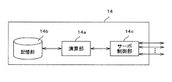
- FIG. 2 is a functional block diagram schematically showing the configuration of the control device for the robot shown in FIG.
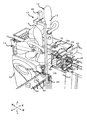
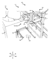
- FIG. 3 is a perspective view schematically showing a state where food is supplied to the gripping part by the supply part.
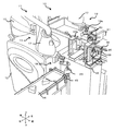
- FIG. 4 is a perspective view schematically showing a state where the food is gripped by the gripping portion.
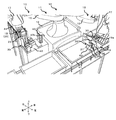
- FIG. 5 is a perspective view schematically showing a state in which the food is being transported onto the tray by the transport unit.
- FIG. 6 is a perspective view schematically showing a part of a robot to which the food stuffing apparatus according to the second embodiment is applied.
- FIG. 7 is a perspective view schematically showing a part of a robot to which the food stuffing apparatus according to the third embodiment is applied.
- the food 40 stuffing device 10 is a device that stuffs a plurality of foods 40 into a tray 41.
- the case where the foodstuff 40 stuffing device 10 according to the present invention is configured by the robot 11 shown in FIG. 1 will be described.
- the stuffing device 10 for the food 40 is not limited to the case where it is configured by the robot 11.
- the food 40 is a food product having a certain shape, and examples thereof include a rice ball and a sandwich.
- the robot 11 is housed in a carriage 12, a pair of robot arms (hereinafter sometimes simply referred to as “arms”) 13 and 13 supported by the carriage 12, and the carriage 12. And a control device 14.
- Each arm 13 is a horizontal articulated robot arm, and includes an arm unit 15, a wrist unit 17, and hand units 18 and 19.
- the arm unit 15 and the wrist unit 17 function as a transport unit that transports the plurality of foods 40 onto the tray 41.
- the left arm 13 and the right arm 13 may have substantially the same structure except for the hand portions 18 and 19. Further, the left arm 13 and the right arm 13 can operate independently or operate in association with each other.
- the arm portion 15 is composed of a first link 15a and a second link 15b.
- the first link 15 a is connected to a base shaft 16 fixed to the upper surface of the carriage 12 by a rotary joint J ⁇ b> 1 and is rotatable around a rotation axis L ⁇ b> 1 passing through the axis of the base shaft 16.
- the second link 15b is connected to the distal end of the first link 15a by the rotary joint J2, and is rotatable around the rotation axis L2 defined at the distal end of the first link 15a.
- the list unit 17 includes an elevating unit 17a and a rotating unit 17b.
- the raising / lowering part 17a is connected with the front-end
- the rotating part 17b is connected to the lower end of the elevating part 17a by the rotary joint J4, and can be rotated around the rotation axis L3 defined at the lower end of the elevating part 17a.
- the right hand unit 18 and the left hand unit 19 are connected to the rotating unit 17b of the wrist unit 17.
- the right hand unit 18 is configured by a supply unit 20 that supplies food 40
- the left hand unit 19 is configured by a gripping unit 30 that grips the food 40.
- the supply unit 20 is provided at the tip of the right arm (first arm) 13, and the gripping unit 30 is provided at the tip of the left arm (second arm) 13.
- the supply unit 20 has an adsorption head 23 that adsorbs the food 40
- the grip unit 30 has an adsorption port 31 that adsorbs the food 40. Details of the right hand unit 18 and the left hand unit 19 will be described later.
- the suction head 23 is connected to the vacuum generator 25 via the first pipe 24, and the suction port 31 is connected to the vacuum generator 25 via the second pipe 32.
- the vacuum generator 25 is a device that generates a negative pressure in the suction head 23 and the suction port 31 such as a vacuum pump or CONVUM (registered trademark), and is provided in the carriage 12 or the arm 13.
- Each of the first pipe 24 and the second pipe 32 is provided with, for example, an on-off valve (not shown). By opening and closing each of the first pipe 24 and the second pipe 32 by the on-off valve, the suction by the suction head 23 and the suction port 31 and the release thereof are performed.
- the operation of the vacuum generator 25 and the opening / closing of the on-off valve are controlled by the control device 14.
- the vacuum generator 25 can suck the food 40 by sucking it through the suction head 23 and the suction port 31.
- one vacuum generator 25 is connected to both the suction head 23 and the suction port 31, but the vacuum generator 25 connected to the suction head 23 and the vacuum generator connected to the suction port 31. And may be provided separately.
- Each arm 13 having the above configuration has each joint J1 to J4.
- the arm 13 is provided with a drive servomotor (not shown) and an encoder (not shown) for detecting the rotation angle of the servomotor so as to be associated with each joint J1 to J4. It has been.
- the rotation axes L1 of the first links 15a and 15a of the two arms 13 and 13 are on the same straight line, and the first link 15a of one arm 13 and the first link 15a of the other arm 13 are up and down. It is arranged with a height difference.
- the control device 14 includes a calculation unit 14a such as a CPU, a storage unit 14b such as a ROM and a RAM, and a servo control unit 14c.
- the control device 14 is a robot controller including a computer such as a microcontroller.
- the control device 14 may be configured by a single control device 14 that performs centralized control, or may be configured by a plurality of control devices 14 that perform distributed control in cooperation with each other.
- the storage unit 14b stores information such as a basic program as a robot controller and various fixed data.
- the calculation unit 14a controls various operations of the robot 11 by reading and executing software such as a basic program stored in the storage unit 14b. That is, the arithmetic unit 14a generates a control command for the robot 11 and outputs it to the servo control unit 14c.
- the servo control unit 14c is configured to control the driving of the servo motors corresponding to the joints J1 to J4 of each arm 13 of the robot 11 based on the control command generated by the calculation unit 14a.
- the right hand unit 18 and the left hand unit 19 will be described with reference to FIGS. 3 to 5, the first pipe 24 and the second pipe 32 are omitted for easy understanding.
- the right hand unit 18 is configured by the supply unit 20 and the left hand unit 19 is configured by the gripping unit 30, but the right hand unit 18 is configured by the gripping unit 30 and the left hand unit 19 is supplied.
- the unit 20 may be configured.
- the left hand unit 19 includes a mounting unit 19 a that mounts the grip unit 30 on the wrist unit 17 in addition to the grip unit 30.
- the mounting part 19a can mount
- the mounting portion 19a is constituted by a pair of plate-like members, for example, and the interval between them can be adjusted. Accordingly, the mounting portion 19a can be mounted by replacing the plurality of gripping portions 30 by holding the mounted portion between the pair of plate-like members.
- the right hand unit 18 may also be provided with a mounting unit that mounts the supply unit 20 on the wrist unit 17. Further, the mounting part 19 a of the left hand part 19 and the mounting part of the right hand part 18 may be attachable to the supply part 20 and the grip part 30. Thereby, the left hand part 19 and the right hand part 18 can mount
- the supply unit 20 includes one or a plurality of (one in this embodiment) suction heads 23 and supplies the food 40 to the grip unit 30.
- the tip of the suction head 23 is a suction pad made of an elastic material such as rubber, and has a cap shape that opens downward.
- the suction head 23 is connected to the rotating portion 17b of the wrist portion 17 so that the opening faces downward, and rotates around the axis extending in the vertical direction by the rotation of the rotating portion 17b.
- the gripping unit 30 grips the plurality of foods 40 arranged by the supply unit 20 and moves between the work table 42 and the tray 41.
- the grip portion 30 is disposed on the work table 42, the grip portion 30 is held by a holder 43 fixed on the work table 42.
- the holder 43 includes, for example, a lower part, a side part, and an upper part.
- the lower part of the holder 43 is fixed, and the side part supports the upper part with respect to the lower part.
- the upper part has a flat plate shape and extends in parallel with the upper surface of the work table 42, and is formed with a notch 43a.
- the notch 43a is provided on the side where the tray 41 is disposed in the upper part.
- the grip 30 includes a handle member 33, a pedestal member 34, a rotating member 35, a mounting member 36, a pair of support members 37, and an adjustment member 38.
- the handle member 33 is a mounted portion that is mounted by the mounting portion 19 a and has, for example, a cylindrical shape and is provided on the upper surface of the pedestal member 34. When the grip portion 30 is disposed on the work table 42, the handle member 33 is fitted into the notch 43 a of the holder 43.
- the base member 34 is a base for the rotating member 35 and has, for example, an L shape having an upper portion and a side portion.
- a handle member 33 is attached to the upper portion of the base member 34.
- the side portion has a plate shape extending downward from the upper portion.
- the rotating member 35 is a portion that rotates with respect to the pedestal member 34 to change the direction of the food 40 and is rotatably attached to a side portion of the pedestal member 34.
- the rotating member 35 is connected to an actuator or the like, whereby the rotating member 35 rotates.
- the operation of the rotating member 35 is controlled by the control device 14.
- the mounting member 36 is a portion that supports the food 40 from below when the food 40 supported by the support member 37 is carried.
- the mounting member 36 is, for example, L-shaped and has a side portion and a lower portion.
- the side part is connected to the rotating member 35, and the direction of the lower part is changed as the rotating member 35 rotates.
- the lower part has a plate shape and is provided horizontally when the food 40 is placed and transported.
- the support member 37 extends over both sides of the plurality of foods 40 in the direction in which the plurality of foods 40 are arranged. That is, the support member 37 has a dimension that covers a range between the food 40 at one end and the food 40 at the other end of the plurality of foods 40 arranged side by side.
- the support member 37 has, for example, a rectangular flat plate shape, and has two flat main surfaces opposed to each other, and one of the main surfaces is a contact surface that contacts the food 40 supported by the support member 37.
- the pair of support members 37 are connected to the rotation member 35 via the adjustment member 38.
- the pair of support members 37 are arranged in a C shape so that the distance between them becomes narrower toward the connection portion.
- the adjustment member 38 is connected to an actuator (not shown) or the like, and is connected to one or both of the pair of support members 37 such that the adjustment member 38 moves linearly and the distance between the pair of support members 37 changes. Has been. By this adjustment member 38, the pair of support members 37 grips the plurality of foods 40 with the interval between them being reduced.
- a plurality of suction ports 31 are provided on the contact surface of the support member 37 that contacts the food 40.
- the plurality of suction ports 31 are arranged in a plurality of rows (here, two rows) in a direction orthogonal to the direction in which the plurality of foods 40 are arranged. Further, the plurality of suction ports 31 are arranged in a plurality of rows (eight rows here) in the direction in which the plurality of foods 40 are arranged. Thereby, a plurality of suction ports 31 are assigned to one food 40.
- the outer surface of the food 40 has three rectangular planes and two triangular planes. The two triangular planes are provided in parallel to each other.
- a work table 42 and a belt conveyor 44 are disposed in front of the robot 11, and a tray 41 is disposed on the side of the robot 11 (on the left side in this embodiment).
- the work table 42 is a table for temporarily placing the food 40 and is disposed on the right side of the belt conveyor 44.
- the belt conveyor 44 is a device for transferring the food 40 to the front of the robot 11 and extends in the left-right direction.
- the triangular plane of the food 40 has a larger area than the quadrangular plane, the food 40 is conveyed in the left-right direction by the belt conveyor 44 with the triangular plane directed in the vertical direction.
- the grip portion 30 on the work table 42 is arranged so that the connection portion of the pair of support members 37 is on the tray 41 side and the opening portion is on the belt conveyor 44 side.
- the opening portion of the support member 37 is a portion facing the connection portion of the support member 37 and having the widest distance between each other.
- the tray 41 is a container for holding the food 40 for shipping, for example, and opens upward.
- a sensor 45 is disposed on the side of the belt conveyor 44 in the vicinity of the work table 42.
- the sensor 45 detects the food 40 conveyed to the belt conveyor 44 and outputs a detection signal to the control device 14.
- the vicinity of the camera 46 and the work table 42 is disposed on the belt conveyor 44.
- the camera 46 images the food 40 conveyed to the belt conveyor 44 and outputs the captured image to the control device 14.
- the control device 14 analyzes the image and determines the direction of the food 40.
- the sensor 45 detects the food 40.
- the control device 14 receives a detection signal from the sensor 45, acquires an image of the food 40 with the camera 46, and sucks the triangular plane of the food 40 with the suction head 23 of the right hand portions 18 and 19.
- the control apparatus 14 determines the direction of the food 40 based on the image from the camera 46, and adjusts the direction of the food 40 by the list part 17 based on the determination result.
- the direction of the food 40 is adjusted based on the grip portion 30. For example, the direction of the food 40 is changed so that the apex of the food 40 is on the connection part side of the pair of support members 37 and the rectangular plane facing the apex is on the opening part side of the pair of support members 37.
- the food 40 is conveyed from the belt conveyor 44 to the gripping unit 30 by the wrist unit 17 and the arm unit 15, and the food 40 is placed on the mounting member 36 of the gripping unit 30.
- the food 40 is placed on the mounting member 36 between the pair of support members 37 so that the two rectangular planes of the food 40 are respectively along the contact surfaces of the pair of support members 37.
- a series of operations from adsorption to placement of the food 40 is repeated, and a plurality of foods 40 are placed on the placement member 36.
- the food 40 is supplied to the grip portion 30, and the plurality of foods 40 are arranged so that the triangular planes of the food 40 are in contact with each other between the pair of support members 37.
- the interval between the pair of support members 37 is narrowed by the adjustment member 38, and a plurality of foods 40 are sandwiched between the pair of support members 37.
- the support member 37 extends over both sides of the plurality of foods 40 in the direction in which the plurality of foods 40 are arranged, all the foods 40 are sandwiched between the pair of support members 37.
- the food 40 is adsorbed from the suction port 31 and the food 40 in contact with the contact surface is stuck to the contact surface.
- since the plurality of suction ports 31 are arranged so as to be assigned to each food 40, all the food 40 is adsorbed by the suction ports 31. Thereby, the some food 40 is hold
- the grip part 30 is moved to the rear side by the arm part 15. As a result, the handle member 33 is detached from the notch 43 a and the grip portion 30 is separated from the holder 43.
- the gripping unit 30 is transported from the work table 42 onto the tray 41 by the arm unit 15 and the wrist unit 17. At this time, the posture of the grip portion 30 is maintained so that the placement member 36 is horizontal. As a result, the plurality of foods 40 are supported by the mounting member 36 together with the pair of support members 37, thereby being more reliably transported.
- the rotating member 35 is rotated on the tray 41.
- the support member 37 whose longitudinal direction extends in the up-down direction rotates and changes its direction in the horizontal direction (the left-right direction in this embodiment).
- the rectangular plane of the food 40 located on the opening side of the pair of support members 37 faces downward. Then, the grip portion 30 is lowered by the wrist portion 17 and the food 40 is put in the tray 41.
- the suction from the suction port 31 is released and the pair of support members 37 are expanded by the adjustment member 38. Thereby, the food 40 is separated from the grip portion 30 and the food 40 is accommodated in the tray 41. Then, the support member 37 is rotated by the rotating member 35 so as to be directed in the vertical direction, and the grip portion 30 is returned from the tray 41 to the holder 43 on the work table 42 by the wrist portion 17 and the arm portion 15.
- each gripping unit 30 is installed in each holder 43. Then, while a predetermined number of foods 40 are supplied to one gripping part 30 and one gripping part 30 is being transported from the work table 42 to the tray 41, the food 40 is then supplied to the other gripping part 30. The Then, after the food 40 is stored in the tray 41 by the one gripping portion 30, when the one gripping portion 30 is returned to the holder 43 on the work table 42, the one gripping portion 30 is separated from the mounting portion 19a. The other mounting portion 19a is mounted. As a result, a series of operations from the supply of the food 40 to the gripping portion 30 to the accommodation in the tray 41 are alternately performed by the two gripping portions 30, and therefore the work process time can be shortened.
- the gripping unit 30 grips the plurality of foods 40 across both sides of the plurality of foods 40 in the direction in which the plurality of foods 40 are arranged by the supply unit 20.
- the pair of support members 37 grips the plurality of foods 40 with the interval between them reduced.
- the support member 37 adsorbs the food 40 on the contact surface via the suction port 31 and holds the food 40 in a sandwiched manner. For this reason, even if the food 40 is easily deformed, such as rice balls and sandwiches, the food 40 can be accommodated in the tray 41 without being deformed by gripping and transporting the food 40 by the support member 37. Therefore, an increase in non-conforming products can be prevented, and a reduction in work efficiency can be suppressed.
- the mounting unit 19a mounts a plurality of gripping units 30 in a replaceable manner. Thereby, the some holding
- the grip portion 30 further includes a placement member 36 that extends in a direction orthogonal to the direction in which the plurality of foods 40 are arranged and on which the foods 40 are placed. Thereby, the some foodstuff 40 can be hold
- the supply unit 20 has an adsorption head 23 that adsorbs the food 40.
- the suction head 23 sucks the food 40 and supplies it to the gripping unit 30. For this reason, even if it is the food 40 which is easy to deform
- the outer surface of the food 40 has a pair of parallel triangular planes, and a plurality of foods 40 are arranged so that the triangular planes are in contact with each other and lifted by the pair of support members 37.
- grip the food 40 while being able to hold
- the grip portion 30 includes the adjustment member 38, but the grip portion 30 may not include the adjustment member 38.
- the distance between the pair of support members 37 is kept constant, and the food 40 is not sandwiched between the pair of support members 37.
- the plurality of suction ports 31 are provided on the contact surface of the support member 37, the food 40 is gripped by the suction of the suction ports 31.
- the suction port 31 is provided in the support member 37, the suction port 31 may not be provided in the support member 37.
- the food 40 is not adsorbed by the adsorption port 31.
- the pair of support members 37 are gripped by sandwiching the food 40 with the distance between them being reduced by the adjustment member 38.
- the grip part 30 may not have the mounting member 36.
- the grip part 30 may not have the mounting member 36.
- a pair of support members 37 may be disposed on the work table 42, and the food 40 may be placed on the work table 42 between the pair of support members 37. .
- the robot 11 includes the first arm 13 having the supply unit 20 at the tip and the second arm 13 having the grip 30 at the tip.
- the supply unit 20 may be detachably mounted on the wrist unit 17 via a mounting unit (not shown).
- the supply unit 20 is mounted on the wrist unit 17 by the mounting unit and provided at the tip of the arm 13. According to this, for example, by using the general-purpose robot 11 whose tip can be replaced, food can be stuffed only by replacing the tip.
- the stuffing device 10 for food 40 according to the first embodiment includes a plurality of gripping units 30.
- the number of gripping portions 30 is not limited to this, and may be one.
- the stuffing device 10 for food 40 according to the second embodiment includes one gripping unit 30.
- the gripping unit 30 grips the plurality of foods 40 arranged by the supply unit 20 and moves between the vicinity of the belt conveyor 44 and the tray 41.
- the grip portion 30 is attached to the wrist portion 17 by the attachment portion 19a. In this case, since it is not necessary to replace the grip part 30, the left hand part 19 may not be provided with the mounting part 19a.
- the grip 30 may be lowered by the amount of the food 40 placed each time the food 40 is placed on the placement member 36.
- the height of the food 40 adsorbed by the adsorption head 23 and the place where the food 40 is placed on the grip portion 30 (the upper surface of the placement member 36 or the food 40 placed on the placement member 36).
- the height of the upper surface can be made to coincide with each other. Therefore, after the food 40 on the belt conveyor 44 is adsorbed by the adsorbing head 23, the adsorbing head 23 is raised to a predetermined height, and the adsorbing head 23 is moved to the gripping portion 30 at that height to cancel the adsorption. To do. As a result, the food 40 is supplied to the grip portion 30.
- the food device 40 stuffing device 10 can be made compact and simplified.
- the grip portion 30 may not have the adjustment member 38.
- the suction port 31 may not be provided in the support member 37.
- the grip portion 30 may not have the placement member 36. In this case, the work table 42 may be used when the food 40 is supplied to the grip portion 30.
- the supply unit 20 has one suction head 23.
- the number of suction heads 23 is not limited to this, and may be plural.
- the supply unit 20 of the stuffing device 10 for food 40 according to the third embodiment includes a plurality of suction heads 23 and a rotating body 26.
- the rotating body 26 rotates around an axis parallel to the direction in which the plurality of suction heads 23 are connected and the plurality of foods 40 are arranged.
- the rotating body 26 includes a shaft portion 26a and four straight portions 26b.
- the shaft portion 26a is connected to the wrist portion 17 and extends in the vertical direction.
- the shaft portion 26a has, for example, a cylindrical shape and can be rotated in the circumferential direction.
- the four straight portions 26b centering on the shaft portion 26a extend in a direction orthogonal to the shaft portion 26a while being spaced radially.
- a suction head 23 is provided at the end of the straight portion 26b via an elastic member 26c.
- the suction head 23 extends downward in a direction parallel to the shaft portion 26a.
- Each suction head 23 is connected to a vacuum generator 25 (FIG. 1) via a first pipe 24 (FIG. 1).
- the elastic member 26c extends in a direction parallel to the shaft portion 26a and expands / contracts its length.
- the expansion / contraction member 26 c on the belt conveyor 44 extends and the suction head 23 descends to adsorb the food 40 on the belt conveyor 44 and then expand and contract.
- the member 26c contracts and the suction head 23 rises.
- the rotating body 26 rotates around the shaft portion 26 a, and another suction head 23 moves onto the belt conveyor 44.
- a series of operations of extending the expansion member 26c, adsorption of the suction head 23, contraction of the expansion member 26c, and rotation of the rotating body 26 is performed.
- the adsorption head 23 is moved to the grip portion 30.
- the suction of the suction head 23 is released, and the food 40 is placed on the placement member 36 of the grip portion 30. Subsequently, the rotating body 26 rotates around the shaft portion 26 a to release the suction of another suction head 23. A series of operations of releasing the adsorption and rotating the rotating body 26 is repeated to supply all the foods 40 to the grip unit 30.
- the grip 30 may be lowered by the amount of the food 40 placed each time the food 40 is placed on the placement member 36.
- the height of the food 40 adsorbed by the adsorption head 23 and the place where the food 40 is placed in the grip portion 30 (the upper surface of the placement member 36 or the food 40 placed on the placement member 36).
- the height of the upper surface can be made to coincide with each other.
- the supply unit 20 further includes the rotating body 26 that is connected to the plurality of adsorption heads 23 and rotates about an axis parallel to the direction in which the plurality of foods 40 are arranged.
- the food 40 stuffing apparatus 10 may further include a plurality of suction heads 23 and a rotating body 26. Thereby, the improvement of the further work efficiency is achieved.
- the grip portion 30 may not have the adjustment member 38.
- the suction port 31 may not be provided in the support member 37.
- the grip portion 30 may not have the placement member 36. In this case, the work table 42 may be used when the food 40 is supplied to the grip portion 30.
- the suction head 23 is used for the supply part 20, if the foodstuff 40 can be supplied to the work table 42 etc., it will not be limited to this.
- the supply unit 20 may be an L-shaped plate member.
- the food 40 may be scooped up by an L-shaped plate member and supplied to the grip portion 30.
- the present invention is useful as a food stuffing device or the like that can suppress a decrease in work efficiency.
Landscapes
- Engineering & Computer Science (AREA)
- Mechanical Engineering (AREA)
- Robotics (AREA)
- Life Sciences & Earth Sciences (AREA)
- Food Science & Technology (AREA)
- Manipulator (AREA)
- Specific Conveyance Elements (AREA)
- Container Filling Or Packaging Operations (AREA)
Abstract
食品(40)の詰め込み装置(10)は、食品を供給する供給部(20)と、前記供給部により複数の前記食品が並べられる方向において複数の前記食品の両側に亘って複数の前記食品を把持する把持部と、前記把持部により把持された複数の前記食品をトレイ上に搬送する搬送部と、を備えている。
Description
本発明は、食品をトレイに詰め込む食品の詰め込み装置に関する。
従来、食品をトレイに詰め込む装置として、たとえば、特許文献1に示す食品のコンテナ詰め装置が知られている。この食品のコンテナ詰め装置では、食品は搬送コンベアから固定シュート板に落下する。この固定シュート板においてタイミングホルダおよび保持容器により食品は順次向きを変えながら落下していく。そして、所定の姿勢になった食品が固定シュート板から搬送部に落下し、搬送部により搬送されるコンテナに重ね入れられていく。
特許文献1の食品のコンテナ詰め装置では、食品をタイミングホルダ、保持容器およびコンテナに順次落下させている。この食品のコンテナ詰め装置で、おにぎりおよびサンドイッチなどの食品をコンテナに詰め込むことが考えられる。このような食品は、変形し易く、外力により一度変形すると、外力を除いても元の形には戻らない。よって、食品が落下した際に食品が外力を受けて変形すると、食品の変形により商品価値が損なわれる。この結果、不適合品の割合が増え、作業効率が低下してしまうおそれがある。
本発明は上記のような課題を解決するためになされたもので、作業効率の低下を抑制することができる食品の詰め込み装置を提供することを目的としている。
上記目的を達成するために、本発明のある形態に係る食品の詰め込み装置は、食品を供給する供給部と、前記供給部により複数の前記食品が並べられる方向において複数の前記食品の両側に亘って複数の前記食品を把持する把持部と、前記把持部により把持された複数の前記食品をトレイ上に搬送する搬送部と、を備えている。
これによれば、変形し易い食品であっても、把持部材により食品を把持することにより、変形することなく食品をトレイに収容することができる。よって、不適合品の増加を防ぎ、作業効率が低下を抑制することができる。
この食品の詰め込み装置では、前記把持部は、一対の支持部材と、一対の前記支持部材の互いの間隔を調整可能である調整部材と、を有し、一対の前記支持部材は、互いの間隔を縮めて複数の前記食品を挟んで把持してもよい。これによれば、変形し易い食品であっても、一対の支持部材により食品を挟持することにより、変形することなく食品をトレイに収容することができる。
この食品の詰め込み装置では、前記把持部は、支持部材と、前記支持部材において前記食品と当接する当接面に設けられた吸着口と、を有し、前記支持部材は、前記吸着口を介して前記当接面に前記食品を吸着させて複数の前記食品を挟んで把持してもよい。これによれば、変形し易い食品であっても、吸着口により食品を吸着することにより、変形することなく食品をトレイに収容することができる。
この食品の詰め込み装置では、複数の前記把持部を交換可能に装着する装着部をさらに備えていてもよい。これによれば、装着した1つの把持部により食品を搬送している間に、装着していない他の把持部に食品を供給することにより、作業効率の向上を図ることができる。
この食品の詰め込み装置では、前記把持部は、複数の前記食品が並べられる方向に対して直交する方向に延び、かつ、前記食品が載置される載置部材をさらに有していてもよい。これによれば、支持部材に加えて載置部材により食品を支えることにより、より確実に食品を把持することができる。
この食品の詰め込み装置では、前記供給部は、前記食品を吸着する1つまたは複数の吸着ヘッドを有していてもよい。これによれば、変形し易い食品であっても、吸着ヘッドにより食品を吸着することにより、変形することなく食品を把持部に供給することができる。
この食品の詰め込み装置では、前記供給部は、複数の前記吸着ヘッドが接続され、かつ、複数の前記食品が並べられる方向に平行な軸を中心に回転する回転体をさらに有していてもよい。これによれば、たとえば、ベルトコンベアと把持部との往復移動の回数を減らせるため、作業効率の向上が図られる。
この食品の詰め込み装置は、前記食品の外表面は平行な一対の平面を有しており、その平面どうしが接するように並べられた複数の前記食品を前記把持部により把持してもよい。これにより、トレイにおける食品の収納率を向上させ、作業効率の向上が図られる。
この食品の詰め込み装置は、前記供給部を先端に有する第1アームと、前記把持部を先端に有する第2アームと、を備えたロボットにより構成されていてもよい。これによれば、たとえば、先端を取替可能な汎用ロボットを使用することにより、先端を取り替えるだけで、食品の詰め込み作業が可能となる。
本発明は、以上に説明した構成を有し、作業効率の低下を抑制することができるという効果を奏する。
以下、好ましい実施形態を、図面を参照しながら説明する。なお、以下では全ての図面を通じて同一または相当する要素には同一の参照符号を付して、その重複する説明を省略する。また、図面は理解しやすくするために、それぞれの構成要素を模式的に示したものである。さらに、一対のアームを広げた方向を左右方向と称し、基軸の軸心に平行な方向を上下方向と称し、左右方向および上下方向に直交する方向を前後方向と称する。
(実施形態1)
本実施形態1に係る食品40の詰め込み装置10は、複数の食品40をトレイ41に詰め込む装置である。図1に示すロボット11により本発明に係る食品40の詰め込み装置10を構成した場合について説明する。ただし、食品40の詰め込み装置10はロボット11により構成される場合に限定されない。なお、このロボット11について、水平多関節型の双腕ロボットを説明するが、水平多関節型・垂直多関節型などのロボットを採用することができる。また、食品40は、一定の形状を有する食料品であって、たとえば、おにぎりおよびサンドイッチが例示される。
本実施形態1に係る食品40の詰め込み装置10は、複数の食品40をトレイ41に詰め込む装置である。図1に示すロボット11により本発明に係る食品40の詰め込み装置10を構成した場合について説明する。ただし、食品40の詰め込み装置10はロボット11により構成される場合に限定されない。なお、このロボット11について、水平多関節型の双腕ロボットを説明するが、水平多関節型・垂直多関節型などのロボットを採用することができる。また、食品40は、一定の形状を有する食料品であって、たとえば、おにぎりおよびサンドイッチが例示される。
ロボット11は、図1に示すように、台車12と、台車12に支持された一対のロボットアーム(以下、単に「アーム」と記載する場合がある)13、13と、台車12内に収納された制御装置14とを備えている。各アーム13は、水平多関節型ロボットアームであって、アーム部15とリスト部17とハンド部18、19とを備えている。アーム部15およびリスト部17は、複数の食品40をトレイ41上に搬送する搬送部として機能する。なお、左のアーム13および右のアーム13は、ハンド部18、19を除いて実質的に同じ構造であってもよい。また、左のアーム13および右のアーム13は、独立して動作したり、互いに関連して動作したりすることができる。
アーム部15は、本例では、第1リンク15aおよび第2リンク15bとで構成されている。第1リンク15aは、台車12の上面に固定された基軸16と回転関節J1により連結され、基軸16の軸心を通る回転軸線L1まわりに回動可能である。第2リンク15bは、第1リンク15aの先端と回転関節J2により連結され、第1リンク15aの先端に規定された回転軸線L2まわりに回動可能である。
リスト部17は、昇降部17aおよび回動部17bにより構成されている。昇降部17aは、第2リンク15bの先端と直動関節J3により連結され、第2リンク15bに対し昇降移動可能である。回動部17bは、昇降部17aの下端と回転関節J4により連結され、昇降部17aの下端に規定された回転軸線L3まわりに回動可能である。
右ハンド部18および左ハンド部19は、リスト部17の回動部17bに連結されている。右ハンド部18は、食品40を供給する供給部20により構成されており、左ハンド部19は、食品40を把持する把持部30により構成されている。供給部20は右のアーム(第1アーム)13の先端に設けられ、把持部30は左のアーム(第2アーム)13の先端に設けられている。供給部20は食品40を吸着する吸着ヘッド23を有し、把持部30は食品40を吸着する吸着口31を有している。なお、右ハンド部18および左ハンド部19の詳細については後述する。
吸着ヘッド23は第1配管24を介して真空発生装置25に接続されており、吸着口31は第2配管32を介して真空発生装置25に接続されている。真空発生装置25は、たとえば、真空ポンプやCONVUM(登録商標)など、吸着ヘッド23および吸着口31に負圧を発生させる装置であり、台車12やアーム13に設けられている。第1配管24および第2配管32のそれぞれには、たとえば、開閉弁(図示せず)が設けられている。開閉弁により第1配管24および第2配管32のそれぞれを開放および閉塞することによって、吸着ヘッド23および吸着口31のそれぞれによる吸着およびその解除が行われる。この真空発生装置25の動作および開閉弁の開閉は制御装置14により制御される。これにより、真空発生装置25は、吸着ヘッド23および吸着口31を介して吸引し、食品40を吸着することができる。なお、ここでは、吸着ヘッド23および吸着口31の両方に1つの真空発生装置25が接続されているが、吸着ヘッド23に接続される真空発生装置25と吸着口31に接続される真空発生装置とは別々に設けられてもよい。
上記構成の各アーム13は、各関節J1~J4を有する。そして、アーム13には、各関節J1~J4に対応付けられるように、駆動用のサーボモータ(図示せず)、および、そのサーボモータの回転角を検出するエンコーダ(図示せず)等が設けられている。また、2本のアーム13、13の第1リンク15a、15aの回転軸線L1は同一直線上にあり、一方のアーム13の第1リンク15aと他方のアーム13の第1リンク15aとは上下に高低差を設けて配置されている。
制御装置14は、図2に示すように、CPU等の演算部14aと、ROM、RAM等の記憶部14bと、サーボ制御部14cと、を備える。制御装置14は、例えばマイクロコントローラ等のコンピュータを備えたロボットコントローラである。なお、制御装置14は、集中制御する単独の制御装置14によって構成されていてもよいし、互いに協働して分散制御する複数の制御装置14によって構成されていてもよい。
記憶部14bには、ロボットコントローラとしての基本プログラム、各種固定データ等の情報が記憶されている。演算部14aは、記憶部14bに記憶された基本プログラム等のソフトウェアを読み出して実行することにより、ロボット11の各種動作を制御する。すなわち、演算部14aは、ロボット11の制御指令を生成し、これをサーボ制御部14cに出力する。サーボ制御部14cは、演算部14aにより生成された制御指令に基づいて、ロボット11の各アーム13の関節J1~J4に対応するサーボモータの駆動を制御するように構成されている。
次に、右ハンド部18および左ハンド部19について、図3~図5を参照して説明する。なお、図3~図5では、わかり易いように、第1配管24および第2配管32を省略している。また、ここでは、右ハンド部18は供給部20により構成され、左ハンド部19は把持部30により構成されているが、右ハンド部18は把持部30により構成され、左ハンド部19は供給部20により構成されていてもよい。
左ハンド部19は、把持部30に加えて、把持部30をリスト部17に装着する装着部19aにより構成されている。装着部19aは、複数の把持部30を交換可能に装着することができる。装着部19aは、たとえば、一対の板状部材により構成されており、その間隔は調整可能である。これにより、一対の板状部材で被装着部分を挟持することにより、装着部19aは複数の把持部30を取り換えて装着することができる。なお、右ハンド部18にも供給部20をリスト部17に装着する装着部が設けられていてもよい。また、左ハンド部19の装着部19aおよび右ハンド部18の装着部は、供給部20および把持部30に装着可能であってもよい。これにより、左ハンド部19および右ハンド部18は、供給部20および把持部30を交換可能に装着することができる。
供給部20は、1つまたは複数(この実施形態では、1つ)の吸着ヘッド23を有し、食品40を把持部30へ供給する。吸着ヘッド23の先端部は、ゴムなどの弾性材料で形成された吸着パッドであり、下方向に開口するキャップ形状を有している。吸着ヘッド23は、その開口が下方を向くようにリスト部17の回動部17bに接続されており、上下方向に延びる軸を中心に回動部17bの回動により回る。
把持部30は、供給部20により並べられた複数の食品40を把持して、作業台42とトレイ41との間を移動する。把持部30が作業台42上に配置されている際、把持部30は作業台42上に固定されたホルダ43に保持されている。
ホルダ43は、たとえば、下部、側部および上部を備えている。ホルダ43の下部は固定されており、側部は下部に対して上部を支持する。上部は、平板形状であって、作業台42の上面に対して平行に延び、切欠き43aが形成されている。切欠き43aは、上部においてトレイ41が配置されている側に設けられている。
把持部30は、把手部材33、台座部材34、回転部材35、載置部材36、一対の支持部材37および調整部材38を有している。把手部材33は、装着部19aにより装着される被装着部分であって、たとえば、円柱形状を有しており、台座部材34の上面に設けられている。把持部30が作業台42に配置されている際、把手部材33はホルダ43の切欠き43aに嵌められる。
台座部材34は、回転部材35に対する土台であり、たとえば、上部および側部を有するL字状である。台座部材34の上部には、把手部材33が取り付けられている。側部は、上部から下方に延びた板状形状である。
回転部材35は、台座部材34に対して回転して食品40の向きを変える部分であり、台座部材34の側部に回転自在に装着されている。回転部材35は、アクチュエータなどに接続されており、これにより回転部材35は回転する。回転部材35の動作は制御装置14により制御されている。
載置部材36は、支持部材37により支持された食品40が運ばれる際に下方から食品40を支持する部分である。載置部材36は、たとえば、L字状であって、側部および下部を有している。側部は回転部材35に接続されており、回転部材35に回転に伴い下部の向きを変える。下部は、板形状であって、食品40が載置および搬送される際に水平に設けられる。
支持部材37は、複数の食品40が並べられる方向において複数の食品40の両側に亘って延びる。つまり、支持部材37は、並べられた複数の食品40の一方端にある食品40と他方端にある食品40との間の範囲に及ぶ寸法である。支持部材37は、たとえば、矩形の平板形状であって、対向する2つの平らな主面を有し、その一方主面は支持部材37により支持された食品40に当接する当接面である。
一対の支持部材37は、調整部材38を介して回転部材35に接続されている。たとえば、一対の支持部材37は、その互いの間隔が接続部分に向かって狭くなってなるように、ハ字形状に配置されている。調整部材38は、アクチュエータ(図示せず)などに接続されており、直線的に移動し、一対の支持部材37の互いの間隔が変化するように、一対の支持部材37の一方または両方に接続されている。この調整部材38により、一対の支持部材37は互いの間隔を縮めて複数の食品40を挟んで把持する。
支持部材37において食品40に当接する当接面に複数の吸着口31が設けられている。複数の吸着口31は、複数の食品40が並ぶ方向に直交する方向において、複数の列(ここでは、2列)、並んでいる。また、複数の吸着口31は、複数の食品40が並ぶ方向において、複数の列(ここでは、8列)、並んでいる。これにより、1つの食品40に対して複数の吸着口31が割り当てられる。
次に、上記構成のロボット11による食品40をトレイ41に詰め込む方法について図3~図5を参照して説明する。この方法は制御装置14により制御されている。なお、ここでは、食品40としてフィルムで包装された三角形状のおにぎりを用い、この詰め込み方法について説明する。なお、他の食品40でも詰め込み方法が同じであるため、その説明は省略する。また、食品40の外表面は、3つの四角形状平面、および、2つの三角形状平面を有している。2つの三角形状平面は互いに平行に設けられている。
図3に示すように、ロボット11の前には、作業台42およびベルトコンベア44が配置され、ロボット11の側方(この実施形態では、左側)にはトレイ41が配置されている。作業台42は食品40を仮置きするための台であり、ベルトコンベア44の右側に配置されている。ベルトコンベア44は食品40をロボット11の前まで移送するための装置であり、左右方向に延びている。この実施形態では、食品40の三角形状平面は四角形状平面より面積が大きいため、食品40は三角形状平面を上下方向に向けてベルトコンベア44により左右方向に運ばれる。作業台42上の把持部30は、一対の支持部材37の接続部分がトレイ41側になり、開口部分がベルトコンベア44側になるように配置される。なお、支持部材37の開口部分は、支持部材37の接続部分に対向し、かつ、互いの間隔が最も広い部分である。トレイ41は、たとえば、出荷するために食品40を保持するための容器であり、上方に開口している。
また、センサ45が、作業台42の近傍においてベルトコンベア44の側方に配置されている。センサ45は、ベルトコンベア44に搬送される食品40を検知し、検知信号を制御装置14に出力する。さらに、カメラ46、作業台42の近傍においてがベルトコンベア44の上に配置されている。カメラ46は、ベルトコンベア44に搬送される食品40を撮影し、撮影した画像を制御装置14に出力する。制御装置14は、画像を解析して、食品40の向きを判定する。
まず、食品40がベルトコンベア44によりロボット11の近傍に運ばれてくると、センサ45は食品40を検知する。制御装置14は、センサ45からの検知信号を受けて、カメラ46により食品40の画像を取得すると共に、右ハンド部18、19の吸着ヘッド23により食品40の三角形状平面を吸着させる。そして、制御装置14は、カメラ46からの画像に基づき食品40の向きを判定し、判定結果に基づいて食品40の向きをリスト部17により調整する。ここで、食品40の向きは把持部30に基づいて調整される。たとえば、食品40の頂点が一対の支持部材37の接続部分側になり、頂点に対向する四角形状平面が一対の支持部材37の開口部分側になるように、食品40の向きが変えられる。
そして、食品40をリスト部17およびアーム部15によりベルトコンベア44から把持部30へ搬送し、食品40を把持部30の載置部材36に載置する。このとき、食品40の2つの四角形状平面が一対の支持部材37の当接面にそれぞれ沿うように、一対の支持部材37間において食品40を載置部材36上に置く。この食品40の吸着から載置までの一連の作業を繰り返し、複数の食品40を載置部材36上に載置していく。これにより、食品40が把持部30に供給され、一対の支持部材37間において食品40の三角形状平面どうしが接するように複数の食品40が並べられる。
図4に示すように、一連の供給作業が繰り返され、所定数(この実施形態では、4個)の食品40が並べられる。続いて、左ハンド部19の装着部19aは、把手部材33を挟むことにより、把持部30はリスト部17に装着される。
一対の支持部材37の間隔を調整部材38により狭め、複数の食品40を一対の支持部材37で挟む。この際、支持部材37は、複数の食品40が並べられる方向において複数の食品40の両側に亘って延びるため、全ての食品40が一対の支持部材37により挟みこまれる。また、吸着口31から食品40を吸着して、当接面に当接している食品40を当接面に張り付かせる。この際、複数の吸着口31が各食品40に割り当てられるように配置されているため、全ての食品40が吸着口31により吸着される。これにより、複数の食品40がより確実に把持される。
把持部30をアーム部15により後側に移動する。これにより、把手部材33は切欠き43aから外れて、把持部30はホルダ43から離れる。そして、把持部30はアーム部15およびリスト部17により作業台42からトレイ41上に搬送される。この際、載置部材36が水平になるように把持部30の姿勢が保たれる。これにより、一対の支持部材37と共に載置部材36により複数の食品40が支持されることにより、より確実に搬送される。
図5に示すように、トレイ41上において回転部材35を回転させる。これにより、長手方向が上下方向に延びていた支持部材37が回転し、水平方向(この実施形態では、左右方向)に向きを変える。一対の支持部材37の開口部側に位置している食品40の四角形状平面が下方を向く。そして、把持部30をリスト部17により下降させて、食品40をトレイ41に入れる。
吸着口31からの吸着を解除すると共に、一対の支持部材37を調整部材38により広げる。これにより、食品40が把持部30から離れ、食品40がトレイ41に収容される。そして、支持部材37を回転部材35により回転させて上下方向に向けて、把持部30をトレイ41から作業台42上のホルダ43へリスト部17およびアーム部15により戻す。
また、複数(たとえば、2つ)の把持部30が用いられる場合、作業台42に2つのホルダ43が配置され、各ホルダ43に各把持部30が設置されている。そして、一方の把持部30に所定数の食品40が供給され、一方の把持部30が作業台42からトレイ41に搬送されている間に、次に他方の把持部30に食品40が供給される。そして、一方の把持部30により食品40がトレイ41に収容された後、一方の把持部30が作業台42上のホルダ43に戻されると、一方の把持部30は装着部19aから離されて、他方の装着部19aが装着される。これにより、食品40の把持部30への供給からトレイ41への収容までの一連の作業を2つの把持部30により交互に行われるため、作業工程時間を短縮化することができる。
上記構成によれば、把持部30は、供給部20により複数の食品40が並べられる方向において複数の食品40の両側に亘って複数の食品40を把持する。たとえば、一対の前記支持部材37は、互いの間隔を縮めて複数の食品40を挟んで把持する。また、支持部材37は、吸着口31を介して当接面に食品40を吸着させて複数の食品40を挟んで把持する。このため、おにぎりおよびサンドイッチのような変形し易い食品40であっても、食品40を支持部材37により把持して搬送することにより、変形することなく食品40をトレイ41に収容することができる。よって、不適合品の増加を防ぎ、作業効率が低下を抑制することができる。
装着部19aは、複数の把持部30を交換可能に装着する。これにより、複数の把持部30を交替しながら用いることができ、作業時間の短縮化が図られる。
把持部30は、複数の食品40が並べられる方向に対して直交する方向に延び、かつ、食品40が載置される載置部材36をさらに有している。これにより、より確実に複数の食品40を把持および搬送することができる。
供給部20は、食品40を吸着する吸着ヘッド23を有している。この吸着ヘッド23により食品40を吸着して把持部30に供給する。このため、変形し易い食品40であっても、変形することなく食品40を供給することができる。
また、食品40の外表面は平行な一対の三角形状平面を有しており、その三角形状平面どうしが接するように複数の食品40が並べられて一対の支持部材37により持ち上げられる。これにより、食品40を安定的に把持することができると共に、トレイ41における食品40の収納率を向上させ、作業効率の向上が図られる。
なお、上記実施形態では、把持部30は調整部材38を有しているが、把持部30は調整部材38を有していなくてもよい。この場合、一対の支持部材37の互いの間隔は一定に保たれ、一対の支持部材37により食品40は挟持されない。ただし、支持部材37の当接面に複数の吸着口31が設けられているため、この吸着口31の吸着により食品40は把持される。
また、支持部材37に吸着口31が設けられているが、支持部材37に吸着口31が設けられていなくてもよい。この場合、吸着口31により食品40が吸着されない。ただし、一対の支持部材37はその互いの間隔が調整部材38により縮められて食品40を挟んで把持する。
さらに、把持部30は載置部材36を有しているが、把持部30は載置部材36を有していなくてもよい。この場合、食品40を把持部30に供給する際、作業台42上に一対の支持部材37を配置し、一対の支持部材37の間の作業台42上に食品40を載置してもよい。
さらに、供給部20を先端に有する第1アーム13と、把持部30を先端に有する第2アーム13と、を備えたロボット11により構成されていている。たとえば、供給部20が装着部(図示せず)を介してリスト部17に脱着可能に装着されていてもよい。供給部20が装着部によりリスト部17に装着されてアーム13の先端に設けられる。これによれば、たとえば、先端を取替可能な汎用ロボット11を使用することにより、先端を取り替えるだけで、食品の詰め込み作業が可能となる。
(実施形態2)
実施形態1に係る食品40の詰め込み装置10は、複数の把持部30を備えていた。しかしながら、把持部30の数はこれに限定されず、1つであってもよい。実施形態2に係る食品40の詰め込み装置10は、図6に示すように、1つの把持部30を備えている。
実施形態1に係る食品40の詰め込み装置10は、複数の把持部30を備えていた。しかしながら、把持部30の数はこれに限定されず、1つであってもよい。実施形態2に係る食品40の詰め込み装置10は、図6に示すように、1つの把持部30を備えている。
把持部30は、供給部20により並べられた複数の食品40を把持して、ベルトコンベア44の近傍とトレイ41との間を移動する。把持部30は装着部19aによりリスト部17に装着されている。この場合、把持部30を付け替える必要がないため、左ハンド部19に装着部19aが設けられなくてもよい。
また、把持部30は、その載置部材36に食品40が載置される度に載置された食品40の分だけ下降させていってもよい。これにより、吸着ヘッド23により吸着された食品40の高さと、把持部30において食品40が載置される場所(載置部材36の上面、または、載置部材36に載置された食品40の上面)との高さとを一致させることができる。よって、ベルトコンベア44上の食品40を吸着ヘッド23により吸着させた後、所定の高さまで吸着ヘッド23を上昇させ、その高さのまま吸着ヘッド23を把持部30へ移動させて、吸着を解除する。これにより、食品40が把持部30に供給される。
上記構成によれば、把持部30を取り換える必要がないため、装着部19a、ホルダ43および作業台42が必要なく、食品40の詰め込み装置10のコンパクト化および簡素化が図られる。
なお、実施形態2では、実施形態1と同様に、把持部30は調整部材38を有していなくてもよい。また、実施形態2では、実施形態1と同様に、支持部材37に吸着口31が設けられていなくてもよい。さらに、実施形態2では、実施形態1と同様に、把持部30は載置部材36を有していなくてもよい。この場合、食品40を把持部30に供給する際、作業台42を用いてもよい。
(実施形態3)
実施形態2に係る食品40の詰め込み装置10では、供給部20は1つの吸着ヘッド23を有していた。しかしながら、吸着ヘッド23の数はこれに限定されず、複数であってもよい。実施形態3に係る食品40の詰め込み装置10の供給部20は、図7に示すように、複数の吸着ヘッド23、および、回転体26を備えている。
実施形態2に係る食品40の詰め込み装置10では、供給部20は1つの吸着ヘッド23を有していた。しかしながら、吸着ヘッド23の数はこれに限定されず、複数であってもよい。実施形態3に係る食品40の詰め込み装置10の供給部20は、図7に示すように、複数の吸着ヘッド23、および、回転体26を備えている。
回転体26は、複数の吸着ヘッド23が接続され、かつ、複数の食品40が並べられる方向に平行な軸を中心に回転する。たとえば、回転体26は、軸部26aおよび4本の直線部26bを有している。軸部26aは、リスト部17に接続されており、上下方向に延びる。軸部26aは、たとえば、円柱形状であって、周方向に回転可能である。
軸部26aを中心に4本の直線部26bが放射線状に均等な間隔を空けながら軸部26aに対して直交する方向に延びている。直線部26bの先には吸着ヘッド23が伸縮部材26cを介して設けられている。吸着ヘッド23は、軸部26aに対し平行な方向において下方に延びる。各吸着ヘッド23は第1配管24(図1)を介して真空発生装置25(図1)に接続されている。伸縮部材26cは、軸部26aに対して平行な方向に延び、その長さを伸縮させる。
この場合、食品40をベルトコンベア44から把持部30に供給する際、ベルトコンベア44上の伸縮部材26cが延びて吸着ヘッド23が下降し、ベルトコンベア44上の食品40を吸着してから、伸縮部材26cが縮んで吸着ヘッド23が上昇する。続いて、軸部26aを中心に回転体26が回転して、別の吸着ヘッド23がベルトコンベア44上に移動する。これについても、伸縮部材26cの伸び、吸着ヘッド23の吸着、伸縮部材26cの縮み、および、回転体26の回転の一連の作業を行う。そして、全ての吸着ヘッド23により食品40を吸着すると、吸着ヘッド23を把持部30へ移動させる。
吸着ヘッド23の吸着を解除して、食品40を把持部30の載置部材36上に載置する。続いて、軸部26aを中心に回転体26が回転して、別の吸着ヘッド23の吸着を解除する。この吸着解除および回転体26の回転の一連の作業を繰り返して、全ての食品40を把持部30へ供給する。
この際、把持部30は、その載置部材36に食品40が載置される度に載置された食品40の分だけ下降させていってもよい。これにより、吸着ヘッド23により吸着された食品40の高さと、把持部30における食品40が載置される場所(載置部材36の上面、または、載置部材36に載置された食品40の上面)との高さとを一致させることができる。
上記構成によれば、供給部20は、複数の吸着ヘッド23が接続され、かつ、複数の食品40が並べられる方向に平行な軸を中心に回転する回転体26をさらに有している。これにより、たとえば、4回のベルトコンベア44と把持部30との間の往復移動を1回に減らすことができるため、作業効率の向上が図られる。
なお、実施形態1に係る食品40の詰め込み装置10において、複数の吸着ヘッド23、および、回転体26をさらに備えてもよい。これにより、さらなる作業効率の向上が図られる。
また、実施形態3では、実施形態1と同様に、把持部30は調整部材38を有していなくてもよい。また、実施形態3では、実施形態1と同様に、支持部材37に吸着口31が設けられていなくてもよい。さらに、実施形態3では、実施形態1と同様に、把持部30は載置部材36を有していなくてもよい。この場合、食品40を把持部30に供給する際、作業台42を用いてもよい。
(その他の実施形態)
上記実施形態において、供給部20に吸着ヘッド23が用いられているが、食品40を作業台42などに供給できるものであれば、これに限定されない。たとえば、供給部20はL字形状の板部材であってもよい。この場合、L字形状の板部材で食品40をすくい上げて把持部30に供給してもよい。
上記実施形態において、供給部20に吸着ヘッド23が用いられているが、食品40を作業台42などに供給できるものであれば、これに限定されない。たとえば、供給部20はL字形状の板部材であってもよい。この場合、L字形状の板部材で食品40をすくい上げて把持部30に供給してもよい。
上記説明から、当業者にとっては、本発明の多くの改良や他の実施形態が明らかである。従って、上記説明は、例示としてのみ解釈されるべきであり、本発明を実行する最良の態様を当業者に教示する目的で提供されたものである。本発明の精神を逸脱することなく、その構造および/または機能の詳細を実質的に変更できる。
本発明は、作業効率の低下を抑制することができる食品の詰め込み装置等として有用である。
10 :詰め込み装置
11 :ロボット
13 :アーム
19a :装着部
20 :供給部
23 :吸着ヘッド
26 :回転体
30 :把持部
31 :吸着口
32 :第2配管
36 :載置部材
37 :支持部材
40 :食品
11 :ロボット
13 :アーム
19a :装着部
20 :供給部
23 :吸着ヘッド
26 :回転体
30 :把持部
31 :吸着口
32 :第2配管
36 :載置部材
37 :支持部材
40 :食品
Claims (9)
- 食品を供給する供給部と、
前記供給部により複数の前記食品が並べられる方向において複数の前記食品の両側に亘って複数の前記食品を把持する把持部と、
前記把持部により把持された複数の前記食品をトレイ上に搬送する搬送部と、を備えている、食品の詰め込み装置。 - 前記把持部は、一対の支持部材と、一対の前記支持部材の互いの間隔を調整可能である調整部材と、を有し、
一対の前記支持部材は、互いの間隔を縮めて複数の前記食品を挟んで把持する、請求項1に記載の食品の詰め込み装置。 - 前記把持部は、支持部材と、前記支持部材において前記食品と当接する当接面に設けられた吸着口と、を有し、
前記支持部材は、前記吸着口を介して前記当接面に前記食品を吸着させて複数の前記食品を挟んで把持する、請求項1または2に記載の食品の詰め込み装置。 - 複数の前記把持部を交換可能に装着する装着部をさらに備えている、請求項1~3のいずれか一項に記載の食品の詰め込み装置。
- 前記把持部は、複数の前記食品が並べられる方向に対して直交する方向に延び、かつ、前記食品が載置される載置部材をさらに有している、請求項1~4のいずれか一項に記載の食品の詰め込み装置。
- 前記供給部は、前記食品を吸着する1つまたは複数の吸着ヘッドを有している、請求項1~5のいずれか一項に記載の食品の詰め込み装置。
- 前記供給部は、複数の前記吸着ヘッドが接続され、かつ、複数の前記食品が並べられる方向に平行な軸を中心に回転する回転体をさらに有している、請求項6に記載の食品の詰め込み装置。
- 前記食品の外表面は平行な一対の平面を有しており、その平面どうしが接するように並べられた複数の前記食品を前記把持部により把持する、請求項1~7のいずれか一項に記載の食品の詰め込み装置。
- 前記供給部を先端に有する第1アームと、
前記把持部を先端に有する第2アームと、を備えたロボットにより構成されている、請求項1~8のいずれか一項に記載の食品の詰め込み装置。
Priority Applications (4)
| Application Number | Priority Date | Filing Date | Title |
|---|---|---|---|
| KR1020187038043A KR102137191B1 (ko) | 2016-06-06 | 2017-06-01 | 식품의 투입 장치 |
| US16/307,563 US20190256301A1 (en) | 2016-06-06 | 2017-06-01 | Food packing device |
| EP17810192.9A EP3466846A4 (en) | 2016-06-06 | 2017-06-01 | FOOD PACKING DEVICE |
| CN201780033127.5A CN109153514B (zh) | 2016-06-06 | 2017-06-01 | 食品填装装置 |
Applications Claiming Priority (2)
| Application Number | Priority Date | Filing Date | Title |
|---|---|---|---|
| JP2016-112776 | 2016-06-06 | ||
| JP2016112776A JP6518212B2 (ja) | 2016-06-06 | 2016-06-06 | 食品の詰め込み装置 |
Publications (1)
| Publication Number | Publication Date |
|---|---|
| WO2017213014A1 true WO2017213014A1 (ja) | 2017-12-14 |
Family
ID=60577876
Family Applications (1)
| Application Number | Title | Priority Date | Filing Date |
|---|---|---|---|
| PCT/JP2017/020425 Ceased WO2017213014A1 (ja) | 2016-06-06 | 2017-06-01 | 食品の詰め込み装置 |
Country Status (7)
| Country | Link |
|---|---|
| US (1) | US20190256301A1 (ja) |
| EP (1) | EP3466846A4 (ja) |
| JP (1) | JP6518212B2 (ja) |
| KR (1) | KR102137191B1 (ja) |
| CN (1) | CN109153514B (ja) |
| TW (1) | TWI641536B (ja) |
| WO (1) | WO2017213014A1 (ja) |
Families Citing this family (12)
| Publication number | Priority date | Publication date | Assignee | Title |
|---|---|---|---|---|
| US11192258B2 (en) | 2018-08-10 | 2021-12-07 | Miso Robotics, Inc. | Robotic kitchen assistant for frying including agitator assembly for shaking utensil |
| JP7147475B2 (ja) * | 2018-10-31 | 2022-10-05 | 株式会社ダイフク | 物品移載設備 |
| US20200269434A1 (en) * | 2019-02-26 | 2020-08-27 | Miso Robotics, Inc. | Jawless gripper enhanced robotic kitchen system for food assembly |
| CN110002215A (zh) * | 2019-03-18 | 2019-07-12 | 湖北金贝壳科技有限公司 | 一种高效的气压喷雾罐拔罐机 |
| US12133615B2 (en) | 2019-07-26 | 2024-11-05 | Miso Robotics, Inc. | Transportable robotic-automated kitchen workcell |
| LV15561A (lv) * | 2019-10-03 | 2021-04-20 | Roboeatz, Sia | Robotizēta ēdienu pagatavošanas sistēma |
| CN110884891A (zh) * | 2019-12-25 | 2020-03-17 | 上海贞一众创空间管理有限公司 | 一种机械制造智能抓取装置 |
| CN112193827B (zh) * | 2020-10-21 | 2022-05-20 | 深圳长城开发精密技术有限公司 | 一种硬盘基片自动摆盘机 |
| CN116802133B (zh) * | 2021-02-08 | 2026-04-28 | 株式会社技特科拓 | 码垛系统及外观检查设备 |
| US12082742B2 (en) | 2021-05-01 | 2024-09-10 | Miso Robotics, Inc. | Automated bin system for accepting food items in robotic kitchen workspace |
| US12135533B2 (en) | 2021-06-03 | 2024-11-05 | Miso Robotics, Inc. | Automated kitchen system for assisting human worker prepare food |
| JP7767852B2 (ja) * | 2021-11-15 | 2025-11-12 | セイコーエプソン株式会社 | 整列装置および整列方法 |
Citations (8)
| Publication number | Priority date | Publication date | Assignee | Title |
|---|---|---|---|---|
| JPH07276277A (ja) * | 1994-04-06 | 1995-10-24 | Yasukawa Shoji Kk | 吸着式ハンド |
| JP2007043928A (ja) * | 2005-08-08 | 2007-02-22 | Mayekawa Mfg Co Ltd | 食品の盛り付け方法及び装置 |
| JP2007217004A (ja) * | 2006-02-15 | 2007-08-30 | Mayekawa Mfg Co Ltd | 寿司等の弁当容器盛付方法及び装置 |
| JP2011251702A (ja) * | 2010-05-31 | 2011-12-15 | Teraoka Seiko Co Ltd | 箱詰め装置 |
| JP2014151371A (ja) * | 2013-02-05 | 2014-08-25 | Toyota Motor Corp | ロボットハンド |
| JP2014162531A (ja) * | 2013-02-27 | 2014-09-08 | Daiwa Can Co Ltd | サンドイッチ製造装置 |
| EP2947018A1 (en) * | 2014-05-19 | 2015-11-25 | Intrion Nv | System for filling an open top box with packages |
| JP2016049596A (ja) * | 2014-08-29 | 2016-04-11 | 八千代工業株式会社 | パリソン搬送装置 |
Family Cites Families (5)
| Publication number | Priority date | Publication date | Assignee | Title |
|---|---|---|---|---|
| DE2020470C3 (de) * | 1970-04-27 | 1978-05-03 | Ganzhorn U. Stirn, 7170 Schwaebisch Hall | Vorrichtung zum reihenweisen Einbringen von Gefäßen in Packbehälter |
| JPH0624408A (ja) | 1992-06-30 | 1994-02-01 | N T Sanki:Kk | 食品のコンテナ詰め装置 |
| JP2014094775A (ja) * | 2012-11-12 | 2014-05-22 | Fuji Seiki Co Ltd | サンドイッチ袋詰め装置 |
| US10017285B2 (en) * | 2014-08-05 | 2018-07-10 | Premier Tech Technologies Ltee | Apparatus and method for grouping and positioning items |
| CN105416634B (zh) * | 2015-12-15 | 2018-07-06 | 杭州中亚机械股份有限公司 | 一种产品输送搬运装置 |
-
2016
- 2016-06-06 JP JP2016112776A patent/JP6518212B2/ja active Active
-
2017
- 2017-06-01 EP EP17810192.9A patent/EP3466846A4/en not_active Withdrawn
- 2017-06-01 KR KR1020187038043A patent/KR102137191B1/ko not_active Expired - Fee Related
- 2017-06-01 WO PCT/JP2017/020425 patent/WO2017213014A1/ja not_active Ceased
- 2017-06-01 US US16/307,563 patent/US20190256301A1/en not_active Abandoned
- 2017-06-01 CN CN201780033127.5A patent/CN109153514B/zh not_active Expired - Fee Related
- 2017-06-05 TW TW106118473A patent/TWI641536B/zh not_active IP Right Cessation
Patent Citations (8)
| Publication number | Priority date | Publication date | Assignee | Title |
|---|---|---|---|---|
| JPH07276277A (ja) * | 1994-04-06 | 1995-10-24 | Yasukawa Shoji Kk | 吸着式ハンド |
| JP2007043928A (ja) * | 2005-08-08 | 2007-02-22 | Mayekawa Mfg Co Ltd | 食品の盛り付け方法及び装置 |
| JP2007217004A (ja) * | 2006-02-15 | 2007-08-30 | Mayekawa Mfg Co Ltd | 寿司等の弁当容器盛付方法及び装置 |
| JP2011251702A (ja) * | 2010-05-31 | 2011-12-15 | Teraoka Seiko Co Ltd | 箱詰め装置 |
| JP2014151371A (ja) * | 2013-02-05 | 2014-08-25 | Toyota Motor Corp | ロボットハンド |
| JP2014162531A (ja) * | 2013-02-27 | 2014-09-08 | Daiwa Can Co Ltd | サンドイッチ製造装置 |
| EP2947018A1 (en) * | 2014-05-19 | 2015-11-25 | Intrion Nv | System for filling an open top box with packages |
| JP2016049596A (ja) * | 2014-08-29 | 2016-04-11 | 八千代工業株式会社 | パリソン搬送装置 |
Non-Patent Citations (1)
| Title |
|---|
| See also references of EP3466846A4 * |
Also Published As
| Publication number | Publication date |
|---|---|
| EP3466846A4 (en) | 2020-03-11 |
| CN109153514A (zh) | 2019-01-04 |
| KR20190013984A (ko) | 2019-02-11 |
| EP3466846A1 (en) | 2019-04-10 |
| CN109153514B (zh) | 2020-07-17 |
| JP2017218267A (ja) | 2017-12-14 |
| TW201742790A (zh) | 2017-12-16 |
| JP6518212B2 (ja) | 2019-05-22 |
| KR102137191B1 (ko) | 2020-07-24 |
| US20190256301A1 (en) | 2019-08-22 |
| TWI641536B (zh) | 2018-11-21 |
Similar Documents
| Publication | Publication Date | Title |
|---|---|---|
| TWI641536B (zh) | Food filling device | |
| CN109153513B (zh) | 食品填装装置 | |
| JP6831651B2 (ja) | ワークの袋詰め装置 | |
| TWI674221B (zh) | 食品之保持裝置 | |
| JP6838895B2 (ja) | ワーク搬送装置およびその運転方法 | |
| WO2016166952A1 (ja) | 基板搬送ロボット及びそのエンドエフェクタ | |
| JP6422220B2 (ja) | 吸着装置 | |
| JP6116879B2 (ja) | 吸着搬送装置および吸着搬送方法 | |
| JP6470825B1 (ja) | 配置機構及びロボットシステム | |
| JP6738302B2 (ja) | 食品の保持装置 | |
| JP6894745B2 (ja) | 食品保持装置とその動作方法 | |
| JP2020029281A (ja) | 食品箱詰装置及びその動作方法 | |
| WO2018117229A1 (ja) | 搬送システム及びその運転方法 | |
| WO2019230900A1 (ja) | 蓋部材取付装置及びシステム | |
| WO2018008556A1 (ja) | ワーク搬送装置およびその運転方法 | |
| JP2014108508A (ja) | 吸着搬送装置および吸着搬送方法 |
Legal Events
| Date | Code | Title | Description |
|---|---|---|---|
| 121 | Ep: the epo has been informed by wipo that ep was designated in this application |
Ref document number: 17810192 Country of ref document: EP Kind code of ref document: A1 |
|
| NENP | Non-entry into the national phase |
Ref country code: DE |
|
| ENP | Entry into the national phase |
Ref document number: 20187038043 Country of ref document: KR Kind code of ref document: A |
|
| ENP | Entry into the national phase |
Ref document number: 2017810192 Country of ref document: EP Effective date: 20190107 |