WO2017213027A1 - 作業機械 - Google Patents
作業機械 Download PDFInfo
- Publication number
- WO2017213027A1 WO2017213027A1 PCT/JP2017/020523 JP2017020523W WO2017213027A1 WO 2017213027 A1 WO2017213027 A1 WO 2017213027A1 JP 2017020523 W JP2017020523 W JP 2017020523W WO 2017213027 A1 WO2017213027 A1 WO 2017213027A1
- Authority
- WO
- WIPO (PCT)
- Prior art keywords
- current
- electromagnetic valve
- operation member
- intention
- determination unit
- Prior art date
- Legal status (The legal status is an assumption and is not a legal conclusion. Google has not performed a legal analysis and makes no representation as to the accuracy of the status listed.)
- Ceased
Links
Images




Classifications
-
- G—PHYSICS
- G05—CONTROLLING; REGULATING
- G05D—SYSTEMS FOR CONTROLLING OR REGULATING NON-ELECTRIC VARIABLES
- G05D16/00—Control of fluid pressure
- G05D16/04—Control of fluid pressure without auxiliary power
- G05D16/06—Control of fluid pressure without auxiliary power the sensing element being a flexible membrane, yielding to pressure, e.g. diaphragm, bellows, capsule
- G05D16/08—Control of liquid pressure
-
- E—FIXED CONSTRUCTIONS
- E02—HYDRAULIC ENGINEERING; FOUNDATIONS; SOIL SHIFTING
- E02F—DREDGING; SOIL-SHIFTING
- E02F9/00—Component parts of dredgers or soil-shifting machines, not restricted to one of the kinds covered by groups E02F3/00 - E02F7/00
- E02F9/20—Drives; Control devices
- E02F9/2004—Control mechanisms, e.g. control levers
-
- E—FIXED CONSTRUCTIONS
- E02—HYDRAULIC ENGINEERING; FOUNDATIONS; SOIL SHIFTING
- E02F—DREDGING; SOIL-SHIFTING
- E02F9/00—Component parts of dredgers or soil-shifting machines, not restricted to one of the kinds covered by groups E02F3/00 - E02F7/00
- E02F9/20—Drives; Control devices
- E02F9/2025—Particular purposes of control systems not otherwise provided for
-
- E—FIXED CONSTRUCTIONS
- E02—HYDRAULIC ENGINEERING; FOUNDATIONS; SOIL SHIFTING
- E02F—DREDGING; SOIL-SHIFTING
- E02F9/00—Component parts of dredgers or soil-shifting machines, not restricted to one of the kinds covered by groups E02F3/00 - E02F7/00
- E02F9/20—Drives; Control devices
-
- E—FIXED CONSTRUCTIONS
- E02—HYDRAULIC ENGINEERING; FOUNDATIONS; SOIL SHIFTING
- E02F—DREDGING; SOIL-SHIFTING
- E02F9/00—Component parts of dredgers or soil-shifting machines, not restricted to one of the kinds covered by groups E02F3/00 - E02F7/00
- E02F9/20—Drives; Control devices
- E02F9/22—Hydraulic or pneumatic drives
- E02F9/2221—Control of flow rate; Load sensing arrangements
-
- E—FIXED CONSTRUCTIONS
- E02—HYDRAULIC ENGINEERING; FOUNDATIONS; SOIL SHIFTING
- E02F—DREDGING; SOIL-SHIFTING
- E02F9/00—Component parts of dredgers or soil-shifting machines, not restricted to one of the kinds covered by groups E02F3/00 - E02F7/00
- E02F9/20—Drives; Control devices
- E02F9/22—Hydraulic or pneumatic drives
- E02F9/2264—Arrangements or adaptations of elements for hydraulic drives
- E02F9/2267—Valves or distributors
-
- F—MECHANICAL ENGINEERING; LIGHTING; HEATING; WEAPONS; BLASTING
- F15—FLUID-PRESSURE ACTUATORS; HYDRAULICS OR PNEUMATICS IN GENERAL
- F15B—SYSTEMS ACTING BY MEANS OF FLUIDS IN GENERAL; FLUID-PRESSURE ACTUATORS, e.g. SERVOMOTORS; DETAILS OF FLUID-PRESSURE SYSTEMS, NOT OTHERWISE PROVIDED FOR
- F15B11/00—Servomotor systems without provision for follow-up action; Circuits therefor
- F15B11/08—Servomotor systems without provision for follow-up action; Circuits therefor with only one servomotor
-
- F—MECHANICAL ENGINEERING; LIGHTING; HEATING; WEAPONS; BLASTING
- F16—ENGINEERING ELEMENTS AND UNITS; GENERAL MEASURES FOR PRODUCING AND MAINTAINING EFFECTIVE FUNCTIONING OF MACHINES OR INSTALLATIONS; THERMAL INSULATION IN GENERAL
- F16K—VALVES; TAPS; COCKS; ACTUATING-FLOATS; DEVICES FOR VENTING OR AERATING
- F16K13/00—Other constructional types of cut-off apparatus; Arrangements for cutting-off
- F16K13/08—Arrangements for cutting-off not used
- F16K13/10—Arrangements for cutting-off not used by means of liquid or granular medium
Definitions
- the present invention relates to a work machine.
- the neutral position detection means for detecting the neutral position of the operation lever, and the transmission of the signal between the control body of the control means and the control valve when the output signal of the neutral position detection means is input and the operation lever is in the neutral position.
- a drive control device for a hydraulic machine provided with a prohibiting means for prohibiting (see Patent Document 1). According to the drive control device described in Patent Document 1, even if an electric signal including a control main body of the control means is broken down or mixed with noise due to work and an error signal is generated, the error signal is generated in the control valve. Without being transmitted, the control valve can be returned to the neutral position.
- a work machine includes a hydraulic pump, a hydraulic actuator driven by pressure oil discharged from the hydraulic pump, and an electromagnetic that controls a flow of pressure oil supplied from the hydraulic pump to the hydraulic actuator.
- a work machine comprising: a valve device; an operation member that operates the electromagnetic valve device; and an operation position determination unit that determines whether the operation member is disposed within a preset neutral range.
- An operation intention determination unit that determines whether or not the operator intends to operate the operation member based on a change in the state of the member, and supplies current to the electromagnetic valve device based on the operation of the operation member
- the operation position determination unit determines that the operation member is disposed within a neutral range, and the operation intention determination unit determines the operation.
- the responsiveness of the electromagnetic valve device to the operation can be improved.
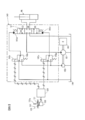
- the side view of a hydraulic excavator The figure which shows schematic structure of the hydraulic shovel which concerns on the 1st Embodiment of this invention.
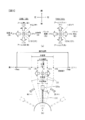
- (A) is a figure explaining operation
- (b) is a figure explaining the neutral range of an operation lever.
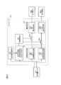
- the block diagram which shows the structure of the controller which concerns on the 1st Embodiment of this invention.
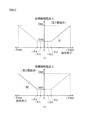
- (A) is a figure which shows the relationship between the operating angle (theta) of an operating lever, and the target value (refer solid line) of the control current output to a 1st solenoid valve
- (b) is the operating angle (theta) of an operating lever, and a 2nd solenoid valve
- the figure which shows the relationship with the target value (refer a continuous line) of the control current to output.
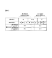
- the figure explaining the conditions for determining whether an electric current is supplied to a solenoid valve.
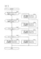
- the flowchart which shows an example of the process by the solenoid valve control program performed by the controller which concerns on the 1st Embodiment of this invention.
- (A) is a time chart which shows operation
- (b) is a time chart which shows operation
- (A) is a time chart which shows operation
- (b) is a time chart which shows operation
- the block diagram which shows the structure of the controller which concerns on the 2nd Embodiment of this invention.
- the flowchart which shows an example of the process by the solenoid valve control program performed by the controller which concerns on the 2nd Embodiment of this invention.
- FIG. 1 is a side view of a hydraulic excavator (backhoe) 100 which is an example of a work machine.
- a hydraulic excavator 100 includes a traveling body 101 and a revolving body 102 that is turnably mounted on the traveling body 101.
- the traveling body 101 travels by driving a pair of left and right crawlers by a traveling motor.
- a driver's cab 107 is provided on the left side of the front part of the swivel body 102, and an engine room is provided at the rear of the driver's cab 107.
- the engine room houses an engine, hydraulic equipment, and the like that are power sources.
- a counterweight 109 for balancing the airframe during work is attached to the rear of the engine compartment.
- a front working device 103 is provided on the right side of the front portion of the swivel body 102.
- the front working device 103 includes a plurality of front members, that is, a boom 104, an arm 105, and a bucket 106.
- the boom 104 is pivotally attached to the front part of the swing body 102 at the base end.
- One end of the arm 105 is rotatably attached to the tip of the boom 104.
- the boom 104 and the arm 105 are driven to rotate by the boom cylinder 104a and the arm cylinder 105a, respectively.
- the bucket 106 is attached at the tip of the arm 105 so as to be rotatable in the vertical direction with respect to the arm 105, and is driven to rotate by the bucket cylinder 106a.
- FIG. 2 is a diagram showing a schematic configuration of the hydraulic excavator 100 according to the first embodiment of the present invention.
- the hydraulic circuit included in the excavator 100 controls a plurality of hydraulic actuators such as a boom cylinder 104a, an arm cylinder 105a, a bucket cylinder 106a, a turning hydraulic motor, and a flow of pressure oil supplied to these hydraulic actuators.
- a solenoid valve device or the like is provided.
- one hydraulic actuator HA for example, bucket cylinder 106a
- FIG. 2 corresponds to a diagram showing a configuration for driving one hydraulic actuator (for example, bucket cylinder 106a).
- the hydraulic excavator 100 includes a controller 120, an engine 190, a main pump 151, a pilot pump 152, a solenoid valve device 140, and an operation device 130.
- the controller 120 includes an arithmetic processing unit having a CPU and a storage device such as ROM and RAM, and other peripheral circuits, and controls each part of the excavator 100.
- An operation amount sensor 133 is connected to the controller 120.
- the operation amount sensor 133 detects the rotation angle of the operation lever 131 of the operation device 130 as an operation angle (operation amount) ⁇ , and outputs a signal corresponding to the operation angle ⁇ to the controller 120.
- the operation amount sensor 133 for example, a potentiometer that outputs a voltage corresponding to the rotation angle of the operation lever 131 can be configured.
- the electric operation device 130 operates an electromagnetic valve device 140 described later, and includes an operation lever 131, an operation amount sensor 133, and a return mechanism including a return spring 132.
- the operating lever 131 is a rotatable rod-shaped member, and a grip portion 131a that is gripped by the operator is provided at the tip.
- a return spring 132 is connected to the operation lever 131, and the operation lever 131 is elastically biased toward the neutral position by the return spring 132.
- the return mechanism also has a function as a reaction force application device that applies an operation reaction force to the operation lever 131.
- a plurality of operating devices 130 are disposed in the cab 107.
- FIG. 3A is a view for explaining the operation of the excavator 100 corresponding to the operation direction of the operation lever 131.
- the operating device 130 a right operating device 130A located on the right side of the driver's seat and a left operating device 130B located on the left side of the driver's seat are provided.
- FIG. 3B is a diagram for explaining the neutral range of the operation lever 131.
- the neutral position (NP) of the operation lever 131 is set to a position that divides the rotation range of the operation lever 131 into two.
- the operation angle ⁇ of the operation lever 131 corresponds to an inclination angle from the neutral position (NP).
- the operation angle ⁇ when the operation lever 131 is located at the neutral position (NP) is set to 0 °.
- the operation angle ⁇ increases in the positive direction when tilted to one side from the neutral position (NP). Further, when the operation angle ⁇ is tilted from the neutral position (NP) to the other side, the operation angle ⁇ increases in the negative direction, that is, becomes smaller than 0 °.
- the right operation device 130A is an operation device that operates the rotation operation of the boom 104 with respect to the revolving structure 102 and the rotation operation of the bucket 106 with respect to the arm 105.
- the operating lever hereinafter referred to as the right operating lever 131A
- the boom lowering operation is an operation in which the boom cylinder 104a contracts and the boom 104 rotates downward at a speed corresponding to the operation angle ( ⁇ 1).
- the right operation lever 131A is tilted rearward from the neutral position (NP)
- the negative operation angle ( ⁇ 1) is decreased, and the boom raising operation is performed.
- the boom raising operation is an operation in which the boom cylinder 104a extends and the boom 104 rotates upward at a speed corresponding to the operation angle ( ⁇ 1).
- a bucket earthing operation (also called a bucket dump operation) is performed.
- the bucket earthing operation means that the bucket 106 rotates at a speed corresponding to the operation angle ( ⁇ 2) so that the bucket cylinder 106a contracts and the toe (tip) of the bucket 106 moves away from the abdominal surface of the arm 105 (FIG. 1). (Clockwise rotation).
- the negative operation angle ( ⁇ 2) decreases, and a bucket excavation operation (also referred to as a bucket cloud operation) is performed.
- the bucket excavation operation means that the bucket 106 rotates at a speed corresponding to the operation angle ( ⁇ 2) so that the bucket cylinder 106a extends and the tip of the bucket 106 approaches the abdominal surface of the arm 105 (in FIG. 1). (Rotating counterclockwise).
- the operation lever (hereinafter referred to as the left operation lever 131B) of the left operation device 130B is an operation member that operates the rotation operation of the arm 105 relative to the boom 104 and the rotation operation of the revolving structure 102.
- the left operation lever 131B is tilted forward from the neutral position (NP)
- the positive operation angle ( ⁇ 3) is increased
- an arm pushing operation also referred to as an arm extending operation
- the arm pushing operation means that the arm cylinder 105a contracts and the arm 105 rotates at a speed corresponding to the operation angle ( ⁇ 3) in the direction in which the relative angle of the arm 105 expands with respect to the boom 104 (clockwise in FIG. 1). To rotate).
- the arm pulling operation means that the arm 105 rotates at a speed corresponding to the operation angle ( ⁇ 3) so that the arm cylinder 105a extends and the arm 105 is folded to the boom 104 side (rotates counterclockwise in FIG. 1). Is) operation.
- the dead zone is an operation area where the hydraulic actuator HA corresponding to the operation lever 131 does not operate, and the hydraulic pressure is sharply increased only when the operation lever 131 is slightly tilted from the neutral position (NP). It is provided to prevent the actuator HA from being driven.
- the dead zone is set in a range where the operation angle is ( ⁇ d) or more and (+ ⁇ d) or less, for example, about 15 to 25% of the entire operation range. Note that ⁇ d is a positive number ( ⁇ d> 0).
- the neutral range is an operation region set in advance in the dead zone, and is provided for use in determining whether or not to supply a control current to the solenoid valve device 140.
- the neutral range is set such that the operation angle is not less than ( ⁇ n) and not more than (+ ⁇ n), and is, for example, about 5 to 10% of the entire operation range.
- ⁇ n is a positive number smaller than ⁇ d and is an angle threshold value representing the boundary of the neutral range ( ⁇ n ⁇ d).
- the first angle threshold (+ ⁇ n), which is a positive angle threshold, and the second angle threshold ( ⁇ n), which is a negative angle threshold, are stored in advance in the storage device of the controller 120.
- the controller 120 receives signals corresponding to the operation angles ⁇ ( ⁇ 1, ⁇ 2, ⁇ 3, ⁇ 4) of the left operation lever 131B and the right operation lever 131A.
- the controller 120 detects the operation direction and the operation angle of the left operation lever 131B and the right operation lever 131A based on the operation angle ⁇ signal from the operation amount sensor 133.
- the main pump 151 and the pilot pump 152 which are hydraulic pumps, are driven by the engine 190 and discharge the hydraulic oil in the tank 199 as pressure oil.
- the hydraulic actuator HA is driven by pressure oil discharged from the main pump 151.
- the electromagnetic valve device 140 includes a hydraulic pilot type directional control valve 141 that controls the flow of pressure oil supplied from the main pump 151 to the hydraulic actuator HA, and two electromagnetic proportional pressure reducing valves that control the operation of the directional control valve 141 ( Hereinafter, the first electromagnetic valve 142p and the second electromagnetic valve 142m) are provided.
- the first solenoid valve 142p is connected to the pilot pump 152, and generates a pilot pressure to be supplied to the first pilot portion 141p of the direction control valve 141 when the operation lever 131 is rotated to the positive side outside the neutral range.
- the second electromagnetic valve 142m is connected to the pilot pump 152, and generates a pilot pressure to be supplied to the second pilot portion 141m of the direction control valve 141 when the operation lever 131 is turned to the negative side outside the neutral range. To do.
- the hydraulic actuator HA in FIG. 2 is described as a bucket cylinder 106a, and the driving of the bucket 106 will be representatively described.
- the controller 120 outputs a control current (excitation current) to the solenoids 143p and 143m of the electromagnetic valves 142p and 142m according to the operation direction and operation angle of the operation lever 131.
- the degree of pressure reduction of the first electromagnetic valve 142p is set by the control current supplied from the controller 120 according to the operation angle ( ⁇ ).
- the degree of pressure reduction of the second electromagnetic valve 142m is set by the control current supplied from the controller 120 according to the operation angle ( ⁇ ).
- the opening characteristics of the solenoid valves 142p and 142m are such that the degree of pressure reduction decreases with increasing control current input to the solenoids 143p and 143m, that is, the secondary pressure (pilot pressure) increases with increasing control current. Is set to
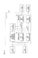
- FIG. 4 is a block diagram showing the configuration of the controller 120 according to the first embodiment of the present invention.
- the controller 120 includes a target current determination unit 122, a current supply unit 123, an operation speed calculation unit 127, a condition determination unit 128, and a current control unit 129.
- a power supply device (not shown) is connected to the controller 120.
- the current supply unit 123 includes a first current supply unit 123a that supplies current to the solenoid 143p of the first electromagnetic valve 142p that constitutes the electromagnetic valve device 140 when the operation lever 131 is rotated to the positive side. .
- the current supply unit 123 includes a second current supply unit 123b that supplies a current to the solenoid 143m of the second electromagnetic valve 142m constituting the electromagnetic valve device 140 when the operation lever 131 is turned to the negative side. .
- the current supply unit 123 adjusts the magnitude of the control current based on the target value of the control current set by the target current determination unit 122, which will be described later, and supplies the control current to each solenoid 143p, 143m.
- the current supply unit 123 does not supply current to the electromagnetic valves 142p and 142m.
- the target current determination unit 122 is a target value of the control current supplied from the current supply unit 123 to the solenoids 143p and 143m of the electromagnetic valves 142p and 142m based on the operation angle ⁇ of the operation lever 131 detected by the operation amount sensor 133. To decide.
- the target current determination unit 122 includes a first target current determination unit 122a and a second target current determination unit 122b.
- FIG. 5A is a diagram showing the relationship between the operating angle ⁇ of the operating lever 131 and the target value (see solid line) of the control current output to the first electromagnetic valve 142p
- FIG. It is a figure which shows the relationship between the operation angle (theta) and the target value (refer solid line) of the control current output to the 2nd solenoid valve 142m.
- a characteristic N1 shown in FIG. 5A and a characteristic N2 shown in FIG. 5B are stored in a lookup table format.
- the first target current determination unit 122a refers to the table of the characteristic N1 indicated by the solid line in FIG. 5A, and based on the operation angle ⁇ detected by the operation amount sensor 133, moves to the solenoid 143p of the first electromagnetic valve 142p.
- a target value (target control current It) of the control current to be output is set.
- the target control current It is set to the minimum current Imin.
- the target control current It increases linearly as the operation angle ⁇ increases.
- the target control current It is set to the maximum current Imax.
- the second target current determination unit 122b refers to the table of the characteristic N2 indicated by the solid line in FIG. 5B, and based on the operation angle ⁇ detected by the operation amount sensor 133, the second electromagnetic valve 142m A target value (target control current It) of the control current output to the solenoid 143m is set.
- the target control current It is set to the minimum current Imin.
- the operation angle ⁇ decreases, that is, the absolute value
- the target control current It is set to the maximum current Imax.
- the maximum current Imax is a target value for minimizing the degree of pressure reduction of the solenoid valves 142p, 142m.
- the minimum current Imin is a target value for causing the electromagnetic valve device 140 to supply a standby current when the operation lever 131 is disposed within the neutral range.
- the minimum current Imin is also referred to as a standby current Imin.
- the standby current Imin is a very small current of about 10 mA to 400 mA, for example, and is lower than the current when the hydraulic actuator HA starts driving, in other words, lower than the current when the spool of the directional control valve 141 starts operation. is there.
- the standby current is dithered at a predetermined frequency in the current supply unit 123. For this reason, when a standby current is supplied to the solenoids 143p and 143m of the electromagnetic valves 142p and 142m, the spools of the electromagnetic valves 142p and 142m vibrate slightly, thereby reducing the friction of the sliding portion and making it easy to start. Become.
- the operation speed calculation unit 127 calculates an operation speed (angular velocity) ⁇ of the operation lever 131 based on the operation angle ⁇ of the operation lever 131 detected by the operation amount sensor 133.
- the operation speed calculator 127 repeatedly calculates the operation speed ⁇ every predetermined control period (for example, about 1 ms to 10 ms).
- ( ⁇ ⁇ / ⁇ t)
- the operation speed calculation unit 127 calculates the operation speed ⁇ that is the time change rate of the operation angle ⁇ by differentiating the operation angle ⁇ with respect to time.
- the condition determination unit 128 determines whether the first electromagnetic valve validation condition is satisfied, and It is determined whether the second electromagnetic valve validation condition is satisfied.
- FIG. 6 is a diagram for explaining conditions for determining whether or not to supply current to the electromagnetic valves 142p and 142m.
- the condition determination unit 128 is an operation intention determination unit that determines whether the operator intends to operate the operation lever 131 based on the operation speed ⁇ that is the time change rate of the operation angle ⁇ of the operation lever 131.
- condition determination unit 128 has a function as an operation position determination unit that determines whether the operation lever 131 is disposed within a preset neutral range based on the operation angle ⁇ of the operation lever 131. ing.
- condition determination unit 128 will be described in detail.
- the condition determination unit 128 determines that the first electromagnetic valve activation condition is satisfied when the use of the first electromagnetic valve 142p is specified when the operation lever 131 is disposed on the positive side outside the neutral range.
- the condition determination unit 128 determines that the operation lever 131 is disposed on the positive side outside the neutral range.
- the condition determination unit 128 When it is determined that the operation lever 131 is disposed within the neutral range and the operation lever 131 is intended to operate in the bucket discharging direction (positive side), the condition determination unit 128 Assuming that the use of 142p is estimated, it is determined that the first electromagnetic valve validation condition is satisfied. When the absolute value
- the condition determination unit 128 determines that the second electromagnetic valve activation condition is satisfied when the use of the second electromagnetic valve 142m is specified when the operation lever 131 is disposed on the negative side outside the neutral range.
- the condition determination unit 128 determines that the operation lever 131 is disposed on the negative side outside the neutral range.
- the condition determination unit 128 determines that the second electromagnetic valve 142m It is determined that the second electromagnetic valve validation condition is satisfied.
- the condition determination unit 128 determines that there is an intention to operate the operation lever 131 in the bucket excavation direction (negative side).
- the condition determination unit 128 activates the first solenoid valve and the second solenoid valve. It is determined that none of the conditions are satisfied.
- the condition determination unit 128 does not intend to operate the operation lever 131 when the operation speed ⁇ of the operation lever 131 is larger than the second speed threshold ( ⁇ i) and smaller than the first speed threshold (+ ⁇ i). Is determined.
- the first speed threshold (+ ⁇ i), which is a positive speed threshold, and the second speed threshold ( ⁇ i), which is a negative speed threshold, are stored in advance in the storage device of the controller 120.
- ⁇ i is a positive number and is a speed threshold value for determining whether or not the operation lever 131 is stopped.
- ⁇ i is a value slightly larger than 0 ( ⁇ i> 0).
- the condition determination unit 128 determines that there is no intention to operate the operation lever 131 when the absolute value
- the current control unit 129 outputs an enabling signal to the first switch 126 a and outputs an invalidating signal to the second switch 126 b when the first solenoid valve enabling condition is satisfied.
- the first switch 126a permits a signal corresponding to the target control current It set by the first target current determination unit 122a to be supplied to the first current supply unit 123a.
- the second switch 126b prohibits a signal corresponding to the target control current It set by the second target current determination unit 122b from being supplied to the second current supply unit 123b.
- the current control unit 129 permits, that is, enables the control current to be supplied from the first current supply unit 123a to the first electromagnetic valve 142p that is estimated or specified to be used.
- the current control unit 129 prohibits, that is, invalidates the supply of the control current from the second current supply unit 123b to the second electromagnetic valve 142m that is not estimated or specified to be used.
- the current control unit 129 outputs an invalidation signal to the first switch 126 a and outputs an validation signal to the second switch 126 b when the second electromagnetic valve validation condition is satisfied.
- the second switch 126b permits a signal corresponding to the target control current It set by the second target current determination unit 122b to be supplied to the second current supply unit 123b.
- the first switch 126a prohibits a signal corresponding to the target control current It set by the first target current determination unit 122a from being supplied to the first current supply unit 123a.
- the current control unit 129 permits, that is, enables the control current to be supplied from the second current supply unit 123b to the second electromagnetic valve 142m that is estimated or specified to be used.
- the current control unit 129 prohibits, that is, invalidates the supply of the control current from the first current supply unit 123a to the first electromagnetic valve 142p that is not estimated or specified to be used.
- the current control unit 129 outputs an invalidation signal to each of the first switch 126a and the second switch 126b when neither the first solenoid valve validation condition nor the second solenoid valve validation condition is satisfied. Accordingly, the first switch 126a and the second switch 126b are prohibited from supplying a signal corresponding to the target control current It to each of the first current supply unit 123a and the second current supply unit 123b. That is, the current control unit 129 is supplied from the first current supply unit 123a and the second current supply unit 123b to each of the first electromagnetic valve 142p and the second electromagnetic valve 142m that are not estimated or specified to be used. Prohibit the supply of control current, ie disable it.
- the current is allowed to be supplied from the first current supply unit 123a to the first electromagnetic valve 142p (the first electromagnetic valve is on), and the second Supply of current from the current supply unit 123b to the second electromagnetic valve 142m is prohibited (second electromagnetic valve off).
- the second electromagnetic valve validation condition is satisfied, the current is prohibited from being supplied from the first current supply unit 123a to the first electromagnetic valve 142p (the first electromagnetic valve is off), and the second current supply unit 123b is set to the second state. Supply of current to the solenoid valve 142m is permitted (second solenoid valve on).
- FIG. 7 is a flowchart showing an example of processing by the solenoid valve control program executed by the controller 120 according to the first embodiment of the present invention.
- the process shown in the flowchart of FIG. 7 is started when an ignition switch (not shown) is turned on, and after initial settings (not shown), the processes after step S110 are performed every predetermined control period (for example, about 1 ms to 10 ms). Are repeatedly executed by the controller 120.
- the controller 120 acquires information on the operation angle ⁇ detected by the operation amount sensor 133 for each predetermined control cycle.
- the controller when the controller outputs an on signal to the solenoid valve, it means that the controller permits the current to be supplied to the solenoid valve, and when the controller outputs an off signal to the solenoid valve, the controller It means prohibiting the supply of current to the solenoid valve.
- step S110 the controller 120 calculates the operation speed ⁇ based on the operation angle ⁇ detected by the operation amount sensor 133, and proceeds to step S120.
- step S120 the controller 120 determines that the absolute value
- step S125 the controller 120 outputs an ON signal to the first electromagnetic valve 142p, outputs an OFF signal to the second electromagnetic valve 142m, and ends the process shown in the flowchart of FIG.
- step S130 the controller 120 determines that the absolute value
- step S135 the controller 120 outputs an off signal to the first electromagnetic valve 142p, outputs an on signal to the second electromagnetic valve 142m, and ends the processing shown in the flowchart of FIG.
- step S140 the controller 120 determines whether or not the operation angle ⁇ is smaller than the second angle threshold ( ⁇ n). If an affirmative determination is made in step S140, the process proceeds to step S145, and if a negative determination is made in step S140, the process proceeds to step S150.
- step S145 the controller 120 outputs an off signal to the first electromagnetic valve 142p, outputs an on signal to the second electromagnetic valve 142m, and ends the processing shown in the flowchart of FIG.
- step S150 the controller 120 determines whether or not the operation angle ⁇ is larger than the first angle threshold (+ ⁇ n). If an affirmative determination is made in step S150, the process proceeds to step S155, and if a negative determination is made in step S150, the process proceeds to step S160.
- step S155 the controller 120 outputs an ON signal to the first electromagnetic valve 142p, outputs an OFF signal to the second electromagnetic valve 142m, and ends the processing shown in the flowchart of FIG.
- step S160 the controller 120 outputs an off signal to the first electromagnetic valve 142p, outputs an off signal to the second electromagnetic valve 142m, and ends the processing shown in the flowchart of FIG.
- the glass swinging work refers to work that quickly shakes the bucket 106 to distribute earth and sand, concrete pieces, iron materials, and the like in the bucket 106.
- the dumping operation and the cloud operation are alternately repeated in the rattling operation.
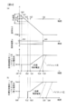
- FIG. 8A is a time chart showing the operation of the controller 120 according to the present embodiment
- FIG. 8B is a time chart showing the operation of the controller according to the comparative example.
- the horizontal axis in FIG. 8 indicates the elapsed time.
- the upper graph in FIG. 8A shows the time change of the operation angle ⁇
- the middle graph shows the time change of the operation speed ⁇
- the lower graph shows the time change of the target control current It with respect to the first electromagnetic valve 142p. Show.
- the lower graph of FIG. 8 (a) the change with time of the pilot pressure generated by the first electromagnetic valve 142p is also shown by a broken line.
- FIG. 8B is a diagram similar to the lower graph of FIG.
- the controller according to the comparative example prohibits the supply of the control current to the solenoid valve when the operation lever 131 is disposed within the neutral range regardless of the operation speed ⁇ . When it is arranged outside the neutral range, the control current is allowed to be supplied to the solenoid valve.
- the operator does not touch the operation lever 131, and the operation lever 131 is in a non-operation state.
- the operation speed ⁇ increases (time ta1).
- the operation speed ⁇ increases, the above-described first solenoid valve validation condition is satisfied (Yes in step S120), and therefore, the standby current Imin is supplied to the first solenoid valve 142p.
- the target control current It increases as the operating angle ⁇ increases (time ta3 to time ta5). Since the control current supplied to the first electromagnetic valve 142p increases, the pilot pressure increases from time ta4. When the operation lever 131 is operated up to the maximum operation angle (+ ⁇ max) at time ta5, the operation speed ⁇ becomes zero.
- the standby current Imin is not supplied to the first electromagnetic valve 142p while the operation lever 131 is located within the neutral range (time ta0 to time ta2).
- the standby current Imin is supplied to the first electromagnetic valve 142p when the operation lever 131 is positioned within the dead zone outside the neutral range (time ta2 to time ta3).
- the standby current Imin supply start timing (time point ta2) is later than in the present embodiment, and therefore the standby current application time is short.
- the pilot pressure increase start timing (time point ta6) is delayed as compared with the present embodiment.
- the operation lever 131 even when the operation lever 131 is positioned within the neutral range, it is determined that the operator intends to operate the operation lever 131 in the bucket discharging direction (positive direction).
- the first electromagnetic valve 142p is estimated to be used, and the standby current Imin is supplied to the first electromagnetic valve 142p.
- the supply timing of the standby current Imin is earlier than in the comparative example (time ta1 ⁇ time ta2). That is, the standby current application time can be sufficiently secured, and the friction inside the solenoid valve can be shifted from static friction to dynamic friction.
- the pilot pressure increase start timing is earlier than in the comparative example (time ta4 ⁇ time ta6).
- FIG. 9A is a time chart showing the operation of the controller 120 according to the present embodiment
- FIG. 9B is a time chart showing the operation of the controller according to the comparative example.
- FIG. 9 is a diagram similar to FIG. 8, and the horizontal axis of FIG. 9 indicates the elapsed time.
- the upper graph in FIG. 9A shows the time change of the operation angle ⁇
- the middle graph shows the time change of the operation speed ⁇
- the lower graph shows the time change of the target control current It for the second electromagnetic valve 142m. Show.
- the change over time of the pilot pressure generated by the second electromagnetic valve 142m is shown by a broken line.
- FIG. 9B is a diagram similar to the lower graph of FIG. 9A, and shows the time change of the target control current It and the time change of the pilot pressure.
- the cloud operation is performed after the above-described dump operation (see FIG. 8).
- the operator operates the operation lever 131 to the maximum operation angle (+ ⁇ max) in the bucket earthing direction, and then returns the operation lever 131 toward the neutral position.
- the operator operates the operation lever 131 at a constant operation speed ⁇ without reducing the operation speed ⁇ in order to operate the operation lever 131 in the bucket excavation direction beyond the neutral position.
- the control lever 131 is out of the neutral range and is located in the bucket discharging direction from the neutral position (NP). Is not supplied (Yes in step S150). If the operating lever 131 enters the neutral range while the absolute value
- the target control current It increases as the operation angle ⁇ increases (time tb3 to time tb5). Since the control current supplied to the second electromagnetic valve 142m increases, the pilot pressure increases from time tb4. When the operating lever 131 is operated up to the maximum operating angle ( ⁇ max) at time tb5, the operating speed ⁇ becomes zero.
- the standby current Imin is not supplied to the second electromagnetic valve 142m while the operation lever 131 is positioned within the neutral range (time tb0 to time tb2).
- the standby current Imin is supplied to the second electromagnetic valve 142m when the operation lever 131 is positioned within the dead zone outside the neutral range (time tb2 to time tb3).
- the standby current application time is short.
- the pilot pressure increase start timing (time point tb6) is delayed compared to the present embodiment.
- the current control unit 129 supplies the standby current Imin from the current supply unit 123 to the solenoid of the other solenoid valve on the positive side and the negative side.
- the standby current Imin is supplied to the second electromagnetic valve 142m.
- the supply timing of the standby current Imin is earlier than in the comparative example (time tb1 ⁇ time tb2). That is, the standby current application time can be sufficiently secured, and the friction inside the solenoid valve can be shifted from static friction to dynamic friction.
- the start timing of the increase in pilot pressure is earlier than in the comparative example (time tb4 ⁇ time tb6).
- FIG. 8 illustrates the case where the operation lever 131 is operated in the bucket discharging direction from the non-operation state, but the same applies to the case where the operation lever 131 is operated in the bucket excavation direction from the non-operation state.
- FIG. 9 the case where the operation in the bucket excavation direction is switched to the bucket excavation direction has been described, but the operation in the bucket excavation direction is switched to the bucket excavation direction. The same applies to the case.
- the electromagnetic valve device 140 that drives the bucket cylinder 106a has been described as a representative, but other hydraulic actuators such as the arm cylinder 105a, the boom cylinder 104a, and the swing motor are the same.
- the standby current is supplied when the controller 120 detects the operator's intention to operate the operation lever 131 in the neutral range. The responsiveness of the electromagnetic valve device and the hydraulic actuator to the operation can be improved.
- the hydraulic excavator 100 includes a main pump 151, a hydraulic actuator HA driven by pressure oil discharged from the main pump 151, and an electromagnetic for controlling the flow of pressure oil supplied from the main pump 151 to the hydraulic actuator HA.
- a valve device 140 and an operation device 130 for operating the electromagnetic valve device 140 are provided.
- the controller 120 includes a current supply unit 123 that supplies current to the solenoid of the electromagnetic valve device 140 based on the operation of the operation lever 131.
- the controller 120 intends to operate the operation lever 131 of the operation device 130 by the operator based on the change in the state of the operation lever 131 (in this embodiment, the operation speed ⁇ that is the time change rate of the operation angle ⁇ ).
- an operation intention determination unit for determining whether or not there is.
- the controller 120 controls the current supply from the current supply unit 123 to the electromagnetic valve device 140 based on the position of the operation lever 131 and the determination result of the operation intention determination unit (condition determination unit 128). It has. By supplying an electric current to the electromagnetic valve device 140 when the operator's intention of the operation is detected, the responsiveness of the electromagnetic valve device 140 to the operation can be improved.
- the controller 120 includes an operation position determination unit (condition determination unit 128) that determines whether or not the operation lever 131 is disposed within a preset neutral range.
- condition determination unit 1228 determines whether or not the operation lever 131 is disposed within a preset neutral range.
- the current control unit 129 is more than the current when the hydraulic actuator HA starts driving.
- the low standby current Imin is allowed to be supplied from the current supply unit 123 to the electromagnetic valve device 140.
- the standby current is supplied so that the responsiveness of the electromagnetic valve device 140 and the hydraulic actuator HA to the operation is supplied. Can be improved.
- the controller 120 determines that the standby current Imin is supplied from the current supply unit 123 to the solenoid valve device when it is determined that the operation lever 131 is disposed within the neutral range and there is no intention to operate the operation lever 131. 140 is prohibited. That is, when the operation lever 131 is located within the neutral range and the operator's intention for operation is not detected, the standby current is not supplied to the solenoid of the electromagnetic valve device 140. As a result, even when the calculation result of the target control current It becomes an abnormal value due to the mixing of noise between the controller 120 and the controller device 130, the operator moves the operation lever 131 to the neutral position. By returning, the hydraulic actuator HA can be stopped. That is, it is possible to prevent the hydraulic actuator HA from performing an operation different from the operator's intention.
- the operation speed calculator 127 calculates the operation speed ⁇ of the operation lever 131 based on the operation angle ⁇ of the operation lever 131.
- the condition determination unit 128 determines that there is an intention to operate the operation lever 131.
- the condition determination unit 128 determines that there is no intention to operate the operation lever 131.
- the operation lever 131 is configured to be rotatable from the neutral position (NP) in the neutral range to the positive side and the negative side.
- the electromagnetic valve device 140 includes a direction control valve 141, a first electromagnetic valve 142p, and a second electromagnetic valve 142m.
- the direction control valve 141 controls the flow of pressure oil supplied from the main pump 151 to the hydraulic actuator HA.
- the first electromagnetic valve 142p is a positive electromagnetic proportional pressure reduction that generates a pilot pressure to be supplied to the first pilot portion 141p of the direction control valve 141 when the operation lever 131 is rotated to the positive side outside the neutral range. It is a valve.
- the second electromagnetic valve 142m is a negative electromagnetic proportional pressure reduction that generates a pilot pressure to be supplied to the second pilot portion 141m of the direction control valve 141 when the operation lever 131 is turned to the negative side outside the neutral range. It is a valve.
- the current supply unit 123 supplies current to the solenoid 143p of the first electromagnetic valve 142p when the operation lever 131 is rotated to the positive side, and when the operation lever 131 is rotated to the negative side, A current is supplied to the solenoid 143m of the second electromagnetic valve 142m.
- the operation intention determination unit determines that the operation speed ⁇ is positive when the absolute value
- of the operation speed ⁇ toward the other of the positive side and the negative side from the state where the operation lever 131 is operated to one of the positive side and the negative side of the neutral range is the speed threshold value ⁇ i.
- the operation intention determination unit determines that there is an intention to operate on the other of the positive side and the negative side.
- the direction (the bucket earthing direction or the bucket excavation direction) in which the operation speed ⁇ is operated by positive and negative is determined.
- the solenoid valve on the side determined to have at least one of the positive side and the negative side to be operated from the current supply unit 123 The standby current is supplied to the solenoid.
- the operation lever 131 that is alternately operated in the first direction (positive direction) and the second direction (negative direction) that is opposite to the first direction.
- the operation of the opposite direction beyond the neutral position (NP) is predicted, and a standby current is supplied to the solenoid valve that is estimated to be used.
- the second electromagnetic valve 142m is The standby current can be supplied to the second electromagnetic valve 142m by presuming that it is used.
- the response of the hydraulic actuator HA can be improved in the case where the operation lever 131 such as a loose swing is quickly operated alternately in the first direction and the second direction (left and right in the present embodiment). Improvement of responsiveness contributes to improvement of work efficiency and operability.
- FIG. 10 is a diagram similar to FIG. 4, and is a block diagram showing a configuration of the controller 220 according to the second embodiment of the present invention. As shown in FIG. 10, the controller 220 receives a signal from a grip switch 233 provided in the grip portion 131 a of the operation lever 131.
- the grip switch 233 outputs an ON signal indicating that it is gripped when gripped by the operator, and outputs an OFF signal indicating that it is not gripped when not gripped by the operator.
- the condition determination unit 228 determines that there is no intention to operate the operation lever 131 when an off signal is output from the grip switch 233.
- the condition determination unit 228 When the operation lever 131 is positioned on the positive side in the neutral range and the ON signal is output from the grip switch 233, the condition determination unit 228 has an intention to operate the operation lever 131 in the positive direction. judge.
- the condition determination unit 228 has an intention to operate the operation lever 131 in the negative direction when the ON signal is output from the grip switch 233 with the operation lever 131 positioned on the negative side in the neutral range. Judged.
- FIG. 11 is a diagram similar to FIG. 7, and is a flowchart showing an example of processing by an electromagnetic valve control program executed by the controller 220 according to the second embodiment of the present invention.
- the process of step S110 in the flowchart of FIG. 7 is omitted, and the processes of steps S220 and 230 are executed instead of steps S120 and S130.
- the same processes as those shown in FIG. 7 are denoted by the same reference numerals, and the processes different from the processes shown in FIG. 7 will be mainly described.
- the processing shown in this flowchart is started by turning on an ignition switch (not shown), and after initial setting (not shown), the processing after step S220 is repeatedly executed by the controller 220 every predetermined control cycle.
- the controller 220 obtains information on the signal (ON / OFF signal) output from the grip switch 233 and information on the operation angle ⁇ detected by the operation amount sensor 133 for each predetermined control cycle. .
- step S220 the controller 220 determines whether or not the operation angle ⁇ is 0 ° or more and not more than the first angle threshold (+ ⁇ n) and an on signal is output from the grip switch 233. If an affirmative determination is made in step S220, the process proceeds to step S125, and if a negative determination is made in step S220, the process proceeds to step S230.
- step S230 the controller 220 determines whether or not the operation angle ⁇ is less than 0 ° and greater than or equal to the second angle threshold ( ⁇ n), and an ON signal is output from the grip switch 233. If a positive determination is made in step S230, the process proceeds to step S135, and if a negative determination is made in step S230, the process proceeds to step S140.
- the operation intention determination unit determines that there is an intention to operate the operation lever 131 when the ON signal is output from the grip switch 233. To do.
- the operation intention determination unit determines that there is no intention to operate the operation lever 131 when an off signal is output from the grip switch 233. According to such a second embodiment, the same operational effects as (1) to (3) described in the first embodiment can be obtained.
- an electromagnetically driven directional control valve 241 including solenoids 243p and 243m may be employed as the electromagnetic valve device 240 that drives a small hydraulic actuator HA.
- the first electromagnetic valve 142p and the second electromagnetic valve 142m are omitted.
- the spool of the direction control valve 241 moves to the position (D) side.
- a single electromagnetic proportional pressure reducing valve and a single electromagnetic switching valve may be provided instead of the first electromagnetic valve 142p and the second electromagnetic valve 142m.
- the pilot pressure is supplied to the first pilot portion 141p.
- the degree of pressure reduction of the electromagnetic proportional pressure reducing valve is set according to the operation amount, and the electromagnetic switching valve is switched to the other according to the operation direction.
- a pilot pressure is supplied to the pilot unit 141m.
- the standby current is supplied to both the electromagnetic proportional pressure reducing valve and the electromagnetic switching valve. According to such a modification, the same operational effects as those of the above-described embodiment can be obtained.
- the operation amount sensor 133 is configured by a potentiometer and the voltage corresponding to the rotation angle of the operation lever 131 is output.
- the present invention is not limited to this.
- an angle sensor using a Hall element may be adopted as the operation amount sensor 133.
- Information corresponding to the operation angle ⁇ may be acquired from a network in the hydraulic excavator 100 called CAN (Controller Area Network). In this case, the number of wirings can be suppressed and noise can be reduced.
- the operation angle ⁇ may be obtained using a PWM duty corresponding to the angle of the operation lever 131. In this case, noise can be reduced.
- the angle threshold value and the operation speed threshold value described above may have hysteresis.
- the first electromagnetic valve activation condition and the second electromagnetic valve activation condition are such that the above condition (steps S120, 130, 140, 150) is satisfied for a predetermined time (for example, about 2 to 3 times the control cycle). ) It may be determined that it has been established by continuing. As a result, even when transient noise is superimposed on the operation angle ⁇ and the operation speed ⁇ , it is possible to estimate or specify the electromagnetic valve to be used appropriately.
- the return mechanism including the return spring 132 has been described as an example, but the present invention is not limited to this. Instead of the return spring 132, a return mechanism including a cylinder in which a compressible gas such as air or nitrogen gas is sealed and has a damping characteristic and a spring characteristic may be employed.
- the current control unit 129 controls the first switch 126a and the second switch 126b between the target current determination unit 122 and the current supply unit 123, so that the current to the solenoid valves 142p and 142m is reduced.
- the first switch 126a and the second switch 126b may be provided between the current supply unit 123 and the electromagnetic valves 142p and 142m.
- the controller 120 described above may be implemented as part or all of the functions as software that operates on hardware, or may be realized only by hardware including an integrated circuit.
- Information such as programs, tables, and files executed by the controller 120 may be stored in a storage device such as a hard disk or SSD (Solid State Drive), or an IC card, SD card, DVD, or the like, instead of the above-described memory such as ROM or RAM. It may be stored in the storage medium.
- the target current determining unit 122 determines the target value for supplying the standby current when the operation lever 131 is disposed within the neutral range, and the operation lever 131 is disposed within the neutral range. If not, the target value for increasing the current supplied from the current supply unit 123 to the solenoids 143p and 143m as the operation amount of the operation lever 131 increases is determined. The current supply unit 123 supplies a current to the solenoid of the electromagnetic valve device 140 based on the target value.
- the current control unit 129 When it is determined that the operation lever 131 is disposed within the neutral range and there is no intention to operate the operation lever 131, the current control unit 129 receives the solenoids 143p, 143p of the electromagnetic valve device 140 from the current supply unit 123. It is prohibited to supply current to 143m. When it is determined that the operation lever 131 is disposed in the neutral range and the operation lever 131 is intended to operate the current control unit 129, the current control unit 129 receives the solenoid 143p, Allow current to be supplied to 143m.
- the calculation processing of the controller 120 is simplified by adopting a configuration that permits or prohibits current from being supplied to the solenoids 143p and 143m based on the target control current It determined by the target current determination unit 122.
- the present invention is not limited to this. For example, based on whether or not the operation intention is detected, first, determination of prohibition / permission of standby current supply is performed, and then the operation angle ⁇ is increased based on the determination result of whether or not standby current is supplied. A control current for driving the hydraulic actuator that increases with the calculation may be calculated.
- the speed threshold ⁇ i is a value slightly larger than 0 as a speed threshold for determining whether or not the operation lever 131 is stopped
- the speed threshold value ⁇ i is an operation that is performed quickly, such as a swinging operation of the bucket 106, and whether the operation lever 131 is operated suddenly in order to apply a standby current to an operation that requires high responsiveness. It is also possible to set an operation speed for determining whether or not. In this case, a somewhat large value is adopted as the speed threshold value ⁇ i.
- the crawler hydraulic excavator (backhoe) has been described as an example, but the present invention is not limited to this.
- the present invention can also be applied to, for example, a loading excavator and a wheeled hydraulic excavator.
- the present invention can be similarly applied to various work machines such as cranes and wheel loaders.
Landscapes
- Engineering & Computer Science (AREA)
- General Engineering & Computer Science (AREA)
- Physics & Mathematics (AREA)
- Mining & Mineral Resources (AREA)
- Civil Engineering (AREA)
- Structural Engineering (AREA)
- Fluid Mechanics (AREA)
- Mechanical Engineering (AREA)
- General Physics & Mathematics (AREA)
- Automation & Control Theory (AREA)
- Operation Control Of Excavators (AREA)
- Fluid-Pressure Circuits (AREA)
Abstract
操作に対する電磁弁装置の応答性を向上する。 作業機械は、油圧ポンプから油圧アクチュエータへ供給される圧油の流れを制御する電磁弁装置と、電磁弁装置を操作する操作部材と、操作部材が予め設定された中立範囲内に配置されているか否かを判定する操作位置判定部とを備えている。作業機械は、操作部材の状態の変化に基づいて、オペレータによる操作部材を操作しようとする意図があるか否かを判定する操作意図判定部と、操作部材の操作に基づいて電磁弁装置に電流を供給する電流供給部と、操作位置判定部により操作部材が中立範囲内に配置されていると判定され、かつ、操作意図判定部により操作部材を操作しようとする意図があると判定されているとき、油圧アクチュエータが駆動を開始するときの電流よりも低いスタンバイ電流が電流供給部から電磁弁装置に供給されることを許可する電流制御部と、を備えている。
Description
本発明は、作業機械に関する。
操作レバーの中立位置を検出する中立位置検出手段と、この中立位置検出手段の出力信号を入力し操作レバーが中立位置にあるときに制御手段の制御本体と制御弁との間の信号の伝達を禁止する禁止手段とを設けた油圧機械の駆動制御装置が知られている(特許文献1参照)。特許文献1に記載の駆動制御装置によれば、制御手段の制御本体を含む電気機器に故障、あるいは作業に伴うノイズの混入を生じ、誤信号が発生したとしても、その誤信号が制御弁に伝達されず、制御弁を中立位置に復帰させることができる。
しかしながら、特許文献1に記載の駆動制御装置では、油圧機械を動作させるために操作レバーを操作したとき、制御弁のスプールの摩擦の影響により、制御弁の応答遅れが大きいという問題がある。
本発明の一態様による作業機械は、油圧ポンプと、前記油圧ポンプから吐出される圧油によって駆動される油圧アクチュエータと、前記油圧ポンプから前記油圧アクチュエータへ供給される圧油の流れを制御する電磁弁装置と、前記電磁弁装置を操作する操作部材と、前記操作部材が予め設定された中立範囲内に配置されているか否かを判定する操作位置判定部とを備えた作業機械において、前記操作部材の状態の変化に基づいて、オペレータによる前記操作部材を操作しようとする意図があるか否かを判定する操作意図判定部と、前記操作部材の操作に基づいて前記電磁弁装置に電流を供給する電流供給部と、前記操作位置判定部により前記操作部材が中立範囲内に配置されていると判定され、かつ、前記操作意図判定部により前記操作部材を操作しようとする意図があると判定されているとき、前記油圧アクチュエータが駆動を開始するときの電流よりも低いスタンバイ電流が前記電流供給部から前記電磁弁装置に供給されることを許可する電流制御部と、を備えることを特徴とする。
本発明によれば、操作に対する電磁弁装置の応答性を向上できる。
-第1の実施の形態-
図1は、作業機械の一例である油圧ショベル(バックホウ)100の側面図である。なお、説明の便宜上、図1に示したように前後および上下方向を規定する。図1に示すように、油圧ショベル100は、走行体101と、走行体101上に旋回可能に搭載された旋回体102とを備える。走行体101は、左右一対のクローラを走行モータによって駆動することにより走行する。
図1は、作業機械の一例である油圧ショベル(バックホウ)100の側面図である。なお、説明の便宜上、図1に示したように前後および上下方向を規定する。図1に示すように、油圧ショベル100は、走行体101と、走行体101上に旋回可能に搭載された旋回体102とを備える。走行体101は、左右一対のクローラを走行モータによって駆動することにより走行する。
旋回体102の前部左側には運転室107が設けられ、運転室107の後部にはエンジン室が設けられている。エンジン室には、動力源であるエンジンや油圧機器等が収容されている。エンジン室の後部には、作業時の機体のバランスをとるためのカウンタウエイト109が取り付けられている。旋回体102の前部右側にはフロント作業装置103が設けられている。
フロント作業装置103は、複数のフロント部材、すなわちブーム104、アーム105、および、バケット106を備えている。ブーム104は、基端部が旋回体102の前部に回動可能に取り付けられている。アーム105は、その一端がブーム104の先端に回動可能に取り付けられている。ブーム104およびアーム105は、ブームシリンダ104aおよびアームシリンダ105aによってそれぞれ駆動されて回動する。バケット106は、アーム105の先端において、アーム105に対して上下方向に回動可能に取り付けられ、バケットシリンダ106aによって駆動されて回動する。
図2は、本発明の第1の実施の形態に係る油圧ショベル100の概略構成を示す図である。図2では、油圧回路の最高圧力を規定するリリーフバルブの図示は省略している。油圧ショベル100が備える油圧回路には、ブームシリンダ104aやアームシリンダ105a、バケットシリンダ106a、旋回用の油圧モータなどの複数の油圧アクチュエータや、これらの油圧アクチュエータへ供給される圧油の流れを制御する電磁弁装置等が設けられている。以下では、説明の便宜上、複数の油圧アクチュエータのうち、一の油圧アクチュエータHA(たとえば、バケットシリンダ106a)を代表して示し、その他の油圧アクチュエータについては図示を省略している。つまり、図2は、一の油圧アクチュエータ(たとえば、バケットシリンダ106a)を駆動するための構成を示す図に相当する。
油圧ショベル100は、コントローラ120と、エンジン190と、メインポンプ151と、パイロットポンプ152と、電磁弁装置140と、操作装置130と、を備えている。コントローラ120は、CPUや記憶装置であるROMおよびRAM、その他の周辺回路などを有する演算処理装置を含んで構成され、油圧ショベル100の各部の制御を行っている。
コントローラ120には、操作量センサ133が接続されている。操作量センサ133は、操作装置130の操作レバー131の回動角度を操作角(操作量)θとして検出し、操作角θに相当する信号をコントローラ120に出力する。操作量センサ133としては、たとえば、操作レバー131の回動角度に応じた電圧を出力するポテンショメータにより構成できる。電気式の操作装置130は、後述の電磁弁装置140を操作するものであって、操作レバー131と、操作量センサ133と、戻しばね132を含む復帰機構とを備えている。
操作レバー131は、回動可能な棒状の部材であって、先端部にはオペレータが把持する把持部131aが設けられている。操作レバー131には戻しばね132が接続されており、操作レバー131は中立位置に向かって戻しばね132により弾性的に付勢されている。なお、復帰機構は、操作レバー131に操作反力を付与する反力付与装置としての機能も有する。運転室107内には、複数の操作装置130が配設されている。
図3(a)は操作レバー131の操作方向に対応する油圧ショベル100の動作を説明する図である。運転室107内には、操作装置130として、運転席の右側に位置する右側操作装置130Aと、運転席の左側に位置する左側操作装置130Bとを備えている。
図3(b)は操作レバー131の中立範囲について説明する図である。図3(b)に示すように、操作レバー131の中立位置(NP)は、操作レバー131の回動範囲を2分する位置に設定されている。操作レバー131の操作角θは、中立位置(NP)からの傾き角に相当する。
本実施の形態では、中立位置(NP)に操作レバー131が位置しているときの操作角θは0°に設定されている。操作角θは、中立位置(NP)から一方に傾けると正の方向に大きくなる。また、操作角θは、中立位置(NP)から他方に傾けると負の方向に大きくなる、すなわち0°よりも小さくなる。
図3(a)に示すように、右側操作装置130Aは、旋回体102に対するブーム104の回動動作、および、アーム105に対するバケット106の回動動作を操作する操作装置である。右側操作装置130Aの操作レバー(以下、右操作レバー131Aと記す)を中立位置(NP)から前方に傾けると、正の操作角(θ1)が増加し、ブーム下げ動作が行われる。ブーム下げ動作とは、ブームシリンダ104aが収縮し、ブーム104が操作角(θ1)に応じた速度で下方に回動する動作である。右操作レバー131Aを中立位置(NP)から後方に傾けると、負の操作角(θ1)が減少し、ブーム上げ動作が行われる。ブーム上げ動作とは、ブームシリンダ104aが伸長し、ブーム104が操作角(θ1)に応じた速度で上方に回動する動作である。
右操作レバー131Aを中立位置(NP)から右方に傾けると、正の操作角(θ2)が増加し、バケット放土動作(バケットダンプ動作とも呼ばれる)が行われる。バケット放土動作とは、バケットシリンダ106aが収縮し、バケット106の爪先(先端)がアーム105の腹面から離れるように、バケット106が操作角(θ2)に応じた速度で回動する(図1において時計回りに回動する)動作である。右操作レバー131Aを中立位置(NP)から左方に傾けると、負の操作角(θ2)が減少し、バケット掘削動作(バケットクラウド動作とも呼ばれる)が行われる。バケット掘削動作とは、バケットシリンダ106aが伸長し、バケット106の爪先(先端)がアーム105の腹面に近づくように、バケット106が操作角(θ2)に応じた速度で回動する(図1において反時計回りに回動する)動作である。
左側操作装置130Bの操作レバー(以下、左操作レバー131Bと記す)は、ブーム104に対するアーム105の回動動作、および、旋回体102の旋回動作を操作する操作部材である。左操作レバー131Bを中立位置(NP)から前方に傾けると、正の操作角(θ3)が増加し、アーム押し動作(アーム伸ばし動作とも呼ばれる)が行われる。アーム押し動作とは、アームシリンダ105aが収縮し、ブーム104に対し、アーム105の相対角度が広がる方向に、アーム105が操作角(θ3)に応じた速度で回動する(図1において時計回りに回動する)動作である。左操作レバー131Bを中立位置(NP)から後方に傾けると、負の操作角(θ3)が減少し、アーム引き動作(アーム曲げ動作とも呼ばれる)が行われる。アーム引き動作とは、アームシリンダ105aが伸長し、アーム105をブーム104側に折りたたむように、アーム105が操作角(θ3)に応じた速度で回動する(図1において反時計回りに回動する)動作である。
左操作レバー131Bを中立位置(NP)から右方に傾けると、正の操作角(θ4)が増加し、旋回モータ(不図示)が駆動され、旋回体102が操作角(θ4)に応じた速度で右旋回する。左操作レバー131Bを中立位置(NP)から左方に傾けると、負の操作角(θ4)が減少し、旋回モータ(不図示)が駆動され、旋回体102が操作角(θ4)に応じた速度で左旋回する。なお、上述した、θ1,θ2,θ3,θ4を総称してθと記す。
右操作レバー131Aを中立位置(NP)から左斜め前方などの斜め方向に傾けると、ブーム104とバケット106を複合的に動作させることができる。左操作レバー131Bを中立位置(NP)から左斜め前方などの斜め方向に傾けると、アーム105と旋回体102を複合的に動作させることができる。このため、本実施の形態における油圧ショベル100では、右操作レバー131Aおよび左操作レバー131Bを同時に操作することで、最大、4つの動作を複合的に行わせることができる。
図3(b)に示すように、不感帯は、操作レバー131に対応する油圧アクチュエータHAが動作しない操作領域であり、操作レバー131が中立位置(NP)からわずかに傾動されただけで鋭敏に油圧アクチュエータHAが駆動されてしまうことを防止するために設けられている。不感帯は、操作角が(-θd)以上かつ(+θd)以下の範囲に設定されており、たとえば全操作範囲の15~25%程度である。なお、θdは、正の数である(θd>0)。
中立範囲は、不感帯内に予め設定される操作領域であり、制御電流を電磁弁装置140に供給するか否かの判定に用いるために設けられている。中立範囲は、操作角が(-θn)以上かつ(+θn)以下の範囲に設定されており、たとえば全操作範囲の5~10%程度である。なお、θnは、θdよりも小さい正の数であり、中立範囲の境界を表す角度閾値である(θn<θd)。正の角度閾値である第1角度閾値(+θn)、および、負の角度閾値である第2角度閾値(-θn)は、予めコントローラ120の記憶装置に記憶されている。
コントローラ120には、左操作レバー131Bおよび右操作レバー131Aの操作角θ(θ1,θ2,θ3,θ4)に相当する信号が入力される。コントローラ120は、操作量センサ133からの操作角θの信号に基づいて、左操作レバー131Bおよび右操作レバー131Aの操作方向および操作角を検出する。
図2に示すように、油圧ポンプであるメインポンプ151およびパイロットポンプ152は、エンジン190によって駆動され、タンク199内の作動油を圧油として吐出する。油圧アクチュエータHAは、メインポンプ151から吐出される圧油によって駆動される。電磁弁装置140は、メインポンプ151から油圧アクチュエータHAへ供給される圧油の流れを制御する油圧パイロット式の方向制御弁141と、方向制御弁141の動作を制御する2つの電磁比例減圧弁(以下、第1電磁弁142pおよび第2電磁弁142mと記す)と、を備えている。
第1電磁弁142pは、パイロットポンプ152に接続され、操作レバー131が中立範囲外の正側に回動操作されたときに、方向制御弁141の第1パイロット部141pへ供給するパイロット圧を生成する。第2電磁弁142mは、パイロットポンプ152に接続され、操作レバー131が中立範囲外の負側に回動操作されたときに、方向制御弁141の第2パイロット部141mへ供給するパイロット圧を生成する。
以下では、図2の油圧アクチュエータHAは、バケットシリンダ106aであるものとして、バケット106の駆動を代表して説明する。コントローラ120は、操作レバー131の操作方向および操作角に応じて、電磁弁142p,142mのソレノイド143p,143mに制御電流(励磁電流)を出力する。操作レバー131が正の方向(バケット放土方向)に操作された場合、操作角(θ)に応じてコントローラ120から供給される制御電流によって第1電磁弁142pの減圧度が設定される。操作レバー131が負の方向(バケット掘削方向)に操作された場合、操作角(θ)に応じてコントローラ120から供給される制御電流によって第2電磁弁142mの減圧度が設定される。
電磁弁142p,142mの開口特性は、ソレノイド143p,143mに入力される制御電流の増加に伴い減圧度が小さくなるように、すなわち制御電流の増加に伴い2次圧力(パイロット圧)が大きくなるように設定されている。
方向制御弁141の第1パイロット部141pに電磁弁142pで生成されたパイロット圧が作用すると、方向制御弁141のスプールが位置(D)側に移動し、油圧アクチュエータHA(バケットシリンダ106a)が収縮する。方向制御弁141の第2パイロット部141mに電磁弁142mで生成されたパイロット圧が作用すると、方向制御弁141のスプールが位置(C)側に移動し、油圧アクチュエータHA(バケットシリンダ106a)が伸長する。
方向制御弁141の第1パイロット部141pおよび第2パイロット部141mのそれぞれが、第1電磁弁142pおよび第2電磁弁142mのそれぞれを介してタンク199に接続されると、方向制御弁141のスプールは中立位置(N)に移動する。
図4は、本発明の第1の実施の形態に係るコントローラ120の構成を示すブロック図である。コントローラ120は、目標電流決定部122と、電流供給部123と、操作速度演算部127と、条件判定部128と、電流制御部129と、を備えている。コントローラ120には、図示しない電源装置が接続されている。電流供給部123は、操作レバー131が正側に回動操作されたときに電磁弁装置140を構成する第1電磁弁142pのソレノイド143pに電流を供給する第1電流供給部123aを備えている。電流供給部123は、操作レバー131が負側に回動操作されたときに電磁弁装置140を構成する第2電磁弁142mのソレノイド143mに電流を供給する第2電流供給部123bを備えている。電流供給部123は、後述する目標電流決定部122により設定される制御電流の目標値に基づき、制御電流の大きさを調節し、各ソレノイド143p,143mに供給する。なお、後述する目標電流決定部122により決定される制御電流の目標値に相当する信号がスイッチ126a,126bにより遮断されているとき、電流供給部123は電磁弁142p,142mに電流を供給しない。
目標電流決定部122は、操作量センサ133で検出された操作レバー131の操作角θに基づいて、電流供給部123から電磁弁142p,142mのソレノイド143p,143mへ供給される制御電流の目標値を決定する。目標電流決定部122は、第1目標電流決定部122aと第2目標電流決定部122bを備えている。
図5(a)は操作レバー131の操作角θと第1電磁弁142pへ出力する制御電流の目標値(実線参照)との関係を示す図であり、図5(b)は操作レバー131の操作角θと第2電磁弁142mへ出力する制御電流の目標値(実線参照)との関係を示す図である。コントローラ120の記憶装置には、図5(a)に示す特性N1および図5(b)に示す特性N2がルックアップテーブル形式で記憶されている。
第1目標電流決定部122aは、図5(a)の実線で示す特性N1のテーブルを参照し、操作量センサ133で検出された操作角θに基づいて、第1電磁弁142pのソレノイド143pへ出力する制御電流の目標値(目標制御電流It)を設定する。操作レバー131の操作角θが0以上かつ不感帯用第1閾値(+θd)以下の不感帯に位置しているときには、目標制御電流Itは最小電流Iminに設定される。操作角θが不感帯用第1閾値(+θd)よりも大きく、かつ正側最大操作角(+θmax)以下の操作帯では、操作角θが増加するほど、目標制御電流Itが直線的に増加する。操作レバー131の操作角θが正側最大操作角(+θmax)となっているときには、目標制御電流Itは最大電流Imaxに設定される。
同様に、第2目標電流決定部122bは、図5(b)の実線で示す特性N2のテーブルを参照し、操作量センサ133で検出された操作角θに基づいて、第2電磁弁142mのソレノイド143mへ出力する制御電流の目標値(目標制御電流It)を設定する。操作レバー131の操作角θが0以下かつ不感帯用第2閾値(-θd)以上の不感帯に位置しているときには、目標制御電流Itは最小電流Iminに設定される。操作角θが不感帯用第2閾値(-θd)未満、かつ負側最大操作角(-θmax)以上の操作帯では、操作角θの減少、すなわち操作角θの絶対値|θ|の増加するほど、目標制御電流Itが直線的に増加する。操作レバー131の操作角θが負側最大操作角(-θmax)となっているときには、目標制御電流Itは最大電流Imaxに設定される。
最大電流Imaxは、電磁弁142p,142mの減圧度を最小とするための目標値である。最小電流Iminは、操作レバー131が中立範囲内に配置されているときに電磁弁装置140にスタンバイ電流を供給させるための目標値である。以下、最小電流Iminをスタンバイ電流Iminとも記す。
スタンバイ電流Iminは、たとえば10mA~400mA程度の微小電流であり、油圧アクチュエータHAが駆動を開始するときの電流、換言すれば方向制御弁141のスプールが動作を開始するときの電流よりも低い電流である。なお、スタンバイ電流は、電流供給部123において、所定の周波数でディザがかけられる。このため、電磁弁142p,142mのソレノイド143p,143mにスタンバイ電流が供給されると、電磁弁142p,142mのスプールが微振動することにより、摺動部の摩擦が削減され、始動しやすい状態となる。
図4に示す操作速度演算部127は、操作量センサ133で検出された操作レバー131の操作角θに基づいて、操作レバー131の操作速度(角速度)ωを演算する。操作速度演算部127は、所定の制御周期(たとえば、1ms~10ms程度)ごとに繰り返し、操作速度ωを演算する。操作速度ωは、現制御周期で検出された操作角θbと、1制御周期前に検出された操作角θaとの差Δθ(=θb-θa)を、1制御周期に対応する時間Δtで除することで演算される(ω=Δθ/Δt)。換言すれば、操作速度演算部127は、操作角θを時間微分して、操作角θの時間変化率である操作速度ωを演算する。
条件判定部128は、操作速度演算部127で演算された操作速度ωおよび操作量センサ133で検出された操作角θに基づいて、第1電磁弁有効化条件が成立したか否か、および、第2電磁弁有効化条件が成立したか否かを判定する。図6は、電磁弁142p,142mに電流を供給するか否かを判定するための条件を説明する図である。条件判定部128は、操作レバー131の操作角θの時間変化率である操作速度ωに基づいて、オペレータによる操作レバー131を操作しようとする意図があるか否かを判定する操作意図判定部としての機能を有している。さらに、条件判定部128は、操作レバー131の操作角θに基づいて、操作レバー131が予め設定された中立範囲内に配置されているか否かを判定する操作位置判定部としての機能を有している。以下、条件判定部128について詳細に説明する。
条件判定部128は、操作レバー131が中立範囲外の正側に配置されているとき、第1電磁弁142pの使用が特定されたとして、第1電磁弁有効化条件が成立したと判定する。条件判定部128は、操作レバー131の操作角θが第1角度閾値(+θn)よりも大きい場合、操作レバー131が中立範囲外の正側に配置されていると判定する。
条件判定部128は、操作レバー131が中立範囲内に配置され、かつ、操作レバー131をバケット放土方向(正側)に操作しようとする意図があると判定されているとき、第1電磁弁142pの使用が推定されたとして、第1電磁弁有効化条件が成立したと判定する。条件判定部128は、操作レバー131の操作角θの絶対値|θ|が第1角度閾値(+θn)以下である場合、操作レバー131が中立範囲内に配置されていると判定する。条件判定部128は、操作レバー131の操作速度ωが第1速度閾値(+ωi)以上である場合、操作レバー131をバケット放土方向(正側)に操作しようとする意図があると判定する。
条件判定部128は、操作レバー131が中立範囲外の負側に配置されているとき、第2電磁弁142mの使用が特定されたとして、第2電磁弁有効化条件が成立したと判定する。条件判定部128は、操作レバー131の操作角θが第2角度閾値(-θn)よりも小さい場合、操作レバー131が中立範囲外の負側に配置されていると判定する。
条件判定部128は、操作レバー131が中立範囲内に配置され、かつ、操作レバー131をバケット掘削方向(負側)に操作しようとする意図があると判定されているとき、第2電磁弁142mの使用が推定されたとして、第2電磁弁有効化条件が成立したと判定する。条件判定部128は、操作レバー131の操作速度ωが第2速度閾値(-ωi)以下である場合、操作レバー131をバケット掘削方向(負側)に操作しようとする意図があると判定する。
条件判定部128は、操作レバー131が中立範囲内に配置され、かつ、操作レバー131を操作しようとする意図がないと判定されると、第1電磁弁有効化条件および第2電磁弁有効化条件のいずれも成立していないと判定する。条件判定部128は、操作レバー131の操作速度ωが第2速度閾値(-ωi)よりも大きく、かつ第1速度閾値(+ωi)よりも小さい場合、操作レバー131を操作しようとする意図がないと判定する。
正の速度閾値である第1速度閾値(+ωi)、および、負の速度閾値である第2速度閾値(-ωi)は、予めコントローラ120の記憶装置に記憶されている。なお、ωiは、正の数であって、操作レバー131が停止しているか否かを判定するための速度閾値であり、たとえば、0よりもわずかに大きい値である(ωi>0)。上述したように、条件判定部128は、操作速度ωの絶対値|ω|が速度閾値ωiよりも小さい場合、操作レバー131を操作しようとする意図がないと判定する。条件判定部128は、操作速度ωの絶対値|ω|が速度閾値ωi以上の場合、操作レバー131を操作しようとする意図があると判定する。
図4に示すように、電流制御部129は、第1電磁弁有効化条件が成立した場合、第1スイッチ126aに有効化信号を出力し、第2スイッチ126bに無効化信号を出力する。第1スイッチ126aは、有効化信号が入力されると、第1目標電流決定部122aで設定した目標制御電流Itに相当する信号が第1電流供給部123aに供給されることを許可する。第2スイッチ126bは、無効化信号が入力されると、第2目標電流決定部122bで設定した目標制御電流Itに相当する信号が第2電流供給部123bに供給されることを禁止する。つまり、電流制御部129は、使用されることが推定または特定された第1電磁弁142pに第1電流供給部123aから制御電流が供給されることを許可、すなわち有効化する。電流制御部129は、使用されることが推定も特定もされていない第2電磁弁142mに第2電流供給部123bから制御電流が供給されることを禁止、すなわち無効化する。
同様に、図4に示すように、電流制御部129は、第2電磁弁有効化条件が成立した場合、第1スイッチ126aに無効化信号を出力し、第2スイッチ126bに有効化信号を出力する。第2スイッチ126bは、有効化信号が入力されると、第2目標電流決定部122bで設定した目標制御電流Itに相当する信号が第2電流供給部123bに供給されることを許可する。第1スイッチ126aは、無効化信号が入力されると、第1目標電流決定部122aで設定した目標制御電流Itに相当する信号が第1電流供給部123aに供給されることを禁止する。つまり、電流制御部129は、使用されることが推定または特定された第2電磁弁142mに第2電流供給部123bから制御電流が供給されることを許可、すなわち有効化する。電流制御部129は、使用されることが推定も特定もされていない第1電磁弁142pに第1電流供給部123aから制御電流が供給されることを禁止、すなわち無効化する。
電流制御部129は、第1電磁弁有効化条件および第2電磁弁有効化条件のいずれもが成立していない場合、第1スイッチ126aおよび第2スイッチ126bのそれぞれに無効化信号を出力する。これにより、第1スイッチ126aおよび第2スイッチ126bによって目標制御電流Itに相当する信号が第1電流供給部123aおよび第2電流供給部123bのそれぞれに供給されることが禁止される。つまり、電流制御部129は、使用されることが推定も特定もされていない第1電磁弁142pおよび第2電磁弁142mのそれぞれに第1電流供給部123aおよび第2電流供給部123bのそれぞれから制御電流が供給されることを禁止、すなわち無効化する。
図6に示すように、第1電磁弁有効化条件が成立すると、第1電流供給部123aから第1電磁弁142pに電流が供給されることが許可され(第1電磁弁オン)、第2電流供給部123bから第2電磁弁142mに電流が供給されることが禁止される(第2電磁弁オフ)。第2電磁弁有効化条件が成立すると、第1電流供給部123aから第1電磁弁142pに電流が供給されることが禁止され(第1電磁弁オフ)、第2電流供給部123bから第2電磁弁142mに電流が供給されることが許可される(第2電磁弁オン)。第1電磁弁有効化条件および第2電磁弁有効化条件のいずれも成立していない場合、第1電流供給部123aから第1電磁弁142pに電流が供給されることが禁止され(第1電磁弁オフ)、第2電流供給部123bから第2電磁弁142mに電流が供給されることが禁止される(第2電磁弁オフ)。
図7は、本発明の第1の実施の形態に係るコントローラ120により実行される電磁弁制御プログラムによる処理の一例を示すフローチャートである。図7のフローチャートに示す処理は、イグニッションスイッチ(不図示)のオンにより開始され、図示しない初期設定が行われた後、所定の制御周期(たとえば、1ms~10ms程度)ごとにステップS110以降の処理が、コントローラ120によって繰り返し実行される。なお、図示しないが、コントローラ120は、操作量センサ133で検出された操作角θの情報を所定の制御周期ごとに取得する。フローチャートの説明において、コントローラが電磁弁にオン信号を出力するとは、コントローラが電磁弁に電流が供給されることを許可することを意味し、コントローラが電磁弁にオフ信号を出力するとは、コントローラが電磁弁に電流が供給されることを禁止することを意味する。
図7に示すように、ステップS110において、コントローラ120は、操作量センサ133で検出された操作角θに基づいて操作速度ωを演算して、ステップS120へ進む。
ステップS120において、コントローラ120は、操作角θの絶対値|θ|が第1角度閾値(+θn)以下であり、かつ、ステップS110で演算された操作速度ωが第1速度閾値(+ωi)以上であるか否かを判定する。ステップS120で肯定判定されるとステップS125へ進み、ステップS120で否定判定されるとステップS130へ進む。
ステップS125において、コントローラ120は、第1電磁弁142pにオン信号を出力し、第2電磁弁142mにオフ信号を出力して、図7のフローチャートに示す処理を終了する。
ステップS130において、コントローラ120は、操作角θの絶対値|θ|が第1角度閾値(+θn)以下であり、かつ、ステップS110で演算された操作速度ωが第2速度閾値(-ωi)以下であるか否かを判定する。ステップS130で肯定判定されるとステップS135へ進み、ステップS130で否定判定されるとステップS140へ進む。
ステップS135において、コントローラ120は、第1電磁弁142pにオフ信号を出力し、第2電磁弁142mにオン信号を出力して、図7のフローチャートに示す処理を終了する。
ステップS140において、コントローラ120は、操作角θが第2角度閾値(-θn)よりも小さいか否かを判定する。ステップS140で肯定判定されるとステップS145へ進み、ステップS140で否定判定されるとステップS150へ進む。
ステップS145において、コントローラ120は、第1電磁弁142pにオフ信号を出力し、第2電磁弁142mにオン信号を出力して、図7のフローチャートに示す処理を終了する。
ステップS150において、コントローラ120は、操作角θが第1角度閾値(+θn)よりも大きいか否かを判定する。ステップS150で肯定判定されるとステップS155へ進み、ステップS150で否定判定されるとステップS160へ進む。
ステップS155において、コントローラ120は、第1電磁弁142pにオン信号を出力し、第2電磁弁142mにオフ信号を出力して、図7のフローチャートに示す処理を終了する。
ステップS160において、コントローラ120は、第1電磁弁142pにオフ信号を出力し、第2電磁弁142mにオフ信号を出力して、図7のフローチャートに示す処理を終了する。
図8を参照して、本実施の形態の動作を説明する。以下では、油圧ショベルで実施されるガラ振り作業を例に説明する。ガラ振り作業とは、土砂の掘削作業などの通常作業の他に、バケット106内の土砂、コンクリート片、鉄材等を振り分けるためにバケット106を素早く振る作業のことをいう。ガラ振り作業では、ダンプ動作とクラウド動作が交互に繰り返し行われる。
図8(a)は本実施の形態に係るコントローラ120の動作を示すタイムチャートであり、図8(b)は比較例に係るコントローラの動作を示すタイムチャートである。図8の横軸は、経過時間を示している。図8(a)の上段のグラフは操作角θの時間変化を示し、中段のグラフは操作速度ωの時間変化を示し、下段のグラフは第1電磁弁142pに対する目標制御電流Itの時間変化を示している。なお、図8(a)の下段のグラフでは、破線で第1電磁弁142pにより生成されるパイロット圧の時間変化を合わせて図示している。図8(b)は、図8(a)の下段のグラフと同様の図であり、目標制御電流Itの時間変化およびパイロット圧の時間変化を示している。なお、比較例に係るコントローラは、操作速度ωにかかわらず、操作レバー131が中立範囲内に配置されている場合には、電磁弁へ制御電流が供給されることを禁止し、操作レバー131が中立範囲外に配置されている場合には、電磁弁へ制御電流が供給されることを許容する。
時点ta0では、オペレータが操作レバー131に手を触れておらず、操作レバー131は非操作状態となっている。この状態からオペレータが操作レバー131をバケット放土方向(正の方向)に操作すると、操作速度ωが上昇する(時点ta1)。操作速度ωが上昇すると、上述の第1電磁弁有効化条件が成立するため(ステップS120でYes)、第1電磁弁142pにスタンバイ電流Iminが供給される。
操作レバー131の操作位置が不感帯を超えて操作されると、目標制御電流Itが操作角θの増加にしたがって増加する(時点ta3~時点ta5)。第1電磁弁142pに供給される制御電流が増加するので、時点ta4からパイロット圧が増加する。時点ta5で最大操作角(+θmax)まで操作レバー131が操作されると、操作速度ωは0となる。
これに対して、比較例では、中立範囲内に操作レバー131が位置している間はスタンバイ電流Iminを第1電磁弁142pに供給しない(時点ta0~時点ta2)。比較例では、中立範囲外であって不感帯内に操作レバー131が位置したときにスタンバイ電流Iminを第1電磁弁142pに供給する(時点ta2~時点ta3)。比較例では、スタンバイ電流Iminの供給の開始のタイミング(時点ta2)が本実施の形態よりも遅いため、スタンバイ電流の印加時間が短い。スタンバイ電流の印加時間が短いと、第1電磁弁142pのスプールの摺動部に対する静止摩擦力の影響が残ってしまい、スプールの動きだしが遅くなる。その結果、比較例では、パイロット圧の増加開始のタイミング(時点ta6)が本実施の形態に比べて遅れている。
本実施の形態では、中立範囲内に操作レバー131が位置している状態であっても、オペレータが操作レバー131をバケット放土方向(正の方向)に操作する意図があると判定されると、第1電磁弁142pが使用されると推定され、スタンバイ電流Iminが第1電磁弁142pに供給される。このため、本実施の形態では、比較例に比べて、スタンバイ電流Iminの供給タイミングが早い(時点ta1<時点ta2)。つまり、スタンバイ電流の印加時間を十分に確保することができ、電磁弁内部の摩擦を静止摩擦から動摩擦に移行できる。その結果、本実施の形態では、比較例に比べて、パイロット圧の増加開始のタイミングが早い(時点ta4<時点ta6)。
図9(a)は本実施の形態に係るコントローラ120の動作を示すタイムチャートであり、図9(b)は比較例に係るコントローラの動作を示すタイムチャートである。図9は、図8と同様の図であり図9の横軸は、経過時間を示している。図9(a)の上段のグラフは操作角θの時間変化を示し、中段のグラフは操作速度ωの時間変化を示し、下段のグラフは第2電磁弁142mに対する目標制御電流Itの時間変化を示している。なお、図9(a)の下段のグラフでは、破線で第2電磁弁142mにより生成されるパイロット圧の時間変化を合わせて図示している。図9(b)は、図9(a)の下段のグラフと同様の図であり、目標制御電流Itの時間変化およびパイロット圧の時間変化を示している。
ガラ振り作業では、上述のダンプ動作(図8参照)の後、クラウド動作を行う。たとえば、オペレータは、バケット放土方向の最大操作角(+θmax)まで操作レバー131を操作した後、中立位置に向かって操作レバー131を戻し操作する。ここで、オペレータは、中立位置を越えて操作レバー131をバケット掘削方向へ操作するために、操作速度ωを減速させることなく、一定の操作速度ωで操作レバー131を操作する。
図9(a)に示すように、時点tb0では、操作レバー131は中立範囲外であり、中立位置(NP)よりもバケット放土方向に位置しているため、第2電磁弁142mに制御電流は供給されていない(ステップS150でYes)。操作速度ωの絶対値|ω|が大きい状態で操作レバー131が中立範囲内に侵入すると、上述の第2電磁弁有効化条件が成立するため(ステップS130でYes)、第2電磁弁142mにスタンバイ電流Iminが供給される(時点tb1)。
操作レバー131の操作位置が不感帯を超えてバケット掘削方向(負の方向)に操作されると、目標制御電流Itが操作角θの増加にしたがって増加する(時点tb3~時点tb5)。第2電磁弁142mに供給される制御電流が増加するので、時点tb4からパイロット圧が増加する。時点tb5で最大操作角(-θmax)まで操作レバー131が操作されると、操作速度ωは0となる。
これに対して、比較例では、中立範囲内に操作レバー131が位置している間はスタンバイ電流Iminを第2電磁弁142mに供給しない(時点tb0~時点tb2)。比較例では、中立範囲外であって不感帯内に操作レバー131が位置したときにスタンバイ電流Iminを第2電磁弁142mに供給する(時点tb2~時点tb3)。比較例では、スタンバイ電流Iminの供給の開始のタイミング(時点tb2)が本実施の形態よりも遅いため、スタンバイ電流の印加時間が短い。スタンバイ電流の印加時間が短いと、第1電磁弁142pのスプールの摺動部に対する静止摩擦力の影響が残ってしまい、スプールの動きだしが遅くなる。その結果、比較例では、パイロット圧の増加開始のタイミング(時点tb6)が本実施の形態に比べて遅れている。
本実施の形態では、条件判定部128によって、操作レバー131が中立範囲内の正側および負側の一方に操作されている状態から正側および負側の他方に向かう操作速度ωの絶対値|ω|が予め設定された速度閾値ωiよりも大きい場合、正側および負側の他方に操作される意図があると判定される。電流制御部129は、正側および負側の他方に操作される意図があると判定されているとき、電流供給部123から正側および負側の他方の電磁弁のソレノイドにスタンバイ電流Iminを供給させる。
このため、図9に示されるように、中立位置NPよりも正側の中立範囲内に操作レバー131が位置している状態であっても、オペレータが操作レバー131をバケット掘削方向(負の方向)に操作する意図があると判定されると、第2電磁弁142mが使用されると推定され、スタンバイ電流Iminが第2電磁弁142mに供給される。これにより、本実施の形態では、比較例に比べて、スタンバイ電流Iminの供給タイミングが早い(時点tb1<時点tb2)。つまり、スタンバイ電流の印加時間を十分に確保することができ、電磁弁内部の摩擦を静止摩擦から動摩擦に移行できる。その結果、本実施の形態では、比較例に比べて、パイロット圧の増加開始のタイミングが早い(時点tb4<時点tb6)。
油圧ショベル100によるガラ振り作業を終了する際、オペレータが操作レバー131を中立位置(NP)に戻し、操作レバー131の把持部131aから手を放すと、操作速度ωは0となり、電磁弁に対する電流の供給が停止する(ステップS160)。
図8において、非操作状態から操作レバー131をバケット放土方向へ操作する場合について説明したが、非操作状態から操作レバー131をバケット掘削方向へ操作する場合も同様である。また、図9において、バケット放土方向への操作からバケット掘削方向への切換えし操作を行った場合について説明したが、バケット掘削方向への操作からバケット放土方向への切換えし操作を行った場合も同様である。
バケットシリンダ106aを駆動する電磁弁装置140を代表して説明したが、その他の油圧アクチュエータ、たとえば、アームシリンダ105a、ブームシリンダ104a、旋回モータも同様である。つまり、他の油圧アクチュエータにおいても、操作レバー131が中立範囲内に位置している状態で、コントローラ120によりオペレータの操作の意図が検出されたときにスタンバイ電流が供給される構成とすることで、操作に対する電磁弁装置および油圧アクチュエータの応答性を向上することができる。
上述した実施の形態によれば、次の作用効果が得られる。
(1)油圧ショベル100は、メインポンプ151と、メインポンプ151から吐出される圧油によって駆動される油圧アクチュエータHAと、メインポンプ151から油圧アクチュエータHAへ供給される圧油の流れを制御する電磁弁装置140と、電磁弁装置140を操作する操作装置130と、を備えている。
(1)油圧ショベル100は、メインポンプ151と、メインポンプ151から吐出される圧油によって駆動される油圧アクチュエータHAと、メインポンプ151から油圧アクチュエータHAへ供給される圧油の流れを制御する電磁弁装置140と、電磁弁装置140を操作する操作装置130と、を備えている。
コントローラ120は、操作レバー131の操作に基づいて電磁弁装置140のソレノイドに電流を供給する電流供給部123を備えている。
コントローラ120は、操作レバー131の状態の変化(本実施の形態では、操作角θの時間変化率である操作速度ω)に基づいて、オペレータによる操作装置130の操作レバー131を操作しようとする意図があるか否かを判定する操作意図判定部(条件判定部128)を備えている。
コントローラ120は、操作レバー131の位置、および、操作意図判定部(条件判定部128)の判定結果に基づいて、電流供給部123から電磁弁装置140への電流の供給を制御する電流制御部129を備えている。オペレータの操作の意図が検出された段階で、電磁弁装置140に電流を供給することで、操作に対する電磁弁装置140の応答性を向上できる。
(2)コントローラ120は、操作レバー131が予め設定された中立範囲内に配置されているか否かを判定する操作位置判定部(条件判定部128)を備えている。電流制御部129は、操作レバー131が中立範囲内に配置され、かつ、操作レバー131を操作しようとする意図があると判定されているとき、油圧アクチュエータHAが駆動を開始するときの電流よりも低いスタンバイ電流Iminが電流供給部123から電磁弁装置140に供給されることを許可する。このように、操作レバー131が中立範囲内に位置している場合に、オペレータの操作意図が検出されたときには、スタンバイ電流を供給することで、操作に対する電磁弁装置140および油圧アクチュエータHAの応答性を向上できる。
(3)コントローラ120は、操作レバー131が中立範囲内に配置され、かつ、操作レバー131を操作しようとする意図がないと判定されているとき、スタンバイ電流Iminが電流供給部123から電磁弁装置140に供給されることを禁止する。つまり、操作レバー131が中立範囲内に位置している場合に、オペレータの操作意図が検出されていないときには、電磁弁装置140のソレノイドにスタンバイ電流を供給しない。これにより、コントローラ120と操作装置130との間のノイズの混入等を起因として目標制御電流Itの演算結果が異常値となってしまった場合であっても、オペレータが操作レバー131を中立位置に戻すことで油圧アクチュエータHAを停止させることができる。つまり、油圧アクチュエータHAがオペレータの意図とは異なる動作をしてしまうことを防止できる。
(4)操作速度演算部127は、操作レバー131の操作角θに基づいて、操作レバー131の操作速度ωを演算する。条件判定部128は、操作レバー131の操作速度ωの絶対値|ω|が予め設定された速度閾値(ωi)よりも大きい場合、操作レバー131を操作しようとする意図があると判定する。条件判定部128は、操作レバー131の操作速度ωの絶対値|ω|が予め設定された速度閾値(ωi)よりも小さい場合、操作レバー131を操作しようとする意図がないと判定する。
オペレータが、操作レバー131を把持している状態で、操作レバー131を中立位置(NP)に保持しているような場合では、電磁弁装置140のソレノイドに電流が供給されない。このため、コントローラ120と操作装置130との間にノイズの混入等があり、目標制御電流Itの演算結果が異常値となったとしても、オペレータは操作レバー131を中立位置に戻しさえすればよく、把持部131aから手を放す必要までは無い。オペレータが操作レバー131を中立位置に戻すことで、素早く油圧アクチュエータHAを停止させることができる。また、スタンバイ電流の供給時間を低減することもできる。
(5)操作レバー131は、中立範囲における中立位置(NP)から正側および負側に回動可能な構成とされている。電磁弁装置140は、方向制御弁141と、第1電磁弁142pと、第2電磁弁142mとを含む。方向制御弁141は、メインポンプ151から油圧アクチュエータHAへ供給される圧油の流れを制御する。第1電磁弁142pは、操作レバー131が中立範囲外の正側に回動操作されたときに、方向制御弁141の第1パイロット部141pへ供給するパイロット圧を生成する正側の電磁比例減圧弁である。第2電磁弁142mは、操作レバー131が中立範囲外の負側に回動操作されたときに、方向制御弁141の第2パイロット部141mへ供給するパイロット圧を生成する負側の電磁比例減圧弁である。
電流供給部123は、操作レバー131が正側に回動操作されたときに、第1電磁弁142pのソレノイド143pに電流を供給し、操作レバー131が負側に回動操作されたときに、第2電磁弁142mのソレノイド143mに電流を供給する。操作意図判定部(条件判定部128)は、操作レバー131が中立範囲内における操作速度ωの絶対値|ω|が予め設定された速度閾値ωiよりも大きい場合、操作速度ωが正であれば正側、操作速度が負であれば負側に操作する意図があると判定する。たとえば、操作レバー131が中立範囲の正側および負側のうちの一方に操作されている状態から、正側および負側のうちの他方に向かう操作速度ωの絶対値|ω|が速度閾値ωiよりも大きい場合、操作意図判定部(条件判定部128)は、正側および負側のうちの他方に操作される意図があると判定する。なお、本実施の形態では、操作速度ωが正負によって操作される方向(バケット放土方向またはバケット掘削方向)を判定した。電流制御部129は、正側または負側に操作する意図があると判定されているとき、電流供給部123から正側および負側のうち少なくとも操作する意図があると判定された側の電磁弁のソレノイドにスタンバイ電流を供給させる。
このように、本実施の形態では、第1の方向(正方向)および第1の方向とは反対の方向である第2の方向(負方向)に交互に操作される操作レバー131に対して、中立位置(NP)を越えた反対方向の操作を予測し、使用されることが推定される電磁弁にスタンバイ電流を供給する。たとえば、操作レバー131が中立位置(NP)よりも正の方向に位置している状態にあるときから、負の方向に操作レバー131を操作する意図が検出されたとき、第2電磁弁142mが使用されることを推定し、第2電磁弁142mにスタンバイ電流を供給しておくことができる。これにより、ガラ振りなどの操作レバー131を第1の方向と第2の方向(本実施の形態では左右)に交互に素早く操作する場合において、油圧アクチュエータHAの応答性を向上できる。応答性の向上は、作業効率の向上、および操作性の向上に寄与する。
-第2の実施の形態-
図10および図11を参照して、本発明の第2の実施の形態に係る作業機械を説明する。なお、図中、第1の実施の形態と同一もしくは相当部分には同一の参照番号を付し、相違点を主に説明する。上述した第1の実施の形態では、オペレータが操作レバー131を操作しようとする意図を、操作速度ωに基づいて判定する例について説明した。これに対して、第2の実施の形態では、オペレータが操作レバー131を操作しようとする意図を、操作レバー131が把持されたか否かによって判定する。
図10および図11を参照して、本発明の第2の実施の形態に係る作業機械を説明する。なお、図中、第1の実施の形態と同一もしくは相当部分には同一の参照番号を付し、相違点を主に説明する。上述した第1の実施の形態では、オペレータが操作レバー131を操作しようとする意図を、操作速度ωに基づいて判定する例について説明した。これに対して、第2の実施の形態では、オペレータが操作レバー131を操作しようとする意図を、操作レバー131が把持されたか否かによって判定する。
図10は、図4と同様の図であり、本発明の第2の実施の形態に係るコントローラ220の構成を示すブロック図である。図10に示すように、コントローラ220は、操作レバー131の把持部131aに設けられる把持スイッチ233からの信号が入力される。
把持スイッチ233は、オペレータに把持されたときに把持されたことを表すオン信号を出力し、オペレータに把持されていないときに把持されていないことを表すオフ信号を出力する。条件判定部228は、把持スイッチ233からオフ信号が出力されている場合、操作レバー131を操作しようとする意図がないと判定する。
条件判定部228は、操作レバー131が中立範囲内の正側に位置した状態で、把持スイッチ233からオン信号が出力されている場合、正方向に操作レバー131を操作しようとする意図があると判定する。条件判定部228は、操作レバー131が中立範囲内の負側に位置した状態で、把持スイッチ233からオン信号が出力されている場合、負方向に操作レバー131を操作しようとする意図があると判定した。
図11は、図7と同様の図であり、本発明の第2の実施の形態に係るコントローラ220により実行される電磁弁制御プログラムによる処理の一例を示すフローチャートである。図11に示すフローチャートでは、図7のフローチャートのステップS110の処理が省略され、ステップS120,S130に代えてステップS220,230の処理が実行される。なお、図7に示す処理と同じ処理には、同じ符号を付し、図7に示す処理とは異なる処理を主に説明する。このフローチャートに示す処理は、図示しないイグニッションスイッチのオンにより開始され、図示しない初期設定が行われた後、所定の制御周期ごとにステップS220以降の処理が、コントローラ220によって繰り返し実行される。なお、図示しないが、コントローラ220は、把持スイッチ233から出力された信号(オン/オフ信号)の情報、および操作量センサ133で検出された操作角θの情報を所定の制御周期ごとに取得する。
ステップS220において、コントローラ220は、操作角θが0°以上かつ第1角度閾値(+θn)以下であり、かつ、把持スイッチ233からオン信号が出力されているか否かを判定する。ステップS220で肯定判定されるとステップS125へ進み、ステップS220で否定判定されるとステップS230へ進む。
ステップS230において、コントローラ220は、操作角θが0°未満かつ第2角度閾値(-θn)以上であり、かつ、把持スイッチ233からオン信号が出力されているか否かを判定する。ステップS230で肯定判定されるとステップS135へ進み、ステップS230で否定判定されるとステップS140へ進む。
このように、第2の実施の形態では、操作意図判定部(条件判定部228)が、把持スイッチ233からオン信号が出力されている場合、操作レバー131を操作しようとする意図があると判定する。操作意図判定部(条件判定部228)は、把持スイッチ233からオフ信号が出力されている場合、操作レバー131を操作しようとする意図がないと判定する。このような第2の実施の形態によれば、第1の実施の形態で説明した(1)~(3)と同様の作用効果を奏する。
次のような変形も本発明の範囲内であり、変形例の一つ、もしくは複数を上述の実施形態と組み合わせることも可能である。
(変形例1)
上述した実施の形態では、油圧パイロット式の方向制御弁141と、方向制御弁141に出力するパイロット圧を生成する電磁弁142p,142mを有する電磁弁装置140(図2参照)を例に説明したが、本発明はこれに限定されない。
(変形例1)
上述した実施の形態では、油圧パイロット式の方向制御弁141と、方向制御弁141に出力するパイロット圧を生成する電磁弁142p,142mを有する電磁弁装置140(図2参照)を例に説明したが、本発明はこれに限定されない。
(変形例1-1)
図12に示すように、小型の油圧アクチュエータHAを駆動させる電磁弁装置240として、ソレノイド243p,243mを備える電磁駆動式の方向制御弁241を採用してもよい。この場合、第1電磁弁142pおよび第2電磁弁142m(図2参照)は省略される。第1電流供給部123aから方向制御弁241の第1ソレノイド243pに制御電流が供給され、第1ソレノイド243pが励磁されると、方向制御弁241のスプールが位置(D)側に移動する。第2電流供給部123bから方向制御弁241の第2ソレノイド243mに制御電流が供給され、第2ソレノイド243mが励磁されると、方向制御弁241のスプールが位置(C)側に移動する。このような変形例によれば、上述の実施の形態と同様の作用効果を奏する。
図12に示すように、小型の油圧アクチュエータHAを駆動させる電磁弁装置240として、ソレノイド243p,243mを備える電磁駆動式の方向制御弁241を採用してもよい。この場合、第1電磁弁142pおよび第2電磁弁142m(図2参照)は省略される。第1電流供給部123aから方向制御弁241の第1ソレノイド243pに制御電流が供給され、第1ソレノイド243pが励磁されると、方向制御弁241のスプールが位置(D)側に移動する。第2電流供給部123bから方向制御弁241の第2ソレノイド243mに制御電流が供給され、第2ソレノイド243mが励磁されると、方向制御弁241のスプールが位置(C)側に移動する。このような変形例によれば、上述の実施の形態と同様の作用効果を奏する。
(変形例1-2)
図示しないが、第1電磁弁142pおよび第2電磁弁142mに代えて、単一の電磁比例減圧弁および単一の電磁切換弁を設けてもよい。この場合、操作レバー131が一方に操作されると、操作量に応じて電磁比例減圧弁の減圧度が設定されるとともに、操作方向に応じて電磁切換弁が一方に切り換わり、方向制御弁141の第1パイロット部141pにパイロット圧が供給される。操作レバー131が他方に操作されると、操作量に応じて電磁比例減圧弁の減圧度が設定されるとともに、操作方向に応じて電磁切換弁が他方に切り換わり、方向制御弁141の第2パイロット部141mにパイロット圧が供給される。このような変形例では、スタンバイ電流を電磁比例減圧弁と電磁切換弁の双方に供給する。このような変形例によれば、上述の実施の形態と同様の作用効果を奏する。
図示しないが、第1電磁弁142pおよび第2電磁弁142mに代えて、単一の電磁比例減圧弁および単一の電磁切換弁を設けてもよい。この場合、操作レバー131が一方に操作されると、操作量に応じて電磁比例減圧弁の減圧度が設定されるとともに、操作方向に応じて電磁切換弁が一方に切り換わり、方向制御弁141の第1パイロット部141pにパイロット圧が供給される。操作レバー131が他方に操作されると、操作量に応じて電磁比例減圧弁の減圧度が設定されるとともに、操作方向に応じて電磁切換弁が他方に切り換わり、方向制御弁141の第2パイロット部141mにパイロット圧が供給される。このような変形例では、スタンバイ電流を電磁比例減圧弁と電磁切換弁の双方に供給する。このような変形例によれば、上述の実施の形態と同様の作用効果を奏する。
(変形例2)
上述した実施の形態では、操作量センサ133をポテンショメータにより構成し、操作レバー131の回動角度に応じた電圧を出力する例について説明したが、本発明はこれに限定されない。操作量センサ133として、ホール素子を用いた角度センサを採用してもよい。CAN(Controller Area Network)と呼ばれる油圧ショベル100内のネットワークから操作角θに相当する情報を取得してもよい。この場合、配線数を抑えることができ、また、ノイズを低減できる。操作レバー131の角度に対応したPWMデューティを用いて操作角θを求めてもよい。この場合、ノイズを低減できる。なお、上述した実施の形態で説明したポテンショメータなどのように、電圧や電流を出力するセンサを採用することが応答性向上の観点から好適である。
上述した実施の形態では、操作量センサ133をポテンショメータにより構成し、操作レバー131の回動角度に応じた電圧を出力する例について説明したが、本発明はこれに限定されない。操作量センサ133として、ホール素子を用いた角度センサを採用してもよい。CAN(Controller Area Network)と呼ばれる油圧ショベル100内のネットワークから操作角θに相当する情報を取得してもよい。この場合、配線数を抑えることができ、また、ノイズを低減できる。操作レバー131の角度に対応したPWMデューティを用いて操作角θを求めてもよい。この場合、ノイズを低減できる。なお、上述した実施の形態で説明したポテンショメータなどのように、電圧や電流を出力するセンサを採用することが応答性向上の観点から好適である。
(変形例3)
上述した角度閾値、操作速度閾値は、ヒステリシスをもたせてもよい。また、第1電磁弁有効化条件や第2電磁弁有効化条件は、上記条件(ステップS120,130,140,150)が満たされた状態が所定時間(たとえば、制御周期の2~3倍程度)継続したことをもって成立と判定してもよい。これにより、操作角θや操作速度ωに過渡的なノイズが重畳した場合であっても適切に使用する電磁弁を推定または特定できる。
上述した角度閾値、操作速度閾値は、ヒステリシスをもたせてもよい。また、第1電磁弁有効化条件や第2電磁弁有効化条件は、上記条件(ステップS120,130,140,150)が満たされた状態が所定時間(たとえば、制御周期の2~3倍程度)継続したことをもって成立と判定してもよい。これにより、操作角θや操作速度ωに過渡的なノイズが重畳した場合であっても適切に使用する電磁弁を推定または特定できる。
(変形例4)
上述した実施の形態では、戻しばね132を備える復帰機構を例に説明したが、本発明はこれに限定されない。戻しばね132に代えて、空気や窒素ガスなどの圧縮性の気体が封入され、ダンピング特性とばね特性とを備えたシリンダを備える復帰機構を採用してもよい。
上述した実施の形態では、戻しばね132を備える復帰機構を例に説明したが、本発明はこれに限定されない。戻しばね132に代えて、空気や窒素ガスなどの圧縮性の気体が封入され、ダンピング特性とばね特性とを備えたシリンダを備える復帰機構を採用してもよい。
(変形例5)
上述した実施の形態では、操作レバー131が、中立位置(NP)から正側および負側に回動可能な構成とされている例について説明したが、本発明はこれに限定されない。たとえば、中立位置(NP)から正側にのみ回動可能な構成とされていてもよい。この場合、一の油圧アクチュエータの一の動作(たとえば、作動油の供給ポートと排出ポートとが決まっている油圧ブレーカの動作)に対して、応答性を向上できる。
上述した実施の形態では、操作レバー131が、中立位置(NP)から正側および負側に回動可能な構成とされている例について説明したが、本発明はこれに限定されない。たとえば、中立位置(NP)から正側にのみ回動可能な構成とされていてもよい。この場合、一の油圧アクチュエータの一の動作(たとえば、作動油の供給ポートと排出ポートとが決まっている油圧ブレーカの動作)に対して、応答性を向上できる。
(変形例6)
上述した実施の形態では、目標電流決定部122と電流供給部123との間の第1スイッチ126aおよび第2スイッチ126bを電流制御部129で制御することで、電磁弁142p,142mへの電流の供給と遮断を実行する例について説明したが、本発明はこれに限定されない。たとえば、第1スイッチ126aおよび第2スイッチ126bは、電流供給部123と電磁弁142p,142mとの間に設けてもよい。
上述した実施の形態では、目標電流決定部122と電流供給部123との間の第1スイッチ126aおよび第2スイッチ126bを電流制御部129で制御することで、電磁弁142p,142mへの電流の供給と遮断を実行する例について説明したが、本発明はこれに限定されない。たとえば、第1スイッチ126aおよび第2スイッチ126bは、電流供給部123と電磁弁142p,142mとの間に設けてもよい。
(変形例7)
上述したコントローラ120は、機能の一部または全部をハードウェア上で動作するソフトウェアとして実装してもよいし、集積回路等からなるハードウェアだけで実現してもよい。コントローラ120により実行するプログラムやテーブル、ファイルなどの情報は、上述したROMやRAMなどのメモリに代えて、ハードディスク、SSD(Solid State Drive)などの記憶装置、または、ICカード、SDカード、DVD等の記憶媒体に記憶させておいてもよい。
上述したコントローラ120は、機能の一部または全部をハードウェア上で動作するソフトウェアとして実装してもよいし、集積回路等からなるハードウェアだけで実現してもよい。コントローラ120により実行するプログラムやテーブル、ファイルなどの情報は、上述したROMやRAMなどのメモリに代えて、ハードディスク、SSD(Solid State Drive)などの記憶装置、または、ICカード、SDカード、DVD等の記憶媒体に記憶させておいてもよい。
(変形例8)
上述した実施の形態では、予めコントローラ120の記憶装置に記憶されているテーブル形式で記憶された特性N1,N2に基づいて、目標制御電流Itを決定する例について説明したが、本発明はこれに限定されない。関数形式で記憶された特性N1,N2に基づいて目標制御電流Itを決定してもよい。
上述した実施の形態では、予めコントローラ120の記憶装置に記憶されているテーブル形式で記憶された特性N1,N2に基づいて、目標制御電流Itを決定する例について説明したが、本発明はこれに限定されない。関数形式で記憶された特性N1,N2に基づいて目標制御電流Itを決定してもよい。
(変形例9)
上述した実施の形態では、目標電流決定部122が、操作レバー131が中立範囲内に配置されているときには、スタンバイ電流を供給させるための目標値を決定し、操作レバー131が中立範囲内に配置されていないときには、操作レバー131の操作量が増加するほど電流供給部123からソレノイド143p,143mに供給される電流を増加させるための目標値を決定する。電流供給部123は、上記目標値に基づいて、電磁弁装置140のソレノイドに電流を供給する。
上述した実施の形態では、目標電流決定部122が、操作レバー131が中立範囲内に配置されているときには、スタンバイ電流を供給させるための目標値を決定し、操作レバー131が中立範囲内に配置されていないときには、操作レバー131の操作量が増加するほど電流供給部123からソレノイド143p,143mに供給される電流を増加させるための目標値を決定する。電流供給部123は、上記目標値に基づいて、電磁弁装置140のソレノイドに電流を供給する。
電流制御部129は、操作レバー131が中立範囲内に配置され、かつ、操作レバー131を操作しようとする意図がないと判定されているとき、電流供給部123から電磁弁装置140のソレノイド143p,143mに電流が供給されることを禁止する。電流制御部129は、操作レバー131が中立範囲内に配置され、かつ、操作レバー131を操作しようとする意図があると判定されているとき、電流供給部123から電磁弁装置140のソレノイド143p,143mに電流が供給されることを許可する。
このように、目標電流決定部122により決定した目標制御電流Itに基づいてソレノイド143p,143mに電流が供給されることを許可または禁止する構成とすることで、コントローラ120の演算処理をシンプルにすることができるが、本発明はこれに限定されない。たとえば、操作意図の検出有無に基づいて、まず、スタンバイ電流の供給の禁止/許可の判定を行い、その後、スタンバイ電流が供給されているか否かの判定結果に基づいて、操作角θの増加に伴い増加する油圧アクチュエータ駆動用の制御電流を演算するようにしてもよい。
(変形例10)
上述した実施の形態では、操作レバー131は、中立範囲における中立位置(NP)から正側および負側に回動可能な操作部材を採用した例について説明したが、本発明はこれに限定されない。たとえば、中立位置(NP)から正側および負側にスライド移動可能な操作部材を採用してもよい。この場合、操作部材の操作量センサには、たとえば、操作部材の直線移動の位置を検出するリニアポテンショメータやリニアトランスデューサを採用できる。
上述した実施の形態では、操作レバー131は、中立範囲における中立位置(NP)から正側および負側に回動可能な操作部材を採用した例について説明したが、本発明はこれに限定されない。たとえば、中立位置(NP)から正側および負側にスライド移動可能な操作部材を採用してもよい。この場合、操作部材の操作量センサには、たとえば、操作部材の直線移動の位置を検出するリニアポテンショメータやリニアトランスデューサを採用できる。
(変形例11)
速度閾値ωiは、操作レバー131が停止しているか否かを判定するための速度閾値として、0よりもわずかに大きい値を採用する例について説明したが、本発明はこれに限定されない。速度閾値ωiは、バケット106のガラ振り作業など、素早い操作が行われる作業であって、高い応答性が要求される作業に対してスタンバイ電流を印加させるために、操作レバー131が急操作されたか否かを判定するための操作速度を設定することもできる。この場合、速度閾値ωiは、ある程度大きな値が採用される。
速度閾値ωiは、操作レバー131が停止しているか否かを判定するための速度閾値として、0よりもわずかに大きい値を採用する例について説明したが、本発明はこれに限定されない。速度閾値ωiは、バケット106のガラ振り作業など、素早い操作が行われる作業であって、高い応答性が要求される作業に対してスタンバイ電流を印加させるために、操作レバー131が急操作されたか否かを判定するための操作速度を設定することもできる。この場合、速度閾値ωiは、ある程度大きな値が採用される。
(変形例12)
上述した実施の形態では、クローラ式の油圧ショベル(バックホウ)を例に説明したが、本発明はこれに限定されない。本発明は、たとえば、ローディングショベルやホイール式油圧ショベルなどにも適用することができる。さらに、クレーンやホイールローダ等、種々の作業機械にも本発明を同様に適用することができる。
上述した実施の形態では、クローラ式の油圧ショベル(バックホウ)を例に説明したが、本発明はこれに限定されない。本発明は、たとえば、ローディングショベルやホイール式油圧ショベルなどにも適用することができる。さらに、クレーンやホイールローダ等、種々の作業機械にも本発明を同様に適用することができる。
上記では、種々の実施の形態および変形例を説明したが、本発明はこれらの内容に限定されるものではない。本発明の技術的思想の範囲内で考えられるその他の態様も本発明の範囲内に含まれる。
100 油圧ショベル(作業機械)、122 目標電流決定部、123 電流供給部、127 操作速度演算部、128 条件判定部(操作意図判定部、操作位置判定部)、129 電流制御部、131 操作レバー(操作部材)、133 操作量センサ(操作量検出装置)、140 電磁弁装置、141 方向制御弁、142p 第1電磁弁(正側の電磁比例減圧弁)、142m 第2電磁弁(負側の電磁比例減圧弁)、143p,143m ソレノイド、151 メインポンプ(油圧ポンプ)、228 条件判定部(操作意図判定部、操作位置判定部)、233 把持スイッチ(スイッチ)、241 方向制御弁、243p,243m ソレノイド、HA 油圧アクチュエータ
Claims (6)
- 油圧ポンプと、前記油圧ポンプから吐出される圧油によって駆動される油圧アクチュエータと、前記油圧ポンプから前記油圧アクチュエータへ供給される圧油の流れを制御する電磁弁装置と、前記電磁弁装置を操作する操作部材と、前記操作部材が予め設定された中立範囲内に配置されているか否かを判定する操作位置判定部とを備えた作業機械において、
前記操作部材の状態の変化に基づいて、オペレータによる前記操作部材を操作しようとする意図があるか否かを判定する操作意図判定部と、
前記操作部材の操作に基づいて前記電磁弁装置に電流を供給する電流供給部と、
前記操作位置判定部により前記操作部材が中立範囲内に配置されていると判定され、かつ、前記操作意図判定部により前記操作部材を操作しようとする意図があると判定されているとき、前記油圧アクチュエータが駆動を開始するときの電流よりも低いスタンバイ電流が前記電流供給部から前記電磁弁装置に供給されることを許可する電流制御部と、を備えることを特徴とする作業機械。 - 請求項1に記載の作業機械において、
前記電流制御部は、前記操作位置判定部により前記操作部材が中立範囲内に配置されていると判定され、かつ、前記操作意図判定部により前記操作部材を操作しようとする意図がないと判定されているとき、前記スタンバイ電流が前記電流供給部から前記電磁弁装置に供給されることを禁止することを特徴とする作業機械。 - 請求項2に記載の作業機械において、
前記操作部材の操作量を検出する操作量検出装置と、
前記操作部材の操作量に基づいて、前記電流供給部から前記電磁弁装置に供給される電流の目標値を決定する目標電流決定部と、を備え、
前記目標電流決定部は、前記操作部材が前記中立範囲内に配置されているときには、前記スタンバイ電流を供給させるための目標値を決定し、前記操作部材が前記中立範囲内に配置されていないときには、前記操作部材の操作量の絶対値が増加するほど前記電流供給部から前記電磁弁装置に供給される電流を増加させるための目標値を決定し、
前記電流供給部は、前記目標値に基づいて、前記電磁弁装置に電流を供給し、
前記電流制御部は、前記操作位置判定部により前記操作部材が中立範囲内に配置されていると判定され、かつ、前記操作意図判定部により前記操作部材を操作しようとする意図がないと判定されているとき、前記電流供給部から前記電磁弁装置に電流が供給されることを禁止し、前記操作位置判定部により前記操作部材が中立範囲内に配置されていると判定され、かつ、前記操作意図判定部により前記操作部材を操作しようとする意図があると判定されているとき、前記電流供給部から前記電磁弁装置に電流が供給されることを許可することを特徴とする作業機械。 - 請求項2に記載の作業機械において、
前記操作部材の操作量に基づいて、前記操作部材の操作速度を演算する操作速度演算部を備え、
前記操作意図判定部は、前記操作部材の操作速度の絶対値が予め設定された値よりも大きい場合、前記操作部材を操作しようとする意図があると判定し、前記操作部材の操作速度の絶対値が前記予め設定された値よりも小さい場合、前記操作部材を操作しようとする意図がないと判定することを特徴とする作業機械。 - 請求項4に記載の作業機械において、
前記操作部材は、前記中立範囲における中立位置から正側および負側に回動またはスライド移動可能な操作レバーであり、
前記電磁弁装置は、前記油圧ポンプから前記油圧アクチュエータへ供給される圧油の流れを制御する方向制御弁と、前記操作部材が前記中立範囲外の正側に回動操作されたときに、前記方向制御弁の第1パイロット部へ供給するパイロット圧を生成する正側の電磁比例減圧弁と、前記操作部材が前記中立範囲外の負側に回動操作されたときに、前記方向制御弁の第2パイロット部へ供給するパイロット圧を生成する負側の電磁比例減圧弁と、を備え、
前記電流供給部は、前記操作部材が正側に回動操作されたときに、前記正側の電磁比例減圧弁のソレノイドに電流を供給し、前記操作部材が負側に回動操作されたときに、前記負側の電磁比例減圧弁のソレノイドに電流を供給し、
前記操作意図判定部は、前記操作部材が前記中立範囲内における操作速度の絶対値が前記予め設定された値よりも大きい場合、操作速度が正であれば正側、操作速度が負であれば負側に操作する意図があると判定し、
前記電流制御部は、前記操作意図判定部により、前記正側または前記負側に操作する意図があると判定されているとき、前記電流供給部から前記正側および前記負側のうち少なくとも前記操作する意図があると判定された側の前記電磁比例減圧弁のソレノイドに前記スタンバイ電流を供給させることを特徴とする作業機械。 - 請求項1に記載の作業機械において、
前記操作部材は、オペレータに把持されたときに把持されたことを表す第1信号を出力し、オペレータに把持されていないときに把持されていないことを表す第2信号を出力するスイッチと、を有し、
前記操作意図判定部は、前記スイッチから前記第1信号が出力されている場合、前記操作部材を操作しようとする意図があると判定し、前記スイッチから前記第2信号が出力されている場合、前記操作部材を操作しようとする意図がないと判定することを特徴とする作業機械。
Priority Applications (4)
| Application Number | Priority Date | Filing Date | Title |
|---|---|---|---|
| CN201780014991.0A CN108699813B (zh) | 2016-06-07 | 2017-06-01 | 作业机械 |
| KR1020187024896A KR102036660B1 (ko) | 2016-06-07 | 2017-06-01 | 작업 기계 |
| EP17810205.9A EP3467211B1 (en) | 2016-06-07 | 2017-06-01 | Work machine |
| US16/306,908 US10983539B2 (en) | 2016-06-07 | 2017-06-01 | Work machine |
Applications Claiming Priority (2)
| Application Number | Priority Date | Filing Date | Title |
|---|---|---|---|
| JP2016-113779 | 2016-06-07 | ||
| JP2016113779A JP6552996B2 (ja) | 2016-06-07 | 2016-06-07 | 作業機械 |
Publications (1)
| Publication Number | Publication Date |
|---|---|
| WO2017213027A1 true WO2017213027A1 (ja) | 2017-12-14 |
Family
ID=60578655
Family Applications (1)
| Application Number | Title | Priority Date | Filing Date |
|---|---|---|---|
| PCT/JP2017/020523 Ceased WO2017213027A1 (ja) | 2016-06-07 | 2017-06-01 | 作業機械 |
Country Status (6)
| Country | Link |
|---|---|
| US (1) | US10983539B2 (ja) |
| EP (1) | EP3467211B1 (ja) |
| JP (1) | JP6552996B2 (ja) |
| KR (1) | KR102036660B1 (ja) |
| CN (1) | CN108699813B (ja) |
| WO (1) | WO2017213027A1 (ja) |
Families Citing this family (10)
| Publication number | Priority date | Publication date | Assignee | Title |
|---|---|---|---|---|
| JP6957414B2 (ja) * | 2018-06-11 | 2021-11-02 | 日立建機株式会社 | 作業機械 |
| EP3861176B1 (en) * | 2018-10-02 | 2023-03-29 | Volvo Construction Equipment AB | Device for controlling working unit of construction equipment |
| JP7336701B2 (ja) * | 2019-07-17 | 2023-09-01 | 日本電気株式会社 | 制御システム、操作制御管理装置、操作制御管理方法、プログラム |
| CN115210433B (zh) * | 2020-05-29 | 2023-09-05 | 日立建机株式会社 | 作业机械 |
| JP7472991B2 (ja) * | 2020-08-28 | 2024-04-23 | 日本電気株式会社 | 建設機械の作業制御方法、作業制御システム及び作業制御装置 |
| JP7757427B2 (ja) * | 2021-12-28 | 2025-10-21 | 株式会社クボタ | 作業機の油圧システム、及び作業機 |
| JP7769570B2 (ja) * | 2022-03-18 | 2025-11-13 | 日立建機株式会社 | 油圧制御システム |
| JP7685966B2 (ja) * | 2022-03-24 | 2025-05-30 | 日立建機株式会社 | 作業機械 |
| CN117090826A (zh) * | 2023-09-21 | 2023-11-21 | 三一重机有限公司 | 执行机构动作控制方法、液压控制系统及作业机械 |
| CN119221545B (zh) * | 2024-09-10 | 2025-09-12 | 广西柳工元象科技有限公司 | 装载机铲斗摆动防偏移控制方法、装置、设备及介质 |
Citations (5)
| Publication number | Priority date | Publication date | Assignee | Title |
|---|---|---|---|---|
| JPH11287207A (ja) * | 1998-03-31 | 1999-10-19 | Tadano Ltd | 作業操作装置 |
| JP2010248867A (ja) * | 2009-04-20 | 2010-11-04 | Caterpillar Sarl | 作業機械の制御装置 |
| JP2011006862A (ja) * | 2009-06-23 | 2011-01-13 | Sumitomo (Shi) Construction Machinery Co Ltd | 旋回駆動制御装置及びこれを含む建設機械 |
| US20110071739A1 (en) * | 2008-05-29 | 2011-03-24 | Kiminori Sano | Rotation drive control unit and construction machine including same |
| JP2013014981A (ja) * | 2011-07-06 | 2013-01-24 | Hitachi Constr Mach Co Ltd | 作業機械の操作装置 |
Family Cites Families (34)
| Publication number | Priority date | Publication date | Assignee | Title |
|---|---|---|---|---|
| GB2186999B (en) * | 1986-02-12 | 1989-12-28 | Kubota Ltd | Control apparatus and proportional solenoid valve control circuit for boom-equipped working implement |
| JPH0663263B2 (ja) | 1987-03-27 | 1994-08-22 | 日立建機株式会社 | 油圧機械の駆動制御装置 |
| JP2946495B2 (ja) * | 1991-01-31 | 1999-09-06 | 株式会社小松製作所 | 建設車両の安全ロック解除システム |
| US5560387A (en) * | 1994-12-08 | 1996-10-01 | Caterpillar Inc. | Hydraulic flow priority system |
| JP3145595B2 (ja) * | 1995-02-06 | 2001-03-12 | 日立建機株式会社 | 油圧制御装置 |
| JP3736307B2 (ja) * | 2000-07-10 | 2006-01-18 | 株式会社豊田自動織機 | 産業車両のブレーキ制御装置 |
| CN2549351Y (zh) * | 2001-12-03 | 2003-05-07 | 陈文周 | 煤气暖炉省电操作装置 |
| US7556586B2 (en) * | 2004-07-28 | 2009-07-07 | Komatsu Ltd. | Shift control device and shift control method for vehicle |
| US7143579B2 (en) * | 2005-04-18 | 2006-12-05 | Cnh America Llc | Velocity control of agricultural machinery |
| JP4199776B2 (ja) * | 2006-03-03 | 2008-12-17 | 株式会社Access | ジョイスティック信号処理方法および装置 |
| BRPI0822641A2 (pt) * | 2008-05-27 | 2015-06-23 | Volvo Constr Equip Ab | Um método e um sistema para operação de uma máquina de trabalho |
| WO2010095585A1 (ja) * | 2009-02-23 | 2010-08-26 | ナブテスコ株式会社 | 作業機械の旋回制御装置、制御プログラム及び作業機械 |
| CN102791540B (zh) * | 2010-03-04 | 2015-12-16 | 本田技研工业株式会社 | 车辆的安全带装置 |
| JP5595335B2 (ja) * | 2011-06-10 | 2014-09-24 | 日立建機株式会社 | 建設機械 |
| DE112011105457T5 (de) * | 2011-07-20 | 2014-05-15 | Toyota Jidosha Kabushiki Kaisha | Fahrzeugsteuersystem |
| CN103748365B (zh) * | 2011-08-24 | 2016-09-07 | 株式会社小松制作所 | 液压驱动系统 |
| JP5873684B2 (ja) * | 2011-10-20 | 2016-03-01 | 日立建機株式会社 | 作業車両の油圧駆動装置 |
| JP6032177B2 (ja) * | 2013-10-29 | 2016-11-24 | 井関農機株式会社 | 作業車両 |
| CN106068353B (zh) * | 2014-03-03 | 2018-06-26 | 凯斯纽荷兰(中国)管理有限公司 | 具有返回挖掘功能的工作机 |
| WO2015129932A1 (ja) * | 2015-03-25 | 2015-09-03 | 株式会社小松製作所 | ホイールローダ |
| JP6502742B2 (ja) * | 2015-05-11 | 2019-04-17 | 川崎重工業株式会社 | 建設機械の油圧駆動システム |
| JP6587279B2 (ja) * | 2015-07-03 | 2019-10-09 | キャタピラー エス エー アール エル | 建設機械における走行制御システム |
| JP6373812B2 (ja) * | 2015-09-10 | 2018-08-15 | 日立建機株式会社 | 建設機械 |
| JP6666209B2 (ja) * | 2016-07-06 | 2020-03-13 | 日立建機株式会社 | 作業機械 |
| KR102733398B1 (ko) * | 2016-10-04 | 2024-11-25 | 에이치디현대인프라코어 주식회사 | 건설기계의 제어 시스템 및 건설기계의 제어 방법 |
| JP6378734B2 (ja) * | 2016-10-27 | 2018-08-22 | 川崎重工業株式会社 | 油圧ショベル駆動システム |
| JP6605519B2 (ja) * | 2017-02-03 | 2019-11-13 | 日立建機株式会社 | 建設機械 |
| JP6761102B2 (ja) * | 2017-02-22 | 2020-09-23 | 住友建機株式会社 | ショベル |
| EP3604827B1 (en) * | 2017-03-29 | 2023-09-20 | Hitachi Construction Machinery Co., Ltd. | Working machine |
| WO2018179577A1 (ja) * | 2017-03-29 | 2018-10-04 | 日立建機株式会社 | 作業機械 |
| JP6912356B2 (ja) * | 2017-11-13 | 2021-08-04 | 日立建機株式会社 | 建設機械 |
| JP7127313B2 (ja) * | 2018-03-19 | 2022-08-30 | コベルコ建機株式会社 | 建設機械 |
| US10994778B2 (en) * | 2018-12-20 | 2021-05-04 | Rce Equipment Solutions, Inc. | Tracked vehicle with steering compensation |
| JP7370724B2 (ja) * | 2019-04-05 | 2023-10-30 | 株式会社竹内製作所 | 作業用車両の作動制御装置 |
-
2016
- 2016-06-07 JP JP2016113779A patent/JP6552996B2/ja active Active
-
2017
- 2017-06-01 KR KR1020187024896A patent/KR102036660B1/ko active Active
- 2017-06-01 WO PCT/JP2017/020523 patent/WO2017213027A1/ja not_active Ceased
- 2017-06-01 EP EP17810205.9A patent/EP3467211B1/en active Active
- 2017-06-01 CN CN201780014991.0A patent/CN108699813B/zh active Active
- 2017-06-01 US US16/306,908 patent/US10983539B2/en active Active
Patent Citations (5)
| Publication number | Priority date | Publication date | Assignee | Title |
|---|---|---|---|---|
| JPH11287207A (ja) * | 1998-03-31 | 1999-10-19 | Tadano Ltd | 作業操作装置 |
| US20110071739A1 (en) * | 2008-05-29 | 2011-03-24 | Kiminori Sano | Rotation drive control unit and construction machine including same |
| JP2010248867A (ja) * | 2009-04-20 | 2010-11-04 | Caterpillar Sarl | 作業機械の制御装置 |
| JP2011006862A (ja) * | 2009-06-23 | 2011-01-13 | Sumitomo (Shi) Construction Machinery Co Ltd | 旋回駆動制御装置及びこれを含む建設機械 |
| JP2013014981A (ja) * | 2011-07-06 | 2013-01-24 | Hitachi Constr Mach Co Ltd | 作業機械の操作装置 |
Non-Patent Citations (1)
| Title |
|---|
| See also references of EP3467211A4 * |
Also Published As
| Publication number | Publication date |
|---|---|
| KR20180108742A (ko) | 2018-10-04 |
| JP2017218790A (ja) | 2017-12-14 |
| US10983539B2 (en) | 2021-04-20 |
| JP6552996B2 (ja) | 2019-07-31 |
| KR102036660B1 (ko) | 2019-10-28 |
| CN108699813B (zh) | 2020-11-20 |
| EP3467211A4 (en) | 2020-04-15 |
| EP3467211A1 (en) | 2019-04-10 |
| US20210018942A1 (en) | 2021-01-21 |
| CN108699813A (zh) | 2018-10-23 |
| EP3467211B1 (en) | 2023-05-10 |
Similar Documents
| Publication | Publication Date | Title |
|---|---|---|
| JP6552996B2 (ja) | 作業機械 | |
| CN107532409B (zh) | 工程机械的控制装置 | |
| JP5228132B1 (ja) | ホイールローダ | |
| CN112638696B (zh) | 电动式作业机械 | |
| CN102124233B (zh) | 液压作业机械的发动机加载减速抑制装置 | |
| JP5192367B2 (ja) | 作業車両および作業車両の制御方法 | |
| KR102588223B1 (ko) | 작업 기계 | |
| CN108138460A (zh) | 工程机械 | |
| CN106545039B (zh) | 挖土机 | |
| CN105307740B (zh) | 作业车辆的控制方法、作业车辆的控制装置及作业车辆 | |
| EP3859087B1 (en) | Work vehicle | |
| JP5717924B1 (ja) | 作業車両の制御方法、作業車両の制御装置及び作業車両 | |
| KR102698835B1 (ko) | 작업 기계 | |
| JP6928161B2 (ja) | 作業車両及び作業車両の制御方法 | |
| JP6691482B2 (ja) | 作業車両および動作制御方法 | |
| JPH11324026A (ja) | 建設機械における操作子とアクチュエータ組合せ変更装置および作業モード変更装置 | |
| WO2022201905A1 (ja) | 作業機械 | |
| WO2016129196A1 (ja) | 作業車両のエンジン制御装置 | |
| JP6791827B2 (ja) | 作業車両及び作業車両の制御方法 | |
| JP2024136103A (ja) | 作業機械 | |
| JP2025152242A (ja) | 作業車両 | |
| JP6161916B2 (ja) | 作業機械 | |
| JP2024137187A (ja) | 作業機械 | |
| CN118265829A (zh) | 作业机的液压系统、以及作业机的液压系统的控制方法 | |
| JP2015203431A (ja) | 建設機械のポンプ制御装置 |
Legal Events
| Date | Code | Title | Description |
|---|---|---|---|
| ENP | Entry into the national phase |
Ref document number: 20187024896 Country of ref document: KR Kind code of ref document: A |
|
| 121 | Ep: the epo has been informed by wipo that ep was designated in this application |
Ref document number: 17810205 Country of ref document: EP Kind code of ref document: A1 |
|
| NENP | Non-entry into the national phase |
Ref country code: DE |
|
| ENP | Entry into the national phase |
Ref document number: 2017810205 Country of ref document: EP Effective date: 20190107 |