WO2017217180A1 - 情報処理装置、観察システム、観察方法及びプログラム - Google Patents
情報処理装置、観察システム、観察方法及びプログラム Download PDFInfo
- Publication number
- WO2017217180A1 WO2017217180A1 PCT/JP2017/018654 JP2017018654W WO2017217180A1 WO 2017217180 A1 WO2017217180 A1 WO 2017217180A1 JP 2017018654 W JP2017018654 W JP 2017018654W WO 2017217180 A1 WO2017217180 A1 WO 2017217180A1
- Authority
- WO
- WIPO (PCT)
- Prior art keywords
- cell
- image
- interval
- unit
- imaging
- Prior art date
- Legal status (The legal status is an assumption and is not a legal conclusion. Google has not performed a legal analysis and makes no representation as to the accuracy of the status listed.)
- Ceased
Links
Images









Classifications
-
- G—PHYSICS
- G06—COMPUTING OR CALCULATING; COUNTING
- G06T—IMAGE DATA PROCESSING OR GENERATION, IN GENERAL
- G06T7/00—Image analysis
- G06T7/0002—Inspection of images, e.g. flaw detection
- G06T7/0012—Biomedical image inspection
- G06T7/0014—Biomedical image inspection using an image reference approach
- G06T7/0016—Biomedical image inspection using an image reference approach involving temporal comparison
-
- C—CHEMISTRY; METALLURGY
- C12—BIOCHEMISTRY; BEER; SPIRITS; WINE; VINEGAR; MICROBIOLOGY; ENZYMOLOGY; MUTATION OR GENETIC ENGINEERING
- C12M—APPARATUS FOR ENZYMOLOGY OR MICROBIOLOGY; APPARATUS FOR CULTURING MICROORGANISMS FOR PRODUCING BIOMASS, FOR GROWING CELLS OR FOR OBTAINING FERMENTATION OR METABOLIC PRODUCTS, i.e. BIOREACTORS OR FERMENTERS
- C12M21/00—Bioreactors or fermenters specially adapted for specific uses
- C12M21/06—Bioreactors or fermenters specially adapted for specific uses for in vitro fertilization
-
- C—CHEMISTRY; METALLURGY
- C12—BIOCHEMISTRY; BEER; SPIRITS; WINE; VINEGAR; MICROBIOLOGY; ENZYMOLOGY; MUTATION OR GENETIC ENGINEERING
- C12M—APPARATUS FOR ENZYMOLOGY OR MICROBIOLOGY; APPARATUS FOR CULTURING MICROORGANISMS FOR PRODUCING BIOMASS, FOR GROWING CELLS OR FOR OBTAINING FERMENTATION OR METABOLIC PRODUCTS, i.e. BIOREACTORS OR FERMENTERS
- C12M41/00—Means for regulation, monitoring, measurement or control, e.g. flow regulation
- C12M41/30—Means for regulation, monitoring, measurement or control, e.g. flow regulation of concentration
- C12M41/36—Means for regulation, monitoring, measurement or control, e.g. flow regulation of concentration of biomass, e.g. colony counters or by turbidity measurements
-
- C—CHEMISTRY; METALLURGY
- C12—BIOCHEMISTRY; BEER; SPIRITS; WINE; VINEGAR; MICROBIOLOGY; ENZYMOLOGY; MUTATION OR GENETIC ENGINEERING
- C12M—APPARATUS FOR ENZYMOLOGY OR MICROBIOLOGY; APPARATUS FOR CULTURING MICROORGANISMS FOR PRODUCING BIOMASS, FOR GROWING CELLS OR FOR OBTAINING FERMENTATION OR METABOLIC PRODUCTS, i.e. BIOREACTORS OR FERMENTERS
- C12M41/00—Means for regulation, monitoring, measurement or control, e.g. flow regulation
- C12M41/48—Automatic or computerized control
-
- G—PHYSICS
- G01—MEASURING; TESTING
- G01J—MEASUREMENT OF INTENSITY, VELOCITY, SPECTRAL CONTENT, POLARISATION, PHASE OR PULSE CHARACTERISTICS OF INFRARED, VISIBLE OR ULTRAVIOLET LIGHT; COLORIMETRY; RADIATION PYROMETRY
- G01J5/00—Radiation pyrometry, e.g. infrared or optical thermometry
- G01J5/02—Constructional details
- G01J5/025—Interfacing a pyrometer to an external device or network; User interface
-
- G—PHYSICS
- G01—MEASURING; TESTING
- G01N—INVESTIGATING OR ANALYSING MATERIALS BY DETERMINING THEIR CHEMICAL OR PHYSICAL PROPERTIES
- G01N21/00—Investigating or analysing materials by the use of optical means, i.e. using sub-millimetre waves, infrared, visible or ultraviolet light
- G01N21/17—Systems in which incident light is modified in accordance with the properties of the material investigated
-
- G—PHYSICS
- G06—COMPUTING OR CALCULATING; COUNTING
- G06T—IMAGE DATA PROCESSING OR GENERATION, IN GENERAL
- G06T1/00—General purpose image data processing
-
- H—ELECTRICITY
- H04—ELECTRIC COMMUNICATION TECHNIQUE
- H04N—PICTORIAL COMMUNICATION, e.g. TELEVISION
- H04N13/00—Stereoscopic video systems; Multi-view video systems; Details thereof
- H04N13/20—Image signal generators
- H04N13/261—Image signal generators with monoscopic-to-stereoscopic image conversion
-
- G—PHYSICS
- G01—MEASURING; TESTING
- G01J—MEASUREMENT OF INTENSITY, VELOCITY, SPECTRAL CONTENT, POLARISATION, PHASE OR PULSE CHARACTERISTICS OF INFRARED, VISIBLE OR ULTRAVIOLET LIGHT; COLORIMETRY; RADIATION PYROMETRY
- G01J5/00—Radiation pyrometry, e.g. infrared or optical thermometry
- G01J2005/0077—Imaging
-
- G—PHYSICS
- G06—COMPUTING OR CALCULATING; COUNTING
- G06T—IMAGE DATA PROCESSING OR GENERATION, IN GENERAL
- G06T2207/00—Indexing scheme for image analysis or image enhancement
- G06T2207/30—Subject of image; Context of image processing
- G06T2207/30004—Biomedical image processing
- G06T2207/30024—Cell structures in vitro; Tissue sections in vitro
Definitions
- the optical image capturing unit may acquire a multi-viewpoint optical image of the cell.
- the observation system may further include an optical image database unit and a three-dimensional reconstruction unit.
- the optical image database unit stores the multi-viewpoint optical image.
- the three-dimensional reconstruction unit acquires the multi-viewpoint optical image from the optical image database unit and performs three-dimensional reconstruction.
- a program detects a state change of a cell based on an optical image of a cell in culture photographed at a first photographing interval, and detects the state change. Then, the step of switching the shooting mode from the first shooting interval to a second shooting interval shorter than the first shooting interval is executed.
- the observation system 10 includes a culture vessel 1, a photographing unit 2, and an information processing device 3.
- the imaging unit 2 captures the cell C accommodated in the culture vessel 1 at a predetermined imaging interval, and acquires an optical image of the cell C.
- the imaging unit 2 includes a solid-state imaging device (imaging unit 21) such as a CMOS (Complementary Metal Oxide Semiconductor) and a CCD (Charge Coupled Device), a drive control unit 22 that controls driving of the imaging unit 21, and the like.
- imaging unit 21 such as a CMOS (Complementary Metal Oxide Semiconductor) and a CCD (Charge Coupled Device)
- the photographing unit 2 is typically composed of a visible light camera and may have a built-in strobe.
- the photographing unit 2 may include a near infrared camera instead of or in addition to the visible light camera.
- the culture vessel 1 and the imaging unit 2 are respectively supported by an observation table 5 that keeps these relative distances constant.
- the imaging unit 2 is typically fixed at a position facing the cell C in the culture container 1, but may be installed so as to be movable relative to the culture container 1.
- the number of photographing units 2 is not particularly limited, and may be single or plural. When a plurality of photographing units 2 are installed, the cells C can be observed from multiple viewpoints, and a three-dimensional image of the cells C can be synthesized from these multiple viewpoint images.
- the information processing apparatus 3 includes a shooting interval control unit 31 that controls the shooting interval of the shooting unit 2.
- the information processing device 3 obtains an optical image of the cell C in culture, which is photographed at the first photographing interval, from the image DB (database) unit 4.
- the information processing device 3 determines the presence or absence of a predetermined state change of the cell C based on the optical image of the cell C in the photographing interval control unit 31, and is shorter than the first photographing interval when the state change is detected. generating a control signal S 0 for switching to the second imaging interval of photographing interval.
- the information processing apparatus 3 outputs a control signal S 0 to the photographing unit 2.
- the imaging unit 2 acquires an optical image of the cell C at a predetermined imaging interval based on the control signal S 0 related to the imaging interval output from the information processing device 3.
- the photographing unit 2 transmits an optical image of the cell C photographed at the photographing interval to the image DB unit 4.
- the shooting interval control unit 31 includes an analysis unit 34 and an update unit 35.
- the analysis unit 34 and the update unit 35 load a program recorded in a ROM (Read Only Memory), which is an example of a non-transitory computer-readable recording medium, into a RAM (Random Access Memory) and execute a CPU (Central Processing Processing). This is realized by executing (Unit).
- ROM Read Only Memory
- RAM Random Access Memory
- CPU Central Processing Processing
- the analysis unit 14 is configured to detect the presence or absence of a change in the state of the cell C by analyzing the optical image of the cell C based on the time-series image of the cell C. For example, the state change of the cell C can be detected by generating a differential image of the optical images of the two cells C having different photographing times. Details will be described later.
- the transmission / reception unit 32 acquires an optical image of the cell C taken from the image DB unit 4.
- the transmission / reception unit 32 may be configured to acquire an optical image of the cell C directly from the imaging unit 2. Further, the transmission / reception unit 32 transmits a signal S 0 for controlling the photographing interval to the photographing unit 2.
- the transmission / reception unit 32 includes, for example, a communication circuit and an antenna, and constitutes an interface for communication with the photographing unit 2 and the image DB unit 4.
- the communication performed by the transmission / reception unit 32 may be wireless or wired. Wireless communication may be communication using electromagnetic waves (including infrared rays) or communication using electric fields.
- the memory 33 includes a ROM, a RAM, and the like, and includes an algorithm for determining the presence / absence of cell state change, a program for controlling the photographing interval, a program for image data correction processing, and an image DB unit 4 ( An image of the cell C acquired from the photographing unit 2) is stored. Various parameters or data for executing these programs may be stored in the memory 33.
- the observation system 10 of the present embodiment acquires an optical image of the cell C every time a predetermined imaging interval Tx elapses (S101, 102), and stores the optical image of the captured cell C in the image DB unit 4 (S103). ), The stored optical image of the cell C is analyzed in the information processing apparatus 3 (S104). The observation system 10 detects the presence or absence of a change in the state of the cell C from the analysis result (S105), and changes the imaging interval Tx according to the detection result (S106, 107).
- the imaging interval control unit 31 maintains the imaging interval T 0 (initial setting value) (S106).
- the imaging interval control unit 31 switches the photographing interval to a shorter T 1 than T 0 (S107). Photographing unit 2 is photographed by the photographing interval T 1 (S101, S102).
- a typical operation flow is as follows.
- the imaging interval control unit 31 causes the imaging unit 2 to execute control for imaging the cell C at the imaging interval T 0 when no change in the state of the cell is detected, and T 0 when detecting a change in the state of the cell C. short shooting interval T 1 to execute the control to shoot the cell C to the photographing unit 2 than. Thereafter, when the state change of the cell C is not detected, the imaging interval control unit 31 returns the imaging interval of the cell C from T 1 to T 0 .
- the imaging interval can be adaptively changed in accordance with the stage of cell development, and imaging can be performed without missing at important timings related to cell evaluation.
- the imaging interval control unit 31 detects, for example, a change in the state in which the cell C starts cell division, for example, generation of a cell boundary surface or internal cell mass, an increase in the surface area or volume of the cell, and the sphericity of the cell. Changes in feature quantities such as changes are detected. By detecting these, it becomes possible to photograph at a fine photographing interval at an important timing when the cell C starts cell division.
- the method of detecting the state change from the two optical images with different shooting times reconstructs three-dimensionally from the multi-viewpoint optical image, as will be described later. Detection may be performed based on the amount of change of the feature amount extracted from the obtained three-dimensional image, and the method is not particularly limited.
- the position and size of the cell image to be photographed may change.
- the optical image of the cell C may be rotated, translated, and scaled to correct the position and size of the cell, and the difference between the two images may be calculated. At this time, for example, a value that minimizes the difference between the corrected cell images is adopted and determined. Thereby, the state change of the cell C can be detected with higher accuracy.
- the information processing apparatus may separately include a CPU and a memory that execute the above correction processing.
- the change in the state of the cell proceeds at different degrees depending on the type of cell to be cultured, the stage of cell growth, and the like.
- the imaging interval can be switched according to the change in the state of the cell, and high-density imaging can be performed at an important timing when the state of the cell changes.
- the shooting interval control unit 31 may individually control the shooting intervals for the cameras a1 to a3, or may control the shooting intervals for the cameras a1 to a3 in common.
- the imaging interval control unit 31 may control the imaging unit 12 so as to individually acquire optical images of the cells C from the cameras a1 to a3 at the predetermined imaging interval, or at the predetermined imaging interval.
- the photographing unit 12 may be controlled to switch the cameras a1 to a3 and acquire an optical image of the cell C from the camera.
- the observation system 20 shown in FIG. 6 includes a photographing unit 12 that photographs a cell C accommodated in a culture vessel 1 made of a flat dish such as a petri dish with a movable camera b1.
- the camera b1 is configured to be able to move to the position of the camera b1 ′ in the circumferential direction along the surface of the cell C around the cell C.
- a multi-viewpoint image of the upper hemisphere of the cell C can be acquired.
- the apparatus can be made compact and the cost can be reduced.
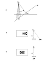
- two-viewpoint images can be acquired from a plurality of cameras, and three-dimensional reconstruction can be performed by stereo matching.
- An image conversion processing method for camera stereo matching will be described later.
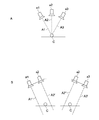
- each optical axis may be parallelized by a combination of a2 and a combination of cameras a2 and a3. That is, the optical axes A1 and A2, the optical axes A2 and A3 are made parallel, and images converted into the optical axes A1 ′ and A2 ′ and the optical axes A2 ′′ and A3 ′ are generated.
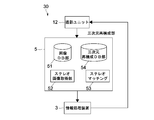
- the three-dimensional reconstruction unit 5 first acquires a combination of two viewpoints from cell images (N sheets) taken from a plurality of viewpoints (S201).
- the three-dimensional reconstruction unit 5 creates a stereo image in which the optical axes are parallelized (S202), creates a stereo matching image (S203), and stores the created three-dimensional image in the three-dimensional image DB unit 54 ( S204). If there are two different viewpoint combined images, the same operation is repeated (S205). In all combinations, a three-dimensional image of a cell can be obtained by stereo matching.
- the three-dimensional image created as described above is referred to in the information processing apparatus 3 for detection of a change in cell state. According to this embodiment, it is possible to accurately detect cell state changes such as surface irregularities and volume changes that could not be detected only by a difference value between two-dimensional images.
- the observation system 40 includes a photographing unit 42 and an information processing device 43.
- the photographing unit 42 has a thermal image photographing unit 201
- the information processing apparatus 43 is different from the first embodiment described above in that it has a thermal image analyzing unit 301.
- the photographing unit 2 may be composed of a single camera as in the first embodiment, or may be composed of a single camera or a plurality of cameras capable of acquiring multi-viewpoint images as in the second embodiment. May be. Further, the observation system 40 of the present embodiment may also include the three-dimensional reconstruction unit 5 described in the third embodiment.
- FIG. 17 is a flowchart showing a typical operation example of the observation system 40 of the present embodiment.
- the thermal image capturing unit in the present embodiment does not require a light source, it can capture non-invasively the cells. For this reason, it is suitable for always acquiring a cell image.
- the optical image is a three-dimensional image obtained from a plurality of optical images taken from multiple viewpoints
- the control unit detects a change in a state of a cell according to a change in a feature amount of the cell quantified based on information of the three-dimensional image.
- the information processing apparatus according to any one of (1) to (3) above,
- the cell is a fertilized egg
- the characteristic amount of the cell is a volume, surface area, sphericity, surface irregularity, and uniformity of cleavage of a fertilized egg.
Landscapes
- Engineering & Computer Science (AREA)
- Chemical & Material Sciences (AREA)
- Health & Medical Sciences (AREA)
- Life Sciences & Earth Sciences (AREA)
- Bioinformatics & Cheminformatics (AREA)
- Organic Chemistry (AREA)
- Wood Science & Technology (AREA)
- Zoology (AREA)
- General Health & Medical Sciences (AREA)
- Genetics & Genomics (AREA)
- Biochemistry (AREA)
- Analytical Chemistry (AREA)
- General Physics & Mathematics (AREA)
- Physics & Mathematics (AREA)
- Microbiology (AREA)
- General Engineering & Computer Science (AREA)
- Sustainable Development (AREA)
- Biotechnology (AREA)
- Biomedical Technology (AREA)
- Theoretical Computer Science (AREA)
- Molecular Biology (AREA)
- Immunology (AREA)
- Pathology (AREA)
- Computer Hardware Design (AREA)
- Signal Processing (AREA)
- Multimedia (AREA)
- Medical Informatics (AREA)
- Nuclear Medicine, Radiotherapy & Molecular Imaging (AREA)
- Radiology & Medical Imaging (AREA)
- Quality & Reliability (AREA)
- Computer Vision & Pattern Recognition (AREA)
- Human Computer Interaction (AREA)
- Spectroscopy & Molecular Physics (AREA)
- Apparatus Associated With Microorganisms And Enzymes (AREA)
- Investigating Or Analysing Materials By Optical Means (AREA)
Abstract
Description
上記制御部は、第1の撮影間隔で撮影した培養中の細胞の光学画像に基づいて細胞の状態変化の有無を検出し、上記状態変化を検出したとき、撮影モードを上記第1の撮影間隔から上記第1の撮影間隔よりも短い第2の撮影間隔に切り替える。
これにより、細胞へのダメージを軽減しつつ、より精度よく撮影間隔の切り替えができる。
これより、より精度よく撮影間隔の切り替えができ、重要な撮影タイミングの撮り逃しを防止することができる。
上記細胞培養容器は、細胞を培養する。
上記撮影部は、第1の撮影間隔で培養中の細胞の光学画像を取得する光学画像撮影部を有する。
上記制御部は、第1の撮影間隔で撮影した培養中の細胞の画像から細胞の状態変化の有無を検出し、上記状態変化を検出したとき、撮影モードを上記第1の撮影間隔から上記第1の撮影間隔よりも短い第2の撮影間隔に切り替える。
上記観察システムは、光学画像データベース部と、三次元再構成部と、をさらに具備してもよい。
上記光学画像データベース部は、上記多視点光学画像を保存する。
上記三次元再構成部は、上記光学画像データベース部より上記多視点光学画像を取得し、三次元再構成する。
なお、ここに記載された効果は必ずしも限定されるものではなく、本開示中に記載されたいずれかの効果であってもよい。
[観察システム概要]
図1は、本発明の一実施形態の観察システム10を示すブロック図である。図2は、観察システム10の主要部分を示すブロック図である。
続いて、情報処理装置3の詳細について説明する。情報処理装置3は、撮影間隔制御部31と、送受信部32と、メモリ33とを有する。
以下、図3に示すように、本実施形態の観察システム10の動作例を説明する。
本実施形態に係る撮影間隔制御部31の具体的な動作の一例について説明する。
細胞の状態変化は、培養される細胞の種類、細胞の発育段階などに応じて、異なる度合いで進行する。従前の通り、一定の間隔で細胞を撮影した場合、細胞の状態変化の著しい細胞分裂期では、細胞の評価にかかわる分裂の様子を撮り逃す恐れがある。一方で、細かい撮影間隔で撮影した場合、画像のデータ量が膨大となり、その処理にも膨大な時間がかかる。これに対して、本実施形態によれば、細胞の状態変化に応じて、撮影間隔を切り替えることができ、細胞が状態変化する重要なタイミングにおいて高密度で撮影することができる。また、重要なタイミングの時にのみ、高密度で撮影し、通常の撮影モードでは低密度で撮影することで、保存や処理すべき画像容量を抑えることができる。さらに、必要以上に撮影回数を増やさないことで、撮影時に照射される照射光による細胞へのダメージを軽減することができる。
続いて、本技術の第2の実施形態について説明する。以下、第1の実施形態と異なる構成について、主に説明し、第1の実施形態と同様の構成については同様の符号を付し、その説明を省略又は簡略化する。
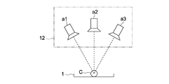
図5に示す観察システム20は、シャーレ等の平皿からなる培養容器1に収容された細胞Cを複数のカメラa1~a3で撮影する撮影ユニット12を有する。カメラa1~a3は、細胞Cを中心として細胞C表面に沿って周方向に配置されてもよい。これより、細胞の上半球を観察可能な多視点画像を取得でき、より精度よく細胞の状態変化を検出できる。後述するように、多視点画像から三次元再構成し、三次元画像を形成してもよい。配置するカメラの台数は特に限定されないが、カメラの台数が多いほど、オクルージョン領域の画像を補完でき、状態変化をより精度よく検出できる。
図6に示す観察システム20は、シャーレ等の平皿からなる培養容器1に収容された細胞Cを移動可能なカメラb1で撮影する撮影ユニット12を有する。カメラb1は、細胞Cを中心として、細胞C表面に沿って周方向に、カメラb1'の位置へと移動できるように構成される。これより、上記と同様に、細胞Cの上半球の多視点画像を取得することができる。さらに、配置されるカメラの台数を削減できるため、装置のコンパクト化、低コスト化も図れる。
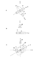
図7Aに示す観察システム20においては、細胞Cを収容する容器が透光性を有する円管等からなる円筒状容器11で構成されるとともにカメラd1が円筒状容器の側面の全周方向P1から細胞Cを観察可能なように、移動可能に構成される。これより、細胞Cの上半球画像だけでなく、下半球画像も取得することができる。即ち細胞Cの全周画像を取得することができるため、より精度よく細胞の状態変化を検出できる。
一方、図7Bに示す観察システムにおいては、円筒状容器11が周方向(Z軸周り)に回転可能に構成されるとともに、円筒状容器11の側面を撮影するカメラd2がZ軸と直交するY軸上の所定位置に固定される。これより、構成例2と同様に細胞Cの全周画像を取得することができる。また、カメラの台数の削減ができ、カメラを移動させるスペースも要しないため、装置のコンパクト化、低コスト化が図れる。
さらに、上記構成例(構成例3')に加えて、図7Cに示す観察システムにおいては、円筒状容器11のZ軸方向から細胞Cを撮影可能なように、カメラd3(d3')が移動可能に設置される。例えば、図示するようにX-Z平面(Y-Z平面)にて、細胞Cを中心にカメラd3(d3')が円運動する。これより、全方位からの光学画像を取得することが可能となるため、より精度よく細胞の状態変化を検出でき、重要なタイミングにおいて短い撮影間隔で撮影できる。
図8A、Bに示す観察システム20は、水平面(X-Y面)上に配置された細胞Cを囲むように等角度間隔で配置された鏡(M1~M3)を有する。そして、図8Bに示すように、細胞Cの鉛直方向上部に配置されたカメラe1が細胞Cと鏡(M1~M3)の反射像を撮影してもよい。これより、細胞Cの上部鉛直方向からの光学画像と、水平面内の細胞Cを中心とした円周方向からの光学画像を取得することができる。また、後述するように、多視点画像から三次元再構成し、三次元画像を形成してもよい。配置する鏡の台数は特に限定されないが、鏡の台数が多いほど、オクルージョン領域の画像を補完でき、状態変化をより精度よく検出できる。
図9に示す観察システムは、複数の細胞C1~C3を収容する培養容器12と、各細胞の鉛直方向上部にそれぞれ配置された複数のカメラf1~f3とを有し、各カメラf1~f3は、直下の細胞だけでなく、その周辺の細胞をも同時撮影することが可能な視野角を有する。その結果、例えば細胞C2に関しては、カメラf2(視点F2)からの視点画像だけでなく、カメラf1(視点F12)からの視点画像と、カメラf3(視点F32)からの視点画像とを取得することができる。これより、各細胞C1~C3について多視点からの観察が可能となる。さらに、配置するカメラの台数も削減することができる。
細胞の細胞分裂による状態変化は、撮影する角度によっては、分裂の境界面などを撮影できない場合がある。また、一視点からの撮影の場合、細胞の回転運動などの動的変化により今まで撮影できていた部位が撮影できない事態が生じる。本実施形態の構成では、多視点から細胞の光学画像を取得することで、細胞の状態変化をより見逃すことなく、検出することができる。このため、細胞の発育過程における重要なタイミングで撮影間隔の切り替えをより精度よく実現できる。
続いて、本技術の第3の実施形態について説明する。図12は、本実施形態に係る観察システム30の構成を示すブロック図である以下、第1、第2の実施形態と異なる構成について主に説明し、第1、第2の実施形態と同様の構成については同様の符号を付し、その説明を省略又は簡略化する。
情報処理装置3は、三次元再構成DB部54に保存された画像から、現在の細胞画像と過去の細胞画像のそれぞれ特徴を定量化し、定量化された特徴量の変化量に基づいて細胞の状態変化の有無を判定する。例えば、細胞が受精卵である場合、受精卵の体積、表面積、真球度、表面凹凸度、卵割の均一度などを定量化して、その変化分を状態変化の検出の有無に反映させてもよい。また、受精卵の種々の特徴点の動きから、三次元空間での細胞の回転や移動などの時間変化の動きについても、追従することができる。これより、細胞の状態変化を精度よく検出でき、受精卵の変化に合わせて適応的に撮影間隔を切り替えることができる。
続いて、本技術の第4の実施形態について説明する。以下、第1の実施形態と異なる構成について、主に説明し、第1の実施形態と同様の構成については同様の符号を付し、その説明を省略又は簡略化する。
光学撮影手段で常時細胞の状態変化を撮影した場合、細胞に常時光を照射する必要があり、細胞に多大なダメージを及ぼすこととなる。本実施形態によれば、細胞の状態変化の検出のためのツールとして、光学的撮影手段に代わって熱画像撮影手段を採用することで、細胞に与えるダメージを最小限にとどめながら、常時状態変化を観察できる。即ち、光学的撮影手段が細胞を撮影しない撮影間隔時においても、細胞の状態変化を検出できるので、細胞の評価にかかわる重要な撮影タイミングにおいて、撮影のタイムラグの少ない光学画像を取得することができる。
(1)第1の撮影間隔で撮影した培養中の細胞の光学画像に基づいて細胞の状態変化の有無を検出し、前記状態変化を検出したとき、撮影モードを前記第1の撮影間隔から前記第1の撮影間隔よりも短い第2の撮影間隔に切り替える制御部
を具備する情報処理装置。
(2)上記(1)に記載の情報処理装置であって、
前記制御部は、培養中の細胞の熱画像から細胞の状態変化の有無を検出する
情報処理装置。
(3)上記(1)又は(2)に記載の情報処理装置であって、
前記光学画像は、多視点から撮影された複数の光学画像から得られる三次元画像であって、
前記制御部は、前記三次元画像の情報に基づいて定量化された細胞の特徴量の変化に応じて、細胞の状態変化を検出する
情報処理装置。
(4)上記(1)~(3)のいずれか1つに記載の情報処理装置であって、
前記細胞は、受精卵であって、
前記細胞の特徴量は、受精卵の体積、表面積、真球度、表面凹凸度、及び卵割の均一度である
情報処理装置。
(5) 細胞を培養する細胞培養容器と、
第1の撮影間隔で培養中の細胞の光学画像を取得する光学画像撮影部を有する撮影部と
第1の撮影間隔で撮影した培養中の細胞の画像から細胞の状態変化の有無を検出し、前記状態変化を検出したとき、撮影モードを前記第1の撮影間隔から前記第1の撮影間隔よりも短い第2の撮影間隔に切り替える制御部と、
を具備する観察システム。
(6)上記(5)に記載の観察システムであって、
前記撮影部は、培養中の細胞の熱画像を連続的に取得する熱画像撮影部を有し、
前記制御部は、前記熱画像撮影部が撮影した前記熱画像に基づいて、細胞の状態変化の有無を検出する
観察システム。
(7)上記(5)又は(6)に記載の観察システムであって、
前記光学画像撮影部は、前記細胞の多視点光学画像を取得し、
前記観察システムは、前記多視点光学画像を保存する光学画像データベース部と、前記光学画像データベース部より前記多視点光学画像を取得し、三次元再構成する三次元再構成部と、をさらに具備する
観察システム。
(8)上記(7)に記載の観察システムであって、
前記制御部は、三次元再構成された前記多視点光学画像に基づいて、細胞の状態変化を検出する
観察システム。
観察システム。
(9)第1の撮影間隔で撮影した培養中の細胞の光学画像に基づいて細胞の状態変化の有無を検出し、
前記状態変化を検出したとき、撮影モードを前記第1の撮影間隔から前記第1の撮影間隔よりも短い第2の撮影間隔に切り替える
観察方法。
(10)情報処理装置に、
第1の撮影間隔で撮影した培養中の細胞の光学画像に基づいて細胞の状態変化の有無を検出するステップと、
前記状態変化を検出したとき、撮影モードを前記第1の撮影間隔から前記第1の撮影間隔よりも短い第2の撮影間隔に切り替えるステップと
を実行させるプログラム。
2,12,42…撮影ユニット
3,43…情報処理装置
4,51…画像DB部
5…三次元再構成部
10,20,30,40…観察システム
11…円筒状容器
14…解析部
15…更新部
31…撮影間隔制御部
32…送受信部
33…メモリ
34…解析部
30,40…観察システム
52…ステレオ画像取得部
53…ステレオマッチング部
54…三次元再構成DB部
201…熱画像撮影部
301…熱画像解析部
a1~a3,b1,d1~d3,f1~f3,g1~g2…カメラ
M1~M3…鏡
Claims (10)
- 第1の撮影間隔で撮影した培養中の細胞の光学画像に基づいて細胞の状態変化の有無を検出し、前記状態変化を検出したとき、撮影モードを前記第1の撮影間隔から前記第1の撮影間隔よりも短い第2の撮影間隔に切り替える制御部
を具備する情報処理装置。 - 請求項1に記載の情報処理装置であって、
前記制御部は、培養中の細胞の熱画像から細胞の状態変化の有無を検出する
情報処理装置。 - 請求項1に記載の情報処理装置であって、
前記光学画像は、多視点から撮影された複数の光学画像から得られる三次元画像であり、
前記制御部は、前記三次元画像の情報に基づいて定量化された細胞の特徴量の変化に応じて、細胞の状態変化を検出する
情報処理装置。 - 請求項1に記載の情報処理装置であって、
前記細胞は、受精卵であって、
前記細胞の特徴量は、受精卵の体積、表面積、真球度、表面凹凸度、及び卵割の均一度である
情報処理装置。 - 細胞を培養する細胞培養容器と、
第1の撮影間隔で培養中の細胞の光学画像を取得する光学画像撮影部を有する撮影部と
第1の撮影間隔で撮影した培養中の細胞の画像から細胞の状態変化の有無を検出し、前記状態変化を検出したとき、撮影モードを前記第1の撮影間隔から前記第1の撮影間隔よりも短い第2の撮影間隔に切り替える制御部と、
を具備する観察システム。 - 請求項5に記載の観察システムであって、
前記撮影部は、培養中の細胞の熱画像を連続的に取得する熱画像撮影部を有し、
前記制御部は、前記熱画像撮影部が撮影した前記熱画像に基づいて、細胞の状態変化の有無を検出する
観察システム。 - 請求項5に記載の観察システムであって、
前記光学画像撮影部は、前記細胞の多視点光学画像を取得し、
前記観察システムは、前記多視点光学画像を保存する光学画像データベース部と、前記光学画像データベース部より前記多視点光学画像を取得し、三次元再構成する三次元再構成部と、をさらに具備する
観察システム。 - 請求項7に記載の観察システムであって、
前記制御部は、三次元再構成された前記多視点光学画像に基づいて、細胞の状態変化を検出する
観察システム。 - 第1の撮影間隔で撮影した培養中の細胞の光学画像に基づいて細胞の状態変化の有無を検出し、
前記状態変化を検出したとき、撮影モードを前記第1の撮影間隔から前記第1の撮影間隔よりも短い第2の撮影間隔に切り替える
観察方法。 - 情報処理装置に、
第1の撮影間隔で撮影した培養中の細胞の光学画像に基づいて細胞の状態変化の有無を検出するステップと、
前記状態変化を検出したとき、撮影モードを前記第1の撮影間隔から前記第1の撮影間隔よりも短い第2の撮影間隔に切り替えるステップと
を実行させるプログラム。
Priority Applications (6)
| Application Number | Priority Date | Filing Date | Title |
|---|---|---|---|
| AU2017283878A AU2017283878A1 (en) | 2016-06-15 | 2017-05-18 | Information processing device, observation system, observation method, and program |
| EP17813083.7A EP3473998A4 (en) | 2016-06-15 | 2017-05-18 | INFORMATION PROCESSING DEVICE, OBSERVATION SYSTEM, OBSERVATION PROCEDURE AND PROGRAM |
| CA3026225A CA3026225A1 (en) | 2016-06-15 | 2017-05-18 | Information processing apparatus, observation system, observation method, and program |
| JP2018523603A JP6992748B2 (ja) | 2016-06-15 | 2017-05-18 | 情報処理装置、観察システム、観察方法及びプログラム |
| US16/307,662 US10872414B2 (en) | 2016-06-15 | 2017-05-18 | Information processing apparatus, observation system, observation method, and program |
| BR112018075406A BR112018075406A2 (pt) | 2016-06-15 | 2017-05-18 | aparelho de processamento de informação, sistema de observação, método de observação, e, programa. |
Applications Claiming Priority (2)
| Application Number | Priority Date | Filing Date | Title |
|---|---|---|---|
| JP2016-119214 | 2016-06-15 | ||
| JP2016119214 | 2016-06-15 |
Publications (1)
| Publication Number | Publication Date |
|---|---|
| WO2017217180A1 true WO2017217180A1 (ja) | 2017-12-21 |
Family
ID=60663456
Family Applications (1)
| Application Number | Title | Priority Date | Filing Date |
|---|---|---|---|
| PCT/JP2017/018654 Ceased WO2017217180A1 (ja) | 2016-06-15 | 2017-05-18 | 情報処理装置、観察システム、観察方法及びプログラム |
Country Status (7)
| Country | Link |
|---|---|
| US (1) | US10872414B2 (ja) |
| EP (1) | EP3473998A4 (ja) |
| JP (1) | JP6992748B2 (ja) |
| AU (1) | AU2017283878A1 (ja) |
| BR (1) | BR112018075406A2 (ja) |
| CA (1) | CA3026225A1 (ja) |
| WO (1) | WO2017217180A1 (ja) |
Cited By (3)
| Publication number | Priority date | Publication date | Assignee | Title |
|---|---|---|---|---|
| WO2019235563A1 (ja) * | 2018-06-08 | 2019-12-12 | オリンパス株式会社 | 観察装置 |
| JP2020076743A (ja) * | 2018-09-18 | 2020-05-21 | カール・ツアイス・メディテック・アーゲー | 対象物の特性を判断するための方法及び装置 |
| WO2021182153A1 (ja) * | 2020-03-09 | 2021-09-16 | ソニーグループ株式会社 | 情報処理装置、情報処理システム、情報処理方法およびプログラム |
Families Citing this family (2)
| Publication number | Priority date | Publication date | Assignee | Title |
|---|---|---|---|---|
| EP3550009A4 (en) | 2016-11-29 | 2019-12-18 | Sony Corporation | INFORMATION PROCESSING DEVICE, INFORMATION PROCESSING PROCESS, PROGRAM AND OBSERVATION SYSTEM |
| JP2022096324A (ja) * | 2020-12-17 | 2022-06-29 | オリンパス株式会社 | 細胞回収装置、細胞回収方法、プログラム |
Citations (4)
| Publication number | Priority date | Publication date | Assignee | Title |
|---|---|---|---|---|
| JP2011017620A (ja) * | 2009-07-09 | 2011-01-27 | Nikon Corp | 形状測定方法、画像処理プログラム及び観察装置 |
| JP2012095627A (ja) * | 2010-11-05 | 2012-05-24 | Nikon Corp | 細胞培養装置およびプログラム |
| JP2013502233A (ja) * | 2009-08-22 | 2013-01-24 | ザ ボード オブ トラスティーズ オブ ザ リーランド スタンフォード ジュニア ユニバーシティ | 胚、卵母細胞、および幹細胞の撮像および評価 |
| JP2015223174A (ja) * | 2014-05-30 | 2015-12-14 | 富士フイルム株式会社 | 細胞判定装置および方法並びにプログラム |
Family Cites Families (12)
| Publication number | Priority date | Publication date | Assignee | Title |
|---|---|---|---|---|
| US5989835A (en) * | 1997-02-27 | 1999-11-23 | Cellomics, Inc. | System for cell-based screening |
| JP4128791B2 (ja) * | 2002-03-27 | 2008-07-30 | 株式会社堀内 | 有精卵の雌雄鑑別技術 |
| PL378577A1 (pl) * | 2003-03-24 | 2006-05-02 | Sterix Limited | Pochodne estrogenu jako inhibitory sulfatazy steroidowej |
| JPWO2009031283A1 (ja) * | 2007-09-03 | 2010-12-09 | 株式会社ニコン | 培養装置、培養情報管理方法およびプログラム |
| US8515143B2 (en) | 2009-01-09 | 2013-08-20 | Dai Nippon Printing Co., Ltd. | Embryo quality evaluation assistance system, embryo quality evaluation assistance apparatus and embryo quality evaluation assistance method |
| DK2726865T3 (en) * | 2011-07-01 | 2017-03-20 | Cambridge Entpr Ltd | Methods for predicting viability of mammalian embryos |
| DK2893341T3 (en) * | 2012-09-04 | 2018-06-25 | Univ Leuven Kath | METHOD AND APPARATUS FOR INVESTIGATING EGGS |
| JP6097952B2 (ja) * | 2013-08-22 | 2017-03-22 | 富士フイルム株式会社 | 観察画像判定装置および方法並びにプログラム |
| JP6173950B2 (ja) * | 2014-03-04 | 2017-08-02 | 富士フイルム株式会社 | 細胞撮像制御装置および方法並びにプログラム |
| JP6325858B2 (ja) * | 2014-03-20 | 2018-05-16 | 株式会社Screenホールディングス | 薬効評価方法および画像処理装置 |
| ES2837840T3 (es) * | 2014-03-20 | 2021-07-01 | Ares Trading Sa | Medida cuantitativa de la cinética de desarrollo de la morfología de mórula y blastocisto humanos |
| US20190331905A1 (en) * | 2016-07-01 | 2019-10-31 | Sony Corporation | Image acquisition method, image acquisition apparatus, program, and culture vessel |
-
2017
- 2017-05-18 JP JP2018523603A patent/JP6992748B2/ja active Active
- 2017-05-18 US US16/307,662 patent/US10872414B2/en active Active
- 2017-05-18 BR BR112018075406A patent/BR112018075406A2/pt not_active Application Discontinuation
- 2017-05-18 AU AU2017283878A patent/AU2017283878A1/en not_active Abandoned
- 2017-05-18 CA CA3026225A patent/CA3026225A1/en active Pending
- 2017-05-18 EP EP17813083.7A patent/EP3473998A4/en not_active Withdrawn
- 2017-05-18 WO PCT/JP2017/018654 patent/WO2017217180A1/ja not_active Ceased
Patent Citations (4)
| Publication number | Priority date | Publication date | Assignee | Title |
|---|---|---|---|---|
| JP2011017620A (ja) * | 2009-07-09 | 2011-01-27 | Nikon Corp | 形状測定方法、画像処理プログラム及び観察装置 |
| JP2013502233A (ja) * | 2009-08-22 | 2013-01-24 | ザ ボード オブ トラスティーズ オブ ザ リーランド スタンフォード ジュニア ユニバーシティ | 胚、卵母細胞、および幹細胞の撮像および評価 |
| JP2012095627A (ja) * | 2010-11-05 | 2012-05-24 | Nikon Corp | 細胞培養装置およびプログラム |
| JP2015223174A (ja) * | 2014-05-30 | 2015-12-14 | 富士フイルム株式会社 | 細胞判定装置および方法並びにプログラム |
Non-Patent Citations (1)
| Title |
|---|
| See also references of EP3473998A4 * |
Cited By (8)
| Publication number | Priority date | Publication date | Assignee | Title |
|---|---|---|---|---|
| WO2019235563A1 (ja) * | 2018-06-08 | 2019-12-12 | オリンパス株式会社 | 観察装置 |
| WO2019234916A1 (ja) * | 2018-06-08 | 2019-12-12 | オリンパス株式会社 | 観察装置 |
| JPWO2019235563A1 (ja) * | 2018-06-08 | 2021-06-17 | オリンパス株式会社 | 観察装置および細胞観察方法 |
| JP7064584B2 (ja) | 2018-06-08 | 2022-05-10 | オリンパス株式会社 | 観察装置および細胞観察方法 |
| US11635364B2 (en) | 2018-06-08 | 2023-04-25 | Evident Corporation | Observation device |
| JP2020076743A (ja) * | 2018-09-18 | 2020-05-21 | カール・ツアイス・メディテック・アーゲー | 対象物の特性を判断するための方法及び装置 |
| US11391937B2 (en) | 2018-09-18 | 2022-07-19 | Carl Zeiss Meditec Ag | Method and device for determining a property of an object |
| WO2021182153A1 (ja) * | 2020-03-09 | 2021-09-16 | ソニーグループ株式会社 | 情報処理装置、情報処理システム、情報処理方法およびプログラム |
Also Published As
| Publication number | Publication date |
|---|---|
| JP6992748B2 (ja) | 2022-02-03 |
| AU2017283878A1 (en) | 2019-01-03 |
| EP3473998A1 (en) | 2019-04-24 |
| CA3026225A1 (en) | 2017-12-21 |
| JPWO2017217180A1 (ja) | 2019-04-11 |
| US20190220979A1 (en) | 2019-07-18 |
| EP3473998A4 (en) | 2019-07-03 |
| BR112018075406A2 (pt) | 2019-03-19 |
| US10872414B2 (en) | 2020-12-22 |
Similar Documents
| Publication | Publication Date | Title |
|---|---|---|
| JP6992748B2 (ja) | 情報処理装置、観察システム、観察方法及びプログラム | |
| US20150109424A1 (en) | Desktop three-dimensional scanner for dental use provided with two-axis motion unit in which camera and projector are coupled to unit for changing horizontal axis of rotation of stage | |
| WO2020069221A1 (en) | Camera array for a mediated-reality system | |
| US10921577B2 (en) | Endoscope device | |
| CA3079243C (en) | Image reconstruction method, device and microscopic imaging device | |
| CN103654699B (zh) | 一种激发荧光双目内窥系统的成像方法 | |
| CN105158893B (zh) | 基于lcd液晶面板的可编程孔径显微镜系统的光场成像方法 | |
| CN110012196A (zh) | 一种光场相机重聚焦方法 | |
| CN113267141B (zh) | 一种显微三维信息采集设备 | |
| JPWO2019065260A1 (ja) | 情報処理装置、情報処理方法、及び、プログラム、並びに、交換レンズ | |
| WO2018042786A1 (ja) | 画像処理方法、画像処理装置、および撮像装置 | |
| CN108387517A (zh) | 切片扫描方法及系统 | |
| US20160063307A1 (en) | Image acquisition device and control method therefor | |
| CN106772974A (zh) | 快速三维折射率显微成像的系统和方法 | |
| CN202145259U (zh) | 一种双镜头单图像传感器的双目立体视觉成像装置 | |
| CN109726853A (zh) | 基于机器视觉的工业协作机器人路径规划算法 | |
| US11422349B2 (en) | Dual processor image processing | |
| CN108133469A (zh) | 基于epi的光场拼接装置及方法 | |
| CN102911852B (zh) | 克隆菌株自动筛选装置及方法 | |
| KR101275127B1 (ko) | 초점 가변 액체 렌즈를 이용한 3차원 이미지 촬영장치 및 방법 | |
| TW201723635A (zh) | 將光學獲取系統所擷取影像編碼之裝置及方法 | |
| JP6640610B2 (ja) | 観察装置、測定システム及び観察方法 | |
| JP2023553792A (ja) | 撮像システム、腹腔鏡及び対象物を撮像するための方法 | |
| US12249102B2 (en) | Methods and systems for obtaining and processing images | |
| CN103927757B (zh) | 基于分级采样的目标物体立体视觉三维分析处理方法 |
Legal Events
| Date | Code | Title | Description |
|---|---|---|---|
| ENP | Entry into the national phase |
Ref document number: 2018523603 Country of ref document: JP Kind code of ref document: A |
|
| 121 | Ep: the epo has been informed by wipo that ep was designated in this application |
Ref document number: 17813083 Country of ref document: EP Kind code of ref document: A1 |
|
| ENP | Entry into the national phase |
Ref document number: 3026225 Country of ref document: CA |
|
| NENP | Non-entry into the national phase |
Ref country code: DE |
|
| REG | Reference to national code |
Ref country code: BR Ref legal event code: B01A Ref document number: 112018075406 Country of ref document: BR |
|
| ENP | Entry into the national phase |
Ref document number: 2017283878 Country of ref document: AU Date of ref document: 20170518 Kind code of ref document: A |
|
| ENP | Entry into the national phase |
Ref document number: 2017813083 Country of ref document: EP Effective date: 20190115 |
|
| ENP | Entry into the national phase |
Ref document number: 112018075406 Country of ref document: BR Kind code of ref document: A2 Effective date: 20181207 |
|
| WWW | Wipo information: withdrawn in national office |
Ref document number: 2017813083 Country of ref document: EP |