WO2017221400A1 - 冷凍サイクル装置およびそれに用いられる室外熱交換器 - Google Patents
冷凍サイクル装置およびそれに用いられる室外熱交換器 Download PDFInfo
- Publication number
- WO2017221400A1 WO2017221400A1 PCT/JP2016/068810 JP2016068810W WO2017221400A1 WO 2017221400 A1 WO2017221400 A1 WO 2017221400A1 JP 2016068810 W JP2016068810 W JP 2016068810W WO 2017221400 A1 WO2017221400 A1 WO 2017221400A1
- Authority
- WO
- WIPO (PCT)
- Prior art keywords
- heat exchanger
- heat transfer
- transfer tube
- refrigerant
- heat exchange
- Prior art date
- Legal status (The legal status is an assumption and is not a legal conclusion. Google has not performed a legal analysis and makes no representation as to the accuracy of the status listed.)
- Ceased
Links
Images









Classifications
-
- F—MECHANICAL ENGINEERING; LIGHTING; HEATING; WEAPONS; BLASTING
- F25—REFRIGERATION OR COOLING; COMBINED HEATING AND REFRIGERATION SYSTEMS; HEAT PUMP SYSTEMS; MANUFACTURE OR STORAGE OF ICE; LIQUEFACTION SOLIDIFICATION OF GASES
- F25B—REFRIGERATION MACHINES, PLANTS OR SYSTEMS; COMBINED HEATING AND REFRIGERATION SYSTEMS; HEAT PUMP SYSTEMS
- F25B39/00—Evaporators; Condensers
- F25B39/02—Evaporators
- F25B39/028—Evaporators having distributing means
-
- F—MECHANICAL ENGINEERING; LIGHTING; HEATING; WEAPONS; BLASTING
- F25—REFRIGERATION OR COOLING; COMBINED HEATING AND REFRIGERATION SYSTEMS; HEAT PUMP SYSTEMS; MANUFACTURE OR STORAGE OF ICE; LIQUEFACTION SOLIDIFICATION OF GASES
- F25B—REFRIGERATION MACHINES, PLANTS OR SYSTEMS; COMBINED HEATING AND REFRIGERATION SYSTEMS; HEAT PUMP SYSTEMS
- F25B13/00—Compression machines, plants or systems, with reversible cycle
-
- F—MECHANICAL ENGINEERING; LIGHTING; HEATING; WEAPONS; BLASTING
- F25—REFRIGERATION OR COOLING; COMBINED HEATING AND REFRIGERATION SYSTEMS; HEAT PUMP SYSTEMS; MANUFACTURE OR STORAGE OF ICE; LIQUEFACTION SOLIDIFICATION OF GASES
- F25B—REFRIGERATION MACHINES, PLANTS OR SYSTEMS; COMBINED HEATING AND REFRIGERATION SYSTEMS; HEAT PUMP SYSTEMS
- F25B39/00—Evaporators; Condensers
-
- F—MECHANICAL ENGINEERING; LIGHTING; HEATING; WEAPONS; BLASTING
- F25—REFRIGERATION OR COOLING; COMBINED HEATING AND REFRIGERATION SYSTEMS; HEAT PUMP SYSTEMS; MANUFACTURE OR STORAGE OF ICE; LIQUEFACTION SOLIDIFICATION OF GASES
- F25B—REFRIGERATION MACHINES, PLANTS OR SYSTEMS; COMBINED HEATING AND REFRIGERATION SYSTEMS; HEAT PUMP SYSTEMS
- F25B39/00—Evaporators; Condensers
- F25B39/02—Evaporators
-
- F—MECHANICAL ENGINEERING; LIGHTING; HEATING; WEAPONS; BLASTING
- F25—REFRIGERATION OR COOLING; COMBINED HEATING AND REFRIGERATION SYSTEMS; HEAT PUMP SYSTEMS; MANUFACTURE OR STORAGE OF ICE; LIQUEFACTION SOLIDIFICATION OF GASES
- F25B—REFRIGERATION MACHINES, PLANTS OR SYSTEMS; COMBINED HEATING AND REFRIGERATION SYSTEMS; HEAT PUMP SYSTEMS
- F25B47/00—Arrangements for preventing or removing deposits or corrosion, not provided for in another subclass
- F25B47/006—Arrangements for preventing or removing deposits or corrosion, not provided for in another subclass for preventing frost
-
- F—MECHANICAL ENGINEERING; LIGHTING; HEATING; WEAPONS; BLASTING
- F25—REFRIGERATION OR COOLING; COMBINED HEATING AND REFRIGERATION SYSTEMS; HEAT PUMP SYSTEMS; MANUFACTURE OR STORAGE OF ICE; LIQUEFACTION SOLIDIFICATION OF GASES
- F25B—REFRIGERATION MACHINES, PLANTS OR SYSTEMS; COMBINED HEATING AND REFRIGERATION SYSTEMS; HEAT PUMP SYSTEMS
- F25B47/00—Arrangements for preventing or removing deposits or corrosion, not provided for in another subclass
- F25B47/02—Defrosting cycles
-
- F—MECHANICAL ENGINEERING; LIGHTING; HEATING; WEAPONS; BLASTING
- F25—REFRIGERATION OR COOLING; COMBINED HEATING AND REFRIGERATION SYSTEMS; HEAT PUMP SYSTEMS; MANUFACTURE OR STORAGE OF ICE; LIQUEFACTION SOLIDIFICATION OF GASES
- F25B—REFRIGERATION MACHINES, PLANTS OR SYSTEMS; COMBINED HEATING AND REFRIGERATION SYSTEMS; HEAT PUMP SYSTEMS
- F25B47/00—Arrangements for preventing or removing deposits or corrosion, not provided for in another subclass
- F25B47/02—Defrosting cycles
- F25B47/022—Defrosting cycles hot gas defrosting
- F25B47/025—Defrosting cycles hot gas defrosting by reversing the cycle
-
- F—MECHANICAL ENGINEERING; LIGHTING; HEATING; WEAPONS; BLASTING
- F28—HEAT EXCHANGE IN GENERAL
- F28F—DETAILS OF HEAT-EXCHANGE AND HEAT-TRANSFER APPARATUS, OF GENERAL APPLICATION
- F28F17/00—Removing ice or water from heat-exchange apparatus
-
- F—MECHANICAL ENGINEERING; LIGHTING; HEATING; WEAPONS; BLASTING
- F28—HEAT EXCHANGE IN GENERAL
- F28F—DETAILS OF HEAT-EXCHANGE AND HEAT-TRANSFER APPARATUS, OF GENERAL APPLICATION
- F28F9/00—Casings; Header boxes; Auxiliary supports for elements; Auxiliary members within casings
- F28F9/02—Header boxes; End plates
- F28F9/026—Header boxes; End plates with static flow control means, e.g. with means for uniformly distributing heat exchange media into conduits
- F28F9/027—Header boxes; End plates with static flow control means, e.g. with means for uniformly distributing heat exchange media into conduits in the form of distribution pipes
- F28F9/0275—Header boxes; End plates with static flow control means, e.g. with means for uniformly distributing heat exchange media into conduits in the form of distribution pipes with multiple branch pipes
Definitions
- the present invention relates to a refrigeration cycle apparatus and an outdoor heat exchanger used therefor, and in particular, a refrigeration cycle apparatus including an outdoor heat exchanger having a main heat exchange part and an auxiliary heat exchange part, and such an outdoor heat exchanger, It is about.
- An outdoor heat exchanger used in an air conditioner as an example of a refrigeration cycle apparatus includes an outdoor heat exchanger in which a heat transfer tube through which a refrigerant flows is arranged so as to penetrate a plurality of plate-like fins.
- Such an outdoor heat exchanger is called a fin-and-tube heat exchanger.
- a flat tube having a flat cross-sectional shape with a flat cross-sectional shape is used as a heat transfer tube so that heat exchange is efficiently performed.
- the air conditioner equipped with the outdoor heat exchanger described above has the following problems.
- the outdoor heat exchanger is operated as an evaporator.
- the temperature of the outdoor air where the outdoor heat exchanger is installed approaches below freezing point, in order to maintain heat exchange performance, the surface temperature of the outdoor heat exchanger falls below below freezing point, and frost adheres to the outdoor heat exchanger.
- frost adheres to the outdoor heat exchanger.
- frost may also adhere to the auxiliary heat exchange unit.
- frost adheres to the outdoor heat exchanger the ventilation resistance increases and the heat exchange performance is degraded.
- a defrosting operation is performed in the air conditioner.
- the present invention has been made to solve the above-described problems, and one object thereof is to provide a refrigeration cycle apparatus including an outdoor heat exchanger that prevents frost from adhering to an auxiliary heat exchange section. Another object is to provide an outdoor heat exchanger provided with such an auxiliary heat exchange unit.
- the refrigeration cycle apparatus is a refrigeration cycle apparatus provided with an outdoor heat exchanger.
- the outdoor heat exchanger includes a first heat exchange part and a second heat exchange part arranged alongside the first heat exchange part.
- the first heat exchange unit includes a plurality of plate-shaped fins, a first heat transfer tube, a second heat transfer tube, and a pressure loss mechanism.
- the first heat transfer tube is disposed so as to penetrate the plurality of fins.
- the second heat transfer tube is arranged so as to penetrate the plurality of fins in such a manner that the second heat transfer tube is spaced apart in a direction intersecting the direction in which the first heat transfer tube extends.
- the pressure loss mechanism lowers the pressure of the refrigerant flowing through the first heat exchange unit.
- the outdoor heat exchanger operates as an evaporator and the temperature of the refrigerant flowing out from the first heat exchange unit is lower than the freezing point of water, the temperature of the refrigerant flowing into the first heat exchange unit is the outside air temperature. And the temperature of the refrigerant flowing out from the first heat exchanging portion is operated to be lower than the outside air temperature.
- the outdoor heat exchanger according to the present invention is an outdoor heat exchanger including a first heat exchange part and a second heat exchange part arranged side by side with the first heat exchange part.
- the first heat exchange unit includes a plurality of plate-shaped fins, a first heat transfer tube, a second heat transfer tube, and a pressure loss unit.
- the first heat transfer tube is disposed so as to penetrate the plurality of fins.
- the second heat transfer tube is arranged so as to penetrate the plurality of fins in such a manner that the second heat transfer tube is spaced apart in a direction intersecting the direction in which the first heat transfer tube extends.
- the pressure loss part is interposed between the first heat transfer tube and the second heat transfer tube.
- the temperature of the refrigerant flowing out from the first heat exchange unit is lower than the freezing point of water.
- the operation is performed such that the temperature of the refrigerant flowing into the first heat exchange unit is higher than the outside air temperature, and the temperature of the refrigerant flowing out from the first heat exchange unit is lower than the outside air temperature.
- the pressure loss portion for reducing the pressure of the refrigerant is provided between the first heat transfer tube and the second heat transfer tube arranged so as to penetrate the plurality of fins, respectively. Yes.
- frost adheres to the first heat exchange part of the outdoor heat exchanger by controlling the temperature of the refrigerant in relation to the temperature of the air. Can be prevented.
- FIG. 1 shows an example of the refrigerant circuit of the air conditioning apparatus which concerns on embodiment.
- it is a perspective view which shows an outdoor heat exchanger.
- it is sectional drawing which shows an example of the refrigerant path of a heat exchanger tube.
- it is sectional drawing which shows the other example of the refrigerant path of a heat exchanger tube.
- FIG. 1 it is a perspective view showing the flow of the refrigerant in the outdoor heat exchanger when the outdoor heat exchanger is operated to operate as a condenser.
- FIG. 1 it is a perspective view showing the flow of the refrigerant in the outdoor heat exchanger when the outdoor heat exchanger is operated to operate as an evaporator.
- the air conditioner according to the first comparative example the relationship between the temperature of the refrigerant flowing through the auxiliary heat exchanger in the outdoor heat exchanger and the temperature of the air when the outdoor heat exchanger is operated as an evaporator It is a figure for demonstrating.
- FIG. It is a figure which shows the flow of the refrigerant
- the relationship between the temperature of the refrigerant and the temperature of the air flowing through the auxiliary heat exchanger in the outdoor heat exchanger when the outdoor heat exchanger is operated as an evaporator It is a figure for demonstrating.
- the outdoor heat exchanger flows through the auxiliary heat exchange unit in the outdoor heat exchanger when operated as an evaporator. It is a figure for demonstrating the relationship between the temperature of a refrigerant
- FIG. 17 is a cross sectional view taken along a cross sectional line XVII-XVII shown in FIG. 16 in the embodiment.
- FIG. 17 is a cross sectional view taken along a cross sectional line XVIII-XVIII shown in FIG. 16 in the embodiment.
- FIG. 17 is a cross sectional view taken along a cross sectional line XIX-XIX shown in FIG. 16 in the embodiment.
- FIG. 1 it is a perspective view showing typically an auxiliary heat exchange part which attached a header as the 4th example of a pressure loss part.
- FIG. 1 it is a perspective view showing typically an auxiliary heat exchange part which attached a U-shaped tube as the 5th example of a pressure loss part.
- Embodiment 1 An overall configuration (refrigerant circuit) of an air conditioner as an example of a refrigeration cycle apparatus will be described.
- the air conditioner 1 includes a compressor 3, an indoor heat exchanger 5, an indoor fan 7, an expansion device 9, an outdoor heat exchanger 11, an outdoor fan 21, a four-way valve 23, and a control unit 51. ing.
- the compressor 3, the indoor heat exchanger 5, the expansion device 9, the outdoor heat exchanger 11, and the four-way valve 23 are connected by refrigerant piping.
- the air conditioner 1 is also provided with two temperature sensors 53 and 55 for detecting the temperature of the refrigerant in the outdoor heat exchanger 11 and a temperature sensor 57 for detecting the temperature of the outside air.
- the temperature sensors 53, 55, and 57 are electrically connected to the control unit 51.
- the controller 51 causes the outside air (air) to prevent frost from adhering to the outdoor heat exchanger 11 when the outdoor heat exchanger 11 operates as an evaporator.
- the temperature of the refrigerant is managed in relation to the temperature of the refrigerant.
- the outdoor heat exchanger 11 includes a main heat exchange unit 13 and an auxiliary heat exchange unit 15.
- a main heat exchange unit 13 is disposed on the auxiliary heat exchange unit 15.
- a plurality of first heat transfer tubes 33 a and a plurality of second heat transfer tubes 33 b are disposed so as to penetrate the plurality of plate-shaped fins 31 that are spaced apart from each other.
- FIG. 3 shows a flat tube in which one refrigerant passage 35 is formed.
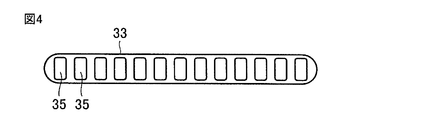
- FIG. 4 shows a flat tube in which a plurality of refrigerant passages 35 are formed.
- cross-sectional shape may be circular or an elliptical heat exchanger tube.
- Each of the plurality of first heat transfer tubes 33a is disposed at a distance from each other in the minor axis direction.
- the plurality of first heat transfer tubes 33a are arranged in the first row.
- the first row is the auxiliary heat exchange unit 15a.
- Each of the plurality of second heat transfer tubes 33b is disposed at a distance from each other in the minor axis direction.
- the plurality of second heat transfer tubes 33b are arranged in the second row.
- the second row is the auxiliary heat exchange unit 15b.
- One end (first end) of each of the plurality of first heat transfer tubes 33a is connected to the distributor 25.
- the distributor 25 of the auxiliary heat exchange unit 15 is connected to the expansion device 9 (see FIG. 5).
- a temperature sensor 53 that detects the temperature of the refrigerant is provided in a refrigerant pipe portion in the vicinity of the distributor 25.
- the other end (second end) of each of the plurality of first heat transfer tubes 33a and the other end (third end) of each of the plurality of second heat transfer tubes 33b are pressure loss portions that cause the refrigerant pressure to be lost. 17 (pressure loss mechanism). The specific structure of the pressure loss part 17 will be described later.
- a temperature sensor 55 that detects the temperature of the refrigerant is provided at a portion of the refrigerant pipe 37 that is connected to one end of the second heat transfer pipe 33b.
- FIG. 2 shows a case where the temperature sensor 55 is typically provided in the refrigerant pipe connected to one end of the second heat transfer pipe 33b arranged at the bottom.
- a temperature sensor may be provided at each refrigerant pipe connected to one end of the heat pipe 33b.
- a plurality of third heat transfer tubes 33c and a plurality of fourth heat transfer tubes 33d are arranged so as to penetrate the plurality of plate-like fins 31 arranged at intervals.
- the third heat transfer tube 33c and the fourth heat transfer tube 33d flat tubes are used similarly to the first heat transfer tube 33a and the second heat transfer tube 33b.
- FIG. 2 for simplification of the drawing, a third heat transfer tube 33c and a fourth heat transfer tube 33d are shown.
- Each of the plurality of third heat transfer tubes 33c is arranged at a distance from each other in the minor axis direction.
- the plurality of third heat transfer tubes 33c are arranged in the first row (windward row).
- the first row is the main heat exchange unit 13a.
- Each of the plurality of fourth heat transfer tubes 33d is disposed at a distance from each other in the minor axis direction.
- the plurality of fourth heat transfer tubes 33d are arranged in the second row (leeward row).
- the second row is the main heat exchange unit 13b.
- each of the plurality of fourth heat transfer tubes 33d is connected to one end of each of the plurality of second heat transfer tubes 33b via the distributor 29.
- Each other end of the plurality of fourth heat transfer tubes 33d is connected to the corresponding other end of the plurality of third heat transfer tubes 33c.
- One end of each of the plurality of third heat transfer tubes 33 c is connected to the header 27.
- the header 27 is connected to the four-way valve 23 (see FIG. 5).
- the outdoor heat exchanger 11 of the air conditioner 1 is configured as described above.
- a high-temperature and high-pressure gaseous refrigerant is discharged from the compressor 3.
- the refrigerant flows according to dotted arrows.
- the discharged high-temperature and high-pressure gas refrigerant flows into the outdoor heat exchanger 11 through the four-way valve 23.
- the outdoor heat exchanger 11 heat exchange is performed between the refrigerant flowing in and the air supplied by the outdoor fan 21, and the high-temperature and high-pressure gas refrigerant is condensed to a high-pressure liquid refrigerant (single phase).
- the high-pressure liquid refrigerant sent out from the outdoor heat exchanger 11 becomes a two-phase refrigerant of low-pressure gas refrigerant and liquid refrigerant by the expansion device 9.
- the two-phase refrigerant flows into the indoor heat exchanger 5.
- heat exchange is performed between the refrigerant in the two-phase state that has flowed in and the air supplied by the indoor fan 7, and the refrigerant in the two-phase state evaporates as the liquid refrigerant evaporates.
- the low-pressure gas refrigerant sent out from the indoor heat exchanger 5 flows into the compressor 3 via the four-way valve 23, is compressed to become a high-temperature and high-pressure gas refrigerant, and is discharged from the compressor 3 again. Thereafter, this cycle is repeated.
- the flow of the refrigerant in the outdoor heat exchanger 11 when the outdoor heat exchanger 11 is operated to operate as a condenser will be described.
- the refrigerant first flows through the main heat exchange unit 13 and then flows through the auxiliary heat exchange unit 15.
- the outdoor fan 21 causes the air to flow from the auxiliary heat exchange unit 15a and the main heat exchange unit 13a in the first row (windward row) to the second row (leeward row).
- the auxiliary heat exchanging portion 15b and the main heat exchanging portion 13b To the auxiliary heat exchanging portion 15b and the main heat exchanging portion 13b.
- the refrigerant sent from the compressor 3 flows into the header 27, passes through the header 27, and flows in the direction indicated by the arrow through the third heat transfer tube 33c of the main heat exchange section 13a.
- the refrigerant that has flowed through the third heat transfer tube 33c then flows through the fourth heat transfer tube 33d of the main heat exchange section 13b in the direction indicated by the arrow and flows into the distributor 29.
- the refrigerant that has flowed into the distributor 29 then flows in the direction indicated by the arrow through the second heat transfer tube 33b of the auxiliary heat exchange unit 15b.
- the refrigerant that has flowed through the second heat transfer tube 33b then flows in the direction indicated by the arrow through the first heat transfer tube 33a of the auxiliary heat exchange unit 15a.
- the refrigerant that has flowed through the first heat transfer tube 33 a is sent out of the outdoor heat exchanger 11.
- the discharged high-temperature and high-pressure gas refrigerant flows into the indoor heat exchanger 5 through the four-way valve 23.
- the indoor heat exchanger 5 heat exchange is performed between the flowing gas refrigerant and the air supplied by the indoor fan 7, and the high-temperature and high-pressure gas refrigerant is condensed to a high-pressure liquid refrigerant (single phase). become.
- the high-pressure liquid refrigerant sent out from the indoor heat exchanger 5 becomes a two-phase refrigerant consisting of a low-pressure gas refrigerant and a liquid refrigerant by the expansion device 9.
- the refrigerant in the two-phase state flows into the outdoor heat exchanger 11.
- the outdoor heat exchanger 11 heat exchange is performed between the refrigerant flowing in the two-phase state and the air supplied by the outdoor fan 21, and the refrigerant in the two-phase state evaporates as the liquid refrigerant evaporates.
- the low-pressure gas refrigerant sent out from the outdoor heat exchanger 11 flows into the compressor 3 through the four-way valve 23, is compressed to become a high-temperature and high-pressure gas refrigerant, and is discharged from the compressor 3 again. Thereafter, this cycle is repeated.
- the flow of the refrigerant in the outdoor heat exchanger 11 when the outdoor heat exchanger 11 operates to operate as an evaporator will be described.
- the refrigerant first flows through the auxiliary heat exchange unit 15, and then flows through the main heat exchange unit 13.
- the outdoor fan 21 (see FIG. 1) allows air to flow from the auxiliary heat exchanging portion 15a and the main heat exchanging portion 13a in the first row (windward row) to the second row (leeward row). ) To the auxiliary heat exchanging portion 15b and the main heat exchanging portion 13b.
- the refrigerant sent from the expansion device 9 flows into the distributor 25 of the auxiliary heat exchanging section 15, and flows through the distributor 25 in the direction indicated by the arrow through the first heat transfer tube 33a of the auxiliary heat exchanging section 15a.
- the refrigerant that has flowed through the first heat transfer tube 33a then flows in the direction indicated by the arrow through the second heat transfer tube 33b of the auxiliary heat exchange unit 15b.
- the refrigerant that has flowed through the second heat transfer tube 33b then flows into the distributor 29 of the main heat exchange unit 13.
- the refrigerant that has flowed into the distributor 29 then flows in the direction indicated by the arrow through the fourth heat transfer tube 33d of the main heat exchange unit 13b.
- the refrigerant that has flowed through the fourth heat transfer tube 33d then flows through the third heat transfer tube 33c of the main heat exchange section 13a in the direction indicated by the arrow.
- the refrigerant that has flowed through the third heat transfer pipe 33 c flows into the header 27, passes through the header 27, and is sent out of the outdoor heat exchanger 11.
- the temperature of the refrigerant flowing into the auxiliary heat exchanger 15 (refrigerant inlet temperature), the temperature of the refrigerant sent from the auxiliary heat exchanger 15 (refrigerant outlet temperature), and the temperature of the outside air Is detected, and by operating the air conditioner 1 so that the temperature of the refrigerant has a predetermined temperature relationship with the temperature of the outside air, it is possible to prevent frost from adhering to the auxiliary heat exchange unit 15. . This will be described.
- the air dry bulb temperature is 5 ° C. and the air wet bulb temperature is 4 ° C.
- the dew point temperature of the air is about 2.8 ° C.
- the air dry bulb temperature falls below the dew point temperature due to heat exchange with the refrigerant, the moisture in the air condenses and forms water droplets in the outdoor heat exchanger. Adhere to.
- the air that tries to pass through the outdoor heat exchanger flows to the leeward side of the outdoor heat exchanger at a temperature lower than the dew point temperature.
- the air dry bulb temperature and the dew point temperature may be close to the refrigerant temperature. Then, when the dew point temperature is below the freezing point of water (for example, 0 ° C.), frost may adhere to the outdoor heat exchanger.
- the air dry bulb temperature is 2 ° C.
- the air wet bulb temperature is 1 ° C.
- the dew point temperature is ⁇ 0.4 ° C.
- FIG. 8 is a graph (broken line) showing the transition of the temperature of the refrigerant flowing through the auxiliary heat exchange unit 15 with respect to the refrigerant flow direction, a graph (solid line) showing the transition of the air dry bulb temperature with respect to the air flow direction, and the air flow.
- the graph (dotted line) which shows transition of the dew point temperature with respect to a direction is shown.
- This operating condition is a condition in which the refrigerant inlet temperature (Tref-in) flowing into the auxiliary heat exchanger 15 is lower than the outside air temperature (air inlet temperature (Tair-in)).
- the air dry bulb temperature immediately becomes almost the same as the dew point temperature. Since the dew point temperature is lower than the freezing point of water (for example, 0 ° C.), frost adheres to most of the outdoor heat exchanger 11 including the auxiliary heat exchanger 15.
- the water (drain water) in which the frost has melted flows toward the lower part of the outdoor heat exchanger 11 by gravity, and the outdoor heat exchange. It will be discharged from the vessel 11.
- the speed at which the drain water flows down decreases, and the drain water flows from above to the auxiliary heat exchange unit 15 disposed under the main heat exchange unit 13. The state of flowing down continues. For this reason, an extra amount of heat may be required for defrosting the auxiliary heat exchange unit 15. Moreover, time may be required for the defrosting operation.
- the defrosting operation is generally the same operation mode as the operation in which the outdoor heat exchanger operates as a condenser, and the direction in which the refrigerant flows is during the operation in which the outdoor heat exchanger 11 operates as an evaporator.
- the refrigerant flows in a direction opposite to the direction of the refrigerant, and the refrigerant flows through the auxiliary heat exchange unit 15 after flowing through the main heat exchange unit 13 (see FIG. 6).
- the auxiliary heat exchange unit 15 is disposed below the main heat exchange unit 13.
- the amount of heat of the refrigerant is lost in the main heat exchange section 13 on the upstream side of the refrigerant flow, and in the auxiliary heat exchange section 15 on the downstream side, the defrosting ability of the attached frost is reduced, and the defrost time is reduced. May become longer. As a result, it may be impossible to maintain a comfortable state, for example, the indoor temperature gradually decreases.
- the defrosting operation is finished in a state where frost remains and the operation in which the outdoor heat exchanger 11 operates as an evaporator is resumed, the frost further grows, and the auxiliary heat exchange unit 15 and the like are installed.
- the heat transfer tube may be damaged and develop into a serious problem such that the refrigerant leaks.
- FIG. 9 is a graph (broken line) showing the transition of the temperature of the refrigerant flowing through the auxiliary heat exchanger 15 with respect to the flow direction of the refrigerant, a graph (solid line) showing the transition of the air dry bulb temperature with respect to the flow direction of air, and the air flow.
- the graph (dotted line) which shows transition of the dew point temperature with respect to a direction is shown.
- This operating condition is a condition in which the refrigerant outlet temperature (Tref-out) sent from the auxiliary heat exchanger 15 is higher than the outside air temperature (air inlet temperature (Tair-in)).
- Ton-out refrigerant outlet temperature
- Air-in air inlet temperature
- FIG. 10 is a graph (broken line) showing the transition of the temperature of the refrigerant flowing through the auxiliary heat exchanger 15 with respect to the refrigerant flow direction, a graph (solid line) showing the transition of the air dry bulb temperature with respect to the air flow direction, and the air flow.
- the graph (dotted line) which shows transition of the dew point temperature with respect to a direction is shown.
- the operation in which the outdoor heat exchanger 11 operates as an evaporator is performed when the refrigerant outlet temperature (Tref-out) is lower than the freezing point of water (for example, 0 ° C.), the refrigerant inlet temperature flowing into the auxiliary heat exchanger 15 ( Tref-in) is higher than the outside air temperature (air inlet temperature (Tair-in)), and the refrigerant outlet temperature (Tref-out) sent from the auxiliary heat exchanging section 15 is outside air temperature (air inlet temperature (Tair-in)). )) Lower conditions.
- adjusting the refrigerant pressure loss in the auxiliary heat exchange unit 15 is the same as adjusting the refrigerant temperature. Means that.
- this auxiliary heat exchanging part 15 by providing a pressure loss part 17 between the auxiliary heat exchanging part 15a located in the first row and the auxiliary heat exchanging part 15b located in the second row, the auxiliary heat exchanging part 15a is made to function as a condenser, and the auxiliary heat exchange part 15b is made to function as an evaporator.
- the auxiliary heat exchange unit 15a located in the windward row By causing the auxiliary heat exchange unit 15a located in the windward row to function as a condenser, the temperature of the air rises, and even if the auxiliary heat exchange unit 15b located in the leeward row functions as an evaporator, The temperature is less likely to fall below the dew point temperature. Thereby, as the whole auxiliary heat exchanging part 15, the temperature of the refrigerant can be lowered to function as an evaporator, and frost can be prevented from adhering to the auxiliary heat exchanging part 15.
- the refrigerant outlet temperature (Tref-out) sent from the auxiliary heat exchange unit 15 may be operated to be higher than the dew point temperature. .
- the refrigerant flows through the auxiliary heat exchange unit 15a located on the windward side, and then the auxiliary heat exchange unit 15b located on the leeward side.
- Flowing That is, the refrigerant flows from the windward side to the leeward side in the same manner as the air flow, and such a refrigerant flow is called a parallel flow.
- an opposing flow When the refrigerant flows from the leeward side to the leeward side with respect to the parallel flow, it is called an opposing flow.
- the outdoor heat exchanger 11 performs an operation to operate as an evaporator
- a description will be given of a case where a refrigerant is caused to flow in an opposing flow to the auxiliary heat exchange unit 15 of the outdoor heat exchanger 11 ( Third comparative example).
- the refrigerant first flows through the auxiliary heat exchange unit 15, and then flows through the main heat exchange unit 13.
- the second heat transfer tube 33b of the auxiliary heat exchange unit 15b flows in the direction indicated by the arrow.
- the refrigerant that has flowed through the second heat transfer tube 33b then flows through the first heat transfer tube 33a of the auxiliary heat exchanger 15a in the direction indicated by the arrow.
- the refrigerant that has flowed through the auxiliary heat exchanging portion 15a is sent out from the outdoor heat exchanger 11 after flowing through the main heat exchanging portion 13, as in the case shown in FIG.
- FIG. 12 is a graph (broken line) showing the transition of the refrigerant temperature flowing through the auxiliary heat exchange unit 15 with respect to the refrigerant flow direction when the refrigerant flow is a counter flow, and the transition of the air dry bulb temperature with respect to the air flow direction.
- the graph (solid line) to show, and the graph (dotted line) which show transition of dew point temperature with respect to the flow direction of air are shown.
- the temperature of the refrigerant flowing through the auxiliary heat exchange unit 15a located on the leeward side flows through the auxiliary heat exchange unit 15b located on the leeward side. It will be lower than the temperature.
- frost may adhere to the auxiliary heat exchange unit 15a.
- the refrigerant flowing through the auxiliary heat exchange unit 15a located on the leeward side is higher than the outside air temperature (air inlet temperature (Tair-in)
- the refrigerant flowing through the auxiliary heat exchange unit 15b located on the leeward side Is also higher than the outside air temperature (air inlet temperature (Tair-in)).
- the whole auxiliary heat exchange part 15 will function as a condenser, and as it demonstrated about FIG. 9, heat exchange property will fall. Therefore, in order to perform an operation in which the outdoor heat exchanger 11 operates as an evaporator so that frost does not adhere to the auxiliary heat exchange unit 15, the refrigerant flow should be parallel flow along the air flow. It is desirable to drive.
- FIG. 13 is a graph (broken line) showing a transition of the temperature of the refrigerant flowing through the auxiliary heat exchanger 15 with respect to the refrigerant flow direction during operation in which the outdoor heat exchanger 11 operates as an evaporator, and an air dry bulb with respect to the air flow direction.
- the graph (solid line) which shows transition of temperature, and the graph (dotted line) which shows transition of dew point temperature with respect to the flow direction of air are shown.
- the temperature of the refrigerant gradually decreases due to friction loss in the heat transfer tubes.
- the friction loss in the heat transfer tube is determined by the flow rate of the refrigerant, the shape of the heat transfer tube, and the length of the heat transfer tube.
- the circulation amount of the refrigerant in the air conditioner, the dimensions of the heat transfer tubes in the outdoor heat exchanger, the number of passes of the heat transfer tubes, etc. are set to predetermined values based on the design, respectively, and the temperature of the refrigerant is set to the predetermined temperature.
- the refrigerant inlet temperature (Tref-in) is higher than the outside air temperature (air inlet temperature (Tair-in)).
- frost can be prevented from adhering to the auxiliary heat exchanging section 15. Can do.
- the refrigerant outlet temperature (Tref-out) sent from the auxiliary heat exchange unit 15 to be higher than the dew point temperature, it is possible to reliably prevent frost from adhering to the auxiliary heat exchange unit 15. Can do.
- a throttling device may be used as the pressure loss unit 17 interposed between the auxiliary heat exchange unit 15a and the auxiliary heat exchange unit 15b.
- the first heat transfer tubes 33 a are compared to the plurality of first heat transfer tubes 33 a disposed in the auxiliary heat exchange portion 15 a and the plurality of second heat transfer tubes 33 b disposed in the auxiliary heat exchange portion 15 b.
- the expansion device 39 provided for each one path (path) from the first to the second heat transfer tube 33b is shown.
- the refrigerant flowing through each of the plurality of first heat transfer tubes 33a is merged on the upstream side of the expansion device and branched (distributed) again on the downstream side of the expansion device, so that the plurality of second heat transfer tubes 33b
- throttle device 39 provided in the aspect sent out to each is shown.
- the auxiliary heat exchanging unit 15 can adjust the temperature of the refrigerant on the downstream side of the expansion device 39 by adjusting the opening of the expansion device 39 with respect to the temperature of the refrigerant on the upstream side of the expansion device 39. That is, by installing the expansion device 39 between the auxiliary heat exchange unit 15a and the auxiliary heat exchange unit 15b (between rows), the temperature of the refrigerant flowing through the auxiliary heat exchange unit 15a located on the windward side and the leeward side The temperature of the refrigerant flowing through the auxiliary heat exchanger 15b that is positioned can be adjusted separately.
- all the auxiliary heat exchanging portions 15a located on the windward side can function as a condenser, and all the auxiliary heat exchanging portions 15b located on the leeward side can function as an evaporator.
- a header (inter-column header) may be used as the pressure loss unit 17 interposed between the auxiliary heat exchange unit 15a and the auxiliary heat exchange unit 15b.
- FIG. 16 shows the inter-column header 41 arranged between the auxiliary heat exchange unit 15a and the auxiliary heat exchange unit 15b.
- the inter-column header 41 is provided with a flow path through which the refrigerant flows for each path from the first heat transfer tube 33 a to the second heat transfer tube 33 b. It has been.
- a throttle portion 43 is formed in which the cross-sectional area of the flow path is narrower than the cross-sectional areas of other flow paths.
- the pressure loss can be adjusted before and after the inter-row header 41, the temperature of the refrigerant flowing through the auxiliary heat exchange portion 15a, The temperature of the refrigerant flowing through the auxiliary heat exchange unit 15b can be adjusted separately.
- the auxiliary heat exchanger 15a can function as a condenser and the auxiliary heat exchanger 15b can function as an evaporator, and the outdoor heat exchanger 11 can be operated during the operation in which the outdoor heat exchanger 11 operates as an evaporator. It is possible to prevent frost from adhering to the auxiliary heat exchanger 15.
- auxiliary heat exchange part 15a As the pressure loss part 17 interposed between the auxiliary heat exchange part 15a and the auxiliary heat exchange part 15b, for example, two headers of a header connected to the auxiliary heat exchange part 15a and a header connected to the auxiliary heat exchange part 15b are provided. It may be used.
- FIG. 20 shows a header including a header 45a, a header 45b, and a header connection pipe 47.
- the header 45a is connected to the first heat transfer tube 33a of the auxiliary heat exchange unit 15a.
- the header 45b is connected to the second heat transfer tube 33b of the auxiliary heat exchange unit 15b.
- the header connection pipe 47 connects the header 45a and the header 45b.
- the header connecting pipe 47 is used as the throttle portion 43 and the inner diameter thereof is adjusted to divide the temperature of the refrigerant flowing through the auxiliary heat exchanging portion 15a and the temperature of the refrigerant flowing through the auxiliary heat exchanging portion 15b.
- the outdoor heat exchanger 11 operates as an evaporator, it is possible to prevent frost from adhering to the auxiliary heat exchanging portion 15 of the outdoor heat exchanger 11. Further, even if a flow path causing friction loss is separately provided in the flow paths of the headers 45a and 45b and the pressure loss is adjusted by adjusting the shape of the flow path, the adhesion of frost is prevented. Can do.
- a U-shaped tube may be used as the pressure loss unit 17 interposed between the auxiliary heat exchange unit 15a and the auxiliary heat exchange unit 15b.
- a U-shaped tube 49 is connected to each path from the first heat transfer tube 33a to the second heat transfer tube 33b.
- the temperature of the refrigerant flowing through the auxiliary heat exchanging portion 15a and the temperature of the refrigerant flowing through the auxiliary heat exchanging portion 15b can be adjusted separately, so that outdoor heat exchange can be performed. It is possible to prevent frost from adhering to the auxiliary heat exchange part 15 of the outdoor heat exchanger 11 during the operation in which the vessel 11 operates as an evaporator.
- any refrigerant such as the refrigerant R410A, the refrigerant R407C, the refrigerant R32, the refrigerant R507A, the refrigerant HFO1234yf, or the like can be used to assist the outdoor heat exchanger 11. It is possible to prevent frost from adhering to the heat exchange unit 15.
- Refrigerant R410A and refrigerant R407C are mixed refrigerants, and are particularly called non-azeotropic mixed refrigerants.
- Non-azeotropic refrigerant mixtures differ in composition between the gas phase and the liquid phase in the state of wet steam, and evaporate or vaporize while changing the composition and changing the temperature in two phases of gas refrigerant and liquid refrigerant under a constant pressure. It has the property of causing a phase change of condensation.
- the refrigerant R407C and the like have a very small temperature change during the phase change, and are particularly called pseudo-azeotropic refrigerants.
- Refrigerant R32 and refrigerant HFO1234yf are single component refrigerants.
- the refrigerant R507A is a mixed refrigerant and is called an azeotropic mixed refrigerant.
- An azeotrope refrigerant has the same composition of the vapor and liquid phases of wet steam at a certain component ratio, and, like a single component refrigerant, the phase change of evaporation or condensation remains constant at a constant pressure. It has the property of occurring.
- the refrigerant outlet temperature is lower than the freezing point of water (for example, 0 ° C.).
- frost is prevented from adhering to the auxiliary heat exchanging portion 15 of the outdoor heat exchanger 11. be able to.
- refrigerating machine oil used in the air conditioner a refrigerating machine oil having compatibility is used in consideration of mutual solubility with the applied refrigerant.
- fluorocarbon refrigerants such as refrigerant R410A use alkylbenzene oil-based, ester oil-based or ether oil-based refrigerator oil.
- refrigerating machine oil such as mineral oil or fluorine oil may be used.
- an air conditioner has been described as an example of the refrigeration cycle apparatus.
- the refrigeration cycle apparatus is not limited to an air conditioner, and can be applied to an apparatus in which an outdoor heat exchanger such as a heat pump water heater exchanges heat with air.
- an outdoor heat exchanger such as a heat pump water heater exchanges heat with air.
- the refrigerating-cycle apparatus provided with the outdoor heat exchanger demonstrated in embodiment it is possible to combine variously as needed.
- the present invention is effectively used for a refrigeration cycle apparatus such as an air conditioner having an outdoor heat exchanger having a main heat exchange part and an auxiliary heat exchange part.
Landscapes
- Engineering & Computer Science (AREA)
- Physics & Mathematics (AREA)
- Mechanical Engineering (AREA)
- Thermal Sciences (AREA)
- General Engineering & Computer Science (AREA)
- Other Air-Conditioning Systems (AREA)
- Air-Conditioning For Vehicles (AREA)
- Details Of Heat-Exchange And Heat-Transfer (AREA)
- Heat-Exchange Devices With Radiators And Conduit Assemblies (AREA)
- Compression-Type Refrigeration Machines With Reversible Cycles (AREA)
Abstract
空気調和装置(1)の室外熱交換器(11)は、主熱交換部(13)および補助熱交換部(15)を備えている。室外熱交換器(11)を蒸発器として作動する運転をさせる際には、室外熱交換器(11)では、冷媒は、補助熱交換部(15)から主熱交換部(13)へ流れ、補助熱交換部(15)では、補助熱交換部(15a)の第1伝熱管(33a)から、補助熱交換部(15b)の第2伝熱管(33b)へ流れる。冷媒出口温度が水の凝固点よりも低い場合において、補助熱交換部(15)に流れ込む冷媒入り口温度が、外気温度よりも高く、かつ、補助熱交換部(15)から送り出される冷媒出口温度が、外気温度よりも低くなるように運転される。
Description
本発明は、冷凍サイクル装置およびそれに用いられる室外熱交換器に関し、特に、主熱交換部および補助熱交換部を備えた室外熱交換器を含む冷凍サイクル装置と、そのような室外熱交換器とに関するものである。
冷凍サイクル装置の一例としての空気調和装置に使用されている室外熱交換器には、板状の複数のフィンを貫通するように、冷媒が流れる伝熱管を配置させた室外熱交換器がある。このような室外熱交換器は、フィンアンドチューブ型熱交換器と呼ばれている。この種の室外熱交換器には、熱交換が効率的に行われるように、伝熱管として、断面形状が扁平状の扁平型断面形状を有する扁平管が使用されている。
室外熱交換器には、凝縮用の主熱交換部と過冷却用の補助熱交換部とを備えたタイプがある。一般に、補助熱交換部の上に主熱交換部が配置されている。冷凍サイクル装置を冷房運転させる際には、室外熱交換器に流れ込んだ冷媒は、主熱交換部を流れる間に空気と熱交換が行われて凝縮し、液冷媒となる。その後、その液冷媒が補助熱交換部を流れることでさらに冷却されることになる。なお、この種の室外熱交換器を備えた冷凍サイクル装置を開示した特許文献の例として、特許文献1がある。
しかしながら、上述した室外熱交換器を備えた空気調和装置では、次のような問題点があった。空気調和装置を、暖房運転させる際には、室外熱交換器は蒸発器として運転される。室外熱交換器が設置されている外気の温度が氷点下に近づくと、熱交換性能を維持するために、室外熱交換器の表面温度が氷点下よりも下がり、室外熱交換器には霜が付着することがある。
特に、補助熱交換部も蒸発器として空気調和装置を運転させる場合には、その補助熱交換部にも霜が付着することがある。室外熱交換器に霜が付着すると、通風抵抗が増大して熱交換性能が低下してしまう。霜の付着を防止するために、空気調和装置では、除霜運転が行われる。
室外熱交換器に霜が付着した状態で除霜運転を行うと、溶けた水は、室外熱交換器の上部から下部を流れて、室外熱交換器の下方にドレン水として落ちていく。このとき、伝熱管として扁平管を用いた熱交換器では、溶けた水が下方へ落ちにくくなり、下方に位置する補助熱交換部には、水が溜まりやすくなる。
このため、付着した霜を溶かすために除霜運転を行う時間が長くなるなどして、消費電力が増えることになる。一方、霜または水が残った状態で暖房運転が再開されると、残った水が、冷媒によって冷やされて凍りついてしまい、室外熱交換器を損傷させてしまうおそれがある。
本発明は、上記問題点を解決するためになされたものであり、一つの目的は、補助熱交換部への霜の付着が防止される室外熱交換器を備えた冷凍サイクル装置を提供することであり、他の目的は、そのような補助熱交換部を備えた室外熱交換器を提供することである。
本発明に係る冷凍サイクル装置は、室外熱交換器を備えた冷凍サイクル装置である。室外熱交換器は、第1熱交換部と、その第1熱交換部と並んで配置された第2熱交換部とを含む。第1熱交換部は、板状の複数のフィンと第1伝熱管と第2伝熱管と圧力損失機構とを備えている。第1伝熱管は、複数のフィンを貫通するように配置されている。第2伝熱管は、第1伝熱管が延在する方向と交差する方向に距離を隔てられる態様で、複数のフィンを貫通するように配置されている。圧力損失機構は、第1熱交換部を流れる冷媒の圧力を下げる。室外熱交換器が蒸発器として作動する運転時に、第1熱交換部から流出する冷媒の温度が水の凝固点よりも低くなる場合には、第1熱交換部に流入する冷媒の温度が外気温度よりも高く、かつ、第1熱交換部から流出する冷媒の温度が外気温度よりも低くなるように運転する。
本発明に係る室外熱交換器は、第1熱交換部およびその第1熱交換部と並んで配置された第2熱交換部を含む室外熱交換器である。第1熱交換部は、板状の複数のフィンと第1伝熱管と第2伝熱管と圧力損失部とを備えている。第1伝熱管は、複数のフィンを貫通するように配置されている。第2伝熱管は、第1伝熱管が延在する方向と交差する方向に距離を隔てられる態様で、複数のフィンを貫通するように配置されている。圧力損失部は、第1伝熱管と第2伝熱管との間に介在する。
本発明に係る冷凍サイクル装置によれば、室外熱交換器が蒸発器として作動する運転を行う際に、第1熱交換部から流出する冷媒の温度が水の凝固点よりも低くなる場合に、第1熱交換部に流入する冷媒の温度が外気温度よりも高く、かつ、第1熱交換部から流出する冷媒の温度が外気温度よりも低くなるように運転する。これにより、室外熱交換器の第1熱交換部に霜が付着するのを防止することができる。
本発明に係る室外熱交換器によれば、複数のフィンをそれぞれ貫通するように配置された第1伝熱管と第2伝熱管との間に、冷媒の圧力を下げる圧力損失部が設けられている。これにより、室外熱交換器が蒸発器として作動する運転を行う際に、冷媒の温度を空気の温度との関係で制御することで、室外熱交換器の第1熱交換部に霜が付着するのを防止することができる。
実施の形態1.
はじめに、冷凍サイクル装置の一例としての空気調和装置の全体の構成(冷媒回路)について説明する。図1に示すように、空気調和装置1は、圧縮機3、室内熱交換器5、室内ファン7、絞り装置9、室外熱交換器11、室外ファン21、四方弁23および制御部51を備えている。圧縮機3、室内熱交換器5、絞り装置9、室外熱交換器11および四方弁23が、冷媒配管によって繋がっている。
はじめに、冷凍サイクル装置の一例としての空気調和装置の全体の構成(冷媒回路)について説明する。図1に示すように、空気調和装置1は、圧縮機3、室内熱交換器5、室内ファン7、絞り装置9、室外熱交換器11、室外ファン21、四方弁23および制御部51を備えている。圧縮機3、室内熱交換器5、絞り装置9、室外熱交換器11および四方弁23が、冷媒配管によって繋がっている。
また、空気調和装置1には、室外熱交換器11における冷媒の温度を検出する2つの温度センサ53、55と、外気の温度を検知する温度センサ57とが設けられている。温度センサ53、55、57は、制御部51に電気的に接続されている。後述するように、空気調和装置1では、制御部51は、室外熱交換器11が蒸発器として作動する運転をさせる際に、室外熱交換器11に霜が付着しないように、外気(空気)の温度との関係で冷媒の温度を管理する。
次に、その室外熱交換器11について説明する。図2に示すように、室外熱交換器11は、主熱交換部13および補助熱交換部15を備えている。補助熱交換部15の上に主熱交換部13が配置されている。補助熱交換部15では、互いに間隔を隔てて配置された板状の複数のフィン31を貫通するように、複数の第1伝熱管33aと複数の第2伝熱管33bとが配置されている。
第1伝熱管33aおよび第2伝熱管33bとして、長径と短径を有する扁平断面形状の扁平管が使用されている。その扁平管の一例として、図3に、一つの冷媒通路35が形成された扁平管を示す。扁平管の他の例として、図4に、複数の冷媒通路35が形成された扁平管を示す。なお、第1伝熱管および第2伝熱管としては、扁平管に限られず、たとえば、断面形状が円形または楕円形等の伝熱管であってもよい。
複数の第1伝熱管33aのそれぞれは、短径の方向に互いに距離を隔てて配置されている。複数の第1伝熱管33aは第1列目に配置されている。第1列目は、補助熱交換部15aとなる。複数の第2伝熱管33bのそれぞれは、短径の方向に互いに距離を隔てて配置されている。複数の第2伝熱管33bは、第2列目に配置されている。第2列目は、補助熱交換部15bとなる。後述するように、空気調和装置が動作する際には、補助熱交換部15a(風上列)は風上側に位置し、補助熱交換部15b(風下列)は風下側に位置することになる。
複数の第1伝熱管33aのそれぞれの一端(第1端部)は、分配器25に繋がっている。補助熱交換部15の分配器25は、絞り装置9(図5参照)に繋がっている。その分配器25の近傍の冷媒配管の部分に、冷媒の温度を検知する温度センサ53が設けられている。複数の第1伝熱管33aのそれぞれの他端(第2端部)と、複数の第2伝熱管33bのそれぞれの他端(第3端部)とは、冷媒の圧力を損失させる圧力損失部17(圧力損失機構)を介して繋がっている。圧力損失部17の具体的な構造については、後述する。
複数の第2伝熱管33bのそれぞれの一端(第4端部)は、主熱交換部13に繋がっている。第2伝熱管33bの一端に繋がっている冷媒配管37の部分に、冷媒の温度を検知する温度センサ55が設けられている。なお、図2では、代表的に、一番下に配置されている第2伝熱管33bの一端に繋がっている冷媒配管に温度センサ55が設けられている場合を示すが、複数の第2伝熱管33bの一端に繋がっているそれぞれの冷媒配管の部分に温度センサを設けてもよい。
主熱交換部13では、互いに間隔を隔てて配置された板状の複数のフィン31を貫通するように、複数の第3伝熱管33cと複数の第4伝熱管33dとが配置されている。第3伝熱管33cおよび第4伝熱管33dとして、第1伝熱管33aおよび第2伝熱管33bと同様に、扁平管が使用されている。なお、図2では、図面の簡略化のために、一系統の第3伝熱管33cと第4伝熱管33dとが示されている。
複数の第3伝熱管33cのそれぞれは、短径の方向に互いに距離を隔てて配置されている。複数の第3伝熱管33cは、第1列目(風上列)に配置されている。第1列目は、主熱交換部13aとなる。複数の第4伝熱管33dのそれぞれは、短径の方向に互いに距離を隔てて配置されている。複数の第4伝熱管33dは、第2列目(風下列)に配置されている。第2列目は、主熱交換部13bとなる。
複数の第4伝熱管33dのそれぞれの一端は、分配器29を介して、複数の第2伝熱管33bのそれぞれの一端と繋がっている。複数の第4伝熱管33dのそれぞれの他端は、複数の第3伝熱管33cのうちの対応する他端に繋がっている。複数の第3伝熱管33cのそれぞれの一端は、ヘッダ27に繋がっている。ヘッダ27は、四方弁23(図5参照)に繋がっている。空気調和装置1の室外熱交換器11は、上記のように構成される。
次に、上述した空気調和装置1の動作(冷媒の流れ)として、まず、室外熱交換器11が凝縮器として作動する運転(冷房運転)の場合について説明する。
図5に示すように、圧縮機3を駆動させることによって、圧縮機3から高温高圧のガス状態の冷媒が吐出する。以下、点線矢印にしたがって冷媒が流れる。吐出した高温高圧のガス冷媒(単相)は、四方弁23を介して室外熱交換器11に流れ込む。室外熱交換器11では、流れ込んだ冷媒と、室外ファン21によって供給される空気との間で熱交換が行われて、高温高圧のガス冷媒は、凝縮して高圧の液冷媒(単相)になる。
室外熱交換器11から送り出された高圧の液冷媒は、絞り装置9によって、低圧のガス冷媒と液冷媒との二相状態の冷媒になる。二相状態の冷媒は、室内熱交換器5に流れ込む。室内熱交換器5では、流れ込んだ二相状態の冷媒と、室内ファン7によって供給される空気との間で熱交換が行われて、二相状態の冷媒は、液冷媒が蒸発して低圧のガス冷媒(単相)になる。この熱交換によって、室内が冷却されることになる。室内熱交換器5から送り出された低圧のガス冷媒は、四方弁23を介して圧縮機3に流れ込み、圧縮されて高温高圧のガス冷媒となって、再び圧縮機3から吐出する。以下、このサイクルが繰り返される。
ここで、室外熱交換器11が凝縮器として作動する運転を行う場合の室外熱交換器11における冷媒の流れについて説明する。図6に示すように、室外熱交換器11では、冷媒は、まず、主熱交換部13を流れ、次に、補助熱交換部15を流れる。また、室外ファン21(図1参照)によって、空気は、矢印に示すように、第1列目(風上列)の補助熱交換部15aおよび主熱交換部13aから第2列目(風下列)の補助熱交換部15bおよび主熱交換部13bへ向かって流れる。
圧縮機3から送られた冷媒は、ヘッダ27に流れ込み、ヘッダ27を経て、主熱交換部13aの第3伝熱管33cを矢印に示す向きに流れる。第3伝熱管33cを流れた冷媒は、次に、主熱交換部13bの第4伝熱管33dを矢印に示す向きに流れて、分配器29に流れ込む。
分配器29に流れ込んだ冷媒は、次に、補助熱交換部15bの第2伝熱管33bを矢印に示す向きに流れる。第2伝熱管33bを流れた冷媒は、次に、補助熱交換部15aの第1伝熱管33aを矢印示す向きに流れる。第1伝熱管33aを流れた冷媒は、室外熱交換器11の外へ送り出される。
次に、室外熱交換器11が蒸発器として作動する運転(暖房運転)の場合について説明する。図5に示すように、圧縮機3を駆動させることによって、圧縮機3から高温高圧のガス状態の冷媒が吐出する。以下、実線矢印にしたがって冷媒が流れる。
吐出した高温高圧のガス冷媒(単相)は、四方弁23を介して室内熱交換器5に流れ込む。室内熱交換器5では、流れ込んだガス冷媒と、室内ファン7によって供給される空気との間で熱交換が行われて、高温高圧のガス冷媒は、凝縮して高圧の液冷媒(単相)になる。この熱交換によって、室内が暖房されることになる。室内熱交換器5から送り出された高圧の液冷媒は、絞り装置9によって、低圧のガス冷媒と液冷媒との二相状態の冷媒になる。
二相状態の冷媒は、室外熱交換器11に流れ込む。室外熱交換器11では、流れ込んだ二相状態の冷媒と、室外ファン21によって供給される空気との間で熱交換が行われて、二相状態の冷媒は、液冷媒が蒸発して低圧のガス冷媒(単相)になる。室外熱交換器11から送り出された低圧のガス冷媒は、四方弁23を介して圧縮機3に流れ込み、圧縮されて高温高圧のガス冷媒となって、再び圧縮機3から吐出する。以下、このサイクルが繰り返される。
ここで、室外熱交換器11が蒸発器として作動する運転を行う場合の室外熱交換器11における冷媒の流れについて説明する。図7に示すように、室外熱交換器11では、冷媒は、まず、補助熱交換部15を流れ、次に、主熱交換部13を流れる。また、室外ファン21(図1参照)によって、空気は、矢印に示すように、第1列目(風上列)の補助熱交換部15aおよび主熱交換部13aから第2列目(風下列)の補助熱交換部15bおよび主熱交換部13bへ向かって流れる。
絞り装置9から送られた冷媒は、補助熱交換部15の分配器25へ流れ込み、分配器25を経て、補助熱交換部15aの第1伝熱管33aを矢印に示す向きに流れる。第1伝熱管33aを流れた冷媒は、次に、補助熱交換部15bの第2伝熱管33bを矢印に示す向きに流れる。
第2伝熱管33bを流れた冷媒は、次に、主熱交換部13の分配器29に流れ込む。分配器29に流れ込んだ冷媒は、次に、主熱交換部13bの第4伝熱管33dを矢印に示す向きに流れる。第4伝熱管33dを流れた冷媒は、次に、主熱交換部13aの第3伝熱管33cを矢印に示す向きに流れる。第3伝熱管33cを流れた冷媒は、ヘッダ27に流れ込み、ヘッダ27を経て、室外熱交換器11の外へ送り出される。
上述した空気調和装置1の室外熱交換器11では、補助熱交換部15に流れ込む冷媒の温度(冷媒入り口温度)、補助熱交換部15から送り出される冷媒の温度(冷媒出口温度)および外気の温度がそれぞれ検知されて、冷媒の温度が外気の温度と所定の温度関係になるように、空気調和装置1を運転することで、補助熱交換部15に霜が付着するのを防止することができる。このことについて、説明する。
まず、室外熱交換器への霜の付着に関する一般論について述べる。室外熱交換器に霜が付着する条件の一例として、空気乾球温度が2℃、空気湿球温度が1℃の場合について述べる。この条件では、空気の露点温度が約-0.4℃であるため、室外熱交換器は蒸発器として機能する。空気乾球温度が露点温度を下回ると、室外熱交換器に水分が凝縮する。このとき、空気乾球温度が氷点下を下回っているため、凝縮した水分は霜として付着することになる。そうすると、室外熱交換器では、通風抵抗が上がり、室外熱交換器を通過する風量が低下して熱交換性能が低下する。
ここで、室内熱交換器の空調能力を確保しようとすると、室外熱交換器を流れる冷媒の温度と空気の温度との温度差をより大きくする必要がある。このため、室外熱交換器を流れる冷媒の温度が低下して、室外熱交換器に霜がさらに付着することになる。室外熱交換器に霜が付着すると、付着した霜を溶かす除霜運転を行い、空調能力を確保した後に、通常の運転が行われる。外気の温度が低温時の場合には、この運転を繰り返すのが一般的である。
次に、外気の温度が上記条件より高い場合の一例として、空気乾球温度が5℃、空気湿球温度が4℃の場合について述べる。この条件では、空気の露点温度が約2.8℃であり、冷媒との熱交換によって、空気乾球温度が露点温度を下回ると、空気中の水分が凝縮し、室外熱交換器に水滴として付着する。このとき、室外熱交換器を通り抜けようとする空気は、露点温度よりも低い温度で室外熱交換器の風下側へ流れる。そのため、冷媒温度が水の凝固点(たとえば、0℃)を下回る場合は、空気乾球温度および露点温度も、冷媒温度に近い温度になる可能性がある。そうすると、露点温度が水の凝固点(たとえば、0℃)を下回る場合には、室外熱交換器に霜が付着してしまうおそれがある。
次に、室外熱交換器の補助熱交換部への霜の付着について具体的に説明する。ここでは、運転条件の一例として、空気乾球温度を2℃、空気湿球温度を1℃、露点温度を-0.4℃とする。
はじめに、比較例に係る空気調和装置の室外熱交換器11として、室外熱交換器11が蒸発器として作動する運転を行う際に、主熱交換部13と補助熱交換部15との双方を蒸発器として使用する場合について説明する(第1比較例)。図8に、冷媒の流れ方向に対する補助熱交換部15を流れる冷媒温度の推移を示すグラフ(破線)と、空気の流れ方向に対する空気乾球温度の推移を示すグラフ(実線)と、空気の流れ方向に対する露点温度の推移を示すグラフ(点線)とを示す。
この運転条件は、補助熱交換部15に流れ込む冷媒入り口温度(Tref-in)が、外気温度(空気入口温度(Tair-in))より低い条件である。この場合には、空気乾球温度がすぐに露点温度とほぼ同じ温度になる。露点温度は水の凝固点(たとえば、0℃)よりも低いため、補助熱交換部15を含む室外熱交換器11のほとんどの部分に霜が付着してしまう。
室外熱交換器11に付着した霜を除去する除霜運転を行った場合、霜が融解した水(ドレン水)は、重力によって、室外熱交換器11の下部に向かって流れて、室外熱交換器11から排出されることになる。ところが、伝熱管として扁平管を使用した室外熱交換器11では、ドレン水が流れ落ちる速度が下がり、主熱交換部13の下に配置された補助熱交換部15に対して、上方からドレン水が流れ落ちてくる状態が続いてしまう。このため、補助熱交換部15の除霜に余分な熱量が必要になることがある。また、除霜運転に時間を要することがある。
また、除霜運転は、一般的に、室外熱交換器が凝縮器として作動する運転と同じ運転モードとされており、冷媒の流れる方向は、室外熱交換器11が蒸発器として作動する運転時の冷媒の流れる方向とは逆向きになり、冷媒は、主熱交換部13を流れた後に補助熱交換部15を流れることになる(図6参照)。その補助熱交換部15は、主熱交換部13の下方に配置されている。このため、冷媒の熱量が、冷媒の流れの上流側の主熱交換部13において奪われてしまい、下流側の補助熱交換部15では、付着した霜の除霜能力が低下し、除霜時間が長くなることがある。そうすると、室内の温度が徐々に下がってくる等、快適な状態を保つことができなくなることがある。
また、霜が残った状態で除霜運転が終了して、室外熱交換器11が蒸発器として作動する運転が再開された場合には、霜がさらに成長して、補助熱交換部15等を損傷させることがあり、たとえば、伝熱管が損傷して冷媒が漏れる等の重大な問題に発展することが想定される。
次に、比較例に係る他の空気調和装置の室外熱交換器11として、室外熱交換器11が蒸発器として作動する運転を行う際に、主熱交換部13を蒸発器として使用し、補助熱交換部15を凝縮器として使用する場合について説明する(第2比較例)。図9に、冷媒の流れ方向に対する補助熱交換部15を流れる冷媒温度の推移を示すグラフ(破線)と、空気の流れ方向に対する空気乾球温度の推移を示すグラフ(実線)と、空気の流れ方向に対する露点温度の推移を示すグラフ(点線)とを示す。
この運転条件は、補助熱交換部15から送り出される冷媒出口温度(Tref-out)が、外気温度(空気入口温度(Tair-in))より高い条件である。この場合には、補助熱交換部15に霜は付着せず、補助熱交換部15が損傷を受けることはなく、補助熱交換部15としての信頼性は確保される。
ところが、この運転条件の場合、凝縮器として使用する補助熱交換部15では、冷媒は液化する方向に変化するため、蒸発器として使用する主熱交換部13では、液化した冷媒を蒸発させるために、主熱交換部13における熱交換の負荷が増えてしまう。このため、熱交換性能が大幅に低下することになる。
第1比較例および第2比較例に対して、実施の形態に係る空気調和装置1の室外熱交換器11では、室外熱交換器11が蒸発器として作動する運転を行う際に、主熱交換部13を蒸発器として使用し、補助熱交換部15を凝縮器および蒸発器として使用する。図10は、冷媒の流れ方向に対する補助熱交換部15を流れる冷媒温度の推移を示すグラフ(破線)と、空気の流れ方向に対する空気乾球温度の推移を示すグラフ(実線)と、空気の流れ方向に対する露点温度の推移を示すグラフ(点線)とを示す。
この室外熱交換器11が蒸発器として作動する運転は、冷媒出口温度(Tref-out)が水の凝固点(たとえば、0℃)よりも低い場合において、補助熱交換部15に流れ込む冷媒入り口温度(Tref-in)が、外気温度(空気入口温度(Tair-in))よりも高く、補助熱交換部15から送り出される冷媒出口温度(Tref-out)が、外気温度(空気入口温度(Tair-in))よりも低い条件である。
補助熱交換部15を流れる冷媒は、液冷媒とガス冷媒との二相状態の冷媒であるため、補助熱交換部15における冷媒の圧力損失を調整することは、冷媒温度を調整することと同じことを意味する。この補助熱交換部15では、第1列目に位置する補助熱交換部15aと第2列目に位置する補助熱交換部15bとの間に圧力損失部17を設けることで、補助熱交換部15aを凝縮器として機能させ、補助熱交換部15bを蒸発器として機能させている。
風上列に位置する補助熱交換部15aを、凝縮器として機能させることで、空気の温度が上昇し、風下列に位置する補助熱交換部15bを、蒸発器として機能させても、空気の温度は露点温度を下回りにくくなる。これにより、補助熱交換部15の全体としては、冷媒の温度を下げて蒸発器として機能させることができるとともに、補助熱交換部15に霜が付着するのを防止することができる。補助熱交換部15に霜が付着するのを確実に防止するには、補助熱交換部15から送り出される冷媒出口温度(Tref-out)が、露点温度よりも高くなるように運転させればよい。
ところで、上述した実施の形態に係る空気調和装置1の室外熱交換器11では、冷媒は、風上側に位置する補助熱交換部15aを流れた後、風下側に位置する補助熱交換部15bを流れている。すなわち、冷媒は、空気の流れと同様に風上側から風下側へ流れていることになり、このような冷媒の流れは、並行流と呼ばれている。並行流に対して、風下側から風上側へ冷媒が流れる場合は、対向流と呼ばれている。
ここで、室外熱交換器11が蒸発器として作動する運転を行う際に、室外熱交換器11の補助熱交換部15に対して、対向流となるように冷媒を流した場合について説明する(第3比較例)。図11に示すように、室外熱交換器11では、冷媒は、まず、補助熱交換部15を流れ、次に、主熱交換部13を流れる。このとき、補助熱交換部15では、はじめに、補助熱交換部15bの第2伝熱管33bを矢印に示す向きに流れる。第2伝熱管33bを流れた冷媒は、次に、補助熱交換部15aの第1伝熱管33aを矢印に示す向きに流れる。補助熱交換部15aを流れた冷媒は、図7に示す場合と同様に、主熱交換部13を流れた後、室外熱交換器11から送り出される。
図12は、冷媒の流れが対向流の場合の、冷媒の流れ方向に対する補助熱交換部15を流れる冷媒温度の推移を示すグラフ(破線)と、空気の流れ方向に対する空気乾球温度の推移を示すグラフ(実線)と、空気の流れ方向に対する露点温度の推移を示すグラフ(点線)とを示す。
この場合には、冷媒の圧力を下げる圧力損失部17を介在させても、風上側に位置する補助熱交換部15aを流れる冷媒の温度が、風下側に位置する補助熱交換部15bを流れる冷媒の温度よりも低くなってしまう。このとき、空気の温度が露点温度を下回ると、補助熱交換部15aに霜が付着するおそれがある。
ここで、風上側に位置する補助熱交換部15aを流れる冷媒の温度を、外気温度(空気入口温度(Tair-in))よりも高くすると、風下側に位置する補助熱交換部15bを流れる冷媒の温度も外気温度(空気入口温度(Tair-in))よりも高くなる。このため、補助熱交換部15の全体が凝縮器として機能することになり、図9について説明したように、熱交換性が低下することになる。したがって、補助熱交換部15に霜を付着させないように、室外熱交換器11が蒸発器として作動する運転を行うには、冷媒の流れとしては、空気の流れに沿った並行流になるように運転することが望ましい。
(圧力損失部(圧力損失機構)のバリエーション)
(第1例)
上述した空気調和装置1の室外熱交換器11では、補助熱交換部15aと補助熱交換部15bとの間に、圧力損失部17を介在させた場合について説明した。圧力損失部としては、たとえば、第1伝熱管33aおよび第2伝熱管33b等の伝熱管内の摩擦損失を利用してもよい。
(第1例)
上述した空気調和装置1の室外熱交換器11では、補助熱交換部15aと補助熱交換部15bとの間に、圧力損失部17を介在させた場合について説明した。圧力損失部としては、たとえば、第1伝熱管33aおよび第2伝熱管33b等の伝熱管内の摩擦損失を利用してもよい。
図13は、室外熱交換器11が蒸発器として作動する運転時の冷媒の流れ方向に対する補助熱交換部15を流れる冷媒温度の推移を示すグラフ(破線)と、空気の流れ方向に対する空気乾球温度の推移を示すグラフ(実線)と、空気の流れ方向に対する露点温度の推移を示すグラフ(点線)とを示す。
図13に示すように、冷媒が伝熱管(第1伝熱管33aおよび第2伝熱管33b)を流れるにしたがって、伝熱管内の摩擦損失によって冷媒の温度は徐々に下がる。伝熱管内の摩擦損失は、冷媒の流速、伝熱管の管内形状、伝熱管の長さによって決まる。このため、空気調和装置における冷媒の循環量、室外熱交換器内の伝熱管の寸法、伝熱管のパス数等を、設計に基づいてそれぞれ所定の値に設定し、冷媒の温度が所定の温度関係となる条件のもとで、室外熱交換器11が蒸発器として作動する運転を行うことで、補助熱交換部15に霜が付着するのを防止することができる。
すなわち、冷媒出口温度(Tref-out)が水の凝固点(たとえば、0℃)よりも低い場合において、冷媒入り口温度(Tref-in)が、外気温度(空気入口温度(Tair-in))よりも高く、冷媒出口温度(Tref-out)が、外気温度(空気入口温度(Tair-in))よりも低くなるように運転することで、補助熱交換部15に霜が付着するのを防止することができる。さらに、補助熱交換部15から送り出される冷媒出口温度(Tref-out)が、露点温度よりも高くなるように運転することで、補助熱交換部15に霜が付着するのを確実に防止することができる。
(第2例)
補助熱交換部15aと補助熱交換部15bとの間に介在させる圧力損失部17として、たとえば、絞り装置を用いてもよい。
補助熱交換部15aと補助熱交換部15bとの間に介在させる圧力損失部17として、たとえば、絞り装置を用いてもよい。
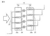
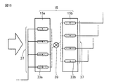
図14に、補助熱交換部15aに配置されている複数の第1伝熱管33aと、補助熱交換部15bに配置されている複数の第2伝熱管33bとに対して、第1伝熱管33aから第2伝熱管33bに至る一つの経路(パス)ごとに設けられた絞り装置39を示す。図15に、複数の第1伝熱管33aのそれぞれを流れてきた冷媒を絞り装置の上流側で合流させ、絞り装置の下流側で再び分岐(分配)させて、複数の第2伝熱管33bのそれぞれに送り出す態様で設けられた絞り装置39を示す。
補助熱交換部15では、絞り装置39の上流側の冷媒の温度に対して、絞り装置39の開度を調整することによって、絞り装置39の下流側の冷媒の温度を調整することができる。すなわち、補助熱交換部15aと補助熱交換部15bとの間(列間)に絞り装置39を設置することで、風上側に位置する補助熱交換部15aを流れる冷媒の温度と、風下側に位置する補助熱交換部15bを流れる冷媒の温度とを分けて調整することができる。
これにより、風上側に位置する補助熱交換部15aをすべて凝縮器として機能させ、風下側位置する補助熱交換部15bをすべて蒸発器として機能させることができる。その結果、実施の形態1において説明したように、室外熱交換器11が蒸発器として作動する運転時において、室外熱交換器11の補助熱交換部15に霜が付着するのを防止することができる。
(第3例)
補助熱交換部15aと補助熱交換部15bとの間に介在させる圧力損失部17として、たとえば、ヘッダ(列間ヘッダ)を用いてもよい。
補助熱交換部15aと補助熱交換部15bとの間に介在させる圧力損失部17として、たとえば、ヘッダ(列間ヘッダ)を用いてもよい。
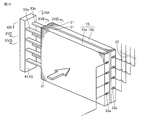
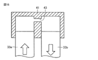
図16に、補助熱交換部15aと補助熱交換部15bとの間に配置させた列間ヘッダ41を示す。図17、図18および図19に示すように、列間ヘッダ41内には、第1伝熱管33aから第2伝熱管33bに至る一つの経路(パス)ごとに、冷媒が流れる流路が設けられている。その流路の途中には、流路の断面積が他の流路の断面積よりも狭められた絞り部43が形成されている。
その絞り部43の幅および絞り部43の流路の長さを調整することによって、列間ヘッダ41の前後において圧力損失を調整することができ、補助熱交換部15aを流れる冷媒の温度と、補助熱交換部15bを流れる冷媒の温度とを分けて調整することができる。これにより、補助熱交換部15aを凝縮器として機能させ、補助熱交換部15bを蒸発器として機能させることができ、室外熱交換器11が蒸発器として作動する運転時において、室外熱交換器11の補助熱交換部15に霜が付着するのを防止することができる。
(第4例)
補助熱交換部15aと補助熱交換部15bとの間に介在させる圧力損失部17として、たとえば、補助熱交換部15aに繋がれるヘッダと補助熱交換部15bに繋がれるヘッダとの2つのヘッダを用いてもよい。
補助熱交換部15aと補助熱交換部15bとの間に介在させる圧力損失部17として、たとえば、補助熱交換部15aに繋がれるヘッダと補助熱交換部15bに繋がれるヘッダとの2つのヘッダを用いてもよい。
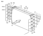
図20に、ヘッダ45a、ヘッダ45bおよびヘッダ接続管47を備えたヘッダを示す。ヘッダ45aは、補助熱交換部15aの第1伝熱管33aに繋がれている。ヘッダ45bは、補助熱交換部15bの第2伝熱管33bに繋がれている。ヘッダ接続管47は、ヘッダ45aとヘッダ45bとの間を繋いでいる。
この場合には、たとえば、ヘッダ接続管47を絞り部43としてその内径等を調整することで、補助熱交換部15aを流れる冷媒の温度と、補助熱交換部15bを流れる冷媒の温度とを分けて調整することができ、室外熱交換器11が蒸発器として作動する運転時において、室外熱交換器11の補助熱交換部15に霜が付着するのを防止することができる。また、ヘッダ45a、45bの流路内に、摩擦損失を生じる流路を別途設けて、その流路の形状を調整することで圧力損失を調整するようにしても、霜の付着を防止することができる。
(第5例)
補助熱交換部15aと補助熱交換部15bとの間に介在させる圧力損失部17として、ヘッダ以外に、たとえば、U字管を用いてもよい。
補助熱交換部15aと補助熱交換部15bとの間に介在させる圧力損失部17として、ヘッダ以外に、たとえば、U字管を用いてもよい。
図21に示すように、第1伝熱管33aから第2伝熱管33bに至る一つの経路(パス)ごとに、U字管49が接続されている。この場合、U字管49の内径を調整することで、補助熱交換部15aを流れる冷媒の温度と、補助熱交換部15bを流れる冷媒の温度とを分けて調整することができ、室外熱交換器11が蒸発器として作動する運転時において、室外熱交換器11の補助熱交換部15に霜が付着するのを防止することができる。
上述した実施の形態において説明した空気調和装置1に用いる冷媒としては、冷媒R410A、冷媒R407C、冷媒R32、冷媒R507A、冷媒HFO1234yf等、どのような冷媒を用いても、室外熱交換器11の補助熱交換部15に霜が付着するのを防止することができる。
冷媒R410Aおよび冷媒R407Cは、混合冷媒であり、特に、非共沸混合冷媒と呼ばれている。非共沸混合冷媒は、湿り蒸気の状態において気相と液相とで組成が異なり、圧力一定のもとでガス冷媒と液冷媒との二相での組成変換と温度変化を伴いながら蒸発または凝縮の相変化を生じるという性質を有する。その非共沸混合冷媒のうち、冷媒R407C等は、相変化の際の温度変化が極めて小さく、特に、疑似共沸混合冷媒と呼ばれている。
冷媒R32および冷媒HFO1234yfは、単一成分の冷媒である。冷媒R507Aは混合冷媒であり、共沸混合冷媒と呼ばれている。共沸混合冷媒は、ある成分比において湿り蒸気の気相と液相の組成が等しく、単一成分の冷媒と同様に、圧力一定のもとで温度一定のままで蒸発または凝縮の相変化が生じるという性質を有する。
このような非共沸混合冷媒、疑似共沸混合冷媒、単一性成分の冷媒または共沸混合冷媒を用いた場合でも、冷媒出口温度が水の凝固点(たとえば、0℃)よりも低い場合において、冷媒入り口温度が、外気温度よりも高く、冷媒出口温度が、外気温度よりも低くなるように運転することで、室外熱交換器11の補助熱交換部15に霜が付着するのを防止することができる。さらに、補助熱交換部15から送り出される冷媒出口温度が、露点温度よりも高くなるように運転させることで、補助熱交換部15に霜が付着するのを確実に防止することができる。
また、空気調和装置に用いる冷凍機油としては、適用される冷媒との相互溶解性を考慮して適合性を有する冷凍機油が使用される。たとえば、冷媒R410A等のフルオロカーボン系冷媒では、アルキルベンゼン油系、エステル油系またはエーテル油系の冷凍機油が使用される。これらの他に、鉱油系またはフッ素油系等の冷凍機油を用いてもよい。
これらの冷凍機油を用いた場合でも、冷媒出口温度が水の凝固点(たとえば、0℃)よりも低い場合において、冷媒入り口温度が、外気温度よりも高く、冷媒出口温度が、外気温度よりも低くなるように運転することで、室外熱交換器11の補助熱交換部15に霜が付着するのを防止することができる。
なお、上述した実施の形態では、冷凍サイクル装置として、空気調和装置を例に挙げて説明した。冷凍サイクル装置としては、空気調和装置に限られるものではなく、たとえば、ヒートポンプ給湯器等の室外熱交換器が空気と熱交換する装置にも適用することができる。また、実施の形態において説明した室外熱交換器を備えた冷凍サイクル装置については、必要に応じて種々組み合わせることが可能である。
今回開示された実施の形態は例示であってこれに制限されるものではない。本発明は上記で説明した範囲ではなく、請求の範囲によって示され、請求の範囲と均等の意味および範囲でのすべての変更が含まれることが意図される。
本発明は、主熱交換部および補助熱交換部を備えた室外熱交換器を有する空気調和装置等の冷凍サイクル装置に有効に利用される。
1 空気調和装置、3 圧縮機、5 室内熱交換器、7 室内ファン、9 絞り装置、11 室外熱交換器、13 主熱交換部、13a、13b 主熱交換部、15 補助熱交換部、15a、15b 補助熱交換部、17 圧力損失部、21 室外ファン、23 四方弁、25 分配器、27 ヘッダ、29 分配器、31 フィン、33a 第1伝熱管、33b 第2伝熱管、33c 第3伝熱管、33d 第4伝熱管、35 冷媒通路、37 冷媒配管、39 絞り装置、41 列間ヘッダ、43 絞り部、45a、45b ヘッダ、47 ヘッダ接続管、49 U字管、51 制御部、53、55、57 温度センサ。
Claims (12)
- 室外熱交換器を備えた冷凍サイクル装置であって、
前記室外熱交換器は、
第1熱交換部と、
前記第1熱交換部と並んで配置された第2熱交換部と
を含み、
前記第1熱交換部は、
板状の複数のフィンと、
前記複数のフィンを貫通するように配置された第1伝熱管と、
前記第1伝熱管が延在する方向と交差する方向に距離を隔てられる態様で、前記複数のフィンを貫通するように配置された第2伝熱管と、
前記第1熱交換部を流れる冷媒の圧力を下げる圧力損失機構と
を備え、
前記室外熱交換器が蒸発器として作動する運転時に、前記第1熱交換部から流出する冷媒の温度が水の凝固点よりも低くなる場合には、前記第1熱交換部に流入する冷媒の温度が外気温度よりも高く、かつ、前記第1熱交換部から流出する冷媒の温度が前記外気温度よりも低くなるように運転する、冷凍サイクル装置。 - 前記運転時には、前記第1熱交換部から流出する冷媒の温度が露点温度よりも高くなるように運転する、請求項1記載の冷凍サイクル装置。
- 前記第1伝熱管は、第1端部と第2端部とを有し、
前記第2伝熱管は、第3端部と第4端部とを有し、
前記第2伝熱管の前記第3端部は、前記第1伝熱管の前記第2端部と繋げられ、
前記第2伝熱管の前記第4端部は、前記第2熱交換部と繋げられた、請求項1記載の冷凍サイクル装置。 - 前記圧力損失機構は、前記第1伝熱管の前記第2端部と前記第2伝熱管の前記第3端部との間に介在させた絞り部を含み、
前記絞り部は、
第1断面積を有する第1流路と、
前記第1断面積よりも小さい第2断面積を有する第2流路と
を含む、請求項3記載の冷凍サイクル装置。 - 前記絞り部は、前記第2流路の前記第2断面積を調整する絞り調整部を含む、請求項4記載の冷凍サイクル装置。
- 前記圧力損失機構は、前記第1伝熱管および前記第2伝熱管を含む、請求項1記載の冷凍サイクル装置。
- 前記第1伝熱管は、長径と短径を有する扁平型断面形状を有する第1扁平管であり、
前記第2伝熱管は、前記扁平型断面形状を有し、前記第1扁平管に対して前記長径の方向に距離を隔てられた第2扁平管である、請求項1記載の冷凍サイクル装置。 - 前記第1伝熱管が配置されている側から前記第2伝熱管が配置されている側へ向かって空気を流す送風部を備え、
冷媒は、前記第1伝熱管から前記第2伝熱管へ流れる、請求項1記載の冷凍サイクル装置。 - 第1熱交換部および前記第1熱交換部と並んで配置された第2熱交換部を含む室外熱交換器であって、
前記第1熱交換部は、
板状の複数のフィンと、
前記複数のフィンを貫通するように配置された第1伝熱管と、
前記第1伝熱管が延在する方向と交差する方向に距離を隔てられる態様で、前記複数のフィンを貫通するように配置された第2伝熱管と、
前記第1伝熱管と前記第2伝熱管との間に介在させた、冷媒の圧力を下げる圧力損失部と
を備えた、室外熱交換器。 - 前記圧力損失部は絞り部を含み、
前記絞り部は、
第1断面積を有する第1流路と、
前記第1断面積よりも小さい第2断面積を有する第2流路と
を含む、請求項9記載の室外熱交換器。 - 前記絞り部は、前記第2流路の前記第2断面積を調整する絞り調整部を含む、請求項10記載の室外熱交換器。
- 前記第1伝熱管は、長径と短径を有する扁平型断面形状を有する第1扁平管であり、
前記第2伝熱管は、前記扁平型断面形状を有し、前記第1扁平管に対して前記長径の方向に距離を隔てられた第2扁平管である、請求項9記載の室外熱交換器。
Priority Applications (6)
| Application Number | Priority Date | Filing Date | Title |
|---|---|---|---|
| CN201680085743.0A CN109312971B (zh) | 2016-06-24 | 2016-06-24 | 制冷循环装置 |
| JP2018523250A JPWO2017221400A1 (ja) | 2016-06-24 | 2016-06-24 | 冷凍サイクル装置 |
| EP16906317.9A EP3477227B1 (en) | 2016-06-24 | 2016-06-24 | Refrigerating cycle device and outdoor heat exchanger used in same |
| PCT/JP2016/068810 WO2017221400A1 (ja) | 2016-06-24 | 2016-06-24 | 冷凍サイクル装置およびそれに用いられる室外熱交換器 |
| ES16906317T ES2844591T3 (es) | 2016-06-24 | 2016-06-24 | Dispositivo de ciclo de refrigeración e intercambiador de calor exterior utilizado en el mismo |
| US16/089,634 US20190128574A1 (en) | 2016-06-24 | 2016-06-24 | Refrigeration cycle apparatus |
Applications Claiming Priority (1)
| Application Number | Priority Date | Filing Date | Title |
|---|---|---|---|
| PCT/JP2016/068810 WO2017221400A1 (ja) | 2016-06-24 | 2016-06-24 | 冷凍サイクル装置およびそれに用いられる室外熱交換器 |
Publications (1)
| Publication Number | Publication Date |
|---|---|
| WO2017221400A1 true WO2017221400A1 (ja) | 2017-12-28 |
Family
ID=60783946
Family Applications (1)
| Application Number | Title | Priority Date | Filing Date |
|---|---|---|---|
| PCT/JP2016/068810 Ceased WO2017221400A1 (ja) | 2016-06-24 | 2016-06-24 | 冷凍サイクル装置およびそれに用いられる室外熱交換器 |
Country Status (6)
| Country | Link |
|---|---|
| US (1) | US20190128574A1 (ja) |
| EP (1) | EP3477227B1 (ja) |
| JP (1) | JPWO2017221400A1 (ja) |
| CN (1) | CN109312971B (ja) |
| ES (1) | ES2844591T3 (ja) |
| WO (1) | WO2017221400A1 (ja) |
Cited By (4)
| Publication number | Priority date | Publication date | Assignee | Title |
|---|---|---|---|---|
| WO2019167839A1 (ja) * | 2018-03-01 | 2019-09-06 | ダイキン工業株式会社 | 熱交換器 |
| WO2022195659A1 (ja) * | 2021-03-15 | 2022-09-22 | 三菱電機株式会社 | 熱交換器および空気調和装置 |
| WO2023234121A1 (ja) * | 2022-05-31 | 2023-12-07 | 株式会社デンソーエアクール | 車載用熱交換器 |
| JP2025060388A (ja) * | 2023-09-29 | 2025-04-10 | ダイキン工業株式会社 | 熱交換器および空気調和装置 |
Families Citing this family (4)
| Publication number | Priority date | Publication date | Assignee | Title |
|---|---|---|---|---|
| JP7170841B2 (ja) * | 2019-03-26 | 2022-11-14 | 三菱電機株式会社 | 熱交換器および冷凍サイクル装置 |
| JP7425282B2 (ja) * | 2019-09-30 | 2024-01-31 | ダイキン工業株式会社 | 蒸発器、およびそれを備えた冷凍サイクル装置 |
| CN111238090B (zh) * | 2020-01-09 | 2021-02-02 | 西安交通大学 | 一种微通道蒸发器及其控制方法 |
| EP4166868A1 (en) * | 2021-10-15 | 2023-04-19 | Carrier Corporation | Evaporator heat exchanger for preventing ice build-up |
Citations (7)
| Publication number | Priority date | Publication date | Assignee | Title |
|---|---|---|---|---|
| JPS49128349A (ja) * | 1973-04-11 | 1974-12-09 | ||
| JPS57109467U (ja) * | 1980-12-26 | 1982-07-06 | ||
| JPH0278844A (ja) * | 1988-09-14 | 1990-03-19 | Hokkaido Electric Power Co Inc:The | 空気調和機 |
| JP2002372320A (ja) * | 2001-06-15 | 2002-12-26 | Matsushita Electric Ind Co Ltd | 冷凍装置 |
| JP2015078830A (ja) * | 2013-09-11 | 2015-04-23 | ダイキン工業株式会社 | 熱交換器および空気調和機 |
| WO2016056063A1 (ja) * | 2014-10-07 | 2016-04-14 | 三菱電機株式会社 | 熱交換器、及び、空気調和装置 |
| WO2016056064A1 (ja) * | 2014-10-07 | 2016-04-14 | 三菱電機株式会社 | 熱交換器、及び、空気調和装置 |
Family Cites Families (7)
| Publication number | Priority date | Publication date | Assignee | Title |
|---|---|---|---|---|
| JPS61197967A (ja) * | 1985-02-26 | 1986-09-02 | 株式会社ボッシュオートモーティブ システム | 冷房サイクル |
| JP4143955B2 (ja) * | 2001-11-30 | 2008-09-03 | 株式会社ティラド | 熱交換器 |
| US7832653B2 (en) * | 2005-02-28 | 2010-11-16 | Daikin Industries, Ltd. | Expansion valve having a grooved valve member and refrigeration device including the same |
| EP2372272A4 (en) * | 2008-12-19 | 2014-10-15 | Daikin Ind Ltd | COOLING SYSTEM |
| JP2013083419A (ja) * | 2011-09-30 | 2013-05-09 | Daikin Industries Ltd | 熱交換器および空気調和機 |
| KR20150047027A (ko) * | 2013-10-23 | 2015-05-04 | 엘지전자 주식회사 | 히트 펌프 |
| WO2016135935A1 (ja) * | 2015-02-27 | 2016-09-01 | ジョンソンコントロールズ ヒタチ エア コンディショニング テクノロジー(ホンコン)リミテッド | 熱交換装置およびこれを用いた空気調和機 |
-
2016
- 2016-06-24 EP EP16906317.9A patent/EP3477227B1/en not_active Not-in-force
- 2016-06-24 ES ES16906317T patent/ES2844591T3/es active Active
- 2016-06-24 CN CN201680085743.0A patent/CN109312971B/zh not_active Expired - Fee Related
- 2016-06-24 US US16/089,634 patent/US20190128574A1/en not_active Abandoned
- 2016-06-24 WO PCT/JP2016/068810 patent/WO2017221400A1/ja not_active Ceased
- 2016-06-24 JP JP2018523250A patent/JPWO2017221400A1/ja active Pending
Patent Citations (7)
| Publication number | Priority date | Publication date | Assignee | Title |
|---|---|---|---|---|
| JPS49128349A (ja) * | 1973-04-11 | 1974-12-09 | ||
| JPS57109467U (ja) * | 1980-12-26 | 1982-07-06 | ||
| JPH0278844A (ja) * | 1988-09-14 | 1990-03-19 | Hokkaido Electric Power Co Inc:The | 空気調和機 |
| JP2002372320A (ja) * | 2001-06-15 | 2002-12-26 | Matsushita Electric Ind Co Ltd | 冷凍装置 |
| JP2015078830A (ja) * | 2013-09-11 | 2015-04-23 | ダイキン工業株式会社 | 熱交換器および空気調和機 |
| WO2016056063A1 (ja) * | 2014-10-07 | 2016-04-14 | 三菱電機株式会社 | 熱交換器、及び、空気調和装置 |
| WO2016056064A1 (ja) * | 2014-10-07 | 2016-04-14 | 三菱電機株式会社 | 熱交換器、及び、空気調和装置 |
Cited By (8)
| Publication number | Priority date | Publication date | Assignee | Title |
|---|---|---|---|---|
| WO2019167839A1 (ja) * | 2018-03-01 | 2019-09-06 | ダイキン工業株式会社 | 熱交換器 |
| WO2022195659A1 (ja) * | 2021-03-15 | 2022-09-22 | 三菱電機株式会社 | 熱交換器および空気調和装置 |
| JPWO2022195659A1 (ja) * | 2021-03-15 | 2022-09-22 | ||
| WO2023234121A1 (ja) * | 2022-05-31 | 2023-12-07 | 株式会社デンソーエアクール | 車載用熱交換器 |
| JPWO2023234121A1 (ja) * | 2022-05-31 | 2023-12-07 | ||
| JP7840404B2 (ja) | 2022-05-31 | 2026-04-03 | 株式会社デンソーエアクール | 車載用熱交換器 |
| JP2025060388A (ja) * | 2023-09-29 | 2025-04-10 | ダイキン工業株式会社 | 熱交換器および空気調和装置 |
| JP7701659B2 (ja) | 2023-09-29 | 2025-07-02 | ダイキン工業株式会社 | 熱交換器および空気調和装置 |
Also Published As
| Publication number | Publication date |
|---|---|
| EP3477227B1 (en) | 2020-12-23 |
| EP3477227A4 (en) | 2019-08-07 |
| EP3477227A1 (en) | 2019-05-01 |
| JPWO2017221400A1 (ja) | 2019-02-28 |
| US20190128574A1 (en) | 2019-05-02 |
| CN109312971A (zh) | 2019-02-05 |
| ES2844591T3 (es) | 2021-07-22 |
| CN109312971B (zh) | 2020-11-06 |
Similar Documents
| Publication | Publication Date | Title |
|---|---|---|
| CN109312971B (zh) | 制冷循环装置 | |
| US20170268790A1 (en) | Air-conditioning device | |
| JPWO2018047416A1 (ja) | 空気調和装置 | |
| JP6479181B2 (ja) | 空気調和装置 | |
| JP2001221526A (ja) | 冷凍空調装置 | |
| JP2007085730A (ja) | 空気調和機、空気調和機の運転方法 | |
| CN109073290B (zh) | 室外单元及具备该室外单元的制冷循环装置 | |
| JP6692495B2 (ja) | 熱交換器及び冷凍サイクル装置 | |
| WO2021065914A1 (ja) | 冷凍装置 | |
| JP2013253726A (ja) | 熱交換システム | |
| JP2013253726A5 (ja) | ||
| JP2012237518A (ja) | 空気調和機 | |
| WO2020235030A1 (ja) | 熱交換器およびそれを用いた冷凍サイクル装置 | |
| JP7458771B2 (ja) | 室外機及びこれを備えた空気調和装置 | |
| JP4983878B2 (ja) | 熱交換器及びこの熱交換器を備えた冷蔵庫、空気調和機 | |
| JP6910436B2 (ja) | 室外ユニットおよび冷凍サイクル装置 | |
| CN117355721A (zh) | 热交换器、具备热交换器的空调装置的室外机、以及具备空调装置的室外机的空调装置 | |
| JP7210609B2 (ja) | 空気調和機 | |
| JPWO2020110301A1 (ja) | 冷凍サイクル装置 | |
| WO2025013244A1 (ja) | 空気調和機の室外機およびそれを備えた空気調和機 | |
| WO2025224966A1 (ja) | 空気調和装置 | |
| JP2022115781A (ja) | 室内機及び室外機 | |
| WO2022215242A1 (ja) | 室外機および空気調和装置 | |
| JP2014129895A (ja) | 空気調和機 | |
| JPH11223361A (ja) | 空気調和機 |
Legal Events
| Date | Code | Title | Description |
|---|---|---|---|
| ENP | Entry into the national phase |
Ref document number: 2018523250 Country of ref document: JP Kind code of ref document: A |
|
| 121 | Ep: the epo has been informed by wipo that ep was designated in this application |
Ref document number: 16906317 Country of ref document: EP Kind code of ref document: A1 |
|
| NENP | Non-entry into the national phase |
Ref country code: DE |
|
| ENP | Entry into the national phase |
Ref document number: 2016906317 Country of ref document: EP Effective date: 20190124 |