WO2017221439A1 - コンタクトレンズおよびその製造方法 - Google Patents
コンタクトレンズおよびその製造方法 Download PDFInfo
- Publication number
- WO2017221439A1 WO2017221439A1 PCT/JP2016/084987 JP2016084987W WO2017221439A1 WO 2017221439 A1 WO2017221439 A1 WO 2017221439A1 JP 2016084987 W JP2016084987 W JP 2016084987W WO 2017221439 A1 WO2017221439 A1 WO 2017221439A1
- Authority
- WO
- WIPO (PCT)
- Prior art keywords
- contact lens
- peripheral
- thickness
- peripheral portion
- meridian
- Prior art date
- Legal status (The legal status is an assumption and is not a legal conclusion. Google has not performed a legal analysis and makes no representation as to the accuracy of the status listed.)
- Ceased
Links
Images


Classifications
-
- G—PHYSICS
- G02—OPTICS
- G02C—SPECTACLES; SUNGLASSES OR GOGGLES INSOFAR AS THEY HAVE THE SAME FEATURES AS SPECTACLES; CONTACT LENSES
- G02C7/00—Optical parts
- G02C7/02—Lenses; Lens systems ; Methods of designing lenses
- G02C7/04—Contact lenses for the eyes
- G02C7/049—Contact lenses having special fitting or structural features achieved by special materials or material structures
-
- G—PHYSICS
- G02—OPTICS
- G02C—SPECTACLES; SUNGLASSES OR GOGGLES INSOFAR AS THEY HAVE THE SAME FEATURES AS SPECTACLES; CONTACT LENSES
- G02C7/00—Optical parts
- G02C7/02—Lenses; Lens systems ; Methods of designing lenses
- G02C7/04—Contact lenses for the eyes
-
- B—PERFORMING OPERATIONS; TRANSPORTING
- B29—WORKING OF PLASTICS; WORKING OF SUBSTANCES IN A PLASTIC STATE IN GENERAL
- B29D—PRODUCING PARTICULAR ARTICLES FROM PLASTICS OR FROM SUBSTANCES IN A PLASTIC STATE
- B29D11/00—Producing optical elements, e.g. lenses or prisms
- B29D11/00009—Production of simple or compound lenses
- B29D11/00038—Production of contact lenses
-
- B—PERFORMING OPERATIONS; TRANSPORTING
- B29—WORKING OF PLASTICS; WORKING OF SUBSTANCES IN A PLASTIC STATE IN GENERAL
- B29D—PRODUCING PARTICULAR ARTICLES FROM PLASTICS OR FROM SUBSTANCES IN A PLASTIC STATE
- B29D11/00—Producing optical elements, e.g. lenses or prisms
- B29D11/00009—Production of simple or compound lenses
- B29D11/0048—Moulds for lenses
-
- G—PHYSICS
- G02—OPTICS
- G02C—SPECTACLES; SUNGLASSES OR GOGGLES INSOFAR AS THEY HAVE THE SAME FEATURES AS SPECTACLES; CONTACT LENSES
- G02C7/00—Optical parts
- G02C7/02—Lenses; Lens systems ; Methods of designing lenses
- G02C7/04—Contact lenses for the eyes
- G02C7/041—Contact lenses for the eyes bifocal; multifocal
- G02C7/044—Annular configuration, e.g. pupil tuned
-
- G—PHYSICS
- G02—OPTICS
- G02C—SPECTACLES; SUNGLASSES OR GOGGLES INSOFAR AS THEY HAVE THE SAME FEATURES AS SPECTACLES; CONTACT LENSES
- G02C7/00—Optical parts
- G02C7/02—Lenses; Lens systems ; Methods of designing lenses
- G02C7/04—Contact lenses for the eyes
- G02C7/048—Means for stabilising the orientation of lenses in the eye
-
- G—PHYSICS
- G02—OPTICS
- G02C—SPECTACLES; SUNGLASSES OR GOGGLES INSOFAR AS THEY HAVE THE SAME FEATURES AS SPECTACLES; CONTACT LENSES
- G02C2202/00—Generic optical aspects applicable to one or more of the subgroups of G02C7/00
- G02C2202/24—Myopia progression prevention
-
- G—PHYSICS
- G02—OPTICS
- G02C—SPECTACLES; SUNGLASSES OR GOGGLES INSOFAR AS THEY HAVE THE SAME FEATURES AS SPECTACLES; CONTACT LENSES
- G02C7/00—Optical parts
- G02C7/02—Lenses; Lens systems ; Methods of designing lenses
- G02C7/04—Contact lenses for the eyes
- G02C7/041—Contact lenses for the eyes bifocal; multifocal
Definitions
- the present invention relates to a contact lens, and more particularly, to a contact lens having a double slab-off as a shaft stability mechanism that increases the thickness of the contact lens when worn as compared to the length as a shaft stability mechanism, and a manufacturing method thereof.
- Visual impairment includes, for example, myopia, hyperopia, astigmatism and presbyopia.
- Myopia and hyperopia are states in which parallel light is focused before or behind the retina with no adjustment, and contact lenses (also called myopia and hyperopia lenses) are one of the methods for correcting myopia and hyperopia. .).
- Astigmatism is a condition where the light from one point in the external world does not converge to a single point in the eye due to the cornea or lens shape not being a clean spherical surface (for example, the refractive index of the eye is different from that of the eye)
- One method of correcting astigmatism is toric contact lenses (also called astigmatic lenses).
- Presbyopia is a state in which the force of focusing the eye from a distant object to a nearby object has been reduced by aging.
- One of the methods for correcting presbyopia is a multifocal contact lens (also referred to as a perspective lens). ).
- the toric contact lens has an optical part formed of a toroidal surface for correcting astigmatism, so it is necessary to stabilize the lens posture. For this reason, an axis stabilization mechanism is provided around the optical unit.
- the shaft stabilization mechanism is divided into truncation (Patent Documents 1 and 2), ridge (Patent Documents 3 and 4), prism ballast (Patent Documents 5 and 6), and double slab-off (Patent Documents 7 and 8).
- the multifocal contact lens the lens power is distributed so that a distance area for far vision and a near area for near vision are arranged in the optical unit (Patent Document 9).
- multifocal toric contact lenses in which an optical part is combined with a toroidal surface for correcting astigmatism and a multifocal power for correcting presbyopia is proceeding (Patent Documents 10 and 11).
- a toric contact lens that is not a multifocal is handled.
- a multifocal contact lens that is not a multifocal is handled.
- it is also referred to as a (multifocal) toric contact lens.
- the following problems arise.
- a multifocal toric contact lens with truncation eg, prior art documents 1 and 2
- it is suitable for a custom-made product for a wearer with a peculiar eye because of its characteristic shape, but is not suitable for mass production.
- the entire lens has a distorted shape as compared with a simple spherical lens, and a foreign object feeling (decrease in wearing feeling) inevitably occurs.
- a multifocal toric contact lens provided with a ridge
- the ridge raised at the lower part of the lens engages with the lower eyelid to obtain positional stability and orientation.
- the engagement between the ridge and the ridge is not suitable for mass production because there are individual differences in the lower eyelid.
- the upper eyelid is likely to hit the convex shape of the ridge, and the wearing feeling is inferior to that of the spherical lens.
- a multifocal toric contact lens having a prism ballast eg, prior documents 5, 6 and 9
- a prism ballast since a prism is formed on the entire lens, the thickness increases from the upper end of the lens to the lower end of the lens, thereby forming a multifocal.
- the prism also remains in the optical part.
- the prism of the optical unit acts as a hindrance to the correction of the distance area and the correction of the near area, and more complicated optical design is required to solve this.
- a ballast is formed in a part of the lens, it is more likely to fall downward than a normal lens.
- a multifocal toric contact lens having a double slab-off (eg, prior art documents 10 and 11), it has left-right symmetry and vertical symmetry, so that it is easy to obtain wearer centering, and a bi-directional optical design is easily exhibited. Further, since no prism is formed on the lens, an effect of preventing an obstacle to the optical design of the distance area and the near area is expected. However, in order to ensure axial stability with double slab off without ballast, it is necessary to have a wall thickness distribution such as forming a thickened area that emphasizes the peripheral part or expanding the thinned part of the peripheral part. Therefore, the lens shape is distorted compared to a spherical lens.
- an object of the present invention is to provide a contact lens and a method of manufacturing the same that can provide an effect of good astigmatism correction (preferably in addition to presbyopia correction). It is another object of the present invention to provide a contact lens and a method for manufacturing the contact lens that can provide a good feeling of wear in addition to excellent centering performance and axial stability.
- a contact lens having a convex front surface and a concave rear surface, the front surface having an optical portion, an edge joining the front surface and the rear surface, a first smoothing portion disposed on the outer periphery of the optical portion,
- the front surface passes through the lens midpoint from the lens upper end portion.
- a first peripheral portion having a shape with a maximum thickness of the contact lens on the horizontal meridian, a portion arranged so as to include the vertical meridian and having the minimum thickness on the vertical meridian Second circumference with shape to ,
- a first peripheral auxiliary portion having a surface shape that is adjacent to the first peripheral portion and has a constant thickness of the contact lens, and the first peripheral auxiliary portion and the second peripheral It is a part which is a continuous surface by connecting the parts, and is constituted by an inclined part having a surface shape which changes the thickness of the contact lens.
- the lens can be easily disposed at the center of the cornea during wearing.
- the accuracy of presbyopia correction by the distance area and the near area assigned to a desired area in the optical unit is improved.
- the first peripheral portion having the maximum thickness is disposed so as to include the horizontal meridian and the second peripheral portion having the minimum thickness is disposed so as to include the vertical meridian orthogonal to the horizontal meridian, One peripheral part is pushed out to the ear / nose side every blink by eyelids.
- the first peripheral portion auxiliary portion having a surface with a constant thickness is adjacent to the first peripheral portion, thereby helping the eyelid to move to the first peripheral portion.
- the first smoothing unit includes an optical unit (for example, an elliptical optical unit having a long axis in the horizontal direction formed for astigmatism correction) and a peripheral unit formed for axis stabilization (for example, the optical unit).
- the second smoothing part smoothly connects the elliptical annular part formed for axial stabilization and the edge of the perfect circle, and the inclined part. Smoothly connects the first peripheral auxiliary portion and the second peripheral portion having different heights (thicknesses).
- the radial width of the peripheral part is constant, and third, the surface area ratio between the peripheral part and the front surface is 1:99 to 10:90.
- the second smoothing unit surrounded by the peripheral part and the edge without narrowing the area for presbyopia correction and astigmatism correction while ensuring the axial stability while the peripheral part is minimized.
- This area can be secured sufficiently.
- the difference from the spherical lens is reduced, and the wearing feeling is improved.
- an aspherical shape that fits the cornea on the rear surface of the lens which greatly affects wearing feeling, by simultaneously providing an optical design and axial stabilization mechanism on the front surface of the lens that simultaneously provide presbyopia correction and astigmatism correction. Can be provided.
- the wall thickness when viewed in the radial direction at the first peripheral portion is constant, and fifth, the wall thickness when viewed in the circumferential direction at the first peripheral portion is perpendicular to the horizontal meridian. Rotating toward the meridian, it decreases as it goes to the sixth meridian.
- the thickness when viewed in the radial direction at the second peripheral part is constant, and seventh, the radial direction of the first peripheral part auxiliary part is constant.
- the width decreases as it rotates from the horizontal meridian to the vertical meridian, and the radial width of the second peripheral portion increases as it rotates from the horizontal meridian to the vertical meridian.
- the boundary line with the peripheral part of is parallel to the horizontal meridian.
- a toric contact lens having an astigmatism correcting function can be provided by forming the optical part with a toroidal surface.
- areas with different frequencies are arranged in an ellipse shape, the distance part for viewing the distance located at the center of the optical part, the power of the distance part arranged on the outer periphery of the distance part
- a first intermediate portion having a frequency distribution that continuously increases from the first intermediate portion, and a near portion for viewing the near portion disposed on the outer periphery of the first intermediate portion are provided.
- regions having different frequencies are arranged in an elliptical shape, the near part arranged in the center of the optical part, the outer part of the near part, and continuously from the frequency of the near part.
- a distance portion disposed on the outer periphery of the second intermediate portion having a decreasing frequency distribution.
- hydrogel or silicone hydrogel as a lens material, it is possible to provide a soft contact lens with good wearing feeling or a silicone hydrogel contact lens with high oxygen permeability.
- the feeling of wearing can be improved by setting the center thickness of the optical part in the range of 0.05 to 0.20 mm.
- the first peripheral auxiliary part is arranged on one of the inner peripheral side and the outer peripheral side. And an inclination part is distribute
- assistant part is distribute
- the shape of the periphery is elliptical and annular with a long axis in the horizontal direction.
- a method for manufacturing a contact lens having a convex front surface and a concave rear surface wherein the front surface includes an optical part, an edge that joins the front face and the rear face, and an outer periphery of the optical part.
- the front surface is a lens.
- It has mirror image symmetry with a vertical meridian extending from the upper end portion through the lens midpoint to the lens lower end portion as a boundary, and also has a mirror image symmetry with respect to a horizontal meridian perpendicular to the vertical meridian and the lens midpoint.
- a first peripheral portion arranged to include a horizontal meridian and having a shape with a maximum thickness of the contact lens on the horizontal meridian, a portion arranged to include a vertical meridian and a vertical meridian Minimum contact lens thickness on the wire
- a second peripheral portion having a shape to be formed, a first peripheral portion auxiliary portion having a surface shape that is a portion adjacent to the first peripheral portion and has a constant thickness of the contact lens, and the first peripheral portion
- a contact lens composed of a sloped part with a surface shape that changes the thickness of the contact lens is a continuous surface that connects the peripheral auxiliary part and the second peripheral part. It is characterized by manufacturing.
- the contact lens of the present invention it is possible to obtain a better wearing feeling as well as centering performance and axial stability than the conventional contact lens. As a result, the optical design for both near and far can be exhibited to the maximum, and astigmatism correction can also be exhibited.
- FIG. 1A is a front view of the contact lens for explaining the configuration of the contact lens of the embodiment of the present invention. It is FIG.1 (b) for demonstrating the structure of the contact lens of embodiment of this invention, and is a side view of the contact lens. It is FIG. 2 (a) for demonstrating the frequency distribution of the optical part in the contact lens, and is a front view of the optical part in the contact lens. FIG. 2B is a graph for explaining the power distribution of the optical part in the contact lens, and is a graph showing the power distribution state of the lens at the OA position.
- FIG. 3 is an enlarged front view of the contact lens near 0 ° to 90 °. It is sectional drawing which shows the method of the definition of the thickness of the contact lens.
- FIG. 1A is a front view of the contact lens for explaining the configuration of the contact lens of the embodiment of the present invention. It is FIG.1 (b) for demonstrating the structure of the contact lens of embodiment of this invention, and is a side view of the contact lens. It is
- FIG. 5A is an enlarged front view of the contact lens in the vicinity of 0 ° to 90 °, illustrating a lens cross section at a predetermined angle of the contact lens.
- FIG. 5B is a schematic diagram showing a lens cross section at the angle shown in FIG. 5A, for explaining a lens cross section at a predetermined angle of the contact lens.
- Fig.6 (a) for demonstrating thickness distribution of the contact lens, and is a front view of the contact lens.
- FIG. 6B is a thickness transition diagram on the circumference M, illustrating the thickness distribution of the contact lens.
- FIG. 6C is a thickness transition diagram on the circumference N for explaining the thickness distribution of the contact lens. It is FIG.
- FIG. 7 for demonstrating the thickness of the peripheral part of the contact lens, and is a front view of the contact lens.
- FIG. 8A is a perspective view of the periphery of the contact lens cut out from around 0 ° to 50 °, illustrating the thickness of the periphery of the contact lens.
- FIG. 8B is a perspective view of the periphery of the contact lens cut out from around 50 ° to 70 °, illustrating the thickness of the periphery of the contact lens.
- FIG. 8C is a perspective view of the periphery of the contact lens cut out from around 70 ° to 90 °, illustrating the thickness of the periphery of the contact lens.
- FIG. 8A is a perspective view of the periphery of the contact lens cut out from around 0 ° to 50 °, illustrating the thickness of the periphery of the contact lens.
- FIG. 8B is a perspective view of the periphery of the contact lens cut out from around 50 ° to 70 °
- FIG. 8D is a perspective view of the periphery of the contact lens cut out from around 50 ° to 90 °, illustrating the thickness of the periphery of the contact lens.
- FIG. 9A for demonstrating the lens cross section along the horizontal meridian in the lens upper end part vicinity of the contact lens, and is the front view which looked at the contact lens from the front side.
- FIG. 9B is a view for explaining a lens cross section along the horizontal meridian near the upper end portion of the contact lens, and shows thickness change profiles of the cut planes CP0, CP100, and CP200 shown in FIG. 9A.
- FIG.9 (c) for demonstrating the lens cross section along the horizontal meridian near the lens upper end part of the contact lens, and is an enlarged view which shows the inside of the dashed-two dotted line L of Fig.9 (a).
- FIG. 9D is a diagram for explaining a lens cross section along the horizontal meridian near the upper end portion of the contact lens, and shows a change in the thickness of cut surfaces CP20 to CP120 in FIG. 9C. .
- FIG. 1a and Table 2a are mainly expressed with parentheses as shown in FIG. 1 (a) and Table 2 (a).
- smoothly connect joint, tie, reduce thickness, etc.
- Constant thickness means that the thickness of the contact lens is equal in a predetermined region (for example, in a plane), and the thickness is uniform and flat. .
- the contact lens 10 (also referred to simply as a lens) is formed by a convex front surface (also referred to as a front curve) 12 and a concave rear surface (also referred to as a base curve) 14. Is done.
- the edge 16 joins the front curve 12 and the base curve 14.
- the front curve 12 is provided with a double slab-off 20 characterized by an optical unit 18 that defines the refractive power for correcting presbyopia and astigmatism of the contact lens 10 and an axis stabilization mechanism.
- the base curve 14 is formed in a rotationally symmetric shape having a multi-stage curve that matches the corneal shape of the wearer. That is, the shape of the base curve 14 is the same shape (concentric circle) even if it is cut in any warp (diameter) direction (described later).
- the parameters of the contact lens 10 include: base curve: 8.6 mm, optical center thickness: 0.09 mm, total diameter: 14.2 mm, myopia power: -3.00 D, astigmatism power: -0.75 D, Axis: 180 ° and add power: + 1.5D are assigned.
- the myopia power is determined by the curvature R1 of the front curve 12 and the curvature R2 of the base curve 14, as shown in FIG.
- the optical unit 18 has an elliptical toroidal surface (also referred to as a toric surface) in which the horizontal direction is the major axis (principal axis) and the vertical direction is the minor axis (secondary axis).
- a toric surface in which the horizontal direction is the major axis (principal axis) and the vertical direction is the minor axis (secondary axis).
- curved surfaces in order to correct astigmatism, curved surfaces (toroidal surfaces) so that the radii of curvature differ between two orthogonal axes (main axis (long axis) and sub-axis (short axis) unless otherwise specified). Is formed.
- the curvature of the major axis (major axis) on the horizontal meridian 24 is larger than the curvature of the minor axis (minor axis) on the vertical meridian 22.
- the length of the ellipse axis and the angle of the ellipse vary depending on the desired refractive power.
- the meridian means an intersecting line between the lens surface (front curve 12 or base curve 14) and a plane including the lens center axis
- the types of meridian include vertical meridian 22, horizontal meridian 24 and angular meridian 26. Each of them is indicated by a one-dot chain line.
- the vertical meridian 22 is a meridian passing through the lens upper end 28 and the lens lower end 30 and the lens midpoint O
- the horizontal meridian 24 is a meridian perpendicular to the vertical meridian 22 and passing through the lens midpoint O.
- the meridian 26 is a meridian on an arbitrary angle (in this case, the angle ⁇ ) with the lens midpoint O as the center, and can be said to be a line extending radially from the lens midpoint O toward the edge 16.
- the radial direction is a direction extending radially from the lens middle point O to an arbitrary distance.
- the circumferential direction is a circumferential direction centered on the lens middle point O. In this embodiment, the circumferential direction is a fan shape surrounded by the lens middle point O, the horizontal meridian 24 and the angular meridian 26. The trajectory indicated by the arc can be said to be the circumferential direction.
- the front curve 12 has mirror image symmetry with the vertical meridian 22 as a boundary. That is, the right half and the left half of the vertical meridian 22 passing through the lens middle point O have the same shape.
- the front curve 12 also has mirror image symmetry with the horizontal meridian 24 as a boundary. That is, the upper half and the lower half of the horizontal meridian 24 passing through the lens middle point O have the same shape.
- the angle of the contact lens 10 is based on the premise that the contact lens 10 is worn on the right eye, the lens upper end portion 28 at a 90 ° position (eyebrow side), and the lens lower end portion 30 at a 270 ° position (jaw Side), of the directions parallel to the horizontal meridian 24, the nose side is defined as a 0 ° position, and the opposite side (ear side) is defined as a 180 ° position.
- the contact lens 10 has mirror image symmetry with respect to the vertical meridian 22 and the horizontal meridian 24. Therefore, the lens cross-sections of 0 ° to 90 ° (counterclockwise) are 180 ° to 90 ° (clockwise), 180 ° to 270 ° (counterclockwise), and 360 ° (0 °) to 270 ° (clockwise). Have the same shape. Examples include 0 ° -50 ° (counterclockwise) lens cross section and 180 ° -130 ° (clockwise), 180 ° -230 ° (counterclockwise) and 0 ° -310 ° (clockwise) lenses.
- the cross section has the same shape as the lens cross section, 50 ° to 70 ° (counterclockwise), 130 ° to 110 ° (clockwise), 230 ° to 250 ° (counterclockwise), and 310 ° to 290 ° (clockwise).
- the lens cross-section is the same shape, and the lens cross-section of 70 ° to 90 ° (counterclockwise) and 110 ° to 90 ° (clockwise), 250 ° to 270 ° (counterclockwise) and 290 ° It has the same shape as the lens cross section at ⁇ 270 ° (clockwise).
- a distance portion 32 for viewing a distance is located at the center of the optical portion 18 and has an intermediate portion 34 having a power distribution that continuously increases from the power of the distance portion. Is disposed around the distance portion 32 and around the first intermediate portion 34, and a near portion 36 for viewing the near portion is disposed as the outermost periphery of the optical portion 18.
- FIG. 2 (b) shows the power distribution state of the lens at the OA position in FIG. 2 (a).
- the horizontal axis indicates the distance x (mm) from the lens middle point O
- the vertical axis indicates the frequency Power (D). Because of the mirror image symmetry with respect to the horizontal meridian 24, the lens power distribution state at the OB position and the lens power distribution state at the OA position shown in FIG.
- the double slab-off 20 includes a first smoothing unit 38 disposed on the outer periphery of the optical unit 18 and an elliptical peripheral unit 40 disposed on the outer periphery of the first smoothing unit 38. , And a second smoothing portion 42 connecting the peripheral portion 40 and the edge 16 is defined.
- the first smoothing unit 38 includes an optical unit 18 that has an elliptical shape due to astigmatism correction, and a peripheral unit 40 that has an elliptical and annular shape (hereinafter, description of the annular shape is omitted) due to axial stability. Tie smoothly. As a result, extra friction does not occur between the lens touched during wearing and the upper and lower eyelids, and a foreign object feeling (decrease in wearing feeling) hardly occurs. In addition, since the first smoothing unit 38 functions as a buffer region, the elliptical equivalence of the peripheral portion 40 is ensured at any refractive power.
- the ratio of the lengths of the countershafts on 22 may coincide with each other.
- the width of the peripheral portion 40 is constant at an arbitrary angle.
- the surface area ratio between the peripheral portion 40 and the front curve 12 is 1:99 to 10:90.
- the second portion is surrounded by the peripheral portion 40 and the edge 16 without securing the axial stability while the peripheral portion 40 is minimized, and without narrowing the presbyopia correction and astigmatism correction regions.
- a sufficient area of the smoothing portion 42 can be secured. As a result, the difference from the spherical lens is reduced, and the wearing feeling is improved.
- the rear surface of the lens which has a large effect on wearing feeling, is aspherical so as to fit the cornea Can be provided.
- the peripheral portion 40 will be described in detail later.
- the second smoothing part 42 smoothly joins the elliptical peripheral part 40 and the edge 16 of the perfect circle. Since the second smoothing unit 42 functions as a buffer region, the equivalence of the elliptical peripheral portion 40 and the equivalence of the perfect circle edge 16 are ensured. Further, by smoothly joining, unnecessary friction between the lens touched at the time of wearing and the upper and lower eyelids is reduced, and a foreign object feeling is hardly generated.
- the thickness T of the contact lens 10 (hereinafter simply referred to as “thickness”) is a perpendicular line perpendicular to the tangent line from any point on the base curve 14 to the front curve 12. Defined as the distance to the intersection.
- the thickness T in the optical unit 18 is defined according to the power for correcting vision.
- the thickness T in the first smoothing part 38, the peripheral part 40 and the second smoothing part 42 excluding the optical part 18 can be changed to a desired value.
- the lens thickness in the radial direction is maximum at the peripheral portion 40 at any angle.
- the thickness from the lens center O through the optical unit 18 and the first smoothing unit 38 to the point m1 gradually increases.
- the thickness gradually increases from the point n1 through the second smoothing section 42 to the edge 16 (ie, “continuously decreases”, and so on).
- the wall thickness from the point m1 to the point n1 is uniform. That is, the thickness of the peripheral portion 40 is maximized at the point m1 (point n1).
- the wall thickness gradually increases from the lens center O through the optical unit 18 and the first smoothing unit 38 to the point m2, and from the point n2 through the second smoothing unit 42 to the edge 16.
- the wall thickness gradually decreases.
- the thickness T from the point m2 to the point n2 is uniform, and at this time, the thickness of the peripheral portion 40 is maximized.
- the thickness from the lens center O to the point m3 through the optical unit 18 and the first smoothing unit 38 gradually increases. After the wall thickness reaches the maximum at the point m3, the wall thickness to the edge 16 through the point n3 and the second smoothing portion 42 gradually decreases.
- the wall thickness T from the lens center O through the optical unit 18 and the first smoothing unit 38 to the point m4 gradually increases, and the edge passes from the point n4 through the second smoothing unit 42 to the edge.
- the wall thickness T over 16 gradually decreases.
- the thickness from the point m4 to the point n4 is uniform. That is, the thickness of the peripheral portion 40 is maximized at the point m4 (point n4).
- the thickness increases from the lens center O to the peripheral portion 40 through the optical portion 18 and the first smoothing portion 38, and from the peripheral portion 40 to the edge 16 through the second smoothing portion 42. Gradually decreases.
- the thickness of the peripheral portion 40 is particularly significant. Details will be described below.
- the thickness of the peripheral portion 40 in the circumferential direction differs for each area divided by a specified angle.
- 6 (b) and 6 (c) are schematic diagrams in which the thickness distribution of the peripheral portion 40 at the predetermined angle shown in FIG. 6 (a) is extracted, and the degree of the thickness distribution is shown in Table 1. It is expressed as follows. Note that the thickness distribution when viewed from the whole lens is shown in FIG.
- the peripheral portion 40 is a portion disposed so as to include the horizontal meridian 24 (for example, straddling), and has a shape that makes the contact lens 10 have a maximum thickness on the horizontal meridian 24.
- the first peripheral portion 44 is a portion arranged so as to include the vertical meridian 22 (for example, straddling), and has a shape that makes the contact lens 10 have a minimum thickness on the vertical meridian 22
- the peripheral portion 46, a first peripheral portion auxiliary portion 48 that is a portion adjacent to the first peripheral portion 44 and has a surface shape that makes the thickness of the contact lens 10 constant, and a first peripheral portion auxiliary portion 48 and the second peripheral portion 46 are connected to each other to form a continuous surface, and the inclined portion 50 has a surface shape that changes the thickness of the contact lens 10.
- the thickness of the first peripheral portion 44 when viewed in the radial direction is constant, and the thickness of the first peripheral portion 44 when viewed in the circumferential direction rotates from the horizontal meridian 24 to the vertical meridian 22. It decreases as you go.
- the wall thickness of the second peripheral portion 46 is constant, and the radial width of the first peripheral portion auxiliary portion 48 decreases as it rotates from the horizontal meridian 24 to the vertical meridian 22, The radial width of the portion 46 increases as it rotates from the horizontal meridian 24 to the vertical meridian 22.
- the boundary line between the inclined portion 50 and the second peripheral portion 46 is parallel to the horizontal meridian 24.
- the wall thickness on the circumference M that is the inner side of the peripheral portion 40 is from a point m1 (0 °).
- the wall thickness Tmc from the point m3 (70 °) to the point m4 (90 °) gradually decreases.
- the point n1 (0 °)
- the wall thickness Tnc from the point n3 (70 °) to the point n4 (90 °) becomes the same.
- the thickness T of the peripheral portion 40 is maximized at the 0 ° position, and is minimized at the 90 ° position.
- FIG. 6B the difference between FIG. 6B and FIG. 6C becomes clear by referring to FIG.
- the circumference M (FIG. 6B) that is the inner side of the peripheral portion 40 (FIG. 6B)
- the circumference N FIG. 6 (c) outside the peripheral portion 40, only one point in the first peripheral auxiliary portion 48 exists only at the point n2 (50 °).
- the inclined portion 50 mainly exists.
- FIGS. 6B and 6C it has been described that the wall thickness gradually increases (or the wall thickness gradually decreases), but any shape can be adopted as long as the wall thickness increases (or decreases). For example, if there is an increase / decrease by a linear function as shown in FIGS. 6B and 6C, an n-order function, an exponential function, or a logarithmic function can be adopted.
- FIG. 8A shows a schematic diagram in which the region indicated by the lattice at 0 ° to 50 ° in FIG. 7 is the first peripheral portion 44 and the peripheral portion 40 is cut out from 0 ° to 50 °.
- the first peripheral portion 44 has a uniform thickness in the radial direction from the horizontal meridian 24 (point m1, point n1) to the boundary (point m2, point n2) of the first peripheral portion auxiliary portion 48. That is, the thickness Tma at the point m1 and the thickness Tna at the point n1 are the same height, and the thickness Tma at the point m2 and the thickness Tna at the point n2 are the same height.
- the first peripheral portion 44 also has a maximum thickness on the 0 ° angular meridian 26 (on the horizontal meridian 24) and a minimum thickness on the 50 ° angular meridian 26. Furthermore, the width Wa in the first peripheral portion 44 has the same distance at any angle. That is, the distance from the point m1 to the point n1 is equal to the distance from the point m2 to the point n2. As described above, the first peripheral portion 44 having the thickest thickness in the peripheral portion 40 is disposed across the horizontal meridian 24, smoothly reduces the thickness from 0 ° to 50 °, and has an arbitrary angle. Has a uniform thickness on the width Wa.
- the contact lens 10 is rotated by being pushed out by the upper or lower eyelid, and the first peripheral portion 44 is on the ear side or the nose side. Move to. Further, the first peripheral portion 44 having a uniform thickness in the radial direction, that is, flat (flat), and the eyelid come into contact with each other at the surface, so that the directivity in the horizontal direction with respect to the contact lens 10 is changed every blink.
- the maximum thickness of the first peripheral portion 44 can be appropriately set within a range that does not hinder the wearing of the contact lens 10. However, in consideration of wearing feeling and the like, the maximum thickness should be less than 0.4 mm. Preferably, it is 0.3 mm or less.
- the area indicated by vertical stripes at 50 ° to 70 ° in FIG. 7 is the first peripheral portion auxiliary portion 48, and a schematic diagram of the peripheral portion 40 cut out from 50 ° to 70 ° is shown in FIG.
- the first peripheral portion auxiliary portion 48 has a flat thickness (equal thickness) from the boundary (point m2, point n2) of the first peripheral portion 44 to the end point (point m3) of the inclined portion 50. That is, the thickness Tmb at the point m2, the thickness Tmb at the point m3, and the thickness Tnb at the point n2 are the same height. Further, the width Wb of the first peripheral portion auxiliary portion 48 becomes shorter from 50 ° to 70 °.
- the width Wb is the longest at 50 °, and the width Wb is the shortest at 70 °.
- a cut surface passing through an arbitrary point ⁇ at 50 ° to 70 ° has a thickness Tmb on the circumference M, a thickness Tnb on the circumference N, and a thickness T ⁇ on the point ⁇ .
- the thickness T ⁇ and the thickness Tmb are the same (equal thickness), and the thickness Tnb is lower than the thickness Tmb (T ⁇ ).
- the flat first peripheral portion auxiliary portion 48 is located between the inclined portion 50 and the first peripheral portion 44.
- the first peripheral portion auxiliary portion 48 functions as a buffer region when the upper and lower eyelids move from the first peripheral portion 44 to the inclined portion 50 or from the inclined portion 50 to the first peripheral portion 44, and smooth Axial stability is provided.
- the first peripheral auxiliary portion 48 mentioned here has a surface shape and has a constant thickness in the surface in both the radial direction and the circumferential direction (the same thickness everywhere in the surface).
- FIG. 8C shows a schematic diagram in which the region indicated by horizontal stripes at 70 ° to 90 ° in FIG. 7 is the second peripheral portion 46, and the peripheral portion 40 is cut from 70 ° to 90 °.
- the second peripheral portion 46 has a flat thickness from the end point (point n3) of the inclined portion 50 to the vertical meridian 22 (point m4, point n4). That is, the thickness Tmc at the point m4, the thickness Tnc at the point n3, and the thickness Tnc at the point n4 are the same height.
- the width Wc in the second peripheral portion 46 increases from 70 ° to 90 °. That is, the width Wc is the shortest at 70 °, and the width Wc is the longest at 90 °.
- a cut surface passing through an arbitrary point ⁇ at 70 ° to 90 ° has a thickness Tmc on the circumference M, a thickness Tnc on the circumference N, and a thickness T ⁇ on the point ⁇ .
- the thickness T ⁇ and the thickness Tnc are the same, and the thickness Tmc is higher than the thickness Tnc (T ⁇ ).
- the second peripheral portion 46 having the thinnest thickness in the peripheral portion 40 is disposed across the vertical meridian 22 as a flat thick surface having a distance in the horizontal direction.
- the contact lens 10 moves for each blink so that the second peripheral portion 46 enters the upper eyelid or the lower eyelid.
- the second peripheral portion 46 mentioned here is uniform in thickness including the portion on the vertical meridian 22 on the premise that the portion on the vertical meridian 22 has a shape with a minimum thickness. Or a linear portion on the vertical meridian 22 otherwise.
- the shape of the peripheral portion 40 is an elliptical ring having the major axis in the direction of the horizontal meridian 24, whereby a wide second peripheral portion 46 on the vertical meridian 22 can be secured.
- the minimum thickness of the second peripheral portion 46 can be appropriately set within a range that does not hinder the wearing of the contact lens 10, but it is necessary to suppress the shaft from continuing to rotate without being stabilized. The numerical value exceeding 0.10 mm is preferable, and 0.15 mm or more is more preferable.
- FIG. 8D shows a schematic diagram in which the region indicated by the oblique lines from 50 ° to 90 ° in FIG. 7 is the inclined portion 50 and the peripheral portion 40 is cut out from 50 ° to 90 °.
- the wall thickness smoothly decreases from the boundary (point m3, point n2) of the first peripheral portion auxiliary portion 48 to the boundary (point m4, point n3) of the second peripheral portion 46. That is, the thickness Tmc at the point m4 and the thickness Tnc at the point n3 are the same height, and the thickness Tmc at the point m4 (thickness Tnc at the point n3) is the thickness Tmb at the point m3 (thickness at the point n2). Lower than Tnb).
- the inclined portion 50 functions as a buffer region by smoothly connecting the flat first peripheral portion 48 and the flat second peripheral portion 46 which are higher (thicker) than the second peripheral portion 46.
- the inclined part 50 mentioned here is a surface shape, Comprising: A wall thickness shall always change even if it sees in a radial direction and a circumferential direction in a surface.
- the area between the predetermined rotation angle ⁇ 1 (50 °) and the rotation angle ⁇ 2 (70 °) from the horizontal meridian 24 (0 °) in the peripheral portion 40 is the first peripheral portion auxiliary.
- the first peripheral portion auxiliary portion 48 is arranged on one of the inner peripheral side and the outer peripheral side of the peripheral portion 40 when ⁇ 1 ⁇ ⁇ 2 and the inclined portion 50 is disposed on the other side of the inner peripheral side or the outer peripheral side, and it is preferable that both of them coexist.
- the first peripheral portion auxiliary portion 48 is disposed on the inner peripheral side, and the inclined portion 50 is provided. It is preferable to arrange them on the outer peripheral side so that both of them coexist.
- first peripheral auxiliary portion 48 (specifically, the boundary line between the first peripheral portion 44 and the first peripheral auxiliary portion 48) is on the meridian of the rotation angle ⁇ 1 (50 °). It is preferable that only the inclined portion 50 is disposed on the meridian at the rotation angle ⁇ 2 (70 °), and only the second peripheral portion 46 is disposed on the vertical meridian 22.
- the effect of the present invention can also be achieved by adopting an arrangement in which the one peripheral portion auxiliary portion 48 and the inclined portion 50 coexist and the second peripheral portion 46 is a linear portion on the vertical meridian 22. That is, within the predetermined rotation angle range of the peripheral portion 40, the first peripheral portion auxiliary portion 48 is set as the inner peripheral side, the inclined portion 50 is set as the outer peripheral side, and one of the features in this embodiment is to coexist both. is there.
- the rotation angle ⁇ 1 can be set as appropriate regardless of the angle, and can be set as appropriate within a range of 45 ° to 60 ° so as to include 50 °.
- the rotation angle ⁇ 2 can also be set as appropriate, and can be set as appropriate within a range of 55 ° or more and less than 90 ° so as to include 70 °.
- the first peripheral portion 44 may be set so that the thickness decreases as it rotates from the horizontal meridian 24 to the vertical meridian 22 as in the above example and Example 1 described later. As in the second embodiment, when rotating from the horizontal meridian 24 to the vertical meridian 22, it may be set so that the thickness is uniform from 0 ° to ⁇ 1, and thereafter the thickness is reduced from ⁇ 1 to ⁇ 2. Absent. Further, the first peripheral portion 44 may have a planar shape as in the above example, or may have a linear shape like the second peripheral portion 46 in the above example. In this case, the following configuration is preferable as the configuration.
- the first peripheral portion 44 has a boundary line only with respect to the first peripheral portion auxiliary portion 48
- the linear or planar second peripheral portion 46 has a boundary line only with respect to the inclined portion 50.
- assistant part 48 and the inclination part 50 coexist between the 1st periphery part 44 and the 2nd periphery part 46, and the 1st periphery part auxiliary
- assistant part 48 is an inner peripheral side
- the inclined portion 50 is preferably disposed on the outer peripheral side.
- the cut planes CP0, CP100, and CP200 shown in FIG. 9A are thick cross-sectional profiles partitioned parallel to the horizontal meridian 24, and the cut plane CP0 is on the horizontal meridian 24 (that is, 0 ° -180 °).
- the cutting plane CP100 is a cutting plane including the peripheral portion 40 in the vicinity of the center
- the cutting plane CP200 is a cutting plane on the second smoothing portion 42.
- the cut surface CP ⁇ b> 0 suddenly increases from the edge 16 and once changes, and then decreases rapidly and gradually decreases toward the vertical meridian 22. That is, a flat surface is formed in a portion where there is no change.
- a region having the same thickness (that is, the first peripheral portion 44) is formed in the vicinity of the horizontal meridian 24 of the peripheral portion 40.
- Cut surface CP100 (the cut surface at the position where the horizontal meridian 24 is moved 5.06 mm in the vertical direction.
- the numerical values shown in FIGS. 9B and 9D are the distances moved in the vertical direction. In this case, after increasing rapidly from the edge 16, it gradually increases toward the vertical meridian 22, and no change is observed in the vicinity of the vertical meridian 22.
- a thickness that increases rapidly from the edge 16 but gradually increases in the vicinity of the vertical meridian 22 is formed.
- the cut surfaces CP20 to CP120 shown in FIG. 9 (d) are cut surfaces in which the vicinity of 0 ° to 90 ° of the upper end portion 28 is divided at equal intervals in parallel with the vicinity of the cut surface CP100 as shown in FIG. 9 (c).
- Each wall thickness profile is shown.
- the cutting plane CP20 is a lens cross section closest to the optical unit 18, and shows from the edge 16 to the vertical meridian 22 through the second smoothing unit 42, the inclined unit 50, and the first smoothing unit 38. Yes. Specifically, from the edge 16 to the vertical meridian 22, the wall thickness suddenly increases, and then the change disappears. A gentle convex shape is formed and smoothly decreased.
- the cut surface CP40 shows from the edge 16 to the vertical meridian 22 through the second smoothing portion 42, the inclined portion 50, and the first smoothing portion 38, but as compared with the cut surface CP20 as a whole. It is changing slowly. Specifically, from the edge 16 to the vertical meridian 22, it suddenly increases and then temporarily disappears, and a gentler convex shape than the cut surface CP20 is formed and smoothly reduced.
- the cut surface CP60 shows from the edge 16 to the vertical meridian 22 through the second smoothing portion 42, the inclined portion 50, the second peripheral portion 46, and the first smoothing portion 38, but compared with the cut surface CP40. Overall, it is changing slowly.
- the cut surface CP80 shows from the edge 16 to the vertical meridian 22 through the second smoothing portion 42, the second peripheral portion 46, and the first smoothing portion 38, but generally gentler than the cut surface CP60. Has changed. Specifically, from the edge 16 to the vertical meridian 22, it suddenly increases and disappears once, and then a convex shape that is gentler than the cut surface CP 60 is formed. After a slight decrease, the change disappears.
- the cut surface CP100 shows from the edge 16 to the vertical meridian 22 through the second smoothing portion 42 and the second peripheral portion 46, but generally changes more slowly than the cut surface CP80. is doing. Specifically, after a sharp increase from the edge 16 to the vertical meridian 22, little change is recognized.
- the cut surface CP120 is a lens cross section closest to the lens upper end portion 28, and shows from the edge 16 through the second smoothing portion 42 to the vertical meridian 22, but generally gentler than the cut surface CP100. Has changed. Specifically, after a sharp increase from the edge 16 to the vertical meridian 22, little change is recognized. In this manner, a flat surface (that is, the second peripheral portion 46) is formed in the vicinity of the vertical meridian 22 of the peripheral portion 40.
- a contact lens base material used when manufacturing the contact lens 10 a polymer that maintains a contact lens shape after polymerization and can be a hydrogel, preferably a copolymer that contains silicone and can be a hydrogel. Any known material (silicone hydrogel material) can be used as it is.
- the contact lens 10 is polymerized by a cast mold manufacturing method, and any material can be used for the mold at this time as long as it has resistance to the monomer mixture, and examples thereof include polypropylene. .
- the center thickness of the contact lens 10 (that is, the center thickness in the optical unit 18) is 0.09 mm.
- the present invention is not limited to this.
- the center thickness is set in the range of 0.05 to 0.20 mm. It is also possible to do.
- the center thickness can be set in the range of 0.05 to 0.20 mm. As the center thickness decreases, the feeling of wearing is improved.
- the above embodiment is a contact lens, the same effect can be obtained for an intraocular lens or the like.
- peripheral portions of Examples 1 to 3 and Comparative Examples 1 to 6 described below all have a shape that has the maximum thickness on the horizontal meridian and a shape that has the minimum thickness on the vertical meridian. have.
- the first peripheral part, the second peripheral part, the first peripheral part auxiliary part, and the inclined part are formed on the elliptical peripheral part, as in the contact lens 10 of the embodiment.
- the second peripheral portion in the first embodiment is a surface having a constant thickness from point m4 to point n4 to point n3
- the inclined portion is a surface from point m4 to point n3 to point n2 to point m3.
- the peripheral part of the peripheral part is a surface of constant thickness from point m3 to point m2 to point n2
- the first peripheral part is a surface of point m2 to point n2 to point n1 to point m1.
- the first peripheral portion is set so that the wall thickness becomes thinner as it rotates from the horizontal meridian to the vertical meridian (that is, as it advances in the circumferential direction from 0 ° to 90 °). is doing.
- the second peripheral portion is a linear portion from point m4 to point n4
- the inclined portion is a surface from point m4 to point n4 to point n3
- the first peripheral portion auxiliary portion is a point.
- the surface of m4-point m3-point n3 is constant
- the first peripheral portion is a surface of point m3-point n3-point n1-point m1.
- the thickness when rotating from the horizontal meridian to the vertical meridian, the thickness is set to be uniform from 0 ° to ⁇ 1, and thereafter the thickness is set to be thin from ⁇ 1 to ⁇ 2.
- the third embodiment has substantially the same configuration as the second embodiment, except that the wall thickness is not constant when viewed in the radial direction in the first peripheral portion (the inner peripheral side and the outer peripheral side). And the thickness is not uniform).
- Comparative Example 1 is a multi-focal toric contact lens having a conventional double slab-off, the maximum thickness portion is located on the horizontal meridian, the thickness on the vertical meridian is thin, and the peripheral portion is It is a true circle (concentric circle).
- the thickness is controlled on one circumferential line. That is, in Comparative Example 1, a portion on one circumference “line” on which the wall thickness control is performed is a peripheral portion.
- the peripheral portion in the present invention includes a “surface shape” first peripheral portion auxiliary portion and a “surface shape” inclined portion.
- Comparative Example 2 is a multifocal toric contact lens in which the thickness is gradually reduced from 0 ° to 90 ° based on Comparative Example 1. However, like the comparative example 1, neither the first peripheral portion auxiliary portion nor the inclined portion is provided, and there is no surface having a constant thickness.
- Comparative Example 3 is a multifocal toric contact lens having a shape in which two thick switching points are provided based on Comparative Example 1. However, even if the portion on the vertical meridian is defined as the second peripheral portion, the outer portion of the portion adjacent to the second peripheral portion ( ⁇ 2 to 90 °) is constant in the circumferential direction. Yes. Therefore, the comparative example 3 does not have an inclined part.
- the comparative example 3 does not have a 1st periphery part auxiliary
- one type of wall thickness is specified as an annular shape at a plurality of angles
- a plurality of types of wall thickness is specified as an annular shape at a plurality of angles.
- Comparative Example 4 is based on Comparative Example 1, with the portion extending from the horizontal meridian to 30 ° from the maximum wall thickness, and by making the wall thickness specified on the vertical meridian closer to the optical part side, This is a multifocal toric contact lens in which a portion is formed. However, like the comparative example 1, it does not have a 1st periphery part auxiliary
- Comparative Example 5 the switching point is changed from 30 ° to 50 ° on the basis of Comparative Example 1, the horizontal meridian is the maximum thickness location, and the thickness specified on the horizontal meridian is brought closer to the optical part side, It is a multifocal toric contact lens in which an elliptical peripheral part is formed. However, like the comparative example 1, it does not have a 1st periphery part auxiliary
- the long axis of the peripheral part in Comparative Examples 3 and 4 is on the horizontal meridian, and the long axis of the peripheral part in Comparative Example 5 is on the vertical meridian.
- the multifocal toric contact lens of Comparative Example 6 has an elliptical peripheral portion, the maximum thickness portion is located on the horizontal meridian, and the maximum thickness portion is located at a portion extending from the horizontal meridian to 20 °. .
- the portion on the vertical meridian is defined as the second peripheral portion, the inner side and the outer side are circumferential in the portion adjacent to the second peripheral portion ( ⁇ 2 to 90 °).
- the wall thickness is constant. Therefore, the comparative example 6 does not have an inclined part.
- Table 4 shows the ratio of the surface area between the front surface and each part of the double slab off.
- the axial stability is remarkably exhibited when the peripheral portion is about 10% or less (preferably less) of the front surface.
- the double slab-off in Comparative Examples 1, 2, 4, and 5 is a boundary line (that is, a point ⁇ ) having no width in the peripheral portion sandwiched between the first smoothing portion and the second smoothing portion. And the point ⁇ are at the same position), the first smoothing part and the peripheral part are divided into the peripheral part and the second smoothing part.
- the peripheral part sandwiched between the first smoothing part and the second smoothing part has a width (that is, a point) ⁇ and point ⁇ have a predetermined distance at any angle), and are divided into a first smoothing portion, a peripheral portion, and a second smoothing portion.
- the multifocal toric contact lenses of Examples 1 to 3 have the first peripheral portion, the second peripheral portion, the first peripheral auxiliary portion, and the inclined portion on the elliptical peripheral portion.
- the shaft stability was superior to those of Comparative Examples 1 to 6 which were not used. Furthermore, it has been revealed that the axial stability is remarkably exhibited when the peripheral portion is about 10% or less (preferably less) of the front surface.
- Table 5 (a) shows the characteristics of Examples 4 and 5 and Comparative Examples 7 to 10
- Table 5 (b) shows the toric contacts used in Examples 4 and 5 and Comparative Examples 7 to 10. The parameters common to each lens are shown. It should be noted that the peripheral portions of Examples 4 and 5 and Comparative Examples 7 to 10 described below all have a shape that has the maximum thickness on the horizontal meridian and a shape that has the minimum thickness on the vertical meridian. have.
- the toric contact lens of Example 4 has the same double slab-off as that of Example 1 except that the optical unit of Example 1 is changed from a presbyopia and astigmatism design to an astigmatism design.
- Example 5 is a toric contact lens having a perfect circle at the periphery based on Example 4.
- Comparative Example 7 is a toric contact lens provided with a conventional double slab-off, and its peripheral part is a perfect circle, and like Comparative Example 1, it does not have a first peripheral part auxiliary part or an inclined part.
- Comparative Example 8 is a toric contact lens based on Comparative Example 6 whose peripheral part is an ellipse. Like Comparative Example 1, it does not have a first peripheral part auxiliary part or an inclined part.
- Comparative Example 9 is a toric contact lens based on Example 4, the peripheral part is a perfect circle, and, like Comparative Example 1, has no first peripheral part auxiliary part or inclined part.
- Comparative Example 10 is a toric contact lens based on Example 4, and the periphery is a perfect circle.
- the first peripheral part is 0 ° to 90 ° (0 ° to 90 ° when inside, 0 ° to 70 ° when outside). Has no slope.
- one type of wall thickness is designated as an annular shape at a plurality of angles
- Comparative Example 8 is designated as an ellipse at a plurality of angles
- Comparative Example 10 is a plurality of The wall thickness of the type is specified as an annular shape at multiple angles.
- the first peripheral portion, the second peripheral portion, the first peripheral portion auxiliary portion, and the inclined portion are partly disposed on the elliptical peripheral portion.
- the shaft stability was superior to Comparative Examples 7 to 10 which did not have all.
- the shape of the peripheral portion is not elliptical but round and annular, but as described above, the effect is sufficiently exhibited. Therefore, the shape of the peripheral portion in the present invention is not limited to an ellipse and an annular shape.
- the contact lens of Example 6 has the double slab-off of Example 1 except that the optical part of Example 1 is changed from a presbyopic and astigmatic design to a myopia / hyperopia design.
- the contact lens of Comparative Example 11 is a conventional myopia / hyperopia contact lens having a double slab-off, and its peripheral part is a perfect circle. Similar to Comparative Example 7, the first peripheral part auxiliary part and the inclined part are inclined. There is no part.
- one type of wall thickness is adjusted by specifying an ellipse at a plurality of angles, and in Example 6, a plurality of types of wall thickness are specified in an annular shape at a plurality of angles.
- Example 6 The wearing test shown in Example 6 and Comparative Example 11 was performed in the same manner as the wearing test shown in Table 3 (a), and the results of the shaft position are shown in Table 8.
- the symbols shown in Table 8 are the same as in Table 3 (b).
- Example 6 of the contact lens including all the inventions of the present application has better axial stability than Comparative Example 11 which is a conventional spherical lens.
- the myopia contact lens of Example 6 is a comparison that does not have the first peripheral part, the second peripheral part, the first peripheral part auxiliary part, and the inclined part in the elliptical peripheral part. Compared to Example 11, the shaft stability was excellent.
- the content described in the problem of the present invention may also occur in the myopia / hyperopia contact lens.
- the myopia / hyperopia contact lens For example, when wearing a lens having a pattern or a pattern among color contact lenses, if the pattern has a vertical direction, it is necessary to wear the lens while making the vertical direction correct. In that case, the pattern cannot be correctly shown to others unless the posture of the lens is stabilized like a toric contact lens.
- the above-mentioned contact lens for myopia also has a problem of stabilizing the posture of the lens, and as a means for solving the problem, by adopting the configuration described in the above embodiment and thus the above embodiment, the lens This has the effect of stabilizing the posture.
- Multifocal contact lens 12 Front (front curve) 14 Rear surface (base curve) 16 Edge 18 Optical unit 20 Double slab off 22 Vertical meridian 24 Horizontal meridian 26 Angular meridian 28 Lens upper end 30 Lens lower end 32 Distance portion 34 First intermediate portion 36 Near portion 38 First smoothing portion 40 Peripheral portion 42 2nd smoothing part 44 1st periphery part 46 2nd periphery part 48 1st periphery part auxiliary
Landscapes
- Health & Medical Sciences (AREA)
- Ophthalmology & Optometry (AREA)
- Physics & Mathematics (AREA)
- General Health & Medical Sciences (AREA)
- General Physics & Mathematics (AREA)
- Optics & Photonics (AREA)
- Engineering & Computer Science (AREA)
- Manufacturing & Machinery (AREA)
- Mechanical Engineering (AREA)
- Eyeglasses (AREA)
Abstract
凸状の前面と凹状の後面とを有するコンタクトレンズであって、前面には、 光学部,エッジ,光学部の外周に配置される第一の平滑化部,第一の平滑化部の外周に配置される周辺部,および周辺部とエッジとをつなぐ第二の平滑化部が画定されたコンタクトレンズにおいて、前面は鏡像対称性を有し、周辺部は、水平経線上で最大肉厚とする形状を備えた第一の周辺部,垂直経線上でコンタクトレンズを最小肉厚とする形状を備えた第二の周辺部,第一の周辺部に隣接された部分であって肉厚を一定とする面形状を備えた第一の周辺部補助部,および第一の周辺部補助部と第二の周辺部とをつないで連続した面とする部分であって肉厚を変化させる面形状を備えた傾斜部によって構成されるコンタクトレンズ並びにその製造方法。
Description
本発明は、コンタクトレンズに関し、特に、装用時におけるコンタクトレンズの肉厚を縦に比べて横を厚くするダブルスラブオフを軸安定性機構として備えるコンタクトレンズおよびその製造方法に関する。
コンタクトレンズは、視覚障害を矯正するためなど広く使用されている。視覚障害には例えば、近視,遠視,乱視および老視がある。近視や遠視は、調節力を働かせない状態で、平行光線が網膜より前または後ろに焦点を結んでしまう状態であり、近視や遠視の矯正方法のひとつにコンタクトレンズ(近視・遠視用レンズともいう。)が挙げられる。乱視は、角膜または水晶体形状がきれいな球面ではない(例えば、眼の縦と横の屈折率が異なる)ことに起因して外界の一点から出た光が眼内で一点に収束しない状態であり、乱視の矯正方法のひとつにトーリックコンタクトレンズ(乱視用レンズともいう。)が挙げられる。老視(老眼)は、眼の焦点を遠くの物体から近くの物体に合わせる力が加齢によって低下した状態であり、老視の矯正方法のひとつにマルチフォーカルコンタクトレンズ(遠近両用レンズともいう。)が挙げられる。
トーリックコンタクトレンズは、光学部が乱視矯正用のトロイダル面で形成されるため、レンズの姿勢を安定化させる必要がある。このため、光学部の周囲に軸安定化機構が設けられる。軸安定化機構には、トランケーション(特許文献1および2),リッジ(特許文献3および4),プリズムバラスト(特許文献5および6)およびダブルスラブオフ(特許文献7および8)に分けられる。また、マルチフォーカルコンタクトレンズには、遠方視するための遠用領域と近方視するための近用領域とが光学部に配置されるようにレンズの度数が分布される(特許文献9)。さらに、光学部に乱視矯正用のトロイダル面と老視補正用の多焦点度数とを組み合わせたマルチフォーカルトーリックコンタクトレンズの開発も進んでいる(特許文献10および11)。
ところで、マルチフォーカルコンタクトレンズにトーリックを組み合わせて軸安定化機構を配備させようとした場合(それに加えてマルチフォーカルではないトーリックコンタクトレンズを扱う場合。以降、(マルチフォーカル)トーリックコンタクトレンズとも称する。)、次のような問題が生じる。トランケーションを備えるマルチフォーカルトーリックコンタクトレンズの場合(例:先行文献1および2)、特徴的な形状のため特異な眼を有する装用者への特注品として向くものの、量産化には適さない。また、シンプルな球面レンズに比べるとレンズ全体が歪な形状となり、異物感(装用感の低下)が必然的に生じる。
リッジを備えるマルチフォーカルトーリックコンタクトレンズの場合(例:先行文献3および4)、レンズ下方部に隆起したリッジが下眼瞼と係合することで位置安定性と配向性とが得られるが、下眼瞼とリッジとの係合具合は下眼瞼に個人差があるため、量産化には適さない。また、上眼瞼はリッジの凸部形状に当たりやすくなり、装用感も球面レンズに比べると劣る。
プリズムバラストを備えるマルチフォーカルトーリックコンタクトレンズの場合(例:先行文献5,6および9)、レンズ全体にプリズムが形成されるためレンズ上端部からレンズ下端部にかけて肉厚が増加し、マルチフォーカルが形成された光学部にもプリズムが残る。この結果、光学部のプリズムが遠用領域の補正や近用領域の補正に阻害要因として働き、これを解消するためにはより複雑な光学設計を必要とする。また、レンズの一部にバラストが形成されるため、通常のレンズよりも下方に落ちやすい。すると、レンズのセンタリングが得られ難く、センタリングを確保するためにレンズのどこかを削って薄くすることでバランスを取る加工の必要性が生じる。加工した場合、球面レンズに比べるとレンズ全体が歪な形状となり、異物感が生じる。
ダブルスラブオフを備えるマルチフォーカルトーリックコンタクトレンズの場合(例:先行文献10および11)、左右対称性および上下対称性を有するので装用者のセンタリングが得やすく遠近両用の光学設計が発揮され易く、また、レンズにプリズムが形成されないので遠用領域や近用領域の光学設計への阻害要因が生じないといった効果が見込まれる。しかし、バラストのないダブルスラブオフで軸安定性を確保するためには、周辺部をより強調した肉厚領域を形成したり、周辺部の薄肉領域を拡張したりといったような肉厚分布が必要になり、球面レンズに比べると歪なレンズ形状になる。また、前面の光学部に乱視矯正と前面の周辺部にダブルスラブオフを設け、後面の光学部にマルチフォーカルを設けた肉厚設計の場合(例:先行文献11)、前面および後面にそれぞれ異なる効果を狙った光学特性を有するので光学設計や加工に特化しやすいものの、前面にも後面にもそれぞれ特徴ある形状を必要とするため、やはりレンズ全体は歪な形状となり、球面レンズに比べると装用感は低下する。
このように、遠近両用の光学設計が最大限発揮され、かつ、乱視矯正も十分に効果を発揮し、その上、装用感が良好な(マルチフォーカル)トーリックコンタクトレンズの開発が求められている。
上述に鑑み、本発明は、良好な乱視矯正(好ましくはそれに加えて老視補正)の効果が得られるコンタクトレンズとその製造方法を提供することを目的とする。また、優れたセンタリング性能と軸安定性とに加えて良好な装用感も得られるコンタクトレンズとその製造方法を提供することを目的とする。
このような課題を解決するために本願発明者らは、以下の構成を備える発明を見出した。即ち、凸状の前面と凹状の後面とを有するコンタクトレンズであって、前面には、光学部,前面と後面とを接合するエッジ,光学部の外周に配置される第一の平滑化部,第一の平滑化部の外周に配置される周辺部,および周辺部とエッジとをつなぐ第二の平滑化部が画定されたコンタクトレンズにおいて、前面は、レンズ上端部からレンズ中点を通りレンズ下端部に至る垂直経線を境界とする鏡像対称性を有すると共に、垂直経線とレンズ中点で直交する水平経線にも鏡像対称性を有し、周辺部は、水平経線を含むように配置された部分であって水平経線上でコンタクトレンズを最大肉厚とする形状を備えた第一の周辺部,垂直経線を含むように配置された部分であって垂直経線上でコンタクトレンズを最小肉厚とする形状を備えた第二の周辺部,第一の周辺部に隣接された部分であってコンタクトレンズの肉厚を一定とする面形状を備えた第一の周辺部補助部,および第一の周辺部補助部と第二の周辺部とをつないで連続した面とする部分であってコンタクトレンズの肉厚を変化させる面形状を備えた傾斜部によって構成されることを特徴とする。
本願発明によれば、レンズ全体が垂直方向および水平方向での鏡像対称性を有することによって装用時にレンズが角膜中心に配置されやすくなる。レンズのセンタリング性能が向上することによって、光学部内の所望の領域に割り当てられた遠用領域および近用領域による老視補正の精度が向上する。
また、最大肉厚の第一の周辺部が水平経線を含むように配置されるとともに最小肉厚の第二の周辺部が水平経線と直交する垂直経線を含むように配置されることにより、第一の周辺部は眼瞼によって瞬目毎に耳/鼻側に押し出される。また、肉厚が一定となる面を有する第一の周辺部補助部が第一の周辺部に隣接することにより、眼瞼が第一の周辺部へ移動することを助ける。この結果、軸安定性が向上し、楕円状の光学部であっても、マルチフォーカルの場合、良好な老視補正が得られる。
そして、第一の平滑化部は、光学部(例えば乱視矯正用に形成された、水平方向に長軸を有する楕円状の光学部)と軸安定用に形成された周辺部(例えば当該光学部に応じて楕円状かつ環状の周辺部)とを滑らかにつなぎ、第二の平滑化部は軸安定用に形成された楕円環状の周辺部と真円のエッジとを滑らかにつなぎ、そして傾斜部は高さ(厚さ)の異なる第一の周辺部補助部と第二の周辺部とを滑らかにつなぐ。こうして、センタリング性能および軸安定性が向上すると共に、良好な装用感が得られる。
また、最大肉厚の第一の周辺部が水平経線を含むように配置されるとともに最小肉厚の第二の周辺部が水平経線と直交する垂直経線を含むように配置されることにより、第一の周辺部は眼瞼によって瞬目毎に耳/鼻側に押し出される。また、肉厚が一定となる面を有する第一の周辺部補助部が第一の周辺部に隣接することにより、眼瞼が第一の周辺部へ移動することを助ける。この結果、軸安定性が向上し、楕円状の光学部であっても、マルチフォーカルの場合、良好な老視補正が得られる。
そして、第一の平滑化部は、光学部(例えば乱視矯正用に形成された、水平方向に長軸を有する楕円状の光学部)と軸安定用に形成された周辺部(例えば当該光学部に応じて楕円状かつ環状の周辺部)とを滑らかにつなぎ、第二の平滑化部は軸安定用に形成された楕円環状の周辺部と真円のエッジとを滑らかにつなぎ、そして傾斜部は高さ(厚さ)の異なる第一の周辺部補助部と第二の周辺部とを滑らかにつなぐ。こうして、センタリング性能および軸安定性が向上すると共に、良好な装用感が得られる。
第二に、周辺部の半径方向の幅は一定であり、第三に、周辺部と前面との表面積比は1:99~10:90である。これによって、周辺部が最小限に抑えられながらも軸安定性が確保されつつ、老視補正用および乱視矯正用の領域を狭めることなく、周辺部とエッジとによって囲われる第二の平滑化部の領域を十分確保することができる。この結果、球面レンズとの差が小さくなり、装用感が向上する。また、老視補正および乱視矯正を同時に備えた光学設計と軸安定化機構とをレンズ前面に一斉に設けることにより、装用感に大きな影響を与えるレンズ後面には角膜に適合するような非球面形状を設けることができる。
第四に、第一の周辺部において半径方向で見たときの肉厚は一定であり、第五に、第一の周辺部において円周方向で見たときの肉厚は、水平経線から垂直経線へと回転して向かうにつれて減少し、第六に、第二の周辺部において半径方向で見たときの肉厚は一定であり、第七に、第一の周辺部補助部の半径方向の幅は、水平経線から垂直経線へと回転して向かうにつれて減少し、第二の周辺部の半径方向の幅は、水平経線から垂直経線へと回転して向かうにつれて増大し、傾斜部と第二の周辺部との境界線は水平経線に対して平行である。これによって、センタリング性能および軸安定性がさらに向上すると共に、良好な装用感も得られる。なお、第一の周辺部補助部の半径方向の幅は、水平経線から垂直経線へと回転して向かうにつれて減少する構成単体を採用してもよい。また、第二の周辺部の半径方向の幅は、水平経線から垂直経線へと回転して向かうにつれて増大する構成単体を採用してもよい。また、傾斜部と第二の周辺部との境界線は水平経線に対して平行である構成単体を採用してもよい。
第八に、光学部をトロイダル面で形成することによって、乱視矯正機能を備えるトーリックコンタクトレンズを提供することができる。
第九に、光学部には、度数の異なる領域が楕円状に配置され、光学部の中心に配置された遠方を見るための遠用部,遠用部の外周に配置され遠用部の度数から連続して増加する度数分布を有する第一の中間部,および第一の中間部の外周に配置された近方を見るための近用部が設けられる。また、第十に、光学部には、度数の異なる領域が楕円状に配置され、光学部の中心に配置された近用部,近用部の外周に配置され近用部の度数から連続して減少する度数分布を有する第二の中間部および第二の中間部の外周に配置された遠用部が設けられる。これによって、マルチフォーカルコンタクトレンズを提供することができ
る。
る。
第十一に、レンズ素材としてハイドロゲルまたはシリコーンハイドロゲルを用いることによって、装用感が良好なソフトコンタクトレンズや酸素透過性の高いシリコーンハイドロゲルコンタクトレンズを提供することができる。
第十二に、光学部における中心肉厚を0.05~0.20mmの範囲とすることにより、装用感の向上を図ることができる。
第十三に、周辺部での水平経線から垂直経線へと回転して向かう所定の回転角度範囲内において、第一の周辺部補助部を内周側または外周側のうちの一方の側に配し、傾斜部を内周側または外周側のうちのもう一方の側に配し、両者を並存させる。それに加え、第十四に、第一の周辺部補助部を内周側に配し、傾斜部を外周側に配し、両者を並存させる。水平経線から垂直経線へと回転させたときの周辺部の領域において、第一の周辺部補助部と傾斜部が並存する領域を存在させ、上記のような細かい構成の設定を採用することにより絶妙な軸安定性が好適に発揮される。
第十五に、周辺部の形状を、水平方向に長軸を有する楕円状かつ環状とする。上記にて例として述べた構成である。これにより、垂直経線上の第二の周辺部を広く確保することができる。
第十六に、凸状の前面と凹状の後面とを有するコンタクトレンズの製造方法であって、前面には、光学部,前面と後面とを接合するエッジ,光学部の外周に配置される第一の平滑化部,第一の平滑化部の外周に配置される周辺部,および周辺部とエッジとをつなぐ第二の平滑化部が画定されたコンタクトレンズの製造方法において、前面は、レンズ上端部からレンズ中点を通りレンズ下端部に至る垂直経線を境界とする鏡像対称性を有すると共に、垂直経線とレンズ中点で直交する水平経線にも鏡像対称性を有し、周辺部は、水平経線を含むように配置された部分であって水平経線上でコンタクトレンズを最大肉厚とする形状を備えた第一の周辺部,垂直経線を含むように配置された部分であって垂直経線上でコンタクトレンズを最小肉厚とする形状を備えた第二の周辺部,第一の周辺部に隣接された部分であってコンタクトレンズの肉厚を一定とする面形状を備えた第一の周辺部補助部,および第一の周辺部補助部と第二の周辺部とをつないで連続した面とする部分であってコンタクトレンズの肉厚を変化させる面形状を備えた傾斜部によって構成されるコンタクトレンズをキャストモールド製法を用いて製造することを特徴とする。
本発明のコンタクトレンズによれば、従来のコンタクトレンズよりもセンタリング性能および軸安定性と共に良好な装用感が得られる。この結果、遠近両用の光学設計を最大限発揮可能となり、乱視矯正も発揮可能となる。
この発明の上述の目的,特徴および利点は、図面を参照して行う以下の実施の形態および実施例の詳細な説明から一層明らかとなろう。以下、本発明の実施形態について図面を参照しながら説明する。なお、本発明は以下の例に限定されるものではない。また、本明細書においては、大きく構成を分けるときには通常の句読点として“、”を付し、小さく構成を分けるときには句読点として“,”を付す。さらに、また、図1a,表2aは、図1(a),表2(a)のように括弧付きで主として表現する。またさらに、本明細書において“滑らかにつなぐ(接合する、結ぶ、肉厚を減少させる等)”とは、つなぐ対象となるもの同士が一つの連続面を形成していることを指し、不連続な鋭い凹凸が突然現れていない状態のことを指す。また、本明細書において“肉厚が一定”とは、コンタクトレンズの肉厚に関し、所定の領域内(例えば面内)において等しい肉厚であることを指し、肉厚が一様、平坦とも言う。
コンタクトレンズ10(単にレンズと称することもある。)は、図1(a)に示すように、凸状の前面(フロントカーブとも言う)12と凹状の後面(ベースカーブとも言う)14とによって形成される。エッジ16は、フロントカーブ12とベースカーブ14とを接合する。
フロントカーブ12には、コンタクトレンズ10の老視および乱視を矯正するための屈折度数を規定する光学部18および軸安定化機構を特徴とするダブルスラブオフ20が設けられる。ベースカーブ14は、装用者の角膜形状に適合するような多段階カーブを有する回転対称形状で形成される。つまり、ベースカーブ14の形状は任意の経(径)方向(後述)で切っても同一形状(同心円)である。なお、このコンタクトレンズ10のパラメータには、ベースカーブ:8.6mm,光学中心厚さ:0.09mm,全直径:14.2mm,近視度数:-3.00D,乱視度数:-0.75D,軸:180°および加入度数:+1.5Dが割り当てられる。近視度数は、図1(b)に示すように、フロントカーブ12の曲率R1とベースカーブ14の曲率R2とによって定まる。
図1(a)に戻って、光学部18は、水平方向を長軸(主軸)としかつ垂直方向を短軸(副軸)とする楕円のトロイダル面(トーリック面とも言う)を有する。つまり、乱視を矯正するために、直交する2つの軸(主軸(長軸)および副軸(短軸)。以降、特記ない限りこの2軸。)において曲率半径が異なるように曲面(トロイダル面)が形成される。この実施例の場合、軸が180°のため、水平経線24上にある主軸(長軸)の曲率は垂直経線22上にある副軸(短軸)の曲率よりも大きい。なお、所望する屈折度数に応じて楕円の軸の長さや楕円の角度が変化する。
ここで、経線とは、レンズ面(フロントカーブ12またはベースカーブ14)とレンズ中心軸線を含む平面との交差線を意味し、経線の種類には、垂直経線22,水平経線24および角経線26があり、いずれも一点鎖線で示している。垂直経線22はレンズ上端部28およびレンズ下端部30とレンズ中点Oを通る経線であり、水平経線24は垂直経線22に直交しレンズ中点Oを通る経線である。角経線26は、レンズ中点Oを中心とした任意の角度(この場合は角度θ)上の経線であり、レンズ中点Oからエッジ16へ向かって放射状に延びる線ともいえる。また、半径方向とは、レンズ中点Oから任意の距離まで放射状に延びる方向のことである。円周方向とは、レンズ中点Oを中心とした円周の方向であり、この実施例の場合には、レンズ中点O,水平経線24および角経線26で囲まれた扇形状のうちの円弧で示される軌跡が円周方向ともいえる。
フロントカーブ12は、垂直経線22を境界とする鏡像対称性を有する。つまり、レンズ中点Oを通る垂直経線22の右半分と左半分とは同一形状である。フロントカーブ12はまた、水平経線24を境界とする鏡像対称性も有する。つまり、レンズ中点Oを通る水平経線24の上半分と下半分とは同一形状である。このように、レンズ全体が垂直方向および水平方向での鏡像対称性を有するため、装用時にレンズが角膜中心に配置されやすくなる。レンズのセンタリング性能が向上することにより、光学部内の所望の領域に割り当てられた遠用領域および近用領域による老視補正の精度が向上する。また、左右の眼に区別なく使用することも可能である。さらに、レンズが眼の上で180°回転しても軸安定性が得られる。
以下の説明においてコンタクトレンズ10の角度は、右眼にコンタクトレンズ10を装用することを前提とし、レンズ上端部28を90°の位置(眉毛側),レンズ下端部30を270°の位置(顎側),水平経線24に平行な方向のうち鼻側を0°の位置,そして反対側(耳側)を180°の位置と定義する。
また、コンタクトレンズ10は垂直経線22および水平経線24に対して鏡像対称性を有する。このため、0°~90°(反時計回り)のレンズ断面は、180°~90°(時計回り),180°~270°(反時計回り)および360°(0°)~270°(時計回り)で同じ形状を有する。一例としては、0°~50°(反時計回り)のレンズ断面と180°~130°(時計回り),180°~230°(反時計回り)および0°~310°(時計回り)のレンズ断面とは同じ形状になり、50°~70°(反時計回り)のレンズ断面と130°~110°(時計回り),230°~250°(反時計回り)および310°~290°(時計回り)のレンズ断面とは同じ形状になり、そして70°~90°(反時計回り)のレンズ断面と110°~90°(時計回り),250°~270°(反時計回り)および290°~270°(時計回り)のレンズ断面とは同じ形状になる。
図2(a)を参照して、コンタクトレンズ10では、遠方を見るための遠用部32が光学部18の中心に,遠用部の度数から連続して増加する度数分布を有する中間部34が遠用部32の周囲に,そして第一の中間部34の周囲に配置された近方を見るための近用部36が光学部18の最外周として配置される。
図2(b)は、図2(a)のO-A位置におけるレンズの度数分布状態を示す。これらの図において横軸はレンズ中点Oからの距離x(mm)を示し、縦軸は度数Power(D)を示す。水平経線24に対して鏡像対称性を有するため、図2(a)に示すO-B位置におけるレンズの度数分布状態とO-A位置におけるレンズの度数分布状態とは同じ曲線を描く。
図3を参照して、ダブルスラブオフ20には、光学部18の外周に配置される第一の平滑化部38,第一の平滑化部38の外周に配置される楕円状の周辺部40,そして周辺部40とエッジ16とをつなぐ第二の平滑化部42とが画定される。
第一の平滑化部38は、乱視矯正に起因して楕円状となる光学部18と軸安定性に起因して楕円状かつ環状(以降、環状については記載省略。)となる周辺部40とを滑らかに結ぶ。これによって、装用中に触れるレンズと上下眼瞼とには余計な摩擦が生じず、異物感(装用感の低下)は発生し難い。また、第一の平滑化部38が緩衝領域として機能することによっていずれの屈折度数であっても周辺部40の楕円状の同等性が確保される。なお、コンタクトレンズ10の軸が180°のとき、光学部18における楕円の主軸の長さおよび副軸の長さの比率と周辺部40における楕円の水平経線24上の主軸の長さおよび垂直経線22上の副軸の長さの比率とが一致しても構わない。
周辺部40の幅は任意の角度で一定である。また、周辺部40とフロントカーブ12との表面積比は1:99~10:90である。このようにして、周辺部40が最小限に抑えられながらも軸安定性を確保し、老視補正用および乱視矯正用の領域を狭めることなく、周辺部40とエッジ16とによって囲われる第二の平滑化部42の領域を十分確保することができる。この結果、球面レンズとの差が小さくなり、装用感が向上する。さらに、老視補正および乱視矯正を同時に備えた光学設計と軸安定化機構とをレンズ前面に一斉に設けることにより、装用感に大きな影響を与えるレンズ後面には角膜に適合するような非球面形状を設けることができる。なお、周辺部40については後で詳しく説明する。
第二の平滑化部42は、楕円状の周辺部40と真円のエッジ16とを滑らかに接合させる。第二の平滑化部42が緩衝領域として機能することによって楕円の周辺部40の同等性と真円のエッジ16の同等性とが確保される。また、滑らかに接合することによって装用時に触れるレンズと上下眼瞼との間の余計な摩擦が低減され、異物感は生じにくい。
次に、コンタクトレンズ10の肉厚について述べる。コンタクトレンズ10の肉厚(以降、単に肉厚と称する。)Tは、図4に示すように、ベースカーブ14上の任意の点からこの任意の点に対する接線に直交する垂線がフロントカーブ12と交わる点までの距離として定義する。光学部18における肉厚Tは視力矯正のために度数に応じで規定される。一方、光学部18を除く第一の平滑化部38,周辺部40および第二の平滑化部42における肉厚Tは所望の値に変更できる。
コンタクトレンズ10の全体で見たとき、半径方向におけるレンズの肉厚は、いずれの角度においても周辺部40で最大となる。図5(a)および(b)を参照して、0°および30°のレンズ断面では、レンズ中心Oから光学部18および第一の平滑化部38を経て点m1にかけての肉厚が徐々に増加し、点n1から第二の平滑化部42を経てエッジ16にかけての肉厚が徐々に減少する(すなわち“連続的に減り続ける”、以降同様)。また、点m1から点n1にかけての肉厚は一様である。つまり、点m1(点n1)のときに周辺部40の肉厚は最大となる。50°のレンズ断面では、レンズ中心Oから光学部18および第一の平滑化部38を経て点m2にかけての肉厚が徐々に増加し、点n2から第二の平滑化部42を経てエッジ16にかけての肉厚が徐々に減少する。また、点m2から点n2にかけての肉厚Tは一様であり、このとき、周辺部40の肉厚は最大となる。70°のレンズ断面では、レンズ中心Oから光学部18および第一の平滑化部38を経て点m3にかけての肉厚は徐々に増加する。点m3で肉厚が最大に達した後、点n3および第二の平滑化部42を経てエッジ16までの肉厚は徐々に減少する。90°のレンズ断面では、レンズ中心Oから光学部18および第一の平滑化部38を経て点m4にかけての肉厚Tが徐々に増加し、点n4から第二の平滑化部42を経てエッジ16にかけての肉厚Tが徐々に減少する。また、点m4から点n4にかけての肉厚は一様である。つまり、点m4(点n4)のときに周辺部40の肉厚は最大となる。このように、レンズ中心Oから光学部18および第一の平滑化部38を経て周辺部40まで肉厚は増加し、周辺部40から第二の平滑化部42を経てエッジ16にかけて肉厚Tは徐々に減少する。
本形態では特に周辺部40の肉厚に大きな特徴がある。以下、詳述する。
円周方向における周辺部40の肉厚は、規定された角度で区分されるエリア毎に異なる。図6(b)および(c)は、図6(a)に示す所定の角度における周辺部40の肉厚分布を抜き出した模式図であり、肉厚分布の程度を表1に示す表記分けのとおりに表現している。なお、レンズ全体で見たときの肉厚分布は後述の図7にて示している。
円周方向における周辺部40の肉厚は、規定された角度で区分されるエリア毎に異なる。図6(b)および(c)は、図6(a)に示す所定の角度における周辺部40の肉厚分布を抜き出した模式図であり、肉厚分布の程度を表1に示す表記分けのとおりに表現している。なお、レンズ全体で見たときの肉厚分布は後述の図7にて示している。
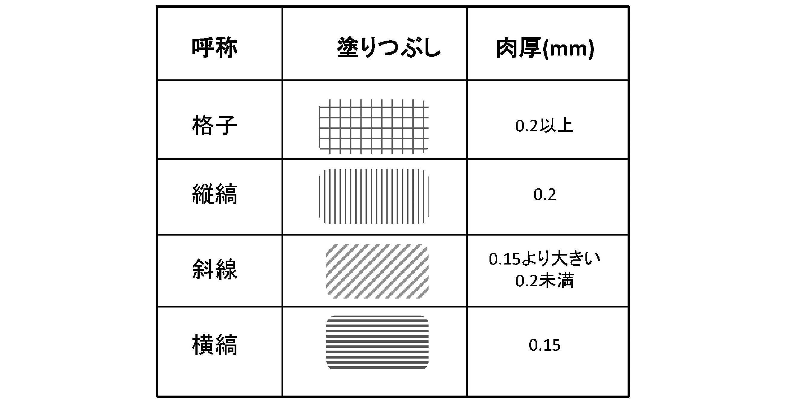
周辺部40は、図7に示すように、水平経線24を含むように(一例としては跨って)配置された部分であって水平経線24上でコンタクトレンズ10を最大肉厚とする形状を備えた第一の周辺部44,垂直経線22を含むように(一例としては跨って)配置された部分であって垂直経線22上でコンタクトレンズ10を最小肉厚とする形状を備えた第二の周辺部46,第一の周辺部44に隣接された部分であってコンタクトレンズ10の肉厚を一定とする面形状を備えた第一の周辺部補助部48,そして第一の周辺部補助部48と第二の周辺部46とをつないで連続した面とする部分であってコンタクトレンズ10の肉厚を変化させる面形状を備えた傾斜部50によって構成される。第一の周辺部44において半径方向で見たときの肉厚は一定であり、第一の周辺部44において円周方向で見たときの肉厚は、水平経線24から垂直経線22へと回転して向かうにつれて減少する。第二の周辺部46の肉厚は一定であり、第一の周辺部補助部48の半径方向の幅は、水平経線24から垂直経線22へと回転して向かうにつれて減少し、第二の周辺部46の半径方向の幅は、水平経線24から垂直経線22へと回転して向かうにつれて増大する。傾斜部50と第二の周辺部46との境界線は水平経線24に対して平行となる。
周辺部40の内側となる円周M上(以降、単に内周側、内側とも言う。)の肉厚に関しては、図7および図6(b)に示すように、点m1(0°)から点m2(50°=所定の回転角度θ1)までの肉厚Tmaは徐々に減少し、点m2(50°)から点m3(70°=所定の回転角度θ2)までの肉厚Tmbは同等であり、点m3(70°)から点m4(90°)までの肉厚Tmcは徐々に減少する。また、周辺部40の外側となる円周N上(以降、単に外周側、外側とも言う。)の肉厚に関しては、図7および図6(c)に示すように、点n1(0°)から点n2(50°=所定の回転角度θ1)までの肉厚Tnaは徐々に減少し、点n2(50°)から点n3(70°=所定の回転角度θ2)までの肉厚Tnbは徐々に減少し、点n3(70°)から点n4(90°)までの肉厚Tncは同等となる。この結果、周辺部40の肉厚Tは、0°の位置で最大となる一方、90°の位置で最小となる。
ここで、図6(b)と(c)との相違は、図7を参照することにより明らかとなる。例えば、周辺部40の内側となる円周M上(図6(b))においては、点m2(50°)から点m3(70°)まで、肉厚Tが一定となる第一の周辺部補助部48となっている。その一方、周辺部40の外側となる円周N上(図6(c))においては、第一の周辺部補助部48における一点が点n2(50°)のみに存在するだけであり、代わりに傾斜部50が主として存在する。それに加え、周辺部40の内側となる円周M上(図6(b))においては、第二の周辺部46における一点が点m4(90°)のみに存在するだけであるが、周辺部40の外側となる円周N上(図6(c))においては、点n3(70°)から点n4(90°)までが第二の周辺部46となる。なお、周辺部40の内側となる円周M上の点m2(50°)においては、第一の周辺部44と第一の周辺部補助部48とが並存しているものとみなす。他の境界においても同様の扱いとする。ただし、内容を正確に表現する場合は、いずれか一方のみが存在すると規定しても構わない。
ここで、図6(b)と(c)との相違は、図7を参照することにより明らかとなる。例えば、周辺部40の内側となる円周M上(図6(b))においては、点m2(50°)から点m3(70°)まで、肉厚Tが一定となる第一の周辺部補助部48となっている。その一方、周辺部40の外側となる円周N上(図6(c))においては、第一の周辺部補助部48における一点が点n2(50°)のみに存在するだけであり、代わりに傾斜部50が主として存在する。それに加え、周辺部40の内側となる円周M上(図6(b))においては、第二の周辺部46における一点が点m4(90°)のみに存在するだけであるが、周辺部40の外側となる円周N上(図6(c))においては、点n3(70°)から点n4(90°)までが第二の周辺部46となる。なお、周辺部40の内側となる円周M上の点m2(50°)においては、第一の周辺部44と第一の周辺部補助部48とが並存しているものとみなす。他の境界においても同様の扱いとする。ただし、内容を正確に表現する場合は、いずれか一方のみが存在すると規定しても構わない。
なお、図6(b)および(c)では、肉厚が徐々に増加する(もしくは、肉厚が徐々に減少する)と説明したが、増加(もしくは減少)すればどのような形状でも採用が可能であり、例えば、図6(b)および(c)で示すような1次関数による増減もあれば、n次関数,指数関数や対数関数を採用することも可能である。
図7の0°~50°における格子で示す領域が第一の周辺部44であり、周辺部40の0°から50°までを切り出した模式図を図8(a)に示す。第一の周辺部44は、水平経線24上(点m1,点n1)から第一の周辺部補助部48の境界(点m2,点n2)にかけて、半径方向に一様な肉厚となる。つまり、点m1における肉厚Tmaと点n1における肉厚Tnaとは同じ高さであり、点m2における肉厚Tmaと点n2における肉厚Tnaとは同じ高さである。第一の周辺部44はまた、0°の角経線26上(水平経線24上)のときに最大肉厚となり、50°の角経線26上のときに最小肉厚となる。さらに、第一の周辺部44における幅Waは、いずれの角度でも同じ距離を有する。つまり、点m1から点n1までの距離と点m2から点n2までの距離とは等しい。このように、周辺部40において最も厚い肉厚を有する第一の周辺部44は、水平経線24上に跨って配置され、0°から50°にかけて肉厚を滑らかに減少させると共に、任意の角度における幅Wa上で一様な肉厚を有する。水平経線24上に最大肉厚の第一の周辺部44が配置されることにより、上眼瞼もしくは下眼瞼に押し出されてコンタクトレンズ10が回転し、第一の周辺部44は耳側もしくは鼻側へ移動する。また、半径方向に一様な肉厚すなわち平坦(平ら)となる第一の周辺部44と眼瞼とが面で接することにより、コンタクトレンズ10に対して水平方向への指向性が瞬目毎に与えられる。なお、第一の周辺部44の最大肉厚は、コンタクトレンズ10を装用する際に支障ない範囲で適宜設定することが可能であるが、装用感等を鑑み、0.4mm未満とするのが好ましく、0.3mm以下とするのがより好ましい。
図7の50°~70°における縦縞で示す領域が第一の周辺部補助部48であり、周辺部40の50°から70°までを切り出した模式図を図8(b)に示す。第一の周辺部補助部48は、第一の周辺部44の境界(点m2,点n2)から傾斜部50の端点(点m3)にかけて、平坦な肉厚(等しい肉厚)となる。つまり、点m2における肉厚Tmb,点m3における肉厚Tmbおよび点n2における肉厚Tnbは同じ高さである。また、第一の周辺部補助部48における幅Wbは50°から70°にかけて短くなる。つまり、50°のときに幅Wbは最長となり、70°のときに幅Wbは最短となる。なお、50°~70°における任意の点αを通る切断面には、円周M上の肉厚Tmb,円周N上の肉厚Tnbおよび点α上の肉厚Tαが在る。このとき、肉厚Tαと肉厚Tmbとは同じ肉厚(等しい肉厚)であり、肉厚Tnbは肉厚Tmb(Tα)よりも低い。このように、平らな第一の周辺部補助部48は傾斜部50と第一の周辺部44との間に位置する。これによって、第一の周辺部補助部48は、第一の周辺部44から傾斜部50へもしくは傾斜部50から第一の周辺部44へ上下眼瞼が移動する際の緩衝領域として機能し、円滑な軸安定性が与えられる。なお、ここで挙げた第一の周辺部補助部48は、面形状であって、面内において半径方向でも円周方向でも肉厚が一定である(面内のどこでも同じ肉厚である)ものとする。
図7の70°~90°における横縞で示す領域が第二の周辺部46であり、周辺部40の70°から90°までを切り出した模式図を図8(c)に示す。第二の周辺部46は、傾斜部50の端点(点n3)から垂直経線22上(点m4,点n4)にかけて、平坦な肉厚となる。つまり、点m4における肉厚Tmc,点n3における肉厚Tncおよび点n4における肉厚Tncは同じ高さである。また、第二の周辺部46における幅Wcは70°から90°にかけて広がる。つまり、70°のときに幅Wcは最短となり、90°のときに幅Wcは最長となる。なお、70°~90°における任意の点βを通る切断面には、円周M上の肉厚Tmc,円周N上の肉厚Tncおよび点β上の肉厚Tβが在る。このとき、肉厚Tβと肉厚Tncとは同じ肉厚であり、肉厚Tmcは肉厚Tnc(Tβ)よりも高い。このようにして、周辺部40において最も薄い肉厚を有する第二の周辺部46は水平方向に距離を有するような平らな肉厚面として垂直経線22上に跨って配置される。水平経線24と直交する垂直経線22上に第二の周辺部46が配置されることにより、上眼瞼もしくは下眼瞼に第二の周辺部46が入り込むようにコンタクトレンズ10が瞬目毎に動く。なお、ここで挙げた第二の周辺部46は、垂直経線22上の部分が最小肉厚となる形状を有することを前提とした上で、垂直経線22上の部分を含む厚さ一様の部分、そうでなければ垂直経線22上の線状の部分とする。
ちなみに、本形態においては周辺部40の形状は水平経線24方向を長軸とする楕円環状であるが、これにより、垂直経線22上の第二の周辺部46を広く確保することができる。また、第二の周辺部46の最小肉厚は、コンタクトレンズ10を装用する際に支障ない範囲で適宜設定することが可能であるが、軸が安定せずに回転し続けることを抑制すべく、0.10mmを越えた数値とするのが好ましく、0.15mm以上とするのがより好ましい。
図7の50°~90°における斜線で示す領域が傾斜部50であり、周辺部40の50°から90°までを切り出した模式図を図8(d)に示す。傾斜部50では、第一の周辺部補助部48の境界(点m3,点n2)から第二の周辺部46の境界(点m4,点n3)にかけて、滑らかに肉厚が減少する。つまり、点m4における肉厚Tmcと点n3における肉厚Tncとは同じ高さであり、点m4における肉厚Tmc(点n3における肉厚Tnc)は点m3における肉厚Tmb(点n2における肉厚Tnb)よりも低い。第二の周辺部46よりも高く(厚く)平坦な第一の周辺部補助部48と平らな第二の周辺部46とを滑らかにつなぐことにより、傾斜部50は緩衝領域として機能する。なお、ここで挙げた傾斜部50は、面形状であって、面内において半径方向に見ても円周方向に見ても肉厚が常に変化するものとする。
上記の内容をまとめると、周辺部40における、水平経線24(0°)からの所定の回転角度θ1(50°)から回転角度θ2(70°)までの間の領域は第一の周辺部補助部48と傾斜部50とで構成され、θ1<θ<θ2においては、第一の周辺部補助部48を周辺部40の内周側または外周側のうちの一方の側に配し、傾斜部50を内周側または外周側のうちのもう一方の側に配し、両者を並存させるのが好ましく、その中でも、第一の周辺部補助部48を内周側に配し、傾斜部50を外周側に配し、両者を並存させるのが好ましい。回転角度θ2(70°)から垂直経線22(90°)までの間の領域は傾斜部50と第二の周辺部46とで構成され、θ2<θ<90°においては、傾斜部50を周辺部40の内周側または外周側のうちの一方の側に配し、肉厚が一様な面形状を有する場合の第二の周辺部46を内周側または外周側のうちのもう一方の側に配し、両者を並存させるのが好ましく、その中でも、傾斜部50を内周側に配し、第二の周辺部46を外周側に配し、両者を並存させるのが好ましい。そして、回転角度θ1(50°)の角経線上には第一の周辺部補助部48のみ(具体的に言うと第一の周辺部44と第一の周辺部補助部48との境界線)が配され、回転角度θ2(70°)の角経線上には傾斜部50のみが配され、垂直経線22上には第二の周辺部46のみが配されるのが好ましい。
このように、水平経線24から垂直経線22へと回転させたときの周辺部40の領域において、第一の周辺部補助部48と傾斜部50が並存する領域、そして傾斜部50と第二の周辺部46とが並存する領域を設け、上記のような細かい構成の設定を採用することにより絶妙な軸安定性が好適に発揮される。ただし、後述の実施例2に示すように、周辺部40における水平経線24(0°)からの所定の回転角度θ(実施例2だと50°)から90°までの間の領域においては第一の周辺部補助部48と傾斜部50とが並存するような配置を採用し、第二の周辺部46を垂直経線22上の線状の部分としても、本願発明の効果を奏する。つまり、周辺部40の所定の回転角度範囲内において、第一の周辺部補助部48を内周側とし、傾斜部50を外周側とし、両者を並存させるのも本形態における特徴の一つである。
ちなみに回転角度θ1は上記角度にとらわれず適宜設定することが可能であって50°を含むように45°以上60°以下の範囲内で適宜設定することが可能である。同様に、回転角度θ2も適宜設定することが可能であって70°を含むように55°以上90°未満の範囲内で適宜設定することが可能である。ただし、後述の実施例が示すように、θ1は50°、θ2は70°に設定するのが好ましい。なお、0°<θ1<θ2<90°という関係を有する。
また、第一の周辺部44は、上記の例および後述の実施例1のように、水平経線24から垂直経線22へと回転するにつれて肉厚が薄くなるように設定しても構わないし、後述の実施例2のように、水平経線24から垂直経線22へと回転する際に0°~θ1までは一様の肉厚としその後θ1~θ2では肉厚が薄くなるように設定しても構わない。また、上記の例のように第一の周辺部44は面形状であっても構わないし、上記の一例における第二の周辺部46のように線形状であっても構わない。その際に好ましい構成としては、以下の構成が挙げられる。すなわち、第一の周辺部44は第一の周辺部補助部48のみに対して境界線を有し、線状または面形状の第二の周辺部46は傾斜部50のみに対して境界線を有する。そして、第一の周辺部補助部48および傾斜部50は、第一の周辺部44と第二の周辺部46との間にて並存し、第一の周辺部補助部48は内周側、傾斜部50は外周側に配されるのが好ましい。
図9(a)に示す切断面CP0,CP100およびCP200は、水平経線24に対して平行に区切られた肉厚断面プロフィールであり、切断面CP0は水平経線24上(つまり、0°-180°)の切断面であり、切断面CP100は中心付近に周辺部40が含まれる切断面であり、そして切断面CP200は第二の平滑化部42上の切断面である。図9(b)を参照して、切断面CP0では、エッジ16から急激に増加し一旦変化がなくなった後、急激に減少し、垂直経線22に向かってなだらかに減少している。つまり、変化のない箇所には平坦な面が形成されている。このように、周辺部40の水平経線24付近には肉厚が等しい領域(つまり、第一の周辺部44)が形成されている。切断面CP100(水平経線24を垂直方向へと5.06mm移動させた箇所での切断面。図9(b),(d)に記載の数値はそのように垂直方向へと移動させた距離を意味する。)では、エッジ16から急激に増加した後、垂直経線22にかけてなだらかに増加し、垂直経線22付近では変化が認められない。切断面CP200では、エッジ16から急激に増加するものの、垂直経線22付近ではなだらかに増加する肉厚が形成される。このようにして、ダブルスラブオフ20では、切断面CP200の中央付近(つまり、90°付近)よりも切断面CP0の両凸部付近(つまり、0°および180°付近)の方がはるかに高い(厚い)ことがわかる。
図9(d)に示す切断面CP20~CP120は、図9(c)で示すように、上端部28の0°~90°付近を切断面CP100付近と平行に等間隔に区切られた切断面毎の肉厚断面プロフィールを示している。切断面CP20は、光学部18に一番近い箇所のレンズ断面であり、エッジ16から第二の平滑化部42,傾斜部50および第一の平滑化部38を経て垂直経線22までを示している。具体的には、エッジ16から垂直経線22にかけて、肉厚が急に増加した後一旦変化が無くなり、なだらかな凸状が形成され、滑らかに減少している。切断面CP40は、切断面CP20と同様、エッジ16から第二の平滑化部42,傾斜部50および第一の平滑化部38を経て垂直経線22までを示すが、切断面CP20に比べて全体的に緩やかに変化している。具体的には、エッジ16から垂直経線22にかけて、急に増加した後一旦変化が無くなり、切断面CP20よりも緩やかな凸状が形成され、滑らかに減少している。切断面CP60は、エッジ16から第二の平滑化部42,傾斜部50,第二の周辺部46および第一の平滑化部38を経て垂直経線22までを示すが、切断面CP40に比べて全体的に緩やかに変化している。具体的には、エッジ16から垂直経線22にかけて、急に増加した後一旦変化が無くなり、切断面CP40よりも緩やかな凸状が形成され、滑らかに減少した後変化が無くなっている。切断面CP80は、エッジ16から第二の平滑化部42,第二の周辺部46および第一の平滑化部38を経て垂直経線22までを示すが、切断面CP60に比べて全体的に緩やかに変化している。具体的には、エッジ16から垂直経線22にかけて、急に増加し一旦変化が無くなった後、切断面CP60よりも緩やかな凸状が形成され、少し減少した後変化が無くなっている。切断面CP100は、切断面CP80と同様、エッジ16から第二の平滑化部42および第二の周辺部46を経て垂直経線22までを示すが、切断面CP80に比べて全体的に緩やかに変化している。具体的には、エッジ16から垂直経線22にかけて、急に増加した後、あまり変化が認められない。切断面CP120は、レンズ上端部28に一番近い箇所のレンズ断面であり、エッジ16から第二の平滑化部42を経て垂直経線22までを示すが、切断面CP100に比べて全体的に緩やかに変化している。具体的には、エッジ16から垂直経線22にかけて、急に増加した後、あまり変化が認められない。このようにして、周辺部40の垂直経線22付近には平坦な面(つまり、第二の周辺部46)が形成されている。
なお、コンタクトレンズ10を製造する際に使用するコンタクトレンズ基材としては、重合後にコンタクトレンズ形状を保持し、ハイドロゲルとなりうる重合体、好ましくは、シリコーンを含有し、ハイドロゲルとなりうる共重合体であればよく、従来からソフトコンタクトレンズ用機材として知られているもの(シリコーンハイドロゲル材料)をそのまま用いることができる。さらに、コンタクトレンズ10は、キャストモールド製法により重合されるが、このときのモールド型の材質としては、モノマー混合液に対して耐性を有するものであればいかなるものでもよく、例えば、ポリプロピレンがあげられる。
また、このコンタクトレンズ10の光学部18には、中心に遠用部32,第一の中間部34および近用部36を配置しているが、光学部18の老視用の光学設計はこれに限らず、例えば、中心に近用部,近用部の外周に配置され近用部の度数から連続して減少する度数分布を有する第二の中間部および第二の中間部の外周に配置された遠用部を設けることも可能である。
さらに、このコンタクトレンズ10の中心肉厚(つまり光学部18における中心肉厚)は0.09mmであるが、これに限らず、例えば、中心肉厚を0.05~0.20mmの範囲に設定することも可能である。つまり、軸安定化機構がプリズムバラストの場合、中心肉厚はバラスト効果を発揮させるために中心肉厚を薄くすることが困難であるが、軸安定化機構がダブルスラブオフの場合、瞬目による瞼と眼球との挟み込み効果を利用しているため、中心肉厚を0.05~0.20mmの範囲に設定することが可能となる。中心肉厚が薄くなるほど、装用感の向上が図られる。
加えて、上記実施形態はコンタクトレンズであるが、眼内レンズ等についても同様の効果を得ることができる。
以下、本願発明に係る実施例について説明する。なお、説明の便宜上、符号は省略する。
[マルチフォーカルトーリックコンタクトレンズ]
以下、実施例のマルチフォーカルトーリックコンタクトレンズ(遠近両用レンズともいう。)を装用した9つの試験について説明する。表2(a)には、実施例1~3と比較例1~6との特徴を示し、表2(b)には、実施例1~3と比較例1~6とにて使用されたマルチフォーカルトーリックコンタクトレンズの各々に共通するパラメータを示す。なお、表2(a)に示す切り換え点や角度については、試験対象のレンズ全てが上下左右に鏡像対称性を有するため、鼻側の眉毛あたりの角度(0°~90°)のみ表記する。例えば、「50°」の場合「130°,230°,310°」が該当し、「50°~70°」の場合「110°~130°,230°~250°,290°~310°」が該当する。なお、以降に述べる実施例1~3と比較例1~6の周辺部はいずれも、水平経線上にて最大肉厚となる形状を有し、かつ、垂直経線上において最小肉厚となる形状を有している。
以下、実施例のマルチフォーカルトーリックコンタクトレンズ(遠近両用レンズともいう。)を装用した9つの試験について説明する。表2(a)には、実施例1~3と比較例1~6との特徴を示し、表2(b)には、実施例1~3と比較例1~6とにて使用されたマルチフォーカルトーリックコンタクトレンズの各々に共通するパラメータを示す。なお、表2(a)に示す切り換え点や角度については、試験対象のレンズ全てが上下左右に鏡像対称性を有するため、鼻側の眉毛あたりの角度(0°~90°)のみ表記する。例えば、「50°」の場合「130°,230°,310°」が該当し、「50°~70°」の場合「110°~130°,230°~250°,290°~310°」が該当する。なお、以降に述べる実施例1~3と比較例1~6の周辺部はいずれも、水平経線上にて最大肉厚となる形状を有し、かつ、垂直経線上において最小肉厚となる形状を有している。


実施例1~3のマルチフォーカルトーリックコンタクトレンズは、実施形態のコンタクトレンズ10と同様、楕円状の周辺部に第一の周辺部,第二の周辺部,第一の周辺部補助部および傾斜部を有する。例えば、実施例1における第二の周辺部は点m4-点n4-点n3の肉厚一定の面であり、傾斜部は点m4-点n3-点n2-点m3の面であり、第一の周辺部補助部は点m3-点m2-点n2の肉厚一定の面であり、第一の周辺部は点m2-点n2-点n1-点m1の面となる。また、実施例1においては、第一の周辺部は、水平経線から垂直経線へと回転するにつれて(つまり、0°から90°へと円周方向に進むにつれて)肉厚が薄くなるように設定している。また、実施例2における第二の周辺部は点m4-点n4の線状の部分であり、傾斜部は点m4-点n4-点n3の面であり、第一の周辺部補助部は点m4-点m3-点n3の肉厚一定の面であり、第一の周辺部は点m3-点n3-点n1-点m1の面となる。また、実施例2においては、水平経線から垂直経線へと回転する際に0°からθ1までは一様の肉厚としその後θ1からθ2までは肉厚が薄くなるように設定している。さらに、実施例3は、実施例2とほぼ同じ構成を備えるが、相違するのは、第一の周辺部において、半径方向で見たときに肉厚が一定ではない(内周側と外周側とで肉厚が一様ではない)ところである。
一方、比較例1は、従来のダブルスラブオフを備えたマルチフォーカルトーリックコンタクトレンズであり、最大肉厚箇所は水平経線上に位置し、垂直経線上の肉厚は薄い形状であり、周辺部は真円(同心円)である。ただし、比較例1においては、上記の実施例とは異なり、一つの円周線上にて肉厚の制御を行っている。つまり、比較例1においては、肉厚制御を行っている一つの円周“線”上の部分が周辺部となる。その一方、本発明における周辺部は、“面形状”の第一の周辺部補助部および“面形状”の傾斜部を備えたものである。そのため、比較例1での一つの円周線上の部分は、当然のごとく面形状の第一の周辺部補助部および面形状の傾斜部を備えず、本発明における周辺部とは全く異なるものである。だからこそ、後述の表4(各部の面積比)において、比較例1だと周辺部が円周線上の部分となり面積が無いため、周辺部の欄には面積比の値が無い。その代りに、周辺部を円周線として考えた上で第一の平滑化部や第二の平滑化部と該周辺部とを合わせた形で面積比を記載している。また、円周線上の部分とはいえ、最小肉厚部分や最大肉厚部分は一応有する場合もあるため、第二の周辺部や第一の周辺部については比較例1にも一応存在すると仮定して、以降、説明している。
また、比較例2は、比較例1を基に0°から90°にかけて肉厚を徐々に薄肉化したマルチフォーカルトーリックコンタクトレンズである。ただし、比較例1と同様に第一の周辺部補助部も傾斜部も有さず、肉厚一定の面もない。比較例3は、比較例1を基に肉厚の切換点を2箇所設けた形状を有するマルチフォーカルトーリックコンタクトレンズである。ただし、仮に垂直経線上の部分を第二の周辺部と規定したとしても、第二の周辺部に隣接する部分(θ2~90°)においては外側が円周方向にて肉厚一定となっている。そのため、比較例3は傾斜部を有しない。また、そもそも面内において肉厚が等しくなる面形状となる第一の周辺部補助部を有さない。そのため、比較例3は第一の周辺部補助部も傾斜部も有さない。なお、比較例1および2は1種類の肉厚を複数の角度で円環状に指定し、比較例3は複数種類の肉厚を複数の角度で円環状に指定している。
さらに、比較例4は、比較例1を基に水平経線上から30°にかけての部分を最大肉厚箇所とし、垂直経線上で指定する肉厚を光学部側に近づけることにより、楕円状の周辺部が形成されるマルチフォーカルトーリックコンタクトレンズである。ただし、比較例1と同様に第一の周辺部補助部も傾斜部も有さない。比較例5は、比較例1を基に切換点を30°から50°に変更し、水平経線上を最大肉厚箇所とし、水平経線上で指定する肉厚を光学部側に近づけることにより、楕円状の周辺部が形成されるマルチフォーカルトーリックコンタクトレンズである。ただし、比較例1と同様に第一の周辺部補助部も傾斜部も有さない。なお、比較例3および4における周辺部の長軸は水平経線上となり、比較例5における周辺部の長軸は垂直経線上としている。
さらにまた、比較例6のマルチフォーカルトーリックコンタクトレンズは、楕円状の周辺部を有し、最大肉厚箇所は水平経線上に位置し、水平経線から20°にかけての部分に最大肉厚箇所を有する。ただし、比較例3と同様、仮に垂直経線上の部分を第二の周辺部と規定したとしても、第二の周辺部に隣接する部分(θ2~90°)においては内側も外側も円周方向で肉厚が一定となっている。そのため、比較例6は傾斜部を有しない。そのため、傾斜部と隣接する第一の周辺部補助部も特定できず、結果的に比較例6は第一の周辺部補助部も傾斜部も有さない。なお、比較例4および5は1種類の肉厚を複数の角度で楕円状に指定し、比較例6は複数種類の肉厚を複数の角度で楕円状に指定している。
装用テストは、年代の異なる被験者5名の片眼に対して行った。装用経過15分後の軸位置を確認し、この結果を表3(a)に示す。なお、表3(b)は表3(a)中に示された記号の説明である。なお、評価の基準としては、以下の2つの条件“平均点が6.0点以上”および“×評価すなわち評価点0の被験者がいない”を満たす場合を適用とし、それ以外の場合を不適用とした。
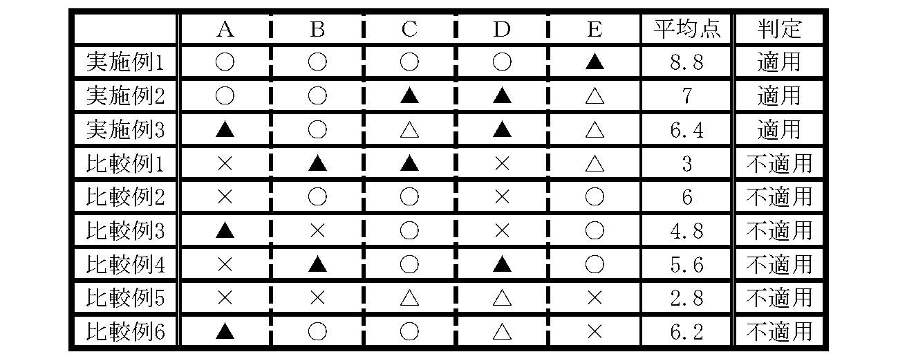

表3(a)に示すように、実施例1~3は比較例1~6に比べ軸安定性が優れていた。
表4は、前面とダブルスラブオフの各部位との表面積の比率を示す。ここでは、周辺部が前面の約10%以下(好ましくは未満)の場合に軸安定性を顕著に発揮することが明らかとなった。なお、比較例1,2,4,および5におけるダブルスラブオフは、第一の平滑化部と第二の平滑化部とに挟まれた周辺部には幅のない境界線(つまり、点αと点βとが同じ位置)のため、第一の平滑化部および周辺部と周辺部および第二の平滑化部とに分けられる。一方、実施例1~3,比較例3,比較例6におけるダブルスラブオフは、第一の平滑化部と第二の平滑化部とに挟まれた周辺部は幅を有するので(つまり、点αと点βとはいずれの角度でも所定の距離を有する)、第一の平滑化部,周辺部および第二の平滑化部に分けられる。

以上の結果をまとめると、実施例1~3のマルチフォーカルトーリックコンタクトレンズは、楕円状の周辺部に第一の周辺部,第二の周辺部,第一の周辺部補助部および傾斜部を有さない比較例1~6に対し、軸安定性が優れていた。さらに、周辺部が前面の約10%以下(好ましくは未満)の場合に軸安定性を顕著に発揮することが明らかとなった。
[トーリックコンタクトレンズ]
他の実施例では、本願発明を用いたトーリックコンタクトレンズ(乱視用レンズともいう。)を装用した6つの試験について説明する。表5(a)には、実施例4および5並びに比較例7~10の特徴を示し、表5(b)には、実施例4および5並びに比較例7~10にて使用されたトーリックコンタクトレンズの各々に共通するパラメータを示す。なお、以降に述べる実施例4および5と比較例7~10の周辺部はいずれも、水平経線上にて最大肉厚となる形状を有し、かつ、垂直経線上において最小肉厚となる形状を有している。
他の実施例では、本願発明を用いたトーリックコンタクトレンズ(乱視用レンズともいう。)を装用した6つの試験について説明する。表5(a)には、実施例4および5並びに比較例7~10の特徴を示し、表5(b)には、実施例4および5並びに比較例7~10にて使用されたトーリックコンタクトレンズの各々に共通するパラメータを示す。なお、以降に述べる実施例4および5と比較例7~10の周辺部はいずれも、水平経線上にて最大肉厚となる形状を有し、かつ、垂直経線上において最小肉厚となる形状を有している。


実施例4のトーリックコンタクトレンズは、実施例1の光学部を老視用および乱視用の設計から乱視用の設計に変更するのみであり、実施例1と同様のダブルスラブオフを有する。実施例5は、実施例4に基づいて周辺部を真円とするトーリックコンタクトレンズである。
一方、比較例7は、従来のダブルスラブオフを備えたトーリックコンタクトレンズであり、周辺部は真円であり、比較例1と同様に第一の周辺部補助部も傾斜部も有さない。比較例8は、比較例6を基にした周辺部が楕円であるトーリックコンタクトレンズであり、比較例1と同様に第一の周辺部補助部も傾斜部も有さない。比較例9は、実施例4を基にしたトーリックコンタクトレンズであり、周辺部は真円であり、比較例1と同様に第一の周辺部補助部も傾斜部も有さない。比較例10は、実施例4を基にしたトーリックコンタクトレンズであり、周辺部は真円である。第二の周辺部は有するものの、0°~90°までが第一の周辺部(内側だと0°~90°、外側だと0°~70°)となり、第一の周辺部補助部および傾斜部を有さない。なお、比較例7,9は1種類の肉厚を複数の角度で円環状に指定し、比較例8は複数種類の肉厚を複数の角度で楕円状に指定し、そして比較例10は複数種類の肉厚を複数の角度で円環状に指定している。
実施例4および5並びに比較例7~10の装用テストも表3(a)で示す装用テストと同様に実施した。軸位置の結果を表6に示す。なお、表6で示す記号はそれぞれ表3(b)と同様である。

以上の結果をまとめると、実施例4および5のトーリックコンタクトレンズは、楕円状の周辺部に第一の周辺部,第二の周辺部,第一の周辺部補助部および傾斜部を一部ないし全て有さない比較例7~10に対し、軸安定性が優れていた。なお、実施例5においては周辺部の形状を楕円状ではなく真円状かつ環状としているが、上述の通り十分に効果を発揮している。そのため、本願発明における周辺部の形状は楕円状かつ環状に限られない。
[近視・遠視用コンタクトレンズ]
また他の実施例では、本願発明を用いた近視・遠視用コンタクトレンズを装用した2つの試験について説明する。表7(a)には、実施例6および比較例11の特徴を示し、表7(b)には、実施例6と比較例11にて使用されたコンタクトレンズの各々に共通するパラメータを示す。
また他の実施例では、本願発明を用いた近視・遠視用コンタクトレンズを装用した2つの試験について説明する。表7(a)には、実施例6および比較例11の特徴を示し、表7(b)には、実施例6と比較例11にて使用されたコンタクトレンズの各々に共通するパラメータを示す。


実施例6のコンタクトレンズは、実施例1の光学部が老視用かつ乱視用の設計から近視・遠視用の設計に変わったのみであり、実施例1のダブルスラブオフを有する。
一方、比較例11のコンタクトレンズは、従来のダブルスラブオフを有する近視・遠視用のコンタクトレンズであり、周辺部は真円であり、比較例7と同様、第一の周辺部補助部および傾斜部を有さない。なお、比較例11は1種類の肉厚を複数の角度で楕円状に指定しで調整し、実施例6は複数種類の肉厚を複数の角度で円環状に指定している。
実施例6および比較例11に示す装用テストも表3(a)で示す装用テストと同様に実施し、軸位置の結果を表8に示す。なお、表8で示す記号はそれぞれ表3(b)と同様である。

表8に示すように、本願発明を全て備えるコンタクトレンズの実施例6は従来の球面レンズである比較例11に比べ軸安定性が優れていることが明らかとなった。
以上の結果をまとめると、実施例6の近視用コンタクトレンズは、楕円状の周辺部に第一の周辺部,第二の周辺部,第一の周辺部補助部および傾斜部を有さない比較例11に対し、軸安定性が優れていた。
なお、近視・遠視用コンタクトレンズにおいても、本発明の課題にて述べた内容、すなわちレンズの姿勢を安定化させるという課題が生じ得る。例えば、カラーコンタクトレンズのうち柄や模様が入っているレンズを装用する場合、模様に上下方向がある場合、上下方向を正しくしつつレンズを装用する必要が出てくる。その場合、トーリックコンタクトレンズのようにレンズの姿勢を安定化させなければ模様を正しく他者に見せることができない。そのため、上記の近視用コンタクトレンズにおいてもレンズの姿勢を安定化させるという課題が生じ、それを解決する手段として、上記の実施例ひいては上記の実施形態に記載された構成を採用することにより、レンズの姿勢を安定化させるという効果を奏する。
10 マルチフォーカルコンタクトレンズ
12 前面(フロントカーブ)
14 後面(ベースカーブ)
16 エッジ
18 光学部
20 ダブルスラブオフ
22 垂直経線
24 水平経線
26 角経線
28 レンズ上端部
30 レンズ下端部
32 遠用部
34 第一の中間部
36 近用部
38 第一の平滑化部
40 周辺部
42 第二の平滑化部
44 第一の周辺部
46 第二の周辺部
48 第一の周辺部補助部
50 傾斜部
L 二点鎖線
12 前面(フロントカーブ)
14 後面(ベースカーブ)
16 エッジ
18 光学部
20 ダブルスラブオフ
22 垂直経線
24 水平経線
26 角経線
28 レンズ上端部
30 レンズ下端部
32 遠用部
34 第一の中間部
36 近用部
38 第一の平滑化部
40 周辺部
42 第二の平滑化部
44 第一の周辺部
46 第二の周辺部
48 第一の周辺部補助部
50 傾斜部
L 二点鎖線
Claims (16)
- 凸状の前面と凹状の後面とを有するコンタクトレンズであって、
前記前面には、光学部,前記前面と前記後面とを接合するエッジ,前記光学部の外周に配置される第一の平滑化部,前記第一の平滑化部の外周に配置される周辺部,および前記周辺部と前記エッジとをつなぐ第二の平滑化部が画定されたコンタクトレンズにおいて、
前記前面は、レンズ上端部からレンズ中点を通りレンズ下端部に至る垂直経線を境界とする鏡像対称性を有すると共に、前記垂直経線と前記レンズ中点で直交する水平経線にも鏡像対称性を有し、
前記周辺部は、前記水平経線を含むように配置された部分であって前記水平経線上で前記コンタクトレンズを最大肉厚とする形状を備えた第一の周辺部,前記垂直経線を含むように配置された部分であって前記垂直経線上で前記コンタクトレンズを最小肉厚とする形状を備えた第二の周辺部,前記第一の周辺部に隣接された部分であって前記コンタクトレンズの肉厚を一定とする面形状を備えた第一の周辺部補助部,および前記第一の周辺部補助部と前記第二の周辺部とをつないで連続した面とする部分であって前記コンタクトレンズの肉厚を変化させる面形状を備えた傾斜部によって構成されることを特徴とするコンタクトレンズ。 - 前記周辺部の半径方向の幅は一定であることを特徴とする請求項1に記載のコンタクトレンズ。
- 前記周辺部と前記前面との表面積比は1:99~10:90であることを特徴とする請求項1に記載のコンタクトレンズ。
- 前記第一の周辺部において半径方向で見たときの肉厚は一定であることを特徴とする請求項1に記載のコンタクトレンズ。
- 前記第一の周辺部において円周方向で見たときの肉厚は、前記水平経線から前記垂直経線へと回転して向かうにつれて減少することを特徴とする請求項1に記載のコンタクトレンズ。
- 前記第二の周辺部において半径方向で見たときの肉厚は一定であることを特徴とする請求項1に記載のコンタクトレンズ。
- 前記第一の周辺部補助部の半径方向の幅は、前記水平経線から前記垂直経線へと回転して向かうにつれて減少し、前記第二の周辺部の半径方向の幅は、前記水平経線から前記垂直経線へと回転して向かうにつれて増大し、前記傾斜部と前記第二の周辺部との境界線は前記水平経線に対して平行であることを特徴とする請求項6に記載のコンタクトレンズ。
- 前記光学部は、乱視矯正機能を有するトロイダル面で形成されることを特徴とする請求項1~7のいずれか一項に記載のコンタクトレンズ。
- 前記光学部は、
度数の異なる領域が楕円状に配置され、
前記光学部の中心に配置された遠方を見るための遠用部,前記遠用部の外周に配置され前記遠用部の度数から連続して増加する度数分布を有する第一の中間部および前記第一の中間部の外周に配置された近方を見るための近用部を備えることを特徴とする請求項1~8のいずれか一項に記載のコンタクトレンズ。 - 前記光学部は、
度数の異なる領域が楕円状に配置され、
前記光学部の中心に配置された近用部,前記近用部の外周に配置され前記近用部の度数から連続して減少する度数分布を有する第二の中間部および前記第二の中間部の外周に配置された遠用部を備えることを特徴とする請求項1~8のいずれか一項に記載のコンタクトレンズ。 - 前記コンタクトレンズの素材はハイドロゲルまたはシリコーンハイドロゲルであることを特徴とする請求項1~10のいずれか一項に記載のコンタクトレンズ。
- 前記光学部における中心肉厚は0.05~0.20mmの範囲に含まれることを特徴とする請求項1~11のいずれか一項に記載のコンタクトレンズ。
- 前記周辺部での前記水平経線から前記垂直経線へと回転して向かう所定の回転角度範囲内において、前記第一の周辺部補助部を内周側または外周側のうちの一方の側に配し、前記傾斜部を内周側または外周側のうちのもう一方の側に配し、両者を並存させることを特徴とする請求項1~12のいずれか一項に記載のコンタクトレンズ。
- 前記第一の周辺部補助部を内周側に配し、前記傾斜部を外周側に配し、両者を並存させることを特徴とする請求項13に記載のコンタクトレンズ。
- 前記周辺部の形状を、水平方向に長軸を有する楕円状かつ環状とすることを特徴とする請求項1~14のいずれか一項に記載のコンタクトレンズ。
- 凸状の前面と凹状の後面とを有するコンタクトレンズの製造方法であって、
前記前面には、光学部,前記前面と前記後面とを接合するエッジ,前記光学部の外周に配置される第一の平滑化部,前記第一の平滑化部の外周に配置される周辺部,および前記周辺部と前記エッジとをつなぐ第二の平滑化部が画定されたコンタクトレンズの製造方法において、
前記前面は、レンズ上端部からレンズ中点を通りレンズ下端部に至る垂直経線を境界とする鏡像対称性を有すると共に、前記垂直経線と前記レンズ中点で直交する水平経線にも鏡像対称性を有し、
前記周辺部は、前記水平経線を含むように配置された部分であって前記水平経線上で前記コンタクトレンズを最大肉厚とする形状を備えた第一の周辺部,前記垂直経線を含むように配置された部分であって前記垂直経線上で前記コンタクトレンズを最小肉厚とする形状を備えた第二の周辺部,前記第一の周辺部に隣接された部分であって前記コンタクトレンズの肉厚を一定とする面形状を備えた第一の周辺部補助部,および前記第一の周辺部補助部と前記第二の周辺部とをつないで連続した面とする部分であって前記コンタクトレンズの肉厚を変化させる面形状を備えた傾斜部によって構成される前記コンタクトレンズをキャストモールド製法を用いて製造することを特徴とするコンタクトレンズの製造方法。
Priority Applications (4)
| Application Number | Priority Date | Filing Date | Title |
|---|---|---|---|
| CN201680085426.9A CN109073914B (zh) | 2016-06-20 | 2016-11-25 | 隐形眼镜及其制造方法 |
| US16/301,708 US11231598B2 (en) | 2016-06-20 | 2016-11-25 | Contact lens and method for manufacturing the same |
| EP16906355.9A EP3474064B1 (en) | 2016-06-20 | 2016-11-25 | Contact lens and method for manufacturing same |
| KR1020187031908A KR102553989B1 (ko) | 2016-06-20 | 2016-11-25 | 콘택트 렌즈 및 그 제조 방법 |
Applications Claiming Priority (2)
| Application Number | Priority Date | Filing Date | Title |
|---|---|---|---|
| JP2016121418A JP6646531B2 (ja) | 2016-06-20 | 2016-06-20 | コンタクトレンズおよびその製造方法 |
| JP2016-121418 | 2016-06-20 |
Publications (1)
| Publication Number | Publication Date |
|---|---|
| WO2017221439A1 true WO2017221439A1 (ja) | 2017-12-28 |
Family
ID=60783461
Family Applications (1)
| Application Number | Title | Priority Date | Filing Date |
|---|---|---|---|
| PCT/JP2016/084987 Ceased WO2017221439A1 (ja) | 2016-06-20 | 2016-11-25 | コンタクトレンズおよびその製造方法 |
Country Status (6)
| Country | Link |
|---|---|
| US (1) | US11231598B2 (ja) |
| EP (1) | EP3474064B1 (ja) |
| JP (1) | JP6646531B2 (ja) |
| KR (1) | KR102553989B1 (ja) |
| CN (1) | CN109073914B (ja) |
| WO (1) | WO2017221439A1 (ja) |
Cited By (1)
| Publication number | Priority date | Publication date | Assignee | Title |
|---|---|---|---|---|
| TWI908593B (zh) * | 2025-01-23 | 2025-12-11 | 視陽光學股份有限公司 | 隱形眼鏡 |
Families Citing this family (15)
| Publication number | Priority date | Publication date | Assignee | Title |
|---|---|---|---|---|
| US20180196281A1 (en) * | 2017-01-06 | 2018-07-12 | eyeBrain Medical, Inc. | Prismatic contact lens |
| WO2019245002A1 (ja) | 2018-06-20 | 2019-12-26 | 国立大学法人大阪大学 | 眼装着用レンズの製造方法および眼装着用レンズ |
| US20220334409A1 (en) * | 2019-09-25 | 2022-10-20 | Nthalmic Holding Pty Ltd | A contact lens solution for myopia management |
| TWI840174B (zh) * | 2020-01-08 | 2024-04-21 | 星歐光學股份有限公司 | 隱形眼鏡及隱形眼鏡產品 |
| CN114911072B (zh) * | 2021-02-09 | 2025-02-11 | 晶硕光学股份有限公司 | 智能多焦点镜片及多焦点散光镜片 |
| GB2608245B (en) * | 2021-04-29 | 2023-11-01 | Coopervision Int Ltd | Methods of increased contact lens rotation |
| US20230032140A1 (en) * | 2021-07-28 | 2023-02-02 | Coopervision International Limited | Methods of increased contact lens rotation and related contact lenses |
| JP2023122709A (ja) * | 2022-02-24 | 2023-09-05 | Hoya株式会社 | 眼用レンズ、その設計方法、その製造方法、および眼用レンズセット |
| JP2023122708A (ja) * | 2022-02-24 | 2023-09-05 | Hoya株式会社 | 眼用レンズ、その設計方法、その製造方法、および眼用レンズセット |
| EP4490572A4 (en) * | 2022-03-09 | 2025-06-18 | Nthalmic Holding Pty Ltd | METHOD FOR DESIGNING TORIC CONTACT LENSES |
| CN117215087B (zh) | 2022-06-12 | 2025-12-19 | 晶硕光学股份有限公司 | 隐形眼镜 |
| TWI824955B (zh) * | 2023-03-21 | 2023-12-01 | 精華光學股份有限公司 | 視力矯正光學鏡片 |
| US20240411154A1 (en) * | 2023-06-07 | 2024-12-12 | Brighten Optix Corp. | Stable structure design of contact lens |
| TWI853722B (zh) * | 2023-09-28 | 2024-08-21 | 視陽光學股份有限公司 | 隱形眼鏡 |
| CN121969339A (zh) * | 2023-10-20 | 2026-05-01 | 国立大学法人北海道大学 | 一种环状器械 |
Citations (4)
| Publication number | Priority date | Publication date | Assignee | Title |
|---|---|---|---|---|
| JPH0915541A (ja) * | 1995-05-04 | 1997-01-17 | Johnson & Johnson Vision Prod Inc | 乱視用同心円レンズ |
| JP2000122007A (ja) * | 1998-10-19 | 2000-04-28 | Menicon Co Ltd | 多焦点型眼用レンズ |
| JP2007538288A (ja) * | 2004-05-20 | 2007-12-27 | ジョンソン・アンド・ジョンソン・ビジョン・ケア・インコーポレイテッド | コンタクトレンズを回転させて安定させる方法 |
| WO2009139021A1 (ja) * | 2008-05-13 | 2009-11-19 | 株式会社メニコン | コンタクトレンズ |
Family Cites Families (18)
| Publication number | Priority date | Publication date | Assignee | Title |
|---|---|---|---|---|
| US4573775A (en) | 1982-08-19 | 1986-03-04 | Vistakon, Inc. | Bifocal contact lens |
| US4580882A (en) * | 1983-04-21 | 1986-04-08 | Benjamin Nuchman | Continuously variable contact lens |
| US6109749A (en) | 1997-11-04 | 2000-08-29 | Bernstein; Paul R. | Soft bifocal contact lenses |
| US6286956B1 (en) | 1998-10-19 | 2001-09-11 | Mencion Co., Ltd. | Multifocal ocular lens including intermediate vision correction region between near and distant vision correction regions |
| US6467903B1 (en) | 2000-03-31 | 2002-10-22 | Ocular Sciences, Inc. | Contact lens having a uniform horizontal thickness profile |
| US6746118B2 (en) | 2001-07-17 | 2004-06-08 | Soft Focal Company, Inc. | Bifocal contact lens with secondary prism |
| US6923540B2 (en) | 2002-07-31 | 2005-08-02 | Novartis Ag | Toric multifocal contact lenses |
| AU2003260369A1 (en) | 2002-08-06 | 2004-02-25 | Novartis Ag | Contact lenses |
| US7036931B2 (en) * | 2003-01-29 | 2006-05-02 | Novartis Ag | Ophthalmic lenses |
| JP4627756B2 (ja) | 2003-05-21 | 2011-02-09 | ノバルティス アーゲー | コンタクトレンズ |
| US8985764B2 (en) | 2009-11-17 | 2015-03-24 | Menicon Co., Ltd. | Contact lens |
| US20110149230A1 (en) * | 2009-12-17 | 2011-06-23 | Menezes Edgar V | Stabilization of contact lenses |
| JP5448789B2 (ja) * | 2009-12-22 | 2014-03-19 | Hoya株式会社 | トーリックコンタクトレンズ及びその製造方法 |
| AU2011323743B2 (en) * | 2010-10-25 | 2016-01-28 | Nexisvision, Inc. | Methods and apparatus to identify eye coverings for vision |
| US8668331B2 (en) * | 2011-09-27 | 2014-03-11 | Johnson & Johnson Vision Care, Inc. | Method for designing non-round soft contact lenses |
| JP5642895B2 (ja) * | 2012-07-30 | 2014-12-17 | 株式会社メニコン | コンタクトレンズおよびコンタクトレンズの製造方法 |
| AU2013200761A1 (en) * | 2013-02-13 | 2014-08-28 | Brien Holden Vision Institute | Contact lens stabilisation |
| US11415816B2 (en) * | 2016-12-23 | 2022-08-16 | Capricornia Contact Lens Pty Ltd | Contact lens |
-
2016
- 2016-06-20 JP JP2016121418A patent/JP6646531B2/ja active Active
- 2016-11-25 WO PCT/JP2016/084987 patent/WO2017221439A1/ja not_active Ceased
- 2016-11-25 KR KR1020187031908A patent/KR102553989B1/ko active Active
- 2016-11-25 CN CN201680085426.9A patent/CN109073914B/zh active Active
- 2016-11-25 EP EP16906355.9A patent/EP3474064B1/en active Active
- 2016-11-25 US US16/301,708 patent/US11231598B2/en active Active
Patent Citations (4)
| Publication number | Priority date | Publication date | Assignee | Title |
|---|---|---|---|---|
| JPH0915541A (ja) * | 1995-05-04 | 1997-01-17 | Johnson & Johnson Vision Prod Inc | 乱視用同心円レンズ |
| JP2000122007A (ja) * | 1998-10-19 | 2000-04-28 | Menicon Co Ltd | 多焦点型眼用レンズ |
| JP2007538288A (ja) * | 2004-05-20 | 2007-12-27 | ジョンソン・アンド・ジョンソン・ビジョン・ケア・インコーポレイテッド | コンタクトレンズを回転させて安定させる方法 |
| WO2009139021A1 (ja) * | 2008-05-13 | 2009-11-19 | 株式会社メニコン | コンタクトレンズ |
Non-Patent Citations (1)
| Title |
|---|
| See also references of EP3474064A4 * |
Cited By (1)
| Publication number | Priority date | Publication date | Assignee | Title |
|---|---|---|---|---|
| TWI908593B (zh) * | 2025-01-23 | 2025-12-11 | 視陽光學股份有限公司 | 隱形眼鏡 |
Also Published As
| Publication number | Publication date |
|---|---|
| EP3474064B1 (en) | 2024-07-31 |
| US11231598B2 (en) | 2022-01-25 |
| CN109073914B (zh) | 2021-03-23 |
| JP6646531B2 (ja) | 2020-02-14 |
| US20190317337A1 (en) | 2019-10-17 |
| JP2017227663A (ja) | 2017-12-28 |
| KR20190019048A (ko) | 2019-02-26 |
| KR102553989B1 (ko) | 2023-07-10 |
| EP3474064A1 (en) | 2019-04-24 |
| EP3474064A4 (en) | 2020-02-19 |
| CN109073914A (zh) | 2018-12-21 |
Similar Documents
| Publication | Publication Date | Title |
|---|---|---|
| JP6646531B2 (ja) | コンタクトレンズおよびその製造方法 | |
| CN102687063B (zh) | 复曲面隐形眼镜及其制造方法 | |
| JP4580446B2 (ja) | コンタクトレンズの製造方法 | |
| EP0809126B1 (en) | Progressive spectacle lens with progressive surface and correction of astigmatism provided on the rear side of the lens | |
| JP4442927B2 (ja) | 傾斜装用型コンタクトレンズ | |
| JPH0239768B2 (ja) | ||
| US10444542B2 (en) | Decentered type contact lens and decentered type contact lens set | |
| JP2017219835A (ja) | コンタクトレンズ | |
| JP5642895B2 (ja) | コンタクトレンズおよびコンタクトレンズの製造方法 | |
| EP2876486B1 (en) | Contact lens and method for manufacturing contact lens | |
| KR102407082B1 (ko) | 프리즘 밸러스트형 콘택트 렌즈 | |
| JPH05181096A (ja) | マルチフォーカル眼用レンズおよびその製作方法 | |
| WO2014091529A1 (ja) | コンタクトレンズ | |
| CN114126802B (zh) | 体积变化减小的软性接触镜片 | |
| KR20250133234A (ko) | 4축 비대칭 각막 교정 렌즈 및 그 제조방법 | |
| CN215867413U (zh) | 眼外佩戴眼科透镜 | |
| CN111221146A (zh) | 角膜塑形镜 | |
| TWI839248B (zh) | 隱形眼鏡 | |
| JP2000122008A (ja) | 多焦点型眼用レンズ | |
| JPH04338917A (ja) | 累進多焦点レンズ | |
| JPH04338920A (ja) | 累進多焦点レンズ | |
| JPH04338919A (ja) | 累進多焦点レンズ |
Legal Events
| Date | Code | Title | Description |
|---|---|---|---|
| ENP | Entry into the national phase |
Ref document number: 20187031908 Country of ref document: KR Kind code of ref document: A |
|
| 121 | Ep: the epo has been informed by wipo that ep was designated in this application |
Ref document number: 16906355 Country of ref document: EP Kind code of ref document: A1 |
|
| NENP | Non-entry into the national phase |
Ref country code: DE |
|
| ENP | Entry into the national phase |
Ref document number: 2016906355 Country of ref document: EP Effective date: 20190121 |