WO2017221655A1 - 部分分繊繊維束とその製造方法、および部分分繊繊維束を用いた繊維強化樹脂成形材料とその製造方法 - Google Patents
部分分繊繊維束とその製造方法、および部分分繊繊維束を用いた繊維強化樹脂成形材料とその製造方法 Download PDFInfo
- Publication number
- WO2017221655A1 WO2017221655A1 PCT/JP2017/020403 JP2017020403W WO2017221655A1 WO 2017221655 A1 WO2017221655 A1 WO 2017221655A1 JP 2017020403 W JP2017020403 W JP 2017020403W WO 2017221655 A1 WO2017221655 A1 WO 2017221655A1
- Authority
- WO
- WIPO (PCT)
- Prior art keywords
- fiber bundle
- fiber
- splitting
- bundle
- molding material
- Prior art date
- Legal status (The legal status is an assumption and is not a legal conclusion. Google has not performed a legal analysis and makes no representation as to the accuracy of the status listed.)
- Ceased
Links
Images


Classifications
-
- D—TEXTILES; PAPER
- D02—YARNS; MECHANICAL FINISHING OF YARNS OR ROPES; WARPING OR BEAMING
- D02J—FINISHING OR DRESSING OF FILAMENTS, YARNS, THREADS, CORDS, ROPES OR THE LIKE
- D02J1/00—Modifying the structure or properties resulting from a particular structure; Modifying, retaining, or restoring the physical form or cross-sectional shape, e.g. by use of dies or squeeze rollers
- D02J1/18—Separating or spreading
-
- B—PERFORMING OPERATIONS; TRANSPORTING
- B29—WORKING OF PLASTICS; WORKING OF SUBSTANCES IN A PLASTIC STATE IN GENERAL
- B29B—PREPARATION OR PRETREATMENT OF THE MATERIAL TO BE SHAPED; MAKING GRANULES OR PREFORMS; RECOVERY OF PLASTICS OR OTHER CONSTITUENTS OF WASTE MATERIAL CONTAINING PLASTICS
- B29B15/00—Pretreatment of the material to be shaped, not covered by groups B29B7/00 - B29B13/00
- B29B15/08—Pretreatment of the material to be shaped, not covered by groups B29B7/00 - B29B13/00 of reinforcements or fillers
- B29B15/10—Coating or impregnating independently of the moulding or shaping step
- B29B15/12—Coating or impregnating independently of the moulding or shaping step of reinforcements of indefinite length
- B29B15/122—Coating or impregnating independently of the moulding or shaping step of reinforcements of indefinite length with a matrix in liquid form, e.g. as melt, solution or latex
-
- B—PERFORMING OPERATIONS; TRANSPORTING
- B29—WORKING OF PLASTICS; WORKING OF SUBSTANCES IN A PLASTIC STATE IN GENERAL
- B29C—SHAPING OR JOINING OF PLASTICS; SHAPING OF MATERIAL IN A PLASTIC STATE, NOT OTHERWISE PROVIDED FOR; AFTER-TREATMENT OF THE SHAPED PRODUCTS, e.g. REPAIRING
- B29C70/00—Shaping composites, i.e. plastics material comprising reinforcements, fillers or preformed parts, e.g. inserts
- B29C70/04—Shaping composites, i.e. plastics material comprising reinforcements, fillers or preformed parts, e.g. inserts comprising reinforcements only, e.g. self-reinforcing plastics
- B29C70/06—Fibrous reinforcements only
- B29C70/10—Fibrous reinforcements only characterised by the structure of fibrous reinforcements, e.g. hollow fibres
- B29C70/16—Fibrous reinforcements only characterised by the structure of fibrous reinforcements, e.g. hollow fibres using fibres of substantial or continuous length
- B29C70/18—Fibrous reinforcements only characterised by the structure of fibrous reinforcements, e.g. hollow fibres using fibres of substantial or continuous length in the form of a mat, e.g. sheet moulding compound [SMC]
-
- B—PERFORMING OPERATIONS; TRANSPORTING
- B65—CONVEYING; PACKING; STORING; HANDLING THIN OR FILAMENTARY MATERIAL
- B65H—HANDLING THIN OR FILAMENTARY MATERIAL, e.g. SHEETS, WEBS, CABLES
- B65H51/00—Forwarding filamentary material
- B65H51/005—Separating a bundle of forwarding filamentary materials into a plurality of groups
-
- D—TEXTILES; PAPER
- D01—NATURAL OR MAN-MADE THREADS OR FIBRES; SPINNING
- D01D—MECHANICAL METHODS OR APPARATUS IN THE MANUFACTURE OF ARTIFICIAL FILAMENTS, THREADS, FIBRES, BRISTLES OR RIBBONS
- D01D11/00—Other features of manufacture
- D01D11/02—Opening bundles to space the threads or filaments from one another
-
- D—TEXTILES; PAPER
- D04—BRAIDING; LACE-MAKING; KNITTING; TRIMMINGS; NON-WOVEN FABRICS
- D04H—MAKING TEXTILE FABRICS, e.g. FROM FIBRES OR FILAMENTARY MATERIAL; FABRICS MADE BY SUCH PROCESSES OR APPARATUS, e.g. FELTS, NON-WOVEN FABRICS; COTTON-WOOL; WADDING ; NON-WOVEN FABRICS FROM STAPLE FIBRES, FILAMENTS OR YARNS, BONDED WITH AT LEAST ONE WEB-LIKE MATERIAL DURING THEIR CONSOLIDATION
- D04H1/00—Non-woven fabrics formed wholly or mainly of staple fibres or like relatively short fibres
- D04H1/70—Non-woven fabrics formed wholly or mainly of staple fibres or like relatively short fibres characterised by the method of forming fleeces or layers, e.g. reorientation of fibres
- D04H1/72—Non-woven fabrics formed wholly or mainly of staple fibres or like relatively short fibres characterised by the method of forming fleeces or layers, e.g. reorientation of fibres the fibres being randomly arranged
- D04H1/732—Non-woven fabrics formed wholly or mainly of staple fibres or like relatively short fibres characterised by the method of forming fleeces or layers, e.g. reorientation of fibres the fibres being randomly arranged by fluid current, e.g. air-lay
-
- B—PERFORMING OPERATIONS; TRANSPORTING
- B29—WORKING OF PLASTICS; WORKING OF SUBSTANCES IN A PLASTIC STATE IN GENERAL
- B29K—INDEXING SCHEME ASSOCIATED WITH SUBCLASSES B29B, B29C OR B29D, RELATING TO MOULDING MATERIALS OR TO MATERIALS FOR MOULDS, REINFORCEMENTS, FILLERS OR PREFORMED PARTS, e.g. INSERTS
- B29K2307/00—Use of elements other than metals as reinforcement
- B29K2307/04—Carbon
-
- B—PERFORMING OPERATIONS; TRANSPORTING
- B65—CONVEYING; PACKING; STORING; HANDLING THIN OR FILAMENTARY MATERIAL
- B65H—HANDLING THIN OR FILAMENTARY MATERIAL, e.g. SHEETS, WEBS, CABLES
- B65H2701/00—Handled material; Storage means
- B65H2701/30—Handled filamentary material
- B65H2701/31—Textiles threads or artificial strands of filaments
- B65H2701/314—Carbon fibres
-
- D—TEXTILES; PAPER
- D10—INDEXING SCHEME ASSOCIATED WITH SUBLASSES OF SECTION D, RELATING TO TEXTILES
- D10B—INDEXING SCHEME ASSOCIATED WITH SUBLASSES OF SECTION D, RELATING TO TEXTILES
- D10B2101/00—Inorganic fibres
- D10B2101/10—Inorganic fibres based on non-oxides other than metals
- D10B2101/12—Carbon; Pitch
Definitions
- the present invention relates to a partially split fiber bundle and a method for producing the same, and more specifically, an inexpensive large tow having a large number of single yarns that is not supposed to be split is continuously split without causing yarn breakage.
- a method of manufacturing a partially divided fiber bundle that can be formed into an optimum shape for producing a molding material used for molding a composite material, and a method for manufacturing the same, and a fiber-reinforced resin molding that is matted and impregnated with a resin The present invention relates to a material and a manufacturing method including a series of steps until the material is manufactured.
- a molding material composed of a fiber bundle having a large number of single yarns is excellent in fluidity during molding, but the mechanical properties of the molded product tend to be inferior.
- a fiber bundle adjusted to an arbitrary number of single yarns is used as a fiber bundle in the molding material with the aim of achieving both flowability during molding and mechanical properties of the molded product.
- Patent Documents 1 and 2 disclose a method of performing a fiber separation process using a multiple fiber bundle wound body in which a plurality of fiber bundles are wound in advance. Yes.
- these methods are restricted by the number of single yarns of the pre-processed fiber bundle, the adjustment range is limited, and it is difficult to adjust to the desired number of single yarns.
- Patent Documents 3 to 5 disclose a method in which a fiber bundle is longitudinally slit into a desired number of single yarns using a disk-shaped rotary blade.
- the number of single yarns can be adjusted by changing the pitch of the rotary blade, the fiber bundle that has been longitudinally slit over the entire length in the longitudinal direction is not convergent. It is likely to be difficult to handle such as winding a fiber bundle from a wound bobbin.
- the fiber bundle after the vertical slit is conveyed, there is a possibility that the split fiber-like bundle generated by the vertical slit is wound around the guide roll, the feed roll, etc., and the conveyance becomes difficult.
- Patent Document 6 discloses a method of cutting a fiber to a predetermined length simultaneously with a longitudinal slit by a splitting cutter having a transverse blade perpendicular to the fiber direction in addition to a longitudinal blade having a longitudinal slit function parallel to the fiber direction. Is disclosed. With this method, it is not necessary to wind up and transport the fiber bundle after the longitudinal slit around the bobbin, thereby improving the handleability. However, since the splitting cutter includes a vertical blade and a horizontal blade, when one of the blades reaches the cutting life first, the entire blade has to be replaced.
- Patent Documents 7 and 8 describe a technique in which a roll having a plurality of protrusions is provided on the outer peripheral surface, and the protrusions of the roll are pushed into the fiber bundle and partially separated.
- the peripheral speed of the roll and the transport speed of the fiber bundle are basically the same speed, it is impossible to control the length of the splitting treatment section and the unspreading processing section, and the optimum form It is difficult to obtain a partially split fiber bundle.
- Patent Document 9 describes a special technique for forming intermittently extending channels for facilitating resin impregnation in a fiber bundle by monofilaments extending in a direction perpendicular to the fiber bundle.
- this technique relates to a technique for forming a flow path for facilitating resin impregnation in a fiber bundle, and is a technique fundamentally different from the splitting of a fiber bundle such as large tow.
- the fiber bundle passes through the longitudinal slit process, such as when the fiber bundle itself is twisted or twisted while the fiber bundle is running in the fiber separation process, Since the fiber bundle is cut in the longitudinal direction, the fiber bundle is cut before and after the longitudinal slit process, and a problem that the longitudinal slit treatment cannot be performed continuously occurs.
- an object of the present invention is to provide a partially divided fiber bundle capable of forming a fiber bundle with the optimum number of single yarns for producing a molding material used for molding a composite material, and the optimum fiber bundle form continuously and stably.
- Another object of the present invention is to provide a method for producing a partially divided fiber bundle that can be slit. In particular, even with a fiber bundle containing twists and a fiber bundle with a large number of single yarns of large tow, a partially split fiber bundle that enables continuous slit processing without worrying about the replacement life of the rotary blade, It is in providing the manufacturing method.
- Another object of the present invention is to provide a fiber reinforced resin molding material in which the partially split fiber bundle is matted and impregnated with a resin, and a fiber reinforced resin molding material including a series of steps until it is produced. It is to provide a manufacturing method.
- the present invention has the following configuration.
- a partial splitting fiber bundle manufacturing method in which the splitting means is again inserted into the fiber bundle after passing through the part, the splitting processing time t1 in which the splitting means is inserted, and the splitting means A method for producing a partially divided fiber bundle, characterized in that a time t2 until the fiber is extracted and inserted into the fiber bundle again satisfies the following formula (1). 0.03 ⁇ t2 / (t1 + t2) ⁇ 0.5 (1) (6)
- a fiber separation unit including a plurality of protrusions in a fiber bundle composed of a plurality of single yarns is inserted into the fiber bundle, and the fiber separation process is performed while the fiber separation unit travels along the longitudinal direction of the fiber bundle.
- Partial splitting characterized in that the splitting processing time t3 during which the fiber means is inserted and the time t4 from when the splitting means is extracted and inserted again into the fiber bundle satisfy the following formula (2) A method of manufacturing a fiber bundle.
- the method for producing a partially divided fiber bundle according to any one of (5) to (9), wherein the plurality of protrusions can be independently controlled.
- the splitting means includes a rotating shaft orthogonal to the longitudinal direction of the fiber bundle, and the protrusion is provided on the surface of the rotating shaft.
- a fiber-reinforced resin molding material comprising a reinforcing fiber mat obtained by cutting and dispersing the partially divided fiber bundle according to any one of (1) to (4), and a matrix resin.
- the content range of the unsplit processing section contained in the partially split fiber bundle is specified as the optimum range, so that the molding material used for molding the composite material
- the fine fiber bundle and the thick bundle are within the optimum ratio range. It is possible to mix and exhibit the fluidity at the time of molding and the mechanical properties of the molded product in a balanced manner.
- the method for manufacturing a partially divided fiber bundle according to the present invention it is possible to continuously and stably slit the fiber bundle, and to easily and efficiently manufacture the partially divided fiber bundle having the above-mentioned optimal form. it can.
- a manufacturing method can be provided. Furthermore, inexpensive large tow continuous slitting can be performed, and the material cost and manufacturing cost of the molded product can be reduced.
- the fiber reinforced resin molding material according to the present invention is obtained by cutting and spraying a partial fiber bundle that can express the fluidity in molding as described above and the mechanical properties of the molded product in a balanced manner. Because it contains a reinforced fiber mat and matrix resin, it is possible to mix fine bundles of fiber bundles and thick bundles of fibers within the optimum ratio range during molding, ensuring fluidity during molding. And the mechanical properties of the molded product can be expressed in a balanced manner.
- a partially split fiber bundle formed by alternately forming a split processing portion and an unsplit processing portion that are split into a plurality of bundles. Since the partial split fiber bundle was cut and dispersed to produce a mat derived from the partial split fiber bundle and impregnated with a matrix resin to obtain a fiber reinforced resin molding material, the partial split fiber When cutting / spreading a bundle to form an intermediate base material for discontinuous fiber bundles, it becomes possible to mix fine bundles and thick bundles within the optimum ratio range. In this case, the fluidity and the mechanical properties of the molded product can be expressed in a balanced manner.
- the fiber bundle in the production process of the partially divided fiber bundle, as described above, the fiber bundle can be continuously and stably slit, and the partially divided fiber bundle having the optimum form can be easily and efficiently manufactured.
- the fiber bundle containing a twist or a fiber bundle having a large number of single yarns of large tow it is possible to perform continuous slit processing without worrying about the replacement life of the rotary blade.
- inexpensive large tow continuous slitting can be performed, thereby reducing the material cost and manufacturing cost of the molded product.
- a series of steps [A] to [C] can be continuously performed in one process, which is efficient and smooth.
- a desired fiber-reinforced resin molding material can be produced with high productivity.
- FIG. 1 It is a schematic plan view which shows the other example of the partial splitting fiber bundle which performed the splitting process to the fiber bundle in this invention,
- A) is a parallel splitting process
- B) is an alternate splitting process
- (A) It is a schematic explanatory drawing which shows that the width
- FIG. 1 It is a schematic block diagram which shows the manufacturing method of the fiber reinforced resin molding material which concerns on one embodiment of this invention. It is a schematic perspective view which shows an example in the case of cut
- FIG. 1 shows an example of a partially split fiber bundle obtained by subjecting a fiber bundle according to the present invention to a split fiber process
- FIG. 2 shows an example of the split fiber process.
- the manufacturing method of the partially divided fiber bundle of this invention is demonstrated using FIG.
- FIGS. 2A and 2B are a schematic plan view and a schematic side view, respectively, showing an example in which the fiber separation means is inserted into the traveling fiber bundle.
- the fiber bundle traveling direction A (arrow) in the figure is the longitudinal direction of the fiber bundle 100, and represents that the fiber bundle 100 is continuously supplied from a fiber bundle supply device (not shown).
- the splitting unit 200 includes a protruding portion 210 having a protruding shape that can be easily inserted into the fiber bundle 100, and is inserted into the traveling fiber bundle 100 and is substantially parallel to the longitudinal direction of the fiber bundle 100. Is generated.
- the separating means 200 is inserted in a direction along the side surface of the fiber bundle 100.
- the side surface of the fiber bundle is a surface in the vertical direction at the end of the cross section when the cross section of the fiber bundle is a flat shape such as a horizontally long ellipse or a horizontally long rectangle (for example, the fiber bundle 100 shown in FIG. 2). Corresponding to the side surface).
- the protrusion part 210 to comprise may be one per one fiber separation means 200, and plural may be sufficient as it.
- the frequency of wear of the protrusions 210 is reduced, so that the replacement frequency can be reduced.
- the plurality of protrusions 210 can be arbitrarily arranged by arranging the plurality of separating means 200 in parallel, staggered, or shifted in phase.
- the fiber bundle 100 composed of a plurality of single yarns is divided into fewer fiber bundles by the fiber separation means 200, the plurality of single yarns are not substantially aligned in the fiber bundle 100. Since there are many entangled portions at the single yarn level, an intertwined portion 160 where the single yarn is entangled may be formed in the vicinity of the contact portion 211 during the fiber separation process.
- the formation of the entangled portion 160 is, for example, the case where the entanglement between single yarns that existed in advance in the fiber separation processing section is formed (moved) on the contact portion 211 by the fiber separation means 200, or the fiber separation
- the unit 200 may form (manufacture) a new entangled single yarn.
- separating means 200 a plurality of bundles are provided along the longitudinal direction of the fiber bundle 100 by using the one having a protruding portion having a sharp blade-like end face (which can also be called the cutting means 200 ⁇ / b> Z). Separation processing may be performed in such a manner that it can be cut into pieces. In that case, as shown in FIG. 9, in place of the splitting treatment section 110 and the unsplit processing section 130, partial splitting fiber bundles in which cutting processing sections 110Z and non-cutting processing sections 130Z are alternately formed. Is obtained.
- FIG. 10A is a schematic plan view and FIG. 10B is a schematic side view showing an example in which cutting means 200Z is inserted into a traveling fiber bundle.
- the fiber bundle traveling direction A (arrow) in the figure is the longitudinal direction of the fiber bundle 100, and represents that the fiber bundle 100 is continuously supplied from a fiber bundle supply device (not shown).
- the cutting means 200Z includes a protruding shape that can be easily inserted into the fiber bundle 100, and a blade-like protruding portion 210Z that has a blade-like end surface at the contact portion 211 with the fiber bundle 100, and is inserted into the traveling fiber bundle 100.
- the cutting processing unit 150Z that is substantially parallel to the longitudinal direction of the fiber bundle 100 is generated.
- the cutting means 200 ⁇ / b> Z is preferably inserted in a direction along the side surface of the fiber bundle 100.
- the entangled portion is obtained by cutting the single yarn level entanglement existing in the fiber bundle 100 with the blade-like protrusion 210Z at the contact portion 211. 160 is not formed or formed in an extremely minimized state.
- the splitting means 200 is extracted from the fiber bundle 100.
- the separation process section 110 that has been subjected to the separation process is generated by this extraction, and at the same time, the entangled part 160 generated as described above is accumulated in the end part of the separation process section 110, and the entanglement part 160 Is generated by the entanglement storage unit 120. Further, the fluff generated from the fiber bundle during the fiber separation process is generated as a fluff pool 140 near the entanglement accumulation unit 120 during the fiber separation process.
- the splitting means 200 is again inserted into the fiber bundle 100 to generate an unsplit processing section 130, and the splitting processing section 110 and the unsplit processing section 130 are formed along the longitudinal direction of the fiber bundle 100.
- Partially divided fiber bundles 180 that are alternately arranged are formed.
- the content of the undivided fiber processing section 130 is 3% or more and 50% or less.
- the content rate of the undivided fiber processing section 130 is defined as a ratio of the total generation length of the undivided fiber processing section 130 in the unit length of the fiber bundle 100.
- the content of the undivided fiber processing section 130 is less than 3%, the process stability of the fiber separation process is reduced, or the partial fiber bundle 180 is cut / sprayed, and the intermediate base material of the fiber bundle of discontinuous fibers As a result, the fluidity when used for molding becomes poor.
- the content of the undivided portion 130 exceeds 50%, the mechanical properties of a molded product formed using the unspun portion 130 are deteriorated.
- the length of the above-described splitting treatment section 110 is preferably 30 mm or more and 1500 mm or less, and the length of the above-mentioned unspreading processing section 130 is 1 mm or more and 150 mm or less. It is preferable.
- the traveling speed of the fiber bundle 100 is preferably a stable speed with little fluctuation, and more preferably a constant speed.
- the separating means 200 is not particularly limited as long as the object of the present invention can be achieved, and preferably has a sharp shape such as a metal needle or a thin plate.
- the splitting means 200 is preferably provided with a plurality of splitting means 200 in the width direction of the fiber bundle 100 that performs the splitting process, and the number of splitting means 200 is the number of the fiber bundle 100 that performs the splitting process. It can be arbitrarily selected according to the number of constituent single yarns F (number).
- the number of separating means 200 is preferably (F / 10000-1) or more and less than (F / 50-1) in the width direction of the fiber bundle 100.
- the number is less than (F / 10000-1), the mechanical properties are hardly improved when the reinforcing fiber composite material is used in a subsequent process, and when the number is (F / 50-1) or more, the yarn is subjected to the fiber separation process. There is a risk of cutting and fluffing.
- the fiber type is not particularly limited as long as the fiber bundle 100 used in the present invention is a fiber bundle composed of a plurality of single yarns.
- reinforcing fibers it is preferable to use reinforcing fibers, and among these, at least one selected from the group consisting of carbon fibers, aramid fibers, and glass fibers is preferable. These may be used alone or in combination of two or more.
- carbon fibers are particularly suitable because they can provide a composite material that is lightweight and excellent in strength.
- the carbon fiber may be either PAN-based or pitch-based, and the average fiber diameter is preferably 3 to 12 ⁇ m, more preferably 6 to 9 ⁇ m.
- carbon fiber In the case of carbon fiber, it is usually supplied as a wound body (package) in which a fiber bundle in which about 3000 to 60000 single yarns composed of continuous fibers are bundled is wound around a bobbin.
- the fiber bundle is preferably non-twisted, it can be used even in a strand in which a twist is contained, and even if a twist is introduced during conveyance, it is applicable to the present invention.
- There is no restriction on the number of single yarns and when using a so-called large tow with a large number of single yarns, the price per unit weight of the fiber bundle is low, so the higher the number of single yarns, the lower the cost of the final product. preferable.
- a so-called combined form in which fiber bundles are wound together into one bundle may be used as a large tow.
- the surface treatment is performed for the purpose of improving the adhesion to the matrix resin when the reinforced fiber composite material is used.
- surface treatment methods include electrolytic treatment, ozone treatment, and ultraviolet treatment.
- a sizing agent may be added for the purpose of preventing fuzz of the reinforcing fibers, improving the converging property of the reinforcing fiber strands, or improving the adhesiveness with the matrix resin.
- a sizing agent The compound which has functional groups, such as an epoxy group, a urethane group, an amino group, and a carboxyl group, can be used, These may use 1 type or 2 types or more together.
- the fiber bundle used in the present invention is preferably in a pre-focused state.
- the state of being pre-bundled is, for example, a state of bundling by entanglement of single yarns constituting the fiber bundle, a state of bundling by a sizing agent applied to the fiber bundle, or a fiber bundle manufacturing process. It refers to the state of convergence by twisting.
- the present invention is not limited to the case where the fiber bundle travels, but, as shown in FIG. 3, the separating means 200 is inserted into the stationary fiber bundle 100 (arrow (1)), and then the separating means.
- the splitting unit 150 may be generated while running 200 along the fiber bundle 100 (arrow (2)), and then the splitting means 200 may be extracted (arrow (3)).
- FIG. 4 (A) the fiber bundle 100 that has been stationary is moved by a certain distance at the timings indicated by arrows (3) and (4), and then the separating means 200 is moved back to the original position ( It may be returned to the arrow (4)), and as shown in FIG. 4B, the fiber bundle 100 is not moved, but moved until the separating means 200 passes through the entanglement accumulation part 120 (arrow (4)). ).
- the fiber separation processing time t1 (arrow) in which the fiber separation unit 200 is inserted.
- time t2 time of operation shown by arrows (3), (4), (1)
- control is performed so as to satisfy the following formula (1). 0.03 ⁇ t2 / (t1 + t2) ⁇ 0.5 (1)
- the movement direction of the separating means 200 is repeated (1) to (4) in the figure.
- the splitting processing time t3 (the operation time indicated by the arrow (2) or the arrow (6)) during which the splitting means is inserted, and the time t4 (from the time when the splitting means 200 is extracted and inserted into the fiber bundle again.
- the arrow (3), (4), (5) or the arrow (3), (4), (1) operation time satisfies the following formula (2): To be controlled. 0.03 ⁇ t4 / (t3 + t4) ⁇ 0.5 Formula (2) Also in this case, the moving direction of the separating means 200 is repeated (1) to (4) in the figure.
- the splitting processing section and the unsplit processing section are alternately formed by the splitting means 200 so that the unsplit processing section has a ratio within a predetermined range with respect to the unit length of the fiber bundle. Partially split fiber bundles are manufactured.
- an unseparated section of an arbitrary length is secured (for example, in FIG. It is also possible to continue the splitting process from the vicinity of the end part of the splitting processing section without processing the next splitting processing unit 150 after securing the processing section 130).
- the fiber separation unit 200 performs the fiber separation processing (arrow (2)), and then the fiber.
- the separating means 200 when performing the separation process while moving the separating means 200 itself, the separating means 200 is once extracted (arrow (3)) and then moved a certain length. Without splitting (arrow (4)), the separating means 200 can be pushed again into the fiber bundle (arrow (5)).
- the formed splitting treatment section can exist as a separate splitting processing section without a continuous state (gap).
- the length of the splitting treatment section 170 for splitting once per splitting treatment is preferably 30 mm or more and less than 1500 mm, although it depends on the single yarn entangled state of the fiber bundle to be split. If it is less than 30 mm, the effect of the fiber separation treatment is insufficient, and if it is 1500 mm or more, thread breakage or fluffing may occur depending on the reinforcing fiber bundle.
- a plurality of splitting treatment sections and unsplit processing sections that are alternately formed can be provided substantially in parallel with the width direction of the fiber bundle.
- the plurality of protrusions 210 can be controlled independently. Although details will be described later, it is also preferable that the individual protrusions 210 perform the separation process independently by the time required for the separation process and the pressing force detected by the protrusions 210.
- the fiber bundle is unwound from an unwinding device (not shown) for unwinding the fiber bundle, which is arranged on the upstream side in the fiber bundle traveling direction.
- the unwinding direction of the fiber bundle may be the horizontal pulling method that pulls out in the direction perpendicular to the bobbin rotation axis or the vertical pulling method that pulls out in the same direction as the bobbin (paper tube) rotation axis. Taking the above into consideration, the side-out method is preferable.
- the bobbin can be installed in any direction when unwinding.
- the fiber bundle is held with a certain tension. It is preferred that If the fiber bundle does not have a certain tension, the fiber bundle will fall off the package (winding body in which the fiber bundle is wound on the bobbin) and will move away from the package, or the fiber bundle away from the package will wind around the creel shaft. Thus, unwinding may be difficult.
- the package is placed in parallel with the rollers on two rollers arranged in parallel, and the package is rolled on the arranged rollers.
- a surface unwinding method of unwinding the fiber bundle is also applicable.
- the number of single yarns after the splitting can be adjusted by a method of widening the fiber bundle and a pitch of a plurality of splitting means arranged side by side in the width direction of the fiber bundle.
- the splitting process can be performed on so-called fine bundles with fewer single yarns.
- widening means a process of widening the width of the fiber bundle 100.
- the widening method is not particularly limited, and a vibration widening method for passing a vibrating roll, an air widening method for blowing compressed air, and the like are preferable.
- the splitting unit 150 is formed by repeatedly inserting and removing the splitting means 200. At that time, it is preferable to set the timing of re-insertion by the elapsed time after the separating means 200 is extracted. Moreover, it is preferable to set also the timing which extracts again by the elapsed time after inserting the separating means 200.
- FIG. By setting the timing of insertion and / or extraction with time, it is possible to generate the separation process section 110 and the unseparated process section 130 at predetermined distance intervals, and the undivided process section 110 and the unseparated section.
- the ratio of the fiber processing section 130 can also be arbitrarily determined.
- the predetermined time interval may be always the same, but depending on the distance at which the fiber separation process is advanced, the predetermined time interval is increased or decreased, and depending on the state of the fiber bundle at that time, for example, the fiber bundle If the original fuzz or single yarn is not entangled, it may be changed according to the situation, such as shortening the predetermined time interval. However, with respect to each timing, it is preferable to satisfy the above formula (1) or formula (2).
- the generated entangled portion 160 continues to push the protruding portion 210 as the splitting process progresses, so that the splitting means 200 receives a pressing force from the entangled portion 160. .
- the plurality of single yarns are not substantially aligned in the fiber bundle 100, and there are many portions that are entangled at the single yarn level, and there are many entanglements in the longitudinal direction of the fiber bundle 100. There may be a few places.
- the increase in the pressing force at the time of the fiber splitting process is faster at the portion where the single yarn is entangled, and conversely, the increase in the pressing force is delayed at the portion where the single yarn is entangled. Therefore, it is preferable that the splitting unit 200 of the present invention includes a pressing force detection unit that detects the pressing force from the fiber bundle 100.
- the tension of the fiber bundle 100 may change before and after the separating means 200, at least one tension detecting means for detecting the tension of the fiber bundle 100 may be provided in the vicinity of the separating means 200, A plurality of tension differences may be calculated. These means for detecting the pressing force, tension, and tension difference can be provided individually or in combination.
- the tension detecting means for detecting the tension is arranged in a range separated from the fiber separating means 200 by at least one of the front and rear 10 to 1000 mm along the longitudinal direction of the fiber bundle 100.
- the upper limit value is preferably set in the range of 0.01 to 1 N / mm in the case of pressing force and tension, and the upper limit value in the range of 0.01 to 0.8 N / mm in the tension difference.
- the upper limit value may be varied with a width of ⁇ 10% depending on the state of the fiber bundle.
- the unit (N / mm) of the pressing force, tension, and tension difference indicates the force acting on the width of the fiber bundle 100.
- the separation means 200 When the pressure, tension, and tension difference are below the upper limit range, the separation means 200 is inserted immediately and reaches the pressing force, tension, and tension difference.
- the fiber separation section 110 becomes too short, and a fiber bundle subjected to the fiber separation process to be obtained in the present invention cannot be obtained.
- the range of the upper limit value is exceeded, the fiber bundle 100 is more likely to be cut before reaching the pressing force, tension, or tension difference after pulling the separating means 200 after reaching the separating means 200, Problems such as fiber bundles that have been subjected to the fiber separation process jumping out in the form of split hairs and the amount of fluff generated are likely to occur.
- the protruding split ends are wound around the roll being transported, and the fluff is deposited on the drive roll, causing slippage of the fiber bundle, thereby facilitating a transport failure.
- the extraction timing of the separating means 200 is controlled by time, when detecting the pressing force, tension, and tension difference, the separating process is performed before a force sufficient to cut the fiber bundle 100 is applied during the separating process. Since the means 200 is extracted, an excessive force is not applied to the fiber bundle 100, and continuous fiber separation processing is possible.
- the pressing force is 0.04 to 0.4 N / mm
- the tension is 0.02 to 0.2 N / mm
- the tension difference is 0.05 to 0.5 N / mm. It is preferable.
- An image pickup means for detecting the presence or absence of twist of the fiber bundle 100 may be provided in a range of at least one of 10 to 1000 mm in front and rear along the longitudinal direction of the fiber bundle 100 from the splitting means 200 inserted into the fiber bundle 100. preferable.
- the position of the twist is specified in advance, and control is performed so that the separating means 200 is not pushed into the twist, thereby preventing a penetration error.
- the twist approaches the inserted splitting means 200 the narrowing of the fiber bundle 100 can be prevented by extracting the splitting means 200, that is, by not splitting the twist.
- the insertion error means that the separating means 200 is inserted into the twist, and the fiber bundle 100 is merely moved in the inserting direction of the separating means 200 and the separating process is not performed.
- the number of single yarns that have been split changes as the width of the fiber bundle 100 changes, so that the stable It may become impossible to perform the fiber splitting process for the number of single yarns.
- the fiber bundle 100 is cut at a single yarn level to generate a lot of fluff, so that the shape of the entanglement accumulating portion 120 in which the entanglement portions 160 are integrated becomes large. If the large entanglement accumulation part 120 is left, it will become easy to get caught in the fiber bundle 100 unwound from a wound body.
- the traveling speed of the fiber bundle 100 may be changed in addition to controlling so that the separating means 200 is not inserted into the twist described above. Specifically, after the twist is detected, the traveling speed of the fiber bundle 100 is increased at the timing when the splitting means 200 is extracted from the fiber bundle 100 until the twist passes through the splitting means 200. Thus, twisting can be efficiently avoided.
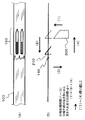
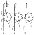
- FIG. 8 shows an example of a diagram using the rotary separating means 220, and the form of the separating means is not limited to this.
- FIG. 8 (A) shows a state in which, when the fiber bundle 100 is traveling along the fiber traveling direction B, the protruding portion 210 is inserted into the fiber bundle 100 and the fiber separation process is performed. In this state, the twisted portion 300 is not in contact with the protruding portion 210.
- a solid line 310 and a broken line 320 in FIG. 8A indicate single yarns in the fiber bundle 100, respectively. The positions of these single yarns 310 and 320 are switched with the twisted portion 300 as a boundary.
- the fiber bundle 100 When the fiber bundle 100 is run and the protruding portion 210 is brought into contact with the twisted portion 300 as it is, the fiber bundle is narrowed from C to D as shown in FIG. 8B.
- the reference numerals 310 and 320 are single yarns
- the present invention is not limited to this aspect, and the same applies to the case where the twisted portion 300 is formed in a fiber bundle state in which a certain amount of single yarns are collected.
- the image processing unit may further include an image calculation processing unit that calculates an image obtained by the imaging unit, and may further include a pressing force control unit that controls the pressing force of the separating unit 200 based on the calculation result of the image calculation processing unit.
- the image processing means detects a twist
- twist it is preferable to reduce it to a range of 0.01 to 0.8 times the upper limit of the pressing force. If it falls below this range, the pressing force cannot be substantially detected, making it difficult to control the pressing force or increasing the detection accuracy of the control device itself.
- the frequency which divides a twist increases, and a fiber bundle becomes thin.
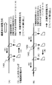
- FIG. 5 is an explanatory diagram showing an example of a movement cycle for inserting the rotary separating means.
- the rotary separating means 220 has a rotation mechanism provided with a rotation shaft 240 orthogonal to the longitudinal direction of the fiber bundle 100, and a protrusion 210 is provided on the surface of the rotation shaft 240.
- the protruding portion 210 provided in the rotary separating means 220 is pushed into the fiber bundle 100, and the fiber separation process starts. .
- the rotation separating means 220 has a pressing force detection mechanism and a rotation stop position holding mechanism. Until the predetermined pressing force is applied to the rotary separating means 220 by both mechanisms, the rotation stop position is maintained at the position shown in FIG.
- a predetermined pressing force is exceeded, such as when the entangled portion 160 is generated in the protruding portion 210, the rotating / separating means 220 starts to rotate as shown in FIG.
- FIG. 5C the protruding portion 210 (black circle) is removed from the fiber bundle 100, and the next protruding portion 210 (white circle) is inserted into the fiber bundle 100.
- FIGS. 5 (A) to 5 (C) the shorter the undivided fiber processing section. Therefore, when it is desired to increase the proportion of the fiber bundles in the fiber separation process section, FIG. 5 (A) to FIG. It is preferable to shorten the operation of FIG.
- a fiber bundle with a high fiber separation ratio is a fiber bundle in which the length of the fiber processed in the fiber bundle is increased, or a fiber with an increased frequency between the fiber processed and unfibered sections. It is a bunch.
- the number of the protrusions 210 provided is preferably 3 to 12 at an equal interval on the outer edge of the disk shape, and more preferably 4 to 8.
- the rotary splitting means 220 includes an imaging means for detecting twist. It is preferable to have. Specifically, at the normal time until the imaging means detects the twist, the rotating splitting means 220 performs the splitting process by intermittently repeating the rotation and stop, and when the twist is detected, The fiber bundle width can be stabilized by increasing the rotational speed of the fiber means 220 from the normal time and / or shortening the stop time.
- the stop time can be set to zero, that is, the motor can continue to rotate continuously without stopping.
- the rotation separating means 220 may always be continuously rotated. At that time, it is preferable that either one of the traveling speed of the fiber bundle 100 and the rotational speed of the rotary separating unit 220 be relatively faster or slower. When the speed is the same, since the operation of piercing / extracting the protruding portion 210 from / to the fiber bundle 100 is performed, the splitting treatment section can be formed, but the splitting action on the fiber bundle 100 is weak, so the splitting treatment is performed. It may not be done sufficiently.
- a reciprocating mechanism for performing insertion and extraction of the separating means 200 and the rotating separating means 220 by reciprocating movement of the separating means 200 and rotating separating means 220.
- a reciprocating mechanism for reciprocating the separating means 200 and the rotating separating means 220 along the feeding direction of the fiber bundle 100.
- a linear actuator such as compressed air or an electric cylinder or slider can be used.
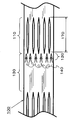
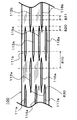
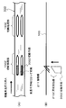
- FIG. 6 is a schematic two-dimensional plan view showing an example of a partially split fiber bundle obtained by subjecting a fiber bundle to splitting according to the present invention.
- the partial fiber splitting bundle in the present invention includes splitting processing sections 111a to 118a in which the fiber bundle 100 composed of a plurality of single yarns is partially split along the longitudinal direction of the fiber bundle, and adjacent splitting sections.
- the undivided fiber processing sections formed between the fiber processing sections are alternately formed.
- At least one end portion of at least one splitting treatment section is formed with an entanglement accumulating portion 830 in which entangled portions in which single yarns are entangled are accumulated. It is also preferable that As described above, the entanglement accumulation unit 830 forms (moves) the entanglement of single yarns that existed in advance in the fiber separation processing section on the contact portion 211 by the fiber separation unit 200, or the fiber separation unit. 200 is formed (manufactured) or the like when a new entangled single yarn is formed.
- the entanglement accumulation part 830 is formed at at least one end of at least one splitting processing section, but the single yarn constituting the fiber bundle 100 is formed.
- the plurality of separating means 200 is subjected to a separating process under the same operating conditions, and at least in the separating process section It is further preferable that an entanglement accumulating portion including an entangled portion in which the single yarn is entangled is formed at one end portion.
- the partial splitting fiber bundle according to the present invention can take various modes as long as the splitting processing section and the unsplit processing section are alternately formed.
- the plurality of splitting means 200 can be arranged in the width direction of the fiber bundle 100 and can be controlled independently, the splitting treatment section and the unsplit processing section that are alternately formed Are preferably provided in parallel to the width direction of the fiber bundle 100.
- the separation processing sections (111a to 111d, 112a to 112d, 113a to 113d) are arranged in parallel, or the separation processing is performed as shown in FIG. 7 (B).
- the sections 110a are alternately arranged, or the fiber separation sections 110b are randomly arranged as shown in FIG. 7C, and the phase is arbitrarily shifted with respect to the width direction of the fiber bundle 100.
- Processing sections can be arranged.
- FIG. 7 it is shown that the same number division processing sections (for example, 111 a and 111 b) in the code are processed by the same division means 200.
- the splitting treatment sections and the unsplit processing sections that are provided alternately in parallel with the width direction of the fiber bundle are at least one part in an arbitrary length in the longitudinal direction of the fiber bundle 100. It is preferable to have a fiber processing section. For example, as shown in FIG. 6, when an arbitrary length region 810 is taken as an example, at least the splitting processing sections 111b, 112a, 113a, 115a, 116a, and 118a are included.
- the arbitrary length region 810 and the arbitrary length region 820 include one end portion of any separation processing section in the region, but the present invention is not limited to such an aspect, and the arbitrary length region Like 821, the aspect in which only the center part of the parting process area 112b and 116b is contained may be sufficient.
- the number of the splitting treatment sections included in the arbitrary length region does not have to be constant, and the number of the splitting processing sections varies, for example, the partial splitting fiber bundle is set to a predetermined length in the subsequent process.
- a portion having a large number of fiber separation processing sections becomes a fiber separation start point, and can be easily controlled to be divided into fiber bundles having a predetermined number of single yarns.
- the molding time can be shortened, and voids and the like in the reinforcing fiber composite material can be reduced.
- the unsplit processing section is a split processing section (111b) that is newly split at a certain distance after finishing the split processing of one split processing section (example: 111a in FIG. 6).
- the present invention is not limited to this.
- the undivided fiber separation section is not formed in the section between the end portions of the fiber separation sections 113c and 113d with respect to the longitudinal direction of the fiber bundle. Even in such a case, if the splitting position is shifted with respect to the width direction of the fiber bundle 100 at the single yarn level, and different splitting processing sections are respectively formed, the length is limited in the longitudinal direction in the fiber bundle.
- the ends of the separation process section may be close to each other (substantially connected).
- the number of division processing sections when reinforcing fibers are used in the fiber bundle has at least (F / 10000-1) or more and less than (F / 50-1) division processing sections in a certain width direction region. It is preferable.
- F is the total number of single yarns (pieces) constituting the fiber bundle to be split.
- the number of splitting sections is at least (F / 10000-1) or more in a certain width direction area, so that the split fiber bundles are cut into a predetermined length to strengthen the discontinuous fibers.
- the end portion of the reinforcing fiber bundle in the discontinuous fiber reinforced composite material is finely divided, so that a discontinuous fiber reinforced composite material having excellent mechanical properties can be obtained.
- the molding time can be shortened, and voids and the like in the reinforcing fiber composite material can be reduced.
- the number of splitting treatment sections is less than (F / 50-1)
- the resulting partially split fiber bundle is less likely to break the yarn, and it is possible to suppress a decrease in mechanical properties when a fiber-reinforced composite material is obtained.
- the splitting treatment section is provided with periodicity and regularity in the longitudinal direction of the fiber bundle 100, when the partial splitting fiber bundle is a discontinuous fiber cut to a predetermined length in a subsequent step, It is possible to easily control the number of split fiber bundles.
- the fiber-reinforced resin molding material in the present invention includes a reinforcing fiber mat obtained by cutting and dispersing the above-described partially divided fiber bundle, and a matrix resin.
- the average fiber length of the cut partial fiber bundle according to the present invention is preferably in the range of 5 to 100 mm, and more preferably in the range of 10 to 80 mm.
- the fiber length distribution may be a single fiber length distribution or a mixture of two or more.
- the matrix resin is not particularly limited, and either a thermosetting resin or a thermoplastic resin can be used, and can be appropriately selected as long as the mechanical properties as a molded product are not greatly deteriorated.
- a thermosetting resin vinyl ester resin, epoxy resin, unsaturated polyester resin, phenol resin, epoxy acrylate resin, urethane acrylate resin, phenoxy resin, alkyd resin, urethane resin, maleimide resin, cyanate resin, etc.
- thermoplastic resins polyolefin resins such as polyethylene resin and polypropylene resin, polyamide resins such as nylon 6 resin and nylon 6,6 resin, polyester resins such as polyethylene terephthalate resin and polybutylene terephthalate resin, polyphenylene Resins such as sulfide resin, polyether ketone resin, polyether sulfone resin, and aromatic polyamide resin can be used.
- polyamide resin polyethylene resin and polypropylene resin
- polyamide resins such as nylon 6 resin and nylon 6,6 resin
- polyester resins such as polyethylene terephthalate resin and polybutylene terephthalate resin
- polyphenylene Resins such as sulfide resin, polyether ketone resin, polyether sulfone resin, and aromatic polyamide resin
- a thermosetting resin can be more preferably used from the viewpoint of impregnation of the matrix resin and applicability to the impregnation step.
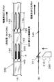
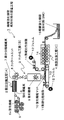
- FIG. 11 shows a method for manufacturing a fiber-reinforced resin molding material according to an embodiment of the present invention.
- 1 shows the whole manufacturing process of a fiber reinforced resin molding material containing at least a reinforcing fiber mat and a matrix resin in the present invention, and the manufacturing process 1 includes at least a reinforcing fiber composed of a plurality of single yarns.
- Partial splitting process [A] 2 for obtaining a partial split fiber bundle 7 formed by alternately forming a split processing section and an unsplit processing section split into a plurality of bundles along the longitudinal direction of the bundle Then, the partial fiber splitting bundle 7 is cut and dispersed to form a matting step [B] 3 to obtain the reinforcing fiber mat 10, and the reinforcing fiber mat 10 is coated with a matrix resin (in this embodiment, a thermosetting resin 11).
- a resin impregnation step [C] 4 to be impregnated is included.
- a reinforcing fiber bundle 6 composed of a plurality of single yarn reinforcing fibers 6a fed out from a plurality of creels 5 is supplied to the partial fiber separation process [A] 2, and the partial fiber separation process is performed in the process 2 as described above.
- the partial fiber split bundle 7 is produced.
- the partially split fiber bundle 7 thus produced is subsequently (continuously) supplied to the matting step [B] 3, and after being cut into discontinuous fiber bundles by the cutter unit 8 in that step 3.
- the reinforcing fiber mat 10 is sprayed through the spraying mechanism 9 on the belt 13 that is circulated, for example.
- the reinforcing fiber mat 10 is impregnated with a thermosetting resin 11 as a matrix resin.
- the reinforcing fiber mat 10 and the supplied thermosetting resin 11 to be impregnated are used as the reinforcing fiber mat 10.
- the resin impregnation in the resin impregnation step [C] 4 is accelerated by being sandwiched between the films 12 sequentially supplied to the upper and lower sides of the film and being pressed between the plurality of resin impregnation rollers 14 in the sandwiched state, for example. Yes.
- the reinforced fiber mat 10 impregnated with the matrix resin is folded or wound as shown in the figure as a continuous sheet-like fiber reinforced resin molding material 15 to form a series of continuous fiber reinforced resin moldings.
- the material manufacturing process 1 is completed.
- the fiber reinforced resin molding material 15 is manufactured as a sheet molding compound (SMC), for example.
- a partially split fiber bundle 7 is prepared, and the partially split fiber bundle 7 is cut and dispersed to prepare a reinforcing fiber mat 10 derived from the partially split fiber bundle, which is then impregnated with a matrix resin 11. Since the fiber reinforced resin molding material 15 is obtained, when the partially split fiber bundle 7 is cut / dispersed to form the reinforcing fiber mat 10 as an intermediate base material of the discontinuous fiber bundle, It is possible to mix fiber bundles and fiber bundles of thick bundles within the range of the optimum ratio, and in the fiber reinforced resin molding material 15 impregnated with the matrix resin 11, the fluidity during molding and the molding product It becomes possible to express the mechanical properties in a balanced manner.
- the fiber bundle in the production process of the partial fiber bundle 7, as described above, the fiber bundle can be continuously and stably slit, and the partial fiber bundle 7 having an optimum shape can be easily and efficiently manufactured.
- the fiber bundle containing a twist or a fiber bundle having a large number of single yarns of large tow it is possible to perform continuous slit processing without worrying about the replacement life of the rotary blade.
- inexpensive large tow continuous slitting can be performed, thereby making it possible to reduce the material cost and manufacturing cost of the final molded product.
- a series of processes is preferable as a preferable example from the viewpoint that a desired fiber reinforced resin molding material 15 can be manufactured efficiently and smoothly with excellent productivity.
- [A] to [C] are continuously performed in one process
- a series of steps [A] to [C] are not necessarily performed continuously in one process. After partially winding the partially split fiber bundle obtained through A], it may be subjected to step [B].
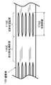
- the angle ⁇ ( It is also preferable to cut at 0 ⁇ ⁇ 90 °.
- the partial splitting is performed by the cutting blade 8a inclined at an angle ⁇ (0 ⁇ ⁇ 90 °) with respect to the longitudinal direction of the partially split fiber bundle 7 (the traveling direction of the fiber bundle in the figure).
- the fiber bundle 7 is cut.
- the cutting line by the cutting blade 8a has more opportunities to extend across the splitting processing unit 150 and the unsplit processing unit 181, and the partial split fiber bundle 7 is cut to obtain a fiber bundle of discontinuous fibers.
- Fiber bundle [A-1] A continuous carbon fiber bundle having a fiber diameter of 7 ⁇ m, a tensile elastic modulus of 230 GPa and a number of single yarns of 12,000 (Torayca (registered trademark) T700S-12K-50-E manufactured by Toray Industries, Inc.) was used.
- Fiber bundle [A-2] A continuous carbon fiber bundle (manufactured by ZOLTEK, “PANEX (registered trademark) 35”) having a fiber diameter of 7.2 ⁇ m, a tensile elastic modulus of 240 GPa, and a number of single yarns of 50,000 was used.
- Matrix resin [M-1] 100 parts by weight of vinyl ester resin (manufactured by Dow Chemical Co., Ltd., “Delaken (registered trademark) 790”), tert-butyl peroxybenzoate (manufactured by NOF Corporation, “Perbutyl (registered trademark) Z” as a curing agent ”)
- zinc stearate manufactured by Sakai Chemical Industry Co., Ltd., SZ
- Example 1 The fiber bundle [A-1] is unwound at a constant speed of 10 m / min using a winder, passed through a vibration widening roll that vibrates in the axial direction at 5 Hz, subjected to a widening process, and then passed through a 20 mm wide width regulating roll. Thus, a widened fiber bundle widened to 20 mm was obtained. With respect to the obtained widened fiber bundle, an iron plate for fiber separation processing having a protruding shape having a thickness of 0.2 mm, a width of 3 mm, and a height of 20 mm is arranged in parallel at equal intervals of 5 mm with respect to the width direction of the reinforcing fiber bundle.
- the set splitting treatment means was prepared. This splitting treatment means was intermittently inserted into and extracted from the widened fiber bundle and wound around a bobbin to obtain a partially split fiber bundle.
- the splitting processing means pierces the widening fiber bundle traveling at a constant speed of 10 m / min to stab the splitting processing means for 3 seconds to generate a splitting processing section, and pulls the splitting processing means for 0.2 sec. The piercing operation was repeated.
- the fiber bundle is split into four parts in the width direction in the splitting treatment section, and at least one end of at least one splitting processing section has a single yarn. It had an entanglement accumulation part formed by accumulating entangled entanglement parts.
- a partially split fiber bundle is made 1500 m, the yarn twisted in the fiber bundle passes through in the running direction when inserting / removing the splitting treatment means without causing any yarn breakage or winding. Separation processing could be performed with a width of
- the obtained partially split fiber bundle is continuously inserted into a rotary cutter, and the fiber bundle is cut into a fiber length of 25 mm and dispersed so as to be uniformly dispersed, whereby the fiber orientation is isotropic.
- a continuous fiber nonwoven fabric was obtained.
- the basis weight of the obtained discontinuous fiber nonwoven fabric was 1 kg / m 2 .
- the matrix resin [M-1] was uniformly applied to each of the two polypropylene release films using a doctor blade to prepare two resin sheets.
- the discontinuous fiber nonwoven fabric obtained above was sandwiched between these two resin sheets from above and below, and the nonwoven fabric was impregnated with a roller to obtain a sheet-like fiber reinforced resin molding material.
- the coating amount of the resin was adjusted at the stage of resin sheet preparation so that the reinforcing fiber weight content of the fiber reinforced resin molding material was 47%.
- the fiber reinforced resin molding material was shape
- Example 2 The fiber bundle [A-2] is unwound at a constant speed of 10 m / min using a winder, passed through a vibration widening roll that vibrates in the axial direction at 10 Hz, subjected to a widening process, and then passed through a width regulating roll having a width of 60 mm. Thus, a widened fiber bundle widened to 60 mm was obtained. Partial splitting using a splitting processing means in which an iron plate for splitting processing having a protruding shape is set in parallel to the width direction of the reinforcing fiber bundle at an equal interval of 3.5 mm with respect to the obtained widened fiber bundle Evaluation was performed in the same manner as in Example 1 except that a fiber bundle was produced.
- the obtained partly split fiber bundle is split into 17 parts in the width direction in the splitting process section, and at least one end of at least one splitting process section is It had an entanglement accumulation part in which the entanglement part where the yarn was entangled was accumulated.
- Table 1 shows a series of evaluation results obtained.
- Example 3 The widening fiber bundle using the fiber bundle [A-2] traveling at a constant speed of 10 m / min is stabbed with a 1 sec. Splitting treatment means to generate a splitting processing section, and the splitting processing means is pulled out during 1 sec. The evaluation was performed in the same manner as in Example 2 except that the piercing operation was repeated. Table 1 shows a series of evaluation results obtained.
- Example 4 The widening fiber bundle using the fiber bundle [A-2] traveling at a constant speed of 10 m / min is stabbed with a fiber separation processing means for 6 seconds to generate a fiber separation processing section, and the fiber separation processing means for 0.2 seconds.
- the evaluation was performed in the same manner as in Example 2 except that the operation of piercing and re-piercing was repeated. Table 1 shows a series of evaluation results obtained.
- Example 5 A widened fiber bundle using a fiber bundle [A-2] traveling at a constant speed of 10 m / min has a protruding shape with a thickness of 0.2 mm, a width of 3 mm, and a height of 20 mm, and has a contact surface with the fiber bundle.
- Example 6 Evaluation was performed in the same manner as in Example 2 except that the obtained partially separated fiber bundle was continuously inserted into a rotary cutter without being wound up, and subjected to a matting step and a resin impregnation step. .
- Table 1 shows a series of evaluation results obtained.
- Example 7 Evaluation was performed in the same manner as in Example 6 except that when the partially split fiber bundle was cut with a rotary cutter, the cutting angle was 15 ° with respect to the longitudinal direction of the fiber. Table 1 shows a series of evaluation results obtained.
- Example 1 Evaluation was carried out in the same manner as in Example 2 except that the fiber bundle [A-2] was cut and spread without being subjected to the widening / separation treatment to obtain a discontinuous fiber nonwoven fabric.
- Table 2 shows a series of evaluation results obtained.
- a widened fiber bundle using a fiber bundle [A-2] traveling at a constant speed of 10 m / min has a protruding shape with a thickness of 0.2 mm, a width of 3 mm, and a height of 20 mm, and has a contact surface with the fiber bundle.
- the severing processing means is set in a state where the severing processing iron plate processed in the shape of a blade is set in parallel at an equal interval of 3.5 mm with respect to the width direction of the reinforcing fiber bundle, and is continuously split.
- Example 7 For Examples 1 to 7, it was confirmed that both excellent mechanical properties (bending strength, elastic modulus) and low variation were exhibited at the same time. Particularly in Example 7, by setting the cutting angle ⁇ of the partially divided fiber bundle to 0 ° ⁇ ⁇ 90 °, the stress concentration at the end of the fiber bundle in the molded product and the formation of the resin rich portion are suppressed. It was possible to develop further high strength and low variation. Further, in this result, a clear method for confirming fluidity was not taken in, but all the flat plates molded for physical property evaluation had high surface smoothness, and there were no resin spots in which the resin was aggregated. In addition, the flat plate was completely filled with no chipping.
- the present invention can be applied to any fiber bundle that is desired to split a fiber bundle composed of a plurality of single yarns into two or more thin bundles.
- the obtained partially divided fiber bundle is impregnated with a matrix resin and can be used for any reinforcing fiber composite material.
Landscapes
- Engineering & Computer Science (AREA)
- Textile Engineering (AREA)
- Mechanical Engineering (AREA)
- Chemical & Material Sciences (AREA)
- Composite Materials (AREA)
- Reinforced Plastic Materials (AREA)
- Yarns And Mechanical Finishing Of Yarns Or Ropes (AREA)
- Treatment Of Fiber Materials (AREA)
- Moulding By Coating Moulds (AREA)
- Preliminary Treatment Of Fibers (AREA)
Abstract
Description
(1)複数の単糸からなる繊維束の長手方向に沿って、複数の束に分繊された分繊処理区間と未分繊処理区間とが交互に形成されてなる部分分繊繊維束であって、前記未分繊処理区間の含有率が3%以上50%以下であることを特徴とする部分分繊繊維束。
(2)前記分繊処理区間の長さが、30mm以上1500mm以下であることを特徴とする、(1)に記載の部分分繊繊維束。
(3)前記未分繊処理区間の長さが、1mm以上150mm以下であることを特徴とする、(1)または(2)に記載の部分分繊繊維束。
(4)前記分繊処理区間と前記未分繊処理区間の境界に絡合部および/または絡合集積部が形成されてなることを特徴とする、(1)~(3)のいずれかに記載の部分分繊繊維束。
(5)複数の単糸からなる繊維束を長手方向に沿って走行させながら、複数の突出部を具備する分繊手段を前記繊維束に突き入れて分繊処理部を生成するとともに、少なくとも1つの前記分繊処理部における前記突出部との接触部に前記単糸が交絡する絡合部を形成し、しかる後に前記分繊手段を前記繊維束から抜き取り、前記絡合部を含む絡合蓄積部を経過した後、再度前記分繊手段を前記繊維束に突き入れる部分分繊繊維束の製造方法であって、前記分繊手段を突き入れている分繊処理時間t1と、前記分繊手段を抜き取り、再度前記繊維束に突き入れるまでの時間t2が、下記式(1)を満たすことを特徴とする、部分分繊繊維束の製造方法。
0.03≦t2/(t1+t2)≦0.5 ・・・式(1)
(6)複数の単糸からなる繊維束に複数の突出部を具備する分繊手段を前記繊維束に突き入れ、前記分繊手段を前記繊維束の長手方向に沿って走行させながら分繊処理部を生成するとともに、少なくとも1つの前記分繊処理部における前記突出部との接触部に前記単糸が交絡する絡合部を形成し、しかる後に前記分繊手段を前記繊維束から抜き取り、前記絡合部を含む絡合蓄積部を経過する位置まで前記分繊手段を走行させた後、再度前記分繊手段を前記繊維束に突き入れる部分分繊繊維束の製造方法であって、前記分繊手段を突き入れている分繊処理時間t3と、前記分繊手段を抜き取り、再度前記繊維束に突き入れるまでの時間t4が、下記式(2)を満たすことを特徴とする、部分分繊繊維束の製造方法。
0.03≦t4/(t3+t4)≦0.5 ・・・式(2)
(7)前記接触部における前記突出部に作用する前記繊維束の幅あたりに作用する押圧力を検知し、前記押圧力の上昇に伴って前記繊維束から前記分繊手段を抜き取ることを特徴とする、(5)または(6)に記載の部分分繊繊維束の製造方法。
(8)前記繊維束に突き入れた前記分繊手段から前記繊維束の長手方向に沿って前後の少なくともいずれか一方の10~1000mmの範囲における前記繊維束の撚りの有無を撮像手段により検知することを特徴とする、(5)~(7)のいずれかに記載の部分分繊繊維束の製造方法。
(9)前記接触部における前記突出部に作用する前記繊維束の幅あたりに作用する押圧力を検知し、前記撮像手段により撚りを検知し、前記突出部が該撚りに接触する直前から通過するまで、前記押圧力が低減するように前記分繊手段を制御することを特徴とする、(8)に記載の部分分繊繊維束の製造方法。
(10)複数の前記突出部が、それぞれ独立して制御可能であることを特徴とする、(5)~(9)のいずれかに記載の部分分繊繊維束の製造方法。
(11)前記分繊手段が、前記繊維束の長手方向に直交する回転軸を備え、前記回転軸表面に前記突出部が設けられていることを特徴とする、(5)~(10)のいずれかに記載の部分分繊繊維束の製造方法。
(12)(1)~(4)のいずれかに記載の部分分繊繊維束を切断・散布して得られる強化繊維マットと、マトリックス樹脂を含む繊維強化樹脂成形材料。
(13)前記マトリックス樹脂が熱硬化性樹脂であることを特徴とする、(12)に記載の繊維強化樹脂成形材料。
(14)前記繊維強化樹脂成形材料がシートモールディングコンパウンドであることを特徴とする、(12)または(13)に記載の繊維強化樹脂成形材料。
(15)(12)~(14)のいずれかに記載の繊維強化樹脂成形材料の製造方法であって、少なくとも下記工程[A]~[C]を有することを特徴とする、繊維強化樹脂成形材料の製造方法。
[A]複数の単糸からなる強化繊維束の長手方向に沿って、複数の束に分繊された分繊処理部と未分繊処理部とを交互に形成してなる部分分繊繊維束を得る部分分繊工程。
[B]前記部分分繊繊維束を切断して散布し、強化繊維マットを得るマット化工程。
[C]前記強化繊維マットにマトリックス樹脂を含浸させる樹脂含浸工程。
(16)少なくとも前記工程[A]~[C]を1つのプロセス内で連続的に行うことを特徴とする、(15)に記載の繊維強化樹脂成形材料の製造方法。
(17)前記工程[B]においては、部分分繊繊維束をその長手方向に対して、角度θ(0<θ<90°)で切断することを特徴とする、(15)または(16)に記載の繊維強化樹脂成形材料の製造方法。
0.03≦t2/(t1+t2)≦0.5 ・・・式(1)
この場合、分繊手段200の移動方向は図の(1)~(4)の繰り返しとなる。
0.03≦t4/(t3+t4)≦0.5 ・・・式(2)
この場合にも、分繊手段200の移動方向は図の(1)~(4)の繰り返しとなる。
本発明における繊維強化樹脂成形材料は、上述の部分分繊繊維束を切断・散布して得られる強化繊維マットと、マトリックス樹脂を含むものである。
繊維束[A-1]:
繊維径7μm、引張弾性率230GPa、単糸数12,000本の連続した炭素繊維束(東レ(株)製、“トレカ(登録商標)”T700S-12K-50-E)を用いた。
繊維束[A-2]:
繊維径7.2μm、引張弾性率240GPa、単糸数50,000本の連続した炭素繊維束(ZOLTEK社製、“PANEX(登録商標)35”)を用いた。
ビニルエステル樹脂(ダウ・ケミカル(株)製、“デラケン(登録商標)790”)を100重量部、硬化剤としてtert-ブチルパーオキシベンゾエート(日本油脂(株)製、“パーブチル(登録商標)Z”)を1重両部、増粘剤として酸化マグネシウム(協和化学工業(株)製、MgO#40)を4重量部、内部離型剤としてステアリン酸亜鉛(堺化学工業(株)製、SZ-2000)を2重量部を、十分に混合・攪拌して得られた樹脂コンパウンドを用いた。
繊維強化樹脂成形材料を平板金型の中央部に配置(チャージ率にして50%)した後、加圧型プレス機により10MPaの加圧のもと、約140℃×5分間の条件により硬化させ、300×400mmの平板を得た。平板長手方向を0°とし、得られた平板より0°と90°方向から、それぞれ100×25×1.6mmの試験片を5片(合計10片)を切り出し、JIS K7074(1988年)に準拠し測定を実施した。力学特性としては、曲げ強度、曲げ弾性率、曲げ弾性率のCV値(%)を求めた(CV:変動係数)。
繊維束[A-1]を、ワインダーを用いて一定速度10m/minで巻出し、5Hzで軸方向へ振動する振動拡幅ロールに通し、拡幅処理を施した後に、20mm幅の幅規制ロールを通すことで20mmへ拡幅した拡幅繊維束を得た。得られた拡幅繊維束に対して、厚み0.2mm、幅3mm、高さ20mmの突出形状を具備する分繊処理用鉄製プレートを、強化繊維束の幅方向に対して5mm等間隔に並行にセットした分繊処理手段を準備した。この分繊処理手段を拡幅繊維束に対して、間欠式に抜き挿しし、ボビンに巻き取ることによって部分分繊繊維束を得た。
繊維束[A-2]を、ワインダーを用いて一定速度10m/minで巻出し、10Hzで軸方向へ振動する振動拡幅ロールに通し、拡幅処理を施した後に、60mm幅の幅規制ロールを通すことで60mmに拡幅した拡幅繊維束を得た。得られた拡幅繊維束に対して突出形状を具備する分繊処理用鉄製プレートを強化繊維束の幅方向に対して3.5mm等間隔に並行にセットした分繊処理手段を用いて部分分繊繊維束を作製した以外は実施例1と同様にして評価を行った。
一定速度10m/minで走行する繊維束[A-2]を用いた拡幅繊維束に対して、1sec間分繊処理手段を突き刺し分繊処理区間を生成し、1sec間で分繊処理手段を抜き、再度突き刺す動作を繰り返し行なった以外は、実施例2と同様にして評価を行った。得られた一連の評価結果は表1に示す。
一定速度10m/minで走行する繊維束[A-2]を用いた拡幅繊維束に対して、6sec間分繊処理手段を突き刺し分繊処理区間を生成し、0.2sec間で分繊処理手段を抜き、再度突き刺す動作を繰り返し行なった以外は、実施例2と同様にして評価を行った。得られた一連の評価結果は表1に示す。
一定速度10m/minで走行する繊維束[A-2]を用いた拡幅繊維束に対して、厚み0.2mm、幅3mm、高さ20mmの突出形状を具備し、繊維束との接触面を刃状に加工した分繊処理用鉄製プレートを強化繊維束の幅方向に対して3.5mm等間隔に並行にセットした分繊処理手段を用いて部分分繊繊維束を作製した以外は実施例2と同様にして評価を行った。得られた一連の評価結果は表1に示す。
得られた部分分繊繊維束を一旦巻き取ることなく、連続的にロータリーカッターへと挿入し、マット化工程、樹脂含浸工程へと供した以外は、実施例2と同様にして評価を行った。得られた一連の評価結果は表1に示す。
前記部分分繊繊維束をロータリーカッターで切断する際に、切断角度が繊維の長手方向に対して15°である以外は、実施例6と同様にして評価を行った。得られた一連の評価結果は表1に示す。
繊維束[A-2]に拡幅処理・分繊処理を施さずに切断、散布し、不連続繊維不織布を得た以外は、実施例2と同様にして評価を行った。得られた一連の評価結果は表2に示す。
一定速度10m/minで走行する繊維束[A-2]を用いた拡幅繊維束に対して、分繊処理手段を常に突き刺した状態で保持し、連続的に分繊処理を施した連続分繊繊維束を作製した。得られた連続分繊処理繊維束は分繊処理区間が繊維長手方向に連続して形成され、一部で著しい毛羽立ちによる品位悪化が見られ、繊維束内に存在した繊維の撚りが分繊処理手段に集積され、部分的な糸切れが生じ、連続して分繊処理を行うことが出来なかった。
一定速度10m/minで走行する繊維束[A-2]を用いた拡幅繊維束に対して、厚み0.2mm、幅3mm、高さ20mmの突出形状を具備し、繊維束との接触面を刃状に加工した分繊処理用鉄製プレートを強化繊維束の幅方向に対して3.5mm等間隔に並行にセットした分繊処理手段を常に突き刺した状態で保持し、連続的に分繊処理を施すことを試みたが、糸の撚りや糸道の振動やずれに起因して糸切れが頻発し、繊維束を巻き取るに至らなかった。


2 部分分繊工程[A]
3 マット化工程[B]
4 樹脂含浸工程[C]
5 クリール
6 強化繊維束
6a 強化繊維
7 部分分繊繊維束
8 カッターユニット
8a 切断刃
9 散布機構
10 強化繊維マット
11 熱硬化性樹脂
12 フィルム
13 ベルト
14 樹脂含浸ローラー
15 繊維強化樹脂成形材料
100 繊維束
110、110a、110b、111a、111b、111c、111d、112a、112b、113a、113b、113c、113d、114a、115a、116a、116b、117a、118a 分繊処理区間
110Z 切断処理区間
120、830 絡合蓄積部
130 未分繊処理区間
130Z 非切断処理区間
140 毛羽溜まり
150 分繊処理部
150Z 切断処理部
160 絡合部
170 分繊距離
170Z 切断距離
180 部分分繊繊維束
181 未分繊処理部
200 分繊手段
200Z 切断手段
210 突出部
210Z 刃状突出部
211 接触部
220 回転分繊手段
230L、230R 角部
240 回転軸
300 撚り部
310、320 繊維束に含まれる単糸
810、820、821 部分分繊繊維束の長手方向における任意長さ領域
Claims (17)
- 複数の単糸からなる繊維束の長手方向に沿って、複数の束に分繊された分繊処理区間と未分繊処理区間とが交互に形成されてなる部分分繊繊維束であって、前記未分繊処理区間の含有率が3%以上50%以下であることを特徴とする部分分繊繊維束。
- 前記分繊処理区間の長さが、30mm以上1500mm以下であることを特徴とする、請求項1に記載の部分分繊繊維束。
- 前記未分繊処理区間の長さが、1mm以上150mm以下であることを特徴とする、請求項1または2に記載の部分分繊繊維束。
- 前記分繊処理区間と前記未分繊処理区間の境界に絡合部および/または絡合集積部が形成されてなることを特徴とする、請求項1~3のいずれかに記載の部分分繊繊維束。
- 複数の単糸からなる繊維束を長手方向に沿って走行させながら、複数の突出部を具備する分繊手段を前記繊維束に突き入れて分繊処理部を生成するとともに、少なくとも1つの前記分繊処理部における前記突出部との接触部に前記単糸が交絡する絡合部を形成し、しかる後に前記分繊手段を前記繊維束から抜き取り、前記絡合部を含む絡合蓄積部を経過した後、再度前記分繊手段を前記繊維束に突き入れる部分分繊繊維束の製造方法であって、前記分繊手段を突き入れている分繊処理時間t1と、前記分繊手段を抜き取り、再度前記繊維束に突き入れるまでの時間t2が、下記式(1)を満たすことを特徴とする、部分分繊繊維束の製造方法。
0.03≦t2/(t1+t2)≦0.5 ・・・式(1) - 複数の単糸からなる繊維束に複数の突出部を具備する分繊手段を前記繊維束に突き入れ、前記分繊手段を前記繊維束の長手方向に沿って走行させながら分繊処理部を生成するとともに、少なくとも1つの前記分繊処理部における前記突出部との接触部に前記単糸が交絡する絡合部を形成し、しかる後に前記分繊手段を前記繊維束から抜き取り、前記絡合部を含む絡合蓄積部を経過する位置まで前記分繊手段を走行させた後、再度前記分繊手段を前記繊維束に突き入れる部分分繊繊維束の製造方法であって、前記分繊手段を突き入れている分繊処理時間t3と、前記分繊手段を抜き取り、再度前記繊維束に突き入れるまでの時間t4が、下記式(2)を満たすことを特徴とする、部分分繊繊維束の製造方法。
0.03≦t4/(t3+t4)≦0.5 ・・・式(2) - 前記接触部における前記突出部に作用する前記繊維束の幅あたりに作用する押圧力を検知し、前記押圧力の上昇に伴って前記繊維束から前記分繊手段を抜き取ることを特徴とする、請求項5または請求項6に記載の部分分繊繊維束の製造方法。
- 前記繊維束に突き入れた前記分繊手段から前記繊維束の長手方向に沿って前後の少なくともいずれか一方の10~1000mmの範囲における前記繊維束の撚りの有無を撮像手段により検知することを特徴とする、請求項5~7のいずれかに記載の部分分繊繊維束の製造方法。
- 前記接触部における前記突出部に作用する前記繊維束の幅あたりに作用する押圧力を検知し、前記撮像手段により撚りを検知し、前記突出部が該撚りに接触する直前から通過するまで、前記押圧力が低減するように前記分繊手段を制御することを特徴とする、請求項8に記載の部分分繊繊維束の製造方法。
- 複数の前記突出部が、それぞれ独立して制御可能であることを特徴とする、請求項5~9のいずれかに記載の部分分繊繊維束の製造方法。
- 前記分繊手段が、前記繊維束の長手方向に直交する回転軸を備え、前記回転軸表面に前記突出部が設けられていることを特徴とする、請求項5~10のいずれかに記載の部分分繊繊維束の製造方法。
- 請求項1~4のいずれかに記載の部分分繊繊維束を切断・散布して得られる強化繊維マットと、マトリックス樹脂を含む繊維強化樹脂成形材料。
- 前記マトリックス樹脂が熱硬化性樹脂であることを特徴とする、請求項12に記載の繊維強化樹脂成形材料。
- 前記繊維強化樹脂成形材料がシートモールディングコンパウンドであることを特徴とする、請求項12または13に記載の繊維強化樹脂成形材料。
- 請求項12~14のいずれかに記載の繊維強化樹脂成形材料の製造方法であって、少なくとも下記工程[A]~[C]を有することを特徴とする、繊維強化樹脂成形材料の製造方法。
[A]複数の単糸からなる強化繊維束の長手方向に沿って、複数の束に分繊された分繊処理部と未分繊処理部とを交互に形成してなる部分分繊繊維束を得る部分分繊工程。
[B]前記部分分繊繊維束を切断して散布し、強化繊維マットを得るマット化工程。
[C]前記強化繊維マットにマトリックス樹脂を含浸させる樹脂含浸工程。 - 少なくとも前記工程[A]~[C]を1つのプロセス内で連続的に行うことを特徴とする、請求項15に記載の繊維強化樹脂成形材料の製造方法。
- 前記工程[B]においては、部分分繊繊維束をその長手方向に対して、角度θ(0<θ<90°)で切断することを特徴とする、請求項15または16に記載の繊維強化樹脂成形材料の製造方法。
Priority Applications (9)
| Application Number | Priority Date | Filing Date | Title |
|---|---|---|---|
| CA3024095A CA3024095A1 (en) | 2016-06-20 | 2017-06-01 | Partially separated fiber bundle, production method for partially separated fiber bundle, fiber-reinforced resin molding material using partially separated fiber bundle, and production method for fiber-reinforced resin molding material using partially separated fiber bundle |
| EP17815124.7A EP3473757B1 (en) | 2016-06-20 | 2017-06-01 | Production method for partially separated fiber bundle |
| MX2018013771A MX389144B (es) | 2016-06-20 | 2017-06-01 | Haz de fibras parcialmente separado, metodo de produccion para haz de fibras parcialmente separado, material de moldeo de resina reforzado con fibra que usa haz de fibras parcialmente separado y metodo de produccion para material de moldeo de resina reforzado con fibra que usa haz de fibras parcialmente separado. |
| CN201780035763.1A CN109312502B (zh) | 2016-06-20 | 2017-06-01 | 部分分纤纤维束的制造方法、以及纤维增强树脂成型材料的制造方法 |
| ES17815124T ES2858748T3 (es) | 2016-06-20 | 2017-06-01 | Método de producción de haz de fibras parcialmente separado |
| JP2017535843A JP7001995B2 (ja) | 2016-06-20 | 2017-06-01 | 部分分繊繊維束とその製造方法、および部分分繊繊維束を用いた繊維強化樹脂成形材料とその製造方法 |
| KR1020187037900A KR102253272B1 (ko) | 2016-06-20 | 2017-06-01 | 부분 분섬 섬유 다발과 그의 제조 방법, 및 부분 분섬 섬유 다발을 사용한 섬유 강화 수지 성형 재료와 그의 제조 방법 |
| US16/309,391 US20190161890A1 (en) | 2016-06-20 | 2017-06-01 | Partially separated fiber bundle, production method of partially separated fiber bundle, fiber-reinforced resin molding material using partially separated fiber bundle, and production method of fiber-reinforced resin molding material using partially separated fiber bundle |
| US17/130,976 US11492731B2 (en) | 2016-06-20 | 2020-12-22 | Partially separated fiber bundle, production method of partially separated fiber bundle, fiber-reinforced resin molding material using partially separated fiber bundle, and production method of fiber-reinforced resin molding material using partially separated fiber bundle |
Applications Claiming Priority (6)
| Application Number | Priority Date | Filing Date | Title |
|---|---|---|---|
| JP2016-121902 | 2016-06-20 | ||
| JP2016-121903 | 2016-06-20 | ||
| JP2016121902 | 2016-06-20 | ||
| JP2016121903 | 2016-06-20 | ||
| JP2016123438 | 2016-06-22 | ||
| JP2016-123438 | 2016-06-22 |
Related Child Applications (2)
| Application Number | Title | Priority Date | Filing Date |
|---|---|---|---|
| US16/309,391 A-371-Of-International US20190161890A1 (en) | 2016-06-20 | 2017-06-01 | Partially separated fiber bundle, production method of partially separated fiber bundle, fiber-reinforced resin molding material using partially separated fiber bundle, and production method of fiber-reinforced resin molding material using partially separated fiber bundle |
| US17/130,976 Division US11492731B2 (en) | 2016-06-20 | 2020-12-22 | Partially separated fiber bundle, production method of partially separated fiber bundle, fiber-reinforced resin molding material using partially separated fiber bundle, and production method of fiber-reinforced resin molding material using partially separated fiber bundle |
Publications (1)
| Publication Number | Publication Date |
|---|---|
| WO2017221655A1 true WO2017221655A1 (ja) | 2017-12-28 |
Family
ID=60784059
Family Applications (1)
| Application Number | Title | Priority Date | Filing Date |
|---|---|---|---|
| PCT/JP2017/020403 Ceased WO2017221655A1 (ja) | 2016-06-20 | 2017-06-01 | 部分分繊繊維束とその製造方法、および部分分繊繊維束を用いた繊維強化樹脂成形材料とその製造方法 |
Country Status (11)
| Country | Link |
|---|---|
| US (2) | US20190161890A1 (ja) |
| EP (1) | EP3473757B1 (ja) |
| JP (1) | JP7001995B2 (ja) |
| KR (1) | KR102253272B1 (ja) |
| CN (1) | CN109312502B (ja) |
| CA (1) | CA3024095A1 (ja) |
| ES (1) | ES2858748T3 (ja) |
| HU (1) | HUE054136T2 (ja) |
| MX (1) | MX389144B (ja) |
| TW (1) | TW201835402A (ja) |
| WO (1) | WO2017221655A1 (ja) |
Cited By (10)
| Publication number | Priority date | Publication date | Assignee | Title |
|---|---|---|---|---|
| JP2019119148A (ja) * | 2018-01-09 | 2019-07-22 | ジャパンコンポジット株式会社 | シートモールディングコンパウンドの製造装置 |
| WO2019194090A1 (ja) * | 2018-04-04 | 2019-10-10 | 三菱ケミカル株式会社 | 繊維強化樹脂成形材料の製造方法及び繊維強化樹脂成形材料の製造装置 |
| WO2020066275A1 (ja) * | 2018-09-28 | 2020-04-02 | 東レ株式会社 | 部分分繊繊維束およびその製造方法 |
| WO2020090488A1 (ja) * | 2018-10-31 | 2020-05-07 | 東レ株式会社 | 繊維強化樹脂材料およびその製造方法 |
| JPWO2020195756A1 (ja) * | 2019-03-27 | 2020-10-01 | ||
| WO2021149578A1 (ja) | 2020-01-21 | 2021-07-29 | 三菱ケミカル株式会社 | Smcの製造方法 |
| WO2021187346A1 (ja) | 2020-03-18 | 2021-09-23 | 三菱ケミカル株式会社 | Smcの製造方法 |
| WO2021193234A1 (ja) | 2020-03-26 | 2021-09-30 | 三菱ケミカル株式会社 | Smcの製造方法 |
| US11518116B2 (en) | 2015-07-07 | 2022-12-06 | Mitsubishi Chemical Corporation | Method and apparatus for producing fiber-reinforced resin molding material |
| WO2024090144A1 (ja) | 2022-10-28 | 2024-05-02 | 三菱ケミカル株式会社 | 部分分割炭素繊維束を製造する方法 |
Families Citing this family (3)
| Publication number | Priority date | Publication date | Assignee | Title |
|---|---|---|---|---|
| EP3473759B1 (en) * | 2016-06-21 | 2023-04-05 | Toray Industries, Inc. | Partially separated fiber bundle, production method for partially separated fiber bundle, fiber-reinforced resin molding material using partially separated fiber bundle, and production method for fiber-reinforced resin molding material using partially separated fiber bundle |
| CN111070720B (zh) * | 2019-12-31 | 2021-12-17 | 中国人民解放军国防科技大学 | 一种纤维增强复合材料纤维位置控制装置和方法 |
| TWI855924B (zh) * | 2023-11-20 | 2024-09-11 | 明安國際企業股份有限公司 | 纖維預浸材之連續穿刺設備及穿刺方法 |
Citations (6)
| Publication number | Priority date | Publication date | Assignee | Title |
|---|---|---|---|---|
| JP2006219780A (ja) * | 2005-02-10 | 2006-08-24 | Toray Ind Inc | 炭素繊維の分割方法 |
| JP2011241494A (ja) * | 2010-05-17 | 2011-12-01 | Toyota Motor Corp | 開繊シートの製造装置及びその製造方法 |
| WO2016043037A1 (ja) * | 2014-09-17 | 2016-03-24 | 東レ株式会社 | 繊維強化樹脂成形材料 |
| WO2016104154A1 (ja) * | 2014-12-26 | 2016-06-30 | 東レ株式会社 | 部分分繊繊維束の製造方法および製造装置、部分分繊繊維束 |
| WO2016136812A1 (ja) * | 2015-02-26 | 2016-09-01 | 帝人株式会社 | 補強繊維ストランド分繊糸の製造方法 |
| WO2017006989A1 (ja) * | 2015-07-07 | 2017-01-12 | 三菱レイヨン株式会社 | 繊維強化樹脂成形材料の製造方法及び製造装置 |
Family Cites Families (17)
| Publication number | Priority date | Publication date | Assignee | Title |
|---|---|---|---|---|
| US2687356A (en) | 1948-08-04 | 1954-08-24 | Sealady Seafood Corp | Method of curing and processing fish |
| US3208125A (en) * | 1963-07-17 | 1965-09-28 | Bancroft & Sons Co J | Apparatus for making bulked yarn |
| CH557814A (de) | 1971-07-23 | 1975-01-15 | Givaudan & Cie Sa | Verfahren zur herstellung von neuen geschmackstoffen. |
| JP2002255448A (ja) | 2001-03-05 | 2002-09-11 | Mitsubishi Rayon Co Ltd | 複数炭素繊維束巻取体、この複数炭素繊維束巻取体から各炭素繊維束を分割する装置及び方法 |
| US6796115B1 (en) | 2001-12-19 | 2004-09-28 | Gilbert Patrick | Needle punched yarns |
| JP4192041B2 (ja) | 2002-07-15 | 2008-12-03 | 三菱レイヨン株式会社 | 炭素繊維前駆体繊維束の製造方法及び製造装置 |
| JP2005015953A (ja) | 2003-06-26 | 2005-01-20 | Mitsubishi Rayon Co Ltd | ガラス繊維集束剤用エマルション、ガラス繊維集束剤、ガラス繊維束、樹脂組成物、シートモールディングコンパウンド、バルクモールディングコンパウンド、並びに樹脂成形品及びその製造方法 |
| JP5572947B2 (ja) * | 2007-06-04 | 2014-08-20 | 東レ株式会社 | 成形材料、および、繊維強化プラスチック、ならびに、これらの製造方法 |
| JP2009114612A (ja) | 2007-10-16 | 2009-05-28 | Toray Ind Inc | チョップド繊維束および成形材料の製造方法、成形材料、繊維強化プラスチック |
| RU2527703C1 (ru) | 2011-02-01 | 2014-09-10 | Тейдзин Лимитед | Холст с хаотической ориентацией волокон и композитный материал, армированный волокном |
| US20120213997A1 (en) | 2011-02-21 | 2012-08-23 | United States Council For Automotive Research | Fiber tow treatment apparatus and system |
| JP5722732B2 (ja) | 2011-08-31 | 2015-05-27 | 帝人株式会社 | 熱可塑性複合材料形成用等方性ランダムマットの製造方法 |
| EP2687356A1 (en) | 2012-07-20 | 2014-01-22 | Ahlstrom Corporation | A unidirectional reinforcement and a method of producing a unidirectional reinforcement |
| US10738168B2 (en) | 2012-08-01 | 2020-08-11 | Teijin Limited | Random mat and fiber-reinforced composite material shaped product |
| JP5996320B2 (ja) | 2012-08-01 | 2016-09-21 | 帝人株式会社 | ランダムマットの製造方法 |
| WO2017159263A1 (ja) * | 2016-03-15 | 2017-09-21 | 東レ株式会社 | 繊維強化樹脂成形材料およびその製造方法 |
| JP7166937B2 (ja) * | 2019-01-09 | 2022-11-08 | 株式会社三共 | スロットマシン |
-
2017
- 2017-06-01 EP EP17815124.7A patent/EP3473757B1/en active Active
- 2017-06-01 MX MX2018013771A patent/MX389144B/es unknown
- 2017-06-01 ES ES17815124T patent/ES2858748T3/es active Active
- 2017-06-01 JP JP2017535843A patent/JP7001995B2/ja active Active
- 2017-06-01 KR KR1020187037900A patent/KR102253272B1/ko active Active
- 2017-06-01 CN CN201780035763.1A patent/CN109312502B/zh active Active
- 2017-06-01 WO PCT/JP2017/020403 patent/WO2017221655A1/ja not_active Ceased
- 2017-06-01 US US16/309,391 patent/US20190161890A1/en not_active Abandoned
- 2017-06-01 HU HUE17815124A patent/HUE054136T2/hu unknown
- 2017-06-01 CA CA3024095A patent/CA3024095A1/en not_active Abandoned
- 2017-06-19 TW TW106120295A patent/TW201835402A/zh unknown
-
2020
- 2020-12-22 US US17/130,976 patent/US11492731B2/en active Active
Patent Citations (6)
| Publication number | Priority date | Publication date | Assignee | Title |
|---|---|---|---|---|
| JP2006219780A (ja) * | 2005-02-10 | 2006-08-24 | Toray Ind Inc | 炭素繊維の分割方法 |
| JP2011241494A (ja) * | 2010-05-17 | 2011-12-01 | Toyota Motor Corp | 開繊シートの製造装置及びその製造方法 |
| WO2016043037A1 (ja) * | 2014-09-17 | 2016-03-24 | 東レ株式会社 | 繊維強化樹脂成形材料 |
| WO2016104154A1 (ja) * | 2014-12-26 | 2016-06-30 | 東レ株式会社 | 部分分繊繊維束の製造方法および製造装置、部分分繊繊維束 |
| WO2016136812A1 (ja) * | 2015-02-26 | 2016-09-01 | 帝人株式会社 | 補強繊維ストランド分繊糸の製造方法 |
| WO2017006989A1 (ja) * | 2015-07-07 | 2017-01-12 | 三菱レイヨン株式会社 | 繊維強化樹脂成形材料の製造方法及び製造装置 |
Non-Patent Citations (1)
| Title |
|---|
| See also references of EP3473757A4 * |
Cited By (33)
| Publication number | Priority date | Publication date | Assignee | Title |
|---|---|---|---|---|
| US11919255B2 (en) | 2015-07-07 | 2024-03-05 | Mitsubishi Chemical Corporation | Method and apparatus for producing fiber-reinforced resin molding material |
| US11518116B2 (en) | 2015-07-07 | 2022-12-06 | Mitsubishi Chemical Corporation | Method and apparatus for producing fiber-reinforced resin molding material |
| JP2019119148A (ja) * | 2018-01-09 | 2019-07-22 | ジャパンコンポジット株式会社 | シートモールディングコンパウンドの製造装置 |
| JP7085844B2 (ja) | 2018-01-09 | 2022-06-17 | ジャパンコンポジット株式会社 | シートモールディングコンパウンドの製造装置 |
| JP2021178510A (ja) * | 2018-04-04 | 2021-11-18 | 三菱ケミカル株式会社 | 繊維強化樹脂成形材料の製造方法及び繊維強化樹脂成形材料の製造装置 |
| WO2019194090A1 (ja) * | 2018-04-04 | 2019-10-10 | 三菱ケミカル株式会社 | 繊維強化樹脂成形材料の製造方法及び繊維強化樹脂成形材料の製造装置 |
| US12023876B2 (en) | 2018-04-04 | 2024-07-02 | Mitsubishi Chemical Corporation | Method for producing fiber-reinforced resin molding material, and apparatus for producing fiber-reinforced resin molding material |
| JPWO2019194090A1 (ja) * | 2018-04-04 | 2020-04-30 | 三菱ケミカル株式会社 | 繊維強化樹脂成形材料の製造方法及び繊維強化樹脂成形材料の製造装置 |
| JP2020114934A (ja) * | 2018-04-04 | 2020-07-30 | 三菱ケミカル株式会社 | 繊維強化樹脂成形材料の製造方法及び繊維強化樹脂成形材料の製造装置 |
| CN111936281A (zh) * | 2018-04-04 | 2020-11-13 | 三菱化学株式会社 | 纤维增强树脂成型材料的制造方法和纤维增强树脂成型材料的制造装置 |
| CN111936281B (zh) * | 2018-04-04 | 2022-04-29 | 三菱化学株式会社 | 纤维增强树脂成型材料的制造方法和纤维增强树脂成型材料的制造装置 |
| CN112639188A (zh) * | 2018-09-28 | 2021-04-09 | 东丽株式会社 | 部分分纤纤维束及其制造方法 |
| CN112639188B (zh) * | 2018-09-28 | 2022-11-08 | 东丽株式会社 | 部分分纤纤维束及其制造方法 |
| WO2020066275A1 (ja) * | 2018-09-28 | 2020-04-02 | 東レ株式会社 | 部分分繊繊維束およびその製造方法 |
| US11845629B2 (en) | 2018-09-28 | 2023-12-19 | Toray Industries, Inc. | Partially separated fiber bundle and method of manufacturing same |
| US11873376B2 (en) | 2018-10-31 | 2024-01-16 | Toray Industries, Inc. | Fiber-reinforced resin material and production method therefor |
| JP7329193B2 (ja) | 2018-10-31 | 2023-08-18 | 東レ株式会社 | 繊維強化樹脂材料およびその製造方法 |
| JPWO2020090488A1 (ja) * | 2018-10-31 | 2021-10-07 | 東レ株式会社 | 繊維強化樹脂材料およびその製造方法 |
| WO2020090488A1 (ja) * | 2018-10-31 | 2020-05-07 | 東レ株式会社 | 繊維強化樹脂材料およびその製造方法 |
| JPWO2020195756A1 (ja) * | 2019-03-27 | 2020-10-01 | ||
| US11794419B2 (en) | 2019-03-27 | 2023-10-24 | Toray Industries, Inc. | Fiber-reinforced resin molding material molded product and method of producing same |
| EP3950283A4 (en) * | 2019-03-27 | 2022-12-21 | Toray Industries, Inc. | FIBER REINFORCED RESIN MOLDING MATERIAL MOLDING PRODUCT AND METHOD OF MANUFACTURE THEREOF |
| JP7400807B2 (ja) | 2019-03-27 | 2023-12-19 | 東レ株式会社 | 繊維強化樹脂成形材料成形品およびその製造方法 |
| EP4292802A2 (en) | 2020-01-21 | 2023-12-20 | Mitsubishi Chemical Corporation | Smc manufacturing method |
| JPWO2021149578A1 (ja) * | 2020-01-21 | 2021-07-29 | ||
| WO2021149578A1 (ja) | 2020-01-21 | 2021-07-29 | 三菱ケミカル株式会社 | Smcの製造方法 |
| CN114981054A (zh) * | 2020-01-21 | 2022-08-30 | 三菱化学株式会社 | Smc的制造方法 |
| JP7115648B2 (ja) | 2020-01-21 | 2022-08-09 | 三菱ケミカル株式会社 | Smcの製造方法 |
| US12179388B2 (en) | 2020-01-21 | 2024-12-31 | Mitsubishi Chemical Corporation | SMC manufacturing method |
| WO2021187346A1 (ja) | 2020-03-18 | 2021-09-23 | 三菱ケミカル株式会社 | Smcの製造方法 |
| WO2021193234A1 (ja) | 2020-03-26 | 2021-09-30 | 三菱ケミカル株式会社 | Smcの製造方法 |
| US12319017B2 (en) | 2020-03-26 | 2025-06-03 | Mitsubishi Chemical Corporation | Method for manufacturing SMC |
| WO2024090144A1 (ja) | 2022-10-28 | 2024-05-02 | 三菱ケミカル株式会社 | 部分分割炭素繊維束を製造する方法 |
Also Published As
| Publication number | Publication date |
|---|---|
| ES2858748T3 (es) | 2021-09-30 |
| US20190161890A1 (en) | 2019-05-30 |
| EP3473757A4 (en) | 2019-07-17 |
| TW201835402A (zh) | 2018-10-01 |
| HUE054136T2 (hu) | 2021-08-30 |
| CN109312502A (zh) | 2019-02-05 |
| CN109312502B (zh) | 2021-10-29 |
| MX2018013771A (es) | 2019-03-28 |
| KR20190016977A (ko) | 2019-02-19 |
| CA3024095A1 (en) | 2017-12-28 |
| US20210108342A1 (en) | 2021-04-15 |
| KR102253272B1 (ko) | 2021-05-20 |
| EP3473757A1 (en) | 2019-04-24 |
| MX389144B (es) | 2025-03-20 |
| JP7001995B2 (ja) | 2022-01-20 |
| US11492731B2 (en) | 2022-11-08 |
| JPWO2017221655A1 (ja) | 2019-04-11 |
| EP3473757B1 (en) | 2021-02-17 |
Similar Documents
| Publication | Publication Date | Title |
|---|---|---|
| JP7001995B2 (ja) | 部分分繊繊維束とその製造方法、および部分分繊繊維束を用いた繊維強化樹脂成形材料とその製造方法 | |
| WO2017221657A1 (ja) | 部分分繊繊維束とその製造方法、および部分分繊繊維束を用いた繊維強化樹脂成形材料とその製造方法 | |
| JP6447518B2 (ja) | 部分分繊繊維束の製造方法および製造装置 | |
| WO2017221688A1 (ja) | 分繊繊維束の製造方法と分繊繊維束、および分繊繊維束を用いた繊維強化樹脂成形材料とその製造方法 | |
| JP7001996B2 (ja) | 部分分繊繊維束とその製造方法、および部分分繊繊維束を用いた繊維強化樹脂成形材料とその製造方法 | |
| JP7001998B2 (ja) | 部分分繊繊維束の製造方法と部分分繊繊維束、および部分分繊繊維束を用いた繊維強化樹脂成形材料とその製造方法 |
Legal Events
| Date | Code | Title | Description |
|---|---|---|---|
| ENP | Entry into the national phase |
Ref document number: 2017535843 Country of ref document: JP Kind code of ref document: A |
|
| ENP | Entry into the national phase |
Ref document number: 3024095 Country of ref document: CA |
|
| 121 | Ep: the epo has been informed by wipo that ep was designated in this application |
Ref document number: 17815124 Country of ref document: EP Kind code of ref document: A1 |
|
| NENP | Non-entry into the national phase |
Ref country code: DE |
|
| ENP | Entry into the national phase |
Ref document number: 20187037900 Country of ref document: KR Kind code of ref document: A |
|
| ENP | Entry into the national phase |
Ref document number: 2017815124 Country of ref document: EP Effective date: 20190121 |