WO2017221814A1 - 輸送用冷凍ユニット - Google Patents
輸送用冷凍ユニット Download PDFInfo
- Publication number
- WO2017221814A1 WO2017221814A1 PCT/JP2017/022224 JP2017022224W WO2017221814A1 WO 2017221814 A1 WO2017221814 A1 WO 2017221814A1 JP 2017022224 W JP2017022224 W JP 2017022224W WO 2017221814 A1 WO2017221814 A1 WO 2017221814A1
- Authority
- WO
- WIPO (PCT)
- Prior art keywords
- air guide
- air
- control box
- condenser
- refrigeration unit
- Prior art date
- Legal status (The legal status is an assumption and is not a legal conclusion. Google has not performed a legal analysis and makes no representation as to the accuracy of the status listed.)
- Ceased
Links
Images

Classifications
-
- F—MECHANICAL ENGINEERING; LIGHTING; HEATING; WEAPONS; BLASTING
- F25—REFRIGERATION OR COOLING; COMBINED HEATING AND REFRIGERATION SYSTEMS; HEAT PUMP SYSTEMS; MANUFACTURE OR STORAGE OF ICE; LIQUEFACTION SOLIDIFICATION OF GASES
- F25B—REFRIGERATION MACHINES, PLANTS OR SYSTEMS; COMBINED HEATING AND REFRIGERATION SYSTEMS; HEAT PUMP SYSTEMS
- F25B31/00—Compressor arrangements
- F25B31/006—Cooling of compressor or motor
-
- B—PERFORMING OPERATIONS; TRANSPORTING
- B60—VEHICLES IN GENERAL
- B60H—ARRANGEMENTS OF HEATING, COOLING, VENTILATING OR OTHER AIR-TREATING DEVICES SPECIALLY ADAPTED FOR PASSENGER OR GOODS SPACES OF VEHICLES
- B60H1/00—Heating, cooling or ventilating devices
- B60H1/00271—HVAC devices specially adapted for particular vehicle parts or components and being connected to the vehicle HVAC unit
-
- B—PERFORMING OPERATIONS; TRANSPORTING
- B60—VEHICLES IN GENERAL
- B60H—ARRANGEMENTS OF HEATING, COOLING, VENTILATING OR OTHER AIR-TREATING DEVICES SPECIALLY ADAPTED FOR PASSENGER OR GOODS SPACES OF VEHICLES
- B60H1/00—Heating, cooling or ventilating devices
- B60H1/32—Cooling devices
- B60H1/3204—Cooling devices using compression
- B60H1/3227—Cooling devices using compression characterised by the arrangement or the type of heat exchanger, e.g. condenser, evaporator
-
- B—PERFORMING OPERATIONS; TRANSPORTING
- B60—VEHICLES IN GENERAL
- B60H—ARRANGEMENTS OF HEATING, COOLING, VENTILATING OR OTHER AIR-TREATING DEVICES SPECIALLY ADAPTED FOR PASSENGER OR GOODS SPACES OF VEHICLES
- B60H1/00—Heating, cooling or ventilating devices
- B60H1/32—Cooling devices
- B60H1/3204—Cooling devices using compression
- B60H1/3232—Cooling devices using compression particularly adapted for load transporting vehicles
-
- F—MECHANICAL ENGINEERING; LIGHTING; HEATING; WEAPONS; BLASTING
- F25—REFRIGERATION OR COOLING; COMBINED HEATING AND REFRIGERATION SYSTEMS; HEAT PUMP SYSTEMS; MANUFACTURE OR STORAGE OF ICE; LIQUEFACTION SOLIDIFICATION OF GASES
- F25D—REFRIGERATORS; COLD ROOMS; ICE-BOXES; COOLING OR FREEZING APPARATUS NOT OTHERWISE PROVIDED FOR
- F25D11/00—Self-contained movable devices, e.g. domestic refrigerators
-
- F—MECHANICAL ENGINEERING; LIGHTING; HEATING; WEAPONS; BLASTING
- F25—REFRIGERATION OR COOLING; COMBINED HEATING AND REFRIGERATION SYSTEMS; HEAT PUMP SYSTEMS; MANUFACTURE OR STORAGE OF ICE; LIQUEFACTION SOLIDIFICATION OF GASES
- F25D—REFRIGERATORS; COLD ROOMS; ICE-BOXES; COOLING OR FREEZING APPARATUS NOT OTHERWISE PROVIDED FOR
- F25D11/00—Self-contained movable devices, e.g. domestic refrigerators
- F25D11/003—Transport containers
-
- F—MECHANICAL ENGINEERING; LIGHTING; HEATING; WEAPONS; BLASTING
- F25—REFRIGERATION OR COOLING; COMBINED HEATING AND REFRIGERATION SYSTEMS; HEAT PUMP SYSTEMS; MANUFACTURE OR STORAGE OF ICE; LIQUEFACTION SOLIDIFICATION OF GASES
- F25D—REFRIGERATORS; COLD ROOMS; ICE-BOXES; COOLING OR FREEZING APPARATUS NOT OTHERWISE PROVIDED FOR
- F25D19/00—Arrangement or mounting of refrigeration units with respect to devices or objects to be refrigerated, e.g. infrared detectors
-
- F—MECHANICAL ENGINEERING; LIGHTING; HEATING; WEAPONS; BLASTING
- F25—REFRIGERATION OR COOLING; COMBINED HEATING AND REFRIGERATION SYSTEMS; HEAT PUMP SYSTEMS; MANUFACTURE OR STORAGE OF ICE; LIQUEFACTION SOLIDIFICATION OF GASES
- F25D—REFRIGERATORS; COLD ROOMS; ICE-BOXES; COOLING OR FREEZING APPARATUS NOT OTHERWISE PROVIDED FOR
- F25D23/00—General constructional features
- F25D23/003—General constructional features for cooling refrigerating machinery
-
- H—ELECTRICITY
- H05—ELECTRIC TECHNIQUES NOT OTHERWISE PROVIDED FOR
- H05K—PRINTED CIRCUITS; CASINGS OR CONSTRUCTIONAL DETAILS OF ELECTRIC APPARATUS; MANUFACTURE OF ASSEMBLAGES OF ELECTRICAL COMPONENTS
- H05K7/00—Constructional details common to different types of electric apparatus
- H05K7/20—Modifications to facilitate cooling, ventilating, or heating
-
- H—ELECTRICITY
- H10—SEMICONDUCTOR DEVICES; ELECTRIC SOLID-STATE DEVICES NOT OTHERWISE PROVIDED FOR
- H10W—GENERIC PACKAGES, INTERCONNECTIONS, CONNECTORS OR OTHER CONSTRUCTIONAL DETAILS OF DEVICES COVERED BY CLASS H10
- H10W40/00—Arrangements for thermal protection or thermal control
- H10W40/40—Arrangements for thermal protection or thermal control involving heat exchange by flowing fluids
- H10W40/43—Arrangements for thermal protection or thermal control involving heat exchange by flowing fluids by flowing gases, e.g. forced air cooling
-
- B—PERFORMING OPERATIONS; TRANSPORTING
- B60—VEHICLES IN GENERAL
- B60H—ARRANGEMENTS OF HEATING, COOLING, VENTILATING OR OTHER AIR-TREATING DEVICES SPECIALLY ADAPTED FOR PASSENGER OR GOODS SPACES OF VEHICLES
- B60H1/00—Heating, cooling or ventilating devices
- B60H1/00271—HVAC devices specially adapted for particular vehicle parts or components and being connected to the vehicle HVAC unit
- B60H2001/003—Component temperature regulation using an air flow
Definitions
- the present invention relates to a transport refrigeration unit mounted on a vehicle.
- Some transport refrigeration units mounted on vehicles drive a compressor or the like by electric power generated by a generator by the driving force of a traveling engine or by electric power from a commercial power source.
- a transport refrigeration unit may be provided with a control box that houses a control device (for example, an inverter or an AC / DC converter) that controls a refrigeration apparatus such as a generator or a compressor.
- a control device for example, an inverter or an AC / DC converter
- fins for heat dissipation for cooling a control device (an inverter, an AC / DC converter, etc.) that is a heat generating component may be integrally provided.
- Such a transport refrigeration unit is disclosed in, for example, Patent Document 1.
- Japanese Patent Laid-Open No. 2004-151867 transports exhaust air from a condenser fan to a heat radiation fin integrally formed in an electrical component storage box to cool an inverter or an AC / DC converter stored in the electrical component storage box.
- a refrigeration unit for use is disclosed.
- the exhaust air from the condenser fan may be trapped and collected around the condenser, and the temperature around the condenser may increase. There is a possibility that the exhaust performance of the condenser becomes higher and the cooling performance of the electrical equipment storage box by the radiating fins is lowered.
- This invention is made in view of such a situation, Comprising: It aims at providing the refrigeration unit for transport which can miniaturize the radiation fin which cools the control apparatus accommodated in a control box. .
- a transport refrigeration unit controls a refrigeration apparatus that is attached to a front surface of a van body and includes a condenser and a condenser fan that discharges air that has passed through the condenser.
- the control device since the outside air is ventilated to the heat radiation fin that cools the control device by the air guide path, the control device can be cooled by heat exchange between the heat radiation fin and the outside air. Further, since the outside air having a relatively low temperature is ventilated through the heat dissipating fins, the control device can be cooled with a small heat dissipating fin as compared with the case where the exhaust air of the condenser is ventilated through the heat dissipating fins.
- the outside air that has passed through the heat radiation fins is guided to the condenser fan by the air guide passage, the outside air that cools the control device by the condenser fan can be passed to the heat radiation fins, and any vehicle running state (for example, Even when the vehicle is in a stopped state), the outside air can be passed through the heat dissipating fins to cool the control device.
- the condenser fan is used to ventilate the outside air to the radiating fin that cools the control device, it is not necessary to provide another fan or the like, and the number of parts can be reduced.
- the air guide path has an intake port for introducing outside air, and is positioned rearward of the condenser fan.
- the control box is attached to the front surface, and the control box is disposed on the upper surface of the refrigeration apparatus so as to be separated from the front surface of the van body, and the intake port may be open between the control box and the front surface of the van body. Good.
- the upper surface of the control box may be lower than the upper surface of the van body.
- the upper surface of the control box is lower than the upper surface of the van body.
- a part of the wind for example, traveling wind traveling from the front of the vehicle to the rear of the vehicle passes above the control box and hits the front upper portion of the van body.
- the pressure increases in the vicinity. Since the air intake port is opened between the control box and the van body, the pressure difference between the air intake port and the exhaust port is increased, and a large amount of outside air can be guided to the air guide path. Therefore, more outside air can be ventilated through the heat dissipating fins, and heat can be exchanged between many outside air and the heat dissipating fins, so that the control device can be more suitably cooled.
- the air guide path has an intake port for sucking outside air, and is positioned in front of the condenser fan, and the intake port opens forward. It may be.
- the air guide path is located in front of the condenser fan, and the air inlet is open forward. Therefore, by using the dynamic pressure of wind (for example, vehicle traveling wind) from the front of the vehicle to the rear of the vehicle, the outside air can be easily introduced into the intake port, and a large amount of the outside air is introduced into the air guide passage and passed through the heat radiation fins. Can do. Therefore, heat can be exchanged between many outside air and the radiation fins, and the control box can be suitably cooled. Further, when the vehicle travels, high-temperature exhaust air is discharged from the traveling engine, and the exhaust air flows from the exhaust port toward the rear of the vehicle by the vehicle travel air.
- wind for example, vehicle traveling wind
- the air guide path is located at the front of the vehicle and the intake port is opened forward, the exhaust air of the traveling engine is unlikely to be mixed into the outside air sucked from the intake port. Therefore, when the vehicle travels, the outside air flowing through the air guide path can be kept at a low temperature, and the control box can be suitably cooled.
- a recess that is recessed upward along the control device is formed on the lower surface of the control box, and the radiation fin is disposed in the recess,
- the recess may constitute a part of the air guide path.
- a recessed part is formed in a control box and the radiation fin is arrange
- the recessed part is formed in the lower surface of a control box so that a control apparatus may be followed, and the recessed part is dented upwards.
- a plurality of the condenser fans may be provided, and the air guide path may be communicated with each of the plurality of condenser fans.
- the air guide path is connected to a plurality of condenser fans. Therefore, even when one condenser fan fails, the controller can be cooled by guiding the outside air from the intake port to the air guide path by the other condenser fan.
- the air guide path may be formed by an air guide plate, and the air guide plate may extend to the vicinity of the condenser fan.
- the air guide plate forming the air guide path extends to the vicinity of the condenser fan. Therefore, outside air can be more reliably taken into the air guide path and the outside air can be led to the heat radiating fins, and the control device can be cooled.
- the radiating fin for cooling the control device housed in the control box can be downsized.
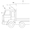
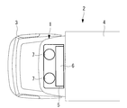
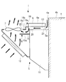
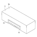
- FIG. 1st embodiment It is a top view of the vehicle carrying the transport refrigeration unit concerning a 1st embodiment. It is a side view of FIG. It is a typical side view of the transport refrigeration unit concerning a 1st embodiment. It is a typical perspective view of the control box concerning a 1st embodiment. It is the typical perspective view which showed the principal part of the refrigeration unit for transport which concerns on 1st Embodiment. It is a typical side view of the transport refrigeration unit concerning a 2nd embodiment.
- the vehicle 2 on which the transport refrigeration unit 1 according to the present embodiment is mounted is a transport truck in which a traveling engine (not shown) is disposed below the cab 3. .
- the cab 3 is rotatable by a predetermined angle around a shaft (not shown) extending in the vehicle width direction at the lower front end.
- the vehicle 2 has a van body 4 mounted on a frame extending in the front-rear direction behind the cab 3. In the van body 4, a load such as a frozen / refrigerated product is loaded.
- a transport refrigeration unit 1 is provided above the front surface 4a of the van body 4 so as to protrude above the cab 3 over substantially the entire region in the vehicle width direction.
- the transport refrigeration unit 1 supplies the generated cold air into the van body 4 so as to keep the inside of the van body 4 at a constant temperature.
- the transport refrigeration unit 1 includes a refrigeration device 5 fixed to the van body 4, a control box 6 installed on the upper surface 5 a of the refrigeration device 5, and an air guide path 20 described later. And a wind guide portion 8 forming a part.
- the transport refrigeration unit 1 has a substantially right triangle shape when viewed from the side, and the front surface 1a is inclined so that the length in the front-rear direction decreases from the top to the bottom. That is, the shape of the transport refrigeration unit 1 is such that the cab 3 and the transport refrigeration unit 1 do not interfere with each other when the cab 3 rotates as described above.
- a plurality of air holes (not shown) for introducing air into the transport refrigeration unit 1 are formed in the front face 1 a of the transport refrigeration unit 1.
- the refrigeration apparatus 5 is attached to the front surface 4 a of the van body 4, and includes an electric compressor (not shown), an evaporator (not shown), and two condenser fans 7 provided in front of the control box 6 so as to be arranged on the left and right.
- a refrigeration apparatus main body 11 that houses a generator (not shown) that generates electricity by the driving force of the traveling engine, and the front side 1a of the transport refrigeration unit 1 that is located in front of the refrigeration apparatus main body 11 And a condenser 12 arranged.
- the electric compressor, the evaporator, and the like disposed inside the refrigeration apparatus main body 11 and the condenser 12 are connected via a refrigerant pipe (not shown) to constitute a refrigeration cycle.
- Two condenser fans 7 are arranged above the condenser 12 and in front of the control box 6 so as to be aligned in the vehicle width direction (see FIGS. 2 and 3), and rotate around the vehicle vertical axis for transportation.
- the air inside the refrigeration unit 1 is discharged to the outside.
- the control box 6 has a substantially rectangular box shape extending in the vehicle width direction, and is arranged on the upper surface of the refrigeration apparatus main body 11 so that the rear surface of the control box 6 and the front surface 4a of the van body 4 are separated from each other.
- the front end of the control box 6 is located in front of the front end of the refrigeration apparatus 5.
- the upper surface 6 a of the control box 6 is lower than the upper surface 4 b of the van body 4.
- a control device (not shown) for controlling the refrigeration device 5 such as an inverter device or an AC / DC converter (for example, a three-phase full-wave rectifier using a diode) is housed inside the control box 6.
- the control box 6 is formed of an aluminum alloy or the like that is lightweight and has good heat conductivity. Further, as shown in FIGS. 4 and 5, a recess 13 is formed on the lower surface of the control box 6 at the substantially center in the vehicle width direction so as to extend in the front-rear direction and be recessed upward. Yes.
- heat radiation fins 14 for cooling heat-generating components such as an inverter device and an AC / DC converter housed in the control box 6 are provided integrally with the control box 6.
- the radiating fins 14 have a flat plate shape extending in the vehicle front-rear direction (that is, the direction in which the recess 13 extends), and are formed of an aluminum alloy or the like having good heat conductivity.
- the raw material of the control box 6 and the radiation fin 14 is not limited to an aluminum alloy.
- the control box may be formed of a steel plate made of iron.
- the radiating fins 14 are omitted.
- the air guide portion 8 includes a first air guide plate 15 extending forward from the upper front surface of the refrigeration apparatus 5 and a second air guide extending forward from the upper surface of the recess 13 of the control box 6. Plate 16.
- the first air guide plate 15 includes a flat plate-like lower surface portion 15a and side surface portions (not shown) that rise upward from both ends of the lower surface portion 15a in the vehicle width direction.
- the second air guide plate 16 includes a first horizontal portion 16a extending forward from the upper surface of the recess 13, a vertical portion 16b extending downward from the front end of the first horizontal portion 16a, and a second horizontal portion extending forward from the vertical portion 16b. 16c. Both ends in the vehicle width direction of the first horizontal portion 16a, the vertical portion 16b, and the second horizontal portion 16c are connected to the upper end of the side surface portion. That is, the first air guide plate 15 and the second air guide plate 16 form a duct-like closed space inside.
- the air guide portion 8 is curved or inclined at both ends in the vehicle width direction so that the width in the vehicle width direction increases toward the front.
- the left front end and the right front end of the air guide portion 8 are positioned in the vicinity of the condenser fans 7 provided on the left and right, respectively, and openings are formed at the left front end and the right front end of the air guide portion 8. That is, the air guide portion 8 is opened so as to face the entire vehicle width direction of the condenser fans 7 arranged on the left and right.
- the recess 13 is formed so that the lower surface of the control box 6 installed on the upper surface 5a of the refrigeration apparatus 5 is recessed upward, and extends in the front-rear direction over the entire region of the control box 6 in the front-rear direction. It is formed as follows. Further, the control box 6 is arranged away from the van body 4 located behind the control box 6. From this, the recessed part 13 becomes a duct structure extended in the front-back direction which has an opening in a front-end part and a rear-end part.
- the above-described air guide portion 8 extends in the form of a duct from the front end portion of the recess 13 to the vicinity of the condenser fan 7. Therefore, the recessed part 13 and the air guide part 8 are connected, and the air guide path 20 with the recessed part 13 as an upstream part and the air guide part 8 as a downstream part is formed.
- the air guide path 20 uses the rear end portion of the recess 13 as an inlet 21 for introducing outside air into the air guide path 20, and discharges air introduced through openings formed at the left front end and the right front end of the air guide section 8.
- a discharge port 22 is provided.
- the end portion on the discharge port 22 side of the first air guide plate 15 extends vertically below the blade portion of the condenser fan 7.
- the outside air near the upper surface of the transport refrigeration unit 1 is guided to the space between the van body 4 and the control box 6 and flows into the air guide path 20 from the air inlet 21 at the rear end portion of the control box 6.
- the gas is discharged from the discharge port 22.
- the outside air discharged from the discharge port 22 is directly guided upward (see FIGS. 3 and 5), and is discharged from the condenser fan 7 to the outside of the transport refrigeration unit 1.
- the control device can be cooled by heat exchange between the radiation fins 14 and the outside air. Further, since the outside air having a relatively low temperature is passed through the heat radiating fins 14, it is possible to cool the control device with the small heat radiating fins 14 compared with the case where the exhaust air of the condenser 12 is passed through the heat radiating fins 14. it can.
- the condenser fan 7 can vent the outside air that cools the control device to the radiation fins 14, Even when the vehicle is in a running state (for example, when the vehicle is stopped), the outside air can be passed through the heat dissipating fins 14 to cool the control device. Further, since the condenser fan 7 is used to vent the outside air to the heat radiating fins 14 for cooling the control device, it is not necessary to newly provide another fan or the like, and the number of parts can be reduced.
- the upper surface 6a of the control box 6 is lower than the upper surface 4b of the van body 4 (see FIG. 3).
- a part of the wind for example, traveling wind traveling from the front of the vehicle to the rear of the vehicle passes above the control box 6 and hits the front upper portion of the van body 4.
- the pressure increases in the vicinity thereof. Since the intake port 21 is opened between the control box 6 and the van body 4, the pressure difference between the intake port 21 and the discharge port 22 increases, and a large amount of outside air can be guided to the air guide path 20. Therefore, more outside air can be ventilated to the heat dissipating fins 14, and heat can be exchanged between the many outside air and the heat dissipating fins 14, so that the control device can be more suitably cooled.
- a recess 13 is formed in the control box 6, and a heat radiation fin 14 is disposed in the recess 13 (see FIG. 4). Therefore, the height of the control box 6 can be made without depending on the height of the radiating fins 14. Therefore, the height of the control box 6 can be suppressed, and consequently the height of the transport refrigeration unit 1 can also be suppressed. Further, since the height of the control box 6 disposed above the refrigeration apparatus 5 can be reduced, the refrigeration apparatus 5 can be disposed relatively above the van body 4.
- the van body 4 is provided with an outlet (not shown) through which the cold air generated by the refrigeration apparatus 5 is blown out. However, since the refrigeration apparatus 5 can be disposed relatively upper, The mouth can also be arranged in the relatively upper part of the van body 4.
- the recessed part 13 is formed in the lower surface of the control box 6 so that a control apparatus may be followed, and the recessed part 13 is dented upwards.
- the recess 13 of the control box 6 can be made a part of the air guide path 20. Therefore, it is not necessary to newly provide a part such as a duct dedicated to the air guide path, and the air guide path 20 can be formed while reducing the number of parts.
- the first air guide plate 15 and the second air guide plate 16 that form the air guide path 20 extend to the vicinity of the condenser fan 7. Therefore, outside air can be more reliably taken into the air guide path 20 to guide the outside air to the heat radiating fins 14, and the control device can be cooled.
- the first air guide plate 15 extends vertically below the condenser fan 7, but the first air guide plate 15 may not extend vertically below the condenser fan 7.
- the first air guide plate or the second air guide plate 16 only needs to extend to the vicinity of the condenser fan 7. The vicinity is preferably within 50 mm from the blade tip of the blade portion of the condenser fan 7 in plan view.
- the front end of the control box 6 is located in front of the front end of the refrigeration apparatus 5, but the positional relationship between the control box 6 and the refrigeration apparatus 5 is not limited to this.
- the front end of the control box 6 and the front end of the refrigeration apparatus 5 may be aligned, and the front end of the control box 6 may be located behind the front end of the refrigeration apparatus 5.
- the first horizontal portion 16a of the second air guide plate 16 extends forward from the upper surface of the recess 13 formed in the control box 6, the configuration described in the present embodiment (the front end of the control box 6). 1), the first horizontal portion 16a extends to form the air guide path 20 than the front end of the refrigeration apparatus 5).
- FIG. 6 a condenser fan 7 is disposed above the refrigeration apparatus 5, and a control box 6 is disposed in front of the condenser fan 7.
- the air guide portion 8 includes a first air guide plate 15 extending rearward from the lower surface of the control box 6 and a second air extending substantially parallel to the first air guide plate 15 rearward from the upper surface of the recess 13.
- a wind guide plate 16 Both ends of the first air guide plate 15 in the vehicle width direction rise upward and are connected to the second air guide plate 16 at the upper end.
- the air guide path 20 is located in front of the condenser fan 7, and the air inlet 21 is opened forward. Therefore, by using the dynamic pressure of the wind from the front of the vehicle toward the rear of the vehicle (for example, vehicle traveling wind), the outside air can be easily introduced into the intake port 21, and a large amount of outside air is introduced into the air duct and is passed through the heat radiation fins 14. can do. Therefore, heat can be exchanged between many outside air and the radiation fins 14, and the control box 6 can be suitably cooled. Further, when the vehicle travels, high-temperature exhaust air is discharged from the traveling engine, and the exhaust air flows from the exhaust port toward the rear of the vehicle by the vehicle travel air.
- the air guide path 20 is located at the front portion of the vehicle 2 and the intake port 21 is opened forward, the exhaust air of the traveling engine is hardly mixed into the outside air sucked from the intake port 21. Therefore, when the vehicle is traveling, the outside air flowing through the air guide path 20 can be kept at a low temperature, and the control box 6 can be suitably cooled.
- the present invention is not limited to the inventions according to the first embodiment and the second embodiment, and can be appropriately modified without departing from the scope of the invention.
- two condenser fans 7 are provided, but the number of condenser fans 7 may be one or three or more.
Landscapes
- Engineering & Computer Science (AREA)
- Physics & Mathematics (AREA)
- Thermal Sciences (AREA)
- Mechanical Engineering (AREA)
- General Engineering & Computer Science (AREA)
- Chemical & Material Sciences (AREA)
- Combustion & Propulsion (AREA)
- Microelectronics & Electronic Packaging (AREA)
- Devices That Are Associated With Refrigeration Equipment (AREA)
- Cooling Or The Like Of Electrical Apparatus (AREA)
- Cooling Or The Like Of Semiconductors Or Solid State Devices (AREA)
Abstract
制御ボックスに収納される制御装置を冷却する放熱フィンを小型化することができる輸送用冷凍ユニットを提供することを目的とする。凝縮器(12)及び凝縮器用ファン(7)を有する冷凍装置(5)と、冷凍装置(5)を制御する制御装置と、制御装置を冷却する放熱フィンを有する制御ボックス(6)と、放熱フィンに外気を導く導風路(8)とを備えた輸送用冷凍ユニット(1)において、凝縮器用ファン(7)が、凝縮器(12)を通過した空気及び導風路(8)内に配置された放熱フィンを通過した外気を排出する。
Description
本発明は、車両に搭載される輸送用冷凍ユニットに関するものである。
車両に搭載される輸送用冷凍ユニットには、走行用エンジンの駆動力によって発電機が発電した電力や、商用電源からの電力によって、圧縮機等を駆動させるものがある。このような輸送用冷凍ユニットは、発電機や圧縮機といった冷凍装置を制御する制御装置(例えば、インバータやAC/DC変換装置)を収納する制御ボックスが備えられることがあり、その際、制御ボックスには、発熱部品である制御装置(インバータやAC/DC変換装置等)を冷却するための放熱用のフィンが一体的に設けられることがある。
このような輸送用冷凍ユニットには、例えば特許文献1のようなものがある。特許文献1には、凝縮器用ファンの排風を電装品収納箱に一体的に形成された放熱フィンに導風して電装品収納箱に収納されたインバータやAC/DC変換装置を冷却する輸送用冷凍ユニットが開示されている。
しかしながら、特許文献1に記載の輸送用冷凍ユニットは、高温の凝縮器用ファンの排風と放熱フィンとで熱交換を行っているので、所要の放熱性能(冷却性能)を確保するためには、熱交換面積を大きくする必要があり、大型の放熱フィンを使用せざるを得なかった。特に、車両停車時においては、走行風による冷却効果を期待できないので、凝縮器用ファンの排風のみによって電装品収納箱を冷却しなければならず、このような場合を想定して、放熱フィンの設計は、凝縮器用ファンの排風のみで所要の放熱性能(冷却性能)を確保することができる大きさにする必要があった。
また、特許文献1に記載の輸送用冷凍ユニットでは、導風路の形状によっては、凝縮器用ファンの排風が淀んで凝縮器周辺に溜まり込んでしまい、凝縮器周辺の温度が上昇することで凝縮器の排風がより高温となり放熱フィンによる電装品収納箱の冷却性能が低下する可能性があった。
本発明は、このような事情に鑑みてなされたものであって、制御ボックスに収納される制御装置を冷却する放熱フィンを小型化することができる輸送用冷凍ユニットを提供することを目的とする。
上記課題を解決するために、本発明の輸送用冷凍ユニットは以下の手段を採用する。
すなわち、本発明の一態様に係る輸送用冷凍ユニットは、バンボディの前面に取り付けられ、凝縮器及び該凝縮器を通過した空気を排出する凝縮器用ファンを有する冷凍装置と、前記冷凍装置を制御する制御装置と、外面に前記制御装置を冷却する放熱フィンを有して該制御装置を収納する制御ボックスと、前記放熱フィンに外気を導くとともに、前記凝縮器用ファンの吸込側に該放熱フィンを通過した外気を導く導風路と、を備えている。
すなわち、本発明の一態様に係る輸送用冷凍ユニットは、バンボディの前面に取り付けられ、凝縮器及び該凝縮器を通過した空気を排出する凝縮器用ファンを有する冷凍装置と、前記冷凍装置を制御する制御装置と、外面に前記制御装置を冷却する放熱フィンを有して該制御装置を収納する制御ボックスと、前記放熱フィンに外気を導くとともに、前記凝縮器用ファンの吸込側に該放熱フィンを通過した外気を導く導風路と、を備えている。
上記構成では、導風路によって制御装置を冷却する放熱フィンに外気を通風しているので、放熱フィンと外気との熱交換によって制御装置を冷却することができる。
また、比較的低温である外気を放熱フィンに通風しているので、凝縮器の排風を放熱フィンに通風する場合に比べて、小型の放熱フィンで制御装置を冷却することができる。
また、導風路によって放熱フィンを通過した外気を凝縮器用ファンに導くこととしたので、凝縮器用ファンによって制御装置を冷却する外気を放熱フィンに通風することができ、何れの車両走行状態(例えば、車両停止状態)であっても放熱フィンに外気を通風し、制御装置を冷却することができる。
また、制御装置を冷却する放熱フィンに外気を通風するのに、凝縮器用ファンを利用しているので、新たに他のファン等を設ける必要がなく、部品点数を減らすことができる。
また、比較的低温である外気を放熱フィンに通風しているので、凝縮器の排風を放熱フィンに通風する場合に比べて、小型の放熱フィンで制御装置を冷却することができる。
また、導風路によって放熱フィンを通過した外気を凝縮器用ファンに導くこととしたので、凝縮器用ファンによって制御装置を冷却する外気を放熱フィンに通風することができ、何れの車両走行状態(例えば、車両停止状態)であっても放熱フィンに外気を通風し、制御装置を冷却することができる。
また、制御装置を冷却する放熱フィンに外気を通風するのに、凝縮器用ファンを利用しているので、新たに他のファン等を設ける必要がなく、部品点数を減らすことができる。
また、本発明の一態様に係る輸送用冷凍ユニットは、前記導風路は、外気を導入する吸気口を有し、前記凝縮器用ファンよりも後方に位置し、前記冷凍装置は、前記バンボディの前面に取り付けられ、前記制御ボックスは、前記冷凍装置の上面に前記バンボディの前面から離間するように配置され、前記吸気口は、前記制御ボックスと前記バンボディの前面との間に開口していてもよい。
車両走行時には、走行用エンジンから高温の排風が排出される。排出された排風は、車両走行風によって車両後方へ流れ、バンボディの前面を沿うように排風が上昇してくるが、上記構成ではバンボディの前面に冷凍装置を取り付け、冷凍装置の上方に導風路の吸気口を設けているので、上昇してくる排風を冷凍装置が遮断して、排風が吸気口まで至らない。したがって、吸気口から吸込む外気に走行用エンジンの排風が混入し難いので、車両走行時に、導風路に流通させる外気を低温に保つことができ、好適に制御ボックスを冷却することができる。
また、本発明の一態様に係る輸送用冷凍ユニットは、前記制御ボックスの上面は、前記バンボディの上面よりも低くなっていてもよい。
上記構成では、制御ボックスの上面がバンボディの上面よりも低くなっている。これにより、車両前方から車両後方へ向かう風(例えば走行風)の一部は、制御ボックスの上方を通過して、バンボディの前面上部に当たる。バンボディの前面上部に風が当たると、その近傍で圧力が高くなる。制御ボックスとバンボディとの間に吸気口が開口しているので、吸気口と排出口との圧力差が大きくなり、多くの外気を導風路に導くことができる。したがって、より多くの外気を放熱フィンに通風することができ、多くの外気と放熱フィンとが熱交換することができるので、制御装置をより好適に冷却することができる。
また、本発明の一態様に係る輸送用冷凍ユニットは、前記導風路は、外気を吸込む吸気口を有し、前記凝縮器用ファンよりも前方に位置し、前記吸気口は、前方に開口していてもよい。
上記構成では、導風路が凝縮器用ファンより前方に位置し、吸気口が前方に開口している。したがって、車両前方から車両後方へ向かう風(例えば車両走行風)の動圧を利用することで外気が吸気口に導入され易くなり、多くの外気を導風路に導入し放熱フィンに通風することができる。よって、多くの外気と放熱フィンとが熱交換することができ、制御ボックスを好適に冷却することができる。
また、車両走行時には、走行用エンジンから高温の排風が排出され、車両走行風によってその排風が排気口から車両後方へ向かって流れる。上記構成では、導風路が車両の前部に位置し、さらに吸気口が前方に開口しているので、吸気口から吸込む外気に走行用エンジンの排風が混入し難い。したがって、車両走行時に、導風路に流通させる外気を低温に保つことができ、好適に制御ボックスを冷却することができる。
また、車両走行時には、走行用エンジンから高温の排風が排出され、車両走行風によってその排風が排気口から車両後方へ向かって流れる。上記構成では、導風路が車両の前部に位置し、さらに吸気口が前方に開口しているので、吸気口から吸込む外気に走行用エンジンの排風が混入し難い。したがって、車両走行時に、導風路に流通させる外気を低温に保つことができ、好適に制御ボックスを冷却することができる。
また、本発明の一態様に係る輸送用冷凍ユニットは、前記制御ボックスの下面には、前記制御装置に沿うように上方に凹む凹部が形成され、前記放熱フィンは、前記凹部に配置され、前記凹部は、前記導風路の一部を構成していてもよい。
上記構成では、制御ボックスに凹部が形成され、その凹部に放熱フィンが配置されている。したがって、放熱フィンの高さに応じることのない制御ボックスの高さにすることができる。よって、制御ボックスの高さを抑制することができ、ひいては、輸送用冷凍ユニットの高さも抑制することができる。
また、上記構成では、制御ボックスの下面に制御装置に沿うように凹部を形成し、凹部は上方に凹んでいる。これにより、放熱フィンに外気を通風させる場合、制御ボックスの凹部を導風路の一部とすることができる。したがって、導風路専用のダクト等の部品を新たに設ける必要がなく、部品点数を減らしつつ、導風路を形成することができる。
また、上記構成では、制御ボックスの下面に制御装置に沿うように凹部を形成し、凹部は上方に凹んでいる。これにより、放熱フィンに外気を通風させる場合、制御ボックスの凹部を導風路の一部とすることができる。したがって、導風路専用のダクト等の部品を新たに設ける必要がなく、部品点数を減らしつつ、導風路を形成することができる。
また、本発明の一態様に係る輸送用冷凍ユニットは、前記凝縮器用ファンは、複数設けられ、前記導風路は、複数の前記凝縮器用ファンそれぞれに連通していてもよい。
上記構成では、複数の凝縮器用ファンに導風路が連結している。したがって、1つの凝縮器用ファンが故障した場合であっても、他の凝縮器用ファンによって、吸気口から外気を導風路に導いて制御装置を冷却することができる。
また、本発明の一態様に係る輸送用冷凍ユニットは、前記導風路は、導風板によって形成され、前記導風板は、前記凝縮器用ファン近傍まで延びていてもよい。
上記構成では、導風路を形成する導風板が凝縮器用ファン近傍まで延びている。したがって、より確実に導風路に外気を取り入れて放熱フィンに外気を導くことができ、制御装置を冷却することができる。
本発明によれば、制御ボックスに収納される制御装置を冷却する放熱フィンを小型化することができる。
以下に、本発明に係る実施形態について、図面を参照して説明する。
[第1実施形態]
以下、本発明の第1実施形態について、図1から図5を用いて説明する。
図1及び図2に示すように、本実施形態に係る輸送用冷凍ユニット1が搭載される車両2は、キャブ3の下方に走行用エンジン(図示省略)が配置される輸送用のトラックである。キャブ3は、前端下部で車幅方向に延びている軸(図示省略)を中心に所定角度だけ回転移動可能となっている。車両2は、キャブ3の後方で前後方向に延びるフレーム上にバンボディ4を搭載している。バンボディ4内には、冷凍・冷蔵品等の積み荷が積載される。
[第1実施形態]
以下、本発明の第1実施形態について、図1から図5を用いて説明する。
図1及び図2に示すように、本実施形態に係る輸送用冷凍ユニット1が搭載される車両2は、キャブ3の下方に走行用エンジン(図示省略)が配置される輸送用のトラックである。キャブ3は、前端下部で車幅方向に延びている軸(図示省略)を中心に所定角度だけ回転移動可能となっている。車両2は、キャブ3の後方で前後方向に延びるフレーム上にバンボディ4を搭載している。バンボディ4内には、冷凍・冷蔵品等の積み荷が積載される。
図1および図2に示すように、バンボディ4の前面4aの上方部には、車幅方向の略全域に亘って、キャブ3の上方に突出するように、輸送用冷凍ユニット1が設けられる。輸送用冷凍ユニット1は、生成した冷気をバンボディ4内に供給し、バンボディ4内を一定の温度に保つようになっている。
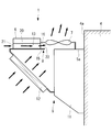
輸送用冷凍ユニット1は、図1及び図3に示すように、バンボディ4に固定される冷凍装置5と、冷凍装置5の上面5aに設置される制御ボックス6と、後述する導風路20の一部を形成する導風部8とを備える。輸送用冷凍ユニット1は、側面視略直角三角形状であって、上方から下方に向けて前後方向の長さが短くなるように、前面1aが傾斜している。すなわち、輸送用冷凍ユニット1の形状は、上述のキャブ3の回転移動の際に、キャブ3と輸送用冷凍ユニット1とが干渉しないような形状とされている。輸送用冷凍ユニット1の前面1aには、輸送用冷凍ユニット1内部に空気を導入する空気孔(図示省略)が複数形成されている。
冷凍装置5は、バンボディ4の前面4aに取り付けられ、電動圧縮機(図示省略)、蒸発器(図示省略)、制御ボックス6の前方に左右に並ぶように設けられる2台の凝縮器用ファン7と、走行用エンジンの駆動力により発電する発電機(図示省略)等が収容される冷凍装置本体部11と、冷凍装置本体部11の前方に位置し輸送用冷凍ユニット1の前面1aに沿うように配置される凝縮器12とを有する。冷凍装置本体部11の内部に配置された電動圧縮機及び蒸発器等と、凝縮器12とは冷媒配管(図示省略)を介して接続され、冷凍サイクルを構成している。
凝縮器用ファン7は、凝縮器12の上方かつ制御ボックス6の前方に車幅方向に並ぶように2台配置され(図2及び図3参照)、車両上下方向軸を中心に回転し、輸送用冷凍ユニット1の内部の空気を外部に排出する。
制御ボックス6は、車幅方向に延びる略矩形箱型であって、冷凍装置本体部11の上面に、制御ボックス6の後面とバンボディ4の前面4aとが離間するように配置される。制御ボックス6の前端は、冷凍装置5の前端よりも前方に位置する。制御ボックス6の上面6aは、バンボディ4の上面4bよりも低くなっている。制御ボックス6の内部には、インバータ装置やAC/DC変換装置(例えば、ダイオードを使った三相全波整流器)といった冷凍装置5を制御する制御装置(図示省略)が収納されている。
制御ボックス6は、軽量で伝熱性の良いアルミ合金等で形成されている。また、図4及び図5に示されているように、制御ボックス6の車幅方向略中央の下面には、前後方向の全域に亘って、前後に延びて上方に凹む凹部13が形成されている。凹部13には、制御ボックス6内に収納されたインバータ装置やAC/DC変換装置といった発熱部品を冷却するための放熱フィン14が制御ボックス6と一体的に設けられている。放熱フィン14は、車両前後方向(すなわち、凹部13の延びる方向)に沿って延びる平板状であって、伝熱性の良いアルミ合金等で形成される。なお、制御ボックス6及び放熱フィン14の原料はアルミ合金に限定されない。例えば、鉄を原料とした鋼板で制御ボックスを形成してもよい。なお、図5では放熱フィン14(図4参照)を省略して図示している。
図3に示されているように、導風部8は、冷凍装置5の上部前面から前方に延びる第1導風板15と、制御ボックス6の凹部13の上面から前方に延びる第2導風板16とを有する。第1導風板15は、平板状の下面部15aと、下面部15aの車幅方向の両端から上方に立ち上がる側面部(図示省略)とを有する。
第2導風板16は、凹部13の上面から前方に延びる第1水平部16aと、第1水平部16aの前端から下方に延びる鉛直部16bと、鉛直部16bから前方に延びる第2水平部16cとを有する。第1水平部16a、鉛直部16b及び第2水平部16cの車幅方向両端は、側面部の上端と連結される。すなわち、第1導風板15と第2導風板16とで内部にダクト状の閉空間を形成している。
また、導風部8は、図5に破線で一部を示すように、前方にむかうにつれ車幅方向の幅が大きくなるように、車幅方向の両端部が湾曲ないし傾斜している。導風部8の左前端及び右前端はそれぞれ、左右に設けられた凝縮器用ファン7近傍に位置し、導風部8の左前端及び右前端には開口が形成されている。すなわち、導風部8は、左右に並べられた凝縮器用ファン7の車幅方向全体に面するように開口している。
また、導風部8は、図5に破線で一部を示すように、前方にむかうにつれ車幅方向の幅が大きくなるように、車幅方向の両端部が湾曲ないし傾斜している。導風部8の左前端及び右前端はそれぞれ、左右に設けられた凝縮器用ファン7近傍に位置し、導風部8の左前端及び右前端には開口が形成されている。すなわち、導風部8は、左右に並べられた凝縮器用ファン7の車幅方向全体に面するように開口している。
制御ボックス6の凹部13及び導風部8で形成される導風路20について説明する。上記したように、凹部13は、冷凍装置5の上面5aに設置される制御ボックス6の下面を上方に凹ませるように形成され、制御ボックス6の前後方向の全領域に亘って前後方向に延びるように形成されている。また、制御ボックス6は、制御ボックス6の後方に位置するバンボディ4とは離間して配置されている。このことから、凹部13は前端部分及び後端部分に開口を有する前後に延びるダクト構造となる。
凹部13の前端部分から、上述した導風部8がダクト状に凝縮器用ファン7の近傍まで延びている。したがって、凹部13及び導風部8は連結され、凹部13を上流部分、導風部8を下流部分とした導風路20が形成される。導風路20は、凹部13の後端部分を導風路20内に外気を導入する吸気口21とし、導風部8の左前端及び右前端に形成された開口を導入した空気を排出する排出口22としている。第1導風板15の排出口22側端部は、凝縮器用ファン7の翼部の鉛直下方まで延びている。
次に、輸送用冷凍ユニット1内を通過する空気の流れについて説明する。図3及び図5に実線矢印及び破線矢印で示すように、凝縮器用ファン7が駆動すると、輸送用冷凍ユニット1の前面近傍の外気は、輸送用冷凍ユニット1の前面に形成された空気孔及び凝縮器12を通過した後に、上方に導かれ、凝縮器用ファン7から輸送用冷凍ユニット1の外部に排出される。また、凝縮器用ファン7が駆動すると、排出口22近傍の空気が凝縮器用ファン7側に吸い込まれることで、導風路20内に流れが形成される。これにより、輸送用冷凍ユニット1の上面近傍の外気は、バンボディ4と制御ボックス6との間の空間に導かれ、制御ボックス6の後端部分の吸気口21から導風路20内に流入し、排出口22から排出される。排出口22から排出された外気は、そのまま上方に導かれ(図3及び図5参照)、凝縮器用ファン7から輸送用冷凍ユニット1の外部に排出される。
本実施形態によれば、以下の作用を奏する。
導風路20によって制御ボックス6内の制御装置を冷却する放熱フィン14に外気を通風しているので、放熱フィン14と外気との熱交換によって制御装置を冷却することができる。
また、比較的低温である外気を放熱フィン14に通風しているので、凝縮器12の排風を放熱フィン14に通風する場合に比べて、小型の放熱フィン14で制御装置を冷却することができる。
また、導風路20によって放熱フィン14を通過した外気を凝縮器用ファン7に導くこととしたので、凝縮器用ファン7によって、制御装置を冷却する外気を放熱フィン14に通風することができ、何れの車両走行状態(例えば、車両停止状態)であっても放熱フィン14に外気を通風し、制御装置を冷却することができる。
また、制御装置を冷却する放熱フィン14に外気を通風するのに、凝縮器用ファン7を利用しているので、新たに他のファン等を設ける必要がなく、部品点数を減らすことができる。
導風路20によって制御ボックス6内の制御装置を冷却する放熱フィン14に外気を通風しているので、放熱フィン14と外気との熱交換によって制御装置を冷却することができる。
また、比較的低温である外気を放熱フィン14に通風しているので、凝縮器12の排風を放熱フィン14に通風する場合に比べて、小型の放熱フィン14で制御装置を冷却することができる。
また、導風路20によって放熱フィン14を通過した外気を凝縮器用ファン7に導くこととしたので、凝縮器用ファン7によって、制御装置を冷却する外気を放熱フィン14に通風することができ、何れの車両走行状態(例えば、車両停止状態)であっても放熱フィン14に外気を通風し、制御装置を冷却することができる。
また、制御装置を冷却する放熱フィン14に外気を通風するのに、凝縮器用ファン7を利用しているので、新たに他のファン等を設ける必要がなく、部品点数を減らすことができる。
車両走行時には、キャブ3の下方に配置された走行用エンジンから高温の排風が排出される。排出された排風は、車両走行風によってキャブ3の後方へ流れ、バンボディ4の前面4aに沿うように上昇する。しかし、上記構成ではバンボディ4の前面4aに冷凍装置5を取り付け、冷凍装置5の上面5aに導風路20を設けているので(図3参照)、上昇してくる排風を冷凍装置5が遮断して、排風が導風路20まで至らない。したがって、吸気口21から吸込む外気に走行用エンジンの排風が混入し難いので、車両走行時に、導風路20に流通させる外気を低温に保つことができ、好適に制御ボックス6内の制御装置を冷却することができる。
制御ボックス6の上面6aがバンボディ4の上面4bよりも低くなっている(図3参照)。これにより、車両前方から車両後方へ向かう風(例えば走行風)の一部は、制御ボックス6の上方を通過して、バンボディ4の前面上部に当たる。バンボディ4の前面上部に風が当たると、その近傍で圧力が高くなる。制御ボックス6とバンボディ4との間に吸気口21が開口しているので、吸気口21と排出口22との圧力差が大きくなり、多くの外気を導風路20に導くことができる。したがって、より多くの外気を放熱フィン14に通風することができ、多くの外気と放熱フィン14とが熱交換することができるので、制御装置をより好適に冷却することができる。
制御ボックス6に凹部13が形成され、その凹部13に放熱フィン14が配置されている(図4参照)。したがって、放熱フィン14の高さに応じることのない制御ボックス6の高さにすることができる。よって、制御ボックス6の高さを抑制することができ、ひいては、輸送用冷凍ユニット1の高さも抑制することができる。
また、冷凍装置5の上方に配置される制御ボックス6の高さを低くすることができるので、冷凍装置5をバンボディ4の比較的上部に配置することができる。バンボディ4の内部には、冷凍装置5で生成された冷気を内部に吹出す吹出し口(図示省略)が設けられているが、冷凍装置5を比較的上部に配置することができるので、この吹出し口もバンボディ4内の比較的上部に配置することができる。したがって、バンボディ4内に荷物を積載する場合に、吹出し口と荷物とを干渉し難くすることができる。
また、制御ボックス6の下面に制御装置に沿うように凹部13を形成し、凹部13は上方に凹んでいる。これにより、放熱フィン14に外気を通風させる場合、制御ボックス6の凹部13を導風路20の一部とすることができる。したがって、導風路専用のダクト等の部品を新たに設ける必要がなく、部品点数を減らしつつ、導風路20を形成することができる。
また、冷凍装置5の上方に配置される制御ボックス6の高さを低くすることができるので、冷凍装置5をバンボディ4の比較的上部に配置することができる。バンボディ4の内部には、冷凍装置5で生成された冷気を内部に吹出す吹出し口(図示省略)が設けられているが、冷凍装置5を比較的上部に配置することができるので、この吹出し口もバンボディ4内の比較的上部に配置することができる。したがって、バンボディ4内に荷物を積載する場合に、吹出し口と荷物とを干渉し難くすることができる。
また、制御ボックス6の下面に制御装置に沿うように凹部13を形成し、凹部13は上方に凹んでいる。これにより、放熱フィン14に外気を通風させる場合、制御ボックス6の凹部13を導風路20の一部とすることができる。したがって、導風路専用のダクト等の部品を新たに設ける必要がなく、部品点数を減らしつつ、導風路20を形成することができる。
凝縮器用ファン7が2つ設けられ、それぞれの凝縮器用ファン7近傍まで導風路20が延びている(図5参照)。したがって、片方の凝縮器用ファン7が故障した場合であっても、もう一方の凝縮器用ファン7によって、吸気口21から外気を導風路20に導いて制御装置を冷却することができる。
導風路20を形成する第1導風板15及び第2導風板16が凝縮器用ファン7近傍まで延びている。したがって、より確実に導風路20に外気を取り入れて放熱フィン14に外気を導くことができ、制御装置を冷却することができる。
なお、本実施形態では、第1導風板15が凝縮器用ファン7の鉛直下方まで延びているが、第1導風板15が凝縮器用ファン7の鉛直下方まで延びていなくてもよい。第1導風板または第2導風板16が凝縮器用ファン7の近傍まで延びていればよい。近傍とは、平面視で凝縮器用ファン7の翼部の翼端から50mm以内が好適である。
また、本実施形態では、制御ボックス6の前端は、冷凍装置5の前端よりも前方に位置しているが、制御ボックス6と冷凍装置5との位置関係はこれに限定されない。制御ボックス6の前端と冷凍装置5の前端とが揃っていてもよく、制御ボックス6の前端が冷凍装置5の前端よりも後方に位置してもよい。なお、この場合でも第2導風板16の第1水平部16aは制御ボックス6に形成された凹部13の上面から前方に延びているので、本実施形態で説明した構成(制御ボックス6の前端が冷凍装置5の前端よりも前方に位置する構成)よりも、第1水平部16aが延長して導風路20を形成することになる。
[第2実施形態]
次に、本発明の第2実施形態について、図6を用いて説明する。
本実施形態は、上記した第1実施形態に対して、制御ボックス6、凝縮器用ファン7及び導風部8の配置等が異なっている。第1実施形態と同様の点については説明を省略する。
本実施形態に係る輸送用冷凍ユニット1は、図6に示すように、冷凍装置5の上方に凝縮器用ファン7を配置し、凝縮器用ファン7の前方に制御ボックス6を配置している。また、本実施形態に係る導風部8は、制御ボックス6の下面から後方に延びる第1導風板15と、凹部13の上面から後方に第1導風板15と略平行に延びる第2導風板16とを備える。第1導風板15の車幅方向両端部は、上方に立ち上がり、上端部で第2導風板16と連結する。
次に、本発明の第2実施形態について、図6を用いて説明する。
本実施形態は、上記した第1実施形態に対して、制御ボックス6、凝縮器用ファン7及び導風部8の配置等が異なっている。第1実施形態と同様の点については説明を省略する。
本実施形態に係る輸送用冷凍ユニット1は、図6に示すように、冷凍装置5の上方に凝縮器用ファン7を配置し、凝縮器用ファン7の前方に制御ボックス6を配置している。また、本実施形態に係る導風部8は、制御ボックス6の下面から後方に延びる第1導風板15と、凹部13の上面から後方に第1導風板15と略平行に延びる第2導風板16とを備える。第1導風板15の車幅方向両端部は、上方に立ち上がり、上端部で第2導風板16と連結する。
本実施形態に係る輸送用冷凍ユニット1内を通過する空気の流れについて説明する。図6に矢印で示すように、凝縮器用ファン7が駆動すると、輸送用冷凍ユニット1の前面近傍の外気は、輸送用冷凍ユニット1の前面に形成された空気孔及び凝縮器12を通過した後に、後ろ斜め上方に導かれ、凝縮器用ファン7から輸送用冷凍ユニット1の外部に排出される。また、凝縮器用ファン7が駆動すると、制御ボックス6の前面近傍の外気は、制御ボックスの前面の吸気口21から導風路20内に流入し、排出口22から排出される。排出口22から排出された外気は、そのまま上方に導かれ、凝縮器用ファン7から輸送用冷凍ユニット1の外部に排出される。
本実施形態によれば、以下の作用を奏する。
導風路20が凝縮器用ファン7より前方に位置し、吸気口21が前方に開口している。したがって、車両前方から車両後方へ向かう風(例えば車両走行風)の動圧を利用することで外気が吸気口21に導入され易くなり、多くの外気を導風路に導入し放熱フィン14に通風することができる。よって、多くの外気と放熱フィン14とが熱交換することができ、制御ボックス6を好適に冷却することができる。
また、車両走行時には、走行用エンジンから高温の排風が排出され、車両走行風によってその排風が排気口から車両後方へ向かって流れる。上記構成では、導風路20が車両2の前部に位置し、さらに吸気口21が前方に開口しているので、吸気口21から吸込む外気に走行用エンジンの排風が混入し難い。したがって、車両走行時に、導風路20に流通させる外気を低温に保つことができ、好適に制御ボックス6を冷却することができる。
導風路20が凝縮器用ファン7より前方に位置し、吸気口21が前方に開口している。したがって、車両前方から車両後方へ向かう風(例えば車両走行風)の動圧を利用することで外気が吸気口21に導入され易くなり、多くの外気を導風路に導入し放熱フィン14に通風することができる。よって、多くの外気と放熱フィン14とが熱交換することができ、制御ボックス6を好適に冷却することができる。
また、車両走行時には、走行用エンジンから高温の排風が排出され、車両走行風によってその排風が排気口から車両後方へ向かって流れる。上記構成では、導風路20が車両2の前部に位置し、さらに吸気口21が前方に開口しているので、吸気口21から吸込む外気に走行用エンジンの排風が混入し難い。したがって、車両走行時に、導風路20に流通させる外気を低温に保つことができ、好適に制御ボックス6を冷却することができる。
なお、本発明は、上記第1実施形態及び第2実施形態に係る発明に限定されるものではなく、その要旨を逸脱しない範囲において、適宜変形が可能である。例えば、上記第1実施形態及び第2実施形態では、凝縮器用ファン7を2台設けているが、凝縮器用ファン7の数は単数であってもよいし、3台以上であってもよい。
1 輸送用冷凍ユニット
4 バンボディ
5 冷凍装置
6 制御ボックス
7 凝縮器用ファン
8 導風部
12 凝縮器
13 凹部
14 放熱フィン
15 第1導風板
16 第2導風板
20 導風路
21 吸気口
22 排出口
4 バンボディ
5 冷凍装置
6 制御ボックス
7 凝縮器用ファン
8 導風部
12 凝縮器
13 凹部
14 放熱フィン
15 第1導風板
16 第2導風板
20 導風路
21 吸気口
22 排出口
Claims (7)
- バンボディの前面に取り付けられ、凝縮器及び該凝縮器を通過した空気を排出する凝縮器用ファンを有する冷凍装置と、
前記冷凍装置を制御する制御装置と、
外面に前記制御装置を冷却する放熱フィンを有し、該制御装置を収納する制御ボックスと、
前記放熱フィンに外気を導くとともに、前記凝縮器用ファンの吸込側に該放熱フィンを通過した外気を導く導風路と、
を備えている輸送用冷凍ユニット。 - 前記導風路は、外気を導入する吸気口を有し、前記凝縮器用ファンよりも後方に位置し、
前記冷凍装置は、前記バンボディの前面に取り付けられ、
前記制御ボックスは、前記冷凍装置の上面に前記バンボディの前面から離間するように配置され、
前記吸気口は、前記制御ボックスと前記バンボディの前面との間に開口する請求項1に記載の輸送用冷凍ユニット。 - 前記制御ボックスの上面は、前記バンボディの上面よりも低くなっている請求項2に記載の輸送用冷凍ユニット。
- 前記導風路は、外気を吸込む吸気口を有し、前記凝縮器用ファンよりも前方に位置し、
前記吸気口は、前方に開口している請求項1に記載の輸送用冷凍ユニット。 - 前記制御ボックスの下面には、前記制御装置に沿うように上方に凹む凹部が形成され、
前記放熱フィンは、前記凹部に配置され、
前記凹部は、前記導風路の一部を構成する請求項1から請求項4のいずれかに記載の輸送用冷凍ユニット。 - 前記凝縮器用ファンは、複数設けられ、
前記導風路は、複数の前記凝縮器用ファンそれぞれに連通している請求項1から請求項5のいずれかに記載の輸送用冷凍ユニット。 - 前記導風路は、導風板によって形成され、
前記導風板は、前記凝縮器用ファン近傍まで延びている請求項1から請求項6のいずれかに記載の輸送用冷凍ユニット。
Priority Applications (1)
| Application Number | Priority Date | Filing Date | Title |
|---|---|---|---|
| EP17815282.3A EP3415844B1 (en) | 2016-06-20 | 2017-06-15 | Refrigerating unit for transportation |
Applications Claiming Priority (2)
| Application Number | Priority Date | Filing Date | Title |
|---|---|---|---|
| JP2016-122102 | 2016-06-20 | ||
| JP2016122102A JP6186578B1 (ja) | 2016-06-20 | 2016-06-20 | 輸送用冷凍ユニット |
Publications (1)
| Publication Number | Publication Date |
|---|---|
| WO2017221814A1 true WO2017221814A1 (ja) | 2017-12-28 |
Family
ID=59720288
Family Applications (1)
| Application Number | Title | Priority Date | Filing Date |
|---|---|---|---|
| PCT/JP2017/022224 Ceased WO2017221814A1 (ja) | 2016-06-20 | 2017-06-15 | 輸送用冷凍ユニット |
Country Status (3)
| Country | Link |
|---|---|
| EP (1) | EP3415844B1 (ja) |
| JP (1) | JP6186578B1 (ja) |
| WO (1) | WO2017221814A1 (ja) |
Families Citing this family (7)
| Publication number | Priority date | Publication date | Assignee | Title |
|---|---|---|---|---|
| JP6942584B2 (ja) * | 2017-09-25 | 2021-09-29 | 三菱重工サーマルシステムズ株式会社 | 輸送用冷凍ユニット |
| KR102563739B1 (ko) * | 2018-06-20 | 2023-08-17 | 한온시스템 주식회사 | 차량용 전장품 냉각 장치 |
| CN110303292A (zh) * | 2019-04-17 | 2019-10-08 | 东莞市德铫实业有限公司 | 一种铝散热片制作成型工艺 |
| JP7048905B2 (ja) * | 2020-03-06 | 2022-04-06 | ダイキン工業株式会社 | 輸送用冷凍装置および輸送用コンテナ |
| EP4394288B1 (en) | 2021-10-28 | 2026-04-29 | Mitsubishi Heavy Industries Thermal Systems, Ltd. | Transport refrigeration unit |
| US20240093930A1 (en) * | 2022-09-16 | 2024-03-21 | Carrier Corporation | Cooling system for a variable frequency drive in a transport refrigeration unit |
| JP2025158843A (ja) * | 2024-04-05 | 2025-10-17 | 三菱重工サーマルシステムズ株式会社 | 高電圧回路ユニット及び輸送用冷凍機械 |
Citations (5)
| Publication number | Priority date | Publication date | Assignee | Title |
|---|---|---|---|---|
| JP2003097881A (ja) * | 2001-09-20 | 2003-04-03 | Mitsubishi Heavy Ind Ltd | コンテナ用冷凍装置 |
| JP2008128540A (ja) * | 2006-11-20 | 2008-06-05 | Denso Corp | 冷凍車用冷凍機ユニット |
| JP2011007480A (ja) * | 2009-05-25 | 2011-01-13 | Daikin Industries Ltd | トレーラ用冷凍装置 |
| JP2015127630A (ja) * | 2013-09-30 | 2015-07-09 | ダイキン工業株式会社 | コンテナ用冷凍装置 |
| JP5754917B2 (ja) * | 2010-11-05 | 2015-07-29 | 三菱重工業株式会社 | 車両輸送用冷凍ユニット |
Family Cites Families (5)
| Publication number | Priority date | Publication date | Assignee | Title |
|---|---|---|---|---|
| JPH062993U (ja) * | 1992-06-12 | 1994-01-14 | 日新電機株式会社 | インバータ素子冷却装置 |
| JPH08163877A (ja) * | 1994-12-05 | 1996-06-21 | Nippondenso Co Ltd | 電力変換装置およびその製造方法 |
| JPH10294579A (ja) * | 1997-04-18 | 1998-11-04 | Sansha Electric Mfg Co Ltd | 電源装置 |
| JP2011257087A (ja) * | 2010-06-10 | 2011-12-22 | Denso Corp | 冷凍庫用冷凍装置 |
| JP5940372B2 (ja) * | 2012-05-21 | 2016-06-29 | シャープ株式会社 | 照明装置 |
-
2016
- 2016-06-20 JP JP2016122102A patent/JP6186578B1/ja active Active
-
2017
- 2017-06-15 EP EP17815282.3A patent/EP3415844B1/en active Active
- 2017-06-15 WO PCT/JP2017/022224 patent/WO2017221814A1/ja not_active Ceased
Patent Citations (5)
| Publication number | Priority date | Publication date | Assignee | Title |
|---|---|---|---|---|
| JP2003097881A (ja) * | 2001-09-20 | 2003-04-03 | Mitsubishi Heavy Ind Ltd | コンテナ用冷凍装置 |
| JP2008128540A (ja) * | 2006-11-20 | 2008-06-05 | Denso Corp | 冷凍車用冷凍機ユニット |
| JP2011007480A (ja) * | 2009-05-25 | 2011-01-13 | Daikin Industries Ltd | トレーラ用冷凍装置 |
| JP5754917B2 (ja) * | 2010-11-05 | 2015-07-29 | 三菱重工業株式会社 | 車両輸送用冷凍ユニット |
| JP2015127630A (ja) * | 2013-09-30 | 2015-07-09 | ダイキン工業株式会社 | コンテナ用冷凍装置 |
Also Published As
| Publication number | Publication date |
|---|---|
| JP6186578B1 (ja) | 2017-08-30 |
| EP3415844A1 (en) | 2018-12-19 |
| JP2017227352A (ja) | 2017-12-28 |
| EP3415844A4 (en) | 2019-05-01 |
| EP3415844B1 (en) | 2020-08-05 |
Similar Documents
| Publication | Publication Date | Title |
|---|---|---|
| JP6186578B1 (ja) | 輸送用冷凍ユニット | |
| EP2710868B1 (en) | Variable frequency drive heat sink assembly | |
| US10403868B2 (en) | Battery | |
| US20100182750A1 (en) | Industrial vehicle with electric component unit | |
| CN103842198A (zh) | 车辆前部结构 | |
| CN102482984A (zh) | 空气引入结构 | |
| US7730734B2 (en) | Cooling apparatus of a fuel cell vehicle | |
| JP5024353B2 (ja) | 電気機器の冷却システム | |
| US8763735B2 (en) | Cooling system for electric vehicle and cooling method for electrical component | |
| JP2010274675A (ja) | 燃料電池システム | |
| CN103543804A (zh) | 散热装置 | |
| JP2005178427A (ja) | 自動車のブレーキ冷却構造 | |
| JP5440826B2 (ja) | 外気導入グリル | |
| JP5754917B2 (ja) | 車両輸送用冷凍ユニット | |
| JP6166743B2 (ja) | 電力変換装置 | |
| JP2014058935A (ja) | 車両用ヒートポンプ装置 | |
| JP2016119286A (ja) | 電池パック | |
| JP2018017445A (ja) | 輸送用冷凍ユニット | |
| CN107953740B (zh) | 空调单元 | |
| CN114619980B (zh) | 车辆下部罩构造 | |
| CN108140469B (zh) | 车辆用变压器 | |
| JP2016047692A (ja) | 電力変換装置およびそれを搭載した鉄道車両 | |
| CN1923558A (zh) | 铁道车辆用液冷式电力变换装置 | |
| JP2016078654A (ja) | 電力変換装置およびそれを搭載した鉄道車両 | |
| CN115447342B (zh) | 车辆空调散热系统及车辆 |
Legal Events
| Date | Code | Title | Description |
|---|---|---|---|
| WWE | Wipo information: entry into national phase |
Ref document number: 2017815282 Country of ref document: EP |
|
| ENP | Entry into the national phase |
Ref document number: 2017815282 Country of ref document: EP Effective date: 20180914 |
|
| 121 | Ep: the epo has been informed by wipo that ep was designated in this application |
Ref document number: 17815282 Country of ref document: EP Kind code of ref document: A1 |
|
| NENP | Non-entry into the national phase |
Ref country code: DE |